EP3935343B1 - Noncontact sensor calibration using single axis movement - Google Patents
Noncontact sensor calibration using single axis movement Download PDFInfo
- Publication number
- EP3935343B1 EP3935343B1 EP20716629.9A EP20716629A EP3935343B1 EP 3935343 B1 EP3935343 B1 EP 3935343B1 EP 20716629 A EP20716629 A EP 20716629A EP 3935343 B1 EP3935343 B1 EP 3935343B1
- Authority
- EP
- European Patent Office
- Prior art keywords
- calibration
- machine
- artifact
- axis
- view
- Prior art date
- Legal status (The legal status is an assumption and is not a legal conclusion. Google has not performed a legal analysis and makes no representation as to the accuracy of the status listed.)
- Active
Links
Images










Classifications
-
- G—PHYSICS
- G01—MEASURING; TESTING
- G01B—MEASURING LENGTH, THICKNESS OR SIMILAR LINEAR DIMENSIONS; MEASURING ANGLES; MEASURING AREAS; MEASURING IRREGULARITIES OF SURFACES OR CONTOURS
- G01B11/00—Measuring arrangements characterised by the use of optical techniques
- G01B11/002—Measuring arrangements characterised by the use of optical techniques for measuring two or more coordinates
- G01B11/005—Measuring arrangements characterised by the use of optical techniques for measuring two or more coordinates coordinate measuring machines
-
- G—PHYSICS
- G01—MEASURING; TESTING
- G01B—MEASURING LENGTH, THICKNESS OR SIMILAR LINEAR DIMENSIONS; MEASURING ANGLES; MEASURING AREAS; MEASURING IRREGULARITIES OF SURFACES OR CONTOURS
- G01B11/00—Measuring arrangements characterised by the use of optical techniques
- G01B11/24—Measuring arrangements characterised by the use of optical techniques for measuring contours or curvatures
- G01B11/2416—Measuring arrangements characterised by the use of optical techniques for measuring contours or curvatures of gears
-
- G—PHYSICS
- G01—MEASURING; TESTING
- G01B—MEASURING LENGTH, THICKNESS OR SIMILAR LINEAR DIMENSIONS; MEASURING ANGLES; MEASURING AREAS; MEASURING IRREGULARITIES OF SURFACES OR CONTOURS
- G01B21/00—Measuring arrangements or details thereof, where the measuring technique is not covered by the other groups of this subclass, unspecified or not relevant
- G01B21/02—Measuring arrangements or details thereof, where the measuring technique is not covered by the other groups of this subclass, unspecified or not relevant for measuring length, width, or thickness
- G01B21/04—Measuring arrangements or details thereof, where the measuring technique is not covered by the other groups of this subclass, unspecified or not relevant for measuring length, width, or thickness by measuring coordinates of points
- G01B21/042—Calibration or calibration artifacts
Definitions
- the present invention relates to the calibration of non-contact sensors for inspecting workpieces including gears and other toothed articles, particularly on functional measurement platforms that produce analytical test results.
- the invention uses single axis movement for calibration.
- CMM Coordinat Measurement Machine
- GMM Global Measurement Machines
- a typical CMM or GMM utilizes at least one contact probe.
- a non-contact sensor e.g. laser
- Both probing technologies (i.e. contact and non-contact) on these machines utilize a calibration method which usually involves use of a single sphere.
- Analytical testing of gears may be done by either a GMM or CMM.
- These machines include a computer controlled apparatus which includes a high resolution touch sensor (e.g. tactile probe) and/or a non-contact probe.
- the machine of WO 2018/048872 is an example of an analytical machine for inspecting a gear workpiece utilizing a touch sensor and/or a laser sensor for inspection. Both sensors require calibration before inspecting gears.
- CMM and GMM machines are both equipped with probes capable of measuring the location of points on the surface of workpieces. This is one of the core functions of these machines and is used to implement the full range of functionality available on these machines (e.g. measuring size, location, deviation from theoretical surface and form of geometric shapes). These measurements are checked against certain tolerances to ensure the correct fit and function of the measured workpieces.
- the machine To measure a workpiece, the machine must convert the signal output from its probe (or probes) and the respective position of the relevant machine axes into the location of points on the surface of a workpiece.
- This is often implemented as a mathematical function or model which utilized a probe signal as an output and machine data as an input.
- the model is ultimately used to output the location of points on the surface of a workpiece.
- This model uses parameters which account for assembly and manufacturing variability in the probe and machine (e.g. probe orientation, offset, and scale factors). These parameters are often referred to as probe calibration parameters (or coefficients). Determining these parameters accurately is critical to the operation of the machine. The process of determining these parameters is known as the probe calibration.
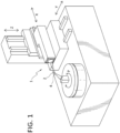
- CMM and GMM machines equipped with a tactile probe typically use a single sphere (known as the calibration sphere) as a reference for determining the probe calibration parameters. See the machine 1 of Figure 1 for example.
- the machine axes (X, Y, Z, P) move to touch the probe tip 2 to the calibration sphere 4 in multiple locations with several probe deflections.
- the probe tip calibration parameters are computed to a high degree of accuracy using the data (probe deflection signal, axis positions) collected during this process.
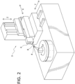
- CMM and GMM machines equipped with a non-contact two-dimensional (2D) profile sensor (e.g. laser) 6 utilize a method similar to tactile probe calibration. See the machine 3 of Figure 2 for example.
- Such a machine typically uses a single sphere 4 (known as the calibration sphere) as a reference for determining probe location, orientation, and scale.
- These parameters are referred to as the probe calibration parameters and the parameters are critical to converting the data output by the probe (a list of depth measurements across the field of view of the sensor) into accurate three-dimensional (3D) point-cloud data which is needed to perform measurements.
- the process of determining these parameters is known as probe calibration.
- the machine axes (X, Y, Z, P) move the probe so that its field of view 8 moves across the sphere.
- the machine performs several such moves, each slightly different such that the sphere 4 occupies a different region in the field of view 8 of the probe 6.
- Figure 3 shows the sphere 4 positioned in the upper-left portion of the field of view 8 with a small portion of the sphere 4 protruding above the field of view.
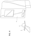
- Figure 4 shows repositioning of the field of view 8 in the Z direction such that a large portion of the sphere 4 protrudes above the field of view.
- Figure 5 shows the sphere 4 located in the upper-right portion of the field of view 8 with a small portion of the sphere 4 protruding above the field of view.
- Figure 5 Compared to Figure 4 , the position of Figure 5 was reached via movement in the Z and Y directions.
- Figure 6 shows the sphere 4 located in the lower-right portion of the field of view 8 with a small portion of the sphere 4 protruding above the field of view.
- the position of Figure 6 was reached via movement in the X direction.
- the probe calibration parameters are computed to a high degree of accuracy using the data (probe data, axis positions) collected during this process.
- the method discussed above includes utilization of at least one linear axis to calibrate a non-contact sensor.
- the machine In order to perform a calibration process the machine must be equipped with linear axes motions which permit such movement to be performed. Without the ability to re-position the probe via the machine axes, the sphere is restricted to a small portion of the probe's field of view. The data (probe data, axis positions) that may be collected with such a restriction is not sufficient to accurately determine the probe calibration parameters.
- FIGS 7 , 8 and 9 show a machine 50 comprising at least one non-contact sensor 52 on a functional testing platform for workpiece inspection and/or measurement.
- the machine per se, is of the type disclosed in WO 2019/083932 .
- the machine 50 comprises a production gear 16 (i.e. the workpiece) and master gear 14 mounted on respective workholding arbors 18 and 12, such as mechanical, hydraulic or pneumatic arbors as is known to the skilled artisan.
- the production gear 16 may be located on either the left hand side or on the right hand side of the master gear 14 but is shown on the left side in Figure 7 .
- the gear 16 rotates on a motorized axis W.
- the master gear 14 is mounted on right hand side (axis T) and is not motorized.
- the rotation of master gear 14 is provided by the driving motor for axis W and the engagement with the production gear 16.
- the master gear 14 is on a slide 26 (X axis) and is moveable in the direction of the X axis to allow coupling and decoupling of gears. Decoupling is required so that the production gear 16 can be removed and replaced with different workpieces either manually or via automation means.
- a linear scale 7 ( Figure 9 ) is mounted to capture movement of the slide 26 in the X axis direction during operation.
- a rotary encoder (not shown) is mounted below the motorized production gear 16 (axis W) to capture rotary movement of the workpiece gear. Inputs of the rotary encoder and the linear scale are captured so that during rotation of gear pair, relative movement of gears (in the X direction) is measured with respect to the rotary position of the workpiece gear 16.
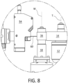
- a non-contact sensor such as a laser assembly 52 is positioned on left side of the machine for analytical testing.
- a single laser 54 is mounted on a linearly adjustable post 56 having an adjustable mounting mechanism 58 whereby the laser 54 is movable and positionable in up to three linear directions X, Y, Z (preferably mutually perpendicular) and in up to three rotational directions, that is, about each of X, Y and Z for manually setting the operating position of the laser.
- laser 54 is preferably capable of six degree-of freedom movement but only for set-up purposes.
- Such adjustability is preferable in order to orient the laser line 60 onto a gear tooth space whereby it can capture at least a portion of the tooth involute (i.e. profile direction) from root-to-tip for both tooth flanks of adjacent teeth.
- the only computer-controlled axis on the machine of Figure 7 for analytical testing is the workpiece rotational axis W.
- the machine lacks the ability to re-position the probe via the one or more linear axes.
- Computer controlled positioning of a workpiece 16 relative to laser 54 in mutually perpendicular directions X, Y and Z is not possible and, hence, calibration of laser 54 is not possible using the techniques discussed above.
- SCHICK "Metrology CT technology and its applications in the precision engineering industry", SPIE, PO BOX 10 BELLINGHAM WA 98227-0010, USA, vol. 7522, 7 May 2010 (2010-05-07), XP040534878 discloses the use of X-ray CT in metrology to reach also inner surfaces that are not accessible to a tactile or optical probe.
- FENG LI ET AL. "A practical coordinate unification method for integrated tactile-optical measuring system", OPTICS AND LASERS IN ENGINEERING, vol. 55, 1 April 2014 (2014-04-01), pages 189-196, XP055126944, ISSN: 0143-8166, DOI: 10.1016/j.optlaseng.2013.11.004 discloses a coordinate unification method for integrated tactile-optical measuring system.
- WEN-LONG LI ET AL. "A new calibration method between an optical sensor and a rotating platform in turbine blade inspection", MEASUREMENT SCIENCE AND TECHNOLOGY, IOP, BRISTOL, GB, vol. 28, no. 3, 2 February 2017 (2017-02-02), page 35009, XP020313833, ISSN: 0957-0233, DOI: 10.1088/1361-6501/AA50DF [retrieved on 2017-02-02 ] relates to turbine blade inspection and calibrates the transformation relationship between the translating movement of an optical sensor and the rotating movement to calculate rotation axis and rotation center of the rotating platform mounted on the same anti-vibration platform than the translating platform of the sensor.
- CN 107 741 198 A (BEIJING HUARUI SHENGDE TECH CO. LTD. ET AL.) 27 February 2018 (2018-02-27) discloses to add a rotary table to a traditional three-coordinate measuring machine utilizing two standard spheres and driving the standard sphere to move to 7 different positions.
- the invention provides a gear inspection machine with the features of claim 1. It comprises a calibration artifact and allows a probe calibration whereby calibration can be performed without the use of machine axes capable of three dimensional positioning of a probe relative to a calibration sphere.
- the invention comprises a calibration artifact for a machine having a laser sensor with an associated field of view.
- the calibration artifact is rotatable about an axis of rotation of the machine in a direction on the machine.
- the calibration artifact comprises a top side and a plurality of shaped calibration surfaces arranged on at least one surface on the top side of the calibration artifact.
- the calibration surfaces are arranged at different locations on at least one top side surface with respect to the field of view of said laser sensor.
- the inventive method includes a plurality of calibration spheres fixed in relation to one another via a rigid structure comprising a calibration artifact body.
- the spheres are mounted such that each will be sensed by the probe at some position of a machine axis. In other words, the spheres lie in the region swept out by the sensor field of view over the movement of the machine axis.
- the calibration spheres are located at known positions and the calibration artifact body is designed such that it may be mounted in a known location in place of a work piece.
- the invention comprises a machine axis capable of moving a probe and a calibration artifact relative to one another, the machine comprising a rotary axis.
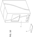
- Figure 10 is an enlarged view of a laser sensor 6 and its associated field of view 8 as noted in the embodiments discussed above.
- Figure 11 is a simplified view of an analytical testing arrangement as may be found on a machine such as the machine of Figure 7 .
- a gear workpiece 11 is rotatable about machine workpiece axis, W, with the teeth 12 of gear 10 passing through the field of view 8 of laser sensor 6 as the gear 10 is rotated in direction R as indicated by the arrow.
- the laser sensor 6 is slightly tilted so as to provide a vertical component to the field of view 8.
- the only machine motion available in Figure 11 is workpiece rotation about the W axis. Similar to Figure 7 , laser sensor 6 is set in a fixed position as is the workpiece spindle 20 of the machine.
- the present invention addresses the inability to adequately re-position a probe, particularly a non-contacting sensor such as a laser sensor, with respect to a calibration sphere, or other shaped calibration surfaces, as discussed above, preferably with respect to analytical gear testing machines having a limited number of controlled axes (e.g. one rotational axis).
- Figure 12 shows a calibration artifact 30 being circular is shape (e.g. generally disk-shaped), having a top side and a bottom side (not shown), and being rotatable about an axis (e.g. axis D).
- the calibration artifact 30 is capable of being positioned for rotation on a workpiece spindle of a machine such as an analytical gear testing machine.
- the artifact 30 comprises a central hub 32 which is positionable on a workpiece spindle of a machine via appropriate workholding equipment as is well understood by the skilled artisan.
- Artifact 30 further comprises a plurality of arms 34 (three shown in Figure 12 ) extending radially from hub 32 to an outer circumferential portion 36 at least a portion of which comprises a circumferential face portion 38 located on one side (i.e. top side in Figure 12 ) of the artifact adjacent to the periphery 44 of the artifact.
- Face portion 38 preferably comprises a plurality of distinct flat (e.g. ground) surfaces, preferably three flat surfaces 39, 41 and 43, each of which is located at a different axial position relative to one another in the direction of rotational axis D.
- other types of structures of the artifact 30 are possible (e.g. solid disk).
- the artifact 30 comprises a plurality of calibration spheres 40 (three shown) fixed in relation to one another via a rigid structure 42, such as pins or posts, that are attached, preferably via a threaded connection, to the face portion 38, in particular to flat surfaces 39, 41 and 43, of the artifact 30.
- the spheres 40 are positioned with respect to one another such that when each sphere is located within the field of view 8 of a laser, each sphere will occupy a location within the field of view that is different than the respective locations of the other spheres of the artifact.
- three groups of threaded/tapped holes marked A, B and C are provided, one group of holes per flat surface 39, 41 and 43, where pins or posts 42 connect to the flat surfaces 39, 41, 43 of the artifact 30.
- All locations A are positioned at the same radial distance from the axis D.
- all locations B are positioned at the same radial distance from the axis D and all locations C are positioned at the same radial distance from the axis D.
- the respective radial distances for A, B and C are different from one another.
- the radial positions of spheres in each group of A, B and C will not be the same.
- each sphere 40 of the artifact 30 will be in different axial position and, hence, will protrude above, or below, the field of view 8 by different amounts as the sphere passes through the field of view.
- three positions A, B and C are preferred, the invention is not limited thereto as more than three are contemplated.
- the artifact 30 comprises three groups of holes A, B, C spaced about the top surface of the artifact, preferably equidistantly at 120 degree intervals, with preferably one group of holes in each of the "stepped" flat surfaces 39, 41 and 43.
- the radial locations of holes A, B, C preferably coincide with certain locations on a gear corresponding in size.
- the radial distance to "B" times 2 (r B x 2) preferably coincides with the pitch diameter (i.e. at the pitch line) of the corresponding gear.
- the radial distance to "A" times 2 (r A x 2) preferably represents a diameter greater than the pitch diameter of the corresponding gear
- the radial distance to "C" times 2 (r C x 2) preferably represents a diameter less than the pitch diameter of the corresponding gear.
- the actual diameter of the artifact is not relevant to the calibration process but the diameter must be such that the artifact does not interfere with the laser 6 or any other machine component.
- a single size of sphere 40 and pin/post 42 may be utilized.
- commercially available probe tips comprising a threaded post and sphere are utilized on the artifact.
- the face portion 38 of the artifact may lie in a single plane and posts of different lengths provided so as to enable spheres of different axial positions.
- the spheres 40 are mounted such that each sphere will be sensed by the probe (e.g. laser) as the artifact rotates about the axis, such as the axis of workpiece rotation of the testing machine, and each sphere passes through the field of view 8. See Figure 13 .
- the spheres 40 lie in the region swept out by the sensor field of view 8 over the movement of the machine workpiece rotational axis W (which is coincident with axis D when the calibration artifact 30 is positioned on the machine spindle).
- the calibration spheres 40 are located at known positions either by precise construction or by inspection on a suitable coordinate measuring machine.
- the body of the calibration artifact is designed such that it may be mounted in a known location in place of a work piece.
- Figures 14-19 illustrate examples of utilizing the artifact 30 in the machine calibration process.
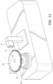
- Figure 14 shows a sphere 40 located at position A as the sphere enters the field of view 8 which is slightly tilted (see the tilted sensor 6 in Figure 13 ).
- the dashed line represents the plane of the tilted field of view 8.
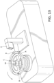
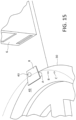
- Figure 15 shows a sphere 40 located at position A that, due to rotation of the artifact 30, is located near the edge of the field of view 8 and is about to leave the field of view as rotation of the artifact about axis W continues. Because of the tilted field of view, the cross-section of the sphere passing through the field of view decreases as the sphere moves from entry to exit in the field of view 8. Note the amount of sphere 40 protruding above the field view 8 in Figure 14 and Figure 15 .
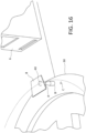
- Figure 16 shows a sphere 40 located at position B as the sphere enters the field of view 8 which is slightly tilted (see the tilted sensor 6 in Figure 13 ).
- the dashed line represents the plane of the tilted field of view 8.
- Figure 17 shows a sphere 40 located at position B that, due to rotation of the artifact 30, is located near the edge of the field of view 8 and is about to leave the field of view as rotation of the artifact about axis W continues. Because of the tilted field of view, the cross-section of the sphere passing through the field of view decreases as the sphere moves from entry to exit in the field of view 8. Note the amount of sphere 40 protruding above the field view 8 in Figure 16 and Figure 17 .
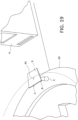
- Figure 18 shows a sphere 40 located at position C as the sphere enters the field of view 8 which is slightly tilted (see the tilted sensor 6 in Figure 13 ).
- the dashed line represents the plane of the tilted field of view 8.
- Figure 19 shows a sphere 40 located at position C that, due to rotation of the artifact 30, is located near the middle of the field of view 8 as rotation of the artifact about axis W continues. Because of the tilted field of view, the cross-section of the sphere passing through the field of view decreases as the sphere moves from entry toward exit in the field of view 8. Note the amount of sphere 40 protruding above the field view 8 in Figure 19 and Figure 19 .
- the calibration method steps comprise the following:
- the invention is used with a machine that is equipped with axes capable of three-dimensional (3D) positioning of a probe.
- the method is performed as described previously while the 3D positioning system is stationary (or without significant movement).
- the invention may be useful under any one of the following circumstances:
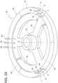
- Figure 20 shows a calibration artifact 30 including multiple calibration spheres 40 held at a similar radius (A, B, C) and axial positions (39, 41, 43) as discussed above.
- the eccentricity and/or tilt of the artifact 30 may be determined in addition to the calibration parameters previously described.
- eccentricity and/or tilt of the artifact 30 may be determined by comparing all position "A" spheres to one another and/or comparing all position "B" spheres to one another and/or comparing all position "C" spheres to one another.
- sphere 40 While a sphere 40 is shown at all radial positions A, B and C, the minimum number of spheres 40 for determining eccentricity and tilt would be for one sphere at each of the A, B, or C positions. Thus, in Figure 20 for example, spheres 40 at each "A" position would be sufficient for determining eccentricity and tilt.
- the eccentricity and tilt can be used to compensate the measurement of a similarly mounted workpiece.
- Figures 21-25 illustrate a not claimed example where a machine 68 includes an axis M which is used as a translational (e.g. linear) movement axis for a non-contact sensor 77 (e.g. laser) and its associated field of view 78.
- the calibration artifact 70 consists of multiple calibration spheres 72 held at a small offsets 74 from a line parallel to the movement axis M. Artifact 70 comprises two flat surfaces 71, 73 although additional offset surfaces may be included.
- the calibration spheres 72 may be grouped or arranged in the same pattern on surfaces 71 and 73 and may be closely spaced so that multiple spheres may be in the field of view 78 at the same time.
- artifact 70 may be flat with the calibration spheres 72 in one group positioned at a different height above the surface of the artifact 70 than the spheres of any other group.
- Figures 21-24 show examples of movement of the field of view 78 relative to the artifact 70 and spheres 72 (right to left in Figures 21-24 as normally viewed) in direction M.
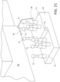
- Figure 21 shows the field of view 78 at its initial contact with a sphere 72 of the artifact 70.
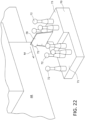
- Figure 22 shows the field of view 78 contacting the final sphere near the inner end of a first flat surface portion 73 of the artifact 70.
- Figure 23 shows the field of view 78 contacting a sphere near the middle of a subsequent flat surface portion 71 of the artifact 70.
- Figure 24 shows the field of view 78 contacting the final sphere near the outer end of the subsequent flat surface portion 71 of the artifact 70.
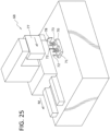
- Figure 25 shows a schematic view of a mechanism for moving a non-contact sensor 77 (e.g. laser) and its associated field of view 78 relative to an artifact 70 comprising multiple spheres 72 arranged on a plurality of flat surfaces located at different heights relative to the sensor 77 and the field of view 78.
- a non-contact sensor 77 e.g. laser
- an artifact 70 comprising multiple spheres 72 arranged on a plurality of flat surfaces located at different heights relative to the sensor 77 and the field of view 78.
- the calibration artifact 70 may comprise a plurality of spheres wherein each sphere is mounted and probed as described above in turn via a precision mounting system (such as a kinematic mount). Each sphere (or group thereof) is probed in turn after mounting. The data collected for each may then be used together to determine the calibration parameters. Using such a mounting system, a single calibration sphere may be used, probed multiple times, and then mounted in a different location.
- a precision mounting system such as a kinematic mount
- the invention additionally contemplates a calibration artifact as described above but using pins or cylinders, involute helicoid or other geometric shapes instead of or in addition to spheres.
- the invention may be performed simultaneously (in parallel) or successively with multiple sensors thereby enabling the calibration of each sensor accurately in relation to every other sensor. This allows the data collected by multiple probes to be combined and used together accurately (e.g. measuring the relationship between two features measured by separate probes).
Landscapes
- Physics & Mathematics (AREA)
- General Physics & Mathematics (AREA)
- Length Measuring Devices With Unspecified Measuring Means (AREA)
- Length Measuring Devices By Optical Means (AREA)
- A Measuring Device Byusing Mechanical Method (AREA)
Description
- The present invention relates to the calibration of non-contact sensors for inspecting workpieces including gears and other toothed articles, particularly on functional measurement platforms that produce analytical test results. The invention uses single axis movement for calibration.
- For many years analytical testing of gears has been done using a CMM (Coordinate Measurement Machine) or a GMM (Gear Measurement Machines). A typical CMM or GMM utilizes at least one contact probe. In recent years, a non-contact sensor (e.g. laser) has been used to inspect same gears as is disclosed in
WO 2018/048872 , the disclosure of which is hereby incorporated by reference. Both probing technologies (i.e. contact and non-contact) on these machines utilize a calibration method which usually involves use of a single sphere. - Analytical testing of gears may be done by either a GMM or CMM. These machines include a computer controlled apparatus which includes a high resolution touch sensor (e.g. tactile probe) and/or a non-contact probe. The machine of
WO 2018/048872 is an example of an analytical machine for inspecting a gear workpiece utilizing a touch sensor and/or a laser sensor for inspection. Both sensors require calibration before inspecting gears. - CMM and GMM machines are both equipped with probes capable of measuring the location of points on the surface of workpieces. This is one of the core functions of these machines and is used to implement the full range of functionality available on these machines (e.g. measuring size, location, deviation from theoretical surface and form of geometric shapes). These measurements are checked against certain tolerances to ensure the correct fit and function of the measured workpieces.
- To measure a workpiece, the machine must convert the signal output from its probe (or probes) and the respective position of the relevant machine axes into the location of points on the surface of a workpiece. This is often implemented as a mathematical function or model which utilized a probe signal as an output and machine data as an input. The model is ultimately used to output the location of points on the surface of a workpiece. This model uses parameters which account for assembly and manufacturing variability in the probe and machine (e.g. probe orientation, offset, and scale factors). These parameters are often referred to as probe calibration parameters (or coefficients). Determining these parameters accurately is critical to the operation of the machine. The process of determining these parameters is known as the probe calibration.
- CMM and GMM machines equipped with a tactile probe typically use a single sphere (known as the calibration sphere) as a reference for determining the probe calibration parameters. See the
machine 1 ofFigure 1 for example. During the probe calibration the machine axes (X, Y, Z, P) move to touch the probe tip 2 to thecalibration sphere 4 in multiple locations with several probe deflections. The probe tip calibration parameters are computed to a high degree of accuracy using the data (probe deflection signal, axis positions) collected during this process. - CMM and GMM machines equipped with a non-contact two-dimensional (2D) profile sensor (e.g. laser) 6 utilize a method similar to tactile probe calibration. See the
machine 3 ofFigure 2 for example. Such a machine typically uses a single sphere 4 (known as the calibration sphere) as a reference for determining probe location, orientation, and scale. These parameters (probe location, orientation, and scale coefficients) are referred to as the probe calibration parameters and the parameters are critical to converting the data output by the probe (a list of depth measurements across the field of view of the sensor) into accurate three-dimensional (3D) point-cloud data which is needed to perform measurements. The process of determining these parameters is known as probe calibration. - During the probe calibration process, the machine axes (X, Y, Z, P) move the probe so that its field of
view 8 moves across the sphere. The machine performs several such moves, each slightly different such that thesphere 4 occupies a different region in the field ofview 8 of theprobe 6. For example,Figure 3 shows thesphere 4 positioned in the upper-left portion of the field ofview 8 with a small portion of thesphere 4 protruding above the field of view.Figure 4 shows repositioning of the field ofview 8 in the Z direction such that a large portion of thesphere 4 protrudes above the field of view.Figure 5 shows thesphere 4 located in the upper-right portion of the field ofview 8 with a small portion of thesphere 4 protruding above the field of view. Compared toFigure 4 , the position ofFigure 5 was reached via movement in the Z and Y directions. Finally,Figure 6 shows thesphere 4 located in the lower-right portion of the field ofview 8 with a small portion of thesphere 4 protruding above the field of view. Compared toFigure 5 , the position ofFigure 6 was reached via movement in the X direction. The probe calibration parameters are computed to a high degree of accuracy using the data (probe data, axis positions) collected during this process. - The method discussed above includes utilization of at least one linear axis to calibrate a non-contact sensor. In order to perform a calibration process the machine must be equipped with linear axes motions which permit such movement to be performed. Without the ability to re-position the probe via the machine axes, the sphere is restricted to a small portion of the probe's field of view. The data (probe data, axis positions) that may be collected with such a restriction is not sufficient to accurately determine the probe calibration parameters.
-
Figures 7 ,8 and9 show amachine 50 comprising at least onenon-contact sensor 52 on a functional testing platform for workpiece inspection and/or measurement. The machine, per se, is of the type disclosed inWO 2019/083932 . Themachine 50 comprises a production gear 16 (i.e. the workpiece) andmaster gear 14 mounted onrespective workholding arbors production gear 16 may be located on either the left hand side or on the right hand side of themaster gear 14 but is shown on the left side inFigure 7 . Thegear 16 rotates on a motorized axis W. Themaster gear 14 is mounted on right hand side (axis T) and is not motorized. The rotation ofmaster gear 14 is provided by the driving motor for axis W and the engagement with theproduction gear 16. - For functional testing, the
master gear 14 is on a slide 26 (X axis) and is moveable in the direction of the X axis to allow coupling and decoupling of gears. Decoupling is required so that theproduction gear 16 can be removed and replaced with different workpieces either manually or via automation means. A linear scale 7 (Figure 9 ) is mounted to capture movement of theslide 26 in the X axis direction during operation. A rotary encoder (not shown) is mounted below the motorized production gear 16 (axis W) to capture rotary movement of the workpiece gear. Inputs of the rotary encoder and the linear scale are captured so that during rotation of gear pair, relative movement of gears (in the X direction) is measured with respect to the rotary position of theworkpiece gear 16. - As shown in
Figure 7 , a non-contact sensor such as alaser assembly 52 is positioned on left side of the machine for analytical testing. Asingle laser 54 is mounted on a linearlyadjustable post 56 having anadjustable mounting mechanism 58 whereby thelaser 54 is movable and positionable in up to three linear directions X, Y, Z (preferably mutually perpendicular) and in up to three rotational directions, that is, about each of X, Y and Z for manually setting the operating position of the laser. In other words,laser 54 is preferably capable of six degree-of freedom movement but only for set-up purposes. Such adjustability is preferable in order to orient thelaser line 60 onto a gear tooth space whereby it can capture at least a portion of the tooth involute (i.e. profile direction) from root-to-tip for both tooth flanks of adjacent teeth. - However, the only computer-controlled axis on the machine of
Figure 7 for analytical testing is the workpiece rotational axis W. The machine lacks the ability to re-position the probe via the one or more linear axes. Computer controlled positioning of aworkpiece 16 relative tolaser 54 in mutually perpendicular directions X, Y and Z (i.e. three dimensional) is not possible and, hence, calibration oflaser 54 is not possible using the techniques discussed above. - G. SCHICK: "Metrology CT technology and its applications in the precision engineering industry", SPIE, PO discloses the use of X-ray CT in metrology to reach also inner surfaces that are not accessible to a tactile or optical probe.
-
DE 197 33 711 A1 (LEITZ BROWN & SHARPE MESTECHNI [DE]) 11 February 1999 (1999-02-11 ) discloses a method to check the geometrical deviations of the Z-axis of a coordinate measurement device. - MORONI GIOVANNI ET AL.: "Four-axis micro measuring systems performance verification", CIRP ANNALS, ELSEVIER BV, NL, CH, FR, vol. 63, no. 1, 4 April 2014 (2014-04-04), pages 485-488, XP029033583, ISSN: 0007-8506, DOI: 10.1016/J.CIRP.2014.03.033 discloses a coordinate unification method for integrated tactile-optical measuring systems.
- FENG LI ET AL.: "A practical coordinate unification method for integrated tactile-optical measuring system", OPTICS AND LASERS IN ENGINEERING, vol. 55, 1 April 2014 (2014-04-01), pages 189-196, XP055126944, ISSN: 0143-8166, DOI: 10.1016/j.optlaseng.2013.11.004 discloses a coordinate unification method for integrated tactile-optical measuring system.
- WEN-LONG LI ET AL.: "A new calibration method between an optical sensor and a rotating platform in turbine blade inspection", MEASUREMENT SCIENCE AND TECHNOLOGY, IOP, BRISTOL, GB, vol. 28, no. 3, 2 February 2017 (2017-02-02), page 35009, XP020313833, ISSN: 0957-0233, DOI: 10.1088/1361-6501/AA50DF [retrieved on 2017-02-02] relates to turbine blade inspection and calibrates the transformation relationship between the translating movement of an optical sensor and the rotating movement to calculate rotation axis and rotation center of the rotating platform mounted on the same anti-vibration platform than the translating platform of the sensor.
-
CN 107 741 198 A (BEIJING HUARUI SHENGDE TECH CO. LTD. ET AL.) 27 February 2018 (2018-02-27) discloses to add a rotary table to a traditional three-coordinate measuring machine utilizing two standard spheres and driving the standard sphere to move to 7 different positions. - The invention provides a gear inspection machine with the features of
claim 1. It comprises a calibration artifact and allows a probe calibration whereby calibration can be performed without the use of machine axes capable of three dimensional positioning of a probe relative to a calibration sphere. - The invention comprises a calibration artifact for a machine having a laser sensor with an associated field of view. The calibration artifact is rotatable about an axis of rotation of the machine in a direction on the machine. The calibration artifact comprises a top side and a plurality of shaped calibration surfaces arranged on at least one surface on the top side of the calibration artifact. The calibration surfaces are arranged at different locations on at least one top side surface with respect to the field of view of said laser sensor.
- The inventive method includes a plurality of calibration spheres fixed in relation to one another via a rigid structure comprising a calibration artifact body. The spheres are mounted such that each will be sensed by the probe at some position of a machine axis. In other words, the spheres lie in the region swept out by the sensor field of view over the movement of the machine axis. The calibration spheres are located at known positions and the calibration artifact body is designed such that it may be mounted in a known location in place of a work piece.
-
-
Figure 1 is a schematic representation of a multi-axis CMM and GMM equipped with a tactile probe and a single sphere (known as the calibration sphere) as a reference for determining the probe calibration parameters. -
Figure 2 is a schematic representation of a multi-axis CMM and GMM equipped with a non-contact probe and a single sphere (known as the calibration sphere) as a reference for determining the probe calibration parameters. -
Figure 3 shows a calibration sphere occupying a region in the field of view of the probe during calibration of the non-contact probe of the machine ofFigure 2 . -
Figure 4 shows a calibration sphere occupying another region in the field of view of the probe during calibration of the non-contact probe of the machine ofFigure 2 . -
Figure 5 shows a calibration sphere occupying yet another region in the field of view of the probe during calibration of the non-contact probe of the machine ofFigure 2 . -
Figure 6 shows a calibration sphere occupying still another region in the field of view of the probe during calibration of the non-contact probe of the machine ofFigure 2 . -
Figure 7 illustrates a machine comprising at least one non-contact sensor on a functional testing platform for workpiece, particularly gears, inspection and/or measurement. -
Figure 8 shows an enlarged view of the non-contact sensor on the machine ofFigure 7 . -
Figure 9 shows a top view of the machine ofFigure 7 . -
Figure 10 is an enlarged view of a laser sensor and its associated field of view. -
Figure 11 illustrates a simplified view of an analytical gear testing machine. -
Figure 12 shows a calibration artifact in accordance with the invention. -
Figure 13 shows the calibration artifact ofFigure 12 operable on an analytical gear testing machine of the type shown inFigure 11 . -
Figure 14 shows a sphere located at defined position on a calibration artifact as the sphere enters a field of view of a non-contact probe during calibration of the probe. -
Figure 15 shows the sphere ofFigure 14 as the sphere is near to leaving the field of view of the non-contact probe during calibration of the probe. -
Figure 16 shows a sphere located at another defined position on a calibration artifact as the sphere enters a field of view of a non-contact probe during calibration of the probe. -
Figure 17 shows the sphere ofFigure 16 as the sphere is near to leaving the field of view of the non-contact probe during calibration of the probe. -
Figure 18 shows a sphere located at yet another defined position on a calibration artifact as the sphere enters a field of view of a non-contact probe during calibration of the probe. -
Figure 19 shows the sphere ofFigure 18 as the sphere is near the middle of the field of view of the non-contact probe during calibration of the probe. -
Figure 20 illustrates a calibration sphere including multiple calibration spheres held at a similar radius and axial positions. -
Figure 21 2 . illustrates a not-claimed example of a calibration artifact and sensor arrangement for translational movement and comprising multiple calibration spheres held at a small offsets. The field of view is shown at its initial contact with a sphere of the artifact. -
Figure 22 shows the example ofFigure 21 with the field of view contacting the final sphere near the inner end of a first flat surface portion of the artifact. -
Figure 23 shows the embodiment ofFigure 21 with the field of view contacting a sphere near the middle of a subsequent flat surface portion of the artifact. -
Figure 24 shows the example ofFigure 21 with the field of view contacting the final sphere near the outer end of the subsequent flat surface portion of the artifact. -
Figure 25 shows a schematic view of a mechanism for moving a non-contact sensor and its associated field of view relative to the artifact ofFigure 21 . - The terms "invention," "the invention," and "the present invention" used in this specification are intended to refer broadly to all of the subject matter of any patent claims below. Statements containing these terms should not be understood to limit the subject matter described herein or to limit the meaning or scope of any patent claims below. Furthermore, this specification does not seek to describe or limit the subject matter covered by any claims in any particular part, paragraph, statement or drawing of the application. The subject matter should be understood by reference to the entire specification, all drawings and any claim below. The invention is capable of other constructions and of being practiced or being carried out in various ways. Also, it is understood that the phraseology and terminology used herein is for the purposes of description and should not be regarded as limiting.
- The details of the invention will now be discussed with reference to the accompanying drawings which illustrate the invention by way of example only. In the drawings, similar features or components will be referred to by like reference numbers. For a better understanding of the invention and ease of viewing, doors and any internal or external guarding have been omitted from the drawings.
- The use of "including", "having" and "comprising" and variations thereof herein is meant to encompass the items listed thereafter and equivalents thereof as well as additional items. The words "a" and "an" are understood to mean "one or more" unless a clear intent to limit to only one is specifically recited. The use of letters to identify elements of a method or process is simply for identification and is not meant to indicate that the elements should be performed in a particular order.
- Although references may be made below to directions such as upper, lower, upward, downward, rearward, bottom, top, front, rear, etc., in describing the drawings, these references are made relative to the drawings (as normally viewed) for convenience. These directions are not intended to be taken literally or limit the present invention in any form. In addition, terms such as "first", "second", "third", etc., are used to herein for purposes of description and are not intended to indicate or imply importance or significance unless specifically recited.
- The invention comprises a machine axis capable of moving a probe and a calibration artifact relative to one another, the machine comprising a rotary axis.
-
Figure 10 is an enlarged view of alaser sensor 6 and its associated field ofview 8 as noted in the embodiments discussed above.Figure 11 is a simplified view of an analytical testing arrangement as may be found on a machine such as the machine ofFigure 7 . In the simplified view of an analytical gear testing machine ofFigure 11 , a gear workpiece 11 is rotatable about machine workpiece axis, W, with theteeth 12 ofgear 10 passing through the field ofview 8 oflaser sensor 6 as thegear 10 is rotated in direction R as indicated by the arrow. Thelaser sensor 6 is slightly tilted so as to provide a vertical component to the field ofview 8. The only machine motion available inFigure 11 is workpiece rotation about the W axis. Similar toFigure 7 ,laser sensor 6 is set in a fixed position as is theworkpiece spindle 20 of the machine. - The present invention addresses the inability to adequately re-position a probe, particularly a non-contacting sensor such as a laser sensor, with respect to a calibration sphere, or other shaped calibration surfaces, as discussed above, preferably with respect to analytical gear testing machines having a limited number of controlled axes (e.g. one rotational axis).
-
Figure 12 shows acalibration artifact 30 being circular is shape (e.g. generally disk-shaped), having a top side and a bottom side (not shown), and being rotatable about an axis (e.g. axis D). Thecalibration artifact 30 is capable of being positioned for rotation on a workpiece spindle of a machine such as an analytical gear testing machine. InFigure 12 , theartifact 30 comprises acentral hub 32 which is positionable on a workpiece spindle of a machine via appropriate workholding equipment as is well understood by the skilled artisan.Artifact 30 further comprises a plurality of arms 34 (three shown inFigure 12 ) extending radially fromhub 32 to an outercircumferential portion 36 at least a portion of which comprises acircumferential face portion 38 located on one side (i.e. top side inFigure 12 ) of the artifact adjacent to theperiphery 44 of the artifact.Face portion 38 preferably comprises a plurality of distinct flat (e.g. ground) surfaces, preferably threeflat surfaces artifact 30 are possible (e.g. solid disk). - The
artifact 30 comprises a plurality of calibration spheres 40 (three shown) fixed in relation to one another via arigid structure 42, such as pins or posts, that are attached, preferably via a threaded connection, to theface portion 38, in particular toflat surfaces artifact 30. Thespheres 40 are positioned with respect to one another such that when each sphere is located within the field ofview 8 of a laser, each sphere will occupy a location within the field of view that is different than the respective locations of the other spheres of the artifact. For example, inFigure 12 , three groups of threaded/tapped holes marked A, B and C are provided, one group of holes perflat surface posts 42 connect to theflat surfaces artifact 30. - All locations A are positioned at the same radial distance from the axis D. Likewise, all locations B are positioned at the same radial distance from the axis D and all locations C are positioned at the same radial distance from the axis D. However, the respective radial distances for A, B and C are different from one another. Thus, the radial positions of spheres in each group of A, B and C will not be the same. Furthermore, with "stepped"
flat surfaces sphere 40 of theartifact 30 will be in different axial position and, hence, will protrude above, or below, the field ofview 8 by different amounts as the sphere passes through the field of view. Although three positions A, B and C are preferred, the invention is not limited thereto as more than three are contemplated. - Preferably, the
artifact 30 comprises three groups of holes A, B, C spaced about the top surface of the artifact, preferably equidistantly at 120 degree intervals, with preferably one group of holes in each of the "stepped"flat surfaces laser 6 or any other machine component. - With the "stepped" configuration (39, 41, 43) of the
face portion 38 of the artifact, a single size ofsphere 40 and pin/post 42 may be utilized. Preferably, commercially available probe tips comprising a threaded post and sphere are utilized on the artifact. Alternatively, theface portion 38 of the artifact may lie in a single plane and posts of different lengths provided so as to enable spheres of different axial positions. - The
spheres 40 are mounted such that each sphere will be sensed by the probe (e.g. laser) as the artifact rotates about the axis, such as the axis of workpiece rotation of the testing machine, and each sphere passes through the field ofview 8. SeeFigure 13 . In other words, thespheres 40 lie in the region swept out by the sensor field ofview 8 over the movement of the machine workpiece rotational axis W (which is coincident with axis D when thecalibration artifact 30 is positioned on the machine spindle). Thecalibration spheres 40 are located at known positions either by precise construction or by inspection on a suitable coordinate measuring machine. The body of the calibration artifact is designed such that it may be mounted in a known location in place of a work piece. -
Figures 14-19 illustrate examples of utilizing theartifact 30 in the machine calibration process.Figure 14 shows asphere 40 located at position A as the sphere enters the field ofview 8 which is slightly tilted (see the tiltedsensor 6 inFigure 13 ). The dashed line represents the plane of the tilted field ofview 8.Figure 15 shows asphere 40 located at position A that, due to rotation of theartifact 30, is located near the edge of the field ofview 8 and is about to leave the field of view as rotation of the artifact about axis W continues. Because of the tilted field of view, the cross-section of the sphere passing through the field of view decreases as the sphere moves from entry to exit in the field ofview 8. Note the amount ofsphere 40 protruding above thefield view 8 inFigure 14 andFigure 15 . -
Figure 16 shows asphere 40 located at position B as the sphere enters the field ofview 8 which is slightly tilted (see the tiltedsensor 6 inFigure 13 ). The dashed line represents the plane of the tilted field ofview 8.Figure 17 shows asphere 40 located at position B that, due to rotation of theartifact 30, is located near the edge of the field ofview 8 and is about to leave the field of view as rotation of the artifact about axis W continues. Because of the tilted field of view, the cross-section of the sphere passing through the field of view decreases as the sphere moves from entry to exit in the field ofview 8. Note the amount ofsphere 40 protruding above thefield view 8 inFigure 16 andFigure 17 . - It is also important to note that due to the difference in radial distance of locations of A and B on the
artifact 30,sphere 40 passes through the field ofview 8, inFigures 14-15 (location A), along a path located further to the right (as normally viewed in the drawings) than the path ofsphere 40 inFigures 16-17 (location B). -
Figure 18 shows asphere 40 located at position C as the sphere enters the field ofview 8 which is slightly tilted (see the tiltedsensor 6 inFigure 13 ). The dashed line represents the plane of the tilted field ofview 8.Figure 19 shows asphere 40 located at position C that, due to rotation of theartifact 30, is located near the middle of the field ofview 8 as rotation of the artifact about axis W continues. Because of the tilted field of view, the cross-section of the sphere passing through the field of view decreases as the sphere moves from entry toward exit in the field ofview 8. Note the amount ofsphere 40 protruding above thefield view 8 inFigure 19 and Figure 19 . - It is also important to note that due to the difference in radial distance of locations of B and C on the
artifact 30,sphere 40 passes through the field ofview 8, inFigures 16-17 (location B), along a path located further to the right (as normally viewed in the drawings) than the path ofsphere 40 inFigures 18-19 (location C). - The calibration method steps comprise the following:
- The calibration artifact is mounted on the machine.
- The machine axis rotates so that calibration artifact moves relative to the sensor probe (e.g. laser) such that the calibration spheres pass through the probe's (sensor) field of view. Each calibration sphere passes through a different region in the probe's field of view. During this step, the machine collects axis position and probe sensor data at multiple points along the travel. This may be done while the axis is moving (known as scanning) or by moving and stopping at multiple positions and taking data while stationary.
- Calibration parameters are determined from the axis position data, probe data and the deviation of the collected data with respect to the known geometry of the calibration artifact. Probe calibration parameters may include one or more of the following:
- ∘ Offset
- ∘ Direction
- ∘ Scale
- ∘ Skew
- The invention is used with a machine that is equipped with axes capable of three-dimensional (3D) positioning of a probe. The method is performed as described previously while the 3D positioning system is stationary (or without significant movement). For example, the invention may be useful under any one of the following circumstances:
- The travel of the axes is restricted or insufficient.
- The axes are not of sufficient accuracy to produce calibration results of the required accuracy.
- The time required to perform the method is less than alternatives. For example, laser calibration on a machine of the type as shown in
Figure 2 , for example, using single sphere may take about 120 seconds or more for one position. The invented method takes about 55 seconds for calibration. -
Figure 20 shows acalibration artifact 30 includingmultiple calibration spheres 40 held at a similar radius (A, B, C) and axial positions (39, 41, 43) as discussed above. With this arrangement, the eccentricity and/or tilt of theartifact 30 may be determined in addition to the calibration parameters previously described. As an example, eccentricity and/or tilt of theartifact 30 may be determined by comparing all position "A" spheres to one another and/or comparing all position "B" spheres to one another and/or comparing all position "C" spheres to one another. While asphere 40 is shown at all radial positions A, B and C, the minimum number ofspheres 40 for determining eccentricity and tilt would be for one sphere at each of the A, B, or C positions. Thus, inFigure 20 for example,spheres 40 at each "A" position would be sufficient for determining eccentricity and tilt. The eccentricity and tilt can be used to compensate the measurement of a similarly mounted workpiece. -
Figures 21-25 illustrate a not claimed example where amachine 68 includes an axis M which is used as a translational (e.g. linear) movement axis for a non-contact sensor 77 (e.g. laser) and its associated field ofview 78. Thecalibration artifact 70 consists ofmultiple calibration spheres 72 held at asmall offsets 74 from a line parallel to the movementaxis M. Artifact 70 comprises twoflat surfaces calibration spheres 72 may be grouped or arranged in the same pattern onsurfaces view 78 at the same time. Alternatively,artifact 70 may be flat with thecalibration spheres 72 in one group positioned at a different height above the surface of theartifact 70 than the spheres of any other group. -
Figures 21-24 show examples of movement of the field ofview 78 relative to theartifact 70 and spheres 72 (right to left inFigures 21-24 as normally viewed) in direction M.Figure 21 shows the field ofview 78 at its initial contact with asphere 72 of theartifact 70.Figure 22 shows the field ofview 78 contacting the final sphere near the inner end of a firstflat surface portion 73 of theartifact 70.Figure 23 shows the field ofview 78 contacting a sphere near the middle of a subsequentflat surface portion 71 of theartifact 70.Figure 24 shows the field ofview 78 contacting the final sphere near the outer end of the subsequentflat surface portion 71 of theartifact 70. - Data may be collected (e.g. axis position and probe data) while continually moving along the axis M (known as scanning) or by moving and stopping at multiple positions and taking data while stationary.
Figure 25 shows a schematic view of a mechanism for moving a non-contact sensor 77 (e.g. laser) and its associated field ofview 78 relative to anartifact 70 comprisingmultiple spheres 72 arranged on a plurality of flat surfaces located at different heights relative to thesensor 77 and the field ofview 78. - The
calibration artifact 70 may comprise a plurality of spheres wherein each sphere is mounted and probed as described above in turn via a precision mounting system (such as a kinematic mount). Each sphere (or group thereof) is probed in turn after mounting. The data collected for each may then be used together to determine the calibration parameters. Using such a mounting system, a single calibration sphere may be used, probed multiple times, and then mounted in a different location. - It should be understood that the invention additionally contemplates a calibration artifact as described above but using pins or cylinders, involute helicoid or other geometric shapes instead of or in addition to spheres.
- The invention may be performed simultaneously (in parallel) or successively with multiple sensors thereby enabling the calibration of each sensor accurately in relation to every other sensor. This allows the data collected by multiple probes to be combined and used together accurately (e.g. measuring the relationship between two features measured by separate probes).
- While the invention has been described with reference to preferred embodiments it is to be understood that the invention is not limited to the particulars thereof. The present invention is intended to include modifications not specifically detailed herein which would be apparent to those skilled in the art to which the subject matter pertains without deviating from the scope of the appended claims.
Claims (16)
- A gear inspection machine having a probe in form of a laser sensor (6) with ar associated field of view, (8), said machine comprising positioning machine axes capable ol three dimensional positioning of the probe and a workpiece spindle with a workpiece axis of rotation whereby a workpiece is movable relative to and through said field of view, said machine further comprising:
a calibration artifact (30) mounted in a known location by being positioned on saic machine in a same manner as a workpiece positioned on said workpiece spindle (20) of said machine, said calibration artifact being movable relative to and through the field of view via rotation of the calibration artifact about the machine workpiece axis of rotatior (W), said calibration artifact comprising:said calibration artifact being circular in shape and rotatable about said axis of rotation of said machine, said calibration artifact comprising a top side and an outer circumferential face portion (38) on the top side with the outer circumferential face portion being located radially outward from the artifact axis of rotation and adjacent to a periphery of the artifact,said calibration artifact comprising a plurality of at least three shaped calibration surfaces (40), said at least three calibration surfaces being arranged on at least one surface on the top side of the calibration artifact and arranged on said outer circumferential face portion,said calibration surfaces being arranged at different locations on said at least one top surface with respect to the field of view of said laser sensor, and wherein one calibration surface is located at a radial distance from said axis of rotation and/or at an axial position with respect to said axis of rotation that is different than the radial distance or axial position of at least two of the remaining calibration surfaces and wherein the machine is configured to perform calibration without the use of said positioning machine axes. - The gear inspection machine of claim 1 wherein the laser sensor is positionable tilted such as to provide a vertical component to the field of view.
- The gear inspection machine of claim 1 or 2 wherein the machine comprises a workholding equipment, and the artifact comprises a central hub for said positioning on said workpiece spindle.
- The gear inspection machine of any of the preceding claims wherein said plurality of calibration surfaces comprises at least three groups of calibration surfaces being spaced circumferentially about the circumferential face portion.
- The gear inspection machine of claim 4 wherein said at least three groups of calibration surfaces are equidistantly spaced circumferentially about the circumferential face portion.
- The gear inspection machine of claim 4 or 5 wherein each of said at least three groups of calibration surfaces comprises a plurality of calibration surfaces.
- The gear inspection machine of any of claims 4 to 6 wherein each of said plurality of calibration surfaces in a group of calibration surfaces is positioned at a radial distance from said axis of rotation that is different than the radial distance position of the other calibration surfaces in the group.
- The gear inspection machine of any of the preceding claims wherein the outer circumferential face portion comprises a plurality of stepped portions with each of the stepped portions being located at an axial position with respect to the axis of rotation of the artifact, wherein each of the stepped portions is located at a different axial position than the other stepped portions.
- The gear inspection machine of claim 8 wherein each of the stepped portions comprises a group of calibration surfaces.
- The gear inspection machine of any of claims 4 to 9 wherein each group of calibration surfaces comprises a plurality of calibration surfaces.
- The gear inspection machine of claim 10 wherein each of said plurality of calibration surfaces in a group of calibration surfaces is positioned at a radial distance from said axis of rotation that is different than the radial distance position of the other calibration surfaces in the group.
- The gear inspection machine of claim 10 or 11 wherein the plurality of calibration surfaces in each group is the same number of calibration surfaces.
- The gear inspection machine of claim 12 wherein each group comprises at least three calibration surfaces wherein a first calibration surface in each group being located at a radial position A with respect to the axis of rotation, a second calibration surface in each group being located at a radial position B with respect to the axis of rotation, and a third calibration surface in each group being located at a radial position C with respect to the axis of rotation, with the radial positions A, B and C being different from one another.
- The gear inspection machine of any of the preceding claims wherein the calibration surface comprises a sphere.
- The gear inspection machine of any of the preceding claims wherein the calibration surface is positioned on one end of a pin or post with the other end of the pin or post being attached to the top side thereby spacing the calibration surface from the top side.
- A method of calibrating a gear inspection machine according to any of the preceding claims, said method comprising:positioning said calibration artifact on said machine,activating said sensor to produce said field of view,moving said calibration artifact relative to said field of view and passing the calibration surfaces through said field of view by rotation of said workpiece spindle,collecting machine axis and sensor data during passing of the calibration surface through said field of view,comparing the collected machine axis and sensor data for respective calibration surfaces to known machine axis and sensor data for the respective calibration surfaces,calibrating the machine based on the difference between the collected and known machine axis and sensor data.
Applications Claiming Priority (2)
| Application Number | Priority Date | Filing Date | Title |
|---|---|---|---|
| US201962815565P | 2019-03-08 | 2019-03-08 | |
| PCT/US2020/021303 WO2020185531A1 (en) | 2019-03-08 | 2020-03-06 | Noncontact sensor calibration using single axis movement |
Publications (2)
| Publication Number | Publication Date |
|---|---|
| EP3935343A1 EP3935343A1 (en) | 2022-01-12 |
| EP3935343B1 true EP3935343B1 (en) | 2024-01-17 |
Family
ID=70155349
Family Applications (1)
| Application Number | Title | Priority Date | Filing Date |
|---|---|---|---|
| EP20716629.9A Active EP3935343B1 (en) | 2019-03-08 | 2020-03-06 | Noncontact sensor calibration using single axis movement |
Country Status (6)
| Country | Link |
|---|---|
| US (1) | US11754387B2 (en) |
| EP (1) | EP3935343B1 (en) |
| JP (1) | JP2022524778A (en) |
| CN (1) | CN113614485B (en) |
| CA (1) | CA3130652A1 (en) |
| WO (1) | WO2020185531A1 (en) |
Families Citing this family (5)
| Publication number | Priority date | Publication date | Assignee | Title |
|---|---|---|---|---|
| JP7249846B2 (en) * | 2019-03-28 | 2023-03-31 | ヘキサゴン・メトロジー株式会社 | CALIBRATION METHOD OF CNC MACHINE EQUIPMENT |
| DE102019122654A1 (en) * | 2019-08-22 | 2021-02-25 | M & H Inprocess Messtechnik Gmbh | Device for calibrating a speed of a movement axis of a machine |
| DE102020108407B4 (en) * | 2020-03-26 | 2023-03-16 | Carl Zeiss Industrielle Messtechnik Gmbh | Calibration standard for geometry measurement of a tactile and/or optical measuring system, method for calibration and coordinate measuring machine |
| JP7448437B2 (en) * | 2020-08-06 | 2024-03-12 | 株式会社ミツトヨ | Control method for shape measuring device |
| EP4248169B1 (en) * | 2020-11-20 | 2025-09-03 | Gleason Metrology Systems Corporation | Automated noncontact sensor positioning |
Family Cites Families (21)
| Publication number | Priority date | Publication date | Assignee | Title |
|---|---|---|---|---|
| DE19733711B4 (en) * | 1997-08-04 | 2012-05-16 | Hexagon Metrology Gmbh | Method for recording and / or checking the geometric deviations of the Z axis of a coordinate measuring machine |
| JP2001101410A (en) * | 1999-09-28 | 2001-04-13 | Suzuki Motor Corp | Conversion matrix data generation method, calibration jig, and three-dimensional measurement system |
| GB0126232D0 (en) * | 2001-11-01 | 2002-01-02 | Renishaw Plc | Calibration of an analogue probe |
| GB0608235D0 (en) * | 2006-04-26 | 2006-06-07 | Renishaw Plc | Differential calibration |
| GB0712008D0 (en) * | 2007-06-21 | 2007-08-01 | Renishaw Plc | Apparatus and method of calibration |
| US7712224B2 (en) * | 2007-10-03 | 2010-05-11 | Hexagon Metrology Ab | Validating the error map of CMM using calibrated probe |
| US7908756B2 (en) * | 2007-10-12 | 2011-03-22 | Los Alamos National Security, Llc | Integrated calibration sphere and calibration step fixture for improved coordinate measurement machine calibration |
| JP5667431B2 (en) * | 2010-12-24 | 2015-02-12 | 地方独立行政法人東京都立産業技術研究センター | 3D coordinate measuring machine simple inspection gauge |
| US10401162B2 (en) * | 2014-04-23 | 2019-09-03 | Renishaw Plc | Calibration of measurement probes |
| JP6500560B2 (en) * | 2015-03-31 | 2019-04-17 | 株式会社東京精密 | Optical sensor calibration method and three-dimensional coordinate measuring machine |
| WO2018048872A1 (en) | 2016-09-09 | 2018-03-15 | Gleason Metrology Systems Corporation | Measurement of toothed articles utilizing multiple sensors |
| WO2018091867A1 (en) * | 2016-11-16 | 2018-05-24 | Renishaw Plc | Coordinate positioning apparatus and method of operation |
| EP3327524B1 (en) * | 2016-11-29 | 2023-04-05 | GF Machining Solutions AG | Kinematic calibration |
| CN107014329B (en) * | 2017-04-11 | 2019-04-05 | 合肥工业大学 | 3D Calibration Field for portable articulated coordinate machine error calibration |
| EP3783304B1 (en) * | 2017-06-22 | 2024-07-03 | Hexagon Technology Center GmbH | Calibration of a triangulation sensor |
| CN107741198B (en) * | 2017-09-25 | 2019-11-15 | 北京华睿盛德科技有限公司 | A method of it is demarcated based on four axis optical scanning system turntables |
| WO2019083932A1 (en) | 2017-10-23 | 2019-05-02 | Gleason Metrology Systems Corporation | Measurement of toothed articles on a composite machine tester platform utilizing a non-contact sentor |
| JP6631984B1 (en) * | 2019-06-25 | 2020-01-15 | 株式会社浅沼技研 | Inspection master |
| WO2021016296A1 (en) * | 2019-07-22 | 2021-01-28 | Brunson Instrument Company | Articulating arm calibration artifact system and method of use |
| GB201918864D0 (en) * | 2019-12-19 | 2020-02-05 | Renishaw Plc | Apparatus |
| US11585766B2 (en) * | 2020-05-29 | 2023-02-21 | James R. Glidewell Dental Ceramics, Inc. | CT scanner calibration |
-
2020
- 2020-03-06 WO PCT/US2020/021303 patent/WO2020185531A1/en not_active Ceased
- 2020-03-06 CN CN202080019026.4A patent/CN113614485B/en active Active
- 2020-03-06 CA CA3130652A patent/CA3130652A1/en active Pending
- 2020-03-06 JP JP2021553371A patent/JP2022524778A/en active Pending
- 2020-03-06 EP EP20716629.9A patent/EP3935343B1/en active Active
- 2020-03-06 US US17/310,687 patent/US11754387B2/en active Active
Also Published As
| Publication number | Publication date |
|---|---|
| CA3130652A1 (en) | 2020-09-17 |
| CN113614485B (en) | 2023-10-31 |
| WO2020185531A1 (en) | 2020-09-17 |
| US20220074732A1 (en) | 2022-03-10 |
| EP3935343A1 (en) | 2022-01-12 |
| CN113614485A (en) | 2021-11-05 |
| JP2022524778A (en) | 2022-05-10 |
| US11754387B2 (en) | 2023-09-12 |
Similar Documents
| Publication | Publication Date | Title |
|---|---|---|
| US11754387B2 (en) | Noncontact sensor calibration using single axis movement | |
| EP3701218B1 (en) | Measurement of toothed articles on a composite machine tester platform utilizing a non-contact sensor | |
| US9212891B2 (en) | Method of calibrating gear measuring device | |
| CN109661561B (en) | Measure toothed items with multiple sensors | |
| Weckenmann et al. | Manufacturing metrology–state of the art and prospects | |
| JP2013503380A (en) | Calibration method for machine tools | |
| CN107588742A (en) | A kind of cylindrical gear profile bias measurement method based on line-structured light | |
| CN105556253A (en) | Reducing errors of a rotary device, in particular for the determination of coordinates of a workpiece or the machining of a workpiece | |
| CN108827149A (en) | A kind of turntable scaling method based on line laser displacement sensor and diffusing reflection gauge block | |
| Leach et al. | Dimensional metrology | |
| Li et al. | A high-speed in situ measuring method for inner dimension inspection | |
| EP3189302B1 (en) | Coordinate measuring method and apparatus for inspecting workpieces, comprising generating measurement correction values using a reference shape that is known not to deviate substantially from a perfect form | |
| JP2004101247A (en) | Testing method for tooth profile measuring device | |
| CN114018174B (en) | Complex Surface Profile Measurement System | |
| Józwik | Dynamic measurement of spindle errors of CNC machine tools by capacitive sensors during aircraft parts machining | |
| CN119573555B (en) | In-situ measurement method for form and position tolerance of large-size annular part | |
| Khan et al. | A methodology for error characterization and quantification in rotary joints of multi-axis machine tools | |
| CN114459379A (en) | Five-axis flexible detection platform and detection method | |
| Yang et al. | Performance characterization of precision machines | |
| Zhang et al. | The development of cylindrical coordinate measuring machines | |
| Heller et al. | Complementary properties of optical, tactile, and computed tomography measurement principles | |
| JP7769348B2 (en) | System and method for measuring inner wall of deep arrowhead workpiece | |
| US20030218288A1 (en) | Machining operations automatic positioning system | |
| Kono et al. | Linked ball bar for flexible motion error measurement for machine tools | |
| RAHMAN et al. | 0216 Testing a Five Axis Machine Tool for Coordinate Metrology |
Legal Events
| Date | Code | Title | Description |
|---|---|---|---|
| STAA | Information on the status of an ep patent application or granted ep patent |
Free format text: STATUS: UNKNOWN |
|
| STAA | Information on the status of an ep patent application or granted ep patent |
Free format text: STATUS: THE INTERNATIONAL PUBLICATION HAS BEEN MADE |
|
| PUAI | Public reference made under article 153(3) epc to a published international application that has entered the european phase |
Free format text: ORIGINAL CODE: 0009012 |
|
| STAA | Information on the status of an ep patent application or granted ep patent |
Free format text: STATUS: REQUEST FOR EXAMINATION WAS MADE |
|
| 17P | Request for examination filed |
Effective date: 20211005 |
|
| AK | Designated contracting states |
Kind code of ref document: A1 Designated state(s): AL AT BE BG CH CY CZ DE DK EE ES FI FR GB GR HR HU IE IS IT LI LT LU LV MC MK MT NL NO PL PT RO RS SE SI SK SM TR |
|
| DAV | Request for validation of the european patent (deleted) | ||
| DAX | Request for extension of the european patent (deleted) | ||
| GRAP | Despatch of communication of intention to grant a patent |
Free format text: ORIGINAL CODE: EPIDOSNIGR1 |
|
| STAA | Information on the status of an ep patent application or granted ep patent |
Free format text: STATUS: GRANT OF PATENT IS INTENDED |
|
| INTG | Intention to grant announced |
Effective date: 20231110 |
|
| GRAS | Grant fee paid |
Free format text: ORIGINAL CODE: EPIDOSNIGR3 |
|
| GRAA | (expected) grant |
Free format text: ORIGINAL CODE: 0009210 |
|
| STAA | Information on the status of an ep patent application or granted ep patent |
Free format text: STATUS: THE PATENT HAS BEEN GRANTED |
|
| AK | Designated contracting states |
Kind code of ref document: B1 Designated state(s): AL AT BE BG CH CY CZ DE DK EE ES FI FR GB GR HR HU IE IS IT LI LT LU LV MC MK MT NL NO PL PT RO RS SE SI SK SM TR |
|
| REG | Reference to a national code |
Ref country code: GB Ref legal event code: FG4D |
|
| P01 | Opt-out of the competence of the unified patent court (upc) registered |
Effective date: 20231222 |
|
| REG | Reference to a national code |
Ref country code: CH Ref legal event code: EP |
|
| REG | Reference to a national code |
Ref country code: DE Ref legal event code: R096 Ref document number: 602020024479 Country of ref document: DE |
|
| REG | Reference to a national code |
Ref country code: IE Ref legal event code: FG4D |
|
| REG | Reference to a national code |
Ref country code: SE Ref legal event code: TRGR |
|
| REG | Reference to a national code |
Ref country code: LT Ref legal event code: MG9D |
|
| REG | Reference to a national code |
Ref country code: NL Ref legal event code: MP Effective date: 20240117 |
|
| REG | Reference to a national code |
Ref country code: AT Ref legal event code: MK05 Ref document number: 1650804 Country of ref document: AT Kind code of ref document: T Effective date: 20240117 |
|
| PG25 | Lapsed in a contracting state [announced via postgrant information from national office to epo] |
Ref country code: NL Free format text: LAPSE BECAUSE OF FAILURE TO SUBMIT A TRANSLATION OF THE DESCRIPTION OR TO PAY THE FEE WITHIN THE PRESCRIBED TIME-LIMIT Effective date: 20240117 |
|
| PG25 | Lapsed in a contracting state [announced via postgrant information from national office to epo] |
Ref country code: NL Free format text: LAPSE BECAUSE OF FAILURE TO SUBMIT A TRANSLATION OF THE DESCRIPTION OR TO PAY THE FEE WITHIN THE PRESCRIBED TIME-LIMIT Effective date: 20240117 |
|
| PG25 | Lapsed in a contracting state [announced via postgrant information from national office to epo] |
Ref country code: IS Free format text: LAPSE BECAUSE OF FAILURE TO SUBMIT A TRANSLATION OF THE DESCRIPTION OR TO PAY THE FEE WITHIN THE PRESCRIBED TIME-LIMIT Effective date: 20240517 |
|
| PG25 | Lapsed in a contracting state [announced via postgrant information from national office to epo] |
Ref country code: LT Free format text: LAPSE BECAUSE OF FAILURE TO SUBMIT A TRANSLATION OF THE DESCRIPTION OR TO PAY THE FEE WITHIN THE PRESCRIBED TIME-LIMIT Effective date: 20240117 |
|
| PG25 | Lapsed in a contracting state [announced via postgrant information from national office to epo] |
Ref country code: GR Free format text: LAPSE BECAUSE OF FAILURE TO SUBMIT A TRANSLATION OF THE DESCRIPTION OR TO PAY THE FEE WITHIN THE PRESCRIBED TIME-LIMIT Effective date: 20240418 |
|
| PG25 | Lapsed in a contracting state [announced via postgrant information from national office to epo] |
Ref country code: RS Free format text: LAPSE BECAUSE OF FAILURE TO SUBMIT A TRANSLATION OF THE DESCRIPTION OR TO PAY THE FEE WITHIN THE PRESCRIBED TIME-LIMIT Effective date: 20240417 Ref country code: HR Free format text: LAPSE BECAUSE OF FAILURE TO SUBMIT A TRANSLATION OF THE DESCRIPTION OR TO PAY THE FEE WITHIN THE PRESCRIBED TIME-LIMIT Effective date: 20240117 |
|
| PG25 | Lapsed in a contracting state [announced via postgrant information from national office to epo] |
Ref country code: ES Free format text: LAPSE BECAUSE OF FAILURE TO SUBMIT A TRANSLATION OF THE DESCRIPTION OR TO PAY THE FEE WITHIN THE PRESCRIBED TIME-LIMIT Effective date: 20240117 |
|
| PG25 | Lapsed in a contracting state [announced via postgrant information from national office to epo] |
Ref country code: AT Free format text: LAPSE BECAUSE OF FAILURE TO SUBMIT A TRANSLATION OF THE DESCRIPTION OR TO PAY THE FEE WITHIN THE PRESCRIBED TIME-LIMIT Effective date: 20240117 |
|
| PG25 | Lapsed in a contracting state [announced via postgrant information from national office to epo] |
Ref country code: RS Free format text: LAPSE BECAUSE OF FAILURE TO SUBMIT A TRANSLATION OF THE DESCRIPTION OR TO PAY THE FEE WITHIN THE PRESCRIBED TIME-LIMIT Effective date: 20240417 Ref country code: NO Free format text: LAPSE BECAUSE OF FAILURE TO SUBMIT A TRANSLATION OF THE DESCRIPTION OR TO PAY THE FEE WITHIN THE PRESCRIBED TIME-LIMIT Effective date: 20240417 Ref country code: LT Free format text: LAPSE BECAUSE OF FAILURE TO SUBMIT A TRANSLATION OF THE DESCRIPTION OR TO PAY THE FEE WITHIN THE PRESCRIBED TIME-LIMIT Effective date: 20240117 Ref country code: IS Free format text: LAPSE BECAUSE OF FAILURE TO SUBMIT A TRANSLATION OF THE DESCRIPTION OR TO PAY THE FEE WITHIN THE PRESCRIBED TIME-LIMIT Effective date: 20240517 Ref country code: HR Free format text: LAPSE BECAUSE OF FAILURE TO SUBMIT A TRANSLATION OF THE DESCRIPTION OR TO PAY THE FEE WITHIN THE PRESCRIBED TIME-LIMIT Effective date: 20240117 Ref country code: GR Free format text: LAPSE BECAUSE OF FAILURE TO SUBMIT A TRANSLATION OF THE DESCRIPTION OR TO PAY THE FEE WITHIN THE PRESCRIBED TIME-LIMIT Effective date: 20240418 Ref country code: FI Free format text: LAPSE BECAUSE OF FAILURE TO SUBMIT A TRANSLATION OF THE DESCRIPTION OR TO PAY THE FEE WITHIN THE PRESCRIBED TIME-LIMIT Effective date: 20240117 Ref country code: ES Free format text: LAPSE BECAUSE OF FAILURE TO SUBMIT A TRANSLATION OF THE DESCRIPTION OR TO PAY THE FEE WITHIN THE PRESCRIBED TIME-LIMIT Effective date: 20240117 Ref country code: BG Free format text: LAPSE BECAUSE OF FAILURE TO SUBMIT A TRANSLATION OF THE DESCRIPTION OR TO PAY THE FEE WITHIN THE PRESCRIBED TIME-LIMIT Effective date: 20240117 Ref country code: AT Free format text: LAPSE BECAUSE OF FAILURE TO SUBMIT A TRANSLATION OF THE DESCRIPTION OR TO PAY THE FEE WITHIN THE PRESCRIBED TIME-LIMIT Effective date: 20240117 |
|
| PG25 | Lapsed in a contracting state [announced via postgrant information from national office to epo] |
Ref country code: PT Free format text: LAPSE BECAUSE OF FAILURE TO SUBMIT A TRANSLATION OF THE DESCRIPTION OR TO PAY THE FEE WITHIN THE PRESCRIBED TIME-LIMIT Effective date: 20240517 Ref country code: PL Free format text: LAPSE BECAUSE OF FAILURE TO SUBMIT A TRANSLATION OF THE DESCRIPTION OR TO PAY THE FEE WITHIN THE PRESCRIBED TIME-LIMIT Effective date: 20240117 |
|
| PG25 | Lapsed in a contracting state [announced via postgrant information from national office to epo] |
Ref country code: PT Free format text: LAPSE BECAUSE OF FAILURE TO SUBMIT A TRANSLATION OF THE DESCRIPTION OR TO PAY THE FEE WITHIN THE PRESCRIBED TIME-LIMIT Effective date: 20240517 Ref country code: PL Free format text: LAPSE BECAUSE OF FAILURE TO SUBMIT A TRANSLATION OF THE DESCRIPTION OR TO PAY THE FEE WITHIN THE PRESCRIBED TIME-LIMIT Effective date: 20240117 Ref country code: LV Free format text: LAPSE BECAUSE OF FAILURE TO SUBMIT A TRANSLATION OF THE DESCRIPTION OR TO PAY THE FEE WITHIN THE PRESCRIBED TIME-LIMIT Effective date: 20240117 |
|
| PG25 | Lapsed in a contracting state [announced via postgrant information from national office to epo] |
Ref country code: DK Free format text: LAPSE BECAUSE OF FAILURE TO SUBMIT A TRANSLATION OF THE DESCRIPTION OR TO PAY THE FEE WITHIN THE PRESCRIBED TIME-LIMIT Effective date: 20240117 |
|
| PG25 | Lapsed in a contracting state [announced via postgrant information from national office to epo] |
Ref country code: SM Free format text: LAPSE BECAUSE OF FAILURE TO SUBMIT A TRANSLATION OF THE DESCRIPTION OR TO PAY THE FEE WITHIN THE PRESCRIBED TIME-LIMIT Effective date: 20240117 |
|
| REG | Reference to a national code |
Ref country code: DE Ref legal event code: R097 Ref document number: 602020024479 Country of ref document: DE |
|
| PG25 | Lapsed in a contracting state [announced via postgrant information from national office to epo] |
Ref country code: EE Free format text: LAPSE BECAUSE OF FAILURE TO SUBMIT A TRANSLATION OF THE DESCRIPTION OR TO PAY THE FEE WITHIN THE PRESCRIBED TIME-LIMIT Effective date: 20240117 |
|
| PG25 | Lapsed in a contracting state [announced via postgrant information from national office to epo] |
Ref country code: SK Free format text: LAPSE BECAUSE OF FAILURE TO SUBMIT A TRANSLATION OF THE DESCRIPTION OR TO PAY THE FEE WITHIN THE PRESCRIBED TIME-LIMIT Effective date: 20240117 |
|
| PG25 | Lapsed in a contracting state [announced via postgrant information from national office to epo] |
Ref country code: SM Free format text: LAPSE BECAUSE OF FAILURE TO SUBMIT A TRANSLATION OF THE DESCRIPTION OR TO PAY THE FEE WITHIN THE PRESCRIBED TIME-LIMIT Effective date: 20240117 Ref country code: SK Free format text: LAPSE BECAUSE OF FAILURE TO SUBMIT A TRANSLATION OF THE DESCRIPTION OR TO PAY THE FEE WITHIN THE PRESCRIBED TIME-LIMIT Effective date: 20240117 Ref country code: RO Free format text: LAPSE BECAUSE OF FAILURE TO SUBMIT A TRANSLATION OF THE DESCRIPTION OR TO PAY THE FEE WITHIN THE PRESCRIBED TIME-LIMIT Effective date: 20240117 Ref country code: EE Free format text: LAPSE BECAUSE OF FAILURE TO SUBMIT A TRANSLATION OF THE DESCRIPTION OR TO PAY THE FEE WITHIN THE PRESCRIBED TIME-LIMIT Effective date: 20240117 Ref country code: DK Free format text: LAPSE BECAUSE OF FAILURE TO SUBMIT A TRANSLATION OF THE DESCRIPTION OR TO PAY THE FEE WITHIN THE PRESCRIBED TIME-LIMIT Effective date: 20240117 |
|
| PG25 | Lapsed in a contracting state [announced via postgrant information from national office to epo] |
Ref country code: LU Free format text: LAPSE BECAUSE OF NON-PAYMENT OF DUE FEES Effective date: 20240306 |
|
| PG25 | Lapsed in a contracting state [announced via postgrant information from national office to epo] |
Ref country code: MC Free format text: LAPSE BECAUSE OF FAILURE TO SUBMIT A TRANSLATION OF THE DESCRIPTION OR TO PAY THE FEE WITHIN THE PRESCRIBED TIME-LIMIT Effective date: 20240117 |
|
| PLBE | No opposition filed within time limit |
Free format text: ORIGINAL CODE: 0009261 |
|
| STAA | Information on the status of an ep patent application or granted ep patent |
Free format text: STATUS: NO OPPOSITION FILED WITHIN TIME LIMIT |
|
| PG25 | Lapsed in a contracting state [announced via postgrant information from national office to epo] |
Ref country code: MC Free format text: LAPSE BECAUSE OF FAILURE TO SUBMIT A TRANSLATION OF THE DESCRIPTION OR TO PAY THE FEE WITHIN THE PRESCRIBED TIME-LIMIT Effective date: 20240117 Ref country code: LU Free format text: LAPSE BECAUSE OF NON-PAYMENT OF DUE FEES Effective date: 20240306 |
|
| REG | Reference to a national code |
Ref country code: BE Ref legal event code: MM Effective date: 20240331 |
|
| 26N | No opposition filed |
Effective date: 20241018 |
|
| GBPC | Gb: european patent ceased through non-payment of renewal fee |
Effective date: 20240417 |
|
| PG25 | Lapsed in a contracting state [announced via postgrant information from national office to epo] |
Ref country code: BE Free format text: LAPSE BECAUSE OF NON-PAYMENT OF DUE FEES Effective date: 20240331 |
|
| PG25 | Lapsed in a contracting state [announced via postgrant information from national office to epo] |
Ref country code: GB Free format text: LAPSE BECAUSE OF NON-PAYMENT OF DUE FEES Effective date: 20240417 |
|
| PG25 | Lapsed in a contracting state [announced via postgrant information from national office to epo] |
Ref country code: IE Free format text: LAPSE BECAUSE OF NON-PAYMENT OF DUE FEES Effective date: 20240306 |
|
| PG25 | Lapsed in a contracting state [announced via postgrant information from national office to epo] |
Ref country code: IE Free format text: LAPSE BECAUSE OF NON-PAYMENT OF DUE FEES Effective date: 20240306 Ref country code: GB Free format text: LAPSE BECAUSE OF NON-PAYMENT OF DUE FEES Effective date: 20240417 Ref country code: BE Free format text: LAPSE BECAUSE OF NON-PAYMENT OF DUE FEES Effective date: 20240331 |
|
| PG25 | Lapsed in a contracting state [announced via postgrant information from national office to epo] |
Ref country code: SI Free format text: LAPSE BECAUSE OF FAILURE TO SUBMIT A TRANSLATION OF THE DESCRIPTION OR TO PAY THE FEE WITHIN THE PRESCRIBED TIME-LIMIT Effective date: 20240117 |
|
| PGFP | Annual fee paid to national office [announced via postgrant information from national office to epo] |
Ref country code: CH Payment date: 20250401 Year of fee payment: 6 |
|
| PG25 | Lapsed in a contracting state [announced via postgrant information from national office to epo] |
Ref country code: CY Free format text: LAPSE BECAUSE OF FAILURE TO SUBMIT A TRANSLATION OF THE DESCRIPTION OR TO PAY THE FEE WITHIN THE PRESCRIBED TIME-LIMIT; INVALID AB INITIO Effective date: 20200306 |
|
| PG25 | Lapsed in a contracting state [announced via postgrant information from national office to epo] |
Ref country code: HU Free format text: LAPSE BECAUSE OF FAILURE TO SUBMIT A TRANSLATION OF THE DESCRIPTION OR TO PAY THE FEE WITHIN THE PRESCRIBED TIME-LIMIT; INVALID AB INITIO Effective date: 20200306 |
|
| PG25 | Lapsed in a contracting state [announced via postgrant information from national office to epo] |
Ref country code: TR Free format text: LAPSE BECAUSE OF FAILURE TO SUBMIT A TRANSLATION OF THE DESCRIPTION OR TO PAY THE FEE WITHIN THE PRESCRIBED TIME-LIMIT Effective date: 20240117 |
|
| REG | Reference to a national code |
Ref country code: CH Ref legal event code: U11 Free format text: ST27 STATUS EVENT CODE: U-0-0-U10-U11 (AS PROVIDED BY THE NATIONAL OFFICE) Effective date: 20260401 |
|
| PGFP | Annual fee paid to national office [announced via postgrant information from national office to epo] |
Ref country code: SE Payment date: 20260327 Year of fee payment: 7 |
|
| PGFP | Annual fee paid to national office [announced via postgrant information from national office to epo] |
Ref country code: DE Payment date: 20260327 Year of fee payment: 7 |
|
| PGFP | Annual fee paid to national office [announced via postgrant information from national office to epo] |
Ref country code: IT Payment date: 20260319 Year of fee payment: 7 |
|
| PGFP | Annual fee paid to national office [announced via postgrant information from national office to epo] |
Ref country code: FR Payment date: 20260325 Year of fee payment: 7 |
|
| PGFP | Annual fee paid to national office [announced via postgrant information from national office to epo] |
Ref country code: CZ Payment date: 20260224 Year of fee payment: 7 |