EP3934715B1 - Infusion pump cassette latch - Google Patents
Infusion pump cassette latch Download PDFInfo
- Publication number
- EP3934715B1 EP3934715B1 EP20712057.7A EP20712057A EP3934715B1 EP 3934715 B1 EP3934715 B1 EP 3934715B1 EP 20712057 A EP20712057 A EP 20712057A EP 3934715 B1 EP3934715 B1 EP 3934715B1
- Authority
- EP
- European Patent Office
- Prior art keywords
- latch
- tube cassette
- pump
- cassette
- tube
- Prior art date
- Legal status (The legal status is an assumption and is not a legal conclusion. Google has not performed a legal analysis and makes no representation as to the accuracy of the status listed.)
- Active
Links
Images



Classifications
-
- A—HUMAN NECESSITIES
- A61—MEDICAL OR VETERINARY SCIENCE; HYGIENE
- A61M—DEVICES FOR INTRODUCING MEDIA INTO, OR ONTO, THE BODY; DEVICES FOR TRANSDUCING BODY MEDIA OR FOR TAKING MEDIA FROM THE BODY; DEVICES FOR PRODUCING OR ENDING SLEEP OR STUPOR
- A61M5/00—Devices for bringing media into the body in a subcutaneous, intra-vascular or intramuscular way; Accessories therefor, e.g. filling or cleaning devices, arm-rests
- A61M5/14—Infusion devices, e.g. infusing by gravity; Blood infusion; Accessories therefor
- A61M5/142—Pressure infusion, e.g. using pumps
-
- A—HUMAN NECESSITIES
- A61—MEDICAL OR VETERINARY SCIENCE; HYGIENE
- A61M—DEVICES FOR INTRODUCING MEDIA INTO, OR ONTO, THE BODY; DEVICES FOR TRANSDUCING BODY MEDIA OR FOR TAKING MEDIA FROM THE BODY; DEVICES FOR PRODUCING OR ENDING SLEEP OR STUPOR
- A61M2205/00—General characteristics of the apparatus
- A61M2205/12—General characteristics of the apparatus with interchangeable cassettes forming partially or totally the fluid circuit
-
- A—HUMAN NECESSITIES
- A61—MEDICAL OR VETERINARY SCIENCE; HYGIENE
- A61M—DEVICES FOR INTRODUCING MEDIA INTO, OR ONTO, THE BODY; DEVICES FOR TRANSDUCING BODY MEDIA OR FOR TAKING MEDIA FROM THE BODY; DEVICES FOR PRODUCING OR ENDING SLEEP OR STUPOR
- A61M2205/00—General characteristics of the apparatus
- A61M2205/12—General characteristics of the apparatus with interchangeable cassettes forming partially or totally the fluid circuit
- A61M2205/121—General characteristics of the apparatus with interchangeable cassettes forming partially or totally the fluid circuit interface between cassette and base
-
- A—HUMAN NECESSITIES
- A61—MEDICAL OR VETERINARY SCIENCE; HYGIENE
- A61M—DEVICES FOR INTRODUCING MEDIA INTO, OR ONTO, THE BODY; DEVICES FOR TRANSDUCING BODY MEDIA OR FOR TAKING MEDIA FROM THE BODY; DEVICES FOR PRODUCING OR ENDING SLEEP OR STUPOR
- A61M5/00—Devices for bringing media into the body in a subcutaneous, intra-vascular or intramuscular way; Accessories therefor, e.g. filling or cleaning devices, arm-rests
- A61M5/14—Infusion devices, e.g. infusing by gravity; Blood infusion; Accessories therefor
- A61M5/1413—Modular systems comprising interconnecting elements
-
- F—MECHANICAL ENGINEERING; LIGHTING; HEATING; WEAPONS; BLASTING
- F04—POSITIVE - DISPLACEMENT MACHINES FOR LIQUIDS; PUMPS FOR LIQUIDS OR ELASTIC FLUIDS
- F04B—POSITIVE-DISPLACEMENT MACHINES FOR LIQUIDS; PUMPS
- F04B43/00—Machines, pumps, or pumping installations having flexible working members
- F04B43/12—Machines, pumps, or pumping installations having flexible working members having peristaltic action
-
- F—MECHANICAL ENGINEERING; LIGHTING; HEATING; WEAPONS; BLASTING
- F04—POSITIVE - DISPLACEMENT MACHINES FOR LIQUIDS; PUMPS FOR LIQUIDS OR ELASTIC FLUIDS
- F04B—POSITIVE-DISPLACEMENT MACHINES FOR LIQUIDS; PUMPS
- F04B43/00—Machines, pumps, or pumping installations having flexible working members
- F04B43/12—Machines, pumps, or pumping installations having flexible working members having peristaltic action
- F04B43/1253—Machines, pumps, or pumping installations having flexible working members having peristaltic action by using two or more rollers as squeezing elements, the rollers moving on an arc of a circle during squeezing
- F04B43/1284—Means for pushing the backing-plate against the tubular flexible member
-
- F—MECHANICAL ENGINEERING; LIGHTING; HEATING; WEAPONS; BLASTING
- F04—POSITIVE - DISPLACEMENT MACHINES FOR LIQUIDS; PUMPS FOR LIQUIDS OR ELASTIC FLUIDS
- F04B—POSITIVE-DISPLACEMENT MACHINES FOR LIQUIDS; PUMPS
- F04B53/00—Component parts, details or accessories not provided for in, or of interest apart from, groups F04B1/00 - F04B23/00 or F04B39/00 - F04B47/00
- F04B53/16—Casings; Cylinders; Cylinder liners or heads; Fluid connections
-
- F—MECHANICAL ENGINEERING; LIGHTING; HEATING; WEAPONS; BLASTING
- F04—POSITIVE - DISPLACEMENT MACHINES FOR LIQUIDS; PUMPS FOR LIQUIDS OR ELASTIC FLUIDS
- F04B—POSITIVE-DISPLACEMENT MACHINES FOR LIQUIDS; PUMPS
- F04B53/00—Component parts, details or accessories not provided for in, or of interest apart from, groups F04B1/00 - F04B23/00 or F04B39/00 - F04B47/00
- F04B53/22—Arrangements for enabling ready assembly or disassembly
Definitions
- the present invention relates generally to medical fluid-delivery devices, and more specifically to infusion pumps.
- Pumps are often used in the medical industry for delivering fluids, e.g., drugs, or diagnostic fluids, to subjects.
- One type of medical pump is an infusion pump, used to infuse a fluid into a subject's circulatory system via infusion tubing.
- Some infusion pumps include a valve, or system of valves, that may occlude flow within the infusion tubing by pressing on the outside of the fluid-filled infusion tubing.
- infusion pumps engage with the infusion tubing via a tube cassette. Relevant prior art can be found in US 8 986 252 , US 4 735 558 , US 6 231 320 , and US 5 755 691 .
- Infusion pumps often engage with infusion tubing via a tube cassette that receives the infusion tubing and is subsequently coupled to the infusion pump.
- a tube cassette that receives the infusion tubing and is subsequently coupled to the infusion pump.
- an infusion pump and tube cassette are provided, in accordance with some applications of the present invention.
- the tube cassette receives the infusion tubing and is removably couplable to the pump.
- the pump and tube cassette have a locking system that includes a locking surface on the tube cassette, a latch on the pump, and a mechanical stop disposed within the pump.
- the latch lockingly engages with the locking surface in such a way as to ensure that, upon full insertion of the tube cassette into the pump, the latch (a) automatically moves to a cassette-withdrawal-inhibiting position, avoiding a possibly meta-stable connection between the tube cassette and the pump, and (b) locks the tube cassette in a preset position with respect to the pump.
- the mechanical stop is positioned to stop the motion of the tube cassette once the tube cassette has "over-traveled," i.e., has moved past the preset position.
- the "over-travel" of the tube cassette ensures that the latch fully engages the locking surface, without the latch potentially getting stuck in a meta-stable position.
- the latch then locks the tube cassette in the preset position by pushing the tube cassette back from past the preset position (where it was stopped by the mechanical stop) to the preset position.
- apparatus for delivering a fluid to a subject through infusion tubing including:
- the latch is a spring-loaded latch.
- the latch is configured to, during the coupling of the tube cassette to the pump, sequentially:
- the cassette-withdrawal-inhibiting position of the latch is between (a) an initial position of the latch prior to the tube cassette being coupled to the pump and (b) the open position.
- the pump and the tube cassette are configured such that, in the absence of a sufficient external force maintaining the motion of the tube cassette in the first direction prior to the engagement of the latch with the locking surface, the pump is configured to eject the tube cassette by pushing the infusion tubing which in turn pushes the tube cassette from the pump.
- the latch includes a lower latch surface, the lower latch surface being configured to engage with the locking surface of the tube cassette, the lower locking surface having a radius of curvature that is substantially equal to a distance between an axis of rotation of the latch and the lower latch surface.
- the lower and upper latch surfaces are shaped to define the preset position of the tube cassette, such that subsequently to the upper latch surface pushing the tube cassette in the second direction, (a) movement of the tube cassette in the first direction is inhibited by the upper latch surface, and (b) movement of the tube cassette in the second direction is inhibited by the lower latch surface.
- the lower locking surface is shaped to define a radius of curvature that is substantially equal to a distance between an axis of rotation of the latch and the lower latch surface.
- the first and second latches are disposed on opposite sides of the pump.
- Fig. 1A is a schematic illustration of a pump 20 with a tube cassette 22 coupled to the pump, in accordance with some applications of the present invention.
- Pump 20 is typically an infusion pump, e.g., a volumetric infusion pump, or a peristaltic infusion pump, that delivers fluid, e.g., drugs or diagnostic fluids, to subjects through infusion tubing 24.
- Tube cassette 22 receives infusion tubing 24 and is removably couplable to pump 20, such that pump 20 engages with infusion tubing 24 via tube cassette 22.
- tube cassette 22 is shaped to define at least one locking surface 26, e.g., a first locking surface 26' and a second locking surface 26'' respectively on either side of tube cassette 22.
- pump 20 comprises at least one latch 28, e.g., a first latch 28' and a second latch 28'' disposed respectively on either side of pump 20.
- latch 28 lockingly engages a locking surface 26 of tube cassette 22.
- first latch 28' engages with first locking surface 26' and second latch 28'' engages with second locking surface 26''.
- latch 28 (e.g., latches 28' and 28'') locks tube cassette 22 in a preset position with respect to pump 20, as further described hereinbelow with reference to Figs. 2 and 3 .
- Fig. 1A shows tube cassette 22 already locked in the preset position after having been coupled to pump 20.
- each latch 28 has a lower latch surface 30 and an upper latch surface 32.
- Fig. 1B is a schematic illustration of latch 28, in accordance with some applications of the present invention.
- latches 28 are spring-loaded latches.
- tube cassette 22 is coupled to pump 20 typically by a user pushing tube cassette 22 into pump 20.
- tube cassette 22 pushes latch 28 to rotate, in a first rotational direction, represented by curved arrow 36.
- Spring 29 spring-loads latch 28, such that as latch 28 rotates in the first rotational direction, spring 29 biases latch 28 to return to its initial position by rotating in a second rotational direction, opposite the first rotational direction (represented by curved arrows 42 in Figs. 2 and 3 ).
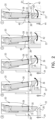
- FIG. 2 is a schematic illustration showing various different positions of latch 28 during coupling of tube cassette 22 to pump 20, in accordance with some applications of the present invention.
- Fig. 2 shows a transition of the latch position from position (A), prior to tube cassette 22 being coupled to pump 20, through to position (E), in which tube cassette 22 is locked in the preset position with respect to pump 20.
- Coupling of tube cassette 22 to pump 20 is typically done by pushing tube cassette 22 in a first direction, toward pump 20.
- latches 28' and 28'' may be engaged one after the other, i.e., tube cassette 22 is coupled to pump 20 by engaging one of the latches and then pivoting tube cassette 22 in a direction toward pump 20 to engage the other latch.
- latches 28' and 28'' are identical in shape and disposed in a generally mirror-image orientation with respect to each other so it does not matter which latch is engaged first and which latch is engaged after pivoting tube cassette 22 toward pump 20.
- tube cassette 22 may alternatively or additionally be pushed toward pump 20 such that both latches are engaged simultaneously.
- Position (A) of latch 28 represents an initial position of latch 28, prior to tube cassette 22 being coupled to pump 20.
- coupling of tube cassette 22 to pump 20 is via movement of tube cassette 22 in a first direction, toward pump 20.
- Arrow 34 represents motion of tube cassette 22 in the first direction.
- tube cassette 22 moves in the first direction (e.g., due to a user pushing tube cassette 22 into pump 20)
- tube cassette 22 pushes latch 28 to rotate, in a first rotational direction from the initial position (A) to an angular position (B) (that is, the angular position is at a non-zero angle from the initial position) .
- latch 28 continues its rotation in the first rotational direction until position (C) is reached, representing an open position of latch 28.
- Curved arrow 36 in positions (B) and (C) represents the first rotational direction in which latch 28 rotates in the transition from position (A) to position (B) and subsequently from position (B) to position (C), i.e., to the open position of latch 28.
- latch 28, e.g., lower latch surface 30, has not yet engaged with locking surface 26.
- pump 20 ejects tube cassette 22 by pushing infusion tubing 24, which in turn pushes tube cassette 22 from pump 20. If tube cassette 22 is released prior to reaching a threshold position, pump 20 will eject tube cassette 22. In order to not be ejected by pump 20, tube cassette 22 has to move, in the first direction, past the threshold position.
- pump 20 and tube cassette 22 are designed so as to allow "over-travel" of tube cassette 22 in the first direction, thus ensuring that tube cassette 22 moves past the threshold position, allowing latch 28, e.g., lower latch surface 30, to engage locking surface 26.
- a mechanical stop 38 is disposed within pump 20 and positioned to stop the motion of tube cassette 22 in the first direction.
- the external force pushing tube cassette 22 in the first direction is able to continue pushing until motion of tube cassette 22 in the first direction is stopped by mechanical stop 38.
- tube cassette 22 has moved past the preset position with respect to pump 20, i.e., has "over-traveled" in the first direction.
- the preset position with respect to pump 20 is represented by dashed line 40 in Fig. 2 .
- latch 28 e.g., latches 28' and 28"
- latch 28 lock tube cassette 22 in the preset position with respect to pump 20.
- latch 28 allows motion of tube cassette 22 past the preset position in the first direction.
- latch 28 Upon engagement of latch 28, e.g., lower latch surface 30, with locking surface 26, latch 28, being typically spring-loaded, automatically moves from its open position, position (C), to a cassette-withdrawal-inhibiting position, position (D). During this transition from the open position to the cassette-withdrawal-inhibiting position, latch 28 switches direction and rotates in a second rotational direction, opposite the first rotational direction, represented by curved arrow 42 in position (D).
- the cassette-withdrawal-inhibiting position of latch 28 is between the initial position of latch 28 prior to tube cassette 22 being coupled to pump 20 (position (A)) and the open position of latch 28 (position (C)), i.e., latch 28 inhibits cassette-withdrawal even before latch 28 returns to its initial position.
- position (A) the initial position of latch 28 prior to tube cassette 22 being coupled to pump 20
- position (C) the open position of latch 28
- latch 28 inhibits cassette-withdrawal even before latch 28 returns to its initial position.
- latch 28 locks tube cassette 22 in the preset position by pushing tube cassette 22 (further described hereinbelow) in a second direction, opposite the first direction, e.g., away from pump 20, such that tube cassette 22 moves from past the preset position to the preset position, at dashed line 40.
- Arrow 44 represents motion of tube cassette 22 in the second direction as tube cassette 22 is pushed by latch 28, e.g., by latches 28' and 28'', back to the preset position.
- latch 28 continues its rotation in the second rotational direction, such that latch 28 returns to the initial position of latch 28 subsequently to the pushing of tube cassette 22 in the second direction, such as is shown in position (E) of Fig. 2 .
- latch 28 pushes tube cassette 22 in the second direction via engagement between upper latch surface 32 of latch 28 and an upper locking surface 46 of tube cassette 22 (i.e., locking surface 26 is a lower locking surface 26 and tube cassette 22 is shaped to define an upper locking surface 46 as well).
- the external force that was maintaining the motion of tube cassette 22 in the first direction e.g., the external force being generated by the user pushing the tube cassette into pump 20
- latch 28, being typically spring-loaded, continues its rotational motion back towards the initial position of latch 28.
- upper latch surface 32 pushes upper locking surface 46 in the second direction, e.g., away from pump 20.
- lower latch surface 30 and upper latch surface 32 are shaped to define the preset position of tube cassette 22, such that subsequently to latch 28 pushing tube cassette 22 into the preset position, (a) movement of tube cassette 22 in the first direction is inhibited by upper latch surface 32, and (b) movement of tube cassette 22 in the second direction is inhibited by lower latch surface 30.
- movement being prohibited is taken to mean that movement of larger than 20 microns is inhibited.
- latch 28 e.g., latches 28' and 28''
- latch 28 e.g., latches 28' and 28''
- an external force pushes on tube cassette 22 in the first direction, e.g., towards pump 20
- the distance between the pressing surface inside pump 20 and infusion tubing 24 will decrease, which in turn may cause a bolus of fluid to be delivered to the subject and/or an inaccuracy in the volume of fluid delivered to the subject.
- latch 28 e.g., latches 28' and 28''
- the distance between the pressing surface and infusion tubing 24 may increase, resulting in potential under-delivery of the fluid to the subject.
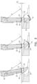
- FIG. 3 is a schematic illustration showing various different positions of latch 28, in accordance with some applications of the present invention. It is desirable that as soon as latch 28 (e.g., upper latch surface 32) has pushed tube cassette 22 into the preset position, any continued rotational movement of latch 28 in the second rotational direction (i.e., as latch 28 returns to its initial position) not change preset distance D1 between tube cassette 22 and mechanical stop 38.
- latch 28 e.g., upper latch surface 32
- tube cassette 22 is still (a) inhibited from falling out of pump 20 due to latch 28 having automatically moved to the cassette-withdrawal-inhibiting position, and (b) locked in the preset position due to latch 28 not changing the distance between tube cassette 22 and mechanical stop 38 during its rotational motion in the second direction subsequent to pushing tube cassette 22 into the preset position.
- distance D1 in Fig. 3 represents the same preset distance D1 shown in Fig. 2 between tube cassette 22 and mechanical stop 38 when latch 28 is in position (E).
- lower locking surface 26 having radius of curvature R that is substantially equal to a distance D2 between an axis of rotation 48 of latch 28 and lower latch surface 26, such that, subsequently to upper latch surface 32 pushing tube cassette 22 into the preset position, as lower latch surface 30 continues to swing rotationally inwards towards pump 20 the motion of lower latch surface 30 follows the radius of curvature R of lower locking surface 26.
- the radius of curvature R being substantially equal to distance D2 ensures that as latch surface 30 continues to swing rotationally inwards, towards pump 20, a distance of typically no more than 20 microns is maintained between lower latch surface 30 and lower locking surface 26.
- tube cassette 22 is shaped to define an orientation key to ensure that tube cassette 22 can only be inserted into pump 20 in one orientation of tube cassette 22 with respect to pump 20.
- a first cavity 50 in tube cassette 22 may engage with a corresponding protrusion on pump 20 (or vice versa) such that if a user tried to insert tube cassette 22 into pump 20 in a different orientation, the protrusion on pump 20 would inhibit the insertion.
- a side-to-side positioning key ensures that once tube cassette 22 is locked in the preset position with respect to pump 20, not only is the distance between the pressing surface inside pump 20 and infusion tubing 24 tightly defined, but also the longitudinal site along infusion tubing 24 at which the pressing surface presses on infusion tubing 24.
- a second cavity 52 in tube cassette 22 may engage with a corresponding protrusion on pump 20 (or vice versa) to ensure that tube cassette 22 cannot move from side-to-side with respect to pump 20 when tube cassette 22 is coupled to pump 20.
Landscapes
- Health & Medical Sciences (AREA)
- Vascular Medicine (AREA)
- Engineering & Computer Science (AREA)
- Anesthesiology (AREA)
- Biomedical Technology (AREA)
- Heart & Thoracic Surgery (AREA)
- Hematology (AREA)
- Life Sciences & Earth Sciences (AREA)
- Animal Behavior & Ethology (AREA)
- General Health & Medical Sciences (AREA)
- Public Health (AREA)
- Veterinary Medicine (AREA)
- Infusion, Injection, And Reservoir Apparatuses (AREA)
Description
- The present application claims the priority of
US 62/814,001 to Yachnis et al., filed March 5, 2019 - The present invention relates generally to medical fluid-delivery devices, and more specifically to infusion pumps.
- Pumps are often used in the medical industry for delivering fluids, e.g., drugs, or diagnostic fluids, to subjects. One type of medical pump is an infusion pump, used to infuse a fluid into a subject's circulatory system via infusion tubing. Some infusion pumps include a valve, or system of valves, that may occlude flow within the infusion tubing by pressing on the outside of the fluid-filled infusion tubing. Often infusion pumps engage with the infusion tubing via a tube cassette. Relevant prior art can be found in
US 8 986 252 ,US 4 735 558 ,US 6 231 320 , andUS 5 755 691 . - Infusion pumps often engage with infusion tubing via a tube cassette that receives the infusion tubing and is subsequently coupled to the infusion pump. The following are some properties and phenomena that may occur in infusion pumps that utilize tube cassettes:
- In some infusion pumps, the tube cassette has to be inserted in a particular way, e.g., starting from a particular side of the pump and pivoting down towards the opposite side of the pump.
- In some infusion pumps, the coupling of the tube cassette and the pump may have a region of meta-stability, at which in the absence of any force external to the tube cassette, the tube cassette may be engaged with the pump but in an unstable manner, whereby the tube cassette may pop out at any point.
- In some infusion pumps, during delivery of the fluid to the subject, if an external force is applied to the tube cassette, pressure may be put on the infusion tubing causing either a bolus delivery to the patient, or inaccuracy of the delivery volume.
- In light of these considerations, an infusion pump and tube cassette are provided, in accordance with some applications of the present invention. The tube cassette receives the infusion tubing and is removably couplable to the pump. The pump and tube cassette have a locking system that includes a locking surface on the tube cassette, a latch on the pump, and a mechanical stop disposed within the pump. When the tube cassette is coupled to the pump, the latch lockingly engages with the locking surface in such a way as to ensure that, upon full insertion of the tube cassette into the pump, the latch (a) automatically moves to a cassette-withdrawal-inhibiting position, avoiding a possibly meta-stable connection between the tube cassette and the pump, and (b) locks the tube cassette in a preset position with respect to the pump.
- As the tube cassette is inserted into the pump, motion of the tube cassette in a first direction, toward the pump, can continue all the way until the tube cassette is stopped by the mechanical stop. The mechanical stop is positioned to stop the motion of the tube cassette once the tube cassette has "over-traveled," i.e., has moved past the preset position. The "over-travel" of the tube cassette ensures that the latch fully engages the locking surface, without the latch potentially getting stuck in a meta-stable position. After the latch has achieved a state of making sure the cassette cannot fall out of the pump, the latch then locks the tube cassette in the preset position by pushing the tube cassette back from past the preset position (where it was stopped by the mechanical stop) to the preset position.
- The invention is defined by the appended claims. In particular, there is therefore provided, in accordance with some applications of the present invention, apparatus for delivering a fluid to a subject through infusion tubing, the apparatus including:
- (A) a tube cassette configured to receive the infusion tubing, the tube cassette shaped to define a locking surface;
- (B) a pump including a latch,
- (i) the tube cassette being configured to be removably coupled to the pump, and
- (ii) the latch being configured to (a) engage with the locking surface and (b) lock the tube cassette in a preset position with respect to the pump when the tube cassette is coupled to the pump; and
- (C) a mechanical stop disposed within the pump,
- (i) the mechanical stop being positioned to stop motion of the tube cassette in a first direction, such that when the motion of the tube cassette in the first direction is stopped by the mechanical stop, the tube cassette has moved past the preset position in the first direction, and
- (ii) the latch being configured to:
- (a) until the motion of the tube cassette is stopped by the mechanical stop, allow motion of the tube cassette past the preset position in the first direction,
- (b) automatically move from an open position to a cassette-withdrawal-inhibiting position once the tube cassette moves in the first direction past a threshold position, allowing the latch to engage with the locking surface, and
- (c) subsequently, lock the tube cassette in the preset position by pushing the tube cassette in a second direction opposite the first direction, from past the preset position to the preset position.
- For some applications, the latch is a spring-loaded latch.
- For some applications, the latch is configured to, during the coupling of the tube cassette to the pump, sequentially:
- (a) rotate in a first rotational direction during a transition from (i) an initial position prior to the tube cassette being coupled to the pump to (ii) the open position, during motion of the tube cassette in the first direction,
- (b) rotate in a second rotational direction, opposite the first rotational direction, in the transition from (i) the open position to (ii) the cassette-withdrawal-inhibiting position, and
- (c) continue rotation in the second rotational direction during the pushing of the tube cassette in the second direction from past the preset position to the preset position, such that the latch returns to the initial position subsequently to the pushing of the tube cassette in the second direction.
- For some applications, the cassette-withdrawal-inhibiting position of the latch is between (a) an initial position of the latch prior to the tube cassette being coupled to the pump and (b) the open position.
- For some applications, the pump and the tube cassette are configured such that, in the absence of a sufficient external force maintaining the motion of the tube cassette in the first direction prior to the engagement of the latch with the locking surface, the pump is configured to eject the tube cassette by pushing the infusion tubing which in turn pushes the tube cassette from the pump.
- For some applications, the latch includes a lower latch surface, the lower latch surface being configured to engage with the locking surface of the tube cassette, the lower locking surface having a radius of curvature that is substantially equal to a distance between an axis of rotation of the latch and the lower latch surface.
- For some applications:
- the locking surface is a lower locking surface, and the tube cassette is further shaped to define an upper locking surface, opposite the lower locking surface, and
- the latch includes a lower latch surface and an upper latch surface, (a) the lower latch surface being configured to engage with the lower locking surface, and (b) the upper latch surface being configured to engage with the upper locking surface when the tube cassette is coupled to the pump, such that:
- (i) engagement between the lower latch surface and the lower locking surface inhibits cassette withdrawal when the latch moves from the open position to the cassette-withdrawal-inhibiting position, and
- (ii) subsequently, the upper latch surface pushes the tube cassette in the second direction by pushing on the upper locking surface of the tube cassette.
- For some applications, the lower and upper latch surfaces are shaped to define the preset position of the tube cassette, such that subsequently to the upper latch surface pushing the tube cassette in the second direction, (a) movement of the tube cassette in the first direction is inhibited by the upper latch surface, and (b) movement of the tube cassette in the second direction is inhibited by the lower latch surface.
- For some applications, the lower locking surface is shaped to define a radius of curvature that is substantially equal to a distance between an axis of rotation of the latch and the lower latch surface.
- For some applications:
- the locking surface is a first locking surface and the tube cassette is shaped to define a second locking surface, and
- the latch is a first latch and the pump further includes a second latch, the second latch being configured to (a) lockingly engage with the second locking surface and (b) lock the tube cassette in the preset position with respect to the pump when the tube cassette is coupled to the pump.
- For some applications, the first and second latches are disposed on opposite sides of the pump.
- The present invention will be more fully understood from the following detailed description of applications thereof, taken together with the drawings, in which:
-
-
Fig. 1A is a schematic illustration of a pump with a tube cassette coupled to the pump, in accordance with some applications of the present invention; -
Fig. 1B is a schematic illustration of a latch of the pump, in accordance with some applications of the present invention; -
Fig. 2 is a schematic illustration showing various different positions of a latch during coupling of the tube cassette to the pump, in accordance with some applications of the present invention; -
Fig. 3 is a schematic illustration showing various different positions of the latch, in accordance with some applications of the present invention; and -
Figs. 4A-4B are schematic illustrations of the tube cassette, in accordance with some applications of the present invention. - Reference is now made to
Fig. 1A , which is a schematic illustration of apump 20 with atube cassette 22 coupled to the pump, in accordance with some applications of the present invention.Pump 20 is typically an infusion pump, e.g., a volumetric infusion pump, or a peristaltic infusion pump, that delivers fluid, e.g., drugs or diagnostic fluids, to subjects throughinfusion tubing 24.Tube cassette 22 receivesinfusion tubing 24 and is removably couplable to pump 20, such thatpump 20 engages withinfusion tubing 24 viatube cassette 22. - Typically,
tube cassette 22 is shaped to define at least one lockingsurface 26, e.g., a first locking surface 26' and a second locking surface 26'' respectively on either side oftube cassette 22. Typically, pump 20 comprises at least onelatch 28, e.g., a first latch 28' and a second latch 28'' disposed respectively on either side ofpump 20. Astube cassette 22 is coupled to pump 20, e.g., inserted intopump 20 by being pushed intopump 20 in a first direction towardpump 20, latch 28 lockingly engages a lockingsurface 26 oftube cassette 22. Typically, such as is shown inFig. 1A , first latch 28' engages with first locking surface 26' and second latch 28'' engages with second locking surface 26''. - Subsequently to the
latch 28 engaging with lockingsurface 26, latch 28 (e.g., latches 28' and 28'') lockstube cassette 22 in a preset position with respect to pump 20, as further described hereinbelow with reference toFigs. 2 and3 .Fig. 1A showstube cassette 22 already locked in the preset position after having been coupled to pump 20. For some applications, as further described hereinbelow, eachlatch 28 has alower latch surface 30 and anupper latch surface 32. - Reference is now made to
Fig. 1B , which is a schematic illustration oflatch 28, in accordance with some applications of the present invention. For some applications, latches 28 are spring-loaded latches. As further described hereinbelow,tube cassette 22 is coupled to pump 20 typically by a user pushingtube cassette 22 intopump 20. In turn,tube cassette 22 pushes latch 28 to rotate, in a first rotational direction, represented bycurved arrow 36.Spring 29 spring-loads latch 28, such that aslatch 28 rotates in the first rotational direction,spring 29 biases latch 28 to return to its initial position by rotating in a second rotational direction, opposite the first rotational direction (represented bycurved arrows 42 inFigs. 2 and3 ). - Reference is now made to
Fig. 2 , which is a schematic illustration showing various different positions oflatch 28 during coupling oftube cassette 22 to pump 20, in accordance with some applications of the present invention.Fig. 2 shows a transition of the latch position from position (A), prior totube cassette 22 being coupled to pump 20, through to position (E), in whichtube cassette 22 is locked in the preset position with respect to pump 20. - Coupling of
tube cassette 22 to pump 20 is typically done by pushingtube cassette 22 in a first direction, towardpump 20. For some applications, latches 28' and 28'' may be engaged one after the other, i.e.,tube cassette 22 is coupled to pump 20 by engaging one of the latches and then pivotingtube cassette 22 in a direction towardpump 20 to engage the other latch. Typically, latches 28' and 28'' are identical in shape and disposed in a generally mirror-image orientation with respect to each other so it does not matter which latch is engaged first and which latch is engaged after pivotingtube cassette 22 towardpump 20. Thus,tube cassette 22 may alternatively or additionally be pushed towardpump 20 such that both latches are engaged simultaneously. - Position (A) of
latch 28 represents an initial position oflatch 28, prior totube cassette 22 being coupled to pump 20. As described hereinabove, coupling oftube cassette 22 to pump 20 is via movement oftube cassette 22 in a first direction, towardpump 20.Arrow 34 represents motion oftube cassette 22 in the first direction. Astube cassette 22 moves in the first direction (e.g., due to a user pushingtube cassette 22 into pump 20),tube cassette 22 pushes latch 28 to rotate, in a first rotational direction from the initial position (A) to an angular position (B) (that is, the angular position is at a non-zero angle from the initial position) . Astube cassette 22 continues to move further in the first direction, latch 28 continues its rotation in the first rotational direction until position (C) is reached, representing an open position oflatch 28.Curved arrow 36 in positions (B) and (C) represents the first rotational direction in which latch 28 rotates in the transition from position (A) to position (B) and subsequently from position (B) to position (C), i.e., to the open position oflatch 28. - As shown in position (C),
latch 28, e.g.,lower latch surface 30, has not yet engaged with lockingsurface 26. Typically, prior to engagement oflatch 28, e.g.,lower latch surface 30, with lockingsurface 26, in the absence of a sufficient external force maintaining the motion oftube cassette 22 in the first direction, pump 20 ejectstube cassette 22 by pushinginfusion tubing 24, which in turn pushestube cassette 22 frompump 20. Iftube cassette 22 is released prior to reaching a threshold position, pump 20 will ejecttube cassette 22. In order to not be ejected bypump 20,tube cassette 22 has to move, in the first direction, past the threshold position. - Thus, for some applications, pump 20 and
tube cassette 22 are designed so as to allow "over-travel" oftube cassette 22 in the first direction, thus ensuring thattube cassette 22 moves past the threshold position, allowinglatch 28, e.g.,lower latch surface 30, to engage lockingsurface 26. Amechanical stop 38 is disposed withinpump 20 and positioned to stop the motion oftube cassette 22 in the first direction. Thus, the external force pushingtube cassette 22 in the first direction is able to continue pushing until motion oftube cassette 22 in the first direction is stopped bymechanical stop 38. When the motion oftube cassette 22 in the first direction is stopped bymechanical stop 38,tube cassette 22 has moved past the preset position with respect to pump 20, i.e., has "over-traveled" in the first direction. The preset position with respect to pump 20 is represented by dashedline 40 inFig. 2 . - The "over-travel" position where the motion of
tube cassette 22 is stopped bymechanical stop 38 is represented by position (D) inFig. 2 . As described hereinabove,latch 28, e.g., latches 28' and 28", locktube cassette 22 in the preset position with respect to pump 20. However, until the motion oftube cassette 22 is stopped bymechanical stop 38,latch 28 allows motion oftube cassette 22 past the preset position in the first direction. - Upon engagement of
latch 28, e.g.,lower latch surface 30, with lockingsurface 26,latch 28, being typically spring-loaded, automatically moves from its open position, position (C), to a cassette-withdrawal-inhibiting position, position (D). During this transition from the open position to the cassette-withdrawal-inhibiting position, latch 28 switches direction and rotates in a second rotational direction, opposite the first rotational direction, represented bycurved arrow 42 in position (D). - Typically, the cassette-withdrawal-inhibiting position of
latch 28 is between the initial position oflatch 28 prior totube cassette 22 being coupled to pump 20 (position (A)) and the open position of latch 28 (position (C)), i.e., latch 28 inhibits cassette-withdrawal even beforelatch 28 returns to its initial position. The combination of the following three characteristics of the coupling oftube cassette 22 to pump 20 results in substantially no chance of a meta-stable coupling betweentube cassette 22 and pump 20, i.e., wheretube cassette 22 is coupled to pump 20 but in an unstable manner: - (a) in the absence of sufficient force to keep
tube cassette 22 moving, pump 20ejecting tube cassette 22 prior to engagement oflatch 28 and lockingsurface 26, - (b) allowing "over-travel" to ensure engagement of
latch 28 and lockingsurface 26 astube cassette 22 is pushed towardpump 20, and - (c) latch 28 automatically moving to the cassette-withdrawal-inhibiting position (prior to latch 28 finishing closing), upon engagement of
latch 28 with lockingsurface 26. - Subsequently to latch 28 moving to the cassette-withdrawal-inhibiting position, latch 28
locks tube cassette 22 in the preset position by pushing tube cassette 22 (further described hereinbelow) in a second direction, opposite the first direction, e.g., away frompump 20, such thattube cassette 22 moves from past the preset position to the preset position, at dashedline 40.Arrow 44 represents motion oftube cassette 22 in the second direction astube cassette 22 is pushed bylatch 28, e.g., by latches 28' and 28'', back to the preset position. During this pushing oftube cassette 22 in the second direction, latch 28 continues its rotation in the second rotational direction, such thatlatch 28 returns to the initial position oflatch 28 subsequently to the pushing oftube cassette 22 in the second direction, such as is shown in position (E) ofFig. 2 . - For some applications, latch 28 pushes
tube cassette 22 in the second direction via engagement betweenupper latch surface 32 oflatch 28 and anupper locking surface 46 of tube cassette 22 (i.e., lockingsurface 26 is alower locking surface 26 andtube cassette 22 is shaped to define anupper locking surface 46 as well). Subsequently to the motion oftube cassette 22 being stopped bymechanical stop 38, the external force that was maintaining the motion oftube cassette 22 in the first direction (e.g., the external force being generated by the user pushing the tube cassette into pump 20) is typically terminated. In the absence of the external force, latch 28, being typically spring-loaded, continues its rotational motion back towards the initial position oflatch 28. During this continued rotational motion in the second rotational direction,upper latch surface 32 pushesupper locking surface 46 in the second direction, e.g., away frompump 20. - Typically,
lower latch surface 30 andupper latch surface 32 are shaped to define the preset position oftube cassette 22, such that subsequently to latch 28 pushingtube cassette 22 into the preset position, (a) movement oftube cassette 22 in the first direction is inhibited byupper latch surface 32, and (b) movement oftube cassette 22 in the second direction is inhibited bylower latch surface 30. As used in the present application including in the claims, movement being prohibited is taken to mean that movement of larger than 20 microns is inhibited. The preset position oftube cassette 22, in turn, defines a preset distance D1 betweentube cassette 22 andmechanical stop 38, and a preset distance between a pressing surface inside pump 20 (not shown) that repeatedly presses oninfusion tubing 24 to deliver the fluid to the subject. - The locking of
tube cassette 22 in the preset position bylatch 28, e.g., latches 28' and 28'', inhibits any external forces that may act ontube cassette 22 during delivery of the fluid from affecting the delivery of the fluid, by affecting the distance between the pressing surface andinfusion tubing 24. For example, in the absence of latch 28 (e.g., latches 28' and 28'') lockingtube cassette 22 in the preset position, if an external force pushes ontube cassette 22 in the first direction, e.g., towardspump 20, the distance between the pressing surface insidepump 20 andinfusion tubing 24 will decrease, which in turn may cause a bolus of fluid to be delivered to the subject and/or an inaccuracy in the volume of fluid delivered to the subject. Similarly, for example, in the absence of latch 28 (e.g., latches 28' and 28'') lockingtube cassette 22 in the preset position, if an external force pullstube cassette 22 in the second direction, e.g., away frompump 20, the distance between the pressing surface andinfusion tubing 24 may increase, resulting in potential under-delivery of the fluid to the subject. - Reference is now made to
Fig. 3 , which is a schematic illustration showing various different positions oflatch 28, in accordance with some applications of the present invention. It is desirable that as soon as latch 28 (e.g., upper latch surface 32) has pushedtube cassette 22 into the preset position, any continued rotational movement oflatch 28 in the second rotational direction (i.e., aslatch 28 returns to its initial position) not change preset distance D1 betweentube cassette 22 andmechanical stop 38. This is advantageous, for example, iflatch 28 does not return to its initial position,tube cassette 22 is still (a) inhibited from falling out ofpump 20 due to latch 28 having automatically moved to the cassette-withdrawal-inhibiting position, and (b) locked in the preset position due to latch 28 not changing the distance betweentube cassette 22 andmechanical stop 38 during its rotational motion in the second direction subsequent to pushingtube cassette 22 into the preset position. (Althoughpump 20 is not shown inFig. 3 , distance D1 inFig. 3 represents the same preset distance D1 shown inFig. 2 betweentube cassette 22 andmechanical stop 38 whenlatch 28 is in position (E).). - For some applications, this is achieved by
lower locking surface 26 having radius of curvature R that is substantially equal to a distance D2 between an axis ofrotation 48 oflatch 28 andlower latch surface 26, such that, subsequently toupper latch surface 32 pushingtube cassette 22 into the preset position, aslower latch surface 30 continues to swing rotationally inwards towardspump 20 the motion oflower latch surface 30 follows the radius of curvature R oflower locking surface 26. Typically, the radius of curvature R being substantially equal to distance D2 ensures that aslatch surface 30 continues to swing rotationally inwards, towardspump 20, a distance of typically no more than 20 microns is maintained betweenlower latch surface 30 andlower locking surface 26. Thus, at no point between (a) whentube cassette 22 is pushed into the preset position and (b) whenlatch 28 returns to the initial position, doeslower latch surface 30 push onlower locking surface 26 in the first direction, e.g., towardpump 20. Yet, at substantially every point during the continued rotation in the second direction, iflatch 28 were to stop its motion,lower latch surface 30 would still inhibit movement oftube cassette 22 in the second direction, as described hereinabove. - Reference is now made to
Figs. 4A and 4B , which are schematic illustration oftube cassette 22, in accordance with some applications of the present invention. For some applications,tube cassette 22 is shaped to define an orientation key to ensure thattube cassette 22 can only be inserted intopump 20 in one orientation oftube cassette 22 with respect to pump 20. For example, afirst cavity 50 intube cassette 22 may engage with a corresponding protrusion on pump 20 (or vice versa) such that if a user tried to inserttube cassette 22 intopump 20 in a different orientation, the protrusion onpump 20 would inhibit the insertion. For some applications, a side-to-side positioning key ensures that oncetube cassette 22 is locked in the preset position with respect to pump 20, not only is the distance between the pressing surface insidepump 20 andinfusion tubing 24 tightly defined, but also the longitudinal site alonginfusion tubing 24 at which the pressing surface presses oninfusion tubing 24. For example, asecond cavity 52 intube cassette 22 may engage with a corresponding protrusion on pump 20 (or vice versa) to ensure thattube cassette 22 cannot move from side-to-side with respect to pump 20 whentube cassette 22 is coupled to pump 20. - It will be appreciated by persons skilled in the art that the present invention is not limited to what has been particularly shown and described hereinabove. Rather, the scope of the present invention is defined by the appended claims.
Claims (11)
- Apparatus for delivering a fluid to a subject through infusion tubing (24), the apparatus comprising:(A) a tube cassette (22) configured to receive the infusion tubing (24), the tube cassette (22) shaped to define a locking surface (26) ;(B) a pump (20) comprising a latch (28),(i) the tube cassette (22) being configured to be removably coupled to the pump (20), and(ii) the latch (28) being configured to (a) engage with the locking surface (26) and (b) lock the tube cassette (22) in a preset position with respect to the pump (20) when the tube cassette (22) is coupled to the pump (20); and(C) a mechanical stop (38) disposed within the pump (20), characterized in that:(i) the mechanical stop (38) is positioned to stop motion of the tube cassette (22) in a first direction, such that when the motion of the tube cassette (22) in the first direction is stopped by the mechanical stop (38), the tube cassette (22) has moved past the preset position in the first direction, and(ii) the latch (28) is configured to:(a) until the motion of the tube cassette (22) is stopped by the mechanical stop (38), allow motion of the tube cassette (22) past the preset position in the first direction,(b) automatically move from an open position to a cassette-withdrawal-inhibiting position once the tube cassette (22) moves in the first direction past a threshold position, allowing the latch (28) to engage with the locking surface (26), and(c) subsequently, lock the tube cassette (22) in the preset position by pushing the tube cassette (22) in a second direction opposite the first direction, from past the preset position to the preset position.
- The apparatus according to claim 1, wherein the latch (28) is a spring-loaded latch.
- The apparatus according to claim 1, wherein the latch (28) is configured to, during the coupling of the tube cassette (22) to the pump (20), sequentially:(a) rotate in a first rotational direction during a transition from (i) an initial position prior to the tube cassette (22) being coupled to the pump (20) to (ii) the open position, during motion of the tube cassette (22) in the first direction,(b) rotate in a second rotational direction, opposite the first rotational direction, in the transition from (i) the open position to (ii) the cassette-withdrawal-inhibiting position, and(c) continue rotation in the second rotational direction during the pushing of the tube cassette (22) in the second direction from past the preset position to the preset position, such that the latch (28) returns to the initial position subsequently to the pushing of the tube cassette (22) in the second direction.
- The apparatus according to claim 1, wherein the cassette-withdrawal-inhibiting position of the latch (28) is between (a) an initial position of the latch prior to the tube cassette (22) being coupled to the pump (20) and (b) the open position.
- The apparatus according to claim 1, wherein the pump (20) and the tube cassette (22) are configured such that, in the absence of a sufficient external force maintaining the motion of the tube cassette (22) in the first direction prior to the engagement of the latch (28) with the locking surface (26), the pump is configured to eject the tube cassette (22) by pushing the infusion tubing (22) which in turn pushes the tube cassette (22) from the pump (20).
- The apparatus according to claim 1, wherein the latch (28) comprises a lower latch surface (30), the lower latch surface (30) being configured to engage with the locking surface (26) of the tube cassette (22), the lower latch surface (30) having a radius of curvature (R) that is substantially equal to a distance (D2) between an axis of rotation (48) of the latch (28) and the lower latch surface (30).
- The apparatus according to any one of claims 1-6, wherein:the locking surface (26) is a lower locking surface, and the tube cassette (22) is further shaped to define an upper locking surface (46), opposite the lower locking surface, andthe latch (28) comprises a lower latch surface (30) and an upper latch surface (32), (a) the lower latch surface (30) being configured to engage with the lower locking surface, and (b) the upper latch surface (32) being configured to engage with the upper locking surface (46) when the tube cassette (22) is coupled to the pump (20), such that:(i) engagement between the lower latch surface (30) and the lower locking surface inhibits cassette (22) withdrawal when the latch (28) moves from the open position to the cassette-withdrawal-inhibiting position, and(ii) subsequently, the upper latch surface (32) pushes the tube cassette (22) in the second direction by pushing on the upper locking surface (46) of the tube cassette (22).
- The apparatus according to claim 7, wherein the lower and upper latch surfaces (30, 32) are shaped to define the preset position of the tube cassette (22), such that subsequently to the upper latch surface (32) pushing the tube cassette (22) in the second direction, (a) movement of the tube cassette (22) in the first direction is inhibited by the upper latch surface (32), and (b) movement of the tube cassette (22) in the second direction is inhibited by the lower latch surface (30).
- The apparatus according to claim 7, wherein the lower locking surface is shaped to define a radius of curvature (R) that is substantially equal to a distance (D2) between an axis of rotation (48) of the latch (28) and the lower latch surface (30).
- The apparatus according to any one of claims 1-6, wherein:the locking surface (26) is a first locking surface (26')and the tube cassette (22) is shaped to define a second locking surface (26"), andthe latch (28) is a first latch (28') and the pump (20) further comprises a second latch (28"), the second latch (28") being configured to (a) lockingly engage with the second locking surface (26") and (b) lock the tube cassette (22) in the preset position with respect to the pump (20) when the tube cassette (22) is coupled to the pump (20).
- The apparatus according to claim 10, wherein the first and second latches (28', 28") are disposed on opposite sides of the pump (20).
Applications Claiming Priority (2)
| Application Number | Priority Date | Filing Date | Title |
|---|---|---|---|
| US201962814001P | 2019-03-05 | 2019-03-05 | |
| PCT/IL2020/050247 WO2020178825A1 (en) | 2019-03-05 | 2020-03-04 | Infusion pump cassette latch |
Publications (2)
| Publication Number | Publication Date |
|---|---|
| EP3934715A1 EP3934715A1 (en) | 2022-01-12 |
| EP3934715B1 true EP3934715B1 (en) | 2024-08-14 |
Family
ID=69845497
Family Applications (1)
| Application Number | Title | Priority Date | Filing Date |
|---|---|---|---|
| EP20712057.7A Active EP3934715B1 (en) | 2019-03-05 | 2020-03-04 | Infusion pump cassette latch |
Country Status (4)
| Country | Link |
|---|---|
| US (1) | US12186528B2 (en) |
| EP (1) | EP3934715B1 (en) |
| ES (1) | ES2989157T3 (en) |
| WO (1) | WO2020178825A1 (en) |
Families Citing this family (2)
| Publication number | Priority date | Publication date | Assignee | Title |
|---|---|---|---|---|
| EP3664866B1 (en) | 2017-08-10 | 2022-01-05 | West Pharma. Services Il, Ltd. | Injector cartridge door locking mechanism |
| US12539360B2 (en) | 2023-03-02 | 2026-02-03 | B. Braun Medical Inc. | Latch for capturing and securing a cassette to a medical device |
Family Cites Families (152)
| Publication number | Priority date | Publication date | Assignee | Title |
|---|---|---|---|---|
| US3379950A (en) | 1965-07-06 | 1968-04-23 | Bailey Meter Co | Load control circuit including means responsive to load current in excess of a predetermined amount for increasing said load current |
| CA1081316A (en) | 1976-11-12 | 1980-07-08 | Canadian General Electric Company Limited | Power control of a stalling motor |
| US4236880A (en) | 1979-03-09 | 1980-12-02 | Archibald Development Labs, Inc. | Nonpulsating IV pump and disposable pump chamber |
| US4391600A (en) | 1979-03-09 | 1983-07-05 | Avi, Inc. | Nonpulsating IV pump and disposable pump chamber |
| US4314567A (en) | 1979-09-24 | 1982-02-09 | Imed Corporation | Drop controller |
| HU190171B (en) | 1983-10-10 | 1986-08-28 | Labor Mueszeripari Muevek,Hu | Peristaltic pump |
| DE3581704D1 (en) | 1984-10-19 | 1991-03-14 | Pharmacia Deltec Inc | MEDICINE DISPENSING SYSTEM. |
| US4650469A (en) | 1984-10-19 | 1987-03-17 | Deltec Systems, Inc. | Drug delivery system |
| US4735558A (en) * | 1986-04-08 | 1988-04-05 | Staar Surgical Company | Peristaltic pump latching mechanism |
| US5246347A (en) | 1988-05-17 | 1993-09-21 | Patients Solutions, Inc. | Infusion device with disposable elements |
| DE3842404A1 (en) | 1988-12-16 | 1990-06-21 | Fresenius Ag | DEVICE FOR MEASURING THE INTERNAL DIAMETER OF HOSES MADE OF FLEXIBLE MATERIAL |
| US5096385A (en) | 1989-11-08 | 1992-03-17 | Ivac Corporation | Method and system for upstream occlusion detection |
| US5018945A (en) | 1989-12-14 | 1991-05-28 | Baxter International Inc. | Accurate peristaltic pump |
| US5116203A (en) | 1990-03-15 | 1992-05-26 | Abbott Laboratories | Detecting occlusion of proximal or distal lines of an IV pump |
| CA2064134A1 (en) | 1991-04-23 | 1992-10-24 | Gary A. Thill | Free flow prevention system for infusion pump |
| DE4119734A1 (en) | 1991-06-14 | 1992-12-17 | Mettler Toledo Ag | DEVICE FOR REDUCING FORCE IN A FORCE MEASURING DEVICE, IN PARTICULAR A SCALE |
| US5567119A (en) | 1993-10-28 | 1996-10-22 | Sims Deltec, Inc. | Bag/syringe enclosure arrangements and methods |
| US5807075A (en) | 1993-11-23 | 1998-09-15 | Sarcos, Inc. | Disposable ambulatory microprocessor controlled volumetric pump |
| EP0737079B1 (en) | 1993-12-30 | 1998-07-22 | Graseby Medical Limited | Medical infusion pumps |
| GB9405523D0 (en) | 1994-03-21 | 1994-05-04 | Graseby Medical Ltd | Pumping and pressure detection using flexible tubes |
| US5843035A (en) | 1996-04-10 | 1998-12-01 | Baxter International Inc. | Air detector for intravenous infusion system |
| US5954485A (en) | 1996-08-14 | 1999-09-21 | Sims Deltec, Inc. | Free-flow protection devices and methods |
| US6231320B1 (en) | 1998-06-12 | 2001-05-15 | Abbott Laboratories | Drug infusion pumping cassette latching mechanism |
| US6595950B1 (en) | 2000-05-11 | 2003-07-22 | Zevex, Inc. | Apparatus and method for preventing free flow in an infusion line |
| ES2237592T3 (en) | 2000-08-18 | 2005-08-01 | Becton Dickinson And Company | DEVICE FOR DELIVERY OF FLUID TO CONSTANT FLOW WITH SELECTABLE FLOW AND ADJUSTABLE BOLUS BUTTON. |
| US6494864B1 (en) | 2000-08-29 | 2002-12-17 | Sherwood Services, Ag | Inner lumen anti-free flow device |
| US6554806B2 (en) | 2001-02-05 | 2003-04-29 | Alaris Medical Systems, Inc. | Burette safety valve |
| US6679862B2 (en) | 2001-02-23 | 2004-01-20 | Stryker Instruments | Integrated medication delivery system |
| IL142446A (en) | 2001-04-04 | 2009-07-20 | Caesarea Medical Electronics Ltd | Flow set and a method to identify said flow set by a liquid pump |
| US6659976B2 (en) | 2001-04-16 | 2003-12-09 | Zevek, Inc. | Feeding set adaptor |
| US6523414B1 (en) | 2001-04-16 | 2003-02-25 | Zevex, Inc. | Optical pressure monitoring system |
| US6531708B1 (en) | 2001-04-16 | 2003-03-11 | Zevex, Inc. | Optical bubble detection system |
| US7311693B2 (en) | 2001-11-26 | 2007-12-25 | Nilimedix Ltd. | Drug delivery device and method |
| AU2003208305A1 (en) | 2002-02-18 | 2003-09-04 | Danfoss A/S | Device for administering of medication in fluid form |
| US7059840B2 (en) | 2002-04-05 | 2006-06-13 | Sigma International | Energy-saving, anti-free flow portable pump for use with standard PVC IV tubing |
| DE20206474U1 (en) | 2002-04-24 | 2003-09-04 | B. Braun Melsungen Ag, 34212 Melsungen | Pressure sensor for infusion hose pumps |
| US7553295B2 (en) | 2002-06-17 | 2009-06-30 | Iradimed Corporation | Liquid infusion apparatus |
| US7163381B1 (en) | 2003-07-24 | 2007-01-16 | Caesarea Medical Electronics | Pump and method of pump control |
| US8182461B2 (en) | 2003-11-04 | 2012-05-22 | Smiths Medical Asd, Inc. | Syringe pump rapid occlusion detection system |
| US7092796B2 (en) | 2003-11-14 | 2006-08-15 | Cardinal Health 303, Inc. | System and method for verifying connection of correct fluid supply to an infusion pump |
| EP1533597A1 (en) | 2003-11-20 | 2005-05-25 | Millipore Corporation | Fluid dispensing device |
| DE102004019053A1 (en) | 2004-04-20 | 2005-11-24 | Disetronic Licensing Ag | Apparatus and method for occlusion detection in infusion pumps |
| EP1750793B1 (en) | 2004-05-28 | 2020-09-16 | Vyaire Medical Consumables LLC | Flow control and gas detection and gas removal in an intravenous fluid delivery system |
| US20060229531A1 (en) | 2005-02-01 | 2006-10-12 | Daniel Goldberger | Blood monitoring system |
| US8308457B2 (en) | 2004-11-24 | 2012-11-13 | Q-Core Medical Ltd. | Peristaltic infusion pump with locking mechanism |
| US7615028B2 (en) | 2004-12-03 | 2009-11-10 | Chf Solutions Inc. | Extracorporeal blood treatment and system having reversible blood pumps |
| US20060194325A1 (en) | 2005-02-14 | 2006-08-31 | Gable Jennifer H | Fluid handling cassette with a fluid control interface |
| US20060189926A1 (en) | 2005-02-14 | 2006-08-24 | Hall W D | Apparatus and methods for analyzing body fluid samples |
| US20070179435A1 (en) | 2005-12-21 | 2007-08-02 | Braig James R | Analyte detection system with periodic sample draw and body fluid analyzer |
| US20070123781A1 (en) | 2005-11-28 | 2007-05-31 | Tyco Healthcare Group Lp | Surgical anastomosis leak detection system |
| DE102006002711C5 (en) | 2006-01-19 | 2009-11-12 | Wipotec Wiege- Und Positioniersysteme Gmbh | weighing sensor |
| DK1818664T3 (en) | 2006-02-13 | 2013-08-05 | Hoffmann La Roche | Apparatus for recognizing a pressure change in the liquid path of a micro-dosing device |
| US7758551B2 (en) | 2006-03-02 | 2010-07-20 | Covidien Ag | Pump set with secure loading features |
| ES2751017T3 (en) | 2006-06-08 | 2020-03-30 | Hoffmann La Roche | System to detect an occlusion in a tube |
| US20080126969A1 (en) | 2006-08-03 | 2008-05-29 | Blomquist Michael L | Interface for medical infusion pump |
| US7805978B2 (en) | 2006-10-24 | 2010-10-05 | Zevex, Inc. | Method for making and using an air bubble detector |
| US8535025B2 (en) | 2006-11-13 | 2013-09-17 | Q-Core Medical Ltd. | Magnetically balanced finger-type peristaltic pump |
| US8167832B2 (en) | 2006-12-09 | 2012-05-01 | The Alfred E. Mann Foundation For Scientific Research | Ambulatory infusion devices and methods including occlusion monitoring |
| US8717426B2 (en) | 2007-05-17 | 2014-05-06 | M-I Llc | Liquid and solids analysis of drilling fluids using fractionation and imaging |
| US7892199B2 (en) | 2007-05-21 | 2011-02-22 | Asante Solutions, Inc. | Occlusion sensing for an infusion pump |
| US7981082B2 (en) | 2007-08-21 | 2011-07-19 | Hospira, Inc. | System and method for reducing air bubbles in a fluid delivery line |
| US8287514B2 (en) | 2007-09-07 | 2012-10-16 | Asante Solutions, Inc. | Power management techniques for an infusion pump system |
| US8986253B2 (en) | 2008-01-25 | 2015-03-24 | Tandem Diabetes Care, Inc. | Two chamber pumps and related methods |
| CN102065932B (en) | 2008-04-01 | 2014-02-12 | 泽维克斯公司 | Anti-free-flow mechanism for enteral feeding pumps |
| CA2720492C (en) | 2008-04-01 | 2017-07-25 | Zevex, Inc. | Safety occluder and method of use |
| US8034020B2 (en) | 2008-06-19 | 2011-10-11 | Carefusion 303, Inc. | Optical flow sensor |
| US8192388B2 (en) | 2008-07-25 | 2012-06-05 | Baxter International Inc. | System and method for detecting access disconnection |
| DE102008039022B4 (en) | 2008-08-21 | 2014-08-28 | Fresenius Medical Care Deutschland Gmbh | A method and apparatus for monitoring a peristaltic peristaltic pump for delivering a fluid in a tubing |
| US7819838B2 (en) | 2008-09-02 | 2010-10-26 | Hospira, Inc. | Cassette for use in a medication delivery flow sensor assembly and method of making the same |
| WO2010031424A1 (en) | 2008-09-22 | 2010-03-25 | Fraunhofer-Gesellschaft zur Förderung der angewandten Forschung e.V. | Device for determining at least one flow parameter |
| US8795225B2 (en) | 2008-09-29 | 2014-08-05 | Covidien Lp | Fluid detection in an enteral feeding set |
| CN103727021B (en) | 2008-10-22 | 2018-01-23 | 生物技术公司 | Method for detecting at least one dysfunction in infusion assembly |
| US8105269B2 (en) | 2008-10-24 | 2012-01-31 | Baxter International Inc. | In situ tubing measurements for infusion pumps |
| US7922700B2 (en) | 2008-10-30 | 2011-04-12 | Acist Medical Systems, Inc. | Pinch valve mechanism for a medical fluid injection device |
| EP2574356B1 (en) | 2008-11-14 | 2018-10-31 | F. Hoffmann-La Roche AG | Micro-fluidic "dead-end channel"-structure for pressure measurement within a fluid channel on the basis of the change of the volume of a trapped gas bubble |
| GB2477688B (en) | 2008-11-26 | 2014-03-05 | Pronk Technologies Inc | Pump tester |
| US7775127B2 (en) | 2008-12-23 | 2010-08-17 | Honeywell International Inc. | Method and system for measuring flow at patient utilizing differential force sensor |
| US8048022B2 (en) | 2009-01-30 | 2011-11-01 | Hospira, Inc. | Cassette for differential pressure based medication delivery flow sensor assembly for medication delivery monitoring and method of making the same |
| US8539812B2 (en) | 2009-02-06 | 2013-09-24 | Zevek, Inc. | Air bubble detector |
| US8378837B2 (en) | 2009-02-20 | 2013-02-19 | Hospira, Inc. | Occlusion detection system |
| US8162888B2 (en) | 2009-04-30 | 2012-04-24 | Medtronic, Inc. | Automated catheter length determination for implantable fluid delivery device |
| US8986252B2 (en) * | 2009-07-13 | 2015-03-24 | Nestec S.A. | Cassettes and methods of using same |
| EP2724739B1 (en) | 2009-07-30 | 2015-07-01 | Tandem Diabetes Care, Inc. | Portable infusion pump system |
| IN2012DN01637A (en) | 2009-08-26 | 2015-05-22 | Nestec Sa | |
| DK2295096T3 (en) | 2009-09-11 | 2016-05-23 | Hoffmann La Roche | Micro-fluid chambers for use in liquid drug delivery systems |
| US7967773B2 (en) | 2009-10-13 | 2011-06-28 | Smiths Medical Asd, Inc. | Two piece medication cassette closure apparatus and method |
| US8142400B2 (en) | 2009-12-22 | 2012-03-27 | Q-Core Medical Ltd. | Peristaltic pump with bi-directional pressure sensor |
| US20140228755A1 (en) | 2009-12-26 | 2014-08-14 | Athena Gtx, Inc. | Fluid Balance Monitoring System with Fluid Infusion Pump for Medical Treatment |
| US9677555B2 (en) | 2011-12-21 | 2017-06-13 | Deka Products Limited Partnership | System, method, and apparatus for infusing fluid |
| EP2399626B1 (en) | 2010-06-28 | 2013-06-19 | F. Hoffmann-La Roche AG | Sensor for use in liquid medicament delivery systems |
| US8567235B2 (en) | 2010-06-29 | 2013-10-29 | Baxter International Inc. | Tube measurement technique using linear actuator and pressure sensor |
| US8486020B2 (en) | 2010-08-11 | 2013-07-16 | Zevex, Inc. | Pressure sensor and method of use |
| AU2011308757B2 (en) | 2010-10-01 | 2015-03-12 | Zevex, Inc. | Pressure monitoring system for infusion pumps |
| AU2011308700B2 (en) | 2010-10-01 | 2015-04-02 | Zevex, Inc. | Pressure sensor seal and method of use |
| CN103269731B (en) | 2010-10-01 | 2015-11-25 | 泽维克斯公司 | For improving the method for the degree of accuracy of peristaltic pump system based on tube material performance |
| EP2656037A1 (en) | 2010-12-22 | 2013-10-30 | Aktiebolaget SKF | Force sensor |
| US8382711B2 (en) | 2010-12-29 | 2013-02-26 | Baxter International Inc. | Intravenous pumping air management systems and methods |
| US8690860B2 (en) | 2011-01-10 | 2014-04-08 | CareFusion, Inc. | Intravenous infusion tubing fitment and set |
| WO2012126744A1 (en) | 2011-03-18 | 2012-09-27 | Gambro Lundia Ab | Infusion system and method of integrity testing and leak detection |
| EP2503312B1 (en) | 2011-03-22 | 2018-11-14 | F. Hoffmann-La Roche AG | Medical fluid delivery system with sensor device |
| US9162023B2 (en) | 2011-05-05 | 2015-10-20 | Carefusion 303, Inc. | Automated pressure limit setting method and apparatus |
| US9726167B2 (en) | 2011-06-27 | 2017-08-08 | Q-Core Medical Ltd. | Methods, circuits, devices, apparatuses, encasements and systems for identifying if a medical infusion system is decalibrated |
| US9033923B2 (en) | 2011-07-25 | 2015-05-19 | Nestec S.A. | Infrared reflective air-in-line sensor system |
| US9144644B2 (en) | 2011-08-02 | 2015-09-29 | Baxter International Inc. | Infusion pump with independently controllable valves and low power operation and methods thereof |
| US8808230B2 (en) | 2011-09-07 | 2014-08-19 | Asante Solutions, Inc. | Occlusion detection for an infusion pump system |
| US9683562B2 (en) | 2011-09-08 | 2017-06-20 | Carefusion 303, Inc. | Low-force pumping segment |
| US9375531B2 (en) | 2011-10-27 | 2016-06-28 | Zyno Medical, Llc | Syringe pump with improved flow monitoring |
| US9308323B2 (en) | 2011-11-15 | 2016-04-12 | Smiths Medical Asd, Inc. | Systems and methods for illuminated medical tubing detection and management indicating a characteristic of at least one infusion pump |
| US9675756B2 (en) | 2011-12-21 | 2017-06-13 | Deka Products Limited Partnership | Apparatus for infusing fluid |
| US8733178B2 (en) | 2012-02-01 | 2014-05-27 | Baxter Healthcare S.A. | Pressure sensing assembly and method for an infusion pump |
| US8821432B2 (en) | 2012-02-29 | 2014-09-02 | B. Braun Medical Inc. | Split and multiple air bubble sensors for automated infusion systems |
| US9101712B2 (en) | 2012-03-09 | 2015-08-11 | Zevex, Inc. | Occlusion detection method |
| DE102012102274B4 (en) | 2012-03-19 | 2018-05-24 | B. Braun Melsungen Ag | piston pump |
| US8974415B2 (en) | 2012-04-10 | 2015-03-10 | Smiths Medical Asd, Inc. | Flow stop insert apparatus and methods |
| SG11201407364QA (en) | 2012-05-25 | 2014-12-30 | Smiths Medical Asd Inc | Occlusion detection |
| US9408968B2 (en) | 2012-06-24 | 2016-08-09 | Zevex, Inc. | Method and apparatus for detection and management of air-in-line |
| EP2692373A1 (en) | 2012-08-02 | 2014-02-05 | Debiotech S.A. | Pressure measurement unit for determining fluid pressure within a medical fluid dispensing device |
| US20140066850A1 (en) | 2012-09-04 | 2014-03-06 | Renee Robert | Infusion pump pressure plate adapter system |
| WO2014049661A1 (en) | 2012-09-27 | 2014-04-03 | テルモ株式会社 | Infusion pump |
| CN104602726B (en) | 2012-09-27 | 2017-05-24 | 泰尔茂株式会社 | Infusion pump |
| WO2014059006A1 (en) | 2012-10-12 | 2014-04-17 | Becton, Dickinson And Company | System and method for detecting occlusions in a medication infusion system using pulsewise pressure signals |
| EP2906268A4 (en) | 2012-10-15 | 2016-11-16 | Smiths Medical Asd Inc | DISPOSABLE SYSTEM FOR PERFUSION SYSTEM ALIGNMENT |
| US10092697B2 (en) | 2012-10-29 | 2018-10-09 | Sanofi-Aventis Deutschland Gmbh | Drug delivery device with drug container comprising a sensor and optical data transmission system |
| US8801656B2 (en) | 2012-10-29 | 2014-08-12 | Hospira, Inc. | Fluid flow passage to improve air-in-line detection |
| US9468713B2 (en) | 2012-10-30 | 2016-10-18 | Hospira, Inc. | Apparatus and method of mitigating free flow in a fluid administration set |
| JP5914769B2 (en) | 2012-11-09 | 2016-05-11 | フレゼニウス ヴィアル エスアーエスFresenius Vial SAS | How to operate a peristaltic pump |
| US9109591B2 (en) | 2013-03-04 | 2015-08-18 | Bayer Medical Care Inc. | Methods and systems for dosing control in an automated fluid delivery system |
| US9561323B2 (en) | 2013-03-14 | 2017-02-07 | Fresenius Medical Care Holdings, Inc. | Medical fluid cassette leak detection methods and devices |
| US9234850B2 (en) | 2013-03-14 | 2016-01-12 | Baxter International Inc. | Drip chamber with integrated optics |
| US9173998B2 (en) | 2013-03-14 | 2015-11-03 | Tandem Diabetes Care, Inc. | System and method for detecting occlusions in an infusion pump |
| CA2913421C (en) | 2013-05-24 | 2022-02-15 | Hospira, Inc. | Multi-sensor infusion system for detecting air or an occlusion in the infusion system |
| EP3010578B1 (en) | 2013-06-17 | 2019-01-16 | Illinois Tool Works Inc. | Bidirectional valve with improved threshold pressure accuracy |
| US9272087B2 (en) | 2013-06-26 | 2016-03-01 | Carefusion 303, Inc. | Fluid line occlusion detection system and methods |
| KR101476042B1 (en) | 2013-07-09 | 2014-12-23 | 김용무 | Regulator for injecting medical liguid and medical liquid injection apparatus comprising the same |
| US10080836B2 (en) | 2014-01-23 | 2018-09-25 | Zevex, Inc. | Absorption-based optical sensor for detecting infusion pump cassette |
| EP3137155A4 (en) | 2014-04-28 | 2017-06-07 | Smiths Medical ASD, Inc. | Infusion pump pressure plate |
| US9533135B2 (en) | 2014-06-19 | 2017-01-03 | Fenwal, Inc. | Method for forming, opening and/or evaluating a connection site |
| JP5995915B2 (en) | 2014-06-30 | 2016-09-21 | ミネベア株式会社 | Occlusion detection device, infusion device, and operation method of occlusion detection device |
| EP3205993B1 (en) | 2014-10-06 | 2020-10-21 | The University of Tokyo | Pressure sensor |
| EP3302681A4 (en) | 2015-06-01 | 2019-03-13 | Smiths Medical ASD, Inc. | INFUSION TUBING CLAMPING SYSTEMS FOR INFUSION PUMPS |
| US9879668B2 (en) | 2015-06-22 | 2018-01-30 | Medtronic Minimed, Inc. | Occlusion detection techniques for a fluid infusion device having a rotary pump mechanism and an optical sensor |
| CN108289610A (en) | 2015-06-29 | 2018-07-17 | Q-科雷医疗有限公司 | Method, circuit, device, component, system and the associated computer-executable code of the characteristic of the fluid and bubble therein in conduit for sensing and analyzing medical treatment device |
| US20170049959A1 (en) | 2015-08-20 | 2017-02-23 | Sorrel Medical Ltd. | Automatic Catheter Recognition and Associated Methods, Systems and Circuits |
| EP3208583B1 (en) | 2016-02-19 | 2019-05-08 | Mettler-Toledo GmbH | Force transmission device with separate position sensor lever arm |
| KR101804297B1 (en) | 2016-02-23 | 2017-12-04 | (주)아이투에이시스템즈 | Force sensor using displacement amplification mechanism and apparatus for measuring weight having the same |
| DE102016106048B4 (en) | 2016-04-02 | 2024-02-08 | Minebea Intec Aachen GmbH & Co. KG | weighing sensor |
| US12011567B2 (en) | 2018-02-11 | 2024-06-18 | Eitan Medical Ltd. | Flex-stroke infusion pump |
| US11213460B2 (en) | 2018-09-19 | 2022-01-04 | Vesco Medical Llc | Connectors for infusion pump feeding sets |
| EP3705148B1 (en) | 2019-03-04 | 2024-06-19 | Eitan Medical Ltd. | In cycle pressure measurement |
| US12214162B2 (en) | 2019-03-05 | 2025-02-04 | Eitan Medical Ltd. | Infusion pump with valve compensation |
| US20210178062A1 (en) | 2019-12-11 | 2021-06-17 | Avoset Health Ltd. | Tube diameter recognition |
| US20210212903A1 (en) | 2020-01-15 | 2021-07-15 | Christopher O'Keefe | Feed and flush delivery device |
-
2020
- 2020-03-04 WO PCT/IL2020/050247 patent/WO2020178825A1/en not_active Ceased
- 2020-03-04 US US17/433,439 patent/US12186528B2/en active Active
- 2020-03-04 ES ES20712057T patent/ES2989157T3/en active Active
- 2020-03-04 EP EP20712057.7A patent/EP3934715B1/en active Active
Also Published As
| Publication number | Publication date |
|---|---|
| US12186528B2 (en) | 2025-01-07 |
| EP3934715A1 (en) | 2022-01-12 |
| WO2020178825A1 (en) | 2020-09-10 |
| US20220040403A1 (en) | 2022-02-10 |
| ES2989157T3 (en) | 2024-11-25 |
Similar Documents
| Publication | Publication Date | Title |
|---|---|---|
| US12403242B2 (en) | Pump systems with positioning features | |
| EP3728845B1 (en) | Micropump | |
| EP3226934B1 (en) | Pump cassettes with slider and infusion pump systems | |
| CN105536107B (en) | Self-Directing Syringes and Syringe Interfaces | |
| KR101676883B1 (en) | Safety occluder and method of use | |
| KR102497204B1 (en) | Self-orienting pressure jacket and pressure jacket-to-injector interface | |
| EP0737079B1 (en) | Medical infusion pumps | |
| EP1778338B1 (en) | Automatic clamp apparatus for iv infusion sets used in pump devices | |
| EP3673949B1 (en) | Flexible tubing clamp and method | |
| US12186528B2 (en) | Infusion pump cassette latch | |
| KR102412376B1 (en) | Infusion pump latch mechanism and associated free-flow protection devices | |
| US20160151566A1 (en) | Valving system for infusion cassette | |
| EP4122526A1 (en) | Coupler device for valve assembly for use with medical infusion device | |
| CA3084704C (en) | Micropump | |
| EP4096750A1 (en) | Valve assembly |
Legal Events
| Date | Code | Title | Description |
|---|---|---|---|
| STAA | Information on the status of an ep patent application or granted ep patent |
Free format text: STATUS: UNKNOWN |
|
| STAA | Information on the status of an ep patent application or granted ep patent |
Free format text: STATUS: THE INTERNATIONAL PUBLICATION HAS BEEN MADE |
|
| PUAI | Public reference made under article 153(3) epc to a published international application that has entered the european phase |
Free format text: ORIGINAL CODE: 0009012 |
|
| STAA | Information on the status of an ep patent application or granted ep patent |
Free format text: STATUS: REQUEST FOR EXAMINATION WAS MADE |
|
| 17P | Request for examination filed |
Effective date: 20210922 |
|
| AK | Designated contracting states |
Kind code of ref document: A1 Designated state(s): AL AT BE BG CH CY CZ DE DK EE ES FI FR GB GR HR HU IE IS IT LI LT LU LV MC MK MT NL NO PL PT RO RS SE SI SK SM TR |
|
| DAV | Request for validation of the european patent (deleted) | ||
| DAX | Request for extension of the european patent (deleted) | ||
| GRAP | Despatch of communication of intention to grant a patent |
Free format text: ORIGINAL CODE: EPIDOSNIGR1 |
|
| STAA | Information on the status of an ep patent application or granted ep patent |
Free format text: STATUS: GRANT OF PATENT IS INTENDED |
|
| INTG | Intention to grant announced |
Effective date: 20240517 |
|
| GRAS | Grant fee paid |
Free format text: ORIGINAL CODE: EPIDOSNIGR3 |
|
| GRAA | (expected) grant |
Free format text: ORIGINAL CODE: 0009210 |
|
| STAA | Information on the status of an ep patent application or granted ep patent |
Free format text: STATUS: THE PATENT HAS BEEN GRANTED |
|
| AK | Designated contracting states |
Kind code of ref document: B1 Designated state(s): AL AT BE BG CH CY CZ DE DK EE ES FI FR GB GR HR HU IE IS IT LI LT LU LV MC MK MT NL NO PL PT RO RS SE SI SK SM TR |
|
| REG | Reference to a national code |
Ref country code: GB Ref legal event code: FG4D |
|
| REG | Reference to a national code |
Ref country code: CH Ref legal event code: EP |
|
| P01 | Opt-out of the competence of the unified patent court (upc) registered |
Free format text: CASE NUMBER: APP_41017/2024 Effective date: 20240710 |
|
| REG | Reference to a national code |
Ref country code: DE Ref legal event code: R096 Ref document number: 602020035709 Country of ref document: DE |
|
| REG | Reference to a national code |
Ref country code: IE Ref legal event code: FG4D |
|
| REG | Reference to a national code |
Ref country code: ES Ref legal event code: FG2A Ref document number: 2989157 Country of ref document: ES Kind code of ref document: T3 Effective date: 20241125 |
|
| REG | Reference to a national code |
Ref country code: LT Ref legal event code: MG9D |
|
| REG | Reference to a national code |
Ref country code: NL Ref legal event code: MP Effective date: 20240814 |
|
| PG25 | Lapsed in a contracting state [announced via postgrant information from national office to epo] |
Ref country code: NO Free format text: LAPSE BECAUSE OF FAILURE TO SUBMIT A TRANSLATION OF THE DESCRIPTION OR TO PAY THE FEE WITHIN THE PRESCRIBED TIME-LIMIT Effective date: 20241114 |
|
| REG | Reference to a national code |
Ref country code: AT Ref legal event code: MK05 Ref document number: 1712695 Country of ref document: AT Kind code of ref document: T Effective date: 20240814 |
|
| PG25 | Lapsed in a contracting state [announced via postgrant information from national office to epo] |
Ref country code: FI Free format text: LAPSE BECAUSE OF FAILURE TO SUBMIT A TRANSLATION OF THE DESCRIPTION OR TO PAY THE FEE WITHIN THE PRESCRIBED TIME-LIMIT Effective date: 20240814 Ref country code: NL Free format text: LAPSE BECAUSE OF FAILURE TO SUBMIT A TRANSLATION OF THE DESCRIPTION OR TO PAY THE FEE WITHIN THE PRESCRIBED TIME-LIMIT Effective date: 20240814 Ref country code: PT Free format text: LAPSE BECAUSE OF FAILURE TO SUBMIT A TRANSLATION OF THE DESCRIPTION OR TO PAY THE FEE WITHIN THE PRESCRIBED TIME-LIMIT Effective date: 20241216 Ref country code: PL Free format text: LAPSE BECAUSE OF FAILURE TO SUBMIT A TRANSLATION OF THE DESCRIPTION OR TO PAY THE FEE WITHIN THE PRESCRIBED TIME-LIMIT Effective date: 20240814 Ref country code: GR Free format text: LAPSE BECAUSE OF FAILURE TO SUBMIT A TRANSLATION OF THE DESCRIPTION OR TO PAY THE FEE WITHIN THE PRESCRIBED TIME-LIMIT Effective date: 20241115 |
|
| PG25 | Lapsed in a contracting state [announced via postgrant information from national office to epo] |
Ref country code: BG Free format text: LAPSE BECAUSE OF FAILURE TO SUBMIT A TRANSLATION OF THE DESCRIPTION OR TO PAY THE FEE WITHIN THE PRESCRIBED TIME-LIMIT Effective date: 20240814 |
|
| PG25 | Lapsed in a contracting state [announced via postgrant information from national office to epo] |
Ref country code: LV Free format text: LAPSE BECAUSE OF FAILURE TO SUBMIT A TRANSLATION OF THE DESCRIPTION OR TO PAY THE FEE WITHIN THE PRESCRIBED TIME-LIMIT Effective date: 20240814 |
|
| PG25 | Lapsed in a contracting state [announced via postgrant information from national office to epo] |
Ref country code: AT Free format text: LAPSE BECAUSE OF FAILURE TO SUBMIT A TRANSLATION OF THE DESCRIPTION OR TO PAY THE FEE WITHIN THE PRESCRIBED TIME-LIMIT Effective date: 20240814 Ref country code: IS Free format text: LAPSE BECAUSE OF FAILURE TO SUBMIT A TRANSLATION OF THE DESCRIPTION OR TO PAY THE FEE WITHIN THE PRESCRIBED TIME-LIMIT Effective date: 20241214 |
|
| PG25 | Lapsed in a contracting state [announced via postgrant information from national office to epo] |
Ref country code: HR Free format text: LAPSE BECAUSE OF FAILURE TO SUBMIT A TRANSLATION OF THE DESCRIPTION OR TO PAY THE FEE WITHIN THE PRESCRIBED TIME-LIMIT Effective date: 20240814 |
|
| PG25 | Lapsed in a contracting state [announced via postgrant information from national office to epo] |
Ref country code: RS Free format text: LAPSE BECAUSE OF FAILURE TO SUBMIT A TRANSLATION OF THE DESCRIPTION OR TO PAY THE FEE WITHIN THE PRESCRIBED TIME-LIMIT Effective date: 20241114 |
|
| PG25 | Lapsed in a contracting state [announced via postgrant information from national office to epo] |
Ref country code: RS Free format text: LAPSE BECAUSE OF FAILURE TO SUBMIT A TRANSLATION OF THE DESCRIPTION OR TO PAY THE FEE WITHIN THE PRESCRIBED TIME-LIMIT Effective date: 20241114 Ref country code: PT Free format text: LAPSE BECAUSE OF FAILURE TO SUBMIT A TRANSLATION OF THE DESCRIPTION OR TO PAY THE FEE WITHIN THE PRESCRIBED TIME-LIMIT Effective date: 20241216 Ref country code: PL Free format text: LAPSE BECAUSE OF FAILURE TO SUBMIT A TRANSLATION OF THE DESCRIPTION OR TO PAY THE FEE WITHIN THE PRESCRIBED TIME-LIMIT Effective date: 20240814 Ref country code: NO Free format text: LAPSE BECAUSE OF FAILURE TO SUBMIT A TRANSLATION OF THE DESCRIPTION OR TO PAY THE FEE WITHIN THE PRESCRIBED TIME-LIMIT Effective date: 20241114 Ref country code: NL Free format text: LAPSE BECAUSE OF FAILURE TO SUBMIT A TRANSLATION OF THE DESCRIPTION OR TO PAY THE FEE WITHIN THE PRESCRIBED TIME-LIMIT Effective date: 20240814 Ref country code: LV Free format text: LAPSE BECAUSE OF FAILURE TO SUBMIT A TRANSLATION OF THE DESCRIPTION OR TO PAY THE FEE WITHIN THE PRESCRIBED TIME-LIMIT Effective date: 20240814 Ref country code: IS Free format text: LAPSE BECAUSE OF FAILURE TO SUBMIT A TRANSLATION OF THE DESCRIPTION OR TO PAY THE FEE WITHIN THE PRESCRIBED TIME-LIMIT Effective date: 20241214 Ref country code: HR Free format text: LAPSE BECAUSE OF FAILURE TO SUBMIT A TRANSLATION OF THE DESCRIPTION OR TO PAY THE FEE WITHIN THE PRESCRIBED TIME-LIMIT Effective date: 20240814 Ref country code: GR Free format text: LAPSE BECAUSE OF FAILURE TO SUBMIT A TRANSLATION OF THE DESCRIPTION OR TO PAY THE FEE WITHIN THE PRESCRIBED TIME-LIMIT Effective date: 20241115 Ref country code: FI Free format text: LAPSE BECAUSE OF FAILURE TO SUBMIT A TRANSLATION OF THE DESCRIPTION OR TO PAY THE FEE WITHIN THE PRESCRIBED TIME-LIMIT Effective date: 20240814 Ref country code: BG Free format text: LAPSE BECAUSE OF FAILURE TO SUBMIT A TRANSLATION OF THE DESCRIPTION OR TO PAY THE FEE WITHIN THE PRESCRIBED TIME-LIMIT Effective date: 20240814 Ref country code: AT Free format text: LAPSE BECAUSE OF FAILURE TO SUBMIT A TRANSLATION OF THE DESCRIPTION OR TO PAY THE FEE WITHIN THE PRESCRIBED TIME-LIMIT Effective date: 20240814 |
|
| PG25 | Lapsed in a contracting state [announced via postgrant information from national office to epo] |
Ref country code: RO Free format text: LAPSE BECAUSE OF FAILURE TO SUBMIT A TRANSLATION OF THE DESCRIPTION OR TO PAY THE FEE WITHIN THE PRESCRIBED TIME-LIMIT Effective date: 20240814 Ref country code: DK Free format text: LAPSE BECAUSE OF FAILURE TO SUBMIT A TRANSLATION OF THE DESCRIPTION OR TO PAY THE FEE WITHIN THE PRESCRIBED TIME-LIMIT Effective date: 20240814 Ref country code: SM Free format text: LAPSE BECAUSE OF FAILURE TO SUBMIT A TRANSLATION OF THE DESCRIPTION OR TO PAY THE FEE WITHIN THE PRESCRIBED TIME-LIMIT Effective date: 20240814 |
|
| PG25 | Lapsed in a contracting state [announced via postgrant information from national office to epo] |
Ref country code: EE Free format text: LAPSE BECAUSE OF FAILURE TO SUBMIT A TRANSLATION OF THE DESCRIPTION OR TO PAY THE FEE WITHIN THE PRESCRIBED TIME-LIMIT Effective date: 20240814 |
|
| PG25 | Lapsed in a contracting state [announced via postgrant information from national office to epo] |
Ref country code: CZ Free format text: LAPSE BECAUSE OF FAILURE TO SUBMIT A TRANSLATION OF THE DESCRIPTION OR TO PAY THE FEE WITHIN THE PRESCRIBED TIME-LIMIT Effective date: 20240814 |
|
| PG25 | Lapsed in a contracting state [announced via postgrant information from national office to epo] |
Ref country code: SK Free format text: LAPSE BECAUSE OF FAILURE TO SUBMIT A TRANSLATION OF THE DESCRIPTION OR TO PAY THE FEE WITHIN THE PRESCRIBED TIME-LIMIT Effective date: 20240814 Ref country code: IT Free format text: LAPSE BECAUSE OF FAILURE TO SUBMIT A TRANSLATION OF THE DESCRIPTION OR TO PAY THE FEE WITHIN THE PRESCRIBED TIME-LIMIT Effective date: 20240814 |
|
| REG | Reference to a national code |
Ref country code: DE Ref legal event code: R097 Ref document number: 602020035709 Country of ref document: DE |
|
| PLBE | No opposition filed within time limit |
Free format text: ORIGINAL CODE: 0009261 |
|
| STAA | Information on the status of an ep patent application or granted ep patent |
Free format text: STATUS: NO OPPOSITION FILED WITHIN TIME LIMIT |
|
| PGFP | Annual fee paid to national office [announced via postgrant information from national office to epo] |
Ref country code: ES Payment date: 20250429 Year of fee payment: 6 |
|
| 26N | No opposition filed |
Effective date: 20250515 |
|
| PG25 | Lapsed in a contracting state [announced via postgrant information from national office to epo] |
Ref country code: SE Free format text: LAPSE BECAUSE OF FAILURE TO SUBMIT A TRANSLATION OF THE DESCRIPTION OR TO PAY THE FEE WITHIN THE PRESCRIBED TIME-LIMIT Effective date: 20240814 |
|
| PG25 | Lapsed in a contracting state [announced via postgrant information from national office to epo] |
Ref country code: MC Free format text: LAPSE BECAUSE OF FAILURE TO SUBMIT A TRANSLATION OF THE DESCRIPTION OR TO PAY THE FEE WITHIN THE PRESCRIBED TIME-LIMIT Effective date: 20240814 |
|
| REG | Reference to a national code |
Ref country code: CH Ref legal event code: H13 Free format text: ST27 STATUS EVENT CODE: U-0-0-H10-H13 (AS PROVIDED BY THE NATIONAL OFFICE) Effective date: 20251023 |
|
| PG25 | Lapsed in a contracting state [announced via postgrant information from national office to epo] |
Ref country code: LU Free format text: LAPSE BECAUSE OF NON-PAYMENT OF DUE FEES Effective date: 20250304 |
|
| REG | Reference to a national code |
Ref country code: BE Ref legal event code: MM Effective date: 20250331 |
|
| PG25 | Lapsed in a contracting state [announced via postgrant information from national office to epo] |
Ref country code: BE Free format text: LAPSE BECAUSE OF NON-PAYMENT OF DUE FEES Effective date: 20250331 |
|
| PG25 | Lapsed in a contracting state [announced via postgrant information from national office to epo] |
Ref country code: CH Free format text: LAPSE BECAUSE OF NON-PAYMENT OF DUE FEES Effective date: 20250331 |
|
| PG25 | Lapsed in a contracting state [announced via postgrant information from national office to epo] |
Ref country code: IE Free format text: LAPSE BECAUSE OF NON-PAYMENT OF DUE FEES Effective date: 20250304 |
|
| PGFP | Annual fee paid to national office [announced via postgrant information from national office to epo] |
Ref country code: GB Payment date: 20260324 Year of fee payment: 7 |
|
| PGFP | Annual fee paid to national office [announced via postgrant information from national office to epo] |
Ref country code: DE Payment date: 20260319 Year of fee payment: 7 |
|
| PGFP | Annual fee paid to national office [announced via postgrant information from national office to epo] |
Ref country code: FR Payment date: 20260323 Year of fee payment: 7 |