EP3934378A1 - Heat exchange unit and cleaning device provided with same - Google Patents
Heat exchange unit and cleaning device provided with same Download PDFInfo
- Publication number
- EP3934378A1 EP3934378A1 EP20762958.5A EP20762958A EP3934378A1 EP 3934378 A1 EP3934378 A1 EP 3934378A1 EP 20762958 A EP20762958 A EP 20762958A EP 3934378 A1 EP3934378 A1 EP 3934378A1
- Authority
- EP
- European Patent Office
- Prior art keywords
- ceramic body
- heat exchanger
- peripheral surface
- heat
- water receiver
- Prior art date
- Legal status (The legal status is an assumption and is not a legal conclusion. Google has not performed a legal analysis and makes no representation as to the accuracy of the status listed.)
- Pending
Links
Images


Classifications
-
- H—ELECTRICITY
- H05—ELECTRIC TECHNIQUES NOT OTHERWISE PROVIDED FOR
- H05B—ELECTRIC HEATING; ELECTRIC LIGHT SOURCES NOT OTHERWISE PROVIDED FOR; CIRCUIT ARRANGEMENTS FOR ELECTRIC LIGHT SOURCES, IN GENERAL
- H05B3/00—Ohmic-resistance heating
- H05B3/40—Heating elements having the shape of rods or tubes
-
- F—MECHANICAL ENGINEERING; LIGHTING; HEATING; WEAPONS; BLASTING
- F24—HEATING; RANGES; VENTILATING
- F24H—FLUID HEATERS, e.g. WATER OR AIR HEATERS, HAVING HEAT-GENERATING MEANS, e.g. HEAT PUMPS, IN GENERAL
- F24H1/00—Water heaters, e.g. boilers, continuous-flow heaters or water-storage heaters
- F24H1/10—Continuous-flow heaters, i.e. heaters in which heat is generated only while the water is flowing, e.g. with direct contact of the water with the heating medium
- F24H1/101—Continuous-flow heaters, i.e. heaters in which heat is generated only while the water is flowing, e.g. with direct contact of the water with the heating medium using electric energy supply
- F24H1/102—Continuous-flow heaters, i.e. heaters in which heat is generated only while the water is flowing, e.g. with direct contact of the water with the heating medium using electric energy supply with resistance
- F24H1/105—Continuous-flow heaters, i.e. heaters in which heat is generated only while the water is flowing, e.g. with direct contact of the water with the heating medium using electric energy supply with resistance formed by the tube through which the fluid flows
-
- B—PERFORMING OPERATIONS; TRANSPORTING
- B08—CLEANING
- B08B—CLEANING IN GENERAL; PREVENTION OF FOULING IN GENERAL
- B08B7/00—Cleaning by methods not provided for in a single other subclass or a single group in this subclass
- B08B7/0064—Cleaning by methods not provided for in a single other subclass or a single group in this subclass by temperature changes
- B08B7/0071—Cleaning by methods not provided for in a single other subclass or a single group in this subclass by temperature changes by heating
-
- H—ELECTRICITY
- H05—ELECTRIC TECHNIQUES NOT OTHERWISE PROVIDED FOR
- H05B—ELECTRIC HEATING; ELECTRIC LIGHT SOURCES NOT OTHERWISE PROVIDED FOR; CIRCUIT ARRANGEMENTS FOR ELECTRIC LIGHT SOURCES, IN GENERAL
- H05B3/00—Ohmic-resistance heating
- H05B3/10—Heating elements characterised by the composition or nature of the materials or by the arrangement of the conductor
- H05B3/18—Heating elements characterised by the composition or nature of the materials or by the arrangement of the conductor the conductor being embedded in an insulating material
-
- H—ELECTRICITY
- H05—ELECTRIC TECHNIQUES NOT OTHERWISE PROVIDED FOR
- H05B—ELECTRIC HEATING; ELECTRIC LIGHT SOURCES NOT OTHERWISE PROVIDED FOR; CIRCUIT ARRANGEMENTS FOR ELECTRIC LIGHT SOURCES, IN GENERAL
- H05B3/00—Ohmic-resistance heating
- H05B3/40—Heating elements having the shape of rods or tubes
- H05B3/42—Heating elements having the shape of rods or tubes non-flexible
- H05B3/48—Heating elements having the shape of rods or tubes non-flexible heating conductor embedded in insulating material
-
- F—MECHANICAL ENGINEERING; LIGHTING; HEATING; WEAPONS; BLASTING
- F24—HEATING; RANGES; VENTILATING
- F24H—FLUID HEATERS, e.g. WATER OR AIR HEATERS, HAVING HEAT-GENERATING MEANS, e.g. HEAT PUMPS, IN GENERAL
- F24H1/00—Water heaters, e.g. boilers, continuous-flow heaters or water-storage heaters
- F24H1/10—Continuous-flow heaters, i.e. heaters in which heat is generated only while the water is flowing, e.g. with direct contact of the water with the heating medium
- F24H1/101—Continuous-flow heaters, i.e. heaters in which heat is generated only while the water is flowing, e.g. with direct contact of the water with the heating medium using electric energy supply
- F24H1/102—Continuous-flow heaters, i.e. heaters in which heat is generated only while the water is flowing, e.g. with direct contact of the water with the heating medium using electric energy supply with resistance
-
- F—MECHANICAL ENGINEERING; LIGHTING; HEATING; WEAPONS; BLASTING
- F24—HEATING; RANGES; VENTILATING
- F24H—FLUID HEATERS, e.g. WATER OR AIR HEATERS, HAVING HEAT-GENERATING MEANS, e.g. HEAT PUMPS, IN GENERAL
- F24H9/00—Details
- F24H9/12—Arrangements for connecting heaters to circulation pipes
- F24H9/13—Arrangements for connecting heaters to circulation pipes for water heaters
- F24H9/139—Continuous flow heaters
-
- H—ELECTRICITY
- H05—ELECTRIC TECHNIQUES NOT OTHERWISE PROVIDED FOR
- H05B—ELECTRIC HEATING; ELECTRIC LIGHT SOURCES NOT OTHERWISE PROVIDED FOR; CIRCUIT ARRANGEMENTS FOR ELECTRIC LIGHT SOURCES, IN GENERAL
- H05B2203/00—Aspects relating to Ohmic resistive heating covered by group H05B3/00
- H05B2203/002—Heaters using a particular layout for the resistive material or resistive elements
- H05B2203/003—Heaters using a particular layout for the resistive material or resistive elements using serpentine layout
-
- H—ELECTRICITY
- H05—ELECTRIC TECHNIQUES NOT OTHERWISE PROVIDED FOR
- H05B—ELECTRIC HEATING; ELECTRIC LIGHT SOURCES NOT OTHERWISE PROVIDED FOR; CIRCUIT ARRANGEMENTS FOR ELECTRIC LIGHT SOURCES, IN GENERAL
- H05B2203/00—Aspects relating to Ohmic resistive heating covered by group H05B3/00
- H05B2203/021—Heaters specially adapted for heating liquids
-
- H—ELECTRICITY
- H05—ELECTRIC TECHNIQUES NOT OTHERWISE PROVIDED FOR
- H05B—ELECTRIC HEATING; ELECTRIC LIGHT SOURCES NOT OTHERWISE PROVIDED FOR; CIRCUIT ARRANGEMENTS FOR ELECTRIC LIGHT SOURCES, IN GENERAL
- H05B2203/00—Aspects relating to Ohmic resistive heating covered by group H05B3/00
- H05B2203/022—Heaters specially adapted for heating gaseous material
Definitions
- the present disclosure relates to a heat exchanger for, for example, a fluid heating apparatus, a gas heating apparatus, a powder heating apparatus, an oxygen sensor, and a soldering iron, and to a washing apparatus including the heat exchanger.
- Patent Literature 1 A known technique is described in, for example, Patent Literature 1.
- Patent Literature 1 Japanese Unexamined Patent Application Publication No. 60-10033
- a heat exchanger includes a heater including a ceramic body being tubular and having a first end being open and a second end being open and a heat element embedded in the ceramic body, and a water receiver being tubular and having a first end being open and a second end being open.
- the first end of the water receiver is through the first end of the ceramic body and is located inside the ceramic body.
- the first end of the water receiver is at least partially nearer the second end of the ceramic body than an end of the heat element nearer the first end of the ceramic body.
- a washing apparatus includes the heat exchanger described above.
- the washing apparatus heats, with the heater, water drawn from an external water source through the water receiver and ejects the water.
- a known heat exchanger with the structure that forms the basis of a heat exchanger according to one or more embodiments of the present disclosure may be included in a washing apparatus and include a hollow cylindrical heater including an internal water channel, and a water feeding line for feeding water into the water channel.
- the heat exchanger is to efficiently heat a heating fluid.
- water flowing through the water channel in the heater is likely to be laminar. This may reduce the efficiency of heat exchange between the water and the heater, possibly causing inefficient heating of the water.
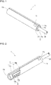
- FIG. 1 is a perspective view of the heat exchanger according to the present embodiment.
- FIG. 2 is a perspective view of the heat exchanger according to the present embodiment as viewed from a viewpoint different from FIG. 1 .
- FIG. 3 is a cross-sectional view of the heat exchanger according to the present embodiment.
- FIG. 4 is a development view of a ceramic body in the heat exchanger according to the present embodiment.
- FIG. 5 is an enlarged cross-sectional view of a main part of the heat exchanger according to the present embodiment.
- FIG. 6 is an enlarged cross-sectional view of a main part of a heat exchanger according to a modification of the present embodiment.
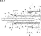
- FIG. 7 is an enlarged cross-sectional view of a main part of a heat exchanger according to another modification of the present embodiment.
- FIGs. 1 and 2 show a heater and a water receiver in the heat exchanger without showing other parts of the heat exchanger.
- FIGs. 3 and 5 to 7 schematically show the heat exchanger. The positions of a feedthrough conductor and an electrode pad shown in FIGs. 3 and 5 to 7 may be imprecise.
- a heat element and lead-out conductors are hatched.
- FIG. 4 is a development view of a surface of a surface layer facing a core.
- FIG. 5 is an enlarged cross-sectional view of area A shown in FIG. 3 . Enlarged cross-sectional views shown in FIGs. 6 and 7 each correspond to the enlarged cross-sectional view of the main part shown in FIG. 5 .
- a heat exchanger 1 includes a heater 10 and a water receiver 20.
- the heater 10 includes a ceramic body 11 and a heat element 12.
- the ceramic body 11 is tubular and has an open first end 11a and an open second end 11b.
- the ceramic body 11 may be a triangular tube, a rectangular tube, a cylinder, or an oval tube, or may have another shape. As shown in, for example, FIGs. 1 and 2 , the ceramic body 11 in the heat exchanger 1 is cylindrical.
- the ceramic body 11 is formed from an insulating ceramic material.
- the insulating ceramic material for the ceramic body 11 include alumina, silicon nitride, and aluminum nitride.
- Alumina may be used for its oxidation resistance and ease of manufacture.
- Silicon nitride may be used for its high strength, high toughness, high insulating performance, and high heat resistance.
- Aluminum nitride may be used for its high thermal conductivity.
- At least either an inner peripheral surface 11c or an outer peripheral surface 11d of the ceramic body 11 may be coated with a coating layer formed from a metal material.
- the coating improves the corrosion resistance of the ceramic body 11, thus improving the durability of the heat exchanger 1.
- the metal material for the coating layer include silver, gold, copper, and nickel.
- An oxide film may be on the outer surface of the coating layer.
- the ceramic body 11 includes a core 11e and a surface layer 11f.
- the core 11e is a cylinder having open ends.
- the surface layer 11f is located on the outer peripheral surface of the core 11e.
- the surface layer 11f may entirely or partially cover the outer peripheral surface of the core 11e.
- the core 11e has both ends in the axial direction of the ceramic body 11 (hereafter simply referred to as the axial direction) exposed from the surface layer 11f.
- the core 11e has, for example, an entire length in the axial direction of 30 to 150 mm, an outer diameter of 10 to 20 mm, and an inner diameter of 8 to 18 mm.
- the surface layer 11f has, for example, an entire length in the axial direction of 28 to 148 mm and a thickness of 0.2 to 1 mm.
- the ceramic body 11 may have, on the outer peripheral surface 11d, a recess 11g extending in the axial direction. As shown in, for example, FIGs. 1 and 2 , the recess 11g may be defined by the surface layer 11f partially covering the outer peripheral surface of the core 11e and the exposed portion of the outer peripheral surface of the core 11e. The recess 11g may extend entirely or partially across the length of the surface layer 11f in the axial direction.
- the heat element 12 is conductive and linear or strip-shaped.
- the heat element 12 generates heat upon receiving a current and heats a heating fluid with the ceramic body 11 in between.
- the heat element 12 is embedded in the ceramic body 11 and extends between the first end 11a and the second end 11b. As shown in, for example, FIGs. 2 , 3 , and 5 to 7 , the heat element 12 in the heat exchanger 1 is between the core 11e and the surface layer 11f.
- the heat element 12 may not be located on the exposed portions of the outer peripheral surface of the core 11e.
- the heat element 12 is formed from a conductive material mainly containing a metal having a high melting point.
- the conductive material for the heat element 12 mainly contains, for example, tungsten, molybdenum, or rhenium.
- the heat element 12 may contain the material for the ceramic body 11.
- the dimensions of the heat element 12 are determined as appropriate depending on, for example, the heating temperature of the heat element 12 and a voltage applied to the heat element 12.
- the heat element 12 may have, for example, a width of 0.3 to 2 mm, a thickness of 0.01 to 0.1 mm, and an entire length of 500 to 5000 mm.
- the ceramic body 11 may contain a compound containing a metallic element contained in the heat element 12.
- the ceramic body 11 may contain tungsten silicide (WSi 2 ) or molybdenum disilicide (MoSi 2 ).
- the heat element 12 may have a conductive pattern in which the heat element 12 is turned repeatedly between the first end 11a and the second end 11b of the ceramic body 11.
- the heat element 12 in the heat exchanger 1 has a conductive pattern in which the heat element 12 is turned repeatedly between the first end 11a and the second end 11b in the peripheral direction of the ceramic body 11.
- the heat element 12 has a meandering conductive pattern having multiple linear portions 12a and multiple turns 12b.
- the linear portions 12a extend in the axial direction and are parallel to one another with an interval.
- the turns 12b extend in the peripheral direction of the ceramic body 11 as viewed in a cross section perpendicular to the axial direction. Each turn 12b connects ends of adjacent linear portions 12a.
- the turns 12b may be linear as shown in, for example, FIGs. 2 and 4 or curved.
- the cross section of the heat element 12 may be circular, oval, rectangular, or in another shape.
- the heater 10 further includes lead-out conductors 13, feedthrough conductors 14, and electrode pads 15.
- the heat element 12 is electrically connected to an external circuit (external power source) with the lead-out conductors 13, the feedthrough conductors 14, and the electrode pads 15.
- Each lead-out conductor 13 is a linear or strip member. As shown in, for example, FIGs. 3 and 5 to 7 , the lead-out conductors 13 are between the core 11e and the surface layer 11f and extend in the axial direction. Each lead-out conductor 13 has a first end connected to the heat element 12 and a second end located nearer the first end 11a of the ceramic body 11 than the first end connected to the heat element 12.
- the lead-out conductors 13 are formed from, for example, a conductive material mainly containing a metal having a high melting point.
- the conductive material for the lead-out conductors 13 mainly contains, for example, tungsten, molybdenum, or rhenium.
- the lead-out conductors 13 may contain the material for the ceramic body 11.
- the lead-out conductors 13 may have a lower resistance value per unit length than the heat element 12.
- the lead-out conductors 13 may contain a lower amount of the material for the ceramic body 11 than the heat element 12 to have a lower resistance value per unit length than the heat element 12.
- the lead-out conductors 13 may have a larger cross-section area than the heat element 12 to have a lower resistance value per unit length than the heat element 12.
- the feedthrough conductors 14 are inside the ceramic body 11 and extend in the radial direction of the ceramic body 11.
- the feedthrough conductors 14 in the heat exchanger 1 extend through the surface layer 11f in the ceramic body 11.
- Each feedthrough conductor 14 has a first end face connected to the second end of the corresponding lead-out conductor 13 not connected to the heat element 12, and a second end face exposed on the outer peripheral surface 11d of the ceramic body 11.
- the feedthrough conductors 14 are formed from, for example, a conductive material mainly containing a metal having a high melting point.
- the conductive material for the feedthrough conductors 14 mainly contains, for example, tungsten, molybdenum, or rhenium.
- the feedthrough conductors 14 may contain the material for the ceramic body 11.
- the electrode pads 15 are located on the outer peripheral surface 11d of the ceramic body 11. Each electrode pad 15 covers an end face of the corresponding feedthrough conductor 14 exposed on the outer peripheral surface 11d. Each electrode pad 15 is joined with a lead terminal to electrically connect to an external circuit (external power source) through the lead terminal.
- the electrode pads 15 are formed from a conductive material containing, for example, tungsten or molybdenum. A plating layer formed from, for example, a nickel-boron alloy or gold may be on the outer surfaces of the electrode pads 15.
- the electrode pads 15 each have, for example, a thickness of 10 to 300 ⁇ m and a length and a width of 1 to 10 mm.
- the water receiver 20 is a cylinder having open ends.
- the water receiver 20 draws a heating fluid, for example, water from an external source into the ceramic body 11.
- the ceramic body 11 has an internal space defined by the inner peripheral surface 11c of the ceramic body 11.
- the water receiver 20 has one end (hereafter also referred to as the first end) 20a placed inside the ceramic body 11 and fixed to the heater 10.
- the water receiver 20 may be fixed to the heater 10 with an adhesive between an outer peripheral surface 20b of the water receiver 20 at the first end 20a and the inner peripheral surface 11c of the ceramic body 11, or with another method.
- the water receiver 20 has a second end, opposite to the first end 20a, connected to an external source of a heating fluid.
- the water receiver 20 may have the outer peripheral surface 20b at the first end 20a along the entire periphery in contact with the inner peripheral surface 11c of the ceramic body 11.
- the first end 20a may have an end face inclined with respect to the axial direction of the ceramic body 11, as shown in, for example, FIGs. 3 and 5 .
- the first end 20a may have an end face orthogonal to the axis of the ceramic body 11, as shown in, for example, FIGs. 6 and 7 .
- the water receiver 20 is formed from, for example, a resin material or a metal material.
- the resin material for the water receiver 20 include a fluororesin and a silicone resin.
- the metal material for the water receiver 20 include stainless steel.
- the water receiver 20 has, for example, an outer diameter of 8 to 18 mm and an inner diameter of 3 to 13 mm. The length of the water receiver 20 is determined as appropriate depending on the distance between the heater 10 and the external source of a heating fluid.
- the heat exchanger 1 includes a heat exchange channel through which a heating fluid flows.
- the heat exchange channel includes a first channel F1 defined by the inner peripheral surface of the water receiver 20 and a second channel F2 defined by the inner peripheral surface 11c of the ceramic body 11 and having a larger cross-sectional area than the first channel F1.
- the second channel F2 is downstream from the first channel F1 in the flow direction of a heating fluid (from left to right in FIGs. 3 and 5 to 7 ).
- streamlines of the heating fluid in the second channel F2 in a part adjacent to the first channel F1 (upstream part of the second channel F2) leave the inner peripheral surface 11c, allowing turbulence of the heating fluid to be more likely to occur.
- the heat exchanger 1 thus enables efficient heat exchange between the heating fluid and the heater 10.
- the first end 20a is at least partially located nearer the second end 11b of the ceramic body 11 than an end of the heat element 12 nearer the first end 11a of the ceramic body 11.
- the first end 20a is at least partially placed in a part inside the ceramic body 11 that reaches high temperatures due to the embedded heat element 12 during operation.
- the upstream part of the second channel F2 in which turbulence is likely to occur thus includes a part that reaches high temperatures during operation.
- the heat exchanger 1 thus enables efficient heat exchange using turbulence in a part of the heat exchange channel that reaches high temperatures.
- the heat exchanger 1 heats the heating fluid efficiently with lower power consumption.
- the entire periphery of the first end 20a of the water receiver 20 may be located nearer the second end 11b of the ceramic body 11 than an end of the heat element 12 nearer the first end 11a of the ceramic body 11.
- This structure causes turbulence in a part of the ceramic body 11 that reaches high temperatures during operation and thus enables efficient heat exchange in the part, enabling more efficient heating of the heating fluid.
- the heat exchanger 1 having the structure shown in FIG. 6 further reduces power consumption.
- the first end 20a of the water receiver 20 may have an inner diameter increasing toward the second end 11b of the ceramic body 11.
- This structure reduces the decrease in the flow velocity of the heating fluid caused by, for example, a pressure drop in the first channel F1.
- This structure effectively causes turbulence in a part of the ceramic body 11 that reaches high temperatures during operation and enables efficient heat exchange in the part, thus enabling more efficient heating of the heating fluid.
- the heat exchanger 1 having the structure shown in FIG. 7 further reduces power consumption.
- the heat exchanger 1 further includes a flange 30.
- the flange 30 facilitates attachment of the heater 10 to an external device.
- the flange 30 is annular and has a hole 30a to receive the ceramic body 11 as shown in, for example, FIGs. 3 and 5 to 7 .
- the flange 30 is formed from, for example, a metal material. Examples of the metal material for the flange 30 include stainless steel and an iron-nickel-cobalt alloy. Stainless steel may be used for its high corrosion resistance.
- the surface of the flange 30 may be coated with a plating layer mainly containing a metal such as nickel, tin, or gold to improve the corrosion resistance of the flange 30.
- the flange 30 is fixed to the heater 10 with an inner peripheral surface 30aa of its hole 30a joined to the outer peripheral surface 11d of the ceramic body 11.
- the inner peripheral surface 30aa may be joined to the outer peripheral surface 11d of the ceramic body 11 with a metal layer 34 in between.
- the metal layer 34 is located nearer the second end 11b of the ceramic body 11 than the electrode pads 15 in the axial direction. Examples of the metal material for the metal layer 34 include tungsten and molybdenum.
- the flange 30 may be joined to the outer surface of the metal layer 34 with a bond 35.
- the bond 35 may be any appropriate material that joins the flange 30 to the metal layer 34.
- the bond 35 may be, for example, a brazing material such as a silver brazing material and a silver-copper brazing material.
- a plating layer formed from, for example, nickel, tin, or gold may be on the outer surface of the metal layer 34. This improves the wettability of the metal layer 34 with the bond 35, thus increasing the bonding strength between the ceramic body 11 and the flange 30.
- the first end 20a of the water receiver 20 is at least partially located nearer the second end 11b than an edge 30ab of the inner peripheral surface 30aa of the hole 30a nearer the first end 11a.
- the first end 20a overlaps the inner peripheral surface 30aa as viewed in a direction perpendicular to the axial direction.
- the heat exchanger with this structure is durable and enables efficient heating of a heating fluid over a long period.
- the heat element 12 meandering as shown in, for example, FIG. 4 has turns 12b that reach the highest temperature in the heat element 12 at ends 12c of the heat element 12 nearer the first end 11a.
- the heat exchanger 1 reduces deterioration of the water receiver 20 under heat generated by the heat element 12.
- the heat exchanger 1 is durable and enables efficient heating of a heating fluid over a long period.
- the flange 30 may have a first portion 31, a second portion 32, and a third portion 33.
- the first portion 31 stands upright and radially outward from the metal layer 34.
- the second portion 32 extends from the outer peripheral edge of the first portion 31 toward the first end 11a of the ceramic body 11.
- the third portion 33 extends radially outward from an end of the second portion 32 nearer the first end 11a.
- the flange 30 has two bends between its inner periphery and outer periphery as viewed in a cross section including the axis of the ceramic body 11.
- the metal layer 34 may have a length in the axial direction greater than the length of the inner peripheral surface 30aa in the axial direction. This structure allows the bond 35 to form a meniscus extending from the metal layer 34 to the first portion 31 in the flange 30, thus increasing the bonding strength between the heater 10 and the flange 30 and improving the durability of the heat exchanger 1.
- the heat exchanger 1 further includes a connection member 40 and an annular member 50.
- the connection member 40 is tubular and has open ends.
- the connection member 40 continuously covers the outer peripheral surface of a portion of the ceramic body 11 adjacent to the first end 11a and an outer peripheral surface 20c of a portion of the water receiver 20 exposed from the ceramic body 11.
- the connection member 40 may include multiple cylindrical members with different sizes connected coaxially with each other.
- the inner peripheral surface of the connection member 40 may be in contact with the outer peripheral surface 11d of the ceramic body 11 and the outer peripheral surface 20c of the water receiver 20.
- connection member 40 is formed from, for example, a metal material or a resin material.
- metal material for the connection member 40 include stainless steel and an iron-nickel-cobalt alloy.
- resin material for the connection member 40 include a fluororesin and a silicone resin.
- connection member 40 at the connection between the heater 10 and the water receiver 20 improves the durability of the mechanical connection between the heater 10 and the water receiver 20.
- the heat exchanger with this structure is durable.
- the annular member 50 is an annular member (O-ring) including a resin material.
- the annular member 50 is between the inner peripheral surface of the connection member 40 and the outer peripheral surface 11d of the ceramic body 11.
- the resin material for the annular member 50 include a fluororesin and a silicone resin.
- the annular member 50 between the ceramic body 11 and the connection member 40 reduces stress caused by the difference in thermal expansion between the ceramic body 11 and the connection member 40, thus reducing cracks in the ceramic body 11.
- the heat exchanger with this structure is durable.
- the annular member 50 may be in contact with a portion of the outer peripheral surface 11d of the ceramic body 11 with no heat element 12 embedded.
- This structure reduces deterioration of the annular member 50 under heat generated by the heat element 12.
- the heat exchanger with this structure is durable and enables efficient heating of a heating fluid.
- the heat exchanger 1 further includes a case 60.
- the case 60 is tubular and has a closed first end and an open second end.
- the case 60 may be a triangular tube, a rectangular tube, a cylinder, or an oval tube, or may have another shape.
- the case 60 in the heat exchanger 1 is cylindrical.
- the heater 10 and the case 60 may be arranged to have the ceramic body 11 and the case 60 being coaxial.
- the case 60 is formed from a highly heat-resistant resin material.
- the resin material for the case 60 include a fluororesin.
- the case 60 has, for example, an entire length in the axial direction of 40 to 160 mm and an inner diameter of 10 to 25 mm.
- the case 60 has an opening 60a at the open second end in which the heater 10 is held. As shown in FIGs. 3 and 5 to 7 , the case 60 accommodates a portion of the ceramic body 11 nearer the first end 11a. As shown in FIGs. 3 and 5 to 7 , the heater 10 may be held in the case 60 with the second portion 32 of the flange 30 press-fitted in the opening 60a. The second portion 32 may be press-fitted in the opening 60a with an annular member (O-ring) formed from a resin material in between.
- O-ring annular member
- the first channel F1, the second channel F2, and a third channel F3 defined by the outer peripheral surface 11d of the ceramic body 11, an inner surface 60b of the case 60, and a surface of the flange 30 exposed inside the case 60 are connected to each other to define a channel for the heating fluid to pass through.
- the heating fluid exchanges heat with the heater 10 in the second channel F2 and the third channel F3.
- the case 60 includes an outlet 61 that allows the third channel F3 to be open outside.
- the outlet 61 allows ejection of the heating fluid heated by the heater 10.
- the outlet 61 has, for example, an inner diameter of 1 to 5 mm. As shown in, for example, FIGs.
- the outlet 61 may be at a position in the side wall of the case 60 nearer the first end 11a of the ceramic body 11. This structure facilitates heat exchange between the heating fluid and the heater 10 in the third channel F3, thus enabling efficient heating of the heating fluid.
- the ceramic body 11 is formed from alumina ceramic.
- an alumina ceramic green sheet to be the surface layer 11f of the ceramic body 11 is prepared with alumina (Al 2 O 3 ) as a main component and silica (SiO 2 ), calcium oxide (CaO), magnesia (MgO), and zirconia (ZrO 2 ) in a combined total amount less than or equal to 10% by mass.
- Predetermined patterns to be the heat element 12 and the lead-out conductors 13 are formed on the alumina ceramic green sheet.
- the predetermined patterns are formed by, for example, screen printing, a transfer process, or embedding a resistor.
- the predetermined patterns may be formed by, for example, etching a metal leaf or shaping nichrome wire into a coil and embedding the wire. Screen printing may be used for stable quality and lower manufacturing costs.
- the heat element 12 and the lead-out conductors 13 may be formed with different methods.
- predetermined patterns to be the electrode pads 15 and the metal layer 34 are formed on the surface opposite to the surface of the ceramic green sheet on which the heat element 12 and the lead-out conductors 13 are formed, in the same manner as with the heat element 12 and the lead-out conductors 13. Holes for forming the feedthrough conductors 14 that electrically connect the lead-out conductors 13 and the electrode pads 15 are punched in the ceramic green sheet and filled with a conductive paste to be the feedthrough conductors 14.
- a conductive paste mainly containing a metal having a high melting point such as tungsten, molybdenum, and rhenium may be used for the heat element 12, the lead-out conductors 13, the feedthrough conductors 14, and the electrode pads 15.
- a cylindrical alumina ceramic molded body to be the core 11e in the ceramic body 11 is formed by extrusion molding.
- the cylindrical alumina ceramic molded body is wrapped in the alumina ceramic green sheet described above.
- An adhesion liquid containing an alumina ceramic material having the same composition as the green sheet in a dispersed manner is then applied and stuck tightly to the molded body to obtain an integrally molded alumina body to be the ceramic body 11.
- the alumina ceramic green sheet may be wrapped around the alumina ceramic molded body with a predetermined area on the outer peripheral surface of the alumina ceramic molded body left uncovered with the alumina ceramic green sheet to obtain an integrally molded alumina body including a groove to be the recess 11g.
- the integrally molded alumina body is fired in a reducing atmosphere (nitrogen atmosphere) at 1500 to 1600 °C and thus shrinks to form a sintered integral alumina body (ceramic body 11).
- the electrode pads 15 and the metal layer 34 on the ceramic body 11 are plated.
- the plating typically uses, for example, nickel, gold, or tin.
- a plating technique may be selected from, for example, electroless plating, electroplating, and barrel plating, in accordance with use.
- the flange 30 may be manufactured from a stainless-steel plate, which undergoes processes such as cutting, punching, and pressing to have a shape including the first portion 31, the second portion 32, and the third portion 33, as well as the hole 30a to receive the ceramic body 11.
- the ceramic body 11 is set on a fixture.
- the flange 30 is then positioned to have the hole 30a aligned with the metal layer 34 on the outer peripheral surface 11d of the ceramic body 11.
- the ceramic body 11 is then brazed using the bond 35 at about 1000 °C in a furnace with a reducing atmosphere.
- annular member formed from, for example, rubber is attached to the outer peripheral surface of the second portion 32 in the flange 30.
- the case 60 formed from a resin is prepared.
- the case 60 receives and holds the heater 10 with the annular member attached.
- the water receiver 20 formed from, for example, a resin material or a metal material is then placed inside the ceramic body 11.
- the heat exchanger 1 may be thus manufactured.
- the washing apparatus includes the heat exchanger 1 described above.
- the washing apparatus heats, with the heater 10, water drawn from an external water source through the water receiver 20 and ejects the heated water outside.
- the external water source may be, for example, a public water supply system.
- the water flows from the first channel F1 into the second channel F2 and then into the third channel F3, and is ejected through the outlet 61. While passing through the second channel F2 and the third channel F3, the water is heated by the heater 10 to a predetermined temperature.
- the heated water may be used for, for example, washing a part of a human body.
- the washing apparatus according to the present embodiment including the heat exchanger 1 heats water efficiently with lower power consumption.
- a heat exchanger includes a heater including a ceramic body being tubular and having a first end being open and a second end being open and a heat element embedded in the ceramic body, and a water receiver being tubular and having a first end being open and a second end being open.
- the first end of the water receiver is through the first end of the ceramic body and is located inside the ceramic body.
- the first end of the water receiver is at least partially nearer the second end of the ceramic body than an end of the heat element nearer the first end of the ceramic body.
- the heat exchanger according to the above aspect of the present disclosure heats a heating fluid efficiently with lower power consumption.
- a washing apparatus according to one aspect of the present disclosure includes the heat exchanger described above. The washing apparatus heats water efficiently with lower power consumption.
Landscapes
- Physics & Mathematics (AREA)
- Engineering & Computer Science (AREA)
- Fluid Mechanics (AREA)
- Thermal Sciences (AREA)
- Chemical & Material Sciences (AREA)
- Combustion & Propulsion (AREA)
- Mechanical Engineering (AREA)
- General Engineering & Computer Science (AREA)
- Instantaneous Water Boilers, Portable Hot-Water Supply Apparatuses, And Control Of Portable Hot-Water Supply Apparatuses (AREA)
- Resistance Heating (AREA)
- Bidet-Like Cleaning Device And Other Flush Toilet Accessories (AREA)
Abstract
Description
- The present disclosure relates to a heat exchanger for, for example, a fluid heating apparatus, a gas heating apparatus, a powder heating apparatus, an oxygen sensor, and a soldering iron, and to a washing apparatus including the heat exchanger.
- A known technique is described in, for example,
Patent Literature 1. - Patent Literature 1:
Japanese Unexamined Patent Application Publication No. 60-10033 - A heat exchanger according to one aspect of the present disclosure includes a heater including a ceramic body being tubular and having a first end being open and a second end being open and a heat element embedded in the ceramic body, and a water receiver being tubular and having a first end being open and a second end being open. The first end of the water receiver is through the first end of the ceramic body and is located inside the ceramic body. The first end of the water receiver is at least partially nearer the second end of the ceramic body than an end of the heat element nearer the first end of the ceramic body.
- A washing apparatus according to one aspect of the present disclosure includes the heat exchanger described above. The washing apparatus heats, with the heater, water drawn from an external water source through the water receiver and ejects the water.
- The objects, features, and advantages of the present disclosure will become more apparent from the following detailed description and the drawings.
-
FIG. 1 is a perspective view of a heat exchanger according to an embodiment. -
FIG. 2 is a perspective view of the heat exchanger according to the embodiment as viewed from a viewpoint different fromFIG. 1 . -
FIG. 3 is a cross-sectional view of the heat exchanger according to the embodiment. -
FIG. 4 is a development view of a ceramic body in the heat exchanger according to the embodiment. -
FIG. 5 is an enlarged cross-sectional view of a main part of the heat exchanger according to the embodiment. -
FIG. 6 is an enlarged cross-sectional view of a main part of a heat exchanger according to a modification of the embodiment. -
FIG. 7 is an enlarged cross-sectional view of a main part of a heat exchanger according to another modification of the embodiment. - A known heat exchanger with the structure that forms the basis of a heat exchanger according to one or more embodiments of the present disclosure may be included in a washing apparatus and include a hollow cylindrical heater including an internal water channel, and a water feeding line for feeding water into the water channel.
- The heat exchanger is to efficiently heat a heating fluid. In a heat exchanger with the structure that forms the basis of the heat exchanger according to one or more embodiments of the present disclosure, water flowing through the water channel in the heater is likely to be laminar. This may reduce the efficiency of heat exchange between the water and the heater, possibly causing inefficient heating of the water.
- The heat exchanger according to an embodiment of the present disclosure will now be described with reference to the drawings.
-
FIG. 1 is a perspective view of the heat exchanger according to the present embodiment.FIG. 2 is a perspective view of the heat exchanger according to the present embodiment as viewed from a viewpoint different fromFIG. 1 .FIG. 3 is a cross-sectional view of the heat exchanger according to the present embodiment.FIG. 4 is a development view of a ceramic body in the heat exchanger according to the present embodiment.FIG. 5 is an enlarged cross-sectional view of a main part of the heat exchanger according to the present embodiment.FIG. 6 is an enlarged cross-sectional view of a main part of a heat exchanger according to a modification of the present embodiment.FIG. 7 is an enlarged cross-sectional view of a main part of a heat exchanger according to another modification of the present embodiment.FIGs. 1 and 2 show a heater and a water receiver in the heat exchanger without showing other parts of the heat exchanger.FIGs. 3 and5 to 7 schematically show the heat exchanger. The positions of a feedthrough conductor and an electrode pad shown inFIGs. 3 and5 to 7 may be imprecise. InFIGs. 2 and4 , a heat element and lead-out conductors are hatched.FIG. 4 is a development view of a surface of a surface layer facing a core.FIG. 5 . is an enlarged cross-sectional view of area A shown inFIG. 3 . Enlarged cross-sectional views shown inFIGs. 6 and7 each correspond to the enlarged cross-sectional view of the main part shown inFIG. 5 . - A
heat exchanger 1 includes aheater 10 and awater receiver 20. Theheater 10 includes aceramic body 11 and aheat element 12. - The
ceramic body 11 is tubular and has an openfirst end 11a and an opensecond end 11b. Theceramic body 11 may be a triangular tube, a rectangular tube, a cylinder, or an oval tube, or may have another shape. As shown in, for example,FIGs. 1 and 2 , theceramic body 11 in theheat exchanger 1 is cylindrical. - The
ceramic body 11 is formed from an insulating ceramic material. Examples of the insulating ceramic material for theceramic body 11 include alumina, silicon nitride, and aluminum nitride. Alumina may be used for its oxidation resistance and ease of manufacture. Silicon nitride may be used for its high strength, high toughness, high insulating performance, and high heat resistance. Aluminum nitride may be used for its high thermal conductivity. - At least either an inner
peripheral surface 11c or an outerperipheral surface 11d of theceramic body 11 may be coated with a coating layer formed from a metal material. The coating improves the corrosion resistance of theceramic body 11, thus improving the durability of theheat exchanger 1. Examples of the metal material for the coating layer include silver, gold, copper, and nickel. An oxide film may be on the outer surface of the coating layer. - As shown in, for example,
FIGs. 1 to 3 and5 to 7 , theceramic body 11 includes acore 11e and asurface layer 11f. Thecore 11e is a cylinder having open ends. Thesurface layer 11f is located on the outer peripheral surface of thecore 11e. Thesurface layer 11f may entirely or partially cover the outer peripheral surface of thecore 11e. In theheat exchanger 1, thecore 11e has both ends in the axial direction of the ceramic body 11 (hereafter simply referred to as the axial direction) exposed from thesurface layer 11f. Thecore 11e has, for example, an entire length in the axial direction of 30 to 150 mm, an outer diameter of 10 to 20 mm, and an inner diameter of 8 to 18 mm. Thesurface layer 11f has, for example, an entire length in the axial direction of 28 to 148 mm and a thickness of 0.2 to 1 mm. - The
ceramic body 11 may have, on the outerperipheral surface 11d, arecess 11g extending in the axial direction. As shown in, for example,FIGs. 1 and 2 , therecess 11g may be defined by thesurface layer 11f partially covering the outer peripheral surface of thecore 11e and the exposed portion of the outer peripheral surface of thecore 11e. Therecess 11g may extend entirely or partially across the length of thesurface layer 11f in the axial direction. - The
heat element 12 is conductive and linear or strip-shaped. Theheat element 12 generates heat upon receiving a current and heats a heating fluid with theceramic body 11 in between. Theheat element 12 is embedded in theceramic body 11 and extends between thefirst end 11a and thesecond end 11b. As shown in, for example,FIGs. 2 ,3 , and5 to 7 , theheat element 12 in theheat exchanger 1 is between the core 11e and thesurface layer 11f. Theheat element 12 may not be located on the exposed portions of the outer peripheral surface of thecore 11e. - The
heat element 12 is formed from a conductive material mainly containing a metal having a high melting point. The conductive material for theheat element 12 mainly contains, for example, tungsten, molybdenum, or rhenium. Theheat element 12 may contain the material for theceramic body 11. The dimensions of theheat element 12 are determined as appropriate depending on, for example, the heating temperature of theheat element 12 and a voltage applied to theheat element 12. Theheat element 12 may have, for example, a width of 0.3 to 2 mm, a thickness of 0.01 to 0.1 mm, and an entire length of 500 to 5000 mm. Theceramic body 11 may contain a compound containing a metallic element contained in theheat element 12. For example, when theheat element 12 contains tungsten or molybdenum, theceramic body 11 may contain tungsten silicide (WSi2) or molybdenum disilicide (MoSi2). - The
heat element 12 may have a conductive pattern in which theheat element 12 is turned repeatedly between thefirst end 11a and thesecond end 11b of theceramic body 11. As shown in, for example,FIGs. 2 and4 , theheat element 12 in theheat exchanger 1 has a conductive pattern in which theheat element 12 is turned repeatedly between thefirst end 11a and thesecond end 11b in the peripheral direction of theceramic body 11. In other words, theheat element 12 has a meandering conductive pattern having multiplelinear portions 12a andmultiple turns 12b. Thelinear portions 12a extend in the axial direction and are parallel to one another with an interval. The turns 12b extend in the peripheral direction of theceramic body 11 as viewed in a cross section perpendicular to the axial direction. Eachturn 12b connects ends of adjacentlinear portions 12a. Theturns 12b may be linear as shown in, for example,FIGs. 2 and4 or curved. The cross section of theheat element 12 may be circular, oval, rectangular, or in another shape. - The
heater 10 further includes lead-outconductors 13,feedthrough conductors 14, andelectrode pads 15. Theheat element 12 is electrically connected to an external circuit (external power source) with the lead-outconductors 13, thefeedthrough conductors 14, and theelectrode pads 15. - Each lead-
out conductor 13 is a linear or strip member. As shown in, for example,FIGs. 3 and5 to 7 , the lead-outconductors 13 are between the core 11e and thesurface layer 11f and extend in the axial direction. Each lead-out conductor 13 has a first end connected to theheat element 12 and a second end located nearer thefirst end 11a of theceramic body 11 than the first end connected to theheat element 12. - The lead-out
conductors 13 are formed from, for example, a conductive material mainly containing a metal having a high melting point. The conductive material for the lead-outconductors 13 mainly contains, for example, tungsten, molybdenum, or rhenium. The lead-outconductors 13 may contain the material for theceramic body 11. - The lead-out
conductors 13 may have a lower resistance value per unit length than theheat element 12. The lead-outconductors 13 may contain a lower amount of the material for theceramic body 11 than theheat element 12 to have a lower resistance value per unit length than theheat element 12. In some embodiments, the lead-outconductors 13 may have a larger cross-section area than theheat element 12 to have a lower resistance value per unit length than theheat element 12. - The
feedthrough conductors 14 are inside theceramic body 11 and extend in the radial direction of theceramic body 11. Thefeedthrough conductors 14 in theheat exchanger 1 extend through thesurface layer 11f in theceramic body 11. Eachfeedthrough conductor 14 has a first end face connected to the second end of the corresponding lead-out conductor 13 not connected to theheat element 12, and a second end face exposed on the outerperipheral surface 11d of theceramic body 11. - The
feedthrough conductors 14 are formed from, for example, a conductive material mainly containing a metal having a high melting point. The conductive material for thefeedthrough conductors 14 mainly contains, for example, tungsten, molybdenum, or rhenium. Thefeedthrough conductors 14 may contain the material for theceramic body 11. - The
electrode pads 15 are located on the outerperipheral surface 11d of theceramic body 11. Eachelectrode pad 15 covers an end face of the correspondingfeedthrough conductor 14 exposed on the outerperipheral surface 11d. Eachelectrode pad 15 is joined with a lead terminal to electrically connect to an external circuit (external power source) through the lead terminal. Theelectrode pads 15 are formed from a conductive material containing, for example, tungsten or molybdenum. A plating layer formed from, for example, a nickel-boron alloy or gold may be on the outer surfaces of theelectrode pads 15. Theelectrode pads 15 each have, for example, a thickness of 10 to 300 µm and a length and a width of 1 to 10 mm. - The
water receiver 20 is a cylinder having open ends. Thewater receiver 20 draws a heating fluid, for example, water from an external source into theceramic body 11. Theceramic body 11 has an internal space defined by the innerperipheral surface 11c of theceramic body 11. Thewater receiver 20 has one end (hereafter also referred to as the first end) 20a placed inside theceramic body 11 and fixed to theheater 10. Thewater receiver 20 may be fixed to theheater 10 with an adhesive between an outerperipheral surface 20b of thewater receiver 20 at thefirst end 20a and the innerperipheral surface 11c of theceramic body 11, or with another method. Thewater receiver 20 has a second end, opposite to thefirst end 20a, connected to an external source of a heating fluid. - The
water receiver 20 may have the outerperipheral surface 20b at thefirst end 20a along the entire periphery in contact with the innerperipheral surface 11c of theceramic body 11. Thefirst end 20a may have an end face inclined with respect to the axial direction of theceramic body 11, as shown in, for example,FIGs. 3 and5 . Thefirst end 20a may have an end face orthogonal to the axis of theceramic body 11, as shown in, for example,FIGs. 6 and7 . - The
water receiver 20 is formed from, for example, a resin material or a metal material. Examples of the resin material for thewater receiver 20 include a fluororesin and a silicone resin. Examples of the metal material for thewater receiver 20 include stainless steel. Thewater receiver 20 has, for example, an outer diameter of 8 to 18 mm and an inner diameter of 3 to 13 mm. The length of thewater receiver 20 is determined as appropriate depending on the distance between theheater 10 and the external source of a heating fluid. - The
heat exchanger 1 includes a heat exchange channel through which a heating fluid flows. The heat exchange channel includes a first channel F1 defined by the inner peripheral surface of thewater receiver 20 and a second channel F2 defined by the innerperipheral surface 11c of theceramic body 11 and having a larger cross-sectional area than the first channel F1. The second channel F2 is downstream from the first channel F1 in the flow direction of a heating fluid (from left to right inFIGs. 3 and5 to 7 ). During the operation of theheat exchanger 1, streamlines of the heating fluid in the second channel F2 in a part adjacent to the first channel F1 (upstream part of the second channel F2) leave the innerperipheral surface 11c, allowing turbulence of the heating fluid to be more likely to occur. With turbulence, a part of the heating fluid after exchanging heat with the innerperipheral surface 11c flows apart from the innerperipheral surface 11c, and another part of the heating fluid yet to exchange heat with the innerperipheral surface 11c flows nearer the innerperipheral surface 11c. Thus, the heat distribution of the heating fluid is more likely to be uniform in the radial direction of theceramic body 11. Theheat exchanger 1 thus enables efficient heat exchange between the heating fluid and theheater 10. - In the
heat exchanger 1, thefirst end 20a is at least partially located nearer thesecond end 11b of theceramic body 11 than an end of theheat element 12 nearer thefirst end 11a of theceramic body 11. In other words, as shown in, for example,FIGs. 3 and5 , thefirst end 20a is at least partially placed in a part inside theceramic body 11 that reaches high temperatures due to the embeddedheat element 12 during operation. The upstream part of the second channel F2 in which turbulence is likely to occur thus includes a part that reaches high temperatures during operation. Theheat exchanger 1 thus enables efficient heat exchange using turbulence in a part of the heat exchange channel that reaches high temperatures. Theheat exchanger 1 heats the heating fluid efficiently with lower power consumption. - As shown in
FIG. 6 , the entire periphery of thefirst end 20a of thewater receiver 20 may be located nearer thesecond end 11b of theceramic body 11 than an end of theheat element 12 nearer thefirst end 11a of theceramic body 11. This structure causes turbulence in a part of theceramic body 11 that reaches high temperatures during operation and thus enables efficient heat exchange in the part, enabling more efficient heating of the heating fluid. Thus, theheat exchanger 1 having the structure shown inFIG. 6 further reduces power consumption. - As shown in
FIG. 7 , thefirst end 20a of thewater receiver 20 may have an inner diameter increasing toward thesecond end 11b of theceramic body 11. This structure reduces the decrease in the flow velocity of the heating fluid caused by, for example, a pressure drop in the first channel F1. This allows the heating fluid flowing from the first channel F1 into the second channel F2 to maintain a flow velocity for effective generation of turbulence in the upstream part in the second channel F2. This structure effectively causes turbulence in a part of theceramic body 11 that reaches high temperatures during operation and enables efficient heat exchange in the part, thus enabling more efficient heating of the heating fluid. Theheat exchanger 1 having the structure shown inFIG. 7 further reduces power consumption. - The
heat exchanger 1 further includes aflange 30. Theflange 30 facilitates attachment of theheater 10 to an external device. Theflange 30 is annular and has ahole 30a to receive theceramic body 11 as shown in, for example,FIGs. 3 and5 to 7 . Theflange 30 is formed from, for example, a metal material. Examples of the metal material for theflange 30 include stainless steel and an iron-nickel-cobalt alloy. Stainless steel may be used for its high corrosion resistance. The surface of theflange 30 may be coated with a plating layer mainly containing a metal such as nickel, tin, or gold to improve the corrosion resistance of theflange 30. - The
flange 30 is fixed to theheater 10 with an inner peripheral surface 30aa of itshole 30a joined to the outerperipheral surface 11d of theceramic body 11. As shown in, for example,FIGs. 3 and5 to 7 , the inner peripheral surface 30aa may be joined to the outerperipheral surface 11d of theceramic body 11 with ametal layer 34 in between. Themetal layer 34 is located nearer thesecond end 11b of theceramic body 11 than theelectrode pads 15 in the axial direction. Examples of the metal material for themetal layer 34 include tungsten and molybdenum. - The
flange 30 may be joined to the outer surface of themetal layer 34 with abond 35. Thebond 35 may be any appropriate material that joins theflange 30 to themetal layer 34. Thebond 35 may be, for example, a brazing material such as a silver brazing material and a silver-copper brazing material. A plating layer formed from, for example, nickel, tin, or gold may be on the outer surface of themetal layer 34. This improves the wettability of themetal layer 34 with thebond 35, thus increasing the bonding strength between theceramic body 11 and theflange 30. - In the
heat exchanger 1, as shown in, for example,FIGs. 3 and5 to 7 , thefirst end 20a of thewater receiver 20 is at least partially located nearer thesecond end 11b than an edge 30ab of the inner peripheral surface 30aa of thehole 30a nearer thefirst end 11a. In other words, thefirst end 20a overlaps the inner peripheral surface 30aa as viewed in a direction perpendicular to the axial direction. This structure allows heat dissipation from theflange 30 to reduce the likelihood of the temperature of thefirst end 20a increasing excessively under heat generated by theheat element 12. With thewater receiver 20 formed from a resin material as well, this structure reduces deformation and deterioration of thefirst end 20a under heat generated by theheat element 12, allowing reliable generation of turbulence in the second channel F2. Thus, the heat exchanger with this structure is durable and enables efficient heating of a heating fluid over a long period. More specifically, theheat element 12 meandering as shown in, for example,FIG. 4 , has turns 12b that reach the highest temperature in theheat element 12 atends 12c of theheat element 12 nearer thefirst end 11a. With this structure as well, theheat exchanger 1 reduces deterioration of thewater receiver 20 under heat generated by theheat element 12. Thus, theheat exchanger 1 is durable and enables efficient heating of a heating fluid over a long period. - As shown in, for example,
FIGs. 3 and5 to 7 , theflange 30 may have afirst portion 31, asecond portion 32, and athird portion 33. Thefirst portion 31 stands upright and radially outward from themetal layer 34. Thesecond portion 32 extends from the outer peripheral edge of thefirst portion 31 toward thefirst end 11a of theceramic body 11. Thethird portion 33 extends radially outward from an end of thesecond portion 32 nearer thefirst end 11a. In other words, as shown in, for example,FIGs. 3 and5 to 7 , theflange 30 has two bends between its inner periphery and outer periphery as viewed in a cross section including the axis of theceramic body 11. - As shown in, for example,
FIGs. 3 and5 to 7 , themetal layer 34 may have a length in the axial direction greater than the length of the inner peripheral surface 30aa in the axial direction. This structure allows thebond 35 to form a meniscus extending from themetal layer 34 to thefirst portion 31 in theflange 30, thus increasing the bonding strength between theheater 10 and theflange 30 and improving the durability of theheat exchanger 1. - The
heat exchanger 1 further includes aconnection member 40 and anannular member 50. Theconnection member 40 is tubular and has open ends. Theconnection member 40 continuously covers the outer peripheral surface of a portion of theceramic body 11 adjacent to thefirst end 11a and an outerperipheral surface 20c of a portion of thewater receiver 20 exposed from theceramic body 11. As shown in, for example,FIGs. 3 and5 to 7 , theconnection member 40 may include multiple cylindrical members with different sizes connected coaxially with each other. The inner peripheral surface of theconnection member 40 may be in contact with the outerperipheral surface 11d of theceramic body 11 and the outerperipheral surface 20c of thewater receiver 20. - The
connection member 40 is formed from, for example, a metal material or a resin material. Examples of the metal material for theconnection member 40 include stainless steel and an iron-nickel-cobalt alloy. Examples of the resin material for theconnection member 40 include a fluororesin and a silicone resin. - The
connection member 40 at the connection between theheater 10 and thewater receiver 20 improves the durability of the mechanical connection between theheater 10 and thewater receiver 20. The heat exchanger with this structure is durable. - The
annular member 50 is an annular member (O-ring) including a resin material. Theannular member 50 is between the inner peripheral surface of theconnection member 40 and the outerperipheral surface 11d of theceramic body 11. Examples of the resin material for theannular member 50 include a fluororesin and a silicone resin. - The
annular member 50 between theceramic body 11 and theconnection member 40 reduces stress caused by the difference in thermal expansion between theceramic body 11 and theconnection member 40, thus reducing cracks in theceramic body 11. The heat exchanger with this structure is durable. - As shown in, for example,
FIGs. 3 and5 to 7 , theannular member 50 may be in contact with a portion of the outerperipheral surface 11d of theceramic body 11 with noheat element 12 embedded. This structure reduces deterioration of theannular member 50 under heat generated by theheat element 12. The heat exchanger with this structure is durable and enables efficient heating of a heating fluid. - The
heat exchanger 1 further includes acase 60. Thecase 60 is tubular and has a closed first end and an open second end. Thecase 60 may be a triangular tube, a rectangular tube, a cylinder, or an oval tube, or may have another shape. Thecase 60 in theheat exchanger 1 is cylindrical. Theheater 10 and thecase 60 may be arranged to have theceramic body 11 and thecase 60 being coaxial. - The
case 60 is formed from a highly heat-resistant resin material. Examples of the resin material for thecase 60 include a fluororesin. Thecase 60 has, for example, an entire length in the axial direction of 40 to 160 mm and an inner diameter of 10 to 25 mm. - The
case 60 has anopening 60a at the open second end in which theheater 10 is held. As shown inFIGs. 3 and5 to 7 , thecase 60 accommodates a portion of theceramic body 11 nearer thefirst end 11a. As shown inFIGs. 3 and5 to 7 , theheater 10 may be held in thecase 60 with thesecond portion 32 of theflange 30 press-fitted in theopening 60a. Thesecond portion 32 may be press-fitted in theopening 60a with an annular member (O-ring) formed from a resin material in between. - In the
heat exchanger 1, the first channel F1, the second channel F2, and a third channel F3 defined by the outerperipheral surface 11d of theceramic body 11, aninner surface 60b of thecase 60, and a surface of theflange 30 exposed inside thecase 60 are connected to each other to define a channel for the heating fluid to pass through. The heating fluid exchanges heat with theheater 10 in the second channel F2 and the third channel F3. As shown in, for example,FIGs. 3 and5 to 7 , thecase 60 includes anoutlet 61 that allows the third channel F3 to be open outside. Theoutlet 61 allows ejection of the heating fluid heated by theheater 10. Theoutlet 61 has, for example, an inner diameter of 1 to 5 mm. As shown in, for example,FIGs. 3 and5 to 7 , theoutlet 61 may be at a position in the side wall of thecase 60 nearer thefirst end 11a of theceramic body 11. This structure facilitates heat exchange between the heating fluid and theheater 10 in the third channel F3, thus enabling efficient heating of the heating fluid. - An example method for manufacturing the
heat exchanger 1 will now be described. In the example described below, theceramic body 11 is formed from alumina ceramic. - First, an alumina ceramic green sheet to be the
surface layer 11f of theceramic body 11 is prepared with alumina (Al2O3) as a main component and silica (SiO2), calcium oxide (CaO), magnesia (MgO), and zirconia (ZrO2) in a combined total amount less than or equal to 10% by mass. Predetermined patterns to be theheat element 12 and the lead-outconductors 13 are formed on the alumina ceramic green sheet. The predetermined patterns are formed by, for example, screen printing, a transfer process, or embedding a resistor. The predetermined patterns may be formed by, for example, etching a metal leaf or shaping nichrome wire into a coil and embedding the wire. Screen printing may be used for stable quality and lower manufacturing costs. Theheat element 12 and the lead-outconductors 13 may be formed with different methods. - Subsequently, predetermined patterns to be the
electrode pads 15 and themetal layer 34 are formed on the surface opposite to the surface of the ceramic green sheet on which theheat element 12 and the lead-outconductors 13 are formed, in the same manner as with theheat element 12 and the lead-outconductors 13. Holes for forming thefeedthrough conductors 14 that electrically connect the lead-outconductors 13 and theelectrode pads 15 are punched in the ceramic green sheet and filled with a conductive paste to be thefeedthrough conductors 14. A conductive paste mainly containing a metal having a high melting point such as tungsten, molybdenum, and rhenium may be used for theheat element 12, the lead-outconductors 13, thefeedthrough conductors 14, and theelectrode pads 15. - A cylindrical alumina ceramic molded body to be the core 11e in the
ceramic body 11 is formed by extrusion molding. The cylindrical alumina ceramic molded body is wrapped in the alumina ceramic green sheet described above. An adhesion liquid containing an alumina ceramic material having the same composition as the green sheet in a dispersed manner is then applied and stuck tightly to the molded body to obtain an integrally molded alumina body to be theceramic body 11. The alumina ceramic green sheet may be wrapped around the alumina ceramic molded body with a predetermined area on the outer peripheral surface of the alumina ceramic molded body left uncovered with the alumina ceramic green sheet to obtain an integrally molded alumina body including a groove to be therecess 11g. The integrally molded alumina body is fired in a reducing atmosphere (nitrogen atmosphere) at 1500 to 1600 °C and thus shrinks to form a sintered integral alumina body (ceramic body 11). - Subsequently, the
electrode pads 15 and themetal layer 34 on theceramic body 11 are plated. The plating typically uses, for example, nickel, gold, or tin. A plating technique may be selected from, for example, electroless plating, electroplating, and barrel plating, in accordance with use. - The
flange 30 may be manufactured from a stainless-steel plate, which undergoes processes such as cutting, punching, and pressing to have a shape including thefirst portion 31, thesecond portion 32, and thethird portion 33, as well as thehole 30a to receive theceramic body 11. - Subsequently, the
ceramic body 11 is set on a fixture. Theflange 30 is then positioned to have thehole 30a aligned with themetal layer 34 on the outerperipheral surface 11d of theceramic body 11. Theceramic body 11 is then brazed using thebond 35 at about 1000 °C in a furnace with a reducing atmosphere. - Subsequently, an annular member (O-ring) formed from, for example, rubber is attached to the outer peripheral surface of the
second portion 32 in theflange 30. Thecase 60 formed from a resin is prepared. Thecase 60 receives and holds theheater 10 with the annular member attached. Thewater receiver 20 formed from, for example, a resin material or a metal material is then placed inside theceramic body 11. Theheat exchanger 1 may be thus manufactured. - A washing apparatus according to an embodiment of the present disclosure will now be described.
- The washing apparatus according to the present embodiment includes the
heat exchanger 1 described above. The washing apparatus heats, with theheater 10, water drawn from an external water source through thewater receiver 20 and ejects the heated water outside. The external water source may be, for example, a public water supply system. The water flows from the first channel F1 into the second channel F2 and then into the third channel F3, and is ejected through theoutlet 61. While passing through the second channel F2 and the third channel F3, the water is heated by theheater 10 to a predetermined temperature. The heated water may be used for, for example, washing a part of a human body. The washing apparatus according to the present embodiment including theheat exchanger 1 heats water efficiently with lower power consumption. - The present disclosure may be implemented in the following forms.
- A heat exchanger according to one aspect of the present disclosure includes a heater including a ceramic body being tubular and having a first end being open and a second end being open and a heat element embedded in the ceramic body, and a water receiver being tubular and having a first end being open and a second end being open. The first end of the water receiver is through the first end of the ceramic body and is located inside the ceramic body. The first end of the water receiver is at least partially nearer the second end of the ceramic body than an end of the heat element nearer the first end of the ceramic body.
- The heat exchanger according to the above aspect of the present disclosure heats a heating fluid efficiently with lower power consumption. A washing apparatus according to one aspect of the present disclosure includes the heat exchanger described above. The washing apparatus heats water efficiently with lower power consumption.
- Although the embodiments of the present disclosure have been described in detail, the present disclosure is not limited to the above embodiments, and may be modified or changed variously without departing from the spirit and scope of the present disclosure. The components described in the above embodiments may be entirely or partially combined as appropriate unless any contradiction arises.
-
- 1
- heat exchanger
- 10
- heater
- 11
- ceramic body
- 11a
- first end
- 11b
- second end
- 11c
- inner peripheral surface
- 11d
- outer peripheral surface
- 11e
- core
- 11f
- surface layer
- 11g
- recess
- 12
- heat element
- 12a
- linear portion
- 12b
- turn
- 12c
- end
- 13
- lead-out conductor
- 14
- feedthrough conductor
- 15
- electrode pad
- 20
- water receiver
- 20a
- one end (first end)
- 20b
- outer peripheral surface
- 20c
- outer peripheral surface
- 30
- flange
- 30a
- hole
- 30aa
- inner peripheral surface
- 30ab
- edge
- 31
- first portion
- 32
- second portion
- 33
- third portion
- 34
- metal layer
- 35
- bond
- 40
- connection member
- 50
- annular member
- 60
- case
- 60a
- opening
- 60b
- inner surface
- 61
- outlet
Claims (7)
- A heat exchanger, comprising:a heater including a ceramic body and a heat element embedded in the ceramic body, the ceramic body being tubular and having a first end being open and a second end being open; anda water receiver being tubular and having a first end being open and a second end being open, the first end of the water receiver being through the first end of the ceramic body and located inside the ceramic body, the first end of the water receiver being at least partially nearer the second end of the ceramic body than an end of the heat element nearer the first end of the ceramic body.
- The heat exchanger according to claim 1, wherein
the first end of the water receiver includes an entire periphery located nearer the second end of the ceramic body than the end of the heat element nearer the first end of the ceramic body. - The heat exchanger according to claim 1 or claim 2, further comprising:a flange having a hole receiving the ceramic body, the hole having an inner peripheral surface joined to an outer peripheral surface of the ceramic body,wherein the water receiver comprises a resin material, and has the first end at least partially located nearer the second end of the ceramic body than an edge of the inner peripheral surface nearer the first end of the ceramic body.
- The heat exchanger according to any one of claims 1 to 3, wherein
the heat element has a meandering shape including a plurality of linear portions extending in an axial direction of the ceramic body and a plurality of turns extending in a peripheral direction of the ceramic body. - The heat exchanger according to any one of claims 1 to 4, further comprising:a tubular connection member continuously covering an outer peripheral surface of a portion of the ceramic body adjacent to the first end of the ceramic body and an outer peripheral surface of a portion of the water receiver exposed from the ceramic body; andan annular member comprising a resin material and located between an inner peripheral surface of the connection member and an outer peripheral surface of the ceramic body.
- The heat exchanger according to any one of claims 1 to 5, wherein
the first end of the water receiver has an inner diameter increasing toward the second end of the ceramic body. - A washing apparatus, comprising:the heat exchanger according to any one of claims 1 to 6,wherein the washing apparatus is configured to heat, with the heater, water drawn from an external water source through the water receiver and eject the water.
Applications Claiming Priority (2)
| Application Number | Priority Date | Filing Date | Title |
|---|---|---|---|
| JP2019036108 | 2019-02-28 | ||
| PCT/JP2020/007792 WO2020175564A1 (en) | 2019-02-28 | 2020-02-26 | Heat exchange unit and cleaning device provided with same |
Publications (2)
| Publication Number | Publication Date |
|---|---|
| EP3934378A1 true EP3934378A1 (en) | 2022-01-05 |
| EP3934378A4 EP3934378A4 (en) | 2022-11-23 |
Family
ID=72239012
Family Applications (1)
| Application Number | Title | Priority Date | Filing Date |
|---|---|---|---|
| EP20762958.5A Pending EP3934378A4 (en) | 2019-02-28 | 2020-02-26 | Heat exchange unit and cleaning device provided with same |
Country Status (5)
| Country | Link |
|---|---|
| US (1) | US12235018B2 (en) |
| EP (1) | EP3934378A4 (en) |
| JP (1) | JPWO2020175564A1 (en) |
| CN (1) | CN113455103B (en) |
| WO (1) | WO2020175564A1 (en) |
Family Cites Families (19)
| Publication number | Priority date | Publication date | Assignee | Title |
|---|---|---|---|---|
| JPS589046Y2 (en) | 1978-04-07 | 1983-02-18 | 株式会社コロナ | Vaporizer for oil burning appliances |
| JPS6010033A (en) | 1983-06-27 | 1985-01-19 | 東陶機器株式会社 | Puvic washing apparatus |
| US7875832B2 (en) * | 2004-12-20 | 2011-01-25 | Ngk Spark Plug Co., Ltd. | Ceramic heater, heat exchange unit, and warm water washing toilet seat |
| US7221860B2 (en) * | 2005-04-22 | 2007-05-22 | Momentive Performance Materials Inc. | Vacuum insulated heater assembly |
| KR100880773B1 (en) * | 2008-01-23 | 2009-02-02 | (주) 씨엠테크 | Fluid heater |
| JP5724506B2 (en) | 2010-03-31 | 2015-05-27 | Toto株式会社 | Heat exchanger and sanitary washing apparatus provided with the same |
| EP2407069A1 (en) * | 2010-07-12 | 2012-01-18 | Bleckmann GmbH & Co. KG | Dynamic flow-through heater |
| JP5766348B2 (en) | 2012-03-29 | 2015-08-19 | 京セラ株式会社 | Tubular heater |
| JP6062821B2 (en) * | 2013-07-31 | 2017-01-18 | 京セラ株式会社 | heater |
| US9341391B2 (en) * | 2013-12-31 | 2016-05-17 | Bollente Companies, Inc. | Automatically controlled flow-through water heater system |
| JP6194025B2 (en) * | 2014-01-30 | 2017-09-06 | 京セラ株式会社 | heater |
| KR101468724B1 (en) | 2014-04-29 | 2014-12-08 | 임진수 | Electric heating boiler system at the moment |
| WO2016068207A1 (en) * | 2014-10-30 | 2016-05-06 | 京セラ株式会社 | Heater and fluid heating device using same |
| US11096250B2 (en) * | 2014-10-31 | 2021-08-17 | Ngk Spark Plug Co., Ltd. | Ceramic heater and manufacturing method for same |
| DE102015119863B4 (en) * | 2015-11-17 | 2024-11-21 | Borgwarner Ludwigsburg Gmbh | Electric heating device for heating fluids |
| ES2914290T3 (en) * | 2016-07-05 | 2022-06-08 | Ngk Spark Plug Co | ceramic heater |
| JP2018084380A (en) | 2016-11-24 | 2018-05-31 | アイシン精機株式会社 | Heating device and local part cleaning device including the same |
| JP6856668B2 (en) * | 2017-01-18 | 2021-04-07 | 京セラ株式会社 | Heater device |
| JP6835946B2 (en) | 2017-02-24 | 2021-02-24 | 京セラ株式会社 | heater |
-
2020
- 2020-02-26 US US17/433,373 patent/US12235018B2/en active Active
- 2020-02-26 WO PCT/JP2020/007792 patent/WO2020175564A1/en not_active Ceased
- 2020-02-26 EP EP20762958.5A patent/EP3934378A4/en active Pending
- 2020-02-26 CN CN202080015805.7A patent/CN113455103B/en active Active
- 2020-02-26 JP JP2021502326A patent/JPWO2020175564A1/en active Pending
Also Published As
| Publication number | Publication date |
|---|---|
| US20220170665A1 (en) | 2022-06-02 |
| EP3934378A4 (en) | 2022-11-23 |
| JPWO2020175564A1 (en) | 2021-12-16 |
| CN113455103B (en) | 2024-11-22 |
| US12235018B2 (en) | 2025-02-25 |
| CN113455103A (en) | 2021-09-28 |
| WO2020175564A1 (en) | 2020-09-03 |
Similar Documents
| Publication | Publication Date | Title |
|---|---|---|
| JP7525569B2 (en) | Heat exchange unit and cleaning device equipped with same | |
| JP3801756B2 (en) | Ceramic glow plug | |
| TW200812422A (en) | Heating element for a hot air device | |
| CN108476558B (en) | Heating device | |
| JP5766348B2 (en) | Tubular heater | |
| JP6856668B2 (en) | Heater device | |
| US12235018B2 (en) | Heat exchanger and washing apparatus including heat exchanger | |
| JP7444946B2 (en) | heater | |
| CN110521279B (en) | Heating device | |
| JP2017182910A (en) | heater | |
| JP6798812B2 (en) | heater | |
| JP2018018671A (en) | heater | |
| JPWO2018096778A1 (en) | heater | |
| JP6940443B2 (en) | heater | |
| JP6835946B2 (en) | heater | |
| JP6532779B2 (en) | Ceramic heater and sensor | |
| CN221769347U (en) | A heating component and an aerosol generating device | |
| JP6711708B2 (en) | heater | |
| CN117356763A (en) | A heating component and aerosol generating device | |
| WO2022244624A1 (en) | Ceramic heater and liquid heating device | |
| WO2022244623A1 (en) | Liquid heating device | |
| CN118355730A (en) | Heater | |
| JP2534548B2 (en) | Hot runner probe using ceramic heater with lead wire | |
| JP2017212173A (en) | heater |
Legal Events
| Date | Code | Title | Description |
|---|---|---|---|
| STAA | Information on the status of an ep patent application or granted ep patent |
Free format text: STATUS: THE INTERNATIONAL PUBLICATION HAS BEEN MADE |
|
| PUAI | Public reference made under article 153(3) epc to a published international application that has entered the european phase |
Free format text: ORIGINAL CODE: 0009012 |
|
| STAA | Information on the status of an ep patent application or granted ep patent |
Free format text: STATUS: REQUEST FOR EXAMINATION WAS MADE |
|
| 17P | Request for examination filed |
Effective date: 20210819 |
|
| AK | Designated contracting states |
Kind code of ref document: A1 Designated state(s): AL AT BE BG CH CY CZ DE DK EE ES FI FR GB GR HR HU IE IS IT LI LT LU LV MC MK MT NL NO PL PT RO RS SE SI SK SM TR |
|
| DAV | Request for validation of the european patent (deleted) | ||
| DAX | Request for extension of the european patent (deleted) | ||
| A4 | Supplementary search report drawn up and despatched |
Effective date: 20221025 |
|
| RIC1 | Information provided on ipc code assigned before grant |
Ipc: F24H 9/13 20220101ALI20221019BHEP Ipc: F24H 1/10 20220101ALI20221019BHEP Ipc: H05B 3/48 20060101ALI20221019BHEP Ipc: H05B 3/18 20060101ALI20221019BHEP Ipc: H05B 3/40 20060101AFI20221019BHEP |
|
| P01 | Opt-out of the competence of the unified patent court (upc) registered |
Effective date: 20230505 |
|
| STAA | Information on the status of an ep patent application or granted ep patent |
Free format text: STATUS: EXAMINATION IS IN PROGRESS |
|
| 17Q | First examination report despatched |
Effective date: 20250829 |