EP3934316A1 - Communication device and communication method of same, information processing device and control method of same, and program - Google Patents
Communication device and communication method of same, information processing device and control method of same, and program Download PDFInfo
- Publication number
- EP3934316A1 EP3934316A1 EP20762282.0A EP20762282A EP3934316A1 EP 3934316 A1 EP3934316 A1 EP 3934316A1 EP 20762282 A EP20762282 A EP 20762282A EP 3934316 A1 EP3934316 A1 EP 3934316A1
- Authority
- EP
- European Patent Office
- Prior art keywords
- eht
- field
- sig
- radio frame
- legacy
- Prior art date
- Legal status (The legal status is an assumption and is not a legal conclusion. Google has not performed a legal analysis and makes no representation as to the accuracy of the status listed.)
- Pending
Links
Images


Classifications
-
- H—ELECTRICITY
- H04—ELECTRIC COMMUNICATION TECHNIQUE
- H04L—TRANSMISSION OF DIGITAL INFORMATION, e.g. TELEGRAPHIC COMMUNICATION
- H04L25/00—Baseband systems
- H04L25/02—Details ; arrangements for supplying electrical power along data transmission lines
- H04L25/03—Shaping networks in transmitter or receiver, e.g. adaptive shaping networks
- H04L25/03006—Arrangements for removing intersymbol interference
-
- H—ELECTRICITY
- H04—ELECTRIC COMMUNICATION TECHNIQUE
- H04W—WIRELESS COMMUNICATION NETWORKS
- H04W28/00—Network traffic management; Network resource management
- H04W28/02—Traffic management, e.g. flow control or congestion control
- H04W28/06—Optimizing the usage of the radio link, e.g. header compression, information sizing, discarding information
-
- H—ELECTRICITY
- H04—ELECTRIC COMMUNICATION TECHNIQUE
- H04L—TRANSMISSION OF DIGITAL INFORMATION, e.g. TELEGRAPHIC COMMUNICATION
- H04L27/00—Modulated-carrier systems
- H04L27/26—Systems using multi-frequency codes
- H04L27/2601—Multicarrier modulation systems
- H04L27/2602—Signal structure
-
- H—ELECTRICITY
- H04—ELECTRIC COMMUNICATION TECHNIQUE
- H04L—TRANSMISSION OF DIGITAL INFORMATION, e.g. TELEGRAPHIC COMMUNICATION
- H04L27/00—Modulated-carrier systems
- H04L27/26—Systems using multi-frequency codes
- H04L27/2601—Multicarrier modulation systems
- H04L27/2602—Signal structure
- H04L27/2603—Signal structure ensuring backward compatibility with legacy system
-
- H—ELECTRICITY
- H04—ELECTRIC COMMUNICATION TECHNIQUE
- H04L—TRANSMISSION OF DIGITAL INFORMATION, e.g. TELEGRAPHIC COMMUNICATION
- H04L27/00—Modulated-carrier systems
- H04L27/26—Systems using multi-frequency codes
- H04L27/2601—Multicarrier modulation systems
- H04L27/2647—Arrangements specific to the receiver only
- H04L27/2655—Synchronisation arrangements
- H04L27/2666—Acquisition of further OFDM parameters, e.g. bandwidth, subcarrier spacing, or guard interval length
-
- H—ELECTRICITY
- H04—ELECTRIC COMMUNICATION TECHNIQUE
- H04L—TRANSMISSION OF DIGITAL INFORMATION, e.g. TELEGRAPHIC COMMUNICATION
- H04L5/00—Arrangements affording multiple use of the transmission path
- H04L5/003—Arrangements for allocating sub-channels of the transmission path
- H04L5/0048—Allocation of pilot signals, i.e. of signals known to the receiver
-
- H—ELECTRICITY
- H04—ELECTRIC COMMUNICATION TECHNIQUE
- H04L—TRANSMISSION OF DIGITAL INFORMATION, e.g. TELEGRAPHIC COMMUNICATION
- H04L5/00—Arrangements affording multiple use of the transmission path
- H04L5/003—Arrangements for allocating sub-channels of the transmission path
- H04L5/0053—Allocation of signalling, i.e. of overhead other than pilot signals
-
- H—ELECTRICITY
- H04—ELECTRIC COMMUNICATION TECHNIQUE
- H04L—TRANSMISSION OF DIGITAL INFORMATION, e.g. TELEGRAPHIC COMMUNICATION
- H04L69/00—Network arrangements, protocols or services independent of the application payload and not provided for in the other groups of this subclass
- H04L69/30—Definitions, standards or architectural aspects of layered protocol stacks
- H04L69/32—Architecture of open systems interconnection [OSI] 7-layer type protocol stacks, e.g. the interfaces between the data link level and the physical level
- H04L69/322—Intralayer communication protocols among peer entities or protocol data unit [PDU] definitions
-
- H—ELECTRICITY
- H04—ELECTRIC COMMUNICATION TECHNIQUE
- H04W—WIRELESS COMMUNICATION NETWORKS
- H04W84/00—Network topologies
- H04W84/02—Hierarchically pre-organised networks, e.g. paging networks, cellular networks, WLAN [Wireless Local Area Network] or WLL [Wireless Local Loop]
- H04W84/10—Small scale networks; Flat hierarchical networks
- H04W84/12—WLAN [Wireless Local Area Networks]
-
- H—ELECTRICITY
- H04—ELECTRIC COMMUNICATION TECHNIQUE
- H04L—TRANSMISSION OF DIGITAL INFORMATION, e.g. TELEGRAPHIC COMMUNICATION
- H04L25/00—Baseband systems
- H04L25/02—Details ; arrangements for supplying electrical power along data transmission lines
- H04L25/03—Shaping networks in transmitter or receiver, e.g. adaptive shaping networks
- H04L25/03006—Arrangements for removing intersymbol interference
- H04L2025/03777—Arrangements for removing intersymbol interference characterised by the signalling
- H04L2025/03802—Signalling on the reverse channel
- H04L2025/03815—Transmission of a training request
-
- H—ELECTRICITY
- H04—ELECTRIC COMMUNICATION TECHNIQUE
- H04L—TRANSMISSION OF DIGITAL INFORMATION, e.g. TELEGRAPHIC COMMUNICATION
- H04L5/00—Arrangements affording multiple use of the transmission path
- H04L5/0001—Arrangements for dividing the transmission path
- H04L5/0003—Two-dimensional division
- H04L5/0005—Time-frequency
- H04L5/0007—Time-frequency the frequencies being orthogonal, e.g. OFDM(A) or DMT
-
- H—ELECTRICITY
- H04—ELECTRIC COMMUNICATION TECHNIQUE
- H04W—WIRELESS COMMUNICATION NETWORKS
- H04W52/00—Power management, e.g. Transmission Power Control [TPC] or power classes
- H04W52/02—Power saving arrangements
- H04W52/0209—Power saving arrangements in terminal devices
- H04W52/0225—Power saving arrangements in terminal devices using monitoring of external events, e.g. the presence of a signal
-
- Y—GENERAL TAGGING OF NEW TECHNOLOGICAL DEVELOPMENTS; GENERAL TAGGING OF CROSS-SECTIONAL TECHNOLOGIES SPANNING OVER SEVERAL SECTIONS OF THE IPC; TECHNICAL SUBJECTS COVERED BY FORMER USPC CROSS-REFERENCE ART COLLECTIONS [XRACs] AND DIGESTS
- Y02—TECHNOLOGIES OR APPLICATIONS FOR MITIGATION OR ADAPTATION AGAINST CLIMATE CHANGE
- Y02D—CLIMATE CHANGE MITIGATION TECHNOLOGIES IN INFORMATION AND COMMUNICATION TECHNOLOGIES [ICT], I.E. INFORMATION AND COMMUNICATION TECHNOLOGIES AIMING AT THE REDUCTION OF THEIR OWN ENERGY USE
- Y02D30/00—Reducing energy consumption in communication networks
- Y02D30/70—Reducing energy consumption in communication networks in wireless communication networks
Definitions
- the present invention relates to a communication device, a communication method thereof, an information processing device, a control method thereof, and a program and, more particularly, to a communication control technique in a wireless LAN.
- IEEE802.11EHT Extremely High Throughput
- PTL 1 Japanese Patent Laid-Open No. 2018-050133
- the present invention provides a technique of preventing a communication device from unnecessarily continuing to read a radio frame upon receiving a radio frame complying with a standard to which the device is not adaptable.
- a communication device characterized by comprising communication means for transmitting or receiving a radio frame including a preamble and a data field of a physical layer (PHY), wherein the preamble includes an L-STF (Legacy Short Training Field), an L-LTF (Legacy Long Training Field), an L-SIG (Legacy Signal Field), an EHT-SIG-A (Extremely High Throughput Signal A Field), an EHT-STF (EHT Short Training Field), and an EHT-LTF (EHT Long Training Field), and the EHT-SIG-A includes a field indicating a standard that the radio frame complies with.
- L-STF Legacy Short Training Field
- L-LTF Legacy Long Training Field
- L-SIG Legacy Signal Field
- EHT-SIG-A Extremely High Throughput Signal A Field
- EHT-STF EHT Short Training Field
- EHT-LTF EHT Long Training Field
- Fig. 1 shows an example of the configuration of a wireless communication network according to this embodiment.
- This wireless communication network includes one access point (AP) and three stations (STAs).
- AP access point
- STAs stations
- each of an AP 102 and an STA 103 complies with IEEE802.11EHT (Extremely High Throughput), and is configured to be capable of performing wireless communication complying with standards defined before the IEEE802.11EHT standard.
- An STA 104 is an STA that is adaptable to the IEEE802.11ax standard but not to IEEE802.11EHT.
- an STA 105 is an STA that is adaptable to communication standards after the IEEE802.11EHT.
- the access point may be referred to as "AP” and the station (terminal) may be referred to as "STA” without reference numerals.
- AP access point
- STA station
- the wireless communication network including one AP and three STAs is shown as an example, but the numbers of these communication devices may be more or less than shown.
- no AP may exist when the STAs communicate with each other.
- Fig. 1 the wireless communication network including one AP and three STAs is shown as an example, but the numbers of these communication devices may be more or less than shown.
- no AP may exist when the STAs communicate with each other.
- the communicable area of the network formed by the AP 102 is indicated by a circle 101. Note that this communicable area may cover a larger area, or may cover only a smaller area. Note that it may be understood that EHT is an acronym of Extreme High Throughput.
- Fig. 2 shows an example of the hardware configuration of each of the communication devices (the AP and the STAs).
- the communication device includes, as an example of its hardware configuration, a storage unit 201, a control unit 202, a function unit 203, an input unit 204, an output unit 205, a communication unit 206, and an antenna 207.
- the storage unit 201 is formed by both of a ROM and a RAM or one of them, and stores programs for performing various kinds of operations to be described later and various kinds of information such as communication parameters for wireless communication.
- a storage medium such as a flexible disk, a hard disk, an optical disk, a magnetooptical disk, a CD-ROM, a CD-R, a magnetic tape, a nonvolatile memory card, or a DVD may be used as the storage unit 201.
- the control unit 202 is formed by, for example, one or more processors such as a CPU and an MPU, an ASIC (Application Specific Integrated Circuit), a DSP (Digital Signal Processor), an FPGA (Field Programmable Gate Array), or the like.
- CPU is an acronym of Central Processing Unit
- MPU is an acronym of Micro Processing Unit.
- the control unit 202 executes the programs stored in the storage unit 201, thereby controlling the entire device. Note that the control unit 202 may control the entire device by cooperation of the programs stored in the storage unit 201 and an OS (Operating System).
- control unit 202 controls the function unit 203 to execute predetermined processing such as image capturing, printing, or projection.
- the function unit 203 is hardware used by the device to execute predetermined processing. For example, if the device is a camera, the function unit 203 is an image capturing unit and performs image capturing processing. For example, if the device is a printer, the function unit 203 is a printing unit and performs print processing. For example, if the device is a projector, the function unit 203 is a projection unit and performs projection processing.
- Data to be processed by the function unit 203 may be data stored in the storage unit 201, or may be data communicated with another AP or STA via the communication unit 206 to be described later.
- the input unit 204 accepts various kinds of operations from a user.
- the output unit 205 performs various kinds of outputs for the user.
- the output by the output unit 205 includes, for example, at least one of display on a screen, audio output by a loudspeaker, vibration output, and the like.
- both the input unit 204 and the output unit 205 may be implemented by one module, like a touch panel.
- the communication unit 206 controls wireless communication complying with the IEEE802.11 standard series, or controls IP communication.
- the communication unit 206 is a so-called radio chip, and may itself include one or more processors and memories. In this embodiment, the communication unit 206 can execute processing complying with at least the IEEE802.11ax standard.
- the communication unit 206 controls the antenna 207 to transmit and receive radio signals for wireless communication.
- the device communicates contents such as image data, document data, or video data with another communication device via the communication unit 206.
- the antenna 207 is an antenna that can transmit and receive signals in at least any one of, for example, a sub-GHz band, 2.4 GHz band, 5 GHz band, and 6 GHz band.
- the frequency band (and a combination of frequency bands) to which the antenna 207 is adaptable is not particularly limited.
- the antenna 207 may be one antenna, or may be a set of two or more antennas to perform MIMO (Multi-Input and Multi-Output) transmission/reception.
- Fig. 2 shows one antenna 207, but the antenna may include two or more antennas (two or more sets of antennas) that are adaptable to different frequency bands.
- Fig. 3 shows an example of the functional configuration of each of the communication devices (the AP and the STAs).
- the communication device includes a wireless LAN control unit 301, a frame analysis unit 302, a frame generation unit 303, a UI control unit 304, a storage unit 305, and an antenna 306.
- the wireless LAN control unit 301 is configured to include circuits that transmit/receive radio signals to/from another wireless LAN device (for example, another AP or STA) using the antenna 306, and programs configured to control these.
- the wireless LAN control unit 301 executes communication control of wireless LAN such as transmission of a frame generated by the frame generation unit 303 and reception of a radio frame from another wireless LAN device in accordance with the IEEE802.11 standard series.
- the frame analysis unit 302 analyzes a radio frame received via the wireless LAN control unit 301. This analysis is done by reading the radio frame from the head.
- the frame analysis unit 302 analyzes the physical layer (PHY) preamble of a radio frame, as will be described later, thereby operating to discard a radio frame for a standard (version) the communication device does not comply with. Since this allows the communication device to early interrupt analysis of a radio frame of a type the self-device does not comply with, the power consumption can be reduced.
- the frame generation unit 303 generates, for example, a radio frame including data to be transmitted to another AP or STA.
- the self-device complies with or, in some cases, a standard the partner device of communication complies with, the frame generation unit 303 generates a radio frame complying with a standard that enables communication between the self-device and the partner device.
- the UI control unit 304 is configured to include hardware concerning user interfaces (UIs) such as a touch panel and buttons configured to accept an operation on the communication device by the user (not shown) of the communication device, and programs configured to control these. Note that the UI control unit 304 also has a function of, for example, presenting information to the user, such as display of an image or the like or audio output.
- the storage unit 305 is configured to include a storage device such as a ROM (Read Only Memory) or a RAM (Random Access Memory) configured to store programs to be executed by the communication device and various kinds of data.
- Fig. 4 shows an example of the procedure of processing to be executed by the communication devices (the AP and the STAs) according to this embodiment, which comply with IEEE802.11EHT.
- the communication device decides an operating frequency band (step S401).
- the decision of the operating frequency band is performed by the AP. That is, if the communication device is an AP, the operating frequency band is decided by a user operation of the communication device, or the like. If the communication device is an STA, it is decided that the STA operates in the operating frequency band decided by the AP of the connection destination.
- the operating frequency band can be one of frequency bands of, for example, 2.4 GHz, 5 GHz, and 6 GHz. If another usable frequency band exists, the frequency band may be used. Note that in the following description, a frequency band of 2.4 GHz or 5 GHz, which is usable by communication devices complying with old-generation communication standards, is used.
- the communication device decides a standard a radio frame should comply with when transmitting the radio frame.
- the communication device determines whether the standard is IEEE802.11EHT (step S402).
- the communication device decides the communication standard to be used based on, for example, the standard the self-device complies with and the standard the partner device complies with. For example, if both the communication device and the partner device comply with IEEE802.11EHT, the communication device decides to use the IEEE802.11EHT. If one of the communication device and the partner device complies with a successor standard of IEEE802.11EHT, and the other complies with IEEE802.11EHT but not with the successor standard, the communication device decides to use the IEEE802.11EHT.
- the communication device decides to use the old-generation standard. For example, in communication between the AP 102 and the STA 103, since both comply with IEEE802.11EHT, it is decided to use the IEEE802.11EHT. In communication between the AP 102 and the STA 104, since the AP 102 complies with IEEE802.11EHT, but the STA 104 complies with only IEEE802.11ax, it is decided to use the IEEE802.11ax.
- the STA 105 In communication between the AP 102 and the STA 105, since the STA 105 complies with a successor standard of IEEE802.11EHT, but the AP 102 do not comply with the successor standard, it is decided to use the IEEE802.11EHT.
- the "successor standard" here includes, for example, Wave2 of IEEE802.11EHT, and the like. That is, in this embodiment, different versions of IEEE802.11EHT, which are obtained by further improving, after formulation, the IEEE802.11EHT standard that uses radio frames to be discussed below, are also handled as successor standards.
- the communication device Upon deciding to use the IEEE802.11EHT (YES in step S402), the communication device sets a field (for example, a Version subfield to be described later) indicating the type of the standard in the radio frame and sets a value indicating EHT in the field (step S403). Note that upon deciding to use a standard after the IEEE802.11EHT, the communication device can prepare a field indicating the type of the standard and set a value indicating the standard to be used in the field. In this case, in step S402, the communication device determines whether to use a standard after IEEE802.11EHT. If a standard after IEEE802.11EHT is to be used, an appropriate value can be set in the field indicating the type of the standard.
- a field for example, a Version subfield to be described later
- the communication device generates a radio frame (PPDU) including such a field indicating the type of the standard.
- PPDU is an acronym of Physical Layer (PHY) Protocol Data Unit.
- the communication device upon deciding to use an old-generation standard (legacy standard) before IEEE802.11EHT (NO in step S402), the communication device generates a radio frame (PPDU) in accordance with the old-generation standard. Then, the communication device transmits the generated radio frame (step S404).
- radio frame transmission here also includes transmission of a beacon. That is, if the communication device is an AP, the communication device generates and transmits a beacon in accordance with the communication standard the self-device complies with. Note that if the self-device does not transmit a radio frame and only receives a radio frame from the partner device, the communication device may omit the processes of steps S402 to S404.
- the communication device receives a radio frame from the partner device (step S405).
- the partner device here indicates the partner device with which the communication device directly communicates wirelessly. For example, if the communication device is an STA, the partner device is the connected AP. If the communication device is an AP, the partner device is the STA connected to the self-device.
- the communication device determines whether the received radio frame is a radio frame of a legacy standard (step S406).
- the legacy standard indicates the IEEE802.11a/b/g/n/ax standards.
- the communication device reads the whole radio frame (step S407).
- the communication device upon determining that a radio frame of a standard after the IEEE802.11ax standard, that is, a standard after IEEE802.11EHT is received (NO in step S406), the communication device reads the field indicating the type of the standard as described above (step S408). The communication device then determines whether the self-device is adaptable to the standard of the type indicated by a value set in the read field (whether an operation complying with the standard is possible) (step S409). For example, a communication device complying with IEEE802.11EHT determines whether the value set in the field is a value corresponding to IEEE802.11EHT.
- the communication device continues the analysis of the radio frame and reads the whole radio frame (step S410).
- the communication device continues the analysis while handling data stored in the data field as a frame of a MAC (Medium Access Control) layer.
- the communication device does not analyze the radio frame anymore and discards the radio frame (step S411). This makes it possible to prevent the communication device from unnecessarily continuing to read the radio frame of the standard to which the device is not adaptable and prevent waste of the power consumption of the communication device.
- the communication device may perform only transmission of a radio frame, and if no radio frame is received, the processing from step S405 may be omitted.
- the AP generates a Beacon frame including information indicating the standard the self-device complies with and sends it.
- the STA transmits a Probe Request frame based on the Beacon frame.
- the AP determines whether the Probe Request frame is a legacy frame, and if the Probe Request frame is not a legacy frame, determines whether the Probe Request frame is generated in accordance with the standard the self-device complies with. If the Probe Request frame is a legacy frame or is generated in accordance with the standard the self-device complies with, the AP performs analysis in the MAC layer. The AP can recognize, by the analysis in the MAC layer, that the frame is a Probe Request frame, and transmit the Probe Response frame.
- the AP discards the frame. Note that since the frame is discarded without performing analysis in the MAC layer, the AP does not recognize that the frame is a Probe Request frame. For this reason, the AP does not transmit the Probe Response frame.
- the communication device may execute the signal transmission processing in steps S402 to S404 and the signal reception processing in steps S405 to S411 in different communication opportunities, or may execute these processes as a series of processes in one communication opportunity.
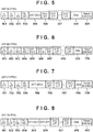
- Figs. 5 to 8 Examples of the structures of radio frames complying with IEEE802.11EHT are shown in Figs. 5 to 8.
- Fig. 5 shows an example of an EHT SU (Single User) PPDU that is a PPDU for single-user communication
- Fig. 6 shows an example of an EHT MU (Multi User) PPDU for multi-user communication
- Fig. 7 shows an example of an EHT ER (Extended Range) PPDU for long distance transmission
- Fig. 8 shows an example of an EHT TB (Trigger based) PPDU that is transmitted from the STA as a response to a trigger frame transmitted from the AP.
- the EHT ER PPDU is used when the communication area should be extended in communication between an AP and a single STA.
- the PPDU includes fields including an STF (Short Training Field), an LTF (Long Training Field), and a SIG (Signal Field).
- the head portion of the PPDU includes an L (Legacy)-STF 501, an L-LTF 502, and an L-SIG 503 for ensuring backward compatibility with the IEEE802.11a/b/g/n/ax standards.
- each of frame formats shown in Figs. 6 to 8 includes an L-STF (L-STF 601, 701, or 801), an L-LTF (L-LTF 602, 702, or 802), and an L-SIG (L-SIG 603, 703, or 803).
- each of the structures shown in Figs. 6 to 8 further includes an RL-SIG (Repeated L-SIG, an RL-SIG 504, 604, 704, or 804) arranged immediately after the L-SIG.
- the RL-SIG field the contents of the L-SIG are repeatedly transmitted.
- the RL-SIG is used to enable a receiver to recognize that this PPDU complies with a standard after the IEEE802.11ax standard, and may be omitted in IEEE802.11EHT in some cases.
- a field for enabling the receiver to recognize that this PPDU complies with the IEEE802.11EHT may be provided in place of the RL-SIG.
- the L-STF is used for detection of a PHY frame signal, AGC (Automatic Gain Control), timing detection, or the like.
- the L-LTF is used for highly accurate frequency/time synchronization, obtainment of propagation channel information (CSI: Channel State Information), or the like.
- the L-SIG is used for transmitting control information including information such as a data transmission rate and a PHY frame length.
- a legacy device complying with the IEEE802.11a/b/g/n/ax standards can decode the above-described various kinds of legacy fields.
- Each PPDU further includes an EHT-SIG (EHT-SIG-A 505, 605, 705, or 805 and EHT-SIG-B 606) arranged immediately after the RL-SIG and used for transmitting control information for EHT.
- Each PPDU further includes an STF for EHT (EHT-STF 506, 607, 706, or 806) and an LTF for EHT (EHT-LTF 507, 608, 707, or 807).
- Each PPDU includes, after these controlling fields, a data field 508, 609, 708, or 808 and a Packet extension field 509, 610, 709, or 809.
- the portion including the fields from the L-STF to the EHT-LTF of each PPDU is referred to as a PHY preamble.
- the respective fields of each PPDU may not necessarily be arranged in the order shown in each of Figs. 5 to 8 , or may include a new field not shown in each of Figs. 5 to 8 .
- each of Figs. 5 to 8 shows the PPDU that can ensure the backward compatibility as an example.
- the legacy fields may be omitted.
- the EHT-STF and EHT-LTF are used in place of the L-STF and the L-LTF to establish synchronization.
- the EHT-STF and one of the plurality of EHT-LTFs after the EHT-SIG field can be omitted.
- the EHT-SIG-A 505 and 705 included in the EHT SU PPDU and the EHT ER PPDU include an EHT-SIG-A1 and an EHT-SIG-A2 necessary for reception of the PPDU, respectively, as shown in Tables 1 and 2 below.
- the EHT-SIG-A 605 of the EHT MU PPDU shown in Fig. 6 includes an EHT-SIG-A1 and an EHT-SIG-A2 necessary for reception of the PPDU, as shown in Tables 3 and 4 below.
- EHT-SIG-A1 includes an EHT-SIG-A1 and an EHT-SIG-A2 necessary for reception of the PPDU, as shown in Tables 5 and 6 below.
- a "Version" subfield indicating which standard a radio frame is generated is included in 3 bits in the head of the EHT-SIG-A1.
- Bit Position Subfield Bit Count Description EHT-SIG-A1 B0-B2 Version 3 This subfield indicates a version of the frame. "0” is set if the frame is a EHT -frame.
- B3 Format 1 "1" is set for an EHT PPDU and an EHT ER PPDU to distinguish them from an EHT TB PPDU.
- B4 Beam Change 1 "1" is set if the pre-EHT of the PPDU is arranged in a space different from the first symbol of the EHT-LTF, or "0" is set if the pre-EHT is mapped similarly to the first symbol.
- B5 UL/DL 1 This subfield indicates whether the PPDU is for UL or DL, and has the same value as TXVECTOR UPLINK_FLAG.
- B10 DCM 1 This subfield indicates whether Dual Carrier Modulation is applied to the data field. If “0" is set in the STBC field, “1" is set. (If both the DCM and STBC fields are "1", neither of them is applied) If DCM is not applied, "0" is set.
- B11-B16 BSS Color 6 6-bit number for identifying the BSS B17 Reserved 1 Reserved field B18-B21 Spatial Reuse 4 This subfield indicates whether Spatial Reuse is allowed during transmission of this PPDU. The value of Spatial Reuse field encoding shown in the separate table is set.
- B22-B23 Bandwidth 2 In a case of an EHT SU PPDU: "0" is set for 20 MHz, “1” is set for 40 MHz, “2” is set for 80 MHz, or “3” is set for 160 MHz (80+80 MHz). In a case of an EHT ER SU PPDU: "0” is set for 242-tone RU, or "1” is set for upper 106-tone RU of 20 MHz.
- B24-B25 Gl+LTF Size 2 This subfield indicates the Guard Interval period and the EHT-LTF size. "0" is set for 1 ⁇ EHT-LTF and 0.8 ⁇ s GI, “1” is set for 2 ⁇ EHT-LTF and 0.8 ⁇ s GI, “2” is set for 2 ⁇ EHT-LTF and 1.6 ⁇ s GI, “3” is set if both the DCM and STBC fields are "1” and for 4 ⁇ EHT-LTF and 0.8 ⁇ s GI, or "3” is set for 4 ⁇ EHT-LTF other than the above case and 3.2 ⁇ s GI.
- B26-B28 NSTS And Midamble Periodicity 2 This subfield indicates the number of space-time streams and the midamble period for frame synchronization. If the Doppler field is "0", "(the number of space-time streams) - 1" is set. If the Doppler field is "1", B23 and B24 indicate the number of space-time streams. B25 is “0” if the midamble period is 10, or "1” if the midamble period is 20. [Table2] Bit Position Subfield Bit Count Description EHT-SIG-A2 B0-B6 TXOP 1 Transmission Opportunity If TXOP _DURATION of TXVECTOR is UNSPECIFIED and there is no period information, 127 is set.
- TXOP _DURATION of TXVECTOR is smaller than 512
- a value smaller than 127 is set to set NAV.
- B0 is "0”
- FLOOR of TXOP _DURATION/8 round down
- B1 FLOOR of (TXOP _DURATION - 512)/8 is set in B1 to B6.
- B7 Coding 1 is set for BCC (Binary Convolutional Code), or "1" is set for LDPC (Low Density Parity Check).
- B8 LDPC Extra Symbol Segment 1 This subfield indicates the presence/absence of an extra OFDM symbol segment for LDPC.
- B9 STBC 1 "1” is set in this field if STBC (Space-Time Block Coding) is used and the DCM subfield is “0", “1” is also set if neither DCM nor STBC is applied, or “0” is set otherwise.
- B10 Beamformed 1 "1” is set if beamforming steering is applied to the waveform of SU transmission.
- B11-B12 Pre-FEC Padding Factor 2 "0” is set if the Pre-FEC Padding Factor is 4, “1” is set if the Pre-FEC Padding Factor is 1, “2” is set if the Pre-FEC Padding Factor is 2, or “3” is set if the Pre-FEC Padding Factor is 3.
- Doppler 1 "1" is set if either of the following conditions is met: - the number of OFDM symbols in the data field is larger than "the value indicated by the midamble period + 1", and a midamble exists, and - the number of OFDM symbols in the data field is equal to or smaller than "the value indicated by the midamble period + 1", no midamble exists, and the channel changes rapidly.
- B16-B19 CRC 4 The CRC of the EHT-SIG-A (26 bits of A1 and 16 bits up to B15 of A2, that is, 42 bits in total) field up to here.
- B20-B25 Tail 6 An area to set "0" to indicate the end portion to a trellis convolution decoder.
- EHT-SIG- Bit Subfield Bit Description A1 Position Count B0-B2 Version 3 This subfield indicates a version of the frame. "0" is set if the frame is a EHT-frame.
- B3 UL/DL 1 This subfield indicates whether the PPDU is for UL or DL, and has the same value as TXVECTOR UPLINK FLAG.
- B4-B6 SIGB MCS 3 This subfield indicates the MCS of the EHT-SIG-B field.
- B7 SIGB DCM 1 "1” is set if the HT-SIG-B field is modulated using DCM.
- B8-B13 BSS Color 6 6-bit number for identifying the BSS B14-B17 Spatial Reuse 4 This subfield indicates whether Spatial Reuse is allowed during transmission of this PPDU. The value of Spatial Reuse field encoding shown in the separate table is set.
- B18-B20 Bandwidth 3 "0" is set for 20 MHz, "1” is set for 40 MHz, or “3” is set for 160 MHz (80+80 MHz).
- SIGB Compression field is “0”
- "4" is set if only the secondary 20 MHz is puncturing in 80 MHz preamble puncturing
- "5" is set if two 20 MHz of the secondary 40 MHz are puncturing in 80 MHz preamble puncturing
- "6” is set if only the secondary 20 MHz is puncturing in 160 (or 80+80) MHz preamble puncturing
- “7” is set if only the secondary 40 MHz is puncturing in 160 (or 80+80) MHz preamble puncturing.
- SIGB field is "1"
- the value between "4" to “7” means “reserved”.
- B21-B24 Number of EHT-SIG-B Symbols or MU-MIMO Users 4
- this subfield indicates the number of OFDMA symbols in the EHT -SIG-B. If the number of OFDM symbols in the EHT-SIG-B is smaller than 16, the number obtained by subtracting 1 from the number of OFDM symbols in the EHT-SIG-B is set. If at least one receiving terminal has set the capability of supporting the number of EHT SIG-B OFDM symbols larger than 16 to "0", "15” is set to indicate that the number of OFDM symbols in the EHT-SIG-B is 16.
- B28 Doppler 1 "1” is set if either of the following conditions is met: - the number of OFDM symbols in the data field is larger than "the value indicated by the midamble period + 1", and a midamble exists, and - the number of OFDM symbols in the data field is equal to or smaller than "the value indicated by the midamble period + 1", no midamble exists, and the channel changes rapidly.
- B7 Reserved 0 Reserved field B8-B10 Number of EHT-LTF Symbols And Midamble Periodicity 3 This subfield indicates the number of EHT-LTFs. "0" is set for one EHT-LTF, “1” is set for two EHT-LTFs, “2” is set for four EHT-LTFs, “3” is set for six EHT-LTFs, or “4" is set for eight EHT-LTFs.
- B8 and B9 indicate the number of EHT-LTF symbols, and B10 indicates the midamble period.
- B11 LDPC Extra Symbol Segment 1 This subfield indicates the presence/absence of an extra OFDM symbol segment for LDPC.
- B12 STBC 1 When the number of users of each RU (Resource Unit) is not larger than 1, "1" is set to indicate that STBC is used for encoding.
- B13-B14 Pre-FEC Padding Factor 2 "0" is set if the Pre-FEC Padding Factor is 4, "1” is set if the Pre-FEC Padding Factor is 1, “2” is set if the Pre-FEC Padding Factor is 2, or "3” is set if the Pre-FEC Padding Factor is 3.
- B15 PE Disambiguity 1 Disambiguity field of Packet Extension B16-B19 CRC 4
- the CRC of the EHT-SIG-A (26 bits of A1 and 16 bits up to B15 of A2, that is, 42 bits in total) field up to here.
- B20-B25 Tail 6 An area to set "0" to indicate the end portion to a trellis convolution decoder.
- Bit Position Subfield Bit Count Description EHT-SIG-A1 B0-B2 Version 3 This subfield indicates a version of the frame. "0” is set if the frame is an EHT-frame.
- B3 Format 1 "1" is set for an EHT PPDU and an EHT ER PPDU. Otherwise, "0" is set.
- B14-B17 Spatial 4 This subfield indicates whether Reuse 2 Spatial Reuse is permitted. Spatial Reuse is applied to the second 20 MHz band when the Bandwidth is 20, 40, or 80 MHz.
- Spatial Reuse is applied to the second 40 MHz band when the Bandwidth is 160 MHz/80 + 80 MHz.
- the value of SPATIAL_REUSE shown in another table is set.
- B18-B21 Spatial Reuse 3 4 This subfield indicates whether Spatial Reuse is permitted. Spatial Reuse is applied to the third 20 MHz band when the Bandwidth is 20, 40, or 80 MHz. Spatial Reuse is applied to the third 40 MHz band when the Bandwidth is 160 MHz/80 + 80 MHz.
- the value of SPATIAL_REUSE shown in another table is set.
- B22-B25 Spatial Reuse 4 4 This subfield indicates whether Spatial Reuse is permitted. Spatial Reuse is applied to the fourth 20 MHz band when the Bandwidth is 20, 40, or 80 MHz.
- TXOP DURATION of TXVECTOR is smaller than 512
- a value smaller than 127 is set to set NAV.
- B0 is "0”
- FLOOR of TXOP DURATION/8 round down
- B1 FLOOR of (TXOP _DURATION - 512)/8 is set in B1 to B6.
- B7-B15 Reserved 9 Reserved field
- B16-B19 CRC 4 The CRC of the EHT-SIG-A (29 bits of A1 and 16 bits up to B15 of A2, that is, 45 bits in total) field up to here.
- B20-B25 Tail 6 An area to set "0" to indicate the end portion to a trellis convolution decoder.
- a radio frame is generated in accordance with the IEEE802.11EHT standard, 0 is stored in the "Version" subfield. If a radio frame is generated in accordance with a successor standard immediately after the IEEE802.11EHT standard or a standard of a successor version after a change, 1 is stored in the "Version” subfield. Similarly, when the number of types of standards increases, different values of 2, 3,..., 7 are defined as the values to be set in the "Version" subfield in correspondence with the standards.
- the communication device when a predetermined number of bits in the head of the EHT-SIG-A are used as the Version subfield, the communication device can early determine whether the self-device complies with the standard the radio frame complies with. As a result, the communication device can early end read (decoding processing) of a radio frame generated in accordance with a standard the self-device does not comply with, and power consumption associated with the read of the radio frame can be suppressed.
- the Version subfield is defined as a 3-bit field.
- the present invention is not limited to this.
- a field of four or more bits or two or less bits may be provided as the Version subfield.
- the information of the Version may be notified at a position other than the 0th to second bits of the EHT-SIG-A1 field.
- the Version subfield is provided in the EHT-SIG-A1.
- the subfield may be provided in another place.
- an additional signal field may be provided before the EHT-SIG-A described above (for example, immediately after the L-LTF field or the L-SIG field), and the Version subfield may be newly included in the field.
- the new field can be arranged before the RL-SIG field. This makes it possible to discriminate the type of the standard of the frame at an earlier stage and obviate the necessity of analyzing subsequent frames. Due to this reason, the calculation time and power consumption needed for analyzing the frame can be suppressed.
- radio frame of IEEE802.11EHT has been described above, the same configuration can be employed even in a successor standard after IEEE802.11EHT. That is, for example, the above-described configuration in which a predetermined number of bits at a corresponding position of a field corresponding to the EHT-SIG-A store information indicating the type (version) of the standard can be employed even in a radio frame corresponding to a new communication standard. Similarly, the configuration in which a new field for setting information indicating the type of the standard is provided after the L-SIG (or RL-SIG) may be employed in a radio frame corresponding to a new communication standard.
- the communication device can decode the radio frame up to the information indicating the type of the standard and then discard the radio frame based on the fact that the radio frame is generated in accordance with a standard the self-device does not comply with.
- an information processing device for example, a radio chip
- the present invention can implement the present invention.
- the present invention can be implemented by processing of supplying a program for implementing one or more functions of the above-described embodiments to a system or apparatus via a network or storage medium, and causing one or more processors in the computer of the system or apparatus to read out and execute the program.
- the present invention can also be implemented by a circuit (for example, an ASIC) for implementing one or more functions.
Landscapes
- Engineering & Computer Science (AREA)
- Signal Processing (AREA)
- Computer Networks & Wireless Communication (AREA)
- Power Engineering (AREA)
- Computer Security & Cryptography (AREA)
- Mobile Radio Communication Systems (AREA)
- Communication Control (AREA)
Abstract
Description
- The present invention relates to a communication device, a communication method thereof, an information processing device, a control method thereof, and a program and, more particularly, to a communication control technique in a wireless LAN.
- As a communication standard concerning a wireless LAN (Wireless Local Area Network), the IEEE (Institute of Electrical and Electronics Engineers) 802.11 standard is known. In the IEEE802. 11ax standard that is the latest standard of the IEEE802.11 standard series, not only a high peak throughput but also improvement of a communication speed under a congestion situation is implemented using OFDMA (Orthogonal Frequency-Division Multiple Access) (see PTL 1).
- Currently, in order to further improve throughput, a study group called IEEE802.11EHT (Extremely High Throughput) has been formed as a successor standard of IEEE802.11ax.
- PTL 1:
Japanese Patent Laid-Open No. 2018-050133 - As many standards have been formulated so far, it is expected that new standards will appear in the future. On the other hand, concerning a radio frame complying with a new standard, a communication device complying with only an old-generation standard needs to continuously read the frame until it becomes clear that the radio frame complies with the standard to which the self-device is not adaptable, and this leads to an increase in power consumption.
- The present invention provides a technique of preventing a communication device from unnecessarily continuing to read a radio frame upon receiving a radio frame complying with a standard to which the device is not adaptable.
- According to one aspect of the present invention, there is provided a communication device characterized by comprising communication means for transmitting or receiving a radio frame including a preamble and a data field of a physical layer (PHY), wherein the preamble includes an L-STF (Legacy Short Training Field), an L-LTF (Legacy Long Training Field), an L-SIG (Legacy Signal Field), an EHT-SIG-A (Extremely High Throughput Signal A Field), an EHT-STF (EHT Short Training Field), and an EHT-LTF (EHT Long Training Field), and the EHT-SIG-A includes a field indicating a standard that the radio frame complies with.
- According to the present invention, it is possible to prevent a communication device from unnecessarily continuing to read a radio frame upon receiving a radio frame complying with a standard to which the device is not adaptable.
- Other features and advantages of the present invention will be apparent from the following description taken in conjunction with the accompanying drawings. Note that the same reference numerals denote the same or like components throughout the accompanying drawings.
- The accompanying drawings, which are incorporated in and constitute a part of the specification, illustrate embodiments of the invention and, together with the description, serve to explain principles of the invention.
-
Fig. 1 is a view showing an example of the configuration of a network; -
Fig. 2 is a block diagram showing an example of the functional configuration of a communication device; -
Fig. 3 is a block diagram showing an example of the hardware configuration of the communication device; -
Fig. 4 is a flowchart showing an example of the procedure of processing to be executed in the communication device; -
Fig. 5 is a view showing an example of the PHY frame structure of an EHT SU PPDU; -
Fig. 6 is a view showing an example of the PHY frame structure of an EHT ER PPDU; -
Fig. 7 is a view showing an example of the PHY frame structure of an EHT MU PPDU; and -
Fig. 8 is a view showing an example of the PHY frame structure of an EHT TB PPDU. - Hereinafter, embodiments will be described in detail with reference to the attached drawings. Note, the following embodiments are not intended to limit the scope of the claimed invention. Multiple features are described in the embodiments, but limitation is not made to an invention that requires all such features, and multiple such features may be combined as appropriate. Furthermore, in the attached drawings, the same reference numerals are given to the same or similar configurations, and redundant description thereof is omitted.
-
Fig. 1 shows an example of the configuration of a wireless communication network according to this embodiment. This wireless communication network includes one access point (AP) and three stations (STAs). Note that each of an AP 102 and an STA 103 complies with IEEE802.11EHT (Extremely High Throughput), and is configured to be capable of performing wireless communication complying with standards defined before the IEEE802.11EHT standard. An STA 104 is an STA that is adaptable to the IEEE802.11ax standard but not to IEEE802.11EHT. Also, an STA 105 is an STA that is adaptable to communication standards after the IEEE802.11EHT. Note that the name "IEEE802.11EHT" is provided for convenience, and can be another name when the standard was established, but this specification and the appended claims are to cover all the standards that can support the processing to be described later. In the following description, in a case in which a specific device is not referred to or the like, the access point may be referred to as "AP" and the station (terminal) may be referred to as "STA" without reference numerals. Note that inFig. 1 , the wireless communication network including one AP and three STAs is shown as an example, but the numbers of these communication devices may be more or less than shown. In an example, no AP may exist when the STAs communicate with each other. InFig. 1 , the communicable area of the network formed by the AP 102 is indicated by acircle 101. Note that this communicable area may cover a larger area, or may cover only a smaller area. Note that it may be understood that EHT is an acronym of Extreme High Throughput. -
Fig. 2 shows an example of the hardware configuration of each of the communication devices (the AP and the STAs). The communication device includes, as an example of its hardware configuration, astorage unit 201, acontrol unit 202, afunction unit 203, aninput unit 204, anoutput unit 205, acommunication unit 206, and an antenna 207. - The
storage unit 201 is formed by both of a ROM and a RAM or one of them, and stores programs for performing various kinds of operations to be described later and various kinds of information such as communication parameters for wireless communication. Note that other than the memories such as a ROM and a RAM, a storage medium such as a flexible disk, a hard disk, an optical disk, a magnetooptical disk, a CD-ROM, a CD-R, a magnetic tape, a nonvolatile memory card, or a DVD may be used as thestorage unit 201. - The
control unit 202 is formed by, for example, one or more processors such as a CPU and an MPU, an ASIC (Application Specific Integrated Circuit), a DSP (Digital Signal Processor), an FPGA (Field Programmable Gate Array), or the like. Here, CPU is an acronym of Central Processing Unit, and MPU is an acronym of Micro Processing Unit. Thecontrol unit 202 executes the programs stored in thestorage unit 201, thereby controlling the entire device. Note that thecontrol unit 202 may control the entire device by cooperation of the programs stored in thestorage unit 201 and an OS (Operating System). - In addition, the
control unit 202 controls thefunction unit 203 to execute predetermined processing such as image capturing, printing, or projection. Thefunction unit 203 is hardware used by the device to execute predetermined processing. For example, if the device is a camera, thefunction unit 203 is an image capturing unit and performs image capturing processing. For example, if the device is a printer, thefunction unit 203 is a printing unit and performs print processing. For example, if the device is a projector, thefunction unit 203 is a projection unit and performs projection processing. Data to be processed by thefunction unit 203 may be data stored in thestorage unit 201, or may be data communicated with another AP or STA via thecommunication unit 206 to be described later. - The
input unit 204 accepts various kinds of operations from a user. Theoutput unit 205 performs various kinds of outputs for the user. Here, the output by theoutput unit 205 includes, for example, at least one of display on a screen, audio output by a loudspeaker, vibration output, and the like. Note that both theinput unit 204 and theoutput unit 205 may be implemented by one module, like a touch panel. - The
communication unit 206 controls wireless communication complying with the IEEE802.11 standard series, or controls IP communication. Thecommunication unit 206 is a so-called radio chip, and may itself include one or more processors and memories. In this embodiment, thecommunication unit 206 can execute processing complying with at least the IEEE802.11ax standard. In addition, thecommunication unit 206 controls the antenna 207 to transmit and receive radio signals for wireless communication. The device communicates contents such as image data, document data, or video data with another communication device via thecommunication unit 206. The antenna 207 is an antenna that can transmit and receive signals in at least any one of, for example, a sub-GHz band, 2.4 GHz band, 5 GHz band, and 6 GHz band. Note that the frequency band (and a combination of frequency bands) to which the antenna 207 is adaptable is not particularly limited. The antenna 207 may be one antenna, or may be a set of two or more antennas to perform MIMO (Multi-Input and Multi-Output) transmission/reception.Fig. 2 shows one antenna 207, but the antenna may include two or more antennas (two or more sets of antennas) that are adaptable to different frequency bands. -
Fig. 3 shows an example of the functional configuration of each of the communication devices (the AP and the STAs). As an example, the communication device includes a wirelessLAN control unit 301, aframe analysis unit 302, aframe generation unit 303, aUI control unit 304, astorage unit 305, and anantenna 306. - The wireless
LAN control unit 301 is configured to include circuits that transmit/receive radio signals to/from another wireless LAN device (for example, another AP or STA) using theantenna 306, and programs configured to control these. The wirelessLAN control unit 301 executes communication control of wireless LAN such as transmission of a frame generated by theframe generation unit 303 and reception of a radio frame from another wireless LAN device in accordance with the IEEE802.11 standard series. Theframe analysis unit 302 analyzes a radio frame received via the wirelessLAN control unit 301. This analysis is done by reading the radio frame from the head. Note that theframe analysis unit 302 analyzes the physical layer (PHY) preamble of a radio frame, as will be described later, thereby operating to discard a radio frame for a standard (version) the communication device does not comply with. Since this allows the communication device to early interrupt analysis of a radio frame of a type the self-device does not comply with, the power consumption can be reduced. Theframe generation unit 303 generates, for example, a radio frame including data to be transmitted to another AP or STA. In accordance with a standard the self-device complies with or, in some cases, a standard the partner device of communication complies with, theframe generation unit 303 generates a radio frame complying with a standard that enables communication between the self-device and the partner device. For example, if the communication device complies with IEEE802.11EHT, and the partner device complies with IEEE802.11ax, a radio frame complying with the IEEE802.11ax is generated and transmitted/received. TheUI control unit 304 is configured to include hardware concerning user interfaces (UIs) such as a touch panel and buttons configured to accept an operation on the communication device by the user (not shown) of the communication device, and programs configured to control these. Note that theUI control unit 304 also has a function of, for example, presenting information to the user, such as display of an image or the like or audio output. Thestorage unit 305 is configured to include a storage device such as a ROM (Read Only Memory) or a RAM (Random Access Memory) configured to store programs to be executed by the communication device and various kinds of data. - The procedure of processing to be executed by the communication device as described above will be described next.
Fig. 4 shows an example of the procedure of processing to be executed by the communication devices (the AP and the STAs) according to this embodiment, which comply with IEEE802.11EHT. First, the communication device decides an operating frequency band (step S401). The decision of the operating frequency band is performed by the AP. That is, if the communication device is an AP, the operating frequency band is decided by a user operation of the communication device, or the like. If the communication device is an STA, it is decided that the STA operates in the operating frequency band decided by the AP of the connection destination. Note that the operating frequency band can be one of frequency bands of, for example, 2.4 GHz, 5 GHz, and 6 GHz. If another usable frequency band exists, the frequency band may be used. Note that in the following description, a frequency band of 2.4 GHz or 5 GHz, which is usable by communication devices complying with old-generation communication standards, is used. - After that, the communication device decides a standard a radio frame should comply with when transmitting the radio frame. Note that in this processing example, the communication device determines whether the standard is IEEE802.11EHT (step S402). The communication device decides the communication standard to be used based on, for example, the standard the self-device complies with and the standard the partner device complies with. For example, if both the communication device and the partner device comply with IEEE802.11EHT, the communication device decides to use the IEEE802.11EHT. If one of the communication device and the partner device complies with a successor standard of IEEE802.11EHT, and the other complies with IEEE802.11EHT but not with the successor standard, the communication device decides to use the IEEE802.11EHT. If one of the communication device and the partner device complies with IEEE802.11EHT, but the other complies with only an old-generation standard, the communication device decides to use the old-generation standard. For example, in communication between the
AP 102 and theSTA 103, since both comply with IEEE802.11EHT, it is decided to use the IEEE802.11EHT. In communication between theAP 102 and theSTA 104, since theAP 102 complies with IEEE802.11EHT, but theSTA 104 complies with only IEEE802.11ax, it is decided to use the IEEE802.11ax. In communication between theAP 102 and theSTA 105, since theSTA 105 complies with a successor standard of IEEE802.11EHT, but theAP 102 do not comply with the successor standard, it is decided to use the IEEE802.11EHT. Note that the "successor standard" here includes, for example, Wave2 of IEEE802.11EHT, and the like. That is, in this embodiment, different versions of IEEE802.11EHT, which are obtained by further improving, after formulation, the IEEE802.11EHT standard that uses radio frames to be discussed below, are also handled as successor standards. - Upon deciding to use the IEEE802.11EHT (YES in step S402), the communication device sets a field (for example, a Version subfield to be described later) indicating the type of the standard in the radio frame and sets a value indicating EHT in the field (step S403). Note that upon deciding to use a standard after the IEEE802.11EHT, the communication device can prepare a field indicating the type of the standard and set a value indicating the standard to be used in the field. In this case, in step S402, the communication device determines whether to use a standard after IEEE802.11EHT. If a standard after IEEE802.11EHT is to be used, an appropriate value can be set in the field indicating the type of the standard. The communication device generates a radio frame (PPDU) including such a field indicating the type of the standard. Note that PPDU is an acronym of Physical Layer (PHY) Protocol Data Unit. On the other hand, upon deciding to use an old-generation standard (legacy standard) before IEEE802.11EHT (NO in step S402), the communication device generates a radio frame (PPDU) in accordance with the old-generation standard. Then, the communication device transmits the generated radio frame (step S404). Note that radio frame transmission here also includes transmission of a beacon. That is, if the communication device is an AP, the communication device generates and transmits a beacon in accordance with the communication standard the self-device complies with. Note that if the self-device does not transmit a radio frame and only receives a radio frame from the partner device, the communication device may omit the processes of steps S402 to S404.
- Processing at the time of signal reception will be described next. The communication device receives a radio frame from the partner device (step S405). Note that the partner device here indicates the partner device with which the communication device directly communicates wirelessly. For example, if the communication device is an STA, the partner device is the connected AP. If the communication device is an AP, the partner device is the STA connected to the self-device. The communication device determines whether the received radio frame is a radio frame of a legacy standard (step S406). Here, the legacy standard indicates the IEEE802.11a/b/g/n/ax standards. Upon determining that a radio frame of a legacy standard is received (YES in step S406), the communication device reads the whole radio frame (step S407). On the other hand, upon determining that a radio frame of a standard after the IEEE802.11ax standard, that is, a standard after IEEE802.11EHT is received (NO in step S406), the communication device reads the field indicating the type of the standard as described above (step S408). The communication device then determines whether the self-device is adaptable to the standard of the type indicated by a value set in the read field (whether an operation complying with the standard is possible) (step S409). For example, a communication device complying with IEEE802.11EHT determines whether the value set in the field is a value corresponding to IEEE802.11EHT. If the self-device is adaptable to the type of the standard of the radio frame (YES in step S409), the communication device continues the analysis of the radio frame and reads the whole radio frame (step S410). When the read of the radio frame is ended, the communication device continues the analysis while handling data stored in the data field as a frame of a MAC (Medium Access Control) layer. On the other hand, if the self-device is not adaptable to the type of the standard of the radio frame (NO in step S409), the communication device does not analyze the radio frame anymore and discards the radio frame (step S411). This makes it possible to prevent the communication device from unnecessarily continuing to read the radio frame of the standard to which the device is not adaptable and prevent waste of the power consumption of the communication device. Note that the communication device may perform only transmission of a radio frame, and if no radio frame is received, the processing from step S405 may be omitted.
- In
Fig. 4 , as an example, the AP generates a Beacon frame including information indicating the standard the self-device complies with and sends it. The STA transmits a Probe Request frame based on the Beacon frame. The AP determines whether the Probe Request frame is a legacy frame, and if the Probe Request frame is not a legacy frame, determines whether the Probe Request frame is generated in accordance with the standard the self-device complies with. If the Probe Request frame is a legacy frame or is generated in accordance with the standard the self-device complies with, the AP performs analysis in the MAC layer. The AP can recognize, by the analysis in the MAC layer, that the frame is a Probe Request frame, and transmit the Probe Response frame. On the other hand, if the Probe Request frame is generated in accordance with a standard the self-device does not comply with, the AP discards the frame. Note that since the frame is discarded without performing analysis in the MAC layer, the AP does not recognize that the frame is a Probe Request frame. For this reason, the AP does not transmit the Probe Response frame. As described above, the communication device may execute the signal transmission processing in steps S402 to S404 and the signal reception processing in steps S405 to S411 in different communication opportunities, or may execute these processes as a series of processes in one communication opportunity. - Examples of the structures of radio frames complying with IEEE802.11EHT are shown in
Figs. 5 to 8. Fig. 5 shows an example of an EHT SU (Single User) PPDU that is a PPDU for single-user communication, andFig. 6 shows an example of an EHT MU (Multi User) PPDU for multi-user communication.Fig. 7 shows an example of an EHT ER (Extended Range) PPDU for long distance transmission, andFig. 8 shows an example of an EHT TB (Trigger based) PPDU that is transmitted from the STA as a response to a trigger frame transmitted from the AP. The EHT ER PPDU is used when the communication area should be extended in communication between an AP and a single STA. - The PPDU includes fields including an STF (Short Training Field), an LTF (Long Training Field), and a SIG (Signal Field). As shown in
Fig. 5 , the head portion of the PPDU includes an L (Legacy)-STF 501, an L-LTF 502, and an L-SIG 503 for ensuring backward compatibility with the IEEE802.11a/b/g/n/ax standards. Note that each of frame formats shown inFigs. 6 to 8 includes an L-STF (L-STF LTF SIG Figs. 6 to 8 further includes an RL-SIG (Repeated L-SIG, an RL-SIG - The L-STF is used for detection of a PHY frame signal, AGC (Automatic Gain Control), timing detection, or the like. The L-LTF is used for highly accurate frequency/time synchronization, obtainment of propagation channel information (CSI: Channel State Information), or the like. The L-SIG is used for transmitting control information including information such as a data transmission rate and a PHY frame length. A legacy device complying with the IEEE802.11a/b/g/n/ax standards can decode the above-described various kinds of legacy fields.
- Each PPDU further includes an EHT-SIG (EHT-SIG-
A STF LTF data field Packet extension field Figs. 5 to 8 , or may include a new field not shown in each ofFigs. 5 to 8 . - Note that each of
Figs. 5 to 8 shows the PPDU that can ensure the backward compatibility as an example. However, if it is unnecessary to ensure the backward compatibility, for example, the legacy fields may be omitted. In this case, for example, the EHT-STF and EHT-LTF are used in place of the L-STF and the L-LTF to establish synchronization. In this case, the EHT-STF and one of the plurality of EHT-LTFs after the EHT-SIG field can be omitted. - The EHT-SIG-
A A 605 of the EHT MU PPDU shown inFig. 6 includes an EHT-SIG-A1 and an EHT-SIG-A2 necessary for reception of the PPDU, as shown in Tables 3 and 4 below. Furthermore, the EHT-SIG-A 805 of the EHT TB PPDU shown inFig. 8 includes an EHT-SIG-A1 and an EHT-SIG-A2 necessary for reception of the PPDU, as shown in Tables 5 and 6 below. In this embodiment, in any frame structure, a "Version" subfield indicating which standard a radio frame is generated is included in 3 bits in the head of the EHT-SIG-A1.[Table 1] Bit Position Subfield Bit Count Description EHT-SIG-A1 B0-B2 Version 3 This subfield indicates a version of the frame. "0" is set if the frame is a EHT -frame. B3 Format 1 "1" is set for an EHT PPDU and an EHT ER PPDU to distinguish them from an EHT TB PPDU. B4 Beam Change 1 "1" is set if the pre-EHT of the PPDU is arranged in a space different from the first symbol of the EHT-LTF, or "0" is set if the pre-EHT is mapped similarly to the first symbol. B5 UL/ DL 1 This subfield indicates whether the PPDU is for UL or DL, and has the same value as TXVECTOR UPLINK_FLAG. B6-B9 MCS 4 This subfield indicates the value of the Modulation and Coding Scheme. In a case of an EHT SU PPDU, n = 0, 1, 2,..., 11 (12 to 15 are reserved). In a case of an EHT ER SU PPDU and Bandwidth = 0, n = 0, 1, 2 (3 to 15 are reserved areas). In a case of an EHT ER SU PPDU and Bandwidth = 1, n = 0 for MCS 0 (1 to 15 are reserved areas). B10 DCM 1 This subfield indicates whether Dual Carrier Modulation is applied to the data field. If "0" is set in the STBC field, "1" is set. (If both the DCM and STBC fields are "1", neither of them is applied) If DCM is not applied, "0" is set. B11-B16 BSS Color 6 6-bit number for identifying the BSS B17 Reserved 1 Reserved field B18-B21 Spatial Reuse 4 This subfield indicates whether Spatial Reuse is allowed during transmission of this PPDU. The value of Spatial Reuse field encoding shown in the separate table is set. B22-B23 Bandwidth 2 In a case of an EHT SU PPDU: "0" is set for 20 MHz, "1" is set for 40 MHz, "2" is set for 80 MHz, or "3" is set for 160 MHz (80+80 MHz). In a case of an EHT ER SU PPDU: "0" is set for 242-tone RU, or "1" is set for upper 106-tone RU of 20 MHz. B24-B25 Gl+LTF Size 2 This subfield indicates the Guard Interval period and the EHT-LTF size. "0" is set for 1×EHT-LTF and 0.8 µs GI, "1" is set for 2×EHT-LTF and 0.8 µs GI, "2" is set for 2×EHT-LTF and 1.6 µs GI, "3" is set if both the DCM and STBC fields are "1" and for 4×EHT-LTF and 0.8 µs GI, or "3" is set for 4×EHT-LTF other than the above case and 3.2 µs GI. B26-B28 NSTS And Midamble Periodicity 2 This subfield indicates the number of space-time streams and the midamble period for frame synchronization. If the Doppler field is "0", "(the number of space-time streams) - 1" is set. If the Doppler field is "1", B23 and B24 indicate the number of space-time streams. B25 is "0" if the midamble period is 10, or "1" if the midamble period is 20. [Table2] Bit Position Subfield Bit Count Description EHT-SIG-A2 B0- B6 TXOP 1 Transmission Opportunity If TXOP _DURATION of TXVECTOR is UNSPECIFIED and there is no period information, 127 is set. If TXOP _DURATION of TXVECTOR is smaller than 512, a value smaller than 127 is set to set NAV. At this time, if B0 is "0", FLOOR of TXOP _DURATION/8 (round down) is set in B1 to B6. If B0 is "1", FLOOR of (TXOP _DURATION - 512)/8 is set in B1 to B6. B7 Coding 1 "0" is set for BCC (Binary Convolutional Code), or "1" is set for LDPC (Low Density Parity Check). B8 LDPC Extra Symbol Segment 1 This subfield indicates the presence/absence of an extra OFDM symbol segment for LDPC. B9 STBC 1 "1" is set in this field if STBC (Space-Time Block Coding) is used and the DCM subfield is "0", "1" is also set if neither DCM nor STBC is applied, or "0" is set otherwise. B10 Beamformed 1 "1" is set if beamforming steering is applied to the waveform of SU transmission. B11-B12 Pre-FEC Padding Factor 2 "0" is set if the Pre-FEC Padding Factor is 4, "1" is set if the Pre-FEC Padding Factor is 1, "2" is set if the Pre-FEC Padding Factor is 2, or "3" is set if the Pre-FEC Padding Factor is 3. B13 PE Disambiguity 1 Disambiguity field of Packet Extension B14 Reserved 1 Reserved field B15 Doppler 1 "1" is set if either of the following conditions is met: - the number of OFDM symbols in the data field is larger than "the value indicated by the midamble period + 1", and a midamble exists, and - the number of OFDM symbols in the data field is equal to or smaller than "the value indicated by the midamble period + 1", no midamble exists, and the channel changes rapidly. B16-B19 CRC 4 The CRC of the EHT-SIG-A (26 bits of A1 and 16 bits up to B15 of A2, that is, 42 bits in total) field up to here. B20-B25 Tail 6 An area to set "0" to indicate the end portion to a trellis convolution decoder. [Table 3] EHT-SIG- Bit Subfield Bit Description A1 Position Count B0-B2 Version 3 This subfield indicates a version of the frame. "0" is set if the frame is a EHT-frame. B3 UL/ DL 1 This subfield indicates whether the PPDU is for UL or DL, and has the same value as TXVECTOR UPLINK FLAG. B4-B6 SIGB MCS 3 This subfield indicates the MCS of the EHT-SIG-B field. "0" is set for MCS 0, "1" is set for MCS 1, "2" is set for MCS 2, "3" is set for MCS 3, "4" is set for MCS 4, or "5" is set for MCS 5. "6" and "7" are reserved areas.B7 SIGB DCM 1 "1" is set if the HT-SIG-B field is modulated using DCM. B8-B13 BSS Color 6 6-bit number for identifying the BSS B14-B17 Spatial Reuse 4 This subfield indicates whether Spatial Reuse is allowed during transmission of this PPDU. The value of Spatial Reuse field encoding shown in the separate table is set. B18-B20 Bandwidth 3 "0" is set for 20 MHz, "1" is set for 40 MHz, or "3" is set for 160 MHz (80+80 MHz). When the SIGB Compression field is "0", "4" is set if only the secondary 20 MHz is puncturing in 80 MHz preamble puncturing, "5" is set if two 20 MHz of the secondary 40 MHz are puncturing in 80 MHz preamble puncturing, "6" is set if only the secondary 20 MHz is puncturing in 160 (or 80+80) MHz preamble puncturing, or "7" is set if only the secondary 40 MHz is puncturing in 160 (or 80+80) MHz preamble puncturing. If the SIGB field is "1", the value between "4" to "7" means "reserved". B21-B24 Number of EHT-SIG-B Symbols or MU-MIMO Users 4 When the SIGB Compression field is "0", this subfield indicates the number of OFDMA symbols in the EHT -SIG-B. If the number of OFDM symbols in the EHT-SIG-B is smaller than 16, the number obtained by subtracting 1 from the number of OFDM symbols in the EHT-SIG-B is set. If at least one receiving terminal has set the capability of supporting the number of EHT SIG-B OFDM symbols larger than 16 to "0", "15" is set to indicate that the number of OFDM symbols in the EHT-SIG-B is 16. If all the receiving terminals have set the capability of supporting the number of EHT SIG-B OFDM symbols larger than 16 to "0" and the data rate of the EHT-SIG-B is smaller than MCS 4 which does not use DCM, "15" is set to indicate that the number of OFDM symbols in the EHT-SIG-B is equal to or larger than 16. When the SIGB Compression field is "1", the value set here means the number obtained by subtracting 1 from the number of MU-MIMO users. B25 SIG Compression 1 "1" is set if a Common field exists in the EHT-SIG-B. B26-B27 Gi+LTF Size 2 This subfield indicates the Guard Interval period and the EHT-LTF size. "0" is set for 4×EHT-LTF and 0.8 µs GI, "1" is set for 2×EHT-LTF and 0.8 µs GI, "2" is set for 2×EHT-LTF and 1.6 µs GI, or "3" is for 4×EHT-LTF and 3.2 µs GI. B28 Doppler 1 "1" is set if either of the following conditions is met: - the number of OFDM symbols in the data field is larger than "the value indicated by the midamble period + 1", and a midamble exists, and - the number of OFDM symbols in the data field is equal to or smaller than "the value indicated by the midamble period + 1", no midamble exists, and the channel changes rapidly. [Table 4] Bit Position Subfield Bit Count Description EHT-SIG-A2 B0- B6 TXOP 1 Transmission Opportunity If TXOP_DURATION of TXVECTOR is UNSPECIFIED and there is no period information, 127 is set. If TXOP_DURATION of TXVECTOR is smaller than 512, a value smaller than 127 is set to set NAV. At this time, if B0 is "0", FLOOR of TXOP_DURATION/8 (round down) is set in B1 to B6. If B0 is "1", FLOOR of (TXOP_DURATION - 512)/8 is set in B1 to B6. B7 Reserved 0 Reserved field B8-B10 Number of EHT-LTF Symbols And Midamble Periodicity 3 This subfield indicates the number of EHT-LTFs. "0" is set for one EHT-LTF, "1" is set for two EHT-LTFs, "2" is set for four EHT-LTFs, "3" is set for six EHT-LTFs, or "4" is set for eight EHT-LTFs. When the Doppler field is "1", B8 and B9 indicate the number of EHT-LTF symbols, and B10 indicates the midamble period. B11 LDPC Extra Symbol Segment 1 This subfield indicates the presence/absence of an extra OFDM symbol segment for LDPC. B12 STBC 1 When the number of users of each RU (Resource Unit) is not larger than 1, "1" is set to indicate that STBC is used for encoding. B13-B14 Pre-FEC Padding Factor 2 "0" is set if the Pre-FEC Padding Factor is 4, "1" is set if the Pre-FEC Padding Factor is 1, "2" is set if the Pre-FEC Padding Factor is 2, or "3" is set if the Pre-FEC Padding Factor is 3. B15 PE Disambiguity 1 Disambiguity field of Packet Extension B16-B19 CRC 4 The CRC of the EHT-SIG-A (26 bits of A1 and 16 bits up to B15 of A2, that is, 42 bits in total) field up to here. B20-B25 Tail 6 An area to set "0" to indicate the end portion to a trellis convolution decoder. [Table 5] Bit Position Subfield Bit Count Description EHT-SIG-A1 B0-B2 Version 3 This subfield indicates a version of the frame. "0" is set if the frame is an EHT-frame. B3 Format 1 "1" is set for an EHT PPDU and an EHT ER PPDU. Otherwise, "0" is set. B4-B9 BSS Color 6 6-bit number for identifying the BSS. B10- B13 Spatial Reuse 1 4 This subfield indicates whether Spatial Reuse is permitted. Spatial Reuse is applied to the first 20 MHz band when the Bandwidth is 20, 40, or 80 MHz. Spatial Reuse is applied to the first 40 MHz band when the Bandwidth is 160 MHz/80 + 80 MHz. The value of SPATIAL_REUSE shown in another table is set. B14-B17 Spatial 4 This subfield indicates whether Reuse 2 Spatial Reuse is permitted. Spatial Reuse is applied to the second 20 MHz band when the Bandwidth is 20, 40, or 80 MHz. Spatial Reuse is applied to the second 40 MHz band when the Bandwidth is 160 MHz/80 + 80 MHz. The value of SPATIAL_REUSE shown in another table is set. B18-B21 Spatial Reuse 3 4 This subfield indicates whether Spatial Reuse is permitted. Spatial Reuse is applied to the third 20 MHz band when the Bandwidth is 20, 40, or 80 MHz. Spatial Reuse is applied to the third 40 MHz band when the Bandwidth is 160 MHz/80 + 80 MHz. The value of SPATIAL_REUSE shown in another table is set. B22-B25 Spatial Reuse 4 4 This subfield indicates whether Spatial Reuse is permitted. Spatial Reuse is applied to the fourth 20 MHz band when the Bandwidth is 20, 40, or 80 MHz. Spatial Reuse is applied to the fourth 40 MHz band when the Bandwidth is 160 MHz/80 + 80 MHz. The value of SPATIAL_REUSE shown in another table is set. B26 Reserved 1 Reserved field B27-B28 Bandwidth 2 "0" is set for 20 MHz, "1" is set for 40 MHz, "2" is set for 80 MHz, and "3" is set for 160 (80 + 80) MHz. [Table 6] Bit Position Subfield Bit Count Description EHT-SIG-A2 B0- B6 TXOP 1 Transmission Opportunity If TXOP DURATION of TXVECTOR is UNSPECIFIED and there is no period information, 127 is set. If TXOP DURATION of TXVECTOR is smaller than 512, a value smaller than 127 is set to set NAV. At this time, if B0 is "0", FLOOR of TXOP DURATION/8 (round down) is set in B1 to B6. If B0 is "1", FLOOR of (TXOP _DURATION - 512)/8 is set in B1 to B6. B7-B15 Reserved 9 Reserved field B16-B19 CRC 4 The CRC of the EHT-SIG-A (29 bits of A1 and 16 bits up to B15 of A2, that is, 45 bits in total) field up to here. B20-B25 Tail 6 An area to set "0" to indicate the end portion to a trellis convolution decoder. - For example, if a radio frame is generated in accordance with the IEEE802.11EHT standard, 0 is stored in the "Version" subfield. If a radio frame is generated in accordance with a successor standard immediately after the IEEE802.11EHT standard or a standard of a successor version after a change, 1 is stored in the "Version" subfield. Similarly, when the number of types of standards increases, different values of 2, 3,..., 7 are defined as the values to be set in the "Version" subfield in correspondence with the standards. As in Tables 1 to 6 described above, when a predetermined number of bits in the head of the EHT-SIG-A are used as the Version subfield, the communication device can early determine whether the self-device complies with the standard the radio frame complies with. As a result, the communication device can early end read (decoding processing) of a radio frame generated in accordance with a standard the self-device does not comply with, and power consumption associated with the read of the radio frame can be suppressed.
- Note that in the examples of Tables 1 to 6, the Version subfield is defined as a 3-bit field. However, the present invention is not limited to this. For example, a field of four or more bits or two or less bits may be provided as the Version subfield. Also, the information of the Version may be notified at a position other than the 0th to second bits of the EHT-SIG-A1 field. In the examples of Tables 1 to 6, the Version subfield is provided in the EHT-SIG-A1. However, the subfield may be provided in another place. For example, an additional signal field may be provided before the EHT-SIG-A described above (for example, immediately after the L-LTF field or the L-SIG field), and the Version subfield may be newly included in the field. In an example, the new field can be arranged before the RL-SIG field. This makes it possible to discriminate the type of the standard of the frame at an earlier stage and obviate the necessity of analyzing subsequent frames. Due to this reason, the calculation time and power consumption needed for analyzing the frame can be suppressed.
- Note that although a radio frame of IEEE802.11EHT has been described above, the same configuration can be employed even in a successor standard after IEEE802.11EHT. That is, for example, the above-described configuration in which a predetermined number of bits at a corresponding position of a field corresponding to the EHT-SIG-A store information indicating the type (version) of the standard can be employed even in a radio frame corresponding to a new communication standard. Similarly, the configuration in which a new field for setting information indicating the type of the standard is provided after the L-SIG (or RL-SIG) may be employed in a radio frame corresponding to a new communication standard. When a radio frame is received, the communication device can decode the radio frame up to the information indicating the type of the standard and then discard the radio frame based on the fact that the radio frame is generated in accordance with a standard the self-device does not comply with. Note that in addition to the
AP 102 and theSTAs 103 to 105, which are communication devices, an information processing device (for example, a radio chip) for generating the above-described PHY preamble can implement the present invention. - The present invention can be implemented by processing of supplying a program for implementing one or more functions of the above-described embodiments to a system or apparatus via a network or storage medium, and causing one or more processors in the computer of the system or apparatus to read out and execute the program. The present invention can also be implemented by a circuit (for example, an ASIC) for implementing one or more functions.
- The present invention is not limited to the above embodiments and various changes and modifications can be made within the spirit and scope of the present invention. Therefore, to apprise the public of the scope of the present invention, the following claims are made.
- This application claims priority from
Japanese Patent Application No. 2019-036405 filed February 28, 2019
Claims (13)
- A communication device comprisingcommunication means for transmitting or receiving a radio frame including a preamble and a data field of a physical layer (PHY),wherein the preamble includes an L-STF (Legacy Short Training Field), an L-LTF (Legacy Long Training Field), an L-SIG (Legacy Signal Field), an EHT-SIG-A (Extremely High Throughput Signal A Field), an EHT-STF (EHT Short Training Field), and an EHT-LTF (EHT Long Training Field), andthe EHT-SIG-A includes a field indicating a standard that the radio frame complies with.
- The communication device according to claim 1, wherein a predetermined number of bits in a head of the EHT-SIG-A are allocated to the field.
- A communication device comprisingcommunication means for transmitting or receiving a radio frame including a preamble and a data field of a physical layer (PHY),wherein the preamble includes an L-STF (Legacy Short Training Field), an L-LTF (Legacy Long Training Field), an L-SIG (Legacy Signal Field), a field indicating a standard that the radio frame complies with, an EHT-SIG-A (Extremely High Throughput Signal A Field), an EHT-STF (EHT Short Training Field), and an EHT-LTF (EHT Long Training Field).
- The communication device according to any one of claims 1 to 3, wherein if the radio frame including the field indicating a standard to which the communication device is not adaptable is received, the communication means discards the radio frame based on decoding of the field.
- The communication device according to any one of claims 1 to 4, wherein if the radio frame including the field indicating a standard to which the communication device is adaptable is received, the communication means decodes the whole radio frame.
- The communication device according to any one of claims 1 to 5, wherein the field includes information of a version of the standard that the radio frame complies with.
- An information processing device comprisinggeneration means for generating a radio frame including a preamble and a data field of a physical layer (PHY),wherein the preamble includes an L-STF (Legacy Short Training Field), an L-LTF (Legacy Long Training Field), an L-SIG (Legacy Signal Field), an EHT-SIG-A (Extremely High Throughput Signal A Field), an EHT-STF (EHT Short Training Field), and an EHT-LTF (EHT Long Training Field), andthe EHT-SIG-A includes a field indicating a standard that the radio frame complies with.
- An information processing device comprisinggeneration means for generating a radio frame including a preamble and a data field of a physical layer (PHY),wherein the preamble includes an L-STF (Legacy Short Training Field), an L-LTF (Legacy Long Training Field), an L-SIG (Legacy Signal Field), a field indicating a standard that the radio frame complies with, an EHT-SIG-A (Extremely High Throughput Signal A Field), an EHT-STF (EHT Short Training Field), and an EHT-LTF (EHT Long Training Field).
- A communication method executed by a communication device, comprisinga communication step of transmitting or receiving a radio frame including a preamble and a data field of a physical layer (PHY),wherein the preamble includes an L-STF (Legacy Short Training Field), an L-LTF (Legacy Long Training Field), an L-SIG (Legacy Signal Field), an EHT-SIG-A (Extremely High Throughput Signal A Field), an EHT-STF (EHT Short Training Field), and an EHT-LTF (EHT Long Training Field), andthe EHT-SIG-A includes a field indicating a standard that the radio frame complies with.
- A communication method executed by a communication device, comprisinga communication step of transmitting or receiving a radio frame including a preamble and a data field of a physical layer (PHY),wherein the preamble includes an L-STF (Legacy Short Training Field), an L-LTF (Legacy Long Training Field), an L-SIG (Legacy Signal Field), a field indicating a standard that the radio frame complies with, an EHT-SIG-A (Extremely High Throughput Signal A Field), an EHT-STF (EHT Short Training Field), and an EHT-LTF (EHT Long Training Field).
- A control method executed by an information processing device, comprisinga generation step of generating a radio frame including a preamble and a data field of a physical layer (PHY),wherein the preamble includes an L-STF (Legacy Short Training Field), an L-LTF (Legacy Long Training Field), an L-SIG (Legacy Signal Field), an EHT-SIG-A (Extremely High Throughput Signal A Field), an EHT-STF (EHT Short Training Field), and an EHT-LTF (EHT Long Training Field), andthe EHT-SIG-A includes a field indicating a standard that the radio frame complies with.
- A control method executed by an information processing device, comprisinga generation step of generating a radio frame including a preamble and a data field of a physical layer (PHY),wherein the preamble includes an L-STF (Legacy Short Training Field), an L-LTF (Legacy Long Training Field), an L-SIG (Legacy Signal Field), a field indicating a standard that the radio frame complies with, an EHT-SIG-A (Extremely High Throughput Signal A Field), an EHT-STF (EHT Short Training Field), and an EHT-LTF (EHT Long Training Field).
- A program configured to cause a computer to function as one of a communication device defined in any one of claims 1 to 6 and an information processing device defined in claim 7 or 8.
Priority Applications (1)
| Application Number | Priority Date | Filing Date | Title |
|---|---|---|---|
| EP25180196.5A EP4604474A3 (en) | 2019-02-28 | 2020-02-05 | Communication device and communication method of same, information processing device and control method of same, and program |
Applications Claiming Priority (2)
| Application Number | Priority Date | Filing Date | Title |
|---|---|---|---|
| JP2019036405A JP7308623B2 (en) | 2019-02-28 | 2019-02-28 | Information processing device, its control method, and program |
| PCT/JP2020/004216 WO2020175045A1 (en) | 2019-02-28 | 2020-02-05 | Communication device and communication method of same, information processing device and control method of same, and program |
Related Child Applications (1)
| Application Number | Title | Priority Date | Filing Date |
|---|---|---|---|
| EP25180196.5A Division EP4604474A3 (en) | 2019-02-28 | 2020-02-05 | Communication device and communication method of same, information processing device and control method of same, and program |
Publications (2)
| Publication Number | Publication Date |
|---|---|
| EP3934316A1 true EP3934316A1 (en) | 2022-01-05 |
| EP3934316A4 EP3934316A4 (en) | 2022-11-30 |
Family
ID=72239826
Family Applications (2)
| Application Number | Title | Priority Date | Filing Date |
|---|---|---|---|
| EP20762282.0A Pending EP3934316A4 (en) | 2019-02-28 | 2020-02-05 | COMMUNICATION DEVICE AND COMMUNICATION METHOD THEREOF, INFORMATION PROCESSING DEVICE AND CONTROL METHOD THEREOF, AND PROGRAM |
| EP25180196.5A Pending EP4604474A3 (en) | 2019-02-28 | 2020-02-05 | Communication device and communication method of same, information processing device and control method of same, and program |
Family Applications After (1)
| Application Number | Title | Priority Date | Filing Date |
|---|---|---|---|
| EP25180196.5A Pending EP4604474A3 (en) | 2019-02-28 | 2020-02-05 | Communication device and communication method of same, information processing device and control method of same, and program |
Country Status (6)
| Country | Link |
|---|---|
| US (5) | US11424967B2 (en) |
| EP (2) | EP3934316A4 (en) |
| JP (4) | JP7308623B2 (en) |
| KR (2) | KR20240119351A (en) |
| CN (1) | CN113491150A (en) |
| WO (1) | WO2020175045A1 (en) |
Families Citing this family (8)
| Publication number | Priority date | Publication date | Assignee | Title |
|---|---|---|---|---|
| SG10201902764SA (en) * | 2019-03-27 | 2020-10-29 | Panasonic Ip Corp America | Communication apparatus and communication method for ppdu format identification |
| WO2021045518A1 (en) * | 2019-09-03 | 2021-03-11 | 엘지전자 주식회사 | Technique for configuring preamble in wireless communication system |
| JP7527772B2 (en) * | 2019-11-07 | 2024-08-05 | キヤノン株式会社 | COMMUNICATION DEVICE, CONTROL METHOD, AND PROGRAM |
| JP2021190723A (en) | 2020-05-25 | 2021-12-13 | キヤノン株式会社 | Communication device, communication method for communication device, and program |
| JP7644607B2 (en) | 2021-01-29 | 2025-03-12 | キヤノン株式会社 | COMMUNICATION DEVICE, COMMUNICATION METHOD, AND PROGRAM |
| JP7769503B2 (en) | 2021-09-24 | 2025-11-13 | キヤノン株式会社 | Communication device, control method thereof, and program |
| CN114916011B (en) * | 2022-05-16 | 2025-10-17 | 深圳芯邦科技股份有限公司 | UWB baseband chip control method, UWB main control chip and storage medium |
| CN117202392A (en) * | 2022-05-31 | 2023-12-08 | 华为技术有限公司 | A channel access method and device |
Family Cites Families (43)
| Publication number | Priority date | Publication date | Assignee | Title |
|---|---|---|---|---|
| JP4888396B2 (en) | 2007-03-05 | 2012-02-29 | ソニー株式会社 | Wireless communication system, wireless communication apparatus, wireless communication method, and computer program |
| JP4631956B2 (en) | 2008-10-14 | 2011-02-16 | ソニー株式会社 | Wireless communication apparatus and wireless communication method |
| US10411846B1 (en) * | 2009-03-24 | 2019-09-10 | Marvell International Ltd. | Multi-radio device for WLAN |
| US8773969B1 (en) * | 2009-03-24 | 2014-07-08 | Marvell International Ltd. | Multi-radio device for WLAN |
| US9226270B1 (en) * | 2009-03-24 | 2015-12-29 | Marvell International Ltd. | Multi-radio device for WLAN |
| US8238316B2 (en) * | 2009-12-22 | 2012-08-07 | Intel Corporation | 802.11 very high throughput preamble signaling field with legacy compatibility |
| US8498245B2 (en) * | 2010-05-15 | 2013-07-30 | Ralink Technology Corp. | Method of arranging packets in a wireless communication system and related device |
| JP5879529B2 (en) | 2010-12-28 | 2016-03-08 | パナソニックIpマネジメント株式会社 | Terminal device |
| US9071489B2 (en) * | 2011-12-07 | 2015-06-30 | Futurewei Technologies, Inc. | System and method for preambles in a wireless communications network |
| KR101597472B1 (en) * | 2011-12-09 | 2016-02-24 | 엘지전자 주식회사 | Method for transmitting and receiving frame in wireless local area network system and device for supporting same |
| US9307056B2 (en) * | 2012-04-24 | 2016-04-05 | Intel Corporation | Methods, systems and apparatuses for direct data frames |
| US10194006B2 (en) * | 2013-10-25 | 2019-01-29 | Marvell World Trade Ltd. | Physical layer frame format for WLAN |
| US9860893B2 (en) * | 2013-11-19 | 2018-01-02 | Intel IP Corporation | Frame structure with reduced signal field and method for high-efficiency Wi-Fi (HEW) communication |
| EP4293972A3 (en) * | 2014-06-27 | 2024-03-27 | Samsung Electronics Co., Ltd. | Method and device for transmitting data |
| AU2015304131B2 (en) * | 2014-08-21 | 2018-08-02 | Lg Electronics Inc. | Method for uplink transmission in wireless communication system and apparatus therefor |
| EP3198817B8 (en) * | 2014-09-23 | 2020-04-01 | NXP USA, Inc. | Short training field for wifi |
| JP6457634B2 (en) * | 2014-09-30 | 2019-01-23 | 華為技術有限公司Huawei Technologies Co.,Ltd. | Data transmission method and apparatus |
| US20160105535A1 (en) * | 2014-10-08 | 2016-04-14 | Intel Corporation | Systems and methods for signal classification |
| FI4311361T3 (en) * | 2015-01-09 | 2026-04-16 | Interdigital Patent Holdings Inc | BSS-COLORING ENHANCED TRANSMISSION IN WLAN NETWORKS (BSS-CET) |
| CN107251449B (en) * | 2015-03-27 | 2021-09-28 | 英特尔公司 | Frame structure design and system for OFDMA-based power control in the 802.11AX standard |
| US10091714B2 (en) * | 2015-06-11 | 2018-10-02 | Qualcomm Incorporated | Enabling channel reuse for selective BSS |
| JP2017011486A (en) * | 2015-06-22 | 2017-01-12 | 株式会社東芝 | Integrated circuit for wireless communication, wireless communication terminal, wireless communication method, wireless communication system |
| WO2017061492A1 (en) | 2015-10-05 | 2017-04-13 | 日本電信電話株式会社 | Wireless communication system and wireless communication method |
| EP3367725B1 (en) * | 2015-10-23 | 2020-08-05 | LG Electronics Inc. | Method for transmitting data in wireless communication system and device therefor |
| JP2018050133A (en) | 2016-09-20 | 2018-03-29 | キヤノン株式会社 | Communication device, control method, and program |
| KR102571329B1 (en) * | 2016-11-07 | 2023-08-29 | 주식회사 윌러스표준기술연구소 | Wireless communication method with wireless communication terminal for long-distance transmission and wireless communication terminal using the same |
| US10805940B2 (en) * | 2017-03-11 | 2020-10-13 | Qualcomm Incorporated | Triggering distributed MIMO communication in a wireless node cluster |
| US11375400B2 (en) | 2017-07-06 | 2022-06-28 | Sony Corporation | Wireless communication apparatus and method for generating midamble and controlling transmission power |
| JP6953885B2 (en) | 2017-08-10 | 2021-10-27 | 富士電機株式会社 | Power supply and cutoff switch circuit |
| US11272490B2 (en) * | 2018-06-01 | 2022-03-08 | Qualcomm Incorporated | Techniques for control signaling in extreme high throughput environments |
| CN110691114B (en) * | 2018-07-06 | 2024-08-02 | 华为技术有限公司 | Communication method, device and equipment |
| US11711183B2 (en) * | 2018-09-04 | 2023-07-25 | Qualcomm Incorporated | Protocols for multi-access point coordinated multi-user transmissions |
| US11165544B2 (en) * | 2018-10-04 | 2021-11-02 | Qualcomm Incorporated | Multi-user preamble format for a wireless local area network |
| US11363518B2 (en) * | 2018-12-11 | 2022-06-14 | Qualcomm Incorporated | High efficiency signaling |
| JP2020136822A (en) | 2019-02-15 | 2020-08-31 | キヤノン株式会社 | Communication equipment, control methods for communication equipment, and programs |
| JP7280714B2 (en) | 2019-02-28 | 2023-05-24 | キヤノン株式会社 | Communication device, communication method, and program |
| US11212705B2 (en) * | 2019-05-28 | 2021-12-28 | Nxp Usa, Inc. | Extra high throughput preamble |
| CN114599991B (en) * | 2019-10-31 | 2025-02-28 | 认知系统公司 | Inducing MIMO transmission from a wireless communication device |
| CA3152905A1 (en) * | 2019-10-31 | 2021-05-06 | Christopher Beg | Using mimo training fields for motion detection |
| JP7458839B2 (en) | 2020-03-18 | 2024-04-01 | キヤノン株式会社 | Communication device, communication device control method, and program |
| JP2021190723A (en) | 2020-05-25 | 2021-12-13 | キヤノン株式会社 | Communication device, communication method for communication device, and program |
| JP7644607B2 (en) | 2021-01-29 | 2025-03-12 | キヤノン株式会社 | COMMUNICATION DEVICE, COMMUNICATION METHOD, AND PROGRAM |
| JP7769503B2 (en) | 2021-09-24 | 2025-11-13 | キヤノン株式会社 | Communication device, control method thereof, and program |
-
2019
- 2019-02-28 JP JP2019036405A patent/JP7308623B2/en active Active
-
2020
- 2020-02-05 EP EP20762282.0A patent/EP3934316A4/en active Pending
- 2020-02-05 CN CN202080016855.7A patent/CN113491150A/en active Pending
- 2020-02-05 EP EP25180196.5A patent/EP4604474A3/en active Pending
- 2020-02-05 KR KR1020247025864A patent/KR20240119351A/en active Pending
- 2020-02-05 WO PCT/JP2020/004216 patent/WO2020175045A1/en not_active Ceased
- 2020-02-05 KR KR1020217026653A patent/KR102691786B1/en active Active
-
2021
- 2021-08-26 US US17/412,660 patent/US11424967B2/en active Active
-
2022
- 2022-07-13 US US17/863,635 patent/US11706058B2/en active Active
-
2023
- 2023-05-31 US US18/203,746 patent/US12047207B2/en active Active
- 2023-07-04 JP JP2023110255A patent/JP7522894B2/en active Active
-
2024
- 2024-05-15 US US18/664,784 patent/US12341633B2/en active Active
- 2024-07-09 JP JP2024110456A patent/JP7706610B2/en active Active
-
2025
- 2025-05-22 US US19/215,611 patent/US20250286756A1/en active Pending
- 2025-07-01 JP JP2025111581A patent/JP2025126356A/en active Pending
Also Published As
| Publication number | Publication date |
|---|---|
| KR20240119351A (en) | 2024-08-06 |
| EP3934316A4 (en) | 2022-11-30 |
| JP7706610B2 (en) | 2025-07-11 |
| CN113491150A (en) | 2021-10-08 |
| JP7522894B2 (en) | 2024-07-25 |
| US20240305505A1 (en) | 2024-09-12 |
| US11424967B2 (en) | 2022-08-23 |
| JP2025126356A (en) | 2025-08-28 |
| JP2023126299A (en) | 2023-09-07 |
| US12341633B2 (en) | 2025-06-24 |
| JP2020141303A (en) | 2020-09-03 |
| US20250286756A1 (en) | 2025-09-11 |
| KR20210118888A (en) | 2021-10-01 |
| US20230327920A1 (en) | 2023-10-12 |
| US20210385112A1 (en) | 2021-12-09 |
| EP4604474A2 (en) | 2025-08-20 |
| KR102691786B1 (en) | 2024-08-06 |
| JP2024138398A (en) | 2024-10-08 |
| US12047207B2 (en) | 2024-07-23 |
| EP4604474A3 (en) | 2025-11-19 |
| US11706058B2 (en) | 2023-07-18 |
| WO2020175045A1 (en) | 2020-09-03 |
| US20220353113A1 (en) | 2022-11-03 |
| JP7308623B2 (en) | 2023-07-14 |
Similar Documents
| Publication | Publication Date | Title |
|---|---|---|
| US12047207B2 (en) | Communication device, communication method thereof, information processing device, control method thereof, and computer-readable storage medium | |
| US11612014B2 (en) | Communication device, communication method thereof, information processing device, control method thereof, and storage medium | |
| US12238577B2 (en) | Communication apparatus, processing apparatus, communication method, and storage medium, for throughput improvement of wireless networks | |
| US12445902B2 (en) | Communication device, communication method thereof, information processing device, control method thereof, and computer-readable storage medium | |
| US12549416B2 (en) | Communication device, communication method, and computer-readable storage medium | |
| EP3934188A1 (en) | Communication device, information processing device, communication method, and program | |
| US12212972B2 (en) | Access point device, control method, and computer-readable storage medium for BSS color setting | |
| US12193052B2 (en) | Communication device, communication method, and computer-readable storage medium | |
| EP3934306A1 (en) | Communication device, communication method, and program | |
| US20250071007A1 (en) | Communication apparatus, information processing apparatus, control method, and storage medium | |
| US20210367714A1 (en) | Communication device, communication method thereof, information processing device, control method thereof, and storage medium | |
| JP7461716B2 (en) | COMMUNICATION DEVICE AND COMMUNICATION METHOD THEREOF, INFORMATION PROCESSING DEVICE AND CONTROL METHOD THEREOF, AND PROGRAM | |
| US20260113739A1 (en) | Communication device, communication method, and storage medium |
Legal Events
| Date | Code | Title | Description |
|---|---|---|---|
| STAA | Information on the status of an ep patent application or granted ep patent |
Free format text: STATUS: THE INTERNATIONAL PUBLICATION HAS BEEN MADE |
|
| PUAI | Public reference made under article 153(3) epc to a published international application that has entered the european phase |
Free format text: ORIGINAL CODE: 0009012 |
|
| STAA | Information on the status of an ep patent application or granted ep patent |
Free format text: STATUS: REQUEST FOR EXAMINATION WAS MADE |
|
| 17P | Request for examination filed |
Effective date: 20210928 |
|
| AK | Designated contracting states |
Kind code of ref document: A1 Designated state(s): AL AT BE BG CH CY CZ DE DK EE ES FI FR GB GR HR HU IE IS IT LI LT LU LV MC MK MT NL NO PL PT RO RS SE SI SK SM TR |
|
| DAV | Request for validation of the european patent (deleted) | ||
| DAX | Request for extension of the european patent (deleted) | ||
| A4 | Supplementary search report drawn up and despatched |
Effective date: 20221028 |
|
| RIC1 | Information provided on ipc code assigned before grant |
Ipc: H04L 27/26 20060101ALI20221024BHEP Ipc: H04W 52/02 20090101ALI20221024BHEP Ipc: H04W 84/12 20090101ALI20221024BHEP Ipc: H04W 28/06 20090101AFI20221024BHEP |
|
| STAA | Information on the status of an ep patent application or granted ep patent |
Free format text: STATUS: EXAMINATION IS IN PROGRESS |
|
| 17Q | First examination report despatched |
Effective date: 20240216 |
|
| APBN | Date of receipt of notice of appeal recorded |
Free format text: ORIGINAL CODE: EPIDOSNNOA2E |
|
| APAF | Appeal reference modified |
Free format text: ORIGINAL CODE: EPIDOSCREFNE |
|
| APAF | Appeal reference modified |
Free format text: ORIGINAL CODE: EPIDOSCREFNE |
|
| APAF | Appeal reference modified |
Free format text: ORIGINAL CODE: EPIDOSCREFNE |
|
| APBR | Date of receipt of statement of grounds of appeal recorded |
Free format text: ORIGINAL CODE: EPIDOSNNOA3E |
|
| APAF | Appeal reference modified |
Free format text: ORIGINAL CODE: EPIDOSCREFNE |