EP3934290B1 - Verbesserte verbinderanordnung für schnelle drahtlose kommunikation zwischen fahrzeugen - Google Patents
Verbesserte verbinderanordnung für schnelle drahtlose kommunikation zwischen fahrzeugen Download PDFInfo
- Publication number
- EP3934290B1 EP3934290B1 EP21181377.9A EP21181377A EP3934290B1 EP 3934290 B1 EP3934290 B1 EP 3934290B1 EP 21181377 A EP21181377 A EP 21181377A EP 3934290 B1 EP3934290 B1 EP 3934290B1
- Authority
- EP
- European Patent Office
- Prior art keywords
- wireless communication
- communication module
- connector
- connector assembly
- assembly housing
- Prior art date
- Legal status (The legal status is an assumption and is not a legal conclusion. Google has not performed a legal analysis and makes no representation as to the accuracy of the status listed.)
- Active
Links
Images


Classifications
-
- H—ELECTRICITY
- H05—ELECTRIC TECHNIQUES NOT OTHERWISE PROVIDED FOR
- H05K—PRINTED CIRCUITS; CASINGS OR CONSTRUCTIONAL DETAILS OF ELECTRIC APPARATUS; MANUFACTURE OF ASSEMBLAGES OF ELECTRICAL COMPONENTS
- H05K9/00—Screening of apparatus or components against electric or magnetic fields
- H05K9/0007—Casings
-
- H—ELECTRICITY
- H04—ELECTRIC COMMUNICATION TECHNIQUE
- H04W—WIRELESS COMMUNICATION NETWORKS
- H04W4/00—Services specially adapted for wireless communication networks; Facilities therefor
- H04W4/30—Services specially adapted for particular environments, situations or purposes
- H04W4/40—Services specially adapted for particular environments, situations or purposes for vehicles, e.g. vehicle-to-pedestrians [V2P]
- H04W4/46—Services specially adapted for particular environments, situations or purposes for vehicles, e.g. vehicle-to-pedestrians [V2P] for vehicle-to-vehicle communication [V2V]
-
- H—ELECTRICITY
- H04—ELECTRIC COMMUNICATION TECHNIQUE
- H04B—TRANSMISSION
- H04B7/00—Radio transmission systems, i.e. using radiation field
- H04B7/24—Radio transmission systems, i.e. using radiation field for communication between two or more posts
-
- H—ELECTRICITY
- H01—ELECTRIC ELEMENTS
- H01Q—ANTENNAS, i.e. RADIO AERIALS
- H01Q1/00—Details of, or arrangements associated with, antennas
- H01Q1/52—Means for reducing coupling between antennas; Means for reducing coupling between an antenna and another structure
- H01Q1/526—Electromagnetic shields
-
- H—ELECTRICITY
- H04—ELECTRIC COMMUNICATION TECHNIQUE
- H04W—WIRELESS COMMUNICATION NETWORKS
- H04W4/00—Services specially adapted for wireless communication networks; Facilities therefor
- H04W4/30—Services specially adapted for particular environments, situations or purposes
- H04W4/40—Services specially adapted for particular environments, situations or purposes for vehicles, e.g. vehicle-to-pedestrians [V2P]
Definitions
- the present disclosure relates to vehicles, particularly heavy-duty vehicles, and particularly means of communication between vehicles in a vehicle combination.
- trucks and trailers may include cameras, radar, lidar, or other sensors to enable autonomous or semi-autonomous functionality.
- many vehicles can be mechanically connected to each other, such as a truck and a trailer for example, with many functions requiring communication between the different vehicles.
- EP3572308 A1 discloses a connection for secure tractor-trailer communication.
- US2019/0315170 A1 discloses a trailer signal system.
- KR 102 055 364 B1 discloses a V2X (Vehicle to Everything) communication performance measurement apparatus. Still, there is a need for improved systems for communication between vehicles.
- the object is obtained at least in part by a wireless communication system for communication between a truck and a trailer.
- the system comprises a connector assembly coupled between the truck and the trailer.
- the connector assembly comprises a connector assembly housing, a first wireless communication module coupled to electronic circuitry in the truck, and a second wireless communication module coupled to electronic circuitry in the trailer.
- the first wireless communication module and the second wireless communication module are disposed within the connector assembly housing, which comprises electromagnetic shielding means arranged to reduce a transmission of electromagnetic radiation between the first and second wireless communication modules and an environment outside the connector assembly housing.
- the first wireless communication module and the second wireless communication module are configured to establish a wireless communication link therebetween.
- An advantage of the connector assembly housing comprising an electromagnetic shielding means is that these problems can be reduced or even eliminated, as the amount of electromagnetic radiation transmitted from the inside of the connector assembly housing to the outside, or vice versa, is reduced. As a further advantage, this may enable the use of frequency bands that are otherwise reserved for other applications.
- first wireless communication module and the second wireless communication module are configured to establish a wireless communication link therebetween, a connection between, e.g., truck and trailer may be established before connector assembly parts mate to form the electromagnetic shielding. This means that, even though some interference may occur, a connection between non-coupled vehicle units may be formed. This connection may be useful during, e.g., a coupling operation. Once the connector assembly parts are mated, almost interference free communication ensues, and the transition from interference-prone to interference-free communication is seamless.
- the connector assembly housing may be configured to fully enclose the first wireless communication module and the second wireless communication module, forming a mechanically sealed enclosure around the first and second wireless communication modules.
- the mechanically sealed enclosure formed by the connector assembly housing protects the wireless communication modules from e.g., dust, dirt, or precipitation that may be present in the environment. It may also be designed to withstand mechanical impacts, reducing the risk of damage to the wireless communication modules.
- the electromagnetic shielding means may comprise an electrically conducting material, which will hinder the transmission of electromagnetic radiation.
- the conductive material should ideally enclose the wireless communication modules completely, or at least without leaving holes or gaps that are similar in size to the wavelength of the electromagnetic radiation.
- the electrically conducting material may be arranged to form an electrical contact between a first ground plane comprised in the first wireless communication module and a second ground plane comprised in the second wireless communication module.
- this provides good electromagnetic shielding.
- the electromagnetic shielding means may comprise an electromagnetic band gap (EBG) structure.
- EBG structures are highly efficient at causing attenuation of electromagnetic radiation in a frequency band corresponding to the electromagnetic band gap of the EBG structure and are therefore good electromagnetic shielding materials.
- use of an EBG structure for electromagnetic shielding does not require electric contact to be maintained, unlike the case when an ordinary conducting material is used.
- the EBG structure may be arranged to reduce transmission of electromagnetic radiation in a frequency band of operation of the first and second wireless communication modules. This may entail matching the electromagnetic band gap of the EBG structure to the frequency band of operation and has the advantage that the EBG structure will be an effective shielding means for electromagnetic radiation in the relevant frequency band.
- the EBG structure may comprise a plurality of protruding elements arranged periodically or quasi-periodically on a substrate 620.
- this type of EBG structure is easy to manufacture.
- a space surrounding the plurality of protruding elements may be at least partly filled with a dielectric material.
- the dielectric material which may be a non-conducting polymer or resin, will hinder the accumulation of other materials such as dust, dirt, or water in the space between the protruding elements, which is an advantage as the accumulation of such materials may alter the properties of the EBG structure.
- a size of the protruding elements may be smaller than 10 % of a wavelength in air of electromagnetic radiation in a frequency band of operation of the first and second wireless communication modules.
- this can result in a good match between the frequency band of operation and the electromagnetic band gap of the EBG structure, leading to the EBG being an efficient electromagnetic shielding means.
- a distance between the first wireless communication module and the second wireless communication module may be less than 5 centimeters.
- a short distance between the wireless communication modules means that low output power can be used. Also, it allows for communication at very high carrier frequencies, where the bandwidth of the available frequency bands is large. This in turn leads to a higher rate of information transfer through the wireless communication system, which is an advantage.
- the connector assembly may further comprise a first connector comprising the first wireless communication module and a second connector comprising the second wireless communication module.
- the first connector and the second connector are arranged to be mechanically coupled to each other to form the connector assembly.
- the first and second connectors enable a secure mechanical connection between respective parts of the connection assembly, thereby maintaining a desired distance between the first and second communication modules.
- the object is also obtained at least in part by a truck and a trailer.
- the truck comprises a first connector, which comprises a first wireless communication module coupled to electronic circuitry in the truck.
- the first connector is arranged to connect to a second connector comprising a second wireless communication module, and the first and second connectors are arranged to be mechanically connected to form a connector assembly.
- the connector assembly comprises a connector assembly housing, which in turn comprises an electromagnetic shielding means arranged to reduce a transmission of electromagnetic radiation between the first and second wireless communication modules and an environment outside the connector assembly housing.
- the trailer comprises a second connector which comprises a second wireless communication module, coupled to electronic circuitry in the trailer.
- the second connector is arranged to connect to a first connector which comprises a first wireless communication module.
- the first and second connectors are arranged to be mechanically connected to form a connector assembly, which comprises a connector assembly housing.
- the connector assembly housing comprises an electromagnetic shielding means arranged to reduce a transmission of electromagnetic radiation between the first and second wireless communication modules and an environment outside the connector assembly housing.
- the object is also obtained at least in part by a method of wireless communication between a truck and a trailer.
- the truck comprises a first connector and the trailer comprises a second connector.
- the first and second connectors comprise respective first and second wireless communication modules, the first wireless communication module being connected to electronic circuitry in the truck and the second wireless communication module being connected to electronic circuitry in the trailer.
- the first and second connectors are arranged to be mechanically connected to form a connector assembly comprising a connector assembly housing.
- the connector assembly housing comprises an electromagnetic shielding means arranged to reduce a transmission of electromagnetic radiation between the first and second wireless communication modules and an environment outside the connector assembly housing.
- the method comprises connecting the first connector to the second connector, establishing a wireless communication link between the first wireless communication module and the second wireless communication module, and transferring data between the first wireless communication module and the second wireless communication module.
- the above-mentioned object may furthermore, at least in part, be obtained by a wireless communication system for communication between a truck and a trailer.
- the wireless communication system includes a connector assembly coupled between the truck and the trailer, the connector assembly comprising a connector assembly housing.
- the wireless communication system further includes a first wireless communication module coupled to electronic circuitry in the truck.
- the wireless communication system further includes a second wireless communication module coupled to electronic circuitry in the trailer.
- the first wireless communication module and the second wireless communication module are disposed within the connector assembly housing.
- the first wireless communication module and the second wireless communication module are configured to establish a wireless communication link therebetween.
- a connector assembly for communication between a truck and a trailer includes a first connector configured to be coupled to the truck, the first connector comprising a first wireless communication module configured to be coupled to electronic circuitry in the truck.
- the connector assembly further includes a second connector configured to be coupled to the trailer, the second connector comprising a second wireless communication module configured to be coupled to electronic circuitry in the trailer.
- the first connector and the second connector are configured to mechanically couple to each other to form the connector assembly.
- the first wireless communication module and the second wireless communication module are configured to establish, within the connection assembly, a wireless communication link therebetween.
- a method of wireless communication between a truck and a trailer includes connecting a first connector of the truck to a second connector of the trailer to position a first wireless communication module of the first connector within a first distance of a second wireless communication module of the second connector.
- the first wireless communication module is coupled to electronic circuitry in the truck.
- the second wireless communication module coupled to electronic circuitry in the trailer.
- the method further includes establishing a wireless communication link between the first wireless communication module and the second wireless communication module.
- the method further includes transferring data at a first transfer speed between the first wireless communication module and the second wireless communication module.
- a wireless communication system for communication between a truck and a trailer includes a connector assembly coupled between the truck and the trailer, the connector assembly comprising a connector assembly housing.
- the wireless communication system further includes a first wireless communication module coupled to electronic circuitry in the truck.
- the wireless communication system further includes a second wireless communication module coupled to electronic circuitry in the trailer.
- the first wireless communication module and the second wireless communication module are disposed within the connector assembly housing.
- the first wireless communication module and the second wireless communication module are configured to establish a wireless communication link therebetween.
- the connector assembly housing is configured to fully enclose the first wireless communication module and the second wireless communication module to isolate the first wireless communication module and the second wireless communication module from an environment outside the connector assembly housing.
- the connector assembly housing comprises electromagnetic shielding to electromagnetically isolate the first wireless communication module and the second wireless communication module from an environment outside the connector assembly housing.
- the first wireless communication module and the second wireless communication module are separated within the connector assembly by a distance less than 5 centimeters.
- the wireless communication link has a data transfer bandwidth of at least 5 Gigabits per second (Gb/s).
- the connector assembly further includes a first connector comprising the first wireless communication module, and a second connector comprising the second wireless communication module.
- the first connector and the second connector are configured to be selectively mechanically coupled to each other to form the connector assembly.
- first connector and the second connector are further configured to be selectively mechanically decoupled from each other.
- system further includes a first wired connection coupling the first wireless communication module to the electronic circuitry in the truck.
- system further includes a second wired connection coupling the second wireless communication module to the electronic circuitry in the trailer.
- a connector assembly for communication between a truck and a trailer includes a first connector configured to be coupled to the truck, the first connector comprising a first wireless communication module configured to be coupled to electronic circuitry in the truck.
- the connector assembly further includes a second connector configured to be coupled to the trailer, the second connector comprising a second wireless communication module configured to be coupled to electronic circuitry in the trailer.
- the first connector and the second connector are configured to mechanically couple to each other to form the connector assembly.
- the first wireless communication module and the second wireless communication module are configured to establish, within the connection assembly, a wireless communication link therebetween.
- the connector assembly comprises a connector assembly housing.
- the first wireless communication module and the second wireless communication module are disposed within the connector assembly housing.
- the connector assembly housing is configured to fully enclose the first wireless communication module and the second wireless communication module to isolate the first wireless communication module and the second wireless communication module from an environment outside the connector assembly housing.
- the connector assembly housing comprises electromagnetic shielding to electromagnetically isolate the first wireless communication module and the second wireless communication module from an environment outside the connector assembly housing.
- the first wireless communication module and the second wireless communication module are separated within the connector assembly by a distance less than 5 centimeters.
- the wireless communication link has a data transfer bandwidth of at least 5 Gb/s.
- data transfer bandwidth may refer to information transfer rate in terms of information bits per second, or a coded bit rate including channel code overhead and the like.
- first connector and the second connector are further configured to be selectively mechanically decoupled from each other.
- a method of wireless communication between a truck and a trailer includes connecting a first connector of the truck to a second connector of the trailer to position a first wireless communication module of the first connector within a first distance of a second wireless communication module of the second connector.
- the first wireless communication module is coupled to electronic circuitry in the truck.
- the second wireless communication module coupled to electronic circuitry in the trailer.
- the method further includes establishing a wireless communication link between the first wireless communication module and the second wireless communication module.
- the method further includes transferring data at a first transfer speed between the first wireless communication module and the second wireless communication module.
- the first distance is less than 5 cm.
- the first transfer speed is greater than 5 Gb/s.
- connecting the first connector to the second connector further comprises forming a connector assembly comprising a connector assembly housing that fully encloses the first wireless communication module and the second wireless communication module, to isolate the first wireless communication module and the second wireless communication module from an environment outside the connector assembly housing.
- control units adapted to control some of the operations described herein.
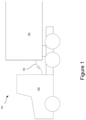
- Figure 1 illustrates a wireless communication system 100 for a truck 102 and a trailer 104.
- a high-speed wireless connector assembly 106 is connected between the truck 102 and the trailer 104 to enable high-speed communication between components of the truck 102 and trailer 104.
- a "vehicle” refers to a thing used for transporting goods and/or people, and may include motorized vehicles, such as trucks, automobiles, and/or motorized construction equipment, and non-motorized vehicles, such as trailers, carts, and/or dollies, for example.
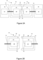
- Figure 2A illustrates the connector assembly 106, including components thereof, in a connected state
- Figure 2B illustrates the connector assembly 106 in a disconnected state.
- the connector assembly 106 is connected between the truck 102 and the trailer 104.
- the connector assembly 106 includes a connector assembly housing 108 that houses a first wireless communication module 112 and a second wireless communication module 120.
- the first wireless communication module 112 is coupled to electronic circuitry 114 in the truck 102 via a first wired connection 116
- the second wireless communication module 120 is coupled to electronic circuitry 122 in the trailer 104 via a second wired connection 124.
- the electronic circuitry 114, 122 may be coupled to various components, such as computing devices, sensors, and/or cameras for example.
- Forming a direct wired connection between the electronic circuitry 114, 122 in the different vehicles may have a number of disadvantages.
- One disadvantage is that it may be difficult to disconnect the wired connection to permit the vehicles to be separated from each other or connected to different vehicles.
- Many high-speed wired connection mechanisms are only capable of a limited number of connection / disconnection cycles without a decrease in the reliability of the high speed wired connection.
- the connector assembly 106 instead of forming a direct wired connection, positions the first wireless communication module 112 and a second wireless communication module 120 in close proximity to each other within the connector assembly housing 108. This permits the first wireless communication module 112 and the second wireless communication module 120 to establish a high-speed wireless communication link 134 therebetween without the performance degradation that may be exhibited by removable high speed wired connections.
- the first wireless communication module 112 includes a first transceiver 128 connected to a first antenna 126
- the second wireless communication module 120 includes a second transceiver 132 connected to a second antenna 130
- different components may be used, such as dedicated transmitters, receivers, and/or multiple antennas, for example.
- the first antenna 126 of the first wireless communication module 112 and the second antenna 130 of the second wireless communication module 120 are separated within the connector assembly 106 by a distance of less than 5 centimeters, but it should be understood that larger or smaller separation distances may be used, as desired.
- An advantage of positioning the first wireless communication module 112 and a second wireless communication module 120 in close proximity is that a high speed wireless communication link 134 can be established between the first wireless communication module 112 and the second wireless communication module 120 with a relatively small amount of power.
- the first wireless communication module 112 and/or second wireless communication module 120 convert digital data to radio-frequency (RF) waves (e.g., 60GHz or higher) and vice versa.
- RF radio-frequency
- the RF waves may further include modulation (e.g., quadrature amplitude modulation (QAM), to further increase a bit rate for the wireless communication link 134.
- modulation e.g., quadrature amplitude modulation (QAM)
- the wireless communication link 134 has a data transfer bandwidth of at least 5 Gigabits per second (Gb/s).
- Gb/s Gigabits per second
- the wireless communication link 134 is 10 Gb/s or more, but it should be understood that the connector assembly 106 may be configured to provide wireless communication links with higher or lower bandwidths, as desired.
- the circuitry 114 in the truck 102 and/or the circuitry 122 in the trailer 104 may include a multiplexer/demultiplexer that combines and/or separates a plurality of individual data signals, from different sensors for example, into a combined high-bandwidth data signal for transmission between the truck 102 and the trailer 104.
- Another advantage of this arrangement is that the transmission power for the first wireless communication module 112 and/or the second wireless communication module 120 can be kept relatively low. In addition to reducing power consumption, this also reduces the transmission range of the first wireless communication module 112 and/or the second wireless communication module 120, which in turn makes it more difficult for an unauthorized third party to access the wireless communication link 134.
- the connector assembly housing 108 is further configured to fully enclose the first wireless communication module 112 and the second wireless communication module 120 to isolate the first wireless communication module 112 and the second wireless communication module 120 from an environment 138 outside the connector assembly housing 108, such as moisture and other physical hazards.
- the connector assembly housing 108 may further include electromagnetic shielding 140 to electromagnetically isolate the first wireless communication module 112 and the second wireless communication module 120 from the environment 138.
- the electromagnetic shielding 140 provides several benefits. For example, the shielding 140 prevents outside electromagnetic interference with the first wireless communication module 112 and the second wireless communication module 120, which allows the wireless communication link 134 to operate at higher connection speeds more reliably.
- the shielding 140 increases security for the wireless communication link 134 by reducing the transmission of electromagnetic signals between the connector assembly housing 108 and the environment 138 in both directions, and avoids regulatory issues that may apply to higher power wireless communication.
- the connection assembly includes a first connector 108 that includes the first wireless communication module 112 and a second connector 118 that includes the second wireless communication module 120.
- the first connector 108 and the second connector 118 are configured to be selectively mechanically coupled to each other to form the connector assembly 106, and may also be selectively mechanically decoupled from each other, as desired. Because the first wireless communication module 112 and the second wireless communication module 120 do not form a direct wired connection, the number of connection / disconnection cycles for the first connector 108 and the second connector 118 are significantly increased.
- the first connector 108 forms a male connection interface 142 and the second connector 118 forms a female connection interface 144, but it should be understood that any number of different connection arrangements and mechanisms may be used, as desired.
- the truck 102 and the trailer 104 are able to move with respect to each other while coupled to each other without disconnecting the connector assembly 106.
- the connector assembly 106 forms a dedicated mechanical tether between the truck 102 and the trailer 104, with a suitable locking mechanism to maintain the connector assembly 106 and wireless communication link 134.
- a mechanical coupling operation of the truck 102 and the trailer 104 may form a suitable connector assembly as part of the coupling operation.
- Figures 3A and 3B are views of an alternative mechanical connector assembly 306 in a connected and disconnected state, according to some alternate embodiments.
- the truck 102 includes a fifth wheel 346 that couples to a kingpin 348 of the trailer 104 as part of a mechanical coupling operation.
- a first connector 310 coupled to the truck 102 near the fifth wheel 346 includes a male connection interface 342 positioned to be received by a female connection interface 344 of a second connector 318 coupled to the trailer 104 near the kingpin 348.
- the mechanical coupling operation between the truck 102 and the trailer 104 forms a connector assembly housing 308, which houses some or all of the components of the connector assembly 106 of Figures 1-2B above, or similar components, to provide a wireless communication link between the truck 102 and the trailer 104.
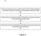
- FIG 4 is a flowchart of operations 400 for a method of wireless communication between a truck and a trailer using a connection assembly, such as the connector assemblies 106, 306 of Figures 1-3B for example, according to some embodiments.
- the operations 400 include connecting a first connector 108 of the truck to a second connector 118 of the trailer, Block 402, to position a first wireless communication module within a suitable wireless communication distance of a second wireless communication module.
- the operations 400 further include establishing a wireless communication link between the first wireless communication module and the second wireless communication module, Block 404.
- the operations 400 further include transferring data between the first wireless communication module and the second wireless communication module, Block 406.
- connecting the first connector to the second connector further includes forming a connector assembly housing that fully encloses the first wireless communication module and the second wireless communication module Block 408.
- fully enclosing the wireless communication modules may isolate the wireless communication modules from an environment outside the connector assembly housing.
- truck may be interpreted as denoting any tractor vehicle arranged to pull another vehicle unit to which it is connected via connection means such as a fifth wheel, kingpin, or drawbar.
- a trailer may be any vehicle arranged to be pulled by such a tractor vehicle.
- Figure 5A shows a vehicle combination 500 comprising a tractor unit 102 and a first semitrailer 104, i.e., a trailer without a front axle, with a connector assembly 106 according to the present disclosure arranged between the vehicles.
- Figure 5B shows a vehicle combination 500 comprising a truck 102 connected to a trailer with a front axle 104, also with a connector assembly 106 arranged between the vehicles.
- the vehicle combination in Figure 5A further comprises a dolly vehicle 510 arranged to be connected to the first semitrailer 104 as well as to a second semitrailer 510.
- a wireless communication system can be used also for communication between the first semitrailer 104 and the dolly vehicle 510, and / or between the dolly vehicle 510 and the second semitrailer 520.
- each vehicle in the vehicle combination may communicate with the vehicles immediately in front of and behind it through a wireless communication system 100 as herein described.
- a dolly vehicle 510 is herein seen as a form of trailer vehicle.
- the wireless communication system 100 is expected to be exposed to harsh environmental conditions such as high and low temperatures, precipitation such as rain or snow, and dust and dirt from the road, among other things. It may also be positioned adjacent to other electronic systems that produce and / or are sensitive to electromagnetic fields, which may result either in the wireless communication system 100 being affected by other electronic systems or other electronic systems being affected by the wireless communication system 100. It is thus important that the wireless communication system 100 be adequately shielded both mechanically and electromagnetically.
- a wireless communication system 100 for communication between a truck 102 and a trailer 104.
- the system comprises a connector assembly 106 coupled between the truck 102 and the trailer 104.
- the connector assembly comprises a connector assembly housing 108, a first wireless communication module 112 coupled to electronic circuitry 114 in the truck, and a second wireless communication module 120 coupled to electronic circuitry 122 in the trailer.
- the first wireless communication module and the second wireless communication module are disposed within the connector assembly housing, and the connector assembly housing comprises electromagnetic shielding means arranged to reduce a transmission of electromagnetic radiation between the first and/or second wireless communication modules and an environment 138 outside the connector assembly housing.
- the first wireless communication module and the second wireless communication module are configured to establish a wireless communication link 134 therebetween.
- the electromagnetic shielding means is arranged to reduce a transmission of electromagnetic radiation between the wireless communication modules on the inside of the connector assembly housing and the environment 138 outside the connector assembly housing. This substantially reduces the risk of the wireless communication system 100 being affected by interference from outside sources of electromagnetic radiation, as well as the risk of other devices mounted in proximity to the wireless communication system 100 being affected by the wireless communication system.
- the wireless communication system 100 is isolated, or at least heavily shielded, from the environment 138 this may affect which frequency bands can be used by the system, and possibly also the allowed transmit powers. If the system does not interact with the outside environment, it may be permitted for the system to use carrier frequency bands that are otherwise licensed or dedicated to other specific applications.
- a distance between the first wireless communication module 112 and the second wireless communication module 120 may be less than 5 centimeters. This short distance allows for communication at very high carrier frequencies, for example between 120 and 300 GHz or above. An advantage of using very high carrier frequencies is that the bandwidth of the available frequency bands is large, which in turn leads to a higher rate of information transfer through the wireless communication system.
- the connector assembly may also comprise a first connector 108 comprising the first wireless communication module, and a second connector 118 comprising the second wireless communication module.
- the first connector and the second connector are arranged to be mechanically coupled to each other to form the connector assembly 106.
- the connector assembly housing 108 may be configured to fully enclose the first wireless communication module 112 and the second wireless communication module 120. That is, the connector assembly housing 108 may form a mechanically sealed enclosure around the first and second wireless communication modules 112, 120.
- the term mechanically sealed should be interpreted to mean that the connector assembly housing 108 is designed to reduce the likelihood of objects from the environment, such as grains of sand, dust particles or water droplets, entering the connector assembly 106.
- Figure 2 A and B show the first connector 108 as forming a male connection interface or plug and the second connector 118 as forming a corresponding socket or a female connection interface. This would serve as a mechanical seal even though it is not hermetically sealed.
- connection interfaces may comprise screw treads arranged so that the connection interfaces can be screwed together in order to keep the connectors firmly connected.
- the connectors may be bayonet connectors.
- the connector assembly housing may also be arranged to be resistant to mechanical impacts. This resistance may include the connector assembly housing being resistant to breaking due to mechanical impact as well as the connectors being arranged to tolerate mechanical impact without disconnecting.
- the connector assembly housing may comprise a rigid or shock resistant layer, or a padded layer.
- the connector assembly housing should be resistant to deformation by mechanical impacts.
- An electromagnetic shielding means can block, absorb, and / or attenuate electromagnetic radiation.
- the electromagnetic shielding means may comprise an electrically conducting material, such as a metal foil or plate, a conductive foam, or a conductive mesh.
- An electrically conducting material is herein understood to be a material with an electrical conductivity similar to that of a metal or a semiconductor, or alternatively a material with an electrical conductivity above 100 ( ⁇ m) -1 .
- a conductive foam may according to one example be a metal foam. According to another example it may comprise smaller particles of a conducting material such as a metal or carbon black dispersed in a carrier material such as a polymer or resin.
- the choice of an electrically conducting material may be made in dependence of a frequency band of operation of the first and second wireless communication modules 112, 120.
- Components of the first and second wireless communication modules 112, 120 such as for example the transceiver 128, 132 and the antennas 126, 130, will be arranged to transmit and receive electromagnetic radiation in one or more frequency bands, a frequency band being an interval of frequencies between a minimum frequency and a maximum frequency.
- a frequency band may also be defined through a center frequency that is in the center of the frequency band along with the width of the frequency band.
- the one or more frequency bands in which the first and second wireless communication modules 112, 120 are arranged to transmit and receive electromagnetic radiation will herein be referred to as the frequency bands of operation of the wireless communication modules, or as the carrier frequency band.
- the hole size may be selected so that it is much smaller than a corresponding wavelength in air of electromagnetic radiation in a frequency band of operation of the first and second wireless communication modules 112, 120.
- the hole size may for example be 10 % or less of the wavelength.
- the electrically conductive material completely enclose the first and second wireless communication modules 112, 120, or at least not leaving any gaps of a size similar to or larger than the wavelength in air of the frequency band of operation. This may be particularly challenging if the wavelength is short, e.g., a few millimeters, as a hole or gap of a few millimeters could form e.g., due to a mechanical impact that deforms the connector assembly housing or due to the connectors 108, 118 being incorrectly connected.
- the electrically conducting material may be arranged to form an electrical contact between a first ground plane comprised in the first wireless communication module 112 and a second ground plane comprised in the second wireless communication module 120.
- the ground planes are taken to be electrically conducting planes or objects large enough to serve as a zero-voltage reference level.
- an electromagnetic shielding means comprising a conductive material to form an electrical contact between the two ground planes, the first and second wireless communication modules are completely enclosed, reducing the risk of leakage of electromagnetic waves.
- EBG electromagnetic band gap
- EBG structures are a type of metamaterial, i.e., a material that is formed from at least two different component materials arranged in a particular manner.
- electromagnetic waves in a certain frequency band are strongly attenuated and the propagation through the structure is reduced for frequencies in this frequency band.
- This frequency band is the electromagnetic band gap or stop band of the EBG structure.
- EBG structures may also be referred to as photonic band gap or PBG structures.
- An EBG structure is generally a periodic or quasi-periodic arrangement of elements with selected electromagnetic properties.
- a periodic arrangement refers to an arrangement where a basic building block is repeated at regular intervals in one, two or three dimensions
- quasiperiodic arrangement refers to an arrangement where the building blocks are arranged to have some local structure but no long-range order.
- an EBG structure may be an arrangement of elements in a pattern characterized by translational symmetry, rotational symmetry, or glide symmetry.
- the elements may comprise dielectric materials and be surrounded by a different dielectric material with a different dielectric constant.
- the elements may comprise a conducting material such as a metal or a conducting polymer and may be surrounded by a dielectric such as a non-conducting polymer or resin, or air.
- An example EBG structure 600 is shown in Figure 6A and B , comprising elements 610 arranged in a pattern that is periodic in two dimensions. In this case, the elements have the shape of rectangular cuboids, but they could also for example be cylindrical, conical, or mushroom-shaped.
- an EBG material could also comprise a block of a conducting material such as a metal or conducting polymer, with holes arranged in a pattern that is periodic or quasi-periodic in one, two or three dimensions.
- the holes may be filled with air, or with a solid dielectric such as a non-conducting polymer or resin.
- the electromagnetic shielding means comprised in the connector assembly housing may thus comprise an electromagnetic band gap, EBG, structure 600.
- the EBG structure 600 may as an example comprise a plurality of protruding elements 610 arranged periodically or quasi-periodically on a substrate 620.
- the protruding elements are to be surrounded by a dielectric, i.e., a material that is a poor electric conductor.
- a dielectric i.e., a material that is a poor electric conductor.
- the properties of this material can affect the function of the EBG structure. If air is used as the dielectric material, it is important to ensure that no other material enters the EBG structure and occupies the volume between the protruding elements, as this may impair the electromagnetic shielding properties of the EBG structure.
- the wireless communication system 100 may be exposed to environmental factors such as dirt and dust, water, road salt, etc. It may therefore be an advantage to construct the EBG structure so that a space surrounding the plurality of protruding elements 610 is at least partly filled with a solid dielectric material, or preferably completely filled with a solid dielectric material, such as a non-conducting polymer or resin. This can mitigate the problem of introduction and accumulation of other materials such as dust, dirt, or water within the EBG structure.
- An EBG structure causes attenuation of electromagnetic radiation at frequencies that fall in the band gap of the material.
- this band gap may advantageously be matched to at least one frequency band of operation of the first and second wireless communication modules 112, 120, i.e., the EBG structure 600 may be arranged to reduce transmission of electromagnetic radiation in a frequency band of operation of the first 112 and second 120 wireless communication modules.
- the band gap of an EBG structure is determined among other things by a size of the protruding elements 610, particularly a size in the direction or directions in which the EBG structure is periodic. In an EBG structure such as the one shown in Figure 6 A and B this size would be the length s of a side the rectangular cuboids in the EBG plane. For a cylindrical protruding element, it may instead be a radius or diameter of the cylinder.
- a size of the protruding elements 610 may be smaller than 10 % of a wavelength in air of electromagnetic radiation in a frequency band of operation of the first 112 and second 120 wireless communication modules.
- a truck 102 comprising a first connector 108.
- the first connector comprises a first wireless communication module 112 coupled to electronic circuitry 114 in the truck and is arranged to connect to a second connector 118 comprising a second wireless communication module 120.
- the first and second connectors are arranged to be mechanically connected to form a connector assembly 106 comprising a connector assembly housing 108, where the connector assembly housing comprises an electromagnetic shielding means arranged to reduce a transmission of electromagnetic radiation between the first and second wireless communication modules 112, 120 and an environment 138 outside the connector assembly housing 108.
- a trailer 104 comprising a second connector 118.
- the second connector comprises a second wireless communication module 120 coupled to electronic circuitry 122 in the trailer and is arranged to connect to a first connector 108 comprising a first wireless communication module 112.
- the first and second connectors are arranged to be mechanically connected to form a connector assembly 106 comprising a connector assembly housing 108.
- the connector assembly housing comprises an electromagnetic shielding means arranged to reduce a transmission of electromagnetic radiation between the first and second wireless communication modules 112, 120 and an environment 138 outside the connector assembly housing 108.
- Figure 4 illustrates a method of wireless communication between a truck 102 and a trailer 104.
- the truck 102 comprises a first connector 108 and the trailer 104 comprises a second connector 118.
- the first and second connectors 108, 118 comprise respective first 112 and second 120 wireless communication modules, where the first wireless communication module 112 is connected to electronic circuitry 114 in the truck 102 and the second wireless communication module 120 is connected to electronic circuitry 122 in the trailer.
- the first and second connectors are arranged to be mechanically connected to form a connector assembly 106 comprising a connector assembly housing 108.
- the connector assembly housing comprises an electromagnetic shielding means arranged to reduce a transmission of electromagnetic radiation between the first and second wireless communication modules 112, 120 and an environment 138 outside the connector assembly housing 108.
- the method comprises connecting 402 the first connector 108 to the second connector 118, establishing 404 a wireless communication link 134 between the first wireless communication module 112 and the second wireless communication module 120, and transferring 406 data between the first wireless communication module 112 and the second wireless communication module 120.
- the terms “comprise”, “comprising”, “comprises”, “include”, “including”, “includes”, “have”, “has”, “having”, or variants thereof are open-ended, and include one or more stated features, integers, elements, steps, components or functions but do not preclude the presence or addition of one or more other features, integers, elements, steps, components, functions or groups thereof.
- the common abbreviation “e.g.”, which derives from the Latin phrase “exempli gratia” may be used to introduce or specify a general example or examples of a previously mentioned item, and is not intended to be limiting of such item.
- the common abbreviation “i.e.”, which derives from the Latin phrase “id est,” may be used to specify a particular item from a more general recitation.
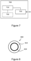
- FIG. 7 schematically illustrates, in terms of a number of functional units, the components of a control unit 700 according to embodiments of the discussions herein.
- This control unit may be comprised in a vehicle 102, 104 or vehicle combination 500.
- Processing circuitry 710 is provided using any combination of one or more of a suitable central processing unit CPU, multiprocessor, microcontroller, digital signal processor DSP, etc., capable of executing software instructions stored in a computer program product, e.g., in the form of a storage medium 730.
- the processing circuitry 710 may further be provided as at least one application specific integrated circuit ASIC, or field programmable gate array FPGA.
- processing circuitry 710 is configured to cause the control unit 700 to perform a set of operations, or steps, such as the methods discussed in connection to Figure 4 .
- the storage medium 730 may store the set of operations
- the processing circuitry 710 may be configured to retrieve the set of operations from the storage medium 730 to cause the control unit 700 to perform the set of operations.
- the set of operations may be provided as a set of executable instructions.
- the processing circuitry 710 is thereby arranged to execute methods as herein disclosed.
- control unit 700 for controlling communication between a truck 102 and a tractor 104 via a wireless communication system 100, the control unit comprising processing circuitry 710, an interface 720 coupled to the processing circuitry 710, and a memory 730 coupled to the processing circuitry 710, wherein the memory comprises machine readable computer program instructions that, when executed by the processing circuitry, causes the control unit to perform the methods discussed above in connection to Figure 4 .
- the storage medium 730 may also comprise persistent storage, which, for example, can be any single one or combination of magnetic memory, optical memory, solid state memory or even remotely mounted memory.
- the control unit 700 may further comprise an interface 720 for communications with at least one external device.
- the interface 720 may comprise one or more transmitters and receivers, comprising analogue and digital components and a suitable number of ports for wireline or wireless communication.
- the processing circuitry 710 controls the general operation of the control unit 700, e.g., by sending data and control signals to the interface 720 and the storage medium 730, by receiving data and reports from the interface 720, and by retrieving data and instructions from the storage medium 730.
- Other components, as well as the related functionality, of the control node are omitted in order not to obscure the concepts presented herein.
- Figure 8 illustrates a computer readable medium 810 carrying a computer program comprising program code means 820 for performing the methods illustrated in Figure 4 , when said program product is run on a computer.
- the computer readable medium and the code means may together form a computer program product 800.
Landscapes
- Engineering & Computer Science (AREA)
- Computer Networks & Wireless Communication (AREA)
- Signal Processing (AREA)
- Physics & Mathematics (AREA)
- Electromagnetism (AREA)
- Microelectronics & Electronic Packaging (AREA)
- Near-Field Transmission Systems (AREA)
- Mobile Radio Communication Systems (AREA)
- Transceivers (AREA)
Claims (14)
- Drahtloses Kommunikationssystem (100) für die Kommunikation zwischen einem Lastkraftwagen (102) und einem Anhänger (104), wobei das System umfasst:eine Verbinderanordnung (106), die zwischen dem Lastkraftwagen (102) und dem Anhänger (104) gekoppelt ist, wobei die Verbinderanordnung ein Verbinderanordnungsgehäuse (108) umfasst;ein erstes drahtloses Kommunikationsmodul (112), das mit einer elektronischen Schaltung (114) in dem Lastkraftwagen gekoppelt ist; undein zweites drahtloses Kommunikationsmodul (120), das mit einer elektronischen Schaltung (122) im Anhänger verbunden ist,wobei das erste drahtlose Kommunikationsmodul und das zweite drahtlose Kommunikationsmodul innerhalb des Verbinderanordnungsgehäuses angeordnet sind,wobei das Verbinderanordnungsgehäuse elektromagnetische Abschirmmittel umfasst, die so angeordnet sind, dass sie eine Übertragung von elektromagnetischer Strahlung zwischen dem ersten und dem zweiten drahtlosen Kommunikationsmodul und einer Umgebung (138) außerhalb des Verbinderanordnungsgehäuses reduzieren, undwobei das erste drahtlose Kommunikationsmodul und das zweite drahtlose Kommunikationsmodul so konfiguriert sind, dass sie eine drahtlose Kommunikationsverbindung (134) zwischen sich herstellen.
- Drahtlose Kommunikationssystem (100) nach Anspruch 1, wobei das Verbinderbaugruppengehäuse (108) so konfiguriert ist, dass es das erste drahtlose Kommunikationsmodul (112) und das zweite drahtlose Kommunikationsmodul (120) vollständig umschließt, um eine mechanisch abgedichtete Umhüllung um das erste und das zweite drahtlose Kommunikationsmodul (112, 120) zu bilden.
- Drahtlose Kommunikationssystem nach Anspruch 1 oder 2, wobei die elektromagnetischen Abschirmmittel ein elektrisch leitendes Material umfassen.
- Drahtlose Kommunikationssystem (100) nach Anspruch 3, wobei das elektrisch leitende Material so angeordnet ist, dass es einen elektrischen Kontakt zwischen einer ersten Masseebene, die in dem ersten Kommunikationsmodul enthalten ist, und einer zweiten Masseebene, die in dem zweiten Kommunikationsmodul enthalten ist, bildet.
- Drahtlose Kommunikationssystem (100) nach einem der vorhergehenden Ansprüche, wobei die elektromagnetischen Abschirmmittel eine elektromagnetische Bandlücken(EBG)-Struktur (600) umfassen.
- Drahtlose Kommunikationssystem (100) nach Anspruch 5, wobei die EBG-Struktur (600) so angeordnet ist, dass sie die Übertragung von elektromagnetischer Strahlung in einem Betriebsfrequenzband des ersten (112) und zweiten (120) drahtlosen Kommunikationsmoduls reduziert.
- Drahtlose Kommunikationssystem (100) nach Anspruch 5 oder 6, wobei die EBG-Struktur (600) eine Vielzahl von hervorstehenden Elementen (610) umfasst, die periodisch oder quasi-periodisch auf einem Substrat (620) angeordnet sind.
- Drahtlose Kommunikationssystem (100) nach Anspruch 7, wobei ein Raum, der die Vielzahl von vorstehenden Elementen (610) umgibt, zumindest teilweise mit einem dielektrischen Material gefüllt ist.
- Drahtlose Kommunikationssystem (100) nach Anspruch 7 oder 8, wobei eine Größe der vorstehenden Elemente (610) kleiner ist als 10 % einer Wellenlänge in Luft von elektromagnetischer Strahlung in einem Frequenzband des Betriebs des ersten (112) und zweiten (120) drahtlosen Kommunikationsmoduls.
- Drahtlose Kommunikationssystem (100) nach einem der vorhergehenden Ansprüche, wobei ein Abstand zwischen dem ersten drahtlosen Kommunikationsmodul (112) und dem zweiten drahtlosen Kommunikationsmodul (120) weniger als 5 Zentimeter beträgt.
- Drahtlose Kommunikationssystem (100) nach einem der vorhergehenden Ansprüche, wobei die Verbinderanordnung weiterhin umfasst:einen ersten Verbinder (108), der das erste drahtlose Kommunikationsmodul enthält; undeinen zweiten Steckverbinder (118), der das zweite drahtlose Kommunikationsmodul enthält,wobei der erste Verbinder und der zweite Verbinder so angeordnet sind, dass sie mechanisch miteinander gekoppelt werden, um die Verbinderanordnung (106) zu bilden.
- Lastkraftwagen (102), der einen ersten Verbinder (108) umfasst, wobei der erste Verbinder ein erstes drahtloses Kommunikationsmodul (112) umfasst, das mit einer elektronischen Schaltung (114) in dem Lastkraftwagen gekoppelt ist, wobei der erste Verbinder (108) so angeordnet ist, dass er mit einem zweiten Verbinder (118) verbunden werden kann, der ein zweites drahtloses Kommunikationsmodul (120) umfasst, der erste und der zweite Verbinder angeordnet sind, um mechanisch verbunden zu werden, um eine Verbinderanordnung (106) zu bilden, die ein Verbinderanordnungsgehäuse (108) umfasst, dadurch gekennzeichnet, dass das Verbinderanordnungsgehäuse ein elektromagnetisches Abschirmmittel umfasst, das angeordnet ist, um eine Übertragung von elektromagnetischer Strahlung zwischen dem ersten und dem zweiten drahtlosen Kommunikationsmodul (112, 120) und einer Umgebung (138) außerhalb des Verbinderanordnungsgehäuses (108) zu reduzieren.
- Anhänger (104), der einen zweiten Verbinder (118) umfasst, wobei der zweite Verbinder ein zweites drahtloses Kommunikationsmodul (120) umfasst, das mit einer elektronischen Schaltung (122) im Anhänger gekoppelt ist, wobei der zweite Verbinder (118) so angeordnet ist, dass er mit einem ersten Verbinder (108) verbunden wird, der ein erstes drahtloses Kommunikationsmodul (112) umfasst, der erste und der zweite Verbinder angeordnet sind, um mechanisch verbunden zu werden, um eine Verbinderanordnung (106) zu bilden, die ein Verbinderanordnungsgehäuse (108) umfasst, dadurch gekennzeichnet, dass das Verbinderanordnungsgehäuse ein elektromagnetisches Abschirmmittel umfasst, das angeordnet ist, um eine Übertragung von elektromagnetischer Strahlung zwischen dem ersten und dem zweiten drahtlosen Kommunikationsmodul (112, 120) und einer Umgebung (138) außerhalb des Verbinderanordnungsgehäuses (108) zu reduzieren.
- Verfahren zur drahtlosen Kommunikation zwischen einem Lastkraftwagen (102) und einem Anhänger (104), wobei der Lastkraftwagen (102) einen ersten Verbinder (108) und der Anhänger (104) einen zweiten Verbinder (118) umfasst, wobei der erste und der zweite Verbinder (108, 118) jeweils ein erstes (112) und ein zweites (120) drahtloses Kommunikationsmodul umfassen, wobei das erste drahtlose Kommunikationsmodul (112) mit einer elektronischen Schaltung (114) im Lastkraftwagen (102) verbunden ist und das zweite drahtlose Kommunikationsmodul (120) mit einer elektronischen Schaltung (122) im Anhänger verbunden ist, die ersten und zweiten Verbinder angeordnet sind, um mechanisch verbunden zu werden, um eine Verbinderanordnung (106) zu bilden, die ein Verbinderanordnungsgehäuse (108) umfasst, wobei das Verbinderanordnungsgehäuse ein elektromagnetisches Abschirmmittel umfasst, das angeordnet ist, um eine Übertragung von elektromagnetischer Strahlung zwischen den ersten und zweiten drahtlosen Kommunikationsmodulen (112, 120) und einer Umgebung (138) außerhalb des Verbinderanordnungsgehäuses (108) zu reduzieren, wobei das Verfahren umfasst:Verbinden (402) des ersten Verbinders (108) mit dem zweiten Verbinder (118),Herstellen (404) einer drahtlosen Kommunikationsverbindung (134) zwischen dem ersten drahtlosen Kommunikationsmodul (112) und dem zweiten drahtlosen Kommunikationsmodul (120); undÜbertragung (406) von Daten zwischen dem ersten drahtlosen Kommunikationsmodul (112) und dem zweiten drahtlosen Kommunikationsmodul (120).
Applications Claiming Priority (1)
| Application Number | Priority Date | Filing Date | Title |
|---|---|---|---|
| PCT/IB2020/056276 WO2022003404A1 (en) | 2020-07-02 | 2020-07-02 | Connector assembly for high-speed wireless communication between vehicles |
Publications (3)
| Publication Number | Publication Date |
|---|---|
| EP3934290A1 EP3934290A1 (de) | 2022-01-05 |
| EP3934290C0 EP3934290C0 (de) | 2024-08-14 |
| EP3934290B1 true EP3934290B1 (de) | 2024-08-14 |
Family
ID=71579640
Family Applications (2)
| Application Number | Title | Priority Date | Filing Date |
|---|---|---|---|
| EP20739775.3A Active EP4176599B1 (de) | 2020-07-02 | 2020-07-02 | Verbinderanordnung für drahtlose hochgeschwindigkeitskommunikation zwischen fahrzeugen |
| EP21181377.9A Active EP3934290B1 (de) | 2020-07-02 | 2021-06-24 | Verbesserte verbinderanordnung für schnelle drahtlose kommunikation zwischen fahrzeugen |
Family Applications Before (1)
| Application Number | Title | Priority Date | Filing Date |
|---|---|---|---|
| EP20739775.3A Active EP4176599B1 (de) | 2020-07-02 | 2020-07-02 | Verbinderanordnung für drahtlose hochgeschwindigkeitskommunikation zwischen fahrzeugen |
Country Status (4)
| Country | Link |
|---|---|
| US (2) | US20230254011A1 (de) |
| EP (2) | EP4176599B1 (de) |
| CN (1) | CN113891644B (de) |
| WO (1) | WO2022003404A1 (de) |
Families Citing this family (3)
| Publication number | Priority date | Publication date | Assignee | Title |
|---|---|---|---|---|
| US11794540B2 (en) * | 2020-10-27 | 2023-10-24 | Clarion Corporation of America | Technologies for a harness connector with integrated wireless transceiver |
| CN119654585A (zh) * | 2022-08-31 | 2025-03-18 | 深圳引望智能技术有限公司 | 一种连接器、通信系统和车辆 |
| EP4357169A1 (de) * | 2022-10-19 | 2024-04-24 | Volvo Truck Corporation | System zur bereitstellung von kommunikation zwischen einem zugfahrzeug und einem gezogenen fahrzeug und verfahren dafür |
Family Cites Families (12)
| Publication number | Priority date | Publication date | Assignee | Title |
|---|---|---|---|---|
| US7142098B2 (en) * | 2003-09-05 | 2006-11-28 | Lang-Mekra North America, Llc | Wireless data transfer system for a tractor-trailer |
| US7932815B2 (en) | 2007-03-16 | 2011-04-26 | Intermec Ip Corp. | Wireless tractor-trailer communications |
| US7825782B2 (en) | 2007-03-20 | 2010-11-02 | Ford Global Technologies, Llc | Device and method for wireless vehicle communication |
| US7760077B2 (en) | 2007-06-05 | 2010-07-20 | Qualcomm Incorporated | Establishing and securing a unique wireless RF link between a tractor and a trailer using a wired connection |
| US9834133B2 (en) | 2014-07-24 | 2017-12-05 | R. A. Phillips Industries, Inc. | Wireless link and a vehicle electrical system using the same |
| EP3269423A1 (de) * | 2016-07-13 | 2018-01-17 | BIOTRONIK SE & Co. KG | Implantierbares medizinisches gerät mit antenne für drahtlose kommunikation |
| US10168708B2 (en) * | 2017-03-30 | 2019-01-01 | GM Global Technology Operations LLC | Wireless vehicle-trailer interface system |
| KR102055364B1 (ko) * | 2018-02-28 | 2019-12-13 | 주식회사 아이티텔레콤 | V2x 통신 성능 계측 장치 |
| US20190315170A1 (en) * | 2018-04-13 | 2019-10-17 | Clinton Williams | Wireless Trailer Signal System |
| US10924905B2 (en) * | 2018-05-25 | 2021-02-16 | Paccar Inc | Near field connection for secure tractor trailer communication, and associated systems and methods |
| JP7319807B2 (ja) * | 2019-03-29 | 2023-08-02 | キヤノン株式会社 | 通信装置、通信方法、及び、プログラム |
| US10978793B2 (en) * | 2019-05-09 | 2021-04-13 | Harada Industry Of America, Inc. | Antenna with gain reduction |
-
2020
- 2020-07-02 EP EP20739775.3A patent/EP4176599B1/de active Active
- 2020-07-02 WO PCT/IB2020/056276 patent/WO2022003404A1/en not_active Ceased
- 2020-07-02 US US18/003,813 patent/US20230254011A1/en not_active Abandoned
-
2021
- 2021-06-24 EP EP21181377.9A patent/EP3934290B1/de active Active
- 2021-07-01 CN CN202110746938.8A patent/CN113891644B/zh active Active
- 2021-07-02 US US17/366,819 patent/US12021607B2/en active Active
Also Published As
| Publication number | Publication date |
|---|---|
| EP4176599B1 (de) | 2026-03-25 |
| EP3934290C0 (de) | 2024-08-14 |
| CN113891644B (zh) | 2025-11-14 |
| EP3934290A1 (de) | 2022-01-05 |
| EP4176599A1 (de) | 2023-05-10 |
| WO2022003404A1 (en) | 2022-01-06 |
| CN113891644A (zh) | 2022-01-04 |
| US20220006516A1 (en) | 2022-01-06 |
| US12021607B2 (en) | 2024-06-25 |
| US20230254011A1 (en) | 2023-08-10 |
Similar Documents
| Publication | Publication Date | Title |
|---|---|---|
| EP3934290B1 (de) | Verbesserte verbinderanordnung für schnelle drahtlose kommunikation zwischen fahrzeugen | |
| US20200295430A1 (en) | Dielectric Waveguide Radar Signal Distribution | |
| CN101145811B (zh) | 通信系统、通信装置以及高频耦合器 | |
| US9866272B2 (en) | Communication system comprising a connector having first and second waveguides disposed in proximity to each other for coupling millimeter-wave data signals | |
| TWI380614B (de) | ||
| US20190007786A1 (en) | Staggered Back-to-Back Launch Topology with Diagonal Waveguides for Field Confined Near Field Communication System | |
| AU2003245376B2 (en) | Exciter-excitation system and methods for communications | |
| CN112868136B (zh) | 车辆用天线系统 | |
| EP2721742B1 (de) | Magnetisch-induktiver wellenleiter | |
| CN108475848A (zh) | 用于提供模块化天线总成的装置、系统和方法 | |
| US20200321710A1 (en) | Virtual Radar Array Having Reduced Size | |
| CA3129153A1 (en) | Antenna system for small form factor | |
| EP3506418B1 (de) | Gecrimpter mm-wellenleiter-abzweigverbinder | |
| CN113508499B (zh) | 同轴连接器和电缆组件 | |
| CN115863974B (zh) | 能量选择天线及其设计方法 | |
| US11575749B2 (en) | Low-weight single mm-wave dielectric waveguide interconnect architecture in autonomous cars | |
| JP2008512948A (ja) | 隠蔽式平板状アンテナ | |
| US12476382B2 (en) | Terahertz carrier sending apparatus and terahertz carrier receiving apparatus | |
| EP2538572B1 (de) | Kommunikationsvorrichtung | |
| US20130307747A1 (en) | Vehicular antenna | |
| EP4016740B1 (de) | Durch doppelleitung gespeiste dipolgruppenantenne | |
| EP2854215B1 (de) | Antennenanordnung mit einer Antenneneinheit und Verbindungseinheit | |
| CN220985673U (zh) | 增强无人机图传通信模组天线辐射角信号强度的系统 | |
| US9246548B2 (en) | Electromagnetic coupling of electronic devices using resonant terminations that shift resonant frequencies | |
| CN114076915B (zh) | 探测装置和探测装置的制造方法 |
Legal Events
| Date | Code | Title | Description |
|---|---|---|---|
| PUAI | Public reference made under article 153(3) epc to a published international application that has entered the european phase |
Free format text: ORIGINAL CODE: 0009012 |
|
| STAA | Information on the status of an ep patent application or granted ep patent |
Free format text: STATUS: THE APPLICATION HAS BEEN PUBLISHED |
|
| AK | Designated contracting states |
Kind code of ref document: A1 Designated state(s): AL AT BE BG CH CY CZ DE DK EE ES FI FR GB GR HR HU IE IS IT LI LT LU LV MC MK MT NL NO PL PT RO RS SE SI SK SM TR |
|
| B565 | Issuance of search results under rule 164(2) epc |
Effective date: 20211012 |
|
| STAA | Information on the status of an ep patent application or granted ep patent |
Free format text: STATUS: REQUEST FOR EXAMINATION WAS MADE |
|
| 17P | Request for examination filed |
Effective date: 20220606 |
|
| RBV | Designated contracting states (corrected) |
Designated state(s): AL AT BE BG CH CY CZ DE DK EE ES FI FR GB GR HR HU IE IS IT LI LT LU LV MC MK MT NL NO PL PT RO RS SE SI SK SM TR |
|
| STAA | Information on the status of an ep patent application or granted ep patent |
Free format text: STATUS: EXAMINATION IS IN PROGRESS |
|
| 17Q | First examination report despatched |
Effective date: 20230206 |
|
| GRAP | Despatch of communication of intention to grant a patent |
Free format text: ORIGINAL CODE: EPIDOSNIGR1 |
|
| STAA | Information on the status of an ep patent application or granted ep patent |
Free format text: STATUS: GRANT OF PATENT IS INTENDED |
|
| INTG | Intention to grant announced |
Effective date: 20240304 |
|
| GRAS | Grant fee paid |
Free format text: ORIGINAL CODE: EPIDOSNIGR3 |
|
| GRAA | (expected) grant |
Free format text: ORIGINAL CODE: 0009210 |
|
| STAA | Information on the status of an ep patent application or granted ep patent |
Free format text: STATUS: THE PATENT HAS BEEN GRANTED |
|
| AK | Designated contracting states |
Kind code of ref document: B1 Designated state(s): AL AT BE BG CH CY CZ DE DK EE ES FI FR GB GR HR HU IE IS IT LI LT LU LV MC MK MT NL NO PL PT RO RS SE SI SK SM TR |
|
| REG | Reference to a national code |
Ref country code: GB Ref legal event code: FG4D |
|
| REG | Reference to a national code |
Ref country code: CH Ref legal event code: EP |
|
| REG | Reference to a national code |
Ref country code: DE Ref legal event code: R096 Ref document number: 602021017090 Country of ref document: DE |
|
| REG | Reference to a national code |
Ref country code: IE Ref legal event code: FG4D |
|
| U01 | Request for unitary effect filed |
Effective date: 20240815 |
|
| U07 | Unitary effect registered |
Designated state(s): AT BE BG DE DK EE FI FR IT LT LU LV MT NL PT SE SI Effective date: 20240828 |
|
| PG25 | Lapsed in a contracting state [announced via postgrant information from national office to epo] |
Ref country code: NO Free format text: LAPSE BECAUSE OF FAILURE TO SUBMIT A TRANSLATION OF THE DESCRIPTION OR TO PAY THE FEE WITHIN THE PRESCRIBED TIME-LIMIT Effective date: 20241114 |
|
| PG25 | Lapsed in a contracting state [announced via postgrant information from national office to epo] |
Ref country code: PL Free format text: LAPSE BECAUSE OF FAILURE TO SUBMIT A TRANSLATION OF THE DESCRIPTION OR TO PAY THE FEE WITHIN THE PRESCRIBED TIME-LIMIT Effective date: 20240814 Ref country code: GR Free format text: LAPSE BECAUSE OF FAILURE TO SUBMIT A TRANSLATION OF THE DESCRIPTION OR TO PAY THE FEE WITHIN THE PRESCRIBED TIME-LIMIT Effective date: 20241115 |
|
| PG25 | Lapsed in a contracting state [announced via postgrant information from national office to epo] |
Ref country code: IS Free format text: LAPSE BECAUSE OF FAILURE TO SUBMIT A TRANSLATION OF THE DESCRIPTION OR TO PAY THE FEE WITHIN THE PRESCRIBED TIME-LIMIT Effective date: 20241214 |
|
| PG25 | Lapsed in a contracting state [announced via postgrant information from national office to epo] |
Ref country code: HR Free format text: LAPSE BECAUSE OF FAILURE TO SUBMIT A TRANSLATION OF THE DESCRIPTION OR TO PAY THE FEE WITHIN THE PRESCRIBED TIME-LIMIT Effective date: 20240814 |
|
| PG25 | Lapsed in a contracting state [announced via postgrant information from national office to epo] |
Ref country code: RS Free format text: LAPSE BECAUSE OF FAILURE TO SUBMIT A TRANSLATION OF THE DESCRIPTION OR TO PAY THE FEE WITHIN THE PRESCRIBED TIME-LIMIT Effective date: 20241114 Ref country code: ES Free format text: LAPSE BECAUSE OF FAILURE TO SUBMIT A TRANSLATION OF THE DESCRIPTION OR TO PAY THE FEE WITHIN THE PRESCRIBED TIME-LIMIT Effective date: 20240814 |
|
| PG25 | Lapsed in a contracting state [announced via postgrant information from national office to epo] |
Ref country code: RS Free format text: LAPSE BECAUSE OF FAILURE TO SUBMIT A TRANSLATION OF THE DESCRIPTION OR TO PAY THE FEE WITHIN THE PRESCRIBED TIME-LIMIT Effective date: 20241114 Ref country code: PL Free format text: LAPSE BECAUSE OF FAILURE TO SUBMIT A TRANSLATION OF THE DESCRIPTION OR TO PAY THE FEE WITHIN THE PRESCRIBED TIME-LIMIT Effective date: 20240814 Ref country code: NO Free format text: LAPSE BECAUSE OF FAILURE TO SUBMIT A TRANSLATION OF THE DESCRIPTION OR TO PAY THE FEE WITHIN THE PRESCRIBED TIME-LIMIT Effective date: 20241114 Ref country code: IS Free format text: LAPSE BECAUSE OF FAILURE TO SUBMIT A TRANSLATION OF THE DESCRIPTION OR TO PAY THE FEE WITHIN THE PRESCRIBED TIME-LIMIT Effective date: 20241214 Ref country code: HR Free format text: LAPSE BECAUSE OF FAILURE TO SUBMIT A TRANSLATION OF THE DESCRIPTION OR TO PAY THE FEE WITHIN THE PRESCRIBED TIME-LIMIT Effective date: 20240814 Ref country code: GR Free format text: LAPSE BECAUSE OF FAILURE TO SUBMIT A TRANSLATION OF THE DESCRIPTION OR TO PAY THE FEE WITHIN THE PRESCRIBED TIME-LIMIT Effective date: 20241115 Ref country code: ES Free format text: LAPSE BECAUSE OF FAILURE TO SUBMIT A TRANSLATION OF THE DESCRIPTION OR TO PAY THE FEE WITHIN THE PRESCRIBED TIME-LIMIT Effective date: 20240814 |
|
| PG25 | Lapsed in a contracting state [announced via postgrant information from national office to epo] |
Ref country code: SM Free format text: LAPSE BECAUSE OF FAILURE TO SUBMIT A TRANSLATION OF THE DESCRIPTION OR TO PAY THE FEE WITHIN THE PRESCRIBED TIME-LIMIT Effective date: 20240814 |
|
| PG25 | Lapsed in a contracting state [announced via postgrant information from national office to epo] |
Ref country code: CZ Free format text: LAPSE BECAUSE OF FAILURE TO SUBMIT A TRANSLATION OF THE DESCRIPTION OR TO PAY THE FEE WITHIN THE PRESCRIBED TIME-LIMIT Effective date: 20240814 |
|
| PG25 | Lapsed in a contracting state [announced via postgrant information from national office to epo] |
Ref country code: SK Free format text: LAPSE BECAUSE OF FAILURE TO SUBMIT A TRANSLATION OF THE DESCRIPTION OR TO PAY THE FEE WITHIN THE PRESCRIBED TIME-LIMIT Effective date: 20240814 |
|
| PLBE | No opposition filed within time limit |
Free format text: ORIGINAL CODE: 0009261 |
|
| STAA | Information on the status of an ep patent application or granted ep patent |
Free format text: STATUS: NO OPPOSITION FILED WITHIN TIME LIMIT |
|
| 26N | No opposition filed |
Effective date: 20250515 |
|
| U20 | Renewal fee for the european patent with unitary effect paid |
Year of fee payment: 5 Effective date: 20250624 |
|
| REG | Reference to a national code |
Ref country code: CH Ref legal event code: H13 Free format text: ST27 STATUS EVENT CODE: U-0-0-H10-H13 (AS PROVIDED BY THE NATIONAL OFFICE) Effective date: 20260127 |
|
| PG25 | Lapsed in a contracting state [announced via postgrant information from national office to epo] |
Ref country code: MC Free format text: LAPSE BECAUSE OF FAILURE TO SUBMIT A TRANSLATION OF THE DESCRIPTION OR TO PAY THE FEE WITHIN THE PRESCRIBED TIME-LIMIT Effective date: 20240814 |
|
| GBPC | Gb: european patent ceased through non-payment of renewal fee |
Effective date: 20250624 |
|
| PG25 | Lapsed in a contracting state [announced via postgrant information from national office to epo] |
Ref country code: GB Free format text: LAPSE BECAUSE OF NON-PAYMENT OF DUE FEES Effective date: 20250624 |
|
| PG25 | Lapsed in a contracting state [announced via postgrant information from national office to epo] |
Ref country code: IE Free format text: LAPSE BECAUSE OF NON-PAYMENT OF DUE FEES Effective date: 20250624 |
|
| PG25 | Lapsed in a contracting state [announced via postgrant information from national office to epo] |
Ref country code: RO Free format text: LAPSE BECAUSE OF FAILURE TO SUBMIT A TRANSLATION OF THE DESCRIPTION OR TO PAY THE FEE WITHIN THE PRESCRIBED TIME-LIMIT Effective date: 20240814 |