EP3934087A1 - Electric motor driving device - Google Patents
Electric motor driving device Download PDFInfo
- Publication number
- EP3934087A1 EP3934087A1 EP19916640.6A EP19916640A EP3934087A1 EP 3934087 A1 EP3934087 A1 EP 3934087A1 EP 19916640 A EP19916640 A EP 19916640A EP 3934087 A1 EP3934087 A1 EP 3934087A1
- Authority
- EP
- European Patent Office
- Prior art keywords
- board
- disposed
- connector
- case
- connection
- Prior art date
- Legal status (The legal status is an assumption and is not a legal conclusion. Google has not performed a legal analysis and makes no representation as to the accuracy of the status listed.)
- Granted
Links
Images


Classifications
-
- H—ELECTRICITY
- H02—GENERATION; CONVERSION OR DISTRIBUTION OF ELECTRIC POWER
- H02M—APPARATUS FOR CONVERSION BETWEEN AC AND AC, BETWEEN AC AND DC, OR BETWEEN DC AND DC, AND FOR USE WITH MAINS OR SIMILAR POWER SUPPLY SYSTEMS; CONVERSION OF DC OR AC INPUT POWER INTO SURGE OUTPUT POWER; CONTROL OR REGULATION THEREOF
- H02M7/00—Conversion of AC power input into DC power output; Conversion of DC power input into AC power output
- H02M7/003—Constructional details, e.g. physical layout, assembly, wiring or busbar connections
-
- H—ELECTRICITY
- H02—GENERATION; CONVERSION OR DISTRIBUTION OF ELECTRIC POWER
- H02K—DYNAMO-ELECTRIC MACHINES
- H02K11/00—Structural association of dynamo-electric machines with electric components or with devices for shielding, monitoring or protection
- H02K11/30—Structural association with control circuits or drive circuits
- H02K11/33—Drive circuits, e.g. power electronics
-
- H—ELECTRICITY
- H02—GENERATION; CONVERSION OR DISTRIBUTION OF ELECTRIC POWER
- H02M—APPARATUS FOR CONVERSION BETWEEN AC AND AC, BETWEEN AC AND DC, OR BETWEEN DC AND DC, AND FOR USE WITH MAINS OR SIMILAR POWER SUPPLY SYSTEMS; CONVERSION OF DC OR AC INPUT POWER INTO SURGE OUTPUT POWER; CONTROL OR REGULATION THEREOF
- H02M7/00—Conversion of AC power input into DC power output; Conversion of DC power input into AC power output
- H02M7/42—Conversion of DC power input into AC power output without possibility of reversal
- H02M7/44—Conversion of DC power input into AC power output without possibility of reversal by static converters
-
- H—ELECTRICITY
- H05—ELECTRIC TECHNIQUES NOT OTHERWISE PROVIDED FOR
- H05K—PRINTED CIRCUITS; CASINGS OR CONSTRUCTIONAL DETAILS OF ELECTRIC APPARATUS; MANUFACTURE OF ASSEMBLAGES OF ELECTRICAL COMPONENTS
- H05K5/00—Casings, cabinets or drawers for electric apparatus
- H05K5/0026—Casings, cabinets or drawers for electric apparatus provided with connectors and printed circuit boards [PCB], e.g. automotive electronic control units
-
- H—ELECTRICITY
- H05—ELECTRIC TECHNIQUES NOT OTHERWISE PROVIDED FOR
- H05K—PRINTED CIRCUITS; CASINGS OR CONSTRUCTIONAL DETAILS OF ELECTRIC APPARATUS; MANUFACTURE OF ASSEMBLAGES OF ELECTRICAL COMPONENTS
- H05K7/00—Constructional details common to different types of electric apparatus
- H05K7/14—Mounting supporting structure in casing or on frame or rack
- H05K7/1422—Printed circuit boards receptacles, e.g. stacked structures, electronic circuit modules or box like frames
- H05K7/1427—Housings
- H05K7/1432—Housings specially adapted for power drive units or power converters
- H05K7/14322—Housings specially adapted for power drive units or power converters wherein the control and power circuits of a power converter are arranged within the same casing
-
- H—ELECTRICITY
- H02—GENERATION; CONVERSION OR DISTRIBUTION OF ELECTRIC POWER
- H02K—DYNAMO-ELECTRIC MACHINES
- H02K2211/00—Specific aspects not provided for in the other groups of this subclass relating to measuring or protective devices or electric components
- H02K2211/03—Machines characterised by circuit boards, e.g. pcb
Definitions
- the present invention relates to a device for driving a motor having an improved structure.
- the device for driving a motor refers to a device capable of controlling the speed of a motor with high efficiency by supplying power supplied from an external power source to the motor by varying a voltage and a frequency.
- the conventional device for driving a motor forms an overall exterior appearance with a case body and a cover, and a circuit unit is accommodated in an internal space formed by the case body and the cover.
- a plurality of main circuit boards such as a power board, a filter board, a control board and/or a cap board are disposed, and a plurality of circuit boards are interconnected with a conductor such as a wire or a clamp structure for mutual electrical signal connection.
- a conductor such as a wire or a clamp structure for mutual electrical signal connection.
- these are interconnected by a cable composed of wires and connectors.
- the conventional board connection structure has a problem in that it is difficult to implement the automation of assembly, and the wire or cable generates noise signals like an antenna inside the device for driving a motor.
- the conventional device for driving a motor includes an inner case between the case body and the cover, there is a problem in that any one of the boards must be disposed on the lower side surface of the inner case for connection to the other board disposed on the case body. In such a board arrangement structure, noise may be generated because both boards face each other.
- the board is disposed on the upper side of the inner case to reduce such noise, wires or cables for connecting to other boards disposed on the case body are disposed to be long, thereby complicating the internal structure and increasing noise generation.
- an object of the present invention is to provide a device for driving a motor, which is capable of automating the assembly process and reducing the generation of internal noise by improving the internal structure of the device for driving a motor.
- the present invention provides a device for driving a motor, including a lower case having an accommodating space formed therein and an open upper side; an upper case closing an open surface of the lower case to form an inner space; a central case disposed in the lower case to partition an inner space formed by the lower case and the upper case; a first board disposed on the lower case and including a first connector; a second board disposed on the central case and including a second connector; and a connection board disposed in the inner space and including a first connection connector electrically connected to the first connector and a second connection connector electrically connected to the second connector to transmit electric signals between the boards.
- first board and the second board may be disposed parallel to a bottom surface of the lower case, and the connection board may be disposed perpendicular to a bottom surface of the lower case.
- the second board may be disposed on an upper side surface of the central case.
- first connector may be disposed on an upper side surface of the first board
- second connector may be disposed on a lower side surface of the second board
- the central case may be formed with a concave portion in which the connection board can be disposed on one side such that the connection board is disposed between an upper side surface of the first board and a lower side surface of the second board.
- connection board may further include a third connection connector electrically connected to the third connector, so as to transmit electric signals between the boards.
- first board, the second board and the third board may be disposed parallel to a bottom surface of the lower case, and the connection board may be disposed perpendicular to a bottom surface of the lower case.
- the first connector may be disposed on an upper side surface of the first board, wherein the second connector may be disposed on a lower side surface of the second board, wherein the third board may have a protrusion formed to protrude to one side, and the third connector may be disposed on an upper side surface of the protrusion, wherein the central case may be formed with a concave portion in which the connection board can be disposed on one side such that the connection board is disposed between an upper side surface of the first board and a lower side surface of the second board, and wherein the connection board may be formed in a U-shape opened downward such that the first connection connector is disposed on at least one of both sides, the third connection connector is disposed on a concave surface, and the second connection connector is disposed on an upper side surface.
- connection board may be fastened to the central case.
- the present invention enables automatic assembly and reduces internal noise at the same time by implementing the mutual electrical connection between main boards by a connection board without wires or cables.
- the present invention can secure space efficiency inside a device for driving a motor by changing the shape of an intermediate board and/or a central case such that the connection board can be disposed between the lowermost board and the uppermost board.
- FIG. 1 is a perspective view of the device for driving a motor according to an exemplary embodiment of the present invention
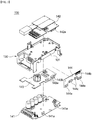
- FIG. 2 is an exploded perspective view in which the upper case and the lower case are separated in FIG. 1
- FIG. 3 is an exploded perspective view of the central case and the board unit illustrated in FIG. 2 .
- the device for driving a motor 100 may largely include a lower case 110, an upper case 120, a central case 130 and a board unit 140.
- the lower case 110 is a housing having an accommodating space formed therein and an open upper side, and a heat dissipation unit 111 or a cooling fan 112 may be disposed therein.
- the lower case 110 may be integrally formed with a heat dissipation part 111 to be described below by injection molding.
- the heat dissipation unit 111 is a device for absorbing heat of the board unit 140 to be described below and discharging the same to the outside, and it is also referred to as a heat sink.
- the cooling fan 112 supplies external air to the heat dissipation unit 111 and the board unit 140 to cool the heat, and at least one or more cooling fans may be disposed in the lower case 110.
- the upper case 120 may close the open surface of the lower case 110 to form an inner space of the device for driving a motor 100 according to an exemplary embodiment of the present invention.
- a plurality of slits 121 for dissipating heat may be formed on at least one side surface of the upper case 120.
- the central case 130 may be disposed on the lower case 110 to partition an inner space formed by the lower case 110 and the upper case 120.
- the central case 130 may be fastened to the lower case 110 and disposed in the inner space formed by the lower case 110 and the upper case 120, or it may be disposed between the upper case 120 and the lower case 110 to form an exterior appearance.
- the board unit 140 may include at least two or more boards that are distinguished according to their functions, and may include, for example, a first board 141, a second board 142 and a connection board 144.
- Each of the boards constituting the board unit 140 may be fixed to the lower case 110 or the central case 130 by bolt fastening and/or hook fastening.
- the first board 141 may be disposed on the lower case 110 and include a first connector 141a, and the first board 141 may be, for example, a power board.
- the power board may use a semiconductor device for power to have a function of generating a variable voltage and a variable frequency for driving a motor, a DC-link smoothing function for smoothing the input voltage, and a function of detecting a DC-link voltage and an inverter output current.
- IGBT In such a power board, IGBT, a power relay, gate driver IC, Hall-CT, DC Reactor, and a snubber capacitor may be mounted as main components.
- the second board 142 may be disposed on the central case 130 and include a second connector 142a, and the second board 142 may be, for example, a filter board.
- the filter board may have a filtering function to reduce noise components generated in the inverter from being introduced into the system.
- EMC choke In such a filter board, EMC choke, X-Capacitor, Y-Capacitor and Transformer may be mounted as main components.
- connection board 144 may be disposed in the inner space formed by the lower case 110 and the upper case 120, and include a first connection connector 144a electrically connected to the first connector 141a and a second connection connector 144b electrically connected to the second connector 142 to transmit electrical signals between the boards.
- the first board 141 and the second board 142 may be disposed parallel to the bottom surface of the lower case 110, and the connection board 144 may be disposed perpendicular to the bottom surface of the lower case 110.
- connection board 144 the second board 142 may be disposed on the upper side surface of the central case 130, and even in this structure, there are advantages in which the automatic assembly with the first board 141 is possible and noise generation is not problematic.
- connection board 144 may be disposed in a space where the first board 141 and the second board 142 face each other.
- the first connector 141a may be disposed on the upper side surface of the first board 141
- the second connector 142a may be disposed on the lower side surface of the second board 142
- the central case 130 may be formed with a concave portion 131 in which the connection board 144 may be disposed on one side thereof such that the connection board 144 is disposed between the upper side surface of the first board 141 and the lower side surface of the second board 141.
- effects such as internal space utilization, possibility of automatic assembly, productivity, noise reduction and the like may be further increased when another board is further added.
- the present invention may further include a third board 14, and in this case, structural features for the above-described connection board 144 may be further included.
- the third board 143 may be fastened to a support 113 disposed on the lower case 110 between the lower case 110 and the central case 130, and include a third connector 143a. That is, the third board 143 may be disposed between the first board 141 and the second board 142.
- the third board 143 may be a control board and have a controller function of generating a signal (PWM) for controlling the motor using an operation command, a speed command and voltage and current information.
- PWM a signal for controlling the motor using an operation command, a speed command and voltage and current information.
- a micro control unit may be mounted as a main component.
- connection board 144 may be disposed in the inner space formed by the lower case 110 and the upper case 120, and the connection board 144 may further include a third connection connector 144c electrically connected to the third connector 143a to transmit electrical signals between the boards.
- the first board 141, the second board 142 and the third board 143 may be disposed parallel to the bottom surface of the lower case 110, and the connection board 144 may be disposed perpendicular to the bottom surface of the lower case 110.
- connection board 144 may be disposed in a space where the first board 141 and the second board 142 face each other.
- the first connector 141a may disposed on the upper side surface of the first board 141
- the second connector 142a may be disposed on the lower side surface of the second board 142
- the third board 143 may have a protrusion 143b formed to protrude to one side.
- the third connector 143a may be disposed on the upper side surface of the protrusion 143b
- the central case 130 may be formed with a concave portion 131 in which the connection board 144 may be disposed on one side such that the connection board 144 is disposed between the upper side surface of the first board 141 and the lower side surface of the second board 141.
- connection board 144 may be formed in a U-shape opened downward such that the first connection connector 144a is disposed on at least one of both ends facing downward, and the third connection connector 144c may be disposed on a concave surface, and the second connection connector 144b may be disposed on the upper side surface.
- connection board 144 may be fastened to the central case 130 so as to be firmly disposed, thereby ensuring reliability of the electrical connection of each board.
- the present invention enables automatic assembly and reduces internal noise at the same time by implementing the mutual electrical connection between main boards by the connection board 144 without wires or cables, and by changing the shape of the intermediate substrate and/or the central case 130 such that the connection board 144 may be disposed between the lowermost board and the uppermost board, it is possible to secure space efficiency inside the device for driving a motor 100.
- the present invention has industrial applicability, because it is possible provide a device for driving a motor, which is capable of automating the assembly process and reducing the generation of internal noise by improving the internal structure.
Landscapes
- Engineering & Computer Science (AREA)
- Power Engineering (AREA)
- Microelectronics & Electronic Packaging (AREA)
- Motor Or Generator Frames (AREA)
Abstract
Description
- This application claims priority to and the benefit of
Korean Patent Application No. 10-2019-0022035, filed on February 25, 2019 - The present invention relates to a device for driving a motor having an improved structure.
- In general, the device for driving a motor refers to a device capable of controlling the speed of a motor with high efficiency by supplying power supplied from an external power source to the motor by varying a voltage and a frequency.
- As such a conventional device for driving a motor, there is
Korean Utility Model Application Laid-Open No. 20-2011-009729 - Such a conventional device for driving a motor is reviewed as follows.
- In general, the conventional device for driving a motor forms an overall exterior appearance with a case body and a cover, and a circuit unit is accommodated in an internal space formed by the case body and the cover.
- In such a circuit unit, a plurality of main circuit boards such as a power board, a filter board, a control board and/or a cap board are disposed, and a plurality of circuit boards are interconnected with a conductor such as a wire or a clamp structure for mutual electrical signal connection. Alternatively, these are interconnected by a cable composed of wires and connectors.
- However, the conventional board connection structure has a problem in that it is difficult to implement the automation of assembly, and the wire or cable generates noise signals like an antenna inside the device for driving a motor.
- In addition, when the conventional device for driving a motor includes an inner case between the case body and the cover, there is a problem in that any one of the boards must be disposed on the lower side surface of the inner case for connection to the other board disposed on the case body. In such a board arrangement structure, noise may be generated because both boards face each other.
- If the board is disposed on the upper side of the inner case to reduce such noise, wires or cables for connecting to other boards disposed on the case body are disposed to be long, thereby complicating the internal structure and increasing noise generation.
- In order to solve the above problems, an object of the present invention is to provide a device for driving a motor, which is capable of automating the assembly process and reducing the generation of internal noise by improving the internal structure of the device for driving a motor.
- In order to achieve the above object, the present invention provides a device for driving a motor, including a lower case having an accommodating space formed therein and an open upper side; an upper case closing an open surface of the lower case to form an inner space; a central case disposed in the lower case to partition an inner space formed by the lower case and the upper case; a first board disposed on the lower case and including a first connector; a second board disposed on the central case and including a second connector; and a connection board disposed in the inner space and including a first connection connector electrically connected to the first connector and a second connection connector electrically connected to the second connector to transmit electric signals between the boards.
- In addition, the first board and the second board may be disposed parallel to a bottom surface of the lower case, and the connection board may be disposed perpendicular to a bottom surface of the lower case.
- In addition, the second board may be disposed on an upper side surface of the central case.
- In addition, the first connector may be disposed on an upper side surface of the first board, wherein the second connector may be disposed on a lower side surface of the second board, and wherein the central case may be formed with a concave portion in which the connection board can be disposed on one side such that the connection board is disposed between an upper side surface of the first board and a lower side surface of the second board.
- In addition, it may further include a third board fastened to a support disposed on the lower case between the lower case and the central case, and including a third connector, wherein the connection board may further include a third connection connector electrically connected to the third connector, so as to transmit electric signals between the boards.
- In addition, the first board, the second board and the third board may be disposed parallel to a bottom surface of the lower case, and the connection board may be disposed perpendicular to a bottom surface of the lower case.
- In addition, the first connector may be disposed on an upper side surface of the first board, wherein the second connector may be disposed on a lower side surface of the second board, wherein the third board may have a protrusion formed to protrude to one side, and the third connector may be disposed on an upper side surface of the protrusion, wherein the central case may be formed with a concave portion in which the connection board can be disposed on one side such that the connection board is disposed between an upper side surface of the first board and a lower side surface of the second board, and wherein the connection board may be formed in a U-shape opened downward such that the first connection connector is disposed on at least one of both sides, the third connection connector is disposed on a concave surface, and the second connection connector is disposed on an upper side surface.
- In addition, the connection board may be fastened to the central case.
- The present invention enables automatic assembly and reduces internal noise at the same time by implementing the mutual electrical connection between main boards by a connection board without wires or cables.
- In addition, the present invention can secure space efficiency inside a device for driving a motor by changing the shape of an intermediate board and/or a central case such that the connection board can be disposed between the lowermost board and the uppermost board.
-
-
FIG. 1 is a perspective view of the device for driving a motor according to an exemplary embodiment of the present invention. -
FIG. 2 is an exploded perspective view in which the upper case and the lower case are separated inFIG. 1 . -
FIG. 3 is an exploded perspective view of the central case and the board unit illustrated inFIG. 2 . - Hereinafter, preferred exemplary embodiments of the present invention will be described in detail with reference to the accompanying drawings.
- Unless otherwise specified, all terms in the present specification have the same general meanings as understood by those skilled in the art, and if a term used in the present specification conflicts with the general meaning of the term, the definition used in the present specification will be followed.
- However, the invention to be described below is only for describing the exemplary embodiments of the present invention and not for limiting the scope of the present invention, and the same reference numerals used throughout the specification indicate the same components.
-
FIG. 1 is a perspective view of the device for driving a motor according to an exemplary embodiment of the present invention,FIG. 2 is an exploded perspective view in which the upper case and the lower case are separated inFIG. 1 , andFIG. 3 is an exploded perspective view of the central case and the board unit illustrated inFIG. 2 . - Referring to
FIGS. 1 to 3 , the device for driving amotor 100 according to an exemplary embodiment of the present invention may largely include alower case 110, anupper case 120, acentral case 130 and aboard unit 140. - The
lower case 110 is a housing having an accommodating space formed therein and an open upper side, and aheat dissipation unit 111 or acooling fan 112 may be disposed therein. Herein, thelower case 110 may be integrally formed with aheat dissipation part 111 to be described below by injection molding. - The
heat dissipation unit 111 is a device for absorbing heat of theboard unit 140 to be described below and discharging the same to the outside, and it is also referred to as a heat sink. - The
cooling fan 112 supplies external air to theheat dissipation unit 111 and theboard unit 140 to cool the heat, and at least one or more cooling fans may be disposed in thelower case 110. - The
upper case 120 may close the open surface of thelower case 110 to form an inner space of the device for driving amotor 100 according to an exemplary embodiment of the present invention. A plurality ofslits 121 for dissipating heat may be formed on at least one side surface of theupper case 120. - The
central case 130 may be disposed on thelower case 110 to partition an inner space formed by thelower case 110 and theupper case 120. - The
central case 130 may be fastened to thelower case 110 and disposed in the inner space formed by thelower case 110 and theupper case 120, or it may be disposed between theupper case 120 and thelower case 110 to form an exterior appearance. - The
board unit 140 may include at least two or more boards that are distinguished according to their functions, and may include, for example, afirst board 141, asecond board 142 and aconnection board 144. - Each of the boards constituting the
board unit 140 may be fixed to thelower case 110 or thecentral case 130 by bolt fastening and/or hook fastening. - The
first board 141 may be disposed on thelower case 110 and include afirst connector 141a, and thefirst board 141 may be, for example, a power board. - Herein, the power board may use a semiconductor device for power to have a function of generating a variable voltage and a variable frequency for driving a motor, a DC-link smoothing function for smoothing the input voltage, and a function of detecting a DC-link voltage and an inverter output current.
- In such a power board, IGBT, a power relay, gate driver IC, Hall-CT, DC Reactor, and a snubber capacitor may be mounted as main components.
- The
second board 142 may be disposed on thecentral case 130 and include asecond connector 142a, and thesecond board 142 may be, for example, a filter board. - Herein, the filter board may have a filtering function to reduce noise components generated in the inverter from being introduced into the system.
- In such a filter board, EMC choke, X-Capacitor, Y-Capacitor and Transformer may be mounted as main components.
- The
connection board 144 may be disposed in the inner space formed by thelower case 110 and theupper case 120, and include afirst connection connector 144a electrically connected to thefirst connector 141a and asecond connection connector 144b electrically connected to thesecond connector 142 to transmit electrical signals between the boards. - For efficient use of the inner space, the
first board 141 and thesecond board 142 may be disposed parallel to the bottom surface of thelower case 110, and theconnection board 144 may be disposed perpendicular to the bottom surface of thelower case 110. - As such a
connection board 144, thesecond board 142 may be disposed on the upper side surface of thecentral case 130, and even in this structure, there are advantages in which the automatic assembly with thefirst board 141 is possible and noise generation is not problematic. - In addition, in order to further increase space efficiency, the
connection board 144 may be disposed in a space where thefirst board 141 and thesecond board 142 face each other. - Specifically, the
first connector 141a may be disposed on the upper side surface of thefirst board 141, thesecond connector 142a may be disposed on the lower side surface of thesecond board 142, and thecentral case 130 may be formed with aconcave portion 131 in which theconnection board 144 may be disposed on one side thereof such that theconnection board 144 is disposed between the upper side surface of thefirst board 141 and the lower side surface of thesecond board 141. - According to the technical idea of the present invention, effects such as internal space utilization, possibility of automatic assembly, productivity, noise reduction and the like may be further increased when another board is further added.
- For example, the present invention may further include a third board 14, and in this case, structural features for the above-described
connection board 144 may be further included. - The
third board 143 may be fastened to asupport 113 disposed on thelower case 110 between thelower case 110 and thecentral case 130, and include athird connector 143a. That is, thethird board 143 may be disposed between thefirst board 141 and thesecond board 142. - Herein, the
third board 143 may be a control board and have a controller function of generating a signal (PWM) for controlling the motor using an operation command, a speed command and voltage and current information. - In such a control board, a micro control unit (MCU) may be mounted as a main component.
- The
connection board 144 may be disposed in the inner space formed by thelower case 110 and theupper case 120, and theconnection board 144 may further include athird connection connector 144c electrically connected to thethird connector 143a to transmit electrical signals between the boards. - For efficient use of the inner space, the
first board 141, thesecond board 142 and thethird board 143 may be disposed parallel to the bottom surface of thelower case 110, and theconnection board 144 may be disposed perpendicular to the bottom surface of thelower case 110. - In addition, in order to further increase space efficiency, the
connection board 144 may be disposed in a space where thefirst board 141 and thesecond board 142 face each other. - Specifically, the
first connector 141a may disposed on the upper side surface of thefirst board 141, thesecond connector 142a may be disposed on the lower side surface of thesecond board 142, and thethird board 143 may have aprotrusion 143b formed to protrude to one side. In addition, thethird connector 143a may be disposed on the upper side surface of theprotrusion 143b, and thecentral case 130 may be formed with aconcave portion 131 in which theconnection board 144 may be disposed on one side such that theconnection board 144 is disposed between the upper side surface of thefirst board 141 and the lower side surface of thesecond board 141. - In addition, the
connection board 144 may be formed in a U-shape opened downward such that thefirst connection connector 144a is disposed on at least one of both ends facing downward, and thethird connection connector 144c may be disposed on a concave surface, and thesecond connection connector 144b may be disposed on the upper side surface. - In addition, the
connection board 144 may be fastened to thecentral case 130 so as to be firmly disposed, thereby ensuring reliability of the electrical connection of each board. - In summary, the present invention enables automatic assembly and reduces internal noise at the same time by implementing the mutual electrical connection between main boards by the
connection board 144 without wires or cables, and by changing the shape of the intermediate substrate and/or thecentral case 130 such that theconnection board 144 may be disposed between the lowermost board and the uppermost board, it is possible to secure space efficiency inside the device for driving amotor 100. - As described above, those skilled in the art will understand that various changes and modifications can be made without departing from the technical spirit of the present invention, and the technical scope of the present invention is not limited to the contents described in the exemplary embodiments, but should be defined by the claims and their equivalents.
- The present invention has industrial applicability, because it is possible provide a device for driving a motor, which is capable of automating the assembly process and reducing the generation of internal noise by improving the internal structure.
| 100: | Device for driving a motor | 110: | Lower case |
| 111: | Heat dissipation unit | 112: | Cooling fan |
| 113: | Support | 120: | Upper case |
| 121: | Slit | 130: | Central case |
| 140: | Board unit | 141: | |
| 141a: | First connector | 142: | |
| 142a: | Second connector | 143: | |
| 143a: | |
143b: | Protrusion |
| 144: | |
144a: | |
| 144b: | |
144c: | Third connection connector |
Claims (8)
- A device for driving a motor, comprising:a lower case having an accommodating space formed therein and an open upper side;an upper case closing an open surface of the lower case to form an inner space;a central case disposed in the lower case to partition an inner space formed by the lower case and the upper case;a first board disposed on the lower case and comprising a first connector;a second board disposed on the central case and comprising a second connector; anda connection board disposed in the inner space and comprising a first connection connector electrically connected to the first connector and a second connection connector electrically connected to the second connector to transmit electric signals between the boards.
- The device of claim 1, wherein the first board and the second board are disposed parallel to a bottom surface of the lower case, and the connection board is disposed perpendicular to a bottom surface of the lower case.
- The device of claim 2, wherein the second board is disposed on an upper side surface of the central case.
- The device of claim 3, wherein the first connector is disposed on an upper side surface of the first board,wherein the second connector is disposed on a lower side surface of the second board, andwherein the central case is formed with a concave portion in which the connection board can be disposed on one side such that the connection board is disposed between an upper side surface of the first board and a lower side surface of the second board.
- The device of claim 1, further comprising a third board fastened to a support disposed on the lower case between the lower case and the central case, and comprising a third connector,
wherein the connection board further comprises a third connection connector electrically connected to the third connector, so as to transmit electric signals between the boards. - The device of claim 5, wherein the first board, the second board and the third board are disposed parallel to a bottom surface of the lower case, and the connection board is disposed perpendicular to a bottom surface of the lower case.
- The device of claim 6, wherein the first connector is disposed on an upper side surface of the first board,wherein the second connector is disposed on a lower side surface of the second board,wherein the third board has a protrusion formed to protrude to one side, and the third connector is disposed on an upper side surface of the protrusion,wherein the central case is formed with a concave portion in which the connection board can be disposed on one side such that the connection board is disposed between an upper side surface of the first board and a lower side surface of the second board, andwherein the connection board is formed in a U-shape opened downward such that the first connection connector is disposed on at least one of both sides, the third connection connector is disposed on a concave surface, and the second connection connector is disposed on an upper side surface.
- The device according to any one of claims 1 to 7, wherein the connection board is fastened to the central case.
Applications Claiming Priority (2)
| Application Number | Priority Date | Filing Date | Title |
|---|---|---|---|
| KR1020190022035A KR102213128B1 (en) | 2019-02-25 | 2019-02-25 | Device for driving motor |
| PCT/KR2019/008553 WO2020175749A1 (en) | 2019-02-25 | 2019-07-11 | Electric motor driving device |
Publications (3)
| Publication Number | Publication Date |
|---|---|
| EP3934087A1 true EP3934087A1 (en) | 2022-01-05 |
| EP3934087A4 EP3934087A4 (en) | 2022-12-07 |
| EP3934087B1 EP3934087B1 (en) | 2025-12-31 |
Family
ID=72239443
Family Applications (1)
| Application Number | Title | Priority Date | Filing Date |
|---|---|---|---|
| EP19916640.6A Active EP3934087B1 (en) | 2019-02-25 | 2019-07-11 | ELECTRIC MOTOR DRIVE DEVICE |
Country Status (6)
| Country | Link |
|---|---|
| US (1) | US12027923B2 (en) |
| EP (1) | EP3934087B1 (en) |
| KR (1) | KR102213128B1 (en) |
| CN (1) | CN113474985B (en) |
| ES (1) | ES3058908T3 (en) |
| WO (1) | WO2020175749A1 (en) |
Cited By (1)
| Publication number | Priority date | Publication date | Assignee | Title |
|---|---|---|---|---|
| EP4351291A1 (en) * | 2022-10-07 | 2024-04-10 | Volkswagen Aktiengesellschaft | Component arrangement for a power electronics system and method for providing a component arrangement for a power electronics system |
Families Citing this family (3)
| Publication number | Priority date | Publication date | Assignee | Title |
|---|---|---|---|---|
| KR102548248B1 (en) | 2021-03-25 | 2023-06-26 | 엘에스일렉트릭(주) | Apparatus for driving motor |
| USD1040116S1 (en) * | 2022-12-30 | 2024-08-27 | Shen Zhen Grepow Battery Co., Ltd. | Electronic governor |
| CN115962527B (en) * | 2023-01-04 | 2024-07-05 | 新疆华奕新能源科技股份有限公司 | A drive assembly built into an evaporative cooling air conditioning device |
Family Cites Families (13)
| Publication number | Priority date | Publication date | Assignee | Title |
|---|---|---|---|---|
| US5699609A (en) * | 1995-04-12 | 1997-12-23 | Allen-Bradley Company, Inc. | Method of making power substrate assembly |
| US20050270298A1 (en) * | 2004-05-14 | 2005-12-08 | Mercury Computer Systems, Inc. | Daughter card approach to employing multiple graphics cards within a system |
| JP4850564B2 (en) * | 2006-04-06 | 2012-01-11 | 日立オートモティブシステムズ株式会社 | Power converter |
| CN1972091A (en) * | 2006-12-25 | 2007-05-30 | 黄脩洺 | Stepping motor for up and down motion |
| JP4436843B2 (en) * | 2007-02-07 | 2010-03-24 | 株式会社日立製作所 | Power converter |
| JP5194559B2 (en) | 2007-05-25 | 2013-05-08 | 日本精工株式会社 | Electric power steering device |
| JP4657329B2 (en) * | 2008-07-29 | 2011-03-23 | 日立オートモティブシステムズ株式会社 | Power converter and electric vehicle |
| KR200473330Y1 (en) | 2010-04-07 | 2014-07-02 | 엘에스산전 주식회사 | Power semiconductor module |
| FR3016247B1 (en) * | 2014-01-06 | 2023-09-08 | Leroy Somer Moteurs | CONTROL SYSTEM OF AN ELECTROGEN SET |
| KR101821878B1 (en) | 2016-02-24 | 2018-01-24 | 엘에스산전 주식회사 | Inverter |
| JP2017158223A (en) | 2016-02-29 | 2017-09-07 | オムロンオートモーティブエレクトロニクス株式会社 | Electric motor control device |
| JP6680053B2 (en) * | 2016-04-06 | 2020-04-15 | 株式会社デンソー | Drive device and electric power steering device using the same |
| WO2019130481A1 (en) * | 2017-12-27 | 2019-07-04 | 株式会社安川電機 | Inverter device |
-
2019
- 2019-02-25 KR KR1020190022035A patent/KR102213128B1/en active Active
- 2019-07-11 WO PCT/KR2019/008553 patent/WO2020175749A1/en not_active Ceased
- 2019-07-11 ES ES19916640T patent/ES3058908T3/en active Active
- 2019-07-11 EP EP19916640.6A patent/EP3934087B1/en active Active
- 2019-07-11 US US17/433,279 patent/US12027923B2/en active Active
- 2019-07-11 CN CN201980092904.2A patent/CN113474985B/en active Active
Cited By (2)
| Publication number | Priority date | Publication date | Assignee | Title |
|---|---|---|---|---|
| EP4351291A1 (en) * | 2022-10-07 | 2024-04-10 | Volkswagen Aktiengesellschaft | Component arrangement for a power electronics system and method for providing a component arrangement for a power electronics system |
| US12557232B2 (en) | 2022-10-07 | 2026-02-17 | Volkswagen Aktiengesellschaft | Component assembly for power electronics and method for providing a component assembly for power electronics |
Also Published As
| Publication number | Publication date |
|---|---|
| EP3934087B1 (en) | 2025-12-31 |
| US20220149705A1 (en) | 2022-05-12 |
| CN113474985A (en) | 2021-10-01 |
| WO2020175749A1 (en) | 2020-09-03 |
| KR20200103476A (en) | 2020-09-02 |
| KR102213128B1 (en) | 2021-02-05 |
| ES3058908T3 (en) | 2026-03-13 |
| EP3934087A4 (en) | 2022-12-07 |
| CN113474985B (en) | 2025-02-25 |
| US12027923B2 (en) | 2024-07-02 |
Similar Documents
| Publication | Publication Date | Title |
|---|---|---|
| US12027923B2 (en) | Electric motor driving device | |
| US10454254B2 (en) | Uninterruptible power supply | |
| CN109121458B (en) | In-vehicle power conversion device | |
| US9260020B2 (en) | Power converter mounted on electrically driven vehicle | |
| US9776514B2 (en) | DC-DC converter | |
| CN103023279A (en) | Semiconductor control device | |
| CA2911034C (en) | Vehicle-mounted power conversion device | |
| JP4538474B2 (en) | Inverter device | |
| US10581339B2 (en) | Power conversion system and assembling method | |
| JPH089653A (en) | Inverter device | |
| US11404970B2 (en) | Power converter | |
| US20240268086A1 (en) | Power conversion device | |
| EP4142135B1 (en) | Power conversion device | |
| US11923781B2 (en) | Power conversion device | |
| US12507367B2 (en) | Power converter | |
| CN220254369U (en) | Inverter and power supply system | |
| JP7331795B2 (en) | power converter | |
| KR102082207B1 (en) | Device for driving motor | |
| US20260032830A1 (en) | Control device | |
| CN219372658U (en) | PCB board structure, frequency conversion control cabinet and elevator system | |
| KR102398122B1 (en) | Power converting apparatus capable of integrated controlling of electric oil pump | |
| JP2025125933A (en) | Power Conversion Device |
Legal Events
| Date | Code | Title | Description |
|---|---|---|---|
| STAA | Information on the status of an ep patent application or granted ep patent |
Free format text: STATUS: THE INTERNATIONAL PUBLICATION HAS BEEN MADE |
|
| PUAI | Public reference made under article 153(3) epc to a published international application that has entered the european phase |
Free format text: ORIGINAL CODE: 0009012 |
|
| STAA | Information on the status of an ep patent application or granted ep patent |
Free format text: STATUS: REQUEST FOR EXAMINATION WAS MADE |
|
| 17P | Request for examination filed |
Effective date: 20210817 |
|
| AK | Designated contracting states |
Kind code of ref document: A1 Designated state(s): AL AT BE BG CH CY CZ DE DK EE ES FI FR GB GR HR HU IE IS IT LI LT LU LV MC MK MT NL NO PL PT RO RS SE SI SK SM TR |
|
| DAV | Request for validation of the european patent (deleted) | ||
| DAX | Request for extension of the european patent (deleted) | ||
| REG | Reference to a national code |
Ref country code: DE Ref legal event code: R079 Ipc: H05K0007140000 Ref country code: DE Ref legal event code: R079 Ref document number: 602019079976 Country of ref document: DE Free format text: PREVIOUS MAIN CLASS: H02M0007000000 Ipc: H05K0007140000 |
|
| A4 | Supplementary search report drawn up and despatched |
Effective date: 20221109 |
|
| RIC1 | Information provided on ipc code assigned before grant |
Ipc: H02M 7/44 20060101ALI20221103BHEP Ipc: H02M 7/00 20060101ALI20221103BHEP Ipc: H05K 7/14 20060101AFI20221103BHEP |
|
| GRAP | Despatch of communication of intention to grant a patent |
Free format text: ORIGINAL CODE: EPIDOSNIGR1 |
|
| STAA | Information on the status of an ep patent application or granted ep patent |
Free format text: STATUS: GRANT OF PATENT IS INTENDED |
|
| INTG | Intention to grant announced |
Effective date: 20250811 |
|
| GRAS | Grant fee paid |
Free format text: ORIGINAL CODE: EPIDOSNIGR3 |
|
| GRAA | (expected) grant |
Free format text: ORIGINAL CODE: 0009210 |
|
| STAA | Information on the status of an ep patent application or granted ep patent |
Free format text: STATUS: THE PATENT HAS BEEN GRANTED |
|
| AK | Designated contracting states |
Kind code of ref document: B1 Designated state(s): AL AT BE BG CH CY CZ DE DK EE ES FI FR GB GR HR HU IE IS IT LI LT LU LV MC MK MT NL NO PL PT RO RS SE SI SK SM TR |
|
| REG | Reference to a national code |
Ref country code: CH Ref legal event code: F10 Free format text: ST27 STATUS EVENT CODE: U-0-0-F10-F00 (AS PROVIDED BY THE NATIONAL OFFICE) Effective date: 20251231 Ref country code: GB Ref legal event code: FG4D |
|
| REG | Reference to a national code |
Ref country code: DE Ref legal event code: R096 Ref document number: 602019079976 Country of ref document: DE |
|
| REG | Reference to a national code |
Ref country code: IE Ref legal event code: FG4D |
|
| REG | Reference to a national code |
Ref country code: ES Ref legal event code: FG2A Ref document number: 3058908 Country of ref document: ES Kind code of ref document: T3 Effective date: 20260313 |
|
| REG | Reference to a national code |
Ref country code: LT Ref legal event code: MG9D |
|
| PG25 | Lapsed in a contracting state [announced via postgrant information from national office to epo] |
Ref country code: NO Free format text: LAPSE BECAUSE OF FAILURE TO SUBMIT A TRANSLATION OF THE DESCRIPTION OR TO PAY THE FEE WITHIN THE PRESCRIBED TIME-LIMIT Effective date: 20260331 |
|
| PG25 | Lapsed in a contracting state [announced via postgrant information from national office to epo] |
Ref country code: HR Free format text: LAPSE BECAUSE OF FAILURE TO SUBMIT A TRANSLATION OF THE DESCRIPTION OR TO PAY THE FEE WITHIN THE PRESCRIBED TIME-LIMIT Effective date: 20251231 Ref country code: FI Free format text: LAPSE BECAUSE OF FAILURE TO SUBMIT A TRANSLATION OF THE DESCRIPTION OR TO PAY THE FEE WITHIN THE PRESCRIBED TIME-LIMIT Effective date: 20251231 |
|
| PG25 | Lapsed in a contracting state [announced via postgrant information from national office to epo] |
Ref country code: RS Free format text: LAPSE BECAUSE OF FAILURE TO SUBMIT A TRANSLATION OF THE DESCRIPTION OR TO PAY THE FEE WITHIN THE PRESCRIBED TIME-LIMIT Effective date: 20260331 |
|
| PG25 | Lapsed in a contracting state [announced via postgrant information from national office to epo] |
Ref country code: LV Free format text: LAPSE BECAUSE OF FAILURE TO SUBMIT A TRANSLATION OF THE DESCRIPTION OR TO PAY THE FEE WITHIN THE PRESCRIBED TIME-LIMIT Effective date: 20251231 |
|
| P01 | Opt-out of the competence of the unified patent court (upc) registered |
Free format text: CASE NUMBER: UPC_APP_0010822_3934087/2026 Effective date: 20260324 |
|
| PG25 | Lapsed in a contracting state [announced via postgrant information from national office to epo] |
Ref country code: BG Free format text: LAPSE BECAUSE OF FAILURE TO SUBMIT A TRANSLATION OF THE DESCRIPTION OR TO PAY THE FEE WITHIN THE PRESCRIBED TIME-LIMIT Effective date: 20251231 |
|
| REG | Reference to a national code |
Ref country code: NL Ref legal event code: MP Effective date: 20251231 |