EP3933989A1 - Redox flow battery - Google Patents
Redox flow battery Download PDFInfo
- Publication number
- EP3933989A1 EP3933989A1 EP20763063.3A EP20763063A EP3933989A1 EP 3933989 A1 EP3933989 A1 EP 3933989A1 EP 20763063 A EP20763063 A EP 20763063A EP 3933989 A1 EP3933989 A1 EP 3933989A1
- Authority
- EP
- European Patent Office
- Prior art keywords
- space
- electrolyte
- discharge
- passage
- supply
- Prior art date
- Legal status (The legal status is an assumption and is not a legal conclusion. Google has not performed a legal analysis and makes no representation as to the accuracy of the status listed.)
- Pending
Links
- 239000003792 electrolyte Substances 0.000 claims abstract description 237
- 238000005192 partition Methods 0.000 claims abstract description 62
- 238000009826 distribution Methods 0.000 claims abstract description 34
- 230000007246 mechanism Effects 0.000 claims abstract description 34
- 239000000463 material Substances 0.000 claims abstract description 18
- 238000000638 solvent extraction Methods 0.000 claims abstract description 5
- 239000007788 liquid Substances 0.000 claims description 34
- 238000011144 upstream manufacturing Methods 0.000 claims description 16
- 230000002093 peripheral effect Effects 0.000 claims description 13
- 238000001514 detection method Methods 0.000 claims description 12
- 230000007423 decrease Effects 0.000 claims description 8
- 230000008859 change Effects 0.000 claims description 6
- 238000005259 measurement Methods 0.000 description 21
- 238000000034 method Methods 0.000 description 21
- 229920005989 resin Polymers 0.000 description 9
- 239000011347 resin Substances 0.000 description 9
- 238000010248 power generation Methods 0.000 description 8
- 239000011247 coating layer Substances 0.000 description 7
- 238000010586 diagram Methods 0.000 description 7
- 238000009434 installation Methods 0.000 description 7
- 230000009467 reduction Effects 0.000 description 7
- 229920001971 elastomer Polymers 0.000 description 6
- -1 titanium ions Chemical class 0.000 description 6
- 238000007599 discharging Methods 0.000 description 5
- 230000000694 effects Effects 0.000 description 4
- 239000012528 membrane Substances 0.000 description 3
- VEXZGXHMUGYJMC-UHFFFAOYSA-N Hydrochloric acid Chemical compound Cl VEXZGXHMUGYJMC-UHFFFAOYSA-N 0.000 description 2
- NBIIXXVUZAFLBC-UHFFFAOYSA-N Phosphoric acid Chemical compound OP(O)(O)=O NBIIXXVUZAFLBC-UHFFFAOYSA-N 0.000 description 2
- 239000004698 Polyethylene Substances 0.000 description 2
- 239000004743 Polypropylene Substances 0.000 description 2
- QAOWNCQODCNURD-UHFFFAOYSA-N Sulfuric acid Chemical compound OS(O)(=O)=O QAOWNCQODCNURD-UHFFFAOYSA-N 0.000 description 2
- 239000002253 acid Substances 0.000 description 2
- 239000007789 gas Substances 0.000 description 2
- 150000002500 ions Chemical class 0.000 description 2
- 238000004519 manufacturing process Methods 0.000 description 2
- 229910021645 metal ion Inorganic materials 0.000 description 2
- 229920000573 polyethylene Polymers 0.000 description 2
- 229920001155 polypropylene Polymers 0.000 description 2
- 229920001343 polytetrafluoroethylene Polymers 0.000 description 2
- 239000004810 polytetrafluoroethylene Substances 0.000 description 2
- 239000004800 polyvinyl chloride Substances 0.000 description 2
- 238000007789 sealing Methods 0.000 description 2
- 238000012935 Averaging Methods 0.000 description 1
- GRYLNZFGIOXLOG-UHFFFAOYSA-N Nitric acid Chemical compound O[N+]([O-])=O GRYLNZFGIOXLOG-UHFFFAOYSA-N 0.000 description 1
- 229910000831 Steel Inorganic materials 0.000 description 1
- 150000007513 acids Chemical class 0.000 description 1
- 239000011149 active material Substances 0.000 description 1
- 239000000853 adhesive Substances 0.000 description 1
- 230000001070 adhesive effect Effects 0.000 description 1
- 229910000147 aluminium phosphate Inorganic materials 0.000 description 1
- 239000007864 aqueous solution Substances 0.000 description 1
- 230000008901 benefit Effects 0.000 description 1
- 239000000470 constituent Substances 0.000 description 1
- 238000005336 cracking Methods 0.000 description 1
- 230000003247 decreasing effect Effects 0.000 description 1
- 230000004927 fusion Effects 0.000 description 1
- 238000009499 grossing Methods 0.000 description 1
- 239000001257 hydrogen Substances 0.000 description 1
- 229910052739 hydrogen Inorganic materials 0.000 description 1
- 229910001437 manganese ion Inorganic materials 0.000 description 1
- 229910052751 metal Inorganic materials 0.000 description 1
- 239000002184 metal Substances 0.000 description 1
- 239000000203 mixture Substances 0.000 description 1
- 238000012986 modification Methods 0.000 description 1
- 230000004048 modification Effects 0.000 description 1
- 229910017604 nitric acid Inorganic materials 0.000 description 1
- 230000003287 optical effect Effects 0.000 description 1
- 238000012856 packing Methods 0.000 description 1
- 229920000915 polyvinyl chloride Polymers 0.000 description 1
- 150000003839 salts Chemical class 0.000 description 1
- 239000000243 solution Substances 0.000 description 1
- 239000002904 solvent Substances 0.000 description 1
- 229910001220 stainless steel Inorganic materials 0.000 description 1
- 239000010935 stainless steel Substances 0.000 description 1
- 239000010959 steel Substances 0.000 description 1
- 239000010936 titanium Substances 0.000 description 1
- 229910052719 titanium Inorganic materials 0.000 description 1
- 229910001456 vanadium ion Inorganic materials 0.000 description 1
- 238000003466 welding Methods 0.000 description 1
Images



Classifications
-
- H—ELECTRICITY
- H01—ELECTRIC ELEMENTS
- H01M—PROCESSES OR MEANS, e.g. BATTERIES, FOR THE DIRECT CONVERSION OF CHEMICAL ENERGY INTO ELECTRICAL ENERGY
- H01M8/00—Fuel cells; Manufacture thereof
- H01M8/04—Auxiliary arrangements, e.g. for control of pressure or for circulation of fluids
- H01M8/04298—Processes for controlling fuel cells or fuel cell systems
- H01M8/04694—Processes for controlling fuel cells or fuel cell systems characterised by variables to be controlled
- H01M8/04746—Pressure; Flow
- H01M8/04753—Pressure; Flow of fuel cell reactants
-
- H—ELECTRICITY
- H01—ELECTRIC ELEMENTS
- H01M—PROCESSES OR MEANS, e.g. BATTERIES, FOR THE DIRECT CONVERSION OF CHEMICAL ENERGY INTO ELECTRICAL ENERGY
- H01M8/00—Fuel cells; Manufacture thereof
- H01M8/02—Details
- H01M8/0289—Means for holding the electrolyte
-
- H—ELECTRICITY
- H01—ELECTRIC ELEMENTS
- H01M—PROCESSES OR MEANS, e.g. BATTERIES, FOR THE DIRECT CONVERSION OF CHEMICAL ENERGY INTO ELECTRICAL ENERGY
- H01M8/00—Fuel cells; Manufacture thereof
- H01M8/04—Auxiliary arrangements, e.g. for control of pressure or for circulation of fluids
- H01M8/04082—Arrangements for control of reactant parameters, e.g. pressure or concentration
- H01M8/04186—Arrangements for control of reactant parameters, e.g. pressure or concentration of liquid-charged or electrolyte-charged reactants
-
- H—ELECTRICITY
- H01—ELECTRIC ELEMENTS
- H01M—PROCESSES OR MEANS, e.g. BATTERIES, FOR THE DIRECT CONVERSION OF CHEMICAL ENERGY INTO ELECTRICAL ENERGY
- H01M8/00—Fuel cells; Manufacture thereof
- H01M8/04—Auxiliary arrangements, e.g. for control of pressure or for circulation of fluids
- H01M8/04082—Arrangements for control of reactant parameters, e.g. pressure or concentration
- H01M8/04186—Arrangements for control of reactant parameters, e.g. pressure or concentration of liquid-charged or electrolyte-charged reactants
- H01M8/04194—Concentration measuring cells
-
- H—ELECTRICITY
- H01—ELECTRIC ELEMENTS
- H01M—PROCESSES OR MEANS, e.g. BATTERIES, FOR THE DIRECT CONVERSION OF CHEMICAL ENERGY INTO ELECTRICAL ENERGY
- H01M8/00—Fuel cells; Manufacture thereof
- H01M8/04—Auxiliary arrangements, e.g. for control of pressure or for circulation of fluids
- H01M8/04298—Processes for controlling fuel cells or fuel cell systems
- H01M8/04313—Processes for controlling fuel cells or fuel cell systems characterised by the detection or assessment of variables; characterised by the detection or assessment of failure or abnormal function
- H01M8/0438—Pressure; Ambient pressure; Flow
-
- H—ELECTRICITY
- H01—ELECTRIC ELEMENTS
- H01M—PROCESSES OR MEANS, e.g. BATTERIES, FOR THE DIRECT CONVERSION OF CHEMICAL ENERGY INTO ELECTRICAL ENERGY
- H01M8/00—Fuel cells; Manufacture thereof
- H01M8/04—Auxiliary arrangements, e.g. for control of pressure or for circulation of fluids
- H01M8/04298—Processes for controlling fuel cells or fuel cell systems
- H01M8/04313—Processes for controlling fuel cells or fuel cell systems characterised by the detection or assessment of variables; characterised by the detection or assessment of failure or abnormal function
- H01M8/0444—Concentration; Density
- H01M8/04477—Concentration; Density of the electrolyte
-
- H—ELECTRICITY
- H01—ELECTRIC ELEMENTS
- H01M—PROCESSES OR MEANS, e.g. BATTERIES, FOR THE DIRECT CONVERSION OF CHEMICAL ENERGY INTO ELECTRICAL ENERGY
- H01M8/00—Fuel cells; Manufacture thereof
- H01M8/04—Auxiliary arrangements, e.g. for control of pressure or for circulation of fluids
- H01M8/04298—Processes for controlling fuel cells or fuel cell systems
- H01M8/04313—Processes for controlling fuel cells or fuel cell systems characterised by the detection or assessment of variables; characterised by the detection or assessment of failure or abnormal function
- H01M8/04537—Electric variables
- H01M8/04604—Power, energy, capacity or load
-
- H—ELECTRICITY
- H01—ELECTRIC ELEMENTS
- H01M—PROCESSES OR MEANS, e.g. BATTERIES, FOR THE DIRECT CONVERSION OF CHEMICAL ENERGY INTO ELECTRICAL ENERGY
- H01M8/00—Fuel cells; Manufacture thereof
- H01M8/18—Regenerative fuel cells, e.g. redox flow batteries or secondary fuel cells
- H01M8/184—Regeneration by electrochemical means
- H01M8/188—Regeneration by electrochemical means by recharging of redox couples containing fluids; Redox flow type batteries
-
- Y—GENERAL TAGGING OF NEW TECHNOLOGICAL DEVELOPMENTS; GENERAL TAGGING OF CROSS-SECTIONAL TECHNOLOGIES SPANNING OVER SEVERAL SECTIONS OF THE IPC; TECHNICAL SUBJECTS COVERED BY FORMER USPC CROSS-REFERENCE ART COLLECTIONS [XRACs] AND DIGESTS
- Y02—TECHNOLOGIES OR APPLICATIONS FOR MITIGATION OR ADAPTATION AGAINST CLIMATE CHANGE
- Y02E—REDUCTION OF GREENHOUSE GAS [GHG] EMISSIONS, RELATED TO ENERGY GENERATION, TRANSMISSION OR DISTRIBUTION
- Y02E60/00—Enabling technologies; Technologies with a potential or indirect contribution to GHG emissions mitigation
- Y02E60/30—Hydrogen technology
- Y02E60/50—Fuel cells
Definitions
- the present disclosure relates to a redox flow battery.
- a redox flow type secondary battery disclosed in Patent Document 1 has a configuration in which one long meandering pipe or spiral pipe for storing an electrolyte is used, or a configuration in which two positive electrolyte tanks and two negative electrolyte tanks for storing electrolyte is used.
- the meandering pipe and the spiral pipe have a length such that an electrolyte in each pipe that is supplied to a battery cell and an electrolyte discharged from the battery cell to the pipe do not mix with each other.
- a positive electrolyte is supplied from one positive electrolyte tank to the battery cell, and is discharged from the battery cell to the other positive electrolyte tank. If all of the positive electrolyte in one positive electrolyte tank is to be distributed to the other positive electrolyte tank, a pump is driven in the reverse direction such that the positive electrolyte is supplied from the other positive electrolyte tank to the battery cell, and is discharged from the battery cell to the one positive electrolyte tank.
- the use of two positive electrolyte tanks and two negative electrolyte tanks in this manner prevents an electrolyte discharged from a battery cell from mixing with an electrolyte supplied to the battery cell.
- Patent Document 1 JP H2-27666A
- a redox flow battery according to an aspect of the present disclosure is a redox flow battery including:
- the battery capacity and the amount of electrolyte of the redox flow battery are in a proportional relationship. That is, if a redox flow battery with a large battery capacity is to be constructed, the amount of electrolyte increases. If the amount of electrolyte increases, the length of the meandering pipe or the spiral pipe increases. As a result, pressure loss increases. If the amount of electrolyte is reduced and the length of the meandering pipe or the spiral pipe is reduced, an increase in pressure loss is suppressed. However, the battery capacity of the redox flow battery is reduced.
- an object of the present disclosure is to provide a redox flow battery that can prevent an electrolyte discharged from a battery cell to a tank and an electrolyte present in the tank from mixing with each other, without a reduction in the battery capacity, an increase in pressure loss, and an increase in the installation area.
- a redox flow battery according to the present disclosure can prevent an electrolyte discharged from a battery cell to a tank and an electrolyte present in the tank from mixing with each other, without a reduction in the battery capacity, an increase in pressure loss, and an increase in the installation area.
- a redox flow battery according to an aspect of the present disclosure is a redox flow battery including:
- the above-described configuration it is possible, with one tank at each electrode, to prevent an electrolyte discharged from a battery cell to the tank and an electrolyte present in the tank from mixing with each other, without using a meandering pipe, a spiral pipe, or two tanks at each electrode as in a conventional manner.
- One reason for this is that due to the partition portion that partitions the tank being provided, the electrolyte to be supplied to the battery cell can be stored in one of the first space and the second space, and the electrolyte discharged from the battery cell can be stored in the other space. Averaging of the states of charge of the electrolyte is suppressed due to the electrolyte being prevented from mixing with each other. Therefore, the above-described configuration can suppress a continuous increase in cell resistance. Thus, the above-described configuration can improve battery efficiency, that is, the charge and discharge efficiency.
- the above-described configuration does not lead to a reduction in battery capacity, an increase in pressure loss, or an increase in installation area.
- One reason for this is that it is not necessary to use a meandering pipe, a spiral pipe, or two tanks at each electrode as in a conventional manner as described above.
- Another reason is that the partition portion that partitions the tank is composed of a flexible material, and thus a tank with a large volume need not be used.
- the outer region has a region that is substantially liquid-tightly fixed to the inner surface of the tank, it is possible, with one tank at each electrode, to further prevent the electrolyte discharged from the battery cell to the tank and an electrolyte present in the tank from mixing with each other. Also, the above-described configuration does not lead to a reduction in battery capacity, an increase in pressure loss, or an increase in installation area. One reason for this is that the volumes of the first space and the second space can change due to the inner region.
- the distribution mechanism includes:
- An embodiment of the redox flow battery having the supply-side switching valve and the discharge-side switching valve includes:
- An embodiment of the redox flow battery having the supply-side switching valve and the discharge-side switching valve includes:
- the workability of manufacturing a tank having a partition portion is improved.
- One reason for this is that the outer region need only be fixed to the top plate. Also, the outer region can be fixed to the top plate in a state in which the top plate is detached from the tank.
- a redox flow battery according to Embodiment 1 will be described with reference FIGS. 1 to 4 .
- the redox flow battery may be referred to as an RF battery 1 hereinafter.
- the RF battery 1 is provided with a tank 3 to store an electrolyte 4, and a distribution mechanism 5 to distribute the electrolyte 4 to a battery cell 10.
- One of the characteristics of the RF battery 1 is that a specific partition portion 36 partitioning the inner portion of the tank 3 into a first space 31 and a second space 32 is provided.
- An overview of the RF battery 1 will be described below, and then constituent elements of the RF battery 1 according to this embodiment will be described in detail.
- the RF battery 1 is typically connected between a power generation portion 110 and a load 130 via an AC/DC converter 100 and a electrical substation 120, and the RF battery 1 is charged with and stores power generated by the power generation portion 110, and discharges and supplies the stored power to the load 130 ( FIG. 1 ).
- the solid-line arrow extending from the electrical substation 120 shown in FIG. 1 toward the AC/DC converter 100 indicates charging.
- the dashed-line arrow extending from the AC/DC converter 100 shown in FIG. 1 toward the electrical substation 120 indicates discharging.
- Examples of the power generation portion 110 include a solar photovoltaic power generation device, a wind power generation device, and other general power plants.
- Examples of the load 130 include electric power consumers.
- the electrolyte 4 which contains metal ions whose valence changes due to redox as active materials, is used for a positive electrolyte and a negative electrolyte.
- the RF battery 1 is charged and is discharged using the difference between the redox potential of ions contained in the positive electrolyte and the redox potential of ions contained in the negative electrolyte.
- metal ions include vanadium ions, titanium ions, and manganese ions.
- the solvent of the electrolyte 4 include an aqueous solution containing one or more acids selected from the group consisting of sulfuric acid, phosphoric acid, nitric acid, and hydrochloric acid, or an acid salt thereof.
- the RF battery 1 is used for load leveling applications, applications such as instantaneous low compensation and emergency power sources, and applications for smoothing the output of natural energy such as solar photovoltaic power generation and wind power generation, which are being introduced in large quantities.
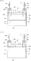
- the tank 3 stores the electrolyte 4 that is to be distributed to the battery cell 10 ( FIG. 1).
- FIG. 1 shows only the tank 3 for a positive electrode.
- a tank for a negative electrode is not shown in FIG. 1 .
- the configuration of the tank for a negative electrode may be the same as that of the tank 3 for a positive electrode.
- the size of the tank 3 can be selected as appropriate according to battery capacity.
- the shape of the tank 3 may be cuboid as in this example, or round columnar.
- the tank 3 has a top plate 33, a bottom plate 34, side plates 35, and a partition portion 36, which will be described later.
- the materials of the top plate 33, the bottom plate 34, and the side plates 35 include resin and rubber that do not react with the electrolyte 4 and have high resistance to the electrolyte 4.
- the resin include polyvinyl chloride (PVC), polypropylene (PP), polyethylene (PE), and polytetrafluoroethylene (PTFE).
- the top plate 33, the bottom plate 34, and the side plates 35 may be composed of a plate provided with a steel plate-shaped member and a coating layer covering the portion of the plate-shaped member that comes into contact with the electrolyte 4.
- the thickness of the top plate 33, the bottom plate 34, and the side plates 35 may be 5 mm or more and 50 mm or less, for example, and 10 mm or more and 40 mm or less, and in particular, 15 mm or more and 30 mm or less, for example. If each plate is composed of resin or rubber, the thickness thereof refers to the thickness of the resin or rubber, and if each plate is provided with a plate-shaped member and a coating layer, the thickness thereof refers to the total thickness of the plate-shaped member and the coating layer.
- the partition portion 36 partitions the space inside the tank 3 into the first space 31 and the second space 32.
- Examples of the material of the partition portion 36 include flexible materials that do not react with the electrolyte 4 and have high resistance to the electrolyte 4.
- the partition portion 36 composed of a flexible material refers to a member satisfying at least one of being flexible, being able to warp, not cracking when it is bent, and stretching to some extent. That is, the partition portion 36 has a property of deforming such that the volume of either the first space 31 or the second space 32 increases and the volume of the other one decreases when there are changes in the amount of the electrolyte 4 in the first space 31 and the second space 32.
- Specific examples of the material of the partition portion 36 include above-described resin and rubber.
- the partition portion 36 is composed of one flexible sheet member in this embodiment.
- the sheet member has a first surface, a second surface, and a third surface. The first surface and the second surface oppose each other. The third surface links the first surface and the second surface together
- the partition portion 36 has a thickness of 0.006 mm or more and 0.2 mm or less, for example. If the partition portion 36 is composed of a sheet member as in this embodiment, the thickness of the partition portion 36 refers to the length between the first surface and the second surface of the sheet member. If the thickness of the partition portion 36 is 0.2 mm or less, the partition portion 36 is not excessively thick, and thus has good properties described above. That is, the partition portion 36 can stretch and deform due to an increase or a decrease in the amount of the electrolyte 4 in the first space 31 and the second space 32. If the thickness of the partition portion 36 is 0.15 mm or less, the partition portion 36 has better properties described above.
- the thickness of the partition portion 36 is 0.006 mm or more, the partition portion 36 is not excessively thin, and the partition portion 36 is unlikely to tear even if it is stretched and deformed due to an increase or a decrease in the amount of the electrolyte 4 in the first space 31 and the second space 32. If the partition portion 36 has a thickness of 0.03 mm or more, the partition portion 36 is unlikely to tear. The thickness of the partition portion 36 is also 0.03 mm or more and 0.13 mm or less, and in particular, 0.06 mm or more and 0.1 mm or less.
- the partition portion 36 has an outer region 361 and an inner region 362, which will be described later in detail.
- the outer region 361 is provided over the entire peripheral edge of the partition portion 36. That is, the outer region 361 is provided over the entire peripheral edge of the first surface and the entire peripheral edge of the second surface of the sheet member.
- the outer region 361, that is, the entire peripheral edge of the first surface and the entire peripheral edge of the second surface, is a region with a certain width.
- the inner region 362 is surrounded by the outer region 361. That is, the inner region 362 is surrounded by the outer region 361 on the first surface of the sheet member, and is surrounded by the outer region 361 of the second surface of the sheet member.
- the outer region 361 fixes the partition portion 36 to the inner surface of the tank 3. Specifically, a region of the outer region 361 that comes into contact with the electrolyte 4 is fixed to the inner surface of the tank 3. Of course, the outer region 361 may be fixed to the inner surface of the tank 3 over its entire periphery. There is no particular limitation on a method for fixing the outer region 361 to the tank 3 as long as the outer region 361 can be substantially liquid-tightly fixed to the inner surface of the tank 3.
- substantially liquid-tightly fixing refers to allowing movement of a small amount of the electrolyte 4 from one of the first space 31 and the second space 32 to the other space via the outer region 361 to an extent that the state of charge of the electrolyte 4 is not affected.
- the amount of the electrolyte 4 that moves is preferably as small as possible, and preferably none moves at all.
- the partition portion 36 can substantially seal off the first space 31 and the second space 32 from each other, and preferably completely seal them off from each other. Therefore, the partition portion 36 can prevent the electrolyte 4 in the first space 31 and the electrolyte 4 in the second space 32 from mixing with each other.
- the outer region 361 is substantially liquid-tightly fixed to the inner surface of the tank 3 over its entire periphery. Examples of a method for fixing the outer region 361 include welding, fusion, and adhesion using an adhesive.
- the fixed location of the outer region 361 is a position where the volume of the first space 31 and the volume of the second space 32 are the same as each other.
- the fixed location of the outer region 361 is the top plate 33 in this example ( FIG. 4 ). Specifically, the outer region 361 is fixed to a region on the peripheral edge side of the top plate 33 of the tank 3 over its entire periphery.
- the outer region 361 is fixed to the top plate 33, the workability of manufacturing the tank 3 having the partition portion 36 is improved. One reason for this is that it is sufficient that the outer region 361 is fixed only to the top plate 33. Also, the outer region 361 can be fixed to the top plate 33 in a state in which the top plate 33 is detached from the side plates 35. The partition portion 36 is suspended from the top plate 33 because the outer region 361 is fixed to the top plate 33. Also, the first space 31 and the second space 32 are formed in an inward space and an outward space inside the tank 3.
- the inner region 362 allows change in the volumes of the first space 31 and the second space 32 along with an increase or a decrease in the amount of the electrolyte 4 in the first space 31 and the second space 32 ( FIG. 1 ). Specifically, the inner region 362 allows an increase in the volume of either the first space 31 or the second space 32 and a reduction in the volume of the other one. Because the partition portion 36 is composed of a flexible material, the inner region 362 is biased toward the first space 31 or the second space 32 or stretches toward the first space 31 or the second space 32. Therefore, the inner region 362 can change the volumes of the first space 31 and the second space 32.
- the distribution mechanism 5 distributes the electrolyte 4 to the battery cell 10.
- the distribution mechanism 5 has a distribution passage through which the electrolyte 4 is distributed between the first space 31 and the second space 32 via the battery cell 10.
- the distribution mechanism 5 in this embodiment has a first supply passage 51s, a second supply passage 52s, a supply-side connection passage 53s, a supply-side switching valve 54s, a first discharge passage 51d, a second discharge passage 52d, a discharge-side connection passage 53d, a discharge-side switching valve 54d, and a pump 55.
- FIG. 1 shows only the distribution mechanism 5 for the positive electrode.
- the distribution mechanism for the negative electrode is not shown in FIG. 1 .
- the configuration of the distribution mechanism for the negative electrode may be the same as that of the distribution mechanism 5 for the positive electrode.
- the first supply passage 51s supplies the electrolyte 4 in the first space 31 of the tank 3 to the battery cell 10.
- the upstream side of the first supply passage 51s is open in the first space 31. If the electrolyte 4 is stored in the first space 31, the upstream side of the first supply passage 51s is open in the electrolyte 4 ( FIG. 1 ).
- the downstream side of the first supply passage 51s is connected to the supply-side connection passage 53s.
- the second supply passage 52s supplies the electrolyte 4 in the second space 32 of the tank 3 to the battery cell 10.
- the upstream side of the second supply passage 52s is open in the second space 32. If the electrolyte 4 is stored in the second space 32, the upstream side of the second supply passage 52s is open in the electrolyte 4 ( FIGS. 2 and 3 ).
- the downstream side of the second supply passage 52s is connected to the supply-side connection passage 53s.
- the supply-side connection passage 53s connects the downstream sides of the first supply passage 51s and the second supply passage 52s to the battery cell 10.
- the electrolyte 4 that flows through the first supply passage 51s or the second supply passage 52s is supplied to the battery cell 10 through the supply-side connection passage 53s.
- the supply-side switching valve 54s opens one of the first supply passage 51s and the second supply passage 52s and closes the other one. That is, the supply-side switching valve 54s switches between allowing the flow of the electrolyte 4 from the first supply passage 51s to the supply-side connection passage 53s and allowing the flow of the electrolyte 4 from the second supply passage 52s to the supply-side connection passage 53s.
- An example of the location where the supply-side switching valve 54s is installed is the location where the first supply passage 51s, the second supply passage 52s, and the supply-side connection passage 53s are connected to each other.
- An example of the type of supply-side switching valve 54s is a three-way valve.
- the first discharge passage 51d discharges the electrolyte 4 that has passed through the battery cell 10 into the first space 31.
- the upstream side of the first discharge passage 51d is connected to the discharge-side connection passage 53d.
- the downstream side of the first discharge passage 51d is open in the first space 31. If the electrolyte 4 is stored in the first space 31, the downstream side of the first discharge passage 51d is open in a gas phase portion in the first space 31 ( FIG. 1 ).
- the second discharge passage 52d discharges the electrolyte 4 that has passed through the battery cell 10 into the second space 32.
- the upstream side of the second discharge passage 52d is connected to the discharge-side connection passage 53d.
- the downstream side of the second discharge passage 52d is open in the second space 32. If the electrolyte 4 is stored in the second space 32, the downstream side of the second discharge passage 52d is open in a gas phase portion in the second space 32 ( FIGS. 2 and 3 ).
- the discharge-side connection passage 53d connects the upstream sides of the first discharge passage 51d and the second discharge passage 52d to the battery cell 10.
- the electrolyte 4 discharged from the battery cell 10 flows through the discharge-side connection passage 53d and then through the first discharge passage 51d or the second discharge passage 52d.
- the discharge-side switching valve 54d opens one of the first discharge passage 51d and the second discharge passage 52d and closes the other one. That is, the discharge-side switching valve 54d switches between allowing the flow of the electrolyte 4 from the discharge-side connection passage 53d to the first discharge passage 51d and allowing the flow of the electrolyte 4 from the discharge-side connection passage 53d to the second discharge passage 52d.
- An example of the location where the discharge-side switching valve 54d is installed is the location where the discharge-side connection passage 53d, the first discharge passage 51d, and the second discharge passage 52d are connected to each other.
- an example of the type of discharge-side switching valve 54d is a three-way valve.
- the first supply passage 51s, the second supply passage 52s, the supply-side connection passage 53s, the first discharge passage 51d, the second discharge passage 52d, and the discharge-side connection passage 53d may be constituted by a resin pipe or a coated pipe, for example.
- An example of the material of the resin pipe is polyvinyl chloride.
- the coated pipe is provided with a metal pipe-shaped member, and a coating layer covering a portion of the pipe-shaped member that is in contact with the electrolyte 4.
- a stainless steel pipe may be used as the pipe-shaped member, for example.
- Examples of the material of the coating layer includes materials that do not react with the electrolyte 4 and have high resistance to the electrolyte 4. Specific examples of the material of the coating layer include materials such as resin and rubber that are similar to those of the above-described tank 3.
- the pump 55 pressure-feeds the electrolyte 4 in the first space 31 or the second space 32 to the second space 32 or the first space 31 via the battery cell 10.
- the location where the pump 55 is installed is an intermediate position of the supply-side connection passage 53s in this example.
- the pump 55 is driven during charging and discharging operations. These operations will be described when describing a controller 65 later.
- the pump 55 is stopped during a standby operation in which charging or discharging operation is not performed.
- the electrolyte 4 is not pressure-fed during this standby operation.
- the type of pump 55 may be selected as appropriate, and an example thereof is a self-priming pump.
- the supply-side switching valve 54s, the discharge-side switching valve 54d, and the pump 55 are controlled by a control mechanism 6, which will be described later.
- the control mechanism 6 controls the flow of the electrolyte 4 in the first space 31 and the flow of the electrolyte 4 in the second space 32 based on the amounts of the electrolyte in the first space 31 and the second space 32.
- the control mechanism 6 in this embodiment has a liquid amount detector and a controller 65.
- the liquid amount detector detects at least one of the amount of the electrolyte in the first space 31 and the amount of the electrolyte in the second space 32.
- the liquid amount detector has a first liquid amount detector 61 to detect the amount of the electrolyte in the first space 31 and a second liquid amount detector 62 to detect the amount of the electrolyte in the second space 32.
- the first liquid amount detector 61 and the second liquid amount detector 62 are not shown in FIGS. 2 and 3 .
- the first liquid amount detector 61 detects whether or not the amount of the electrolyte in the first space 31 is substantially zero, for example.
- the second liquid amount detector 62 detects whether or not the amount of the electrolyte in the second space 32 is substantially zero.
- first liquid amount detector 61 and second liquid amount detector 62 include switches and sensors.
- the switches include level switches such as float-type switches.
- the sensors include liquid amount sensors and liquid level sensors such as float-type, capacitance-type, optical, and ultrasonic sensors. The results of detection performed by the first liquid amount detector 61 and the second liquid amount detector 62 are sent to the controller 65.
- the controller 65 has a valve controller 651 and a pump controller 652.
- a computer or the like can be used as the controller 65, for example.
- the valve controller 651 controls operations of the supply-side switching valve 54s and the discharge-side switching valve 54d based on the results of detection performed by the liquid amount detectors.
- the valve controller 651 operates the supply-side switching valve 54s so as to open one of the first supply passage 51s and the second supply passage 52s and close the other one.
- the valve controller 651 operates the discharge-side switching valve 54d so as to open one of the first discharge passage 51d and the second discharge passage 52d and close the other one.
- the pump 55 is driven under the control of the pump controller 652 based on the results of detection performed by the liquid amount detectors.
- the pump controller 652 performs control in conjunction with the control of the valve controller 651 performed on the supply-side switching valve 54s and the discharge-side switching valve 54d.
- the pump controller 652 drives and stops the pump 55.
- the second liquid amount detector 62 detects that the amount of the electrolyte in the second space 32 is zero.
- the valve controller 651 operates the supply-side switching valve 54s so as to open the first supply passage 51s and close the second supply passage 52s based on the detection results. Also, the valve controller 651 operates the discharge-side switching valve 54d so as to open the second discharge passage 52d and close the first discharge passage 51d.
- the pump controller 652 drives the pump 55 in conjunction with the control of the valve controller 651.
- the electrolyte 4 stored in the first space 31 passes through the first supply passage 51s and the supply-side connection passage 53s in this order, and is supplied to the battery cell 10 and is charged.
- the electrolyte 4 charged in the battery cell 10 is discharged from the battery cell 10 into the second space 32, passing through the discharge-side connection passage 53d and the second discharge passage 52d in this order ( FIG. 2 ).
- the valve controller 651 and the pump controller 652 maintain the states of the supply-side switching valve 54s, the discharge-side switching valve 54d, and the pump 55 until substantially all of the electrolyte 4 in the first space 31 has been sent into the second space 32, that is, until the first liquid amount controller 61 ( FIG.
- the first liquid amount detector 61 detects that the amount of the electrolyte in the first space 31 is zero.
- the valve controller 651 performs control based on the detection results such that this procedure is the reverse of the first procedure. That is, the valve controller 651 operates the supply-side switching valve 54s so as to open the second supply passage 52s and close the first supply passage 51s. Also, the valve controller 651 operates the discharge-side switching valve 54d so as to open the first discharge passage 51d and close the second discharge passage 52d.
- the pump controller 652 drives the pump 55.
- the electrolyte 4 stored in the second space 32 passes through the second supply passage 52s and the supply-side connection passage 53s in this order, and is supplied to the battery cell 10 and is charged.
- the electrolyte 4 charged in the battery cell 10 is ejected from the battery cell 10 into the first space 31, passing through the discharge-side connection passage 53d and the first discharge passage 51d in this order ( FIG. 2 ). As shown in FIG.
- valve controller 651 and the pump controller 652 maintain the states of the supply-side switching valve 54s, the discharge-side switching valve 54d, and the pump 55 until substantially all of the electrolyte 4 in the second space 32 has been sent into the first space 31, that is, until the second liquid amount detector 62 detects that the amount of the electrolyte in the second space 32 is zero. In this manner, all of the electrolyte 4 that has been charged is stored in the first space 31.
- the controller 65 repeats the first procedure and the second procedure until the state of charge of the electrolyte 4 reaches a fully charged state. When the state of charge of the electrolyte 4 reaches the fully charged state, the controller 65 ends the first procedure and the second procedure.
- the controller 65 need not repeat the first procedure or the second procedure. In this case, the controller 65 need only perform at least one of the first procedure and the second procedure.
- the battery cell 10 is separated into a positive electrode cell and a negative electrode cell by a membrane that allows permeation of hydrogen ions.
- the membrane, the positive electrode cell, and the negative electrode cell are not shown in the drawings.
- the positive electrode cell has a built-in positive electrode.
- the positive electrolyte is distributed by the above-described distribution mechanism 5 from the above-described tank 3 into the positive electrode cell.
- the negative electrode cell has a built-in negative electrode.
- the negative electrolyte is distributed by the above-described distribution mechanism 5 from the above-described tank for the negative electrode into the negative electrode cell.
- the battery cell 10 is usually formed inside a structure called cell stack 20.
- the cell stack 20 is constituted by a layered body called a sub-stack, two end plates that sandwich the layered body from both sides, and a fastening mechanism that fastens the two end plates.
- the layered body, the end plates, and the fastening mechanism are not shown in the drawings.
- the number of sub-stacks may be one or higher.
- the sub-stack has the layered body in which a plurality of cell frames, positive electrodes, membranes, and negative electrodes are stacked on each other in the stated order, and supply/discharge plates that are arranged on the two ends of the layered body.
- Each cell frame has a bipolar plate and a frame body that surrounds an outer peripheral edge portion of the bipolar plate.
- One battery cell 10 is formed between bipolar plates of cell frames that are adjacent to each other.
- the positive electrode cells and the negative electrode cells are arranged such that the positive electrode and the negative electrode of battery cells 10 that are adjacent to each other are respectively arranged on the front and back sides of the bipolar plate that is arranged therebetween.
- the frame body of a cell frame has a liquid supply manifold and a liquid supply slit to supply the electrolyte 4 into the battery cell 10, and a liquid discharge manifold and a liquid discharge slit to discharge the electrolyte 4 to the outside of the battery cell 10.
- An annular sealing member such as an O-ring or flat packing is arranged in an annular sealing groove between frame bodies so as to suppress leakage of the electrolyte 4 from the battery cell 10.
- a known battery cell and a known cell stack can be used as the battery cell 10 and the cell stack 20.
- the RF battery 1 of this embodiment it is possible, with one tank 3 at each electrode, to prevent the electrolyte 4 discharged from the battery cell 10 to the tank 3 and the electrolyte 4 in the tank 3 from mixing with each other, without using a meandering pipe, a spiral pipe, or two tanks at each electrode as in a conventional manner.
- One reason for this is that the electrolyte 4 to be supplied to the battery cell 10 can be stored in either the first space 31 or the second space 32 due to the partition portion 36 that partitions the tank 3 being provided, and the electrolyte 4 discharged from the battery cell 10 can be stored in the other space.
- Another reason is that it is possible to discharge the electrolyte 4 stored in either the first space 31 or the second space 32 to the other space through the battery cell 10 because the supply-side switching valve 54s and the discharge-side switching valve 54d are provided. Another reason is that, because the valve controller 651 is provided, the flow of the electrolyte 4 can be switched after substantially all of the electrolyte 4 stored in either the first space 31 or the second space 32 has been distributed to the other space through the battery cell 10.
- the RF battery 1 of this embodiment does not lead to a reduction in the battery capacity, an increase in pressure loss, or an increase in installation area. This is because it is not necessary to use a meandering pipe, a spiral pipe, or two tanks at each electrode as in a conventional manner as described above. Furthermore, this is because the partition portion 36 that partitions the tank 3 is composed of a flexible material, and the volumes of the first space 31 and the second space 32 can change due to the inner region 362, and therefore the tank 3 with a large volume need not be used.
- Embodiment 1 the first space 31 and the second space 32 are provided in an inward space and an outward space inside the tank 3 due to the partition portion 36.
- Embodiment 2 will be described with reference to FIGS. 5 to 7 in which the locations where the first space 31 and the second space 32 are formed are different from those in the RF battery 1 of Embodiment 1. That is, the RF battery 1 of Embodiment 2 is different from the RF battery 1 of Embodiment 1 with regard to the location where the outer region 361 is fixed.
- the following mainly describes the difference from Embodiment 1. Configurations that are the same as those of Embodiment 1 will not be described. The same applies to Embodiment 3, which will be described later. Note that the electrolyte is not shown in FIGS. 5 to 7 for convenience of description.
- the outer region 361 may be fixed to a top plate 33, side plates 35, and a bottom plate 34 such that a first space 31 and a second space 32 are provided on the left side and the right side inside the tank 3.
- the outer region 361 may be fixed to the side plates 35 over the entire periphery thereof such that the first space 31 and the second space 32 are provided on the upper side and the lower side inside the tank 3.
- the outer region 361 may be fixed to a corner portion between the top plate 33 and one side plate 35, the side plates 35, and a corner portion between the other side plate 35 and the bottom plate 34 such that the first space 31 and the second space 32 are provided at diagonal positions inside the tank 3.
- the RF battery 1 of this embodiment can prevent the electrolyte 4 discharged from the battery cell 10 to the tank 3 and the electrolyte 4 present in the tank 3 from mixing with each other, without a reduction in the battery capacity, an increase in pressure loss, and an increase in the installation area.
- the above-described timing is different from that of the RF battery 1 of Embodiment 1. Specifically, one of the above-described timings comes before substantially all of the electrolyte 4 stored in one space has been distributed into the other space through the battery cell 10. That is, one of the above-described timings comes while the electrolyte 4 stored in one space is being distributed into the other space through the battery cell 10.
- a controller 65 has a presence/absence detector 653 and a calculation part 654 in addition to a valve controller 651 and a pump controller 652 that are similar to those of Embodiment 1.
- the valve controller 651 of this embodiment controls operations of a supply-side switching valve 54s and a discharge-side switching valve 54d based on the results of detection performed by the presence/absence detector 653 and the results of calculation performed by the calculation part 654.
- the valve controller 651 operates the supply-side switching valve 54s so as to open one of the first supply passage 51s and the second supply passage 52s and close the other one.
- the valve controller 651 operates the discharge-side switching valve 54d so as to open one of the first discharge passage 51d and the second discharge passage 52d and close the other one.
- the pump controller 652 drives the pump 55 in conjunction with the control of the valve controller 651.
- the presence/absence detector 653 detects whether or not a power request was made by a load 130. If the detection result indicates that the request was made, the RF battery 1 performs a discharging operation. If the detection result indicates that the request was not made, the RF battery 1 performs a charging operation. It is possible to detect the presence or absence of the power request made by the load 130 based on the operation of the AC/DC converter 100 performed by an instruction received from a load dispatching center or the like.
- the calculation part 654 calculates the state of charge (SOC) of the electrolyte 4 in the first space 31 and the state of charge (SOC) of the electrolyte 4 in the second space 32.
- the state of charge of the electrolyte 4 can be obtained using a measurement part 10m.
- the state of charge of the electrolyte 4 supplied to the battery cell 10 and the state of charge of the electrolyte 4 that has passed through the battery cell 10 are calculated using the measurement parts 10m provided on the upstream side and the downstream side of the battery cell 10.
- the upstream measurement part 10m is provided in an intermediate portion of a branched passage 56s branched from the supply-side connection passage 53s.
- the electrolyte 4 that has passed through the upstream measurement part 10m is returned to the supply-side connection passage 53s and is sent to the battery cell 10.
- the downstream measurement part 10m is provided in an intermediate portion of a branched passage 56d branched from the discharge-side connection passage 53d.
- FIG. 8 shows a configuration in which the positive electrolyte is supplied to the two measurement parts 10m.
- the same measurement parts are also provided on the upstream side and the downstream side of the battery cell 10 in the distribution mechanism that distributes the negative electrolyte.
- the measurement parts in the distribution mechanism for the negative electrolyte are not shown in the drawings.
- Standard electrodes 10r with known potentials are respectively connected to the upstream measurement part 10m and the downstream measurement part 10m.
- a saturated KCl silver-silver chloride electrode (Ag/AgCl/saturated KCl solution) can be used as the standard electrode 10r, for example.
- Voltage measurement parts 10v to measure the absolute potential of an electrolyte are respectively provided between the upstream measurement part 10m and the standard electrode 10r and between the downstream measurement part 10m and the standard electrode 10r.
- a voltmeter can be used as the voltage measurement part 10v.
- the results of measurement performed by the voltage measurement parts 10v are sent to the calculation part 654 and are used to calculate the state of charge of the electrolyte 4. This calculation is performed by a computer.
- the states of charge of the electrolyte 4 in the first space 31 and the second space 32 can be obtained based on the state of calculated charge of the electrolyte 4 and the distribution path of the electrolyte 4 formed by controlling the supply-side switching valve 54s and the discharge-side switching valve 54d.
- the state of charge of the electrolyte 4 may be obtained as a result of respectively providing monitor cells having the same configuration as that of the battery cell 10 on the upstream side and the downstream side of the battery cell 10 and measuring the open-circuit potentials of the monitor cells, instead of using the measurement parts 10m and the standard electrodes 10r.
- the measured open-circuit potentials are sent to the calculation part 654 and are used to calculate the state of charge of the electrolyte 4.
- the calculation part 654 calculates the state of charge of the electrolyte 4 in the first space 31 and the state of charge of the electrolyte 4 in the second space 32.
- the valve controller 651 controls the operations of the supply-side switching valve 54s and the discharge-side switching valve 54d such that out of the electrolyte 4 in the first space 31 and the second space 32, the one that has the higher state of charge is distributed to the battery cell 10. For example, if the electrolyte 4 in the first space 31 has a higher state of charge, the valve controller 651 operates the supply-side switching valve 54s so as to open the first supply passage 51s and close the second supply passage 52s.
- valve controller 651 operates the discharge-side switching valve 54d so as to open the second discharge passage 52d and close the first discharge passage 51d.
- the pump controller 652 temporarily stops the pump 55 before the valve controller 651 starts the above-described control, and drives the pump 55 after the valve controller 651 has completed the above-described control. Due to this control, the electrolyte 4 in the first space 31 passes through the first supply passage 51s and the supply-side connection passage 53s in this order, and is supplied to the battery cell 10 and is discharged.
- the electrolyte 4 that has been discharged in the battery cell 10 and whose state of charge has decreased passes through the discharge-side connection passage 53d and the second discharge passage 52d in this order and is discharged into the second space 32.
- the first liquid amount detector 61 detects that the amount of the electrolyte in the first space 31 is zero. Then, the valve controller 651 performs control such that this procedure is the reverse of the above-described procedure. That is, the valve controller 651 operates the supply-side switching valve 54s so as to open the second supply passage 52s and close the first supply passage 51s. Also, the valve controller 651 operates the discharge-side switching valve 54d so as to open the first discharge passage 51d and close the second discharge passage 52d.
- the pump controller 652 temporarily stops the pump 55 before the valve controller 651 starts the above-described control, and drives the pump 55 after the valve controller 651 has completed the above-described control. Due to this control, the electrolyte 4 stored in the second space 32 passes through the second supply passage 52s and the supply-side connection passage 53s in this order, and is supplied to the battery cell 10 and is discharged. The electrolyte 4 discharged in the battery cell 10 is discharged from the battery cell 10 into the first space 31, passing through the discharge-side connection passage 53d and the first discharge passage 51d in this order.
- the electrolyte 4 is charged by distributing the electrolyte 4 in the second space 32 with a low state of charge to the battery cell 10.
- the calculation part 654 calculates the state of charge of the electrolyte 4 in the first space 31 and the state of charge of the electrolyte 4 in the second space 32.
- the valve controller 651 controls the operations of the supply-side switching valve 54s and the discharge-side switching valve 54d such that out of the electrolyte 4 in the first space 31 and the second space 32, the one that has the lower state of charge is distributed to the battery cell 10. For example, if the electrolyte 4 in the second space 32 has a lower state of charge, the valve controller 651 operates the supply-side switching valve 54s so as to open the second supply passage 52s and close the first supply passage 51s.
- valve controller 651 operates the discharge-side switching valve 54d so as to open the first discharge passage 51d and close the second discharge passage 52d.
- the pump controller 652 temporarily stops the pump 55 before the valve controller 651 starts the above-described control, and drives the pump 55 after the valve controller 651 has completed the above-described control. Due to this control, the electrolyte 4 stored in the second space 32 passes through the second supply passage 52s and the supply-side connection passage 53s in this order, and is supplied to the battery cell 10 and is charged.
- the electrolyte 4 charged in the battery cell 10 passes through the discharge-side connection passage 53d and the first discharge passage 51d in this order, and is discharged into the first space 31.
- the second liquid amount detector 62 detects that the amount of the electrolyte in the second space 32 is zero. Then, the valve controller 651 and the pump controller 652 perform control such that this procedure is the reverse of the above-described procedure. That is, the valve controller 651 operates the supply-side switching valve 54s so as to open the first supply passage 51s and close the second supply passage 52s. Also, the valve controller 651 operates the discharge-side switching valve 54d so as to open the second discharge passage 52d and close the first discharge passage 51d.
- the pump controller 652 temporarily stops the pump 55 before the valve controller 651 starts the above-described control, and drives the pump 55 after the valve controller 651 has completed the above-described control. Due to this control, the electrolyte 4 stored in the first space 31 passes through the first supply passage 51s and the supply-side connection passage 53s in this order, and is supplied to the battery cell 10 and is charged. The electrolyte 4 charged in the battery cell 10 is discharged from the battery cell 10 into the second space 32, passing through the discharge-side connection passage 53d and the second discharge passage 52d in this order.
- the RF battery 1 of this embodiment it is possible to switch the flow of the electrolyte 4 before substantially all of the electrolyte 4 stored in either the first space 31 or the second space 32 has been distributed into the other space through the battery cell 10. Therefore, even if the load 130 has made a power request during charge, for example, it is possible to immediately handle the power request made by the load 130.
Landscapes
- Life Sciences & Earth Sciences (AREA)
- Engineering & Computer Science (AREA)
- Manufacturing & Machinery (AREA)
- Sustainable Development (AREA)
- Sustainable Energy (AREA)
- Chemical & Material Sciences (AREA)
- Chemical Kinetics & Catalysis (AREA)
- Electrochemistry (AREA)
- General Chemical & Material Sciences (AREA)
- Fuel Cell (AREA)
- Inert Electrodes (AREA)
Abstract
Description
- The present disclosure relates to a redox flow battery.
- The present application claims the benefit of priority based on
Japanese Patent Application No. 2019-035027 filed on February 27, 2019 - A redox flow type secondary battery disclosed in
Patent Document 1 has a configuration in which one long meandering pipe or spiral pipe for storing an electrolyte is used, or a configuration in which two positive electrolyte tanks and two negative electrolyte tanks for storing electrolyte is used. The meandering pipe and the spiral pipe have a length such that an electrolyte in each pipe that is supplied to a battery cell and an electrolyte discharged from the battery cell to the pipe do not mix with each other. - On the other hand, if two positive electrolyte tanks and two negative electrolyte tanks are used, a positive electrolyte is supplied from one positive electrolyte tank to the battery cell, and is discharged from the battery cell to the other positive electrolyte tank. If all of the positive electrolyte in one positive electrolyte tank is to be distributed to the other positive electrolyte tank, a pump is driven in the reverse direction such that the positive electrolyte is supplied from the other positive electrolyte tank to the battery cell, and is discharged from the battery cell to the one positive electrolyte tank. The use of two positive electrolyte tanks and two negative electrolyte tanks in this manner prevents an electrolyte discharged from a battery cell from mixing with an electrolyte supplied to the battery cell.
- Patent Document 1:
JP H2-27666A - A redox flow battery according to an aspect of the present disclosure is a redox flow battery including:
- a tank configured to store an electrolyte; and
- a distribution mechanism to distribute the electrolyte to a battery cell;
- in which the tank has a partition portion partitioning a space inside the tank into a first space and a second space,
- the distribution mechanism has a distribution passage through which the electrolyte is distributed between the first space and the second space via the battery cell, and
- the partition portion is composed of a flexible material.
-
-
FIG. 1 is a configuration diagram showing an overview of a redox flow battery according toEmbodiment 1. -
FIG. 2 is a configuration diagram illustrating a path through which an electrolyte of the redox flow battery according toEmbodiment 1 is distributed. -
FIG. 3 is a configuration diagram illustrating the path through which the electrolyte of the redox flow battery according toEmbodiment 1 is distributed. -
FIG. 4 is a top view of a tank provided in the redox flow battery according toEmbodiment 1. -
FIG. 5 is a configuration diagram showing an overview of examples of a tank and a distribution mechanism provided in a redox flow battery according to Embodiment 2. -
FIG. 6 is a configuration diagram showing an overview of other examples of the tank and the distribution mechanism provided in the redox flow battery according to Embodiment 2. -
FIG. 7 is a configuration diagram showing an overview of other examples of the tank and the distribution mechanism provided in the redox flow battery according to Embodiment 2. -
FIG. 8 is a configuration diagram showing an overview of a redox flow battery according toEmbodiment 3. - The battery capacity and the amount of electrolyte of the redox flow battery are in a proportional relationship. That is, if a redox flow battery with a large battery capacity is to be constructed, the amount of electrolyte increases. If the amount of electrolyte increases, the length of the meandering pipe or the spiral pipe increases. As a result, pressure loss increases. If the amount of electrolyte is reduced and the length of the meandering pipe or the spiral pipe is reduced, an increase in pressure loss is suppressed. However, the battery capacity of the redox flow battery is reduced. Also, if two tanks for the positive electrolyte and two tanks for the negative electrolyte are used as described above, even if the amount of electrolyte is large, the increase in pressure loss is lower than in the case where a spiral pipe or the like is used. However, the area required for tank installation increases.
- In view of this, an object of the present disclosure is to provide a redox flow battery that can prevent an electrolyte discharged from a battery cell to a tank and an electrolyte present in the tank from mixing with each other, without a reduction in the battery capacity, an increase in pressure loss, and an increase in the installation area.
- A redox flow battery according to the present disclosure can prevent an electrolyte discharged from a battery cell to a tank and an electrolyte present in the tank from mixing with each other, without a reduction in the battery capacity, an increase in pressure loss, and an increase in the installation area.
- First, embodiments of the present disclosure will be described below.
- (1) A redox flow battery according to an aspect of the present disclosure is a redox flow battery including:
- a tank configured to store an electrolyte; and
- a distribution mechanism to distribute the electrolyte to a battery cell;
- in which the tank has a partition portion partitioning a space inside the tank into a first space and a second space,
- the distribution mechanism has a distribution passage through which the electrolyte is distributed between the first space and the second space via the battery cell, and
- the partition portion is composed of a flexible material.
- With the above-described configuration, it is possible, with one tank at each electrode, to prevent an electrolyte discharged from a battery cell to the tank and an electrolyte present in the tank from mixing with each other, without using a meandering pipe, a spiral pipe, or two tanks at each electrode as in a conventional manner. One reason for this is that due to the partition portion that partitions the tank being provided, the electrolyte to be supplied to the battery cell can be stored in one of the first space and the second space, and the electrolyte discharged from the battery cell can be stored in the other space. Averaging of the states of charge of the electrolyte is suppressed due to the electrolyte being prevented from mixing with each other. Therefore, the above-described configuration can suppress a continuous increase in cell resistance. Thus, the above-described configuration can improve battery efficiency, that is, the charge and discharge efficiency.
- Also, the above-described configuration does not lead to a reduction in battery capacity, an increase in pressure loss, or an increase in installation area. One reason for this is that it is not necessary to use a meandering pipe, a spiral pipe, or two tanks at each electrode as in a conventional manner as described above. Another reason is that the partition portion that partitions the tank is composed of a flexible material, and thus a tank with a large volume need not be used.
- (2) As an embodiment of the redox flow battery,
- the partition portion has an outer region provided at the entire peripheral edge of the partition portion and an inner region surrounded by the outer region,
- a region of the outer region that comes into contact with the electrolyte is substantially liquid-tightly fixed to an inner surface of the tank, and
- the inner region allows change in volumes of spaces such that the volume of one of the first space and the second space increases and the volume of the other space decreases along with an increase or a decrease in the amount of the electrolyte in the first space and the second space.
- With the above-described configuration, because the outer region has a region that is substantially liquid-tightly fixed to the inner surface of the tank, it is possible, with one tank at each electrode, to further prevent the electrolyte discharged from the battery cell to the tank and an electrolyte present in the tank from mixing with each other. Also, the above-described configuration does not lead to a reduction in battery capacity, an increase in pressure loss, or an increase in installation area. One reason for this is that the volumes of the first space and the second space can change due to the inner region.
- (3) As an embodiment of the redox flow battery,
the distribution mechanism includes: - a first supply passage to supply the electrolyte in the first space to the battery cell;
- a second supply passage to supply the electrolyte in the second space to the battery cell;
- one supply-side connection passage connecting downstream sides of the first supply passage and the second supply passage to the battery cell;
- a first discharge passage to discharge the electrolyte that has passed through the battery cell into the first space;
- a second discharge passage to discharge the electrolyte that has passed through the battery cell into the second space;
- one discharge-side connection passage connecting upstream sides of the first discharge passage and the second discharge passage to the battery cell;
- a supply-side switching valve that is provided at a location where the first supply passage, the second supply passage, and the supply-side connection passage are connected to each other, the supply-side switching valve being configured to switch between allowing a flow of the electrolyte from the first supply passage to the supply-side connection passage and allowing a flow of the electrolyte from the second supply passage to the supply-side connection passage; and
- a discharge-side switching valve that is provided at a location where the first discharge passage, the second discharge passage, and the discharge-side connection passage are connected to each other, the discharge-side switching valve being configured to switch between allowing a flow of the electrolyte from the discharge-side connection passage to the first discharge passage and allowing a flow of the electrolyte from the discharge-side connection passage to the second discharge passage.
- With the above-described configuration, it is possible to prevent the electrolyte discharged from the battery cell to a tank at each electrode and the electrolyte present in the tank from mixing with each other. One reason for this is that it is possible to discharge the electrolyte stored in one of the first space and the second space to the other space through the battery cell because the supply-side switching valve and the discharge-side switching valve are provided.
- (4) An embodiment of the redox flow battery having the supply-side switching valve and the discharge-side switching valve includes:
- a liquid amount detector configured to detect at least one of the amount of the electrolyte in the first space and the amount of the electrolyte in the second space; and
- a valve controller configured to control operations of the supply-side switching valve and the discharge-side switching valve based on a result of detection performed by the liquid amount detector.
- With the above-described configuration, it is possible to prevent the electrolyte discharged from the battery cell to a tank at each electrode and the electrolyte present in the tank from mixing with each other. One reason for this is that the flow of the electrolyte can be switched after substantially all of the electrolyte stored in either the first space or the second space has been distributed to the other space through the battery cell.
- (5) An embodiment of the redox flow battery having the supply-side switching valve and the discharge-side switching valve includes:
- a presence/absence detector configured to detect whether or not a power request was made by a load to which power is to be supplied from the redox flow battery;
- a calculation part configured to calculate a state of charge of the electrolyte in the first space and the state of charge of the electrolyte in the second space; and
- a valve controller configured to control operations of the supply-side switching valve and the discharge-side switching valve based on a result of detection performed by the presence/absence detector and a result of calculation performed by the calculation part.
- With the above-described configuration, it is possible to perform charging and discharging in accordance with the presence or absence of a power request made by a load. One reason for this is that the flow of the electrolyte can be switched before the distribution of substantially all of the electrolyte stored in one of the first space and the second space to the other space through the battery cell ends.
- (6) As an embodiment of the redox flow battery,
- the partition portion has an outer region provided at the entire peripheral edge of the partition portion and an inner region surrounded by the outer region,
- the outer region is fixed to a peripheral edge of a top plate of the tank, and the partition portion is suspended from the top plate of the tank, and
- the first space and the second space are provided in an inward space and an outward space inside the tank.
- With the above-described configuration, the workability of manufacturing a tank having a partition portion is improved. One reason for this is that the outer region need only be fixed to the top plate. Also, the outer region can be fixed to the top plate in a state in which the top plate is detached from the tank.
- Embodiments of the present disclosure will be described in detail below. The same reference numerals in the drawings indicate objects having the same names.
- A redox flow battery according to
Embodiment 1 will be described with referenceFIGS. 1 to 4 . The redox flow battery may be referred to as anRF battery 1 hereinafter. TheRF battery 1 is provided with atank 3 to store anelectrolyte 4, and adistribution mechanism 5 to distribute theelectrolyte 4 to abattery cell 10. One of the characteristics of theRF battery 1 is that aspecific partition portion 36 partitioning the inner portion of thetank 3 into afirst space 31 and asecond space 32 is provided. An overview of theRF battery 1 will be described below, and then constituent elements of theRF battery 1 according to this embodiment will be described in detail. - The
RF battery 1 is typically connected between apower generation portion 110 and aload 130 via an AC/DC converter 100 and aelectrical substation 120, and theRF battery 1 is charged with and stores power generated by thepower generation portion 110, and discharges and supplies the stored power to the load 130 (FIG. 1 ). The solid-line arrow extending from theelectrical substation 120 shown inFIG. 1 toward the AC/DC converter 100 indicates charging. The dashed-line arrow extending from the AC/DC converter 100 shown inFIG. 1 toward theelectrical substation 120 indicates discharging. Examples of thepower generation portion 110 include a solar photovoltaic power generation device, a wind power generation device, and other general power plants. Examples of theload 130 include electric power consumers. With theRF battery 1, theelectrolyte 4, which contains metal ions whose valence changes due to redox as active materials, is used for a positive electrolyte and a negative electrolyte. TheRF battery 1 is charged and is discharged using the difference between the redox potential of ions contained in the positive electrolyte and the redox potential of ions contained in the negative electrolyte. Examples of metal ions include vanadium ions, titanium ions, and manganese ions. Examples of the solvent of theelectrolyte 4 include an aqueous solution containing one or more acids selected from the group consisting of sulfuric acid, phosphoric acid, nitric acid, and hydrochloric acid, or an acid salt thereof. TheRF battery 1 is used for load leveling applications, applications such as instantaneous low compensation and emergency power sources, and applications for smoothing the output of natural energy such as solar photovoltaic power generation and wind power generation, which are being introduced in large quantities. - The
tank 3 stores theelectrolyte 4 that is to be distributed to the battery cell 10 (FIG. 1). FIG. 1 shows only thetank 3 for a positive electrode. A tank for a negative electrode is not shown inFIG. 1 . The configuration of the tank for a negative electrode may be the same as that of thetank 3 for a positive electrode. The size of thetank 3 can be selected as appropriate according to battery capacity. The shape of thetank 3 may be cuboid as in this example, or round columnar. - The
tank 3 has atop plate 33, abottom plate 34,side plates 35, and apartition portion 36, which will be described later. Examples of the materials of thetop plate 33, thebottom plate 34, and theside plates 35 include resin and rubber that do not react with theelectrolyte 4 and have high resistance to theelectrolyte 4. Examples of the resin include polyvinyl chloride (PVC), polypropylene (PP), polyethylene (PE), and polytetrafluoroethylene (PTFE). In addition, thetop plate 33, thebottom plate 34, and theside plates 35 may be composed of a plate provided with a steel plate-shaped member and a coating layer covering the portion of the plate-shaped member that comes into contact with theelectrolyte 4. Examples of the material of the coating layer include above-described resin and rubber. The thickness of thetop plate 33, thebottom plate 34, and theside plates 35 may be 5 mm or more and 50 mm or less, for example, and 10 mm or more and 40 mm or less, and in particular, 15 mm or more and 30 mm or less, for example. If each plate is composed of resin or rubber, the thickness thereof refers to the thickness of the resin or rubber, and if each plate is provided with a plate-shaped member and a coating layer, the thickness thereof refers to the total thickness of the plate-shaped member and the coating layer. - The
partition portion 36 partitions the space inside thetank 3 into thefirst space 31 and thesecond space 32. Examples of the material of thepartition portion 36 include flexible materials that do not react with theelectrolyte 4 and have high resistance to theelectrolyte 4. Thepartition portion 36 composed of a flexible material refers to a member satisfying at least one of being flexible, being able to warp, not cracking when it is bent, and stretching to some extent. That is, thepartition portion 36 has a property of deforming such that the volume of either thefirst space 31 or thesecond space 32 increases and the volume of the other one decreases when there are changes in the amount of theelectrolyte 4 in thefirst space 31 and thesecond space 32. Specific examples of the material of thepartition portion 36 include above-described resin and rubber. Thepartition portion 36 is composed of one flexible sheet member in this embodiment. The sheet member has a first surface, a second surface, and a third surface. The first surface and the second surface oppose each other. The third surface links the first surface and the second surface together. - The
partition portion 36 has a thickness of 0.006 mm or more and 0.2 mm or less, for example. If thepartition portion 36 is composed of a sheet member as in this embodiment, the thickness of thepartition portion 36 refers to the length between the first surface and the second surface of the sheet member. If the thickness of thepartition portion 36 is 0.2 mm or less, thepartition portion 36 is not excessively thick, and thus has good properties described above. That is, thepartition portion 36 can stretch and deform due to an increase or a decrease in the amount of theelectrolyte 4 in thefirst space 31 and thesecond space 32. If the thickness of thepartition portion 36 is 0.15 mm or less, thepartition portion 36 has better properties described above. If the thickness of thepartition portion 36 is 0.006 mm or more, thepartition portion 36 is not excessively thin, and thepartition portion 36 is unlikely to tear even if it is stretched and deformed due to an increase or a decrease in the amount of theelectrolyte 4 in thefirst space 31 and thesecond space 32. If thepartition portion 36 has a thickness of 0.03 mm or more, thepartition portion 36 is unlikely to tear. The thickness of thepartition portion 36 is also 0.03 mm or more and 0.13 mm or less, and in particular, 0.06 mm or more and 0.1 mm or less. - The
partition portion 36 has anouter region 361 and aninner region 362, which will be described later in detail. Theouter region 361 is provided over the entire peripheral edge of thepartition portion 36. That is, theouter region 361 is provided over the entire peripheral edge of the first surface and the entire peripheral edge of the second surface of the sheet member. Theouter region 361, that is, the entire peripheral edge of the first surface and the entire peripheral edge of the second surface, is a region with a certain width. Theinner region 362 is surrounded by theouter region 361. That is, theinner region 362 is surrounded by theouter region 361 on the first surface of the sheet member, and is surrounded by theouter region 361 of the second surface of the sheet member. - The
outer region 361 fixes thepartition portion 36 to the inner surface of thetank 3. Specifically, a region of theouter region 361 that comes into contact with theelectrolyte 4 is fixed to the inner surface of thetank 3. Of course, theouter region 361 may be fixed to the inner surface of thetank 3 over its entire periphery. There is no particular limitation on a method for fixing theouter region 361 to thetank 3 as long as theouter region 361 can be substantially liquid-tightly fixed to the inner surface of thetank 3. "Substantially liquid-tightly fixing" refers to allowing movement of a small amount of theelectrolyte 4 from one of thefirst space 31 and thesecond space 32 to the other space via theouter region 361 to an extent that the state of charge of theelectrolyte 4 is not affected. The amount of theelectrolyte 4 that moves is preferably as small as possible, and preferably none moves at all. As a result of theouter region 361 being substantially liquid-tightly fixed, thepartition portion 36 can substantially seal off thefirst space 31 and thesecond space 32 from each other, and preferably completely seal them off from each other. Therefore, thepartition portion 36 can prevent theelectrolyte 4 in thefirst space 31 and theelectrolyte 4 in thesecond space 32 from mixing with each other. In this embodiment, theouter region 361 is substantially liquid-tightly fixed to the inner surface of thetank 3 over its entire periphery. Examples of a method for fixing theouter region 361 include welding, fusion, and adhesion using an adhesive. - There is no particular limitation on the fixed location of the
outer region 361 as long as thefirst space 31 and thesecond space 32 can be formed such that the same amount of theelectrolyte 4 can be stored in thefirst space 31 and thesecond space 32, and the fixed location of theouter region 361 can be selected as appropriate. It is preferable that the fixed location of theouter region 361 is a position where the volume of thefirst space 31 and the volume of thesecond space 32 are the same as each other. The fixed location of theouter region 361 is thetop plate 33 in this example (FIG. 4 ). Specifically, theouter region 361 is fixed to a region on the peripheral edge side of thetop plate 33 of thetank 3 over its entire periphery. Because theouter region 361 is fixed to thetop plate 33, the workability of manufacturing thetank 3 having thepartition portion 36 is improved. One reason for this is that it is sufficient that theouter region 361 is fixed only to thetop plate 33. Also, theouter region 361 can be fixed to thetop plate 33 in a state in which thetop plate 33 is detached from theside plates 35. Thepartition portion 36 is suspended from thetop plate 33 because theouter region 361 is fixed to thetop plate 33. Also, thefirst space 31 and thesecond space 32 are formed in an inward space and an outward space inside thetank 3. - It is preferable that the
inner region 362 allows change in the volumes of thefirst space 31 and thesecond space 32 along with an increase or a decrease in the amount of theelectrolyte 4 in thefirst space 31 and the second space 32 (FIG. 1 ). Specifically, theinner region 362 allows an increase in the volume of either thefirst space 31 or thesecond space 32 and a reduction in the volume of the other one. Because thepartition portion 36 is composed of a flexible material, theinner region 362 is biased toward thefirst space 31 or thesecond space 32 or stretches toward thefirst space 31 or thesecond space 32. Therefore, theinner region 362 can change the volumes of thefirst space 31 and thesecond space 32. - The
distribution mechanism 5 distributes theelectrolyte 4 to thebattery cell 10. Thedistribution mechanism 5 has a distribution passage through which theelectrolyte 4 is distributed between thefirst space 31 and thesecond space 32 via thebattery cell 10. Thedistribution mechanism 5 in this embodiment has afirst supply passage 51s, asecond supply passage 52s, a supply-side connection passage 53s, a supply-side switching valve 54s, afirst discharge passage 51d, asecond discharge passage 52d, a discharge-side connection passage 53d, a discharge-side switching valve 54d, and apump 55.FIG. 1 shows only thedistribution mechanism 5 for the positive electrode. The distribution mechanism for the negative electrode is not shown inFIG. 1 . The configuration of the distribution mechanism for the negative electrode may be the same as that of thedistribution mechanism 5 for the positive electrode. - The
first supply passage 51s supplies theelectrolyte 4 in thefirst space 31 of thetank 3 to thebattery cell 10. The upstream side of thefirst supply passage 51s is open in thefirst space 31. If theelectrolyte 4 is stored in thefirst space 31, the upstream side of thefirst supply passage 51s is open in the electrolyte 4 (FIG. 1 ). The downstream side of thefirst supply passage 51s is connected to the supply-side connection passage 53s. - The
second supply passage 52s supplies theelectrolyte 4 in thesecond space 32 of thetank 3 to thebattery cell 10. The upstream side of thesecond supply passage 52s is open in thesecond space 32. If theelectrolyte 4 is stored in thesecond space 32, the upstream side of thesecond supply passage 52s is open in the electrolyte 4 (FIGS. 2 and 3 ). The downstream side of thesecond supply passage 52s is connected to the supply-side connection passage 53s. - The supply-
side connection passage 53s connects the downstream sides of thefirst supply passage 51s and thesecond supply passage 52s to thebattery cell 10. Theelectrolyte 4 that flows through thefirst supply passage 51s or thesecond supply passage 52s is supplied to thebattery cell 10 through the supply-side connection passage 53s. - The supply-
side switching valve 54s opens one of thefirst supply passage 51s and thesecond supply passage 52s and closes the other one. That is, the supply-side switching valve 54s switches between allowing the flow of theelectrolyte 4 from thefirst supply passage 51s to the supply-side connection passage 53s and allowing the flow of theelectrolyte 4 from thesecond supply passage 52s to the supply-side connection passage 53s. An example of the location where the supply-side switching valve 54s is installed is the location where thefirst supply passage 51s, thesecond supply passage 52s, and the supply-side connection passage 53s are connected to each other. An example of the type of supply-side switching valve 54s is a three-way valve. - The
first discharge passage 51d discharges theelectrolyte 4 that has passed through thebattery cell 10 into thefirst space 31. The upstream side of thefirst discharge passage 51d is connected to the discharge-side connection passage 53d. The downstream side of thefirst discharge passage 51d is open in thefirst space 31. If theelectrolyte 4 is stored in thefirst space 31, the downstream side of thefirst discharge passage 51d is open in a gas phase portion in the first space 31 (FIG. 1 ). - The
second discharge passage 52d discharges theelectrolyte 4 that has passed through thebattery cell 10 into thesecond space 32. The upstream side of thesecond discharge passage 52d is connected to the discharge-side connection passage 53d. The downstream side of thesecond discharge passage 52d is open in thesecond space 32. If theelectrolyte 4 is stored in thesecond space 32, the downstream side of thesecond discharge passage 52d is open in a gas phase portion in the second space 32 (FIGS. 2 and 3 ). - The discharge-
side connection passage 53d connects the upstream sides of thefirst discharge passage 51d and thesecond discharge passage 52d to thebattery cell 10. Theelectrolyte 4 discharged from thebattery cell 10 flows through the discharge-side connection passage 53d and then through thefirst discharge passage 51d or thesecond discharge passage 52d. - The discharge-
side switching valve 54d opens one of thefirst discharge passage 51d and thesecond discharge passage 52d and closes the other one. That is, the discharge-side switching valve 54d switches between allowing the flow of theelectrolyte 4 from the discharge-side connection passage 53d to thefirst discharge passage 51d and allowing the flow of theelectrolyte 4 from the discharge-side connection passage 53d to thesecond discharge passage 52d. An example of the location where the discharge-side switching valve 54d is installed is the location where the discharge-side connection passage 53d, thefirst discharge passage 51d, and thesecond discharge passage 52d are connected to each other. Similarly to the supply-side switching valve 54s, an example of the type of discharge-side switching valve 54d is a three-way valve. - The
first supply passage 51s, thesecond supply passage 52s, the supply-side connection passage 53s, thefirst discharge passage 51d, thesecond discharge passage 52d, and the discharge-side connection passage 53d may be constituted by a resin pipe or a coated pipe, for example. An example of the material of the resin pipe is polyvinyl chloride. The coated pipe is provided with a metal pipe-shaped member, and a coating layer covering a portion of the pipe-shaped member that is in contact with theelectrolyte 4. A stainless steel pipe may be used as the pipe-shaped member, for example. Examples of the material of the coating layer includes materials that do not react with theelectrolyte 4 and have high resistance to theelectrolyte 4. Specific examples of the material of the coating layer include materials such as resin and rubber that are similar to those of the above-describedtank 3. - The
pump 55 pressure-feeds theelectrolyte 4 in thefirst space 31 or thesecond space 32 to thesecond space 32 or thefirst space 31 via thebattery cell 10. The location where thepump 55 is installed is an intermediate position of the supply-side connection passage 53s in this example. Thepump 55 is driven during charging and discharging operations. These operations will be described when describing acontroller 65 later. Thepump 55 is stopped during a standby operation in which charging or discharging operation is not performed. Theelectrolyte 4 is not pressure-fed during this standby operation. The type ofpump 55 may be selected as appropriate, and an example thereof is a self-priming pump. - The supply-
side switching valve 54s, the discharge-side switching valve 54d, and thepump 55 are controlled by acontrol mechanism 6, which will be described later. - The
control mechanism 6 controls the flow of theelectrolyte 4 in thefirst space 31 and the flow of theelectrolyte 4 in thesecond space 32 based on the amounts of the electrolyte in thefirst space 31 and thesecond space 32. Thecontrol mechanism 6 in this embodiment has a liquid amount detector and acontroller 65. - The liquid amount detector detects at least one of the amount of the electrolyte in the
first space 31 and the amount of the electrolyte in thesecond space 32. In this embodiment, the liquid amount detector has a firstliquid amount detector 61 to detect the amount of the electrolyte in thefirst space 31 and a secondliquid amount detector 62 to detect the amount of the electrolyte in thesecond space 32. For convenience of description, the firstliquid amount detector 61 and the secondliquid amount detector 62 are not shown inFIGS. 2 and 3 . The firstliquid amount detector 61 detects whether or not the amount of the electrolyte in thefirst space 31 is substantially zero, for example. Similarly, the secondliquid amount detector 62 detects whether or not the amount of the electrolyte in thesecond space 32 is substantially zero. - Examples of types of first
liquid amount detector 61 and secondliquid amount detector 62 include switches and sensors. Examples of the switches include level switches such as float-type switches. Examples of the sensors include liquid amount sensors and liquid level sensors such as float-type, capacitance-type, optical, and ultrasonic sensors. The results of detection performed by the firstliquid amount detector 61 and the secondliquid amount detector 62 are sent to thecontroller 65. - The
controller 65 has avalve controller 651 and apump controller 652. A computer or the like can be used as thecontroller 65, for example. - The
valve controller 651 controls operations of the supply-side switching valve 54s and the discharge-side switching valve 54d based on the results of detection performed by the liquid amount detectors. Thevalve controller 651 operates the supply-side switching valve 54s so as to open one of thefirst supply passage 51s and thesecond supply passage 52s and close the other one. Also, thevalve controller 651 operates the discharge-side switching valve 54d so as to open one of thefirst discharge passage 51d and thesecond discharge passage 52d and close the other one. - The
pump 55 is driven under the control of thepump controller 652 based on the results of detection performed by the liquid amount detectors. In other words, thepump controller 652 performs control in conjunction with the control of thevalve controller 651 performed on the supply-side switching valve 54s and the discharge-side switching valve 54d. Thepump controller 652 drives and stops thepump 55. - A procedure in which the flow of the
electrolyte 4 in thefirst space 31 and the flow of theelectrolyte 4 in thesecond space 32 are controlled by thecontroller 65 will be described below. A case where theelectrolyte 4 is charged will be described here as an example. - As shown in
FIG. 1 , if substantially all of theelectrolyte 4 is stored in thefirst space 31 and substantially none of theelectrolyte 4 is stored in thesecond space 32, the secondliquid amount detector 62 detects that the amount of the electrolyte in thesecond space 32 is zero. Thevalve controller 651 operates the supply-side switching valve 54s so as to open thefirst supply passage 51s and close thesecond supply passage 52s based on the detection results. Also, thevalve controller 651 operates the discharge-side switching valve 54d so as to open thesecond discharge passage 52d and close thefirst discharge passage 51d. Thepump controller 652 drives thepump 55 in conjunction with the control of thevalve controller 651. Due to this control, theelectrolyte 4 stored in thefirst space 31 passes through thefirst supply passage 51s and the supply-side connection passage 53s in this order, and is supplied to thebattery cell 10 and is charged. Theelectrolyte 4 charged in thebattery cell 10 is discharged from thebattery cell 10 into thesecond space 32, passing through the discharge-side connection passage 53d and thesecond discharge passage 52d in this order (FIG. 2 ). As shown inFIG. 3 , thevalve controller 651 and thepump controller 652 maintain the states of the supply-side switching valve 54s, the discharge-side switching valve 54d, and thepump 55 until substantially all of theelectrolyte 4 in thefirst space 31 has been sent into thesecond space 32, that is, until the first liquid amount controller 61 (FIG. 1 ) detects that the amount of the electrolyte in thefirst space 31 is zero. In this manner, all of theelectrolyte 4 that has been charged is stored in thesecond space 32. When all of theelectrolyte 4 that has been charged is stored in thesecond space 32, thepump controller 652 stops thepump 55. - As shown in
FIG. 3 , if substantially all of theelectrolyte 4 is stored in thesecond space 32 and substantially none of theelectrolyte 4 is stored in thefirst space 31, the first liquid amount detector 61 (FIG. 1 ) detects that the amount of the electrolyte in thefirst space 31 is zero. Thevalve controller 651 performs control based on the detection results such that this procedure is the reverse of the first procedure. That is, thevalve controller 651 operates the supply-side switching valve 54s so as to open thesecond supply passage 52s and close thefirst supply passage 51s. Also, thevalve controller 651 operates the discharge-side switching valve 54d so as to open thefirst discharge passage 51d and close thesecond discharge passage 52d. Thepump controller 652 drives thepump 55. Due to this control, theelectrolyte 4 stored in thesecond space 32 passes through thesecond supply passage 52s and the supply-side connection passage 53s in this order, and is supplied to thebattery cell 10 and is charged. Theelectrolyte 4 charged in thebattery cell 10 is ejected from thebattery cell 10 into thefirst space 31, passing through the discharge-side connection passage 53d and thefirst discharge passage 51d in this order (FIG. 2 ). As shown inFIG. 1 , thevalve controller 651 and thepump controller 652 maintain the states of the supply-side switching valve 54s, the discharge-side switching valve 54d, and thepump 55 until substantially all of theelectrolyte 4 in thesecond space 32 has been sent into thefirst space 31, that is, until the secondliquid amount detector 62 detects that the amount of the electrolyte in thesecond space 32 is zero. In this manner, all of theelectrolyte 4 that has been charged is stored in thefirst space 31. - The
controller 65 repeats the first procedure and the second procedure until the state of charge of theelectrolyte 4 reaches a fully charged state. When the state of charge of theelectrolyte 4 reaches the fully charged state, thecontroller 65 ends the first procedure and the second procedure. - Note that if the state of charge of the
electrolyte 4 reaches the fully charged state after passing through thebattery cell 10 once or twice, thecontroller 65 need not repeat the first procedure or the second procedure. In this case, thecontroller 65 need only perform at least one of the first procedure and the second procedure. - The
battery cell 10 is separated into a positive electrode cell and a negative electrode cell by a membrane that allows permeation of hydrogen ions. The membrane, the positive electrode cell, and the negative electrode cell are not shown in the drawings. The positive electrode cell has a built-in positive electrode. The positive electrolyte is distributed by the above-describeddistribution mechanism 5 from the above-describedtank 3 into the positive electrode cell. The negative electrode cell has a built-in negative electrode. The negative electrolyte is distributed by the above-describeddistribution mechanism 5 from the above-described tank for the negative electrode into the negative electrode cell. Thebattery cell 10 is usually formed inside a structure calledcell stack 20. - The
cell stack 20 is constituted by a layered body called a sub-stack, two end plates that sandwich the layered body from both sides, and a fastening mechanism that fastens the two end plates. The layered body, the end plates, and the fastening mechanism are not shown in the drawings. The number of sub-stacks may be one or higher. The sub-stack has the layered body in which a plurality of cell frames, positive electrodes, membranes, and negative electrodes are stacked on each other in the stated order, and supply/discharge plates that are arranged on the two ends of the layered body. Each cell frame has a bipolar plate and a frame body that surrounds an outer peripheral edge portion of the bipolar plate. Onebattery cell 10 is formed between bipolar plates of cell frames that are adjacent to each other. The positive electrode cells and the negative electrode cells are arranged such that the positive electrode and the negative electrode ofbattery cells 10 that are adjacent to each other are respectively arranged on the front and back sides of the bipolar plate that is arranged therebetween. The frame body of a cell frame has a liquid supply manifold and a liquid supply slit to supply theelectrolyte 4 into thebattery cell 10, and a liquid discharge manifold and a liquid discharge slit to discharge theelectrolyte 4 to the outside of thebattery cell 10. An annular sealing member such as an O-ring or flat packing is arranged in an annular sealing groove between frame bodies so as to suppress leakage of theelectrolyte 4 from thebattery cell 10. A known battery cell and a known cell stack can be used as thebattery cell 10 and thecell stack 20. - In the
RF battery 1 of this embodiment, it is possible, with onetank 3 at each electrode, to prevent theelectrolyte 4 discharged from thebattery cell 10 to thetank 3 and theelectrolyte 4 in thetank 3 from mixing with each other, without using a meandering pipe, a spiral pipe, or two tanks at each electrode as in a conventional manner. One reason for this is that theelectrolyte 4 to be supplied to thebattery cell 10 can be stored in either thefirst space 31 or thesecond space 32 due to thepartition portion 36 that partitions thetank 3 being provided, and theelectrolyte 4 discharged from thebattery cell 10 can be stored in the other space. Another reason is that it is possible to discharge theelectrolyte 4 stored in either thefirst space 31 or thesecond space 32 to the other space through thebattery cell 10 because the supply-side switching valve 54s and the discharge-side switching valve 54d are provided. Another reason is that, because thevalve controller 651 is provided, the flow of theelectrolyte 4 can be switched after substantially all of theelectrolyte 4 stored in either thefirst space 31 or thesecond space 32 has been distributed to the other space through thebattery cell 10. - Also, the
RF battery 1 of this embodiment does not lead to a reduction in the battery capacity, an increase in pressure loss, or an increase in installation area. This is because it is not necessary to use a meandering pipe, a spiral pipe, or two tanks at each electrode as in a conventional manner as described above. Furthermore, this is because thepartition portion 36 that partitions thetank 3 is composed of a flexible material, and the volumes of thefirst space 31 and thesecond space 32 can change due to theinner region 362, and therefore thetank 3 with a large volume need not be used. - In
Embodiment 1 described above, thefirst space 31 and thesecond space 32 are provided in an inward space and an outward space inside thetank 3 due to thepartition portion 36. Embodiment 2 will be described with reference toFIGS. 5 to 7 in which the locations where thefirst space 31 and thesecond space 32 are formed are different from those in theRF battery 1 ofEmbodiment 1. That is, theRF battery 1 of Embodiment 2 is different from theRF battery 1 ofEmbodiment 1 with regard to the location where theouter region 361 is fixed. The following mainly describes the difference fromEmbodiment 1. Configurations that are the same as those ofEmbodiment 1 will not be described. The same applies toEmbodiment 3, which will be described later. Note that the electrolyte is not shown inFIGS. 5 to 7 for convenience of description. - As shown in
FIG. 5 , theouter region 361 may be fixed to atop plate 33,side plates 35, and abottom plate 34 such that afirst space 31 and asecond space 32 are provided on the left side and the right side inside thetank 3. Also, as shown inFIG. 6 , theouter region 361 may be fixed to theside plates 35 over the entire periphery thereof such that thefirst space 31 and thesecond space 32 are provided on the upper side and the lower side inside thetank 3. Furthermore, as shown inFIG. 7 , theouter region 361 may be fixed to a corner portion between thetop plate 33 and oneside plate 35, theside plates 35, and a corner portion between theother side plate 35 and thebottom plate 34 such that thefirst space 31 and thesecond space 32 are provided at diagonal positions inside thetank 3. - Similarly to the
RF battery 1 ofEmbodiment 1, theRF battery 1 of this embodiment can prevent theelectrolyte 4 discharged from thebattery cell 10 to thetank 3 and theelectrolyte 4 present in thetank 3 from mixing with each other, without a reduction in the battery capacity, an increase in pressure loss, and an increase in the installation area. - In
Embodiment 1 described above, the timing when the flow of theelectrolyte 4 is switched by thevalve controller 651 comes after substantially all of theelectrolyte 4 stored in either thefirst space 31 or thesecond space 32 has been distributed into the other space through thebattery cell 10. In theRF battery 1 ofEmbodiment 3 that will be described with reference toFIG. 8 , the above-described timing is different from that of theRF battery 1 ofEmbodiment 1. Specifically, one of the above-described timings comes before substantially all of theelectrolyte 4 stored in one space has been distributed into the other space through thebattery cell 10. That is, one of the above-described timings comes while theelectrolyte 4 stored in one space is being distributed into the other space through thebattery cell 10. - A
controller 65 has a presence/absence detector 653 and acalculation part 654 in addition to avalve controller 651 and apump controller 652 that are similar to those ofEmbodiment 1. Thevalve controller 651 of this embodiment controls operations of a supply-side switching valve 54s and a discharge-side switching valve 54d based on the results of detection performed by the presence/absence detector 653 and the results of calculation performed by thecalculation part 654. Similarly to the above description, thevalve controller 651 operates the supply-side switching valve 54s so as to open one of thefirst supply passage 51s and thesecond supply passage 52s and close the other one. Also, thevalve controller 651 operates the discharge-side switching valve 54d so as to open one of thefirst discharge passage 51d and thesecond discharge passage 52d and close the other one. Similarly to the above description, thepump controller 652 drives thepump 55 in conjunction with the control of thevalve controller 651. - The presence/
absence detector 653 detects whether or not a power request was made by aload 130. If the detection result indicates that the request was made, theRF battery 1 performs a discharging operation. If the detection result indicates that the request was not made, theRF battery 1 performs a charging operation. It is possible to detect the presence or absence of the power request made by theload 130 based on the operation of the AC/DC converter 100 performed by an instruction received from a load dispatching center or the like. - The
calculation part 654 calculates the state of charge (SOC) of theelectrolyte 4 in thefirst space 31 and the state of charge (SOC) of theelectrolyte 4 in thesecond space 32. The state of charge of theelectrolyte 4 can be obtained using ameasurement part 10m. - In this embodiment, the state of charge of the
electrolyte 4 supplied to thebattery cell 10 and the state of charge of theelectrolyte 4 that has passed through thebattery cell 10 are calculated using themeasurement parts 10m provided on the upstream side and the downstream side of thebattery cell 10. Theupstream measurement part 10m is provided in an intermediate portion of abranched passage 56s branched from the supply-side connection passage 53s. Theelectrolyte 4 that has passed through theupstream measurement part 10m is returned to the supply-side connection passage 53s and is sent to thebattery cell 10. Thedownstream measurement part 10m is provided in an intermediate portion of abranched passage 56d branched from the discharge-side connection passage 53d. Theelectrolyte 4 that has passed through thedownstream measurement part 10m is returned to the discharge-side connection passage 53d and is sent to thetank 3. Only either one of the positive electrode andnegative electrolyte 4 is supplied to bothmeasurement parts 10m.FIG. 8 shows a configuration in which the positive electrolyte is supplied to the twomeasurement parts 10m. The same measurement parts are also provided on the upstream side and the downstream side of thebattery cell 10 in the distribution mechanism that distributes the negative electrolyte. The measurement parts in the distribution mechanism for the negative electrolyte are not shown in the drawings. -
Standard electrodes 10r with known potentials are respectively connected to theupstream measurement part 10m and thedownstream measurement part 10m. A saturated KCl silver-silver chloride electrode (Ag/AgCl/saturated KCl solution) can be used as thestandard electrode 10r, for example.Voltage measurement parts 10v to measure the absolute potential of an electrolyte are respectively provided between theupstream measurement part 10m and thestandard electrode 10r and between thedownstream measurement part 10m and thestandard electrode 10r. A voltmeter can be used as thevoltage measurement part 10v. The results of measurement performed by thevoltage measurement parts 10v are sent to thecalculation part 654 and are used to calculate the state of charge of theelectrolyte 4. This calculation is performed by a computer. - It is possible to determine whether the
electrolyte 4 is to be distributed to thefirst space 31 or thesecond space 32 based on the control of thevalve controller 651 on the supply-side switching valve 54s and the discharge-side switching valve 54d. The states of charge of theelectrolyte 4 in thefirst space 31 and thesecond space 32 can be obtained based on the state of calculated charge of theelectrolyte 4 and the distribution path of theelectrolyte 4 formed by controlling the supply-side switching valve 54s and the discharge-side switching valve 54d. - Note that the state of charge of the
electrolyte 4 may be obtained as a result of respectively providing monitor cells having the same configuration as that of thebattery cell 10 on the upstream side and the downstream side of thebattery cell 10 and measuring the open-circuit potentials of the monitor cells, instead of using themeasurement parts 10m and thestandard electrodes 10r. The measured open-circuit potentials are sent to thecalculation part 654 and are used to calculate the state of charge of theelectrolyte 4. - When the presence/
absence detector 653 has detected that the power request was made, thecalculation part 654 calculates the state of charge of theelectrolyte 4 in thefirst space 31 and the state of charge of theelectrolyte 4 in thesecond space 32. Thevalve controller 651 controls the operations of the supply-side switching valve 54s and the discharge-side switching valve 54d such that out of theelectrolyte 4 in thefirst space 31 and thesecond space 32, the one that has the higher state of charge is distributed to thebattery cell 10. For example, if theelectrolyte 4 in thefirst space 31 has a higher state of charge, thevalve controller 651 operates the supply-side switching valve 54s so as to open thefirst supply passage 51s and close thesecond supply passage 52s. Also, thevalve controller 651 operates the discharge-side switching valve 54d so as to open thesecond discharge passage 52d and close thefirst discharge passage 51d. At this time, thepump controller 652 temporarily stops thepump 55 before thevalve controller 651 starts the above-described control, and drives thepump 55 after thevalve controller 651 has completed the above-described control. Due to this control, theelectrolyte 4 in thefirst space 31 passes through thefirst supply passage 51s and the supply-side connection passage 53s in this order, and is supplied to thebattery cell 10 and is discharged. Theelectrolyte 4 that has been discharged in thebattery cell 10 and whose state of charge has decreased passes through the discharge-side connection passage 53d and thesecond discharge passage 52d in this order and is discharged into thesecond space 32. - When substantially all of the
electrolyte 4 in thefirst space 31 has passed through thebattery cell 10 and is distributed into thesecond space 32, as described inEmbodiment 1, the firstliquid amount detector 61 detects that the amount of the electrolyte in thefirst space 31 is zero. Then, thevalve controller 651 performs control such that this procedure is the reverse of the above-described procedure. That is, thevalve controller 651 operates the supply-side switching valve 54s so as to open thesecond supply passage 52s and close thefirst supply passage 51s. Also, thevalve controller 651 operates the discharge-side switching valve 54d so as to open thefirst discharge passage 51d and close thesecond discharge passage 52d. As described above, thepump controller 652 temporarily stops thepump 55 before thevalve controller 651 starts the above-described control, and drives thepump 55 after thevalve controller 651 has completed the above-described control. Due to this control, theelectrolyte 4 stored in thesecond space 32 passes through thesecond supply passage 52s and the supply-side connection passage 53s in this order, and is supplied to thebattery cell 10 and is discharged. Theelectrolyte 4 discharged in thebattery cell 10 is discharged from thebattery cell 10 into thefirst space 31, passing through the discharge-side connection passage 53d and thefirst discharge passage 51d in this order. - When the state of charge of the
electrolyte 4 reaches the end of discharge, this control ends. - Note that if the state of charge of the
electrolyte 4 in thefirst space 31 is less than a threshold, this control need not be performed. In this case, theelectrolyte 4 is charged by distributing theelectrolyte 4 in thesecond space 32 with a low state of charge to thebattery cell 10. - When the presence/
absence detector 653 has detected that the power request was not made, thecalculation part 654 calculates the state of charge of theelectrolyte 4 in thefirst space 31 and the state of charge of theelectrolyte 4 in thesecond space 32. Thevalve controller 651 controls the operations of the supply-side switching valve 54s and the discharge-side switching valve 54d such that out of theelectrolyte 4 in thefirst space 31 and thesecond space 32, the one that has the lower state of charge is distributed to thebattery cell 10. For example, if theelectrolyte 4 in thesecond space 32 has a lower state of charge, thevalve controller 651 operates the supply-side switching valve 54s so as to open thesecond supply passage 52s and close thefirst supply passage 51s. Also, thevalve controller 651 operates the discharge-side switching valve 54d so as to open thefirst discharge passage 51d and close thesecond discharge passage 52d. At this time, thepump controller 652 temporarily stops thepump 55 before thevalve controller 651 starts the above-described control, and drives thepump 55 after thevalve controller 651 has completed the above-described control. Due to this control, theelectrolyte 4 stored in thesecond space 32 passes through thesecond supply passage 52s and the supply-side connection passage 53s in this order, and is supplied to thebattery cell 10 and is charged. Theelectrolyte 4 charged in thebattery cell 10 passes through the discharge-side connection passage 53d and thefirst discharge passage 51d in this order, and is discharged into thefirst space 31. - When substantially all of the
electrolyte 4 in thesecond space 32 has passed through thebattery cell 10 and is distributed into thefirst space 31, as described inEmbodiment 1, the secondliquid amount detector 62 detects that the amount of the electrolyte in thesecond space 32 is zero. Then, thevalve controller 651 and thepump controller 652 perform control such that this procedure is the reverse of the above-described procedure. That is, thevalve controller 651 operates the supply-side switching valve 54s so as to open thefirst supply passage 51s and close thesecond supply passage 52s. Also, thevalve controller 651 operates the discharge-side switching valve 54d so as to open thesecond discharge passage 52d and close thefirst discharge passage 51d. As described above, thepump controller 652 temporarily stops thepump 55 before thevalve controller 651 starts the above-described control, and drives thepump 55 after thevalve controller 651 has completed the above-described control. Due to this control, theelectrolyte 4 stored in thefirst space 31 passes through thefirst supply passage 51s and the supply-side connection passage 53s in this order, and is supplied to thebattery cell 10 and is charged. Theelectrolyte 4 charged in thebattery cell 10 is discharged from thebattery cell 10 into thesecond space 32, passing through the discharge-side connection passage 53d and thesecond discharge passage 52d in this order. - When the state of charge of the
electrolyte 4 reaches the fully charged state, this control ends. - With the
RF battery 1 of this embodiment, it is possible to switch the flow of theelectrolyte 4 before substantially all of theelectrolyte 4 stored in either thefirst space 31 or thesecond space 32 has been distributed into the other space through thebattery cell 10. Therefore, even if theload 130 has made a power request during charge, for example, it is possible to immediately handle the power request made by theload 130. - The present invention is defined by the terms of the claims, but not limited to the above description, and is intended to include any modifications within the meaning and scope equivalent to the terms of the claims.
-
- 1
- RF battery
- 10
- Battery cell
- 10m
- Measurement part
- 10r
- Standard electrode
- 10v
- Voltage measurement part
- 20
- Cell stack
- 3
- Tank
- 31
- First space
- 32
- Second space
- 33
- Top plate
- 34
- Bottom plate
- 35
- Side plate
- 36
- Partition portion
- 361
- Outer region
- 362
- Inner region
- 4
- Electrolyte
- 5
- Distribution mechanism
- 51s
- First supply passage
- 51d
- First discharge passage
- 52s
- Second supply passage
- 52d
- Second discharge passage
- 53s
- Supply-side connection passage
- 53d
- Discharge-side connection passage
- 54s
- Supply-side switching valve
- 54d
- Discharge-side switching valve
- 55
- Pump
- 56s
- Branched passage
- 56d
- Branched passage
- 6
- Control mechanism
- 61
- First liquid amount detector
- 62
- Second liquid amount detector
- 65
- Controller
- 651
- Valve controller
- 652
- Pump controller
- 653
- Presence/absence detector
- 654
- Calculation part
- 100
- AC/DC converter
- 110
- Power generation portion
- 120
- Electrical substation
- 130
- Load
Claims (6)
- A redox flow battery comprising:a tank configured to store an electrolyte; anda distribution mechanism to distribute the electrolyte to a battery cell;wherein the tank has a partition portion partitioning a space inside the tank into a first space and a second space,the distribution mechanism has a distribution passage through which the electrolyte is distributed between the first space and the second space via the battery cell, andthe partition portion is composed of a flexible material.
- The redox flow battery according to claim 1,wherein the partition portion has an outer region provided at an entire peripheral edge of the partition portion and an inner region surrounded by the outer region,a region of the outer region that comes into contact with the electrolyte is substantially liquid-tightly fixed to an inner surface of the tank, andthe inner region allows change in volumes of spaces such that a volume of one of the first space and the second space increases and a volume of the other space decreases along with an increase or a decrease in an amount of the electrolyte in the first space and the second space.
- The redox flow battery according to claim 1 or 2,
wherein the distribution mechanism includes:a first supply passage to supply the electrolyte in the first space to the battery cell;a second supply passage to supply the electrolyte in the second space to the battery cell;one supply-side connection passage connecting downstream sides of the first supply passage and the second supply passage to the battery cell;a first discharge passage to discharge the electrolyte that has passed through the battery cell into the first space;a second discharge passage to discharge the electrolyte that has passed through the battery cell into the second space;one discharge-side connection passage connecting upstream sides of the first discharge passage and the second discharge passage to the battery cell;a supply-side switching valve that is provided at a location where the first supply passage, the second supply passage, and the supply-side connection passage are connected to each other, the supply-side switching valve being configured to switch between allowing a flow of the electrolyte from the first supply passage to the supply-side connection passage and allowing a flow of the electrolyte from the second supply passage to the supply-side connection passage; anda discharge-side switching valve that is provided at a location where the first discharge passage, the second discharge passage, and the discharge-side connection passage are connected to each other, the discharge-side switching valve being configured to switch between allowing a flow of the electrolyte from the discharge-side connection passage to the first discharge passage and allowing a flow of the electrolyte from the discharge-side connection passage to the second discharge passage. - The redox flow battery according to claim 3, further comprising:a liquid amount detector configured to detect at least one of the amount of the electrolyte in the first space and the amount of the electrolyte in the second space; anda valve controller configured to control operations of the supply-side switching valve and the discharge-side switching valve based on a result of detection performed by the liquid amount detector.
- The redox flow battery according to claim 3, further comprising:a presence/absence detector configured to detect whether or not a power request was made by a load to which power is to be supplied from the redox flow battery;a calculation part configured to calculate a state of charge of the electrolyte in the first space and the state of charge of the electrolyte in the second space; anda valve controller configured to control operations of the supply-side switching valve and the discharge-side switching valve based on a result of detection performed by the presence/absence detector and a result of calculation performed by the calculation part.
- The redox flow battery according to any one of claims 1 to 5,wherein the partition portion has an outer region provided at an entire peripheral edge of the partition portion and an inner region surrounded by the outer region,the outer region is fixed to a peripheral edge of a top plate of the tank, and the partition portion is suspended from the top plate of the tank, andthe first space and the second space are provided in an inward space and an outward space inside the tank.
Applications Claiming Priority (2)
| Application Number | Priority Date | Filing Date | Title |
|---|---|---|---|
| JP2019035027 | 2019-02-27 | ||
| PCT/JP2020/006942 WO2020175340A1 (en) | 2019-02-27 | 2020-02-20 | Redox flow battery |
Publications (2)
| Publication Number | Publication Date |
|---|---|
| EP3933989A1 true EP3933989A1 (en) | 2022-01-05 |
| EP3933989A4 EP3933989A4 (en) | 2022-05-04 |
Family
ID=72239573
Family Applications (1)
| Application Number | Title | Priority Date | Filing Date |
|---|---|---|---|
| EP20763063.3A Pending EP3933989A4 (en) | 2019-02-27 | 2020-02-20 | REDOX FLOW BATTERY |
Country Status (7)
| Country | Link |
|---|---|
| US (1) | US11777120B2 (en) |
| EP (1) | EP3933989A4 (en) |
| JP (1) | JP7534719B2 (en) |
| CN (1) | CN113439359B (en) |
| AU (1) | AU2020227967B2 (en) |
| TW (1) | TWI821532B (en) |
| WO (1) | WO2020175340A1 (en) |
Families Citing this family (1)
| Publication number | Priority date | Publication date | Assignee | Title |
|---|---|---|---|---|
| US12525633B1 (en) | 2024-07-09 | 2026-01-13 | Michael H. Bagot, III | Flow battery fluid exchange system and method |
Family Cites Families (14)
| Publication number | Priority date | Publication date | Assignee | Title |
|---|---|---|---|---|
| JPS62229665A (en) * | 1986-03-29 | 1987-10-08 | Sumitomo Electric Ind Ltd | Electrolyte circulating type secondary cell |
| IE871927L (en) | 1987-08-09 | 1989-02-09 | Lohmann Therapie Syst Lts | A construction of tanks |
| JPH0227666A (en) | 1988-07-18 | 1990-01-30 | Sumitomo Electric Ind Ltd | Redox flow type secondary battery |
| US8785023B2 (en) * | 2008-07-07 | 2014-07-22 | Enervault Corparation | Cascade redox flow battery systems |
| US20130011702A1 (en) * | 2008-07-07 | 2013-01-10 | Enervault Corporation | Redox Flow Battery System with Divided Tank System |
| US8778552B2 (en) | 2009-04-06 | 2014-07-15 | 24M Technologies, Inc. | Fuel system using redox flow battery |
| CN102148388B (en) * | 2010-02-10 | 2013-08-28 | 大连融科储能技术发展有限公司 | Redox flow battery system |
| US20140193673A1 (en) * | 2013-01-04 | 2014-07-10 | Ashlawn Energy, LLC | Polarity switching flow battery system and method |
| US20140220463A1 (en) | 2013-02-01 | 2014-08-07 | Ashlawn Energy, LLC | Pressure feed flow battery system and method |
| WO2016099217A1 (en) * | 2014-12-18 | 2016-06-23 | 주식회사 엘지화학 | Module for regenerating electrolyte of flow battery and method for regenerating electrolyte of flow battery by using same |
| CN105680083B (en) * | 2016-01-27 | 2019-01-08 | 中国东方电气集团有限公司 | The charging/discharging thereof of flow battery system and flow battery system |
| CN110114925A (en) * | 2016-12-28 | 2019-08-09 | 昭和电工株式会社 | The operation method of redox flow battery system and redox flow batteries |
| JP2019035027A (en) | 2017-08-16 | 2019-03-07 | 富士ゼロックス株式会社 | Powder coating material, coated article and method for manufacturing coated article |
| US11081708B2 (en) * | 2017-11-28 | 2021-08-03 | Sumitomo Electric Industries, Ltd. | Redox flow battery |
-
2020
- 2020-02-20 AU AU2020227967A patent/AU2020227967B2/en active Active
- 2020-02-20 EP EP20763063.3A patent/EP3933989A4/en active Pending
- 2020-02-20 JP JP2021502160A patent/JP7534719B2/en active Active
- 2020-02-20 US US17/429,971 patent/US11777120B2/en active Active
- 2020-02-20 CN CN202080014267.XA patent/CN113439359B/en active Active
- 2020-02-20 WO PCT/JP2020/006942 patent/WO2020175340A1/en not_active Ceased
- 2020-02-26 TW TW109106196A patent/TWI821532B/en active
Also Published As
| Publication number | Publication date |
|---|---|
| AU2020227967A1 (en) | 2021-09-02 |
| CN113439359A (en) | 2021-09-24 |
| EP3933989A4 (en) | 2022-05-04 |
| TW202042432A (en) | 2020-11-16 |
| TWI821532B (en) | 2023-11-11 |
| US20220140371A1 (en) | 2022-05-05 |
| WO2020175340A1 (en) | 2020-09-03 |
| CN113439359B (en) | 2024-03-15 |
| JP7534719B2 (en) | 2024-08-15 |
| US11777120B2 (en) | 2023-10-03 |
| AU2020227967B2 (en) | 2025-02-20 |
| JPWO2020175340A1 (en) | 2021-12-23 |
Similar Documents
| Publication | Publication Date | Title |
|---|---|---|
| US8993183B2 (en) | Operating a redox flow battery with a negative electrolyte imbalance | |
| EP3109931B1 (en) | Redox flow battery system and method for operating redox flow battery | |
| JP7275868B2 (en) | Water electrolysis device abnormality diagnosis program and water electrolysis system | |
| JP7249325B2 (en) | Redox flow battery and redox flow battery system | |
| US10090541B2 (en) | Redox flow battery | |
| US11777120B2 (en) | Redox flow battery | |
| US20180294486A1 (en) | Cell frame, cell stack, and redox flow battery | |
| KR20160085113A (en) | Module for mixing of electrolyte and method for mixing of electrolyte for flow battery using the same | |
| TW201911635A (en) | Redox flow battery operation method and redox flow battery | |
| WO2019150570A1 (en) | Cell frame, battery cell, cell stack, and redox flow battery | |
| JP5679520B2 (en) | Redox flow battery, | |
| JP7286063B2 (en) | Redox flow battery cell, cell stack, and redox flow battery system | |
| WO2022270108A1 (en) | Redox flow battery system | |
| AU2018290052B2 (en) | Redox flow battery system and method for operating redox flow battery system | |
| JP7240638B2 (en) | REDOX FLOW BATTERY SYSTEM AND METHOD OF OPERATION OF REDOX FLOW BATTERY SYSTEM | |
| JP7286062B2 (en) | Redox flow battery cell, cell stack, and redox flow battery system | |
| EP4542695A1 (en) | Tank and redox flow battery system | |
| US20240014428A1 (en) | Flow battery with a dynamic fluidic network | |
| US20190237791A1 (en) | Redox flow battery cell, redox flow battery cell stack, and redox flow battery | |
| EP4224582A1 (en) | Redox flow battery system and method for operating redox flow battery | |
| AU2017352547B2 (en) | Redox flow battery cell, redox flow battery cell stack, and redox flow battery |
Legal Events
| Date | Code | Title | Description |
|---|---|---|---|
| STAA | Information on the status of an ep patent application or granted ep patent |
Free format text: STATUS: THE INTERNATIONAL PUBLICATION HAS BEEN MADE |
|
| PUAI | Public reference made under article 153(3) epc to a published international application that has entered the european phase |
Free format text: ORIGINAL CODE: 0009012 |
|
| STAA | Information on the status of an ep patent application or granted ep patent |
Free format text: STATUS: REQUEST FOR EXAMINATION WAS MADE |
|
| 17P | Request for examination filed |
Effective date: 20210817 |
|
| AK | Designated contracting states |
Kind code of ref document: A1 Designated state(s): AL AT BE BG CH CY CZ DE DK EE ES FI FR GB GR HR HU IE IS IT LI LT LU LV MC MK MT NL NO PL PT RO RS SE SI SK SM TR |
|
| A4 | Supplementary search report drawn up and despatched |
Effective date: 20220405 |
|
| RIC1 | Information provided on ipc code assigned before grant |
Ipc: H01M 8/0444 20160101ALI20220330BHEP Ipc: H01M 8/04186 20160101ALI20220330BHEP Ipc: H01M 8/18 20060101ALI20220330BHEP Ipc: H01M 8/04 20160101AFI20220330BHEP |
|
| DAV | Request for validation of the european patent (deleted) | ||
| DAX | Request for extension of the european patent (deleted) |