EP3933963A1 - Method and apparatus for manufacturing electrochemical cells and electrode for an electrochemical cell - Google Patents
Method and apparatus for manufacturing electrochemical cells and electrode for an electrochemical cell Download PDFInfo
- Publication number
- EP3933963A1 EP3933963A1 EP20183540.2A EP20183540A EP3933963A1 EP 3933963 A1 EP3933963 A1 EP 3933963A1 EP 20183540 A EP20183540 A EP 20183540A EP 3933963 A1 EP3933963 A1 EP 3933963A1
- Authority
- EP
- European Patent Office
- Prior art keywords
- current collector
- section
- electrode material
- coated
- electrode
- Prior art date
- Legal status (The legal status is an assumption and is not a legal conclusion. Google has not performed a legal analysis and makes no representation as to the accuracy of the status listed.)
- Pending
Links
Images


Classifications
-
- H—ELECTRICITY
- H01—ELECTRIC ELEMENTS
- H01M—PROCESSES OR MEANS, e.g. BATTERIES, FOR THE DIRECT CONVERSION OF CHEMICAL ENERGY INTO ELECTRICAL ENERGY
- H01M4/00—Electrodes
- H01M4/02—Electrodes composed of, or comprising, active material
- H01M4/04—Processes of manufacture in general
- H01M4/0402—Methods of deposition of the material
- H01M4/0404—Methods of deposition of the material by coating on electrode collectors
-
- G—PHYSICS
- G06—COMPUTING; CALCULATING OR COUNTING
- G06K—GRAPHICAL DATA READING; PRESENTATION OF DATA; RECORD CARRIERS; HANDLING RECORD CARRIERS
- G06K19/00—Record carriers for use with machines and with at least a part designed to carry digital markings
- G06K19/06—Record carriers for use with machines and with at least a part designed to carry digital markings characterised by the kind of the digital marking, e.g. shape, nature, code
- G06K19/06009—Record carriers for use with machines and with at least a part designed to carry digital markings characterised by the kind of the digital marking, e.g. shape, nature, code with optically detectable marking
- G06K19/06037—Record carriers for use with machines and with at least a part designed to carry digital markings characterised by the kind of the digital marking, e.g. shape, nature, code with optically detectable marking multi-dimensional coding
-
- H—ELECTRICITY
- H01—ELECTRIC ELEMENTS
- H01M—PROCESSES OR MEANS, e.g. BATTERIES, FOR THE DIRECT CONVERSION OF CHEMICAL ENERGY INTO ELECTRICAL ENERGY
- H01M10/00—Secondary cells; Manufacture thereof
- H01M10/05—Accumulators with non-aqueous electrolyte
- H01M10/052—Li-accumulators
- H01M10/0525—Rocking-chair batteries, i.e. batteries with lithium insertion or intercalation in both electrodes; Lithium-ion batteries
-
- H—ELECTRICITY
- H01—ELECTRIC ELEMENTS
- H01M—PROCESSES OR MEANS, e.g. BATTERIES, FOR THE DIRECT CONVERSION OF CHEMICAL ENERGY INTO ELECTRICAL ENERGY
- H01M10/00—Secondary cells; Manufacture thereof
- H01M10/05—Accumulators with non-aqueous electrolyte
- H01M10/058—Construction or manufacture
-
- H—ELECTRICITY
- H01—ELECTRIC ELEMENTS
- H01M—PROCESSES OR MEANS, e.g. BATTERIES, FOR THE DIRECT CONVERSION OF CHEMICAL ENERGY INTO ELECTRICAL ENERGY
- H01M4/00—Electrodes
- H01M4/02—Electrodes composed of, or comprising, active material
- H01M4/04—Processes of manufacture in general
- H01M4/0402—Methods of deposition of the material
- H01M4/0409—Methods of deposition of the material by a doctor blade method, slip-casting or roller coating
-
- H—ELECTRICITY
- H01—ELECTRIC ELEMENTS
- H01M—PROCESSES OR MEANS, e.g. BATTERIES, FOR THE DIRECT CONVERSION OF CHEMICAL ENERGY INTO ELECTRICAL ENERGY
- H01M4/00—Electrodes
- H01M4/02—Electrodes composed of, or comprising, active material
- H01M4/13—Electrodes for accumulators with non-aqueous electrolyte, e.g. for lithium-accumulators; Processes of manufacture thereof
- H01M4/139—Processes of manufacture
-
- H—ELECTRICITY
- H01—ELECTRIC ELEMENTS
- H01M—PROCESSES OR MEANS, e.g. BATTERIES, FOR THE DIRECT CONVERSION OF CHEMICAL ENERGY INTO ELECTRICAL ENERGY
- H01M4/00—Electrodes
- H01M4/02—Electrodes composed of, or comprising, active material
- H01M4/64—Carriers or collectors
- H01M4/70—Carriers or collectors characterised by shape or form
- H01M4/75—Wires, rods or strips
-
- H—ELECTRICITY
- H01—ELECTRIC ELEMENTS
- H01M—PROCESSES OR MEANS, e.g. BATTERIES, FOR THE DIRECT CONVERSION OF CHEMICAL ENERGY INTO ELECTRICAL ENERGY
- H01M10/00—Secondary cells; Manufacture thereof
- H01M10/42—Methods or arrangements for servicing or maintenance of secondary cells or secondary half-cells
- H01M10/425—Structural combination with electronic components, e.g. electronic circuits integrated to the outside of the casing
- H01M2010/4278—Systems for data transfer from batteries, e.g. transfer of battery parameters to a controller, data transferred between battery controller and main controller
-
- Y—GENERAL TAGGING OF NEW TECHNOLOGICAL DEVELOPMENTS; GENERAL TAGGING OF CROSS-SECTIONAL TECHNOLOGIES SPANNING OVER SEVERAL SECTIONS OF THE IPC; TECHNICAL SUBJECTS COVERED BY FORMER USPC CROSS-REFERENCE ART COLLECTIONS [XRACs] AND DIGESTS
- Y02—TECHNOLOGIES OR APPLICATIONS FOR MITIGATION OR ADAPTATION AGAINST CLIMATE CHANGE
- Y02E—REDUCTION OF GREENHOUSE GAS [GHG] EMISSIONS, RELATED TO ENERGY GENERATION, TRANSMISSION OR DISTRIBUTION
- Y02E60/00—Enabling technologies; Technologies with a potential or indirect contribution to GHG emissions mitigation
- Y02E60/10—Energy storage using batteries
-
- Y—GENERAL TAGGING OF NEW TECHNOLOGICAL DEVELOPMENTS; GENERAL TAGGING OF CROSS-SECTIONAL TECHNOLOGIES SPANNING OVER SEVERAL SECTIONS OF THE IPC; TECHNICAL SUBJECTS COVERED BY FORMER USPC CROSS-REFERENCE ART COLLECTIONS [XRACs] AND DIGESTS
- Y02—TECHNOLOGIES OR APPLICATIONS FOR MITIGATION OR ADAPTATION AGAINST CLIMATE CHANGE
- Y02P—CLIMATE CHANGE MITIGATION TECHNOLOGIES IN THE PRODUCTION OR PROCESSING OF GOODS
- Y02P70/00—Climate change mitigation technologies in the production process for final industrial or consumer products
- Y02P70/50—Manufacturing or production processes characterised by the final manufactured product
Definitions
- the invention described below relates to a method and a system for producing electrochemical cells capable of storing energy, and an electrode for such an electrochemical cell.
- Electrochemical cells capable of storing energy are able to convert stored chemical energy into electrical energy through a redox reaction. They usually include a positive and a negative electrode, which are separated from one another by a separator. In the event of a discharge, electrons are released at the negative electrode through an oxidation process. This results in a stream of electrons that can be tapped from an external electrical consumer for which the electrochemical cell serves as an energy supplier. At the same time, an ion current corresponding to the electrode reaction occurs within the cell. This stream of ions passes through the separator and is made possible by an ion-conducting electrolyte.
- the discharge is reversible, i.e. there is the possibility of reversing the conversion of chemical energy into electrical energy that occurred during the discharge and thus recharging the cell, it is called a secondary cell.
- the common designation of the negative electrode as the anode and the designation of the positive electrode as the cathode refer to the discharge function of the electrochemical cell.
- Lithium-ion cells are based on the use of lithium, which can migrate back and forth between the electrodes of the cell in the form of ions. Lithium-ion cells are characterized by a high energy density.
- the negative and positive electrodes of a lithium-ion cell are usually so-called composite electrodes, which in addition to electrochemically active components (in particular components that can reversibly intercalate and deintercalate lithium ions) also have electrochemically inactive components (conductors, electrode binders , Current collectors).
- electrochemically active components in particular components that can reversibly intercalate and deintercalate lithium ions
- electrochemically inactive components inductors, electrode binders , Current collectors.
- the composite electrodes are combined with one or more separators to form a composite body.
- the electrodes and separators are usually connected to one another under pressure, possibly also by lamination or by gluing.
- the composite body level is designed so that several composite bodies can be stacked flat on top of one another.
- the composite body is formed in the form of a roll or processed into a roll.
- the composite body regardless of whether it is wound or not, comprises the sequence positive electrode / separator / negative electrode.
- Composite bodies are often produced as so-called bicells with the possible sequences negative electrode / separator / positive electrode / separator / negative electrode or positive electrode / separator / negative electrode / separator / positive electrode.
- a flat layer of a paste-like electrode material which in addition to an electrode binder and possibly a conductive agent, contains an electrochemically active component (often also referred to as active material) in particle form, is usually applied to a suitable current collector and then dried.
- the electrode material is preferably applied to both sides of the current collector. In terms of production technology, this is usually achieved by providing the current collectors as quasi-endless belts, which then pass through a coating device in which the current collector is coated with an intermittent coating that is interrupted in the direction of travel at defined intervals.
- the current collector strip emerging from the coating device has accordingly coated and uncoated sections alternating in the running direction.
- the current collector strip can then be separated by cutting the strip in the uncoated sections. If necessary, the current collector strip can still be cut into strips. In this way, two or more individual electrodes can be produced from each of the coated sections.
- the electrodes produced in this way have been processed into composite bodies, they are transferred into a housing.
- the basic functionality of the cell can then be established by impregnating the composite body with an electrolyte.
- the cell thus formed can then be subjected to a function and performance test.
- the correctness of the electrodes manufactured is of central importance for the quality of a cell.
- the use of faulty electrodes usually means that cells built with them have to be sorted out as rejects.
- machine-readable coding is understood to mean both a single machine-readable code, for example a single barcode or a single 2D code, and a plurality of machine-readable codes, for example several 2D codes in a row.
- the electrodes are arranged in the sequence positive electrode / separator / negative electrode.
- the electrochemical cells to be produced are preferably secondary lithium-ion cells with the aforementioned composite electrodes made of current collectors coated with electrode materials.
- carbon-based particles such as graphitic carbon or non-graphitic carbon materials capable of intercalating lithium, preferably likewise in particle form, can be used as active materials.
- metallic and semi-metallic materials that can be alloyed with lithium can also be used.
- the elements tin, aluminum, antimony and silicon are able to form intermetallic phases with lithium.
- Some compounds of silicon, aluminum, tin and / or antimony can also reversibly store and remove lithium.
- the silicon can be contained in oxidic form in the negative electrode.
- lithium titanate (Li 4 Ti 5 O 12 ) or a derivative thereof can also be contained in the negative electrode, preferably likewise in particle form.
- lithium metal oxide compounds and lithium metal phosphate compounds such as LiCoO 2 and LiFePO 4 can be used as active materials for the positive electrode.
- Lithium nickel manganese cobalt oxide (NMC) with the empirical formula Li-Ni x Mn y Co 2 O 2 (where x + y + z is typically 1), lithium manganese spinel (LMO) with the empirical formula LiMn 2 O 4 , or lithium nickel cobalt aluminum oxide (NCA) are also particularly suitable ) with the empirical formula LiNi x Co y Al z O 2 (where x + y + z is typically 1).
- NMCA lithium nickel manganese cobalt aluminum oxide
- Li 1.11 Ni 0.40 Mn 0.39 Co 0.16 Al 0.05
- Li 1 + x MO compounds and / or mixtures of the materials mentioned can also be used.
- the active materials are preferably embedded in a matrix made of an electrode binder, with neighboring particles in the matrix preferably being in direct contact with one another.
- Usual electrode binders are based, for example, on polyvinylidene fluoride (PVDF), polyacrylate or carboxymethyl cellulose.
- Conductors can also be added to the electrodes. Conductors are used to increase the electrical conductivity of the electrodes. Common conductive agents are soot and metal powder.
- the composite body is preferably impregnated with an electrolyte, preferably an electrolyte based on at least one lithium salt such as lithium hexafluorophosphate (LiPF 6 ), which is dissolved in an organic solvent (e.g. in a mixture of organic carbonates or a cyclic one Ethers such as THF or a nitrile).
- lithium salts that can be used are, for example, lithium tetrafluoroborate (LiBF4), lithium bis (trifluoromethanesulfonyl) imide (LiTFSI), lithium bis (fluorosulfonyl) imide (LiFSI) and lithium bis (oxalato) borate (LiBOB).
- the current collectors are used to make electrical contact with the electrochemically active components contained in the electrode material over as large an area as possible.
- the current collectors are preferably made of a metal or are at least superficially metallized.
- Suitable metals for the anode current collector are, for example, copper or nickel or also other electrically conductive materials, in particular copper and nickel alloys or metals coated with nickel. In principle, stainless steel is also an option.
- Suitable metal for the cathode current collector are, for example, aluminum or other electrically conductive materials, in particular also aluminum alloys.
- Metal foils for example with a thickness in the range from 4 ⁇ m to 30 ⁇ m, are preferably used as anode current collector and / or as cathode current collector.
- foils In addition to foils, other substrates such as metallic or metallized fleeces or open-pore foams or expanded metals can also be used as current collectors.
- An electrically insulating plastic film for example, can be used as the separator. So that this can be penetrated by the electrolyte, it preferably has micropores.
- the film can be formed, for example, from a polyolefin or from a polyether ketone. It is not ruled out that nonwovens and fabrics made of such or similar plastic materials can also be used as separators.
- the electrochemical cell to be produced in particular the lithium-ion cell to be produced, can be a button cell.
- Button cells are cylindrical and have a height that is less than their diameter.
- the height of the button cell to be produced is preferably in the range from 4 mm to 15 mm. It is further preferred that the button cell to be produced has a diameter in the range from 5 mm to 25 mm.
- Button cells are suitable, for example, for supplying small electronic devices such as watches, hearing aids and wireless headphones with electrical energy.
- the nominal capacity of a lithium-ion cell made according to the method and designed as a button cell is generally up to 1500 mAh.
- the nominal capacity is preferably in the range from 100 mAh to 1000 mAh, particularly preferably in the range from 100 to 800 mAh.
- the electrochemical cell to be produced in particular the lithium-ion cell to be produced, a cylindrical round cell, is particularly preferred.
- Cylindrical round cells have a height that is greater than their diameter. They are particularly suitable for applications in the automotive sector, for e-bikes or for other applications with high energy requirements.
- the height of cylindrical round cells to be produced is preferably in the range from 15 mm to 150 mm.
- the diameter of the cylindrical round cells is preferably in the range from 10 mm to 60 mm.
- form factors of, for example, 18 x 65 (diameter times height in mm) or 21 x 70 (diameter times height in mm) are particularly preferred. Cylindrical round cells with these form factors are particularly suitable for supplying power to electric drives in motor vehicles.
- the nominal capacity of a cylindrical round cell based on lithium ions produced according to the method is preferably up to 90,000 mAh.
- the cell in one embodiment as a lithium-ion cell preferably has a nominal capacity in the range from 1500 mAh to 7000 mAh, particularly preferably in the range from 3000 to 5500 mAh.
- the cell in one embodiment as a lithium-ion cell preferably has a nominal capacity in the range from 1000 mAh to 5000 mAh, particularly preferably in the range from 2000 to 4000 mAh.
- the composite body arranged in the interior is preferably of cylindrical design, in particular as a cylindrical winding comprising spirally rolled up electrode and separator layers. Accordingly, it preferably has two terminal, essentially circular end faces and a circumferential jacket.
- the housing of the button cell and the round cell is preferably essentially cylindrical.
- the housing has, for example, a cup-shaped first housing part with a base and a circumferential side wall and an opening and a second housing part which closes the opening.
- the housing parts are electrically isolated from one another by a plastic seal.
- the composite bodies to be produced within the scope of the method according to the invention can also be arranged in a prismatic housing, in particular in the stacked form mentioned at the beginning.
- the housing is not encompassed by an electrochemical cell. Rather, it preferably encloses a large number of connecting bodies.
- the housing generally comprises a plurality of rectangular side walls and a polygonal, in particular rectangular upper part and a polygonal, in particular rectangular lower part. It is preferably composed of a first and a second housing part, the first housing part preferably comprising the side walls and the polygonal lower part, while the second housing part preferably corresponds to the polygonal upper part.
- the encoding applied all round enables automated readability when processing the composite body from all sides.
- the machine-readable code can also be a composite code, that is to say a code which is composed of a linear barcode and a 2D code.
- the code can also be an encoding comprising alphanumeric characters, for example a coding consisting of numbers, a coding consisting of letters or a mixed one, i.e. numbers and letters and possibly also special characters (for example punctuation marks such as periods and commas , Plus and minus signs, brackets or letters with diacritics) comprehensive coding, act.
- the coding can also include characters from non-European languages, for example Chinese, Japanese, Korean or Cyrillic characters.
- the machine-readable coding comprises a bar code or a 2D code or a composite code in combination with one or more alphanumeric characters or a sequence of alphanumeric characters.
- the machine-readable coding directly to the composite body, the at least one component of the composite body or the at least one of the housing parts or one of the other components mentioned of the cell to be produced.
- At least one of the electrodes of the composite body is provided with a machine-readable code.
- both the positive and the negative electrode are provided with a machine-readable code.
- the separated sections correspond to the electrodes of the cells to be produced; they can optionally be further processed immediately.
- This particularly preferred variant of the method makes it possible, after the cutting process, to assign electrodes to a current collector strip, a section on the current collector strip and possibly a track within the section in every stage of the method according to the invention.
- the band-shaped current collector is particularly preferably coated on both sides with a layer of the respective electrode material.
- the use of a bar code in the particularly preferred variant has particular advantages.
- the lines of the bar code can be divided by a corresponding longitudinal cut in the main direction of extent of the band-shaped current collector without information being lost.
- a bar code can accordingly identify all subsections of a coated section after passing through the at least one separating device.
- the lines of the bar code are aligned obliquely, they preferably form an angle of 89.9 ° to 1 °, particularly preferably 89.9 ° to 25 °, in particular 89.9 ° to 45 °, with a longitudinal edge of the band-shaped current collector .
- the layer of the electrode material is usually applied to the current collector in the form of a rectangular or strip-shaped area.
- the coated sections thus preferably have a rectangular or strip-shaped geometry.
- the lines of the bar code preferably have a length which corresponds to or exceeds the width of the coated surface.
- the individual codes are preferably placed in such a way that their readability is not impaired after passing through the at least one separating device and that each of the subsections is identified with one of the individual codes.
- the identification of each sub-section with an individual code has the advantage that, given the corresponding information content of the code, a distinction can in principle also be made between individual sub-sections of a section.
- the bars of a bar code are aligned along the main direction of extent of the band-shaped current collector and not perpendicular or at an angle to it.
- the coating device can be assigned a device for recognizing the applied code.
- the coding is particularly preferably placed on the current collector, in particular in the uncoated section, in such a way that it is not damaged in the transverse direction when the uncoated section is severed.
- the coding of a section comprises a number by means of which the section can be uniquely identified.
- the sections are particularly preferably numbered consecutively.
- the test can be, for example, a test of the thickness of the electrode coating.
- the coating device can for example comprise a nozzle as shown in FIG EP 2 775 771 B1 is described.
- the cutting device can comprise mechanical means, for example a knife, and / or a laser, for cutting the current collector.
- the device for applying the machine-readable code can be a printer, for example.
- the device for applying the machine-readable code can therefore also be a labeling device.
- the label can also be an RFID tag that includes the machine-readable coding.
- the coding can be read out by radio.
- the current collector 100 shown comprises sections 101 and 103 coated with electrode material and uncoated sections 102 in an alternating sequence.
- the current collector 100 is a strip-shaped metal foil.
- the electrode material is applied to the current collector 100 in the form of a thin layer.
- the uncoated section 102 separates the two coated sections 101 and 103.
- a bar code 104 is applied directly to the current collector 100.
- the bar code 104 consists of lines which are aligned perpendicular to the main direction of extent H of the current collector 101.
- the bar code 104 is assigned to the section 103 and identifies it. It transports a number assigned to section 103.
- the coated sections 101 and 103 are each subdivided into three subsections.
- Each of the subsections resulting from the section 103 is also identified after the longitudinal section by the bar code 104, which is also severed in the longitudinal sections.
- a cross section through a region of the section 102 not provided with the barcode 104 along the line 107 separates the sections 101 and 103 from one another.
- the current collector 100 shown comprises sections 101 and 103 coated with electrode material and uncoated sections 102 in an alternating sequence.
- the current collector 100 is a strip-shaped metal foil.
- the electrode material is applied to the current collector 100 in the form of a thin layer.
- the uncoated section 102 separates the two coated sections 101 and 103.
- a bar code 104 is applied directly to the electrode material.
- the bar code 104 consists of lines which are aligned perpendicular to the main direction of extent H of the current collector 101.
- the barcode 104 is assigned to the section 101 and identifies it. It transports a number assigned to section 101.
- the coated sections 101 and 103 are each subdivided into three subsections.
- Each of the subsections resulting from the section 101 is also identified after the longitudinal section by the bar code 104, which is also severed in the longitudinal sections.
- the resulting subsections cannot be distinguished from one another merely by means of the barcode. It can therefore be provided that, in addition to the bar code, numbers or characters are applied to the current collector which enable the subsections to be differentiated.
- the partial sections resulting from the longitudinal sections in Fig. 2 each numbered, see reference numeral 111.
- the number in front of the hyphen could, for example, correspond to section 101.
- Such a supplementary identification would of course also be used in the case of the Fig. 1 embodiment shown conceivable.
- a cross section through section 102 along line 107 separates sections 101 and 103 from one another.
- the current collector 100 shown comprises sections 101 and 103 coated with electrode material and uncoated sections 102 in an alternating sequence.
- the current collector 100 is a strip-shaped metal foil.
- the electrode material is applied to the current collector 100 in the form of a thin layer.
- the uncoated section 102 separates the two coated sections 101 and 103.
- several individual codes 104 are applied directly to the current collector 100.
- the individual codes 104 are each QR codes. They are assigned to section 101 and identify it. Each of the individual codes 104 transports a number assigned to this section 101. In addition, each of the individual codes 104 transports a further individual number which distinguishes it from all other individual codes 104 assigned to section 101.
- the coated sections 101 and 103 are each subdivided into five subsections.
- Each of the subsections resulting from section 101 is also identified by one of the individual codes 104 after the longitudinal sections and can be distinguished from other subsections with the aid of the further individual number.
- a cross section through section 102 along line 107 separates sections 101 and 103 from one another.
- the current collector 100 shown comprises sections 101 and 103 coated with electrode material and uncoated sections 102 in an alternating sequence.
- the current collector 100 is a strip-shaped metal foil.
- the electrode material is applied to the current collector 100 in the form of a thin layer.
- the uncoated portion 102 separates the two coated sections 101 and 103.
- several individual codes 104 are applied directly to the electrode material.
- the individual codes 104 are each QR codes. They are assigned to section 101 and identify it. Each of the individual codes 104 transports a number assigned to this section 101. In addition, each of the individual codes 104 transports a further individual number which distinguishes it from all other individual codes 104 assigned to section 101.
- the coated sections 101 and 103 are each subdivided into four subsections.
- Each of the subsections resulting from section 101 is also identified by one of the individual codes 104 after the longitudinal sections and can be distinguished from other subsections with the aid of the further individual number.
- a cross section through section 102 along line 107 separates sections 101 and 103 from one another.
- the in Fig. 5 The illustrated cylindrical composite body 110 formed from electrodes and separators by spiral winding is identified by a QR code 104.
- the QR code 104 is applied to the outside of the jacket of the composite body 110.
- the outside of the jacket can be formed by an outer turn of one of the separators of the composite body 110 or by an adhesive film.
- the QR code 104 (or another machine-readable code) can be applied directly to the outside, that is to say in particular to the winding of the separator or the adhesive film, for example by means of a printing process.
- the QR code 104 (or some other machine-readable code) can also be located on a label that has been stuck onto the outside.
- the QR code 104 (or another machine-readable code) is applied to an adhesive strip that is used to fix an outer turn of the composite body 110 formed by winding, for example a turn of a separator tape, on the outside of the jacket of the Composite body 110 is glued on.
- an adhesive label with a QR code applied to it can be used to fix the roll.
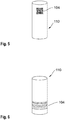
- the in Fig. 6 The cylindrical composite body 110 shown is identified by a bar code 104.
- the bar code 104 is applied to the jacket of the composite body 110.
- the bars of the code are circular bars that encircle the jacket.
Abstract
Bekannt sind zur Energiespeicherung befähigte elektrochemische Zellen mit einem einen Innenraum einschließenden, aus zwei oder mehr Gehäuseteilen zusammengesetztem Gehäuse, und einem in dem Innenraum angeordneten Verbundkörper, der aus mindestens zwei Elektroden und mindestens einem Separator gebildet ist. Es wird vorgeschlagen, bei der Herstellung der elektrochemischen Zellen eine maschinenlesbare Codierung auf mindestens eines der Gehäuseteile oder auf den Verbundkörper oder auf mindestens einen Bestandteil des Verbundkörpers aufzubringen. Insbesondere werden ein hierfür geeignetes Verfahren sowie eine hierfür geeignete Anlage sowie eine gemäß dem Verfahren herstellbare Elektrode vorgeschlagen.

Description
Die nachstehend beschriebene Erfindung betrifft ein Verfahren und eine Anlage zur Herstellung von zur Energiespeicherung befähigter elektrochemischer Zellen sowie eine Elektrode für eine solche elektrochemische Zelle.The invention described below relates to a method and a system for producing electrochemical cells capable of storing energy, and an electrode for such an electrochemical cell.
Zur Energiespeicherung befähigte elektrochemische Zellen sind dazu in der Lage, gespeicherte chemische Energie durch eine Redoxreaktion in elektrische Energie umzuwandeln. Sie umfassen in der Regel eine positive und eine negative Elektrode, die von einem Separator voneinander getrennt sind. Bei einer Entladung werden an der negativen Elektrode durch einen Oxidationsprozess Elektronen freigesetzt. Hieraus resultiert ein Elektronenstrom, der von einem externen elektrischen Verbraucher abgegriffen werden kann, für den die elektrochemische Zelle als Energielieferant dient. Zugleich kommt es zu einem der Elektrodenreaktion entsprechenden lonenstrom innerhalb der Zelle. Dieser lonenstrom durchquert den Separator und wird durch einen Ionen leitenden Elektrolyten ermöglicht.Electrochemical cells capable of storing energy are able to convert stored chemical energy into electrical energy through a redox reaction. They usually include a positive and a negative electrode, which are separated from one another by a separator. In the event of a discharge, electrons are released at the negative electrode through an oxidation process. This results in a stream of electrons that can be tapped from an external electrical consumer for which the electrochemical cell serves as an energy supplier. At the same time, an ion current corresponding to the electrode reaction occurs within the cell. This stream of ions passes through the separator and is made possible by an ion-conducting electrolyte.
Wenn die Entladung reversibel ist, also die Möglichkeit besteht, die bei der Entladung erfolgte Umwandlung von chemischer Energie in elektrische Energie wieder umzukehren und damit die Zelle wieder zu laden, spricht man von einer sekundären Zelle. Die bei sekundären Zellen allgemein übliche Bezeichnung der negativen Elektrode als Anode und die Bezeichnung der positiven Elektrode als Kathode bezieht sich auf die Entladefunktion der elektrochemischen Zelle.If the discharge is reversible, i.e. there is the possibility of reversing the conversion of chemical energy into electrical energy that occurred during the discharge and thus recharging the cell, it is called a secondary cell. The common designation of the negative electrode as the anode and the designation of the positive electrode as the cathode refer to the discharge function of the electrochemical cell.
Die weit verbreiteten sekundären Lithium-Ionen-Zellen basieren auf dem Einsatz von Lithium, welches in Form von Ionen zwischen den Elektroden der Zelle hin und her wandern kann. Lithium-Ionen-Zellen zeichnen sich durch eine hohe Energiedichte aus.The widespread secondary lithium-ion cells are based on the use of lithium, which can migrate back and forth between the electrodes of the cell in the form of ions. Lithium-ion cells are characterized by a high energy density.
Bei der negativen und der positiven Elektrode einer Lithium-Ionen-Zelle handelt es sich in der Regel um sogenannte Kompositelektroden, die neben elektrochemisch aktiven Komponenten (insbesondere Komponenten, die Lithium-Ionen reversibel interkalieren und deinterkalieren können) auch elektrochemisch inaktive Komponenten (Leitmittel, Elektrodenbinder, Stromkollektoren) umfassen. Die Kompositelektroden werden bei der Herstellung einer Lithium-Ionen-Zelle mit einem oder mehreren Separatoren zu einem Verbundkörper kombiniert. Hierbei werden die Elektroden und Separatoren meist unter Druck, gegebenenfalls auch durch Lamination oder durch Verklebung, miteinander verbunden.The negative and positive electrodes of a lithium-ion cell are usually so-called composite electrodes, which in addition to electrochemically active components (in particular components that can reversibly intercalate and deintercalate lithium ions) also have electrochemically inactive components (conductors, electrode binders , Current collectors). In the manufacture of a lithium-ion cell, the composite electrodes are combined with one or more separators to form a composite body. Here, the electrodes and separators are usually connected to one another under pressure, possibly also by lamination or by gluing.
In vielen Ausführungsformen ist der Verbundkörpereben ausgebildet, so dass mehrere Verbundkörperflach aufeinander gestapelt werden können. Sehr häufig wird der Verbundkörper aber in Form eines Wickels gebildet oder zu einem Wickel verarbeitet. In der Regel umfasst der Verbundkörper, unabhängig davon ob gewickelt oder nicht, die Sequenz positive Elektrode / Separator / negative Elektrode. Häufig werden Verbundkörper als sogenannte Bizellen mit den möglichen Sequenzen negative Elektrode/ Separator / positive Elektrode/ Separator / negative Elektrode oder positive Elektrode / Separator / negative Elektrode / Separator / positive Elektrode hergestellt.In many embodiments, the composite body level is designed so that several composite bodies can be stacked flat on top of one another. Very often, however, the composite body is formed in the form of a roll or processed into a roll. As a rule, the composite body, regardless of whether it is wound or not, comprises the sequence positive electrode / separator / negative electrode. Composite bodies are often produced as so-called bicells with the possible sequences negative electrode / separator / positive electrode / separator / negative electrode or positive electrode / separator / negative electrode / separator / positive electrode.
Zur Herstellung der Kompositelektroden wird üblicherweise eine flache Schicht aus einem pastenförmigen Elektrodenmaterial, das neben einem Elektrodenbinder und gegebenenfalls einem Leitmittel eine elektrochemisch aktive Komponente (wird oft auch als Aktivmaterial bezeichnet) in Partikelform enthält, auf einen geeigneten Stromkollektor aufgebracht und anschließend getrocknet. Bevorzugt wird das Elektrodenmaterial auf beide Seiten des Stromkollektors aufgebracht. Produktionstechnisch wird dies meist realisiert, indem die Stromkollektoren als quasi endlose Bänder bereitgestellt werden, die anschließend eine Beschichtungsvorrichtung durchlaufen, in der durch intermittierende Beschichtung eine abgesetzte, in Laufrichtung in definierten Abständen unterbrochene Beschichtung des Stromkollektors erfolgt. Das aus der Beschichtungsvorrichtung austretende Stromkollektorband weist entsprechend in Laufrichtung alternierend beschichtete und unbeschichtete Abschnitte auf.To produce the composite electrodes, a flat layer of a paste-like electrode material, which in addition to an electrode binder and possibly a conductive agent, contains an electrochemically active component (often also referred to as active material) in particle form, is usually applied to a suitable current collector and then dried. The electrode material is preferably applied to both sides of the current collector. In terms of production technology, this is usually achieved by providing the current collectors as quasi-endless belts, which then pass through a coating device in which the current collector is coated with an intermittent coating that is interrupted in the direction of travel at defined intervals. The current collector strip emerging from the coating device has accordingly coated and uncoated sections alternating in the running direction.
Eine Auftrennung des Stromkollektorbandes kann anschließend durch Zerschneiden des Bandes in den unbeschichteten Abschnitten erfolgen. Bei Bedarf kann das Stromkollektorband weiterhin in Streifen geschnitten werden. So lassen sich aus jedem der beschichteten Abschnitte zwei oder mehr einzelne Elektroden herstellen.The current collector strip can then be separated by cutting the strip in the uncoated sections. If necessary, the current collector strip can still be cut into strips. In this way, two or more individual electrodes can be produced from each of the coated sections.
Nach Verarbeitung der so hergestellten Elektroden zu Verbundkörpern erfolgt deren Überführung in ein Gehäuse. Die grundsätzliche Funktionsfähigkeit der Zelle kann dann durch Tränkung des Verbundkörpers mit einem Elektrolyten hergestellt werden. Die so gebildete Zelle kann dann einem Funktions- und Leistungstest unterzogen werden.After the electrodes produced in this way have been processed into composite bodies, they are transferred into a housing. The basic functionality of the cell can then be established by impregnating the composite body with an electrolyte. The cell thus formed can then be subjected to a function and performance test.
Für die Qualität einer Zelle ist die Fehlerfreiheit der hergestellten Elektroden von zentraler Bedeutung. Die Verwendung fehlerhafter Elektroden bedeutet in der Regel, dass damit gebaute Zellen als Ausschussware aussortiert werden müssen.The correctness of the electrodes manufactured is of central importance for the quality of a cell. The use of faulty electrodes usually means that cells built with them have to be sorted out as rejects.
Es wäre wünschenswert, gegebenenfalls auftretende Fehler und Toleranzabweichungen zumindest für die relevantesten Bauteile einer elektrochemischen Zelle möglichst früh zu erkennen und im Idealfall außerhalb einer Toleranz befindliche oder fehlerhafte Bauteile möglichst schnell auszusortieren zu können. Hierzu wäre eine Rückverfolgbarkeit der Bauteile in der Produktionskette erforderlich und natürlich eine entsprechende Möglichkeit zur eindeutigen Identifizierung. Aktuell lassen sich Einzelkomponenten elektrochemischer Zellen bestenfalls Chargen zuordnen.It would be desirable to be able to identify any errors and tolerance deviations that may occur at least for the most relevant components of an electrochemical cell as early as possible and, ideally, to be able to sort out defective or out of tolerance components as quickly as possible. This would require traceability of the components in the production chain and, of course, a corresponding possibility for clear identification. At the moment, individual components of electrochemical cells can at best be assigned to batches.
Zur Lösung dieser Schwierigkeiten werden das nachfolgend beschriebene Verfahren, insbesondere die bevorzugte Ausführungsform des Verfahrens mit den Merkmalen des Anspruchs 1, sowie die nachfolgend beschriebene Anlage und Elektrode, insbesondere deren bevorzugte Ausführungsformen gemäß den Ansprüchen 6 und 8, vorgeschlagen. Weitere bevorzugte Ausgestaltungen des Verfahrens und der Anlage sowie der Elektrode ergeben sich aus den abhängigen Ansprüchen.To solve these difficulties, the method described below, in particular the preferred embodiment of the method with the features of claim 1, and the system and electrode described below, in particular their preferred embodiments according to claims 6 and 8, are proposed. Further preferred configurations of the method and the system as well as the electrode emerge from the dependent claims.
Gegenstand der Erfindung ist die Herstellung von zur Energiespeicherung befähigter elektrochemischer Zellen mit einem Verbundkörper, der aus mindestens zwei Elektroden und mindestens einem Separator gebildet ist. Besonders bevorzugt umfassen die herzustellenden Zellen
- ein einen Innenraum einschließendes, bevorzugt aus zwei oder mehr Gehäuseteilen zusammengesetztes Gehäuse, und
- den in dem Innenraum angeordneten, aus den mindestens zwei Elektroden und dem mindestens einen Separator gebildeten Verbundkörper.
- a housing enclosing an interior space, preferably composed of two or more housing parts, and
- the composite body arranged in the interior space and formed from the at least two electrodes and the at least one separator.
Erfindungsgemäß wird bei der Herstellungderelektrochemischen Zellen eine maschinenlesbare Codierung, insbesondere einen Strichcode und/oder einen 2D-Code, auf den auf Verbundkörper oder auf mindestens ein Bestandteil des Verbundkörpers oder gegebenenfalls auf mindestens eines der Gehäuseteile oder ein sonstiges Bauteil der herzustellenden Zelle, beispielsweise eine Dichtung, aufgetragen. Dies bringt diverse Vorteile mit sich:
- Die Einzelkomponenten einer elektrochemischen Zelle sind gegebenenfalls bis hin zu den Einzelbestandteilen des Verbundkörpers rückverfolgbar.
- Innerhalb einer Anlage zur Herstellung der elektrochemischen Zellen ist aufgrund der individuellen Markierung jederzeit nachvollziehbar, wo sich beispielsweise eine einzelne Elektrode innerhalb eines Produktionsprozesses befindet.
- Beim Testen von Zellen können mögliche Korrelationen zwischen Produktionsparametern und der Funktion oder den Leistungswerten der fertigen Zellen hergestellt werden.
- The individual components of an electrochemical cell can optionally be traced back to the individual components of the composite body.
- Within a system for manufacturing the electrochemical cells, the individual marking makes it possible to trace at any time where, for example, an individual electrode is located within a production process.
- When testing cells, possible correlations can be established between production parameters and the function or performance values of the finished cells.
Unter einer maschinenlesbaren Codierung werden erfindungsgemäß sowohl ein einzelner maschinenlesbarer Code, also beispielsweise ein einzelner Strichcode oder ein einzelner 2D-Code, als auch eine Mehrzahl an maschinenlesbaren Codes, also beispielsweise mehrere 2D-Codes in einer Reihe, verstanden.According to the invention, machine-readable coding is understood to mean both a single machine-readable code, for example a single barcode or a single 2D code, and a plurality of machine-readable codes, for example several 2D codes in a row.
In dem Verbundkörper sind die Elektroden in der Sequenz positive Elektrode / Separator / negative Elektrode angeordnet.In the composite body, the electrodes are arranged in the sequence positive electrode / separator / negative electrode.
Bei den herzustellenden elektrochemischen Zellen handelt es sich bevorzugt um sekundäre Lithium-Ionen-Zellen mit den erwähnten Kompositelektroden aus mit Elektrodenmaterialien beschichteten Stromkollektoren.The electrochemical cells to be produced are preferably secondary lithium-ion cells with the aforementioned composite electrodes made of current collectors coated with electrode materials.
Als Aktivmaterialien für Anode und Kathode der Zellen können im Grunde sämtliche für sekundäre Lithium-Ionen-Zellen bekannten elektrochemisch aktiven Komponenten verwendet werden.In principle, all electrochemically active components known for secondary lithium-ion cells can be used as active materials for the anode and cathode of the cells.
In der negativen Elektrode können als Aktivmaterialien Partikel auf Kohlenstoffbasis wie graphitischer Kohlenstoff oder zur Interkalation von Lithium befähigte, nicht-graphitische Kohlenstoffmaterialien, bevorzugt ebenfalls in Partikelform, eingesetzt werden. Darüber hinaus können auch metallische und halbmetallische Materialien, die mit Lithium legierbar sind, zum Einsatz kommen. So sind beispielsweise die Elemente Zinn, Aluminium, Antimon und Silizium in der Lage, mit Lithium intermetallische Phasen zu bilden. Auch einige Verbindungen von Silizium, Aluminium, Zinn und/oder Antimon können Lithium reversibel ein- und auslagern. Beispielsweise kann in einigen bevorzugten Ausführungsformen das Silizium in oxidischer Form in der negativen Elektrode enthalten sein. Alternativ oder zusätzlich kann auch Lithiumtitanat (Li4Ti5O12) oder ein Derivat desselben in der negativen Elektrode enthalten sein, bevorzugt ebenfalls in Partikelform.In the negative electrode, carbon-based particles such as graphitic carbon or non-graphitic carbon materials capable of intercalating lithium, preferably likewise in particle form, can be used as active materials. In addition, metallic and semi-metallic materials that can be alloyed with lithium can also be used. For example, the elements tin, aluminum, antimony and silicon are able to form intermetallic phases with lithium. Some compounds of silicon, aluminum, tin and / or antimony can also reversibly store and remove lithium. For example, in some preferred embodiments, the silicon can be contained in oxidic form in the negative electrode. Alternatively or additionally, lithium titanate (Li 4 Ti 5 O 12 ) or a derivative thereof can also be contained in the negative electrode, preferably likewise in particle form.
Für die positive Elektrode kommen als Aktivmaterialien beispielsweise Lithium-Metalloxid-Verbindungen und Lithium-Metallphosphat-Verbindungen wie LiCoO2 und LiFePO4 in Frage. Weiterhin gut geeignet sind insbesondere Lithiumnickelmangancobaltoxid (NMC) mit der Summenformel Li-NixMnyCo2O2 (wobei x + y + z typischerweise 1 ist), Lithiummanganspinell (LMO) mit der Summenformel LiMn2O4, oder Lithiumnickelcobaltaluminiumoxid (NCA) mit der Summenformel LiNixCoyAlzO2 (wobei x + y + z typischerweise 1 ist). Auch Derivate hiervon, beispielsweise Lithiumnickelmangancobaltaluminiumoxid (NMCA) mit der Summenformel Li1.11(Ni0.40Mn0.39Co0.16Al0.05)0.89O2 oder Li1+xM-O Verbindungen und/oder Mischungen der genannten Materialien können eingesetzt werden.For example, lithium metal oxide compounds and lithium metal phosphate compounds such as LiCoO 2 and LiFePO 4 can be used as active materials for the positive electrode. Lithium nickel manganese cobalt oxide (NMC) with the empirical formula Li-Ni x Mn y Co 2 O 2 (where x + y + z is typically 1), lithium manganese spinel (LMO) with the empirical formula LiMn 2 O 4 , or lithium nickel cobalt aluminum oxide (NCA) are also particularly suitable ) with the empirical formula LiNi x Co y Al z O 2 (where x + y + z is typically 1). Derivatives thereof, for example lithium nickel manganese cobalt aluminum oxide (NMCA) with the empirical formula Li 1.11 (Ni 0.40 Mn 0.39 Co 0.16 Al 0.05 ) 0.89 O 2 or Li 1 + x MO compounds and / or mixtures of the materials mentioned can also be used.
Die Aktivmaterialien werden bevorzugt in eine Matrix aus einem Elektrodenbinder eingebettet, wobei benachbarte Partikel in der Matrix bevorzugt in unmittelbarem Kontakt miteinander stehen. Übliche Elektrodenbinder basieren beispielsweise auf Polyvinylidenfluorid (PVDF), Polyacrylat oder Carboxymethylzellulose.The active materials are preferably embedded in a matrix made of an electrode binder, with neighboring particles in the matrix preferably being in direct contact with one another. Usual electrode binders are based, for example, on polyvinylidene fluoride (PVDF), polyacrylate or carboxymethyl cellulose.
Weiterhin können den Elektroden Leitmittel zugesetzt werden. Leitmittel dienen dazu, die elektrische Leitfähigkeit der Elektroden zu erhöhen. Übliche Leitmittel sind Ruß und Metallpulver.Conductors can also be added to the electrodes. Conductors are used to increase the electrical conductivity of the electrodes. Common conductive agents are soot and metal powder.
In der fertigen Zelle ist der Verbundkörper bevorzugt mit einem Elektrolyten getränkt, bevorzugt einem Elektrolyten auf der Basis mindestens eines Lithiumsalzes wie beispielsweise Lithiumhexafluorophosphat (LiPF6), das in einem organischen Lösungsmittel gelöst vorliegt (z. B. in einer Mischung organischer Carbonate oder einem cyclischen Ether wie THF oder einem Nitril). Andere einsetzbare Lithium-Salze sind beispielsweise Lithiumtetrafluoroborat (LiBF4), Lithiumbis(trifluoromethansulfonyl)imid (LiTFSI), Lithiumbis(fluorosulfonyl)imid (LiFSI) und Lithiumbis(oxalato)borat (LiBOB).In the finished cell, the composite body is preferably impregnated with an electrolyte, preferably an electrolyte based on at least one lithium salt such as lithium hexafluorophosphate (LiPF 6 ), which is dissolved in an organic solvent (e.g. in a mixture of organic carbonates or a cyclic one Ethers such as THF or a nitrile). Other lithium salts that can be used are, for example, lithium tetrafluoroborate (LiBF4), lithium bis (trifluoromethanesulfonyl) imide (LiTFSI), lithium bis (fluorosulfonyl) imide (LiFSI) and lithium bis (oxalato) borate (LiBOB).
Die Stromkollektoren dienen dazu, im Elektrodenmaterial enthaltene elektrochemisch aktive Komponenten möglichst großflächig elektrisch zu kontaktieren. Bevorzugt bestehen die Stromkollektoren als einem Metall oder sind zumindest oberflächlich metallisiert. Als Metall für den Anodenstromkollektor eignen sich beispielsweise Kupfer oder Nickel oder auch andere elektrisch leitfähige Materialien, insbesondere Kupfer- und Nickellegierungen oder mit Nickel beschichtete Metalle. Auch Edelstahl kommt grundsätzlich in Frage. Als Metall für den Kathodenstromkollektor eignen sich beispielsweise Aluminium oder auch andere elektrisch leitfähige Materialien, insbesondere auch Aluminiumlegierungen.The current collectors are used to make electrical contact with the electrochemically active components contained in the electrode material over as large an area as possible. The current collectors are preferably made of a metal or are at least superficially metallized. Suitable metals for the anode current collector are, for example, copper or nickel or also other electrically conductive materials, in particular copper and nickel alloys or metals coated with nickel. In principle, stainless steel is also an option. Suitable metal for the cathode current collector are, for example, aluminum or other electrically conductive materials, in particular also aluminum alloys.
Bevorzugt werden als Anodenstromkollektor und/oder als Kathodenstromkollektor jeweils Metallfolien, beispielsweise mit einer Dicke im Bereich von 4 µm bis 30 µm, eingesetzt.Metal foils, for example with a thickness in the range from 4 μm to 30 μm, are preferably used as anode current collector and / or as cathode current collector.
Neben Folien können als Stromkollektoren allerdings auch andere Substrate wie metallische oder metallisierte Vliese oder offenporige Schäume oder Streckmetalle verwendet werden.In addition to foils, other substrates such as metallic or metallized fleeces or open-pore foams or expanded metals can also be used as current collectors.
Als Separator kann beispielsweise eine elektrisch isolierende Kunststofffolie verwendet werden. Damit diese von dem Elektrolyten durchdrungen werden kann, weist sie bevorzugt Mikroporen auf. Die Folie kann beispielsweise aus einem Polyolefin oder aus einem Polyetherketon gebildet sein. Nicht ausgeschlossen ist, dass auch Vliese und Gewebe aus solchen oder ähnlichen Kunststoffmaterialien als Separatoren zum Einsatz kommen können.An electrically insulating plastic film, for example, can be used as the separator. So that this can be penetrated by the electrolyte, it preferably has micropores. The film can be formed, for example, from a polyolefin or from a polyether ketone. It is not ruled out that nonwovens and fabrics made of such or similar plastic materials can also be used as separators.
Bei der herzustellenden elektrochemischen Zelle, insbesondere der herzustellenden Lithium-Ionen-Zelle, kann es sich um eine Knopfzelle handeln. Knopfzellen sind zylindrisch ausgebildet und weisen eine Höhe auf, die geringer als ihr Durchmesser ist. Bevorzugt liegt die Höhe der herzustellenden Knopfzelle im Bereich von 4 mm bis 15 mm. Weiter ist es bevorzugt, dass die herzustellende Knopfzelle einen Durchmesser im Bereich von 5 mm bis 25 mm aufweist. Knopfzellen eignen sich beispielsweise zur Versorgung von kleinen elektronischen Geräten wie Uhren, Hörgeräten und kabellosen Kopfhörern mit elektrischer Energie.The electrochemical cell to be produced, in particular the lithium-ion cell to be produced, can be a button cell. Button cells are cylindrical and have a height that is less than their diameter. The height of the button cell to be produced is preferably in the range from 4 mm to 15 mm. It is further preferred that the button cell to be produced has a diameter in the range from 5 mm to 25 mm. Button cells are suitable, for example, for supplying small electronic devices such as watches, hearing aids and wireless headphones with electrical energy.
Die Nennkapazität einer gemäß dem Verfahren hergestellten, als Knopfzelle ausgebildeten Lithium-Ionen-Zelle beträgt in der Regel bis zu 1500 mAh. Bevorzugt liegt die Nennkapazität im Bereich von 100 mAh bis 1000 mAh, besonders bevorzugt im Bereich von 100 bis 800 mAh.The nominal capacity of a lithium-ion cell made according to the method and designed as a button cell is generally up to 1500 mAh. The nominal capacity is preferably in the range from 100 mAh to 1000 mAh, particularly preferably in the range from 100 to 800 mAh.
Besonders bevorzugt ist die herzustellende elektrochemische Zelle, insbesondere die herzustellende Lithium-Ionen-Zelle, eine zylindrische Rundzelle. Zylindrische Rundzellen weisen eine Höhe auf, die größer als ihr Durchmesser ist. Sie eignen sich insbesondere für Anwendungen im Automobilbereich, für E-Bikes oder auch für andere Anwendungen mit hohem Energiebedarf.The electrochemical cell to be produced, in particular the lithium-ion cell to be produced, a cylindrical round cell, is particularly preferred. Cylindrical round cells have a height that is greater than their diameter. They are particularly suitable for applications in the automotive sector, for e-bikes or for other applications with high energy requirements.
Die Höhe herzustellender zylindrischer Rundzellen liegt bevorzugt im Bereich von 15 mm bis 150 mm. Der Durchmesser der zylindrischen Rundzellen liegt bevorzugt im Bereich von 10 mm bis 60 mm. Innerhalb dieser Bereiche sind Formfaktoren von beispielsweise 18 x 65 (Durchmesser mal Höhe in mm) oder 21 x 70 (Durchmesser mal Höhe in mm) besonders bevorzugt. Zylindrische Rundzellen mit diesen Formfaktoren eignen sich insbesondere zur StromversorgungelektrischerAntriebe von Kraftfahrzeugen.The height of cylindrical round cells to be produced is preferably in the range from 15 mm to 150 mm. The diameter of the cylindrical round cells is preferably in the range from 10 mm to 60 mm. Within these ranges, form factors of, for example, 18 x 65 (diameter times height in mm) or 21 x 70 (diameter times height in mm) are particularly preferred. Cylindrical round cells with these form factors are particularly suitable for supplying power to electric drives in motor vehicles.
Die Nennkapazität einer gemäß dem Verfahren hergestellten zylindrischen Rundzelle auf Lithium-Ionen-Basis beträgt bevorzugt bis zu 90000 mAh. Mit dem Formfaktor von 21 x 70 hat die Zelle in einer Ausführungsform als Lithium-Ionen-Zelle bevorzugt eine Nennkapazität im Bereich von 1500 mAh bis 7000 mAh, besonders bevorzugt im Bereich von 3000 bis 5500 mAh. Mit dem Formfaktor von 18 x 65 hat die Zelle in einer Ausführungsform als Lithium-Ionen-Zelle bevorzugt eine Nennkapazität im Bereich von 1000 mAh bis 5000 mAh, besonders bevorzugt im Bereich von 2000 bis 4000 mAh.The nominal capacity of a cylindrical round cell based on lithium ions produced according to the method is preferably up to 90,000 mAh. With the form factor of 21 × 70, the cell in one embodiment as a lithium-ion cell preferably has a nominal capacity in the range from 1500 mAh to 7000 mAh, particularly preferably in the range from 3000 to 5500 mAh. With the form factor of 18 × 65, the cell in one embodiment as a lithium-ion cell preferably has a nominal capacity in the range from 1000 mAh to 5000 mAh, particularly preferably in the range from 2000 to 4000 mAh.
In der Europäischen Union sind Herstellerangaben zu Angaben betreffend die Nennkapazitäten von sekundären Batterien streng reglementiert. So haben etwa Angaben zur Nennkapazität von sekundären Nickel-Cadmium-Batterien auf Messungen gemäß den Normen IEC/EN 61951-1 und IEC/EN 60622, Angaben zur Nennkapazität von sekundären Nickel-Metallhydrid-Batterien auf Messungen gemäß der Norm IEC/EN 61951-2, Angaben zur Nennkapazität von sekundären Lithium-Batterien auf Messungen gemäß der Norm IEC/EN 61960 und Angaben zur Nennkapazität von sekundären Blei-Säure-Batterien auf Messungen gemäß der Norm IEC/EN 61056-1 zu basieren. Jegliche Angaben zu Nennkapazitäten in der vorliegenden Anmeldung basieren bevorzugt ebenfalls auf diesen Normen.In the European Union, manufacturer information on information regarding the nominal capacities of secondary batteries is strictly regulated. For example, information on the nominal capacity of secondary nickel-cadmium batteries is based on measurements in accordance with the standards IEC / EN 61951-1 and IEC / EN 60622, information on the nominal capacity of secondary nickel-metal hydride batteries on measurements in accordance with the standard IEC / EN 61951- 2, Information on the nominal capacity of secondary lithium batteries to be based on measurements in accordance with the IEC / EN 61960 standard and information on the nominal capacity of secondary lead-acid batteries on measurements in accordance with the IEC / EN 61056-1 standard. Any information on nominal capacities in the present application is preferably also based on these standards.
In allen Ausführungsformen, in denen die herzustellende Zelle eine Knopfzelle oder eine zylindrische Rundzelle ist, ist der in dem Innenraum angeordneten Verbundkörper bevorzugt zylindrisch ausgebildet, insbesondere als zylindrischer Wickel, der spiralförmig aufgerollte Elektroden- und Separatorschichten umfasst. Er weist entsprechend bevorzugt zwei endständige, im Wesentlichen kreisrunde Stirnseiten und einen umlaufenden Mantel auf.In all embodiments in which the cell to be produced is a button cell or a cylindrical round cell, the composite body arranged in the interior is preferably of cylindrical design, in particular as a cylindrical winding comprising spirally rolled up electrode and separator layers. Accordingly, it preferably has two terminal, essentially circular end faces and a circumferential jacket.
Die zur Herstellung eines solchen Verbundkörpers benötigten Stromkollektoren und Separatoren sind bevorzugt bandförmig ausgebildet und weisen bevorzugt die folgenden Dimensionen auf:
- Eine Länge im Bereich von 0,3 m bis 25 m
- Eine Breite im Bereich 30 mm bis 145 mm
- A length in the range from 0.3 m to 25 m
- A width in the range 30 mm to 145 mm
Im Falle einer zylindrischen Rundzelle mit dem Formfaktor 18 x 65 weisen die Stromkollektoren beispielsweise bevorzugt
- eine Breite von 56 mm bis 62 mm, bevorzugt von 60 mm, und
- eine Länge von nicht mehr als 1,5 m
- a width of 56 mm to 62 mm, preferably 60 mm, and
- a length of not more than 1.5 m
Im Falle einer zylindrischen Rundzelle mit dem Formfaktor 21 x 70 weisen die Stromkollektoren beispielsweise bevorzugt
- eine Breite von 56 mm bis 68 mm, bevorzugt von 65 mm, und
- eine Länge von nicht mehr als 2,5 m
- a width of 56 mm to 68 mm, preferably 65 mm, and
- a length of not more than 2.5 m
Das Gehäuse der Knopfzelle und der Rundzellen ist bevorzugt im Wesentlichen zylindrisch ausgebildet. In einer bevorzugten Ausführungsform weist das Gehäuse beispielsweise ein becherförmiges erstes Gehäuseteil mit einem Boden und einer umlaufenden Seitenwand und einer Öffnung und ein zweites Gehäuseteil, das die Öffnung verschließt, auf. In vielen weiteren bevorzugten Ausführungsformen sind die Gehäuseteile durch eine Kunststoffdichtung elektrisch voneinander isoliert.The housing of the button cell and the round cell is preferably essentially cylindrical. In a preferred embodiment, the housing has, for example, a cup-shaped first housing part with a base and a circumferential side wall and an opening and a second housing part which closes the opening. In many further preferred embodiments, the housing parts are electrically isolated from one another by a plastic seal.
Grundsätzlich können die im Rahmen des erfindungsgemäßen Verfahrens herzustellenden Verbundkörper auch in einem prismatischen Gehäuse angeordnet werden, insbesondere in der eingangs erwähnten gestapelten Form. Das Gehäuse ist in diesen Ausführungsformen nicht von einer elektrochemischen Zelle umfasst. Vielmehr umschließt es bevorzugt eine Vielzahl von Verbindkörpern.In principle, the composite bodies to be produced within the scope of the method according to the invention can also be arranged in a prismatic housing, in particular in the stacked form mentioned at the beginning. In these embodiments, the housing is not encompassed by an electrochemical cell. Rather, it preferably encloses a large number of connecting bodies.
Wenn das Gehäuse prismatisch ausgebildet ist, dann umfasst das Gehäuse in aller Regel mehrere rechteckige Seitenwände sowie ein polygonales, insbesondere rechteckiges Oberteil und ein polygonales, insbesondere rechteckiges Unterteil. Bevorzugt wird es aus einem ersten und einem zweiten Gehäuseteil zusammengesetzt, wobei das erste Gehäuseteil bevorzugt die Seitenwände und das polygonale Unterteil umfasst während das zweite Gehäuseteil bevorzugt dem polygonalen Oberteil entspricht.If the housing has a prismatic design, the housing generally comprises a plurality of rectangular side walls and a polygonal, in particular rectangular upper part and a polygonal, in particular rectangular lower part. It is preferably composed of a first and a second housing part, the first housing part preferably comprising the side walls and the polygonal lower part, while the second housing part preferably corresponds to the polygonal upper part.
Bevorzugt zeichnet sich das erfindungsgemäße Verfahren durch mindestens eines der unmittelbar folgenden Merkmale a. bis e. aus:
- a. Der Verbundkörper ist zylindrisch ausgebildet und weist die zwei endständigen, im Wesentlichen kreisrunde Stirnseiten und den umlaufenden Mantel aus.
- b. Der maschinenlesbare Code ist auf den Mantel aufgebracht.
- c. Die Außenseite des Mantels wird zumindest teilweise, bevorzugt vollständig, durch eine Separatorwindung und/oder durch eine Klebefolie gebildet.
- d. Die maschinenlesbare Codierung umfasst einen Strichcode oder ist ein Strichcode.
- e. Bei den Strichen des Codes handelt es sich um kreisförmige Striche, die den Mantel umlaufen.
- a. The composite body is cylindrical and has the two terminal, essentially circular end faces and the circumferential jacket.
- b. The machine-readable code is applied to the jacket.
- c. The outside of the jacket is at least partially, preferably completely, formed by a separator winding and / or by an adhesive film.
- d. The machine-readable coding comprises a bar code or is a bar code.
- e. The bars of the code are circular bars that encircle the jacket.
Besonders bevorzugt sind die unmittelbar vorstehenden Merkmale a., b., d. und e. in Kombination realisiert.Particularly preferred are the immediately preceding features a., B., D. and e. realized in combination.
Die umlaufend aufgebrachte Codierung ermöglicht eine automatisierte Lesbarkeit bei der Verarbeitung des Verbundkörpers von allen Seiten.The encoding applied all round enables automated readability when processing the composite body from all sides.
Bei einem erfindungsgemäß verwendbaren Strichcode kann es sich insbesondere um einen Code handeln, der in einer der folgenden internationalen Normen festgelegt ist:
- ISO/IEC 15420 (Handelsstrichcodes EAN, UPC, IAN, JAN)
- ISO/IEC 16390 (Code der 2/5-Familie)
- ISO/IEC 16388 (Code 39)
- ISO/IEC 15417 (Code128)
- ISO / IEC 15420 (trade bar codes EAN, UPC, IAN, JAN)
- ISO / IEC 16390 (2/5 family code)
- ISO / IEC 16388 (Code 39)
- ISO / IEC 15417 (Code128)
In einigen Ausführungsformen ist es bevorzugt, einen anderen Code als einen Strichcode, beispielsweise einen 2D-Code, auf den Verbundkörper oder ein anderes Bauteil der herzustellenden Zelle aufzubringen. Als 2D-Codes kommen beispielsweise Codes in Frage, die in einer derfolgenden internationalen Normen festgelegt sind:
- ISO/IEC 18004 (QR-Code)
- ISO/IEC 16022 (DataMatrix-Code)
- ISO/IEC JTC1 SC31 (Han-Xin-Code)
- ISO/IEC 15417
- ISO / IEC 18004 (QR code)
- ISO / IEC 16022 (DataMatrix code)
- ISO / IEC JTC1 SC31 (Han-Xin code)
- ISO / IEC 15417
In einigen Ausführungsformen kann es sich bei dem maschinenlesbaren Code auch um einen Composite-Code handeln, also einen Code, der sich aus einem linearen Barcode und einem 2D-Code zusammensetzt.In some embodiments, the machine-readable code can also be a composite code, that is to say a code which is composed of a linear barcode and a 2D code.
In weiteren Ausführungsformen kann es sich bei dem Code auch um eine alphanumerische Zeichen umfassende Codierung, also beispielsweise eine aus Zahlen bestehende Codierung, eine aus Buchstaben bestehende Codierung oder um eine gemischte, also Zahlen und Buchstaben und gegebenenfalls auch Sonderzeichen (beispielsweise Satzzeichen wie Punkt und Komma, Plus und Minuszeichen, Klammern oder Buchstaben mit Diakritika) umfassende Codierung, handeln. Selbstverständlich kann die Codierung auch Zeichen aus nicht-europäischen Sprachen, beispielsweise chinesische, japanische, koreanische oder kyrillische Zeichen umfassen.In further embodiments, the code can also be an encoding comprising alphanumeric characters, for example a coding consisting of numbers, a coding consisting of letters or a mixed one, i.e. numbers and letters and possibly also special characters (for example punctuation marks such as periods and commas , Plus and minus signs, brackets or letters with diacritics) comprehensive coding, act. Of course, the coding can also include characters from non-European languages, for example Chinese, Japanese, Korean or Cyrillic characters.
In einigen besonders bevorzugten Ausführungsformen ist es auch möglich, dass die maschinenlesbare Codierung einen Strichcode oder einen 2D-Code oder einen Composite-Code in Kombination mit einem oder mehreren alphanumerischen Zeichen oder einer Abfolge alphanumerischer Zeichen umfasst.In some particularly preferred embodiments, it is also possible that the machine-readable coding comprises a bar code or a 2D code or a composite code in combination with one or more alphanumeric characters or a sequence of alphanumeric characters.
Weitere Bestandteile der herzustellenden Zelle, die erfindungsgemäß bevorzugt mit der maschinenlesbaren Codierung versehen werden, sind die Gehäuseteile sowie gegebenenfalls die erwähnte Dichtung, die zwischen den Gehäuseteilen angeordnet werden kann.Further components of the cell to be produced, which according to the invention are preferably provided with the machine-readable coding, are the housing parts and, if appropriate, the mentioned seal, which can be arranged between the housing parts.
In vielen Fällen ist es bevorzugt, die maschinenlesbare Codierung unmittelbar auf den Verbundkörper, den mindestens einen Bestandteil des Verbundkörpers oder das mindestens eine der Gehäuseteile oder eines der erwähnten sonstigen Bauteile der herzustellenden Zelle aufzubringen. Es kann aber auch bevorzugt sein, die Codierung auf mindestens ein Etikett aufzubringen, das dann auf den Verbundkörper, auf mindestens eines seiner Bestandteile oder auf ein sonstiges Bauteil der Zelle aufgebracht wird, insbesondere durch Verklebung.In many cases it is preferred to apply the machine-readable coding directly to the composite body, the at least one component of the composite body or the at least one of the housing parts or one of the other components mentioned of the cell to be produced. However, it can also be preferred to apply the coding to at least one label, which is then applied to the composite body, to at least one of its components or to another component of the cell, in particular by gluing.
In einer besonders bevorzugten Variante des erfindungsgemäßen Verfahrens wird mindestens eine der Elektroden des Verbundkörpers mit einer maschinenlesbaren Codierung versehen. Insbesondere werden sowohl die positive als auch die negative Elektrode mit einer maschinenlesbaren Codierung versehen.In a particularly preferred variant of the method according to the invention, at least one of the electrodes of the composite body is provided with a machine-readable code. In particular, both the positive and the negative electrode are provided with a machine-readable code.
So ist es besonders bevorzugt, dass in dieser besonders bevorzugten Variante zur Herstellung der Elektroden der elektrochemischen Zellen
- a. mindestens eine Schicht aus einem Elektrodenmaterial auf einen eine Beschichtungsvorrichtung durchlaufenden bandförmigen Stromkollektor aufgebracht wird,
- b. das Aufbringen der Schicht intermittierend erfolgt, so dass der Stromkollektor nach Durchlaufen der Beschichtungsvorrichtung in Längsrichtung in mit Elektrodenmaterial beschichtete Abschnitte und dazwischen liegende unbeschichtete Abschnitte unterteilbar ist, und
- c. der mit Elektrodenmaterial beschichtete bandförmige Stromkollektor mindestens eine Trennvorrichtung durchläuft, in der
- in Längsrichtung die beschichteten und die unbeschichteten Abschnitte und
- in Querrichtung die unbeschichteten Abschnitte
- d. jedem der beschichteten Abschnitte eine maschinenlesbare Codierung zugeordnet wird, die den jeweiligen Abschnitt kennzeichnet, und
- e. die Codierung derart auf den bandförmigen Stromkollektor und/oder das darauf aufgebrachte Elektrodenmaterial aufgebracht wird, dass sie nach dem Durchlaufen der mindestens einen Trennvorrichtung auf jedem der Teilabschnitte abrufbar ist und eine Zuordenbarkeit der Teilabschnitte zu dem codierten Abschnitt ermöglicht.
- a. at least one layer of an electrode material is applied to a band-shaped current collector passing through a coating device,
- b. the application of the layer takes place intermittently, so that after passing through the coating device, the current collector can be divided in the longitudinal direction into sections coated with electrode material and uncoated sections in between, and
- c. the strip-shaped current collector coated with electrode material passes through at least one separating device in which
- in the longitudinal direction the coated and the uncoated sections and
- in the transverse direction the uncoated sections
- d. each of the coated sections is assigned a machine-readable code which identifies the respective section, and
- e. the coding is applied to the strip-shaped current collector and / or the electrode material applied thereon in such a way that it can be called up on each of the subsections after passing through the at least one separating device and enables the subsections to be assigned to the coded section.
Die abgetrennten Teilabschnitte entsprechen den Elektroden der herzustellenden Zellen, sie können gegebenenfalls unmittelbar weiterverarbeitet werden.The separated sections correspond to the electrodes of the cells to be produced; they can optionally be further processed immediately.
Diese besonders bevorzugte Variante des Verfahrens ermöglicht es, Elektroden nach dem Schneidprozess in jedem Stadium des erfindungsgemäßen Verfahrens einem Stromkollektorband, einem Abschnitt auf dem Stromkollektorband und gegebenenfalls einer Spur innerhalb des Abschnitts zuzuordnen.This particularly preferred variant of the method makes it possible, after the cutting process, to assign electrodes to a current collector strip, a section on the current collector strip and possibly a track within the section in every stage of the method according to the invention.
Besonders bevorzugt wird der bandförmige Stromkollektor beidseitig mit einer Schicht aus dem jeweiligen Elektrodenmaterial beschichtet.The band-shaped current collector is particularly preferably coated on both sides with a layer of the respective electrode material.
In einer Weiterbildung der besonders bevorzugten Variante zeichnet sich das erfindungsgemäße Verfahren durch mindestens eines der unmittelbar folgenden Merkmale a. und b. aus:
- a. Die maschinenlesbare Codierung umfasst einen Strichcode oder ist ein Strichcode.
- b. Die Codierung, insbesondere der Strichcode, umfasst Linien oder besteht aus Linien, die senkrecht oder schräg zur Haupterstreckungsrichtung des bandförmigen Stromkollektors auf den bandförmigen Stromkollektor und/oder das darauf aufgebrachte Elektrodenmaterial aufgebracht werden.
- a. The machine-readable coding comprises a bar code or is a bar code.
- b. The coding, in particular the bar code, comprises lines or consists of lines which are applied perpendicularly or at an angle to the main direction of extent of the ribbon-shaped current collector on the ribbon-shaped current collector and / or the electrode material applied to it.
Besonders bevorzugt sind die unmittelbar vorstehenden Merkmale a. und b. in Kombination miteinander realisiert.Particularly preferred are the immediately above features a. and b. realized in combination with each other.
Die Verwendung eines Strichcodes bringt bei der besonders bevorzugten Variante besondere Vorteile mit sich. So können die Linien des Strichcodes durch einen entsprechenden Längsschnitt in Haupterstreckungsrichtung des bandförmigen Stromkollektors zerteilt werden, ohne dass Information verloren geht. Ein Strichcode kann entsprechend nach Durchlaufen der mindestens einen Trennvorrichtung alle Teilabschnitte eines beschichteten Abschnitts kennzeichnen.The use of a bar code in the particularly preferred variant has particular advantages. Thus, the lines of the bar code can be divided by a corresponding longitudinal cut in the main direction of extent of the band-shaped current collector without information being lost. A bar code can accordingly identify all subsections of a coated section after passing through the at least one separating device.
Einfacher wäre es, die Linien des Strichcodes in der Haupterstreckungsrichtung des bandförmigen Stromkollektors aufzubringen. Die beschriebenen Vorteile überwiegen aber die Schwierigkeiten, die sich bei der Aufbringung senkrecht oder schräg ausgerichteter Linien ergeben.It would be easier to apply the lines of the bar code in the main direction of extent of the band-shaped current collector. The advantages described outweigh the difficulties that arise when applying perpendicular or oblique lines.
Bei einer schrägen Ausrichtung der Linien des Strichcodes schließen diese mit einem Längsrand des bandförmigen Stromkollektors bevorzugt einen Winkel von 89,9° bis 1°, besonders bevorzugt von 89,9° bis 25°, insbesondere von 89,9° bis 45°, ein.If the lines of the bar code are aligned obliquely, they preferably form an angle of 89.9 ° to 1 °, particularly preferably 89.9 ° to 25 °, in particular 89.9 ° to 45 °, with a longitudinal edge of the band-shaped current collector .
Die Schicht aus dem Elektrodenmaterial wird meist in Form einer rechteckigen oder streifenförmigen Fläche auf den Stromkollektor aufgebracht. Die beschichteten Abschnitte weisen somit bevorzugt eine rechteckige oder streifenförmige Geometrie auf. In der besonders bevorzugten Variante weisen die Linien des Strichcodes bevorzugt eine Länge auf, welche der Breite der beschichteten Fläche entspricht oder diese überschreitet.The layer of the electrode material is usually applied to the current collector in the form of a rectangular or strip-shaped area. The coated sections thus preferably have a rectangular or strip-shaped geometry. In the particularly preferred variant, the lines of the bar code preferably have a length which corresponds to or exceeds the width of the coated surface.
In einer alternativen Weiterbildung der besonders bevorzugten Variante zeichnet sich das erfindungsgemäße Verfahren durch mindestens eines der unmittelbar folgenden Merkmale a. bis c. aus:
- a. Die Codierung umfasst mehrere Einzelcodes, welche in Querrichtung versetzt zueinander auf den bandförmigen Stromkollektor und/oder dem darauf aufgebrachte Elektrodenmaterial aufgebracht werden.
- b. Die Anzahl der Einzelcodes je beschichtetem Abschnitt entspricht der Anzahl der Teilabschnitte, in welche der Abschnitt aufgetrennt wird.
- c. Bei der Codierung handelt es sich um einen Code aus der Gruppe mit Strichcode und 2D-Code.
- a. The coding comprises several individual codes, which are offset from one another in the transverse direction be applied to the band-shaped current collector and / or the electrode material applied thereon.
- b. The number of individual codes per coated section corresponds to the number of subsections into which the section is divided.
- c. The coding is a code from the group with barcode and 2D code.
Besonders bevorzugt sind die unmittelbar vorstehenden Merkmale a. bis c. in Kombination miteinander realisiert.Particularly preferred are the immediately above features a. to c. realized in combination with each other.
Die Einzelcodes sind in dieser Weiterbildung bevorzugt derart platziert, dass ihre Lesbarkeit nach dem Durchlaufen der mindestens einen Trennvorrichtung nicht beeinträchtigt ist und dass jeder der Teilabschnitte mit einem der Einzelcodes gekennzeichnet ist. Die Kennzeichnung eines jeden Teilabschnitts mit einem Einzelcode hat den Vorteil, dass bei entsprechenden Informationsgehalt des Codes grundsätzlich auch zwischen einzelnen Teilabschnitten eines Abschnitts unterschieden werden kann.In this development, the individual codes are preferably placed in such a way that their readability is not impaired after passing through the at least one separating device and that each of the subsections is identified with one of the individual codes. The identification of each sub-section with an individual code has the advantage that, given the corresponding information content of the code, a distinction can in principle also be made between individual sub-sections of a section.
In dieser Weiterbildung ist es bevorzugt, dass die Striche eines Strichcodes längs zur Haupterstreckungsrichtung des bandförmigen Stromkollektors ausgerichtet sind und nicht senkrecht oder schräg dazu.In this development, it is preferred that the bars of a bar code are aligned along the main direction of extent of the band-shaped current collector and not perpendicular or at an angle to it.
Es ist bevorzugt, dass sich die besonders bevorzugte Variante des Verfahrens weiter durch das folgende zusätzliche Merkmal a. auszeichnet:
- a. Die einem beschichteten Abschnitt zugeordnete Codierung wird in mindestens einem der diesem Abschnitt unmittelbar angrenzenden unbeschichteten Abschnitte auf den Stromkollektor aufgebracht.
- a. The coding assigned to a coated section is applied to the current collector in at least one of the uncoated sections immediately adjacent to this section.
Es ist bevorzugt, die Codierung nach dem Aufbringen des Elektrodenmaterials auf den Stromkollektor aufzubringen. Es ist aber durchaus auch möglich, die Codierung bereits vor dem Durchlaufen der Beschichtungsvorrichtung auf den Stromkollektor aufzubringen. Dies kann sogar besonders vorteilhaft sein, die Codierung kann in dieser Ausführungsform nämlich auch als Markierung eines zu beschichteten Abschnitts dienen und somit helfen, die intermittierende Beschichtung des Stromkollektors zu steuern. Der Beschichtungsvorrichtung kann in dieser Ausführungsform eine Einrichtung zur Erkennung des aufgebrachten Codes zugeordnet sein.It is preferred to apply the coding to the current collector after the electrode material has been applied. However, it is also entirely possible to apply the coding to the current collector before it passes through the coating device. This can even be particularly advantageous, namely in this embodiment the coding can also be used as a marking of something to be coated Serve section and thus help to control the intermittent coating of the current collector. In this embodiment, the coating device can be assigned a device for recognizing the applied code.
Besonders bevorzugt wird die Codierung auf dem Stromkollektor, insbesondere in dem unbeschichteten Abschnitt, derart platziert, dass sie beim Durchtrennen des unbeschichteten Abschnitts in Querrichtung nicht beschädigt wird.The coding is particularly preferably placed on the current collector, in particular in the uncoated section, in such a way that it is not damaged in the transverse direction when the uncoated section is severed.
In einem einfachen Fall umfasst die Codierung eines Abschnitts eine Nummer, anhand der der Abschnitt eindeutig identifiziert werden kann. Besonders bevorzugt werden die Abschnitte laufend durchnummeriert.In a simple case, the coding of a section comprises a number by means of which the section can be uniquely identified. The sections are particularly preferably numbered consecutively.
Es ist weiterhin bevorzugt, dass sich die besonders bevorzugte Variante des Verfahrens durch mindestens eines der unmittelbar folgenden zusätzlichen Merkmale a. und b. auszeichnet:
- a. Die Codierung beinhaltet, gegebenenfalls neben der Kennzeichnung des Abschnitts, das Ergebnis mindestens einer Prüfung, der der Abschnitt unterzogen wurde.
- b. Die Codierung beinhaltet, gegebenenfalls neben der Kennzeichnung des Abschnitts, Informationen zur Länge und/oder zur Breite des Abschnitts.
- a. In addition to the identification of the section, the coding contains the result of at least one test to which the section was subjected.
- b. The coding contains, possibly in addition to the identification of the section, information on the length and / or the width of the section.
Bei der Prüfung kann es sich beispielsweise um eine Prüfung der Dicke der Elektrodenbeschichtung handeln.The test can be, for example, a test of the thickness of the electrode coating.
Eine gemäß der besonders bevorzugten Variante des erfindungsgemäßen Verfahrens hergestellte Elektrode zeichnet sich durch das folgende Merkmal a. aus:
- a. Sie umfasst einen maschinenlesbaren Code, welcher Informationen beinhaltet, die eine Zuordenbarkeit der Elektrode zu einem mit Elektrodenmaterial beschichteten Abschnitt eines bandförmigen Stromkollektors, aus dem die Elektrode gefertigt wurde, ermöglichen.
- a. It comprises a machine-readable code which contains information that enables the electrode to be assigned to a section of a strip-shaped current collector from which the electrode was manufactured, which section is coated with electrode material.
Betreffend bevorzugte Ausführungsformen der Elektrode, ihrer Einzelbestandteile, des Codes und dessen Positionierung wird zur Vermeidung von Wiederholungen auf obenstehende Ausführungen Bezug genommen. Ungeachtet dessen ist aber noch einmal zu betonen, dass sich die Elektrode besonders bevorzugt durch mindestens eines der unmittelbar folgenden Merkmale a. und b., insbesondere durch eine Kombination der unmittelbar folgenden Merkmale a. und b., auszeichnet:
- a. Die Elektrode ist bandförmig ausgebildet.
- b. Die Codierung, insbesondere der Strichcode, umfasst Linien oder besteht aus Linien, die senkrecht oder schräg zur Haupterstreckungsrichtung der Elektrode ausgerichtet sind.
- a. The electrode is designed in the form of a band.
- b. The coding, in particular the bar code, comprises lines or consists of lines which are oriented perpendicular or obliquely to the main direction of extent of the electrode.
Eine zur Durchführung des erfindungsgemäßen Verfahrens geeignete Anlage, insbesondere eine zur Durchführung der besonders bevorzugten Variante des erfindungsgemäßen Verfahrens geeignete Anlage, zeichnet sich insbesondere durch eine Kombination der folgenden Merkmale aus:
- a. Sie umfasst eine Beschichtungsvorrichtung, in der eine Schicht aus einem Elektrodenmaterial intermittierend auf einen die Beschichtungsvorrichtung durchlaufenden bandförmigen Stromkollektor aufgebracht wird.
- b. Sie umfasst mindestens eine Trennvorrichtung, die dazu ausgebildet ist, den mit Elektrodenmaterial beschichteten bandförmigen Stromkollektor in Längsrichtung und in Querrichtung zu durchtrennen.
- c. Sie umfasst eine Vorrichtung zur Aufbringung einer maschinenlesbaren Codierung auf den bandförmigen Stromkollektor und/oder das darauf aufgebrachte Elektrodenmaterial, welche dazu ausgebildet ist,
- Linien senkrecht oder schräg zur Haupterstreckungsrichtung des bandförmigen Stromkollektors
und/oder - mehrere Einzelcodes in Querrichtung versetzt zueinander
- Linien senkrecht oder schräg zur Haupterstreckungsrichtung des bandförmigen Stromkollektors
- a. It comprises a coating device in which a layer of an electrode material is applied intermittently to a band-shaped current collector passing through the coating device.
- b. It comprises at least one separating device which is designed to cut through the strip-shaped current collector coated with electrode material in the longitudinal direction and in the transverse direction.
- c. It comprises a device for applying a machine-readable code to the strip-shaped current collector and / or the electrode material applied to it, which is designed to
- Lines perpendicular or oblique to the main direction of extent of the ribbon-shaped current collector
and or - several individual codes offset from one another in the transverse direction
- Lines perpendicular or oblique to the main direction of extent of the ribbon-shaped current collector
Die Beschichtungsvorrichtung kann beispielsweise eine Düse umfassen, wie sie in der
Ferner ist es möglich, die Codierung in Form eines Etiketts aufzubringen, insbesondere aufzukleben. Bei der Vorrichtung zur Aufbringung der maschinenlesbaren Codierung kann es sich somit auch um eine Etikettiervorrichtung handeln.It is also possible to apply the coding in the form of a label, in particular to glue it on. The device for applying the machine-readable code can therefore also be a labeling device.
Bei dem Etikett kann es sich in einigen bevorzugten Ausführungsformen auch um einen RFID-Tag, der die maschinenlesbare Codierung umfasst, handeln. Die Codierung kann in diesem Fall über Funk ausgelesen werden.In some preferred embodiments, the label can also be an RFID tag that includes the machine-readable coding. In this case, the coding can be read out by radio.
Weitere Merkmale der Erfindung sowie aus der Erfindung resultierende Vorteile ergeben sich aus den Zeichnungen sowie aus der nachfolgenden Beschreibung der Zeichnungen. Die nachfolgend beschriebenen Ausführungsformen dienen lediglich zur Erläuterung und zum besseren Verständnis der Erfindung und sind in keiner Weise einschränkend zu verstehen.Further features of the invention and advantages resulting from the invention emerge from the drawings and from the following description of the drawings. The embodiments described below serve only to explain and better understand the invention and are in no way to be understood as restrictive.
In den Zeichnungen zeigen schematisch
-
Fig. 1 eine Ausführungsform eines gemäß der besonders bevorzugten Variante des erfindungsgemäßen Verfahrens mit einem Strichcode versehenen und mit einer Schicht aus einem Elektrodenmaterial beschichteten Stromkollektors, -
Fig. 2 eine weitere Ausführungsform eines gemäß der besonders bevorzugten Variante des erfindungsgemäßen Verfahrens mit einem Strichcode versehenen und mit einer Schicht aus einem Elektrodenmaterial beschichteten Stromkollektors, -
Fig. 3 eine Ausführungsform eines gemäß der besonders bevorzugten Variante des erfindungsgemäßen Verfahrens mit mehrere Einzelcodes versehenen und mit einer Schicht aus einem Elektrodenmaterial beschichteten Stromkollektors, -
Fig. 4 eine weitere Ausführungsform eines gemäß der besonders bevorzugten Variante des erfindungsgemäßen Verfahrens mit mehrere Einzelcodes versehenen und mit einer Schicht aus einem Elektrodenmaterial beschichteten Stromkollektors, -
Fig. 5 eine Ausführungsform eines zylindrischen Verbundkörpers, auf dessen Mantel ein maschinenlesbarer Code aufgetragen ist. -
Fig. 6 eine weitere Ausführungsform eines zylindrischen Verbundkörpers, auf dessen Mantel ein maschinenlesbarer Code aufgetragen ist.
-
Fig. 1 an embodiment of a current collector provided with a barcode according to the particularly preferred variant of the method according to the invention and coated with a layer of an electrode material, -
Fig. 2 a further embodiment of a current collector provided with a barcode according to the particularly preferred variant of the method according to the invention and coated with a layer of an electrode material, -
Fig. 3 an embodiment of a current collector provided with several individual codes according to the particularly preferred variant of the method according to the invention and coated with a layer of an electrode material, -
Fig. 4 a further embodiment of a current collector provided with several individual codes according to the particularly preferred variant of the method according to the invention and coated with a layer of an electrode material, -
Fig. 5 an embodiment of a cylindrical composite body, on the jacket of which a machine-readable code is applied. -
Fig. 6 a further embodiment of a cylindrical composite body, on the jacket of which a machine-readable code is applied.
Der in
Bei zwei Längsschnitten entlang den parallel zur Haupterstreckungsrichtung H ausgerichteten Linien 105 und 106 durch den Stromkollektor 100 werden die beschichteten Abschnitte 101 und 103 in jeweils drei Teilabschnitte unterteilt. Jeder der aus dem Abschnitt 103 resultierenden Teilabschnitte ist auch nach dem Längsschnitt durch den Strichcode 104 gekennzeichnet, der bei den Längsschnitten ebenfalls durchtrennt wird.In the case of two longitudinal sections along the
Ein Querschnitt durch einen nicht mit dem Strichcode 104 versehenen Bereich des Abschnitts 102 entlang der Linie 107 trennt die Abschnitte 101 und 103 voneinander.A cross section through a region of the
Der in
Bei zwei Längsschnitten entlang den parallel zur Haupterstreckungsrichtung H ausgerichteten Linien 105 und 106 durch den Stromkollektor 100 werden die beschichteten Abschnitte 101 und 103 in jeweils drei Teilabschnitte unterteilt. Jeder der aus dem Abschnitt 101 resultierenden Teilabschnitte ist auch nach dem Längsschnitt durch den Strichcode 104 gekennzeichnet, der bei den Längsschnitten ebenfalls durchtrennt wird.In the case of two longitudinal sections along the
Die resultierenden Teilabschnitte sind lediglich anhand des Strichcodes nicht voneinander unterscheidbar. Es kann daher vorgesehen sein, zusätzlich zu dem Strichcode Nummern oder Zeichen auf den Stromkollektor aufzubringen, die eine Unterscheidung der Teilabschnitte ermöglichen. Beispielhaftsind die aus den Längsschnitten resultierenden Teilabschnitte in
Ein Querschnitt durch den Abschnitt 102 entlang der Linie 107 trennt die Abschnitte 101 und 103 voneinander.A cross section through
Der in
Bei vier Längsschnitten entlang der parallel zur Haupterstreckungsrichtung H des Stromkollektors 101 ausgerichteten Linien 105, 106. 108 und 109 durch den Stromkollektor 100 werden die beschichteten Abschnitte 101 und 103 in jeweils fünf Teilabschnitte unterteilt. Jeder der aus dem Abschnitt 101 resultierenden Teilabschnitte istauch nach den Längsschnitten durch einen der Einzelcodes 104 gekennzeichnet und kann von anderen Teilabschnitten mit Hilfe der weiteren individuellen Nummer unterschieden werden.In the case of four longitudinal sections along the
Ein Querschnitt durch den Abschnitt 102 entlang der Linie 107 trennt die Abschnitte 101 und 103 voneinander.A cross section through
Der in
Bei drei Längsschnitten entlang der parallel zur Haupterstreckungsrichtung ausgerichteten Linien 105, 106 und 108 durch den Stromkollektor 100 werden die beschichteten Abschnitte 101 und 103 in jeweils vier Teilabschnitte unterteilt. Jeder der aus dem Abschnitt 101 resultierenden Teilabschnitte ist auch nach den Längsschnitten durch einen der Einzelcodes 104 gekennzeichnet und kann von anderen Teilabschnitten mit Hilfe der weiteren individuellen Nummer unterschieden werden.In the case of three longitudinal sections along the
Ein Querschnitt durch den Abschnitt 102 entlang der Linie 107 trennt die Abschnitte 101 und 103 voneinander.A cross section through
Der in
Die Außenseite des Mantels kann durch eine äußere Windung eines der Separatoren des Verbundkörpers 110 oder durch eine Klebefolie gebildet sein. Der QR-Code 104 (oder auch ein anderer maschinenlesbarer Code) kann unmittelbar auf die Außenseite, also insbesondere auf die Windung des Separators oder die Klebefolie, aufgebracht sein, beispielsweise mittels eines Druckverfahrens. Alternativ kann sich der QR-Code 104 (oder auch ein anderer maschinenlesbarer Code) auch auf einem Etikett befinden, das auf die Außenseite aufgeklebt wurde.The outside of the jacket can be formed by an outer turn of one of the separators of the
Es ist auch möglich, dass der QR-Code 104 (oder auch ein anderer maschinenlesbarer Code) auf einen Klebestreifen aufgebracht ist, der zur Fixierung einer außenliegenden Windung des durch Wicklung gebildeten Verbundkörpers 110, beispielsweise einer Windung eines Separatorbandes, auf die Außenseite des Mantels des Verbundkörpers 110 aufgeklebt ist. Oder mit anderen Worten, ein Klebeetikett mit einem darauf aufgebrachten QR-Code kann zur Fixierung des Wickels eingesetzt werden.It is also possible that the QR code 104 (or another machine-readable code) is applied to an adhesive strip that is used to fix an outer turn of the
Der in
Claims (8)
Priority Applications (7)
| Application Number | Priority Date | Filing Date | Title |
|---|---|---|---|
| EP20183540.2A EP3933963A1 (en) | 2020-07-01 | 2020-07-01 | Method and apparatus for manufacturing electrochemical cells and electrode for an electrochemical cell |
| EP21739340.4A EP4176474A1 (en) | 2020-07-01 | 2021-07-01 | Method and system for producing electrochemical cells, and electrode for an electrochemical cell |
| US18/009,779 US20230261208A1 (en) | 2020-07-01 | 2021-07-01 | Method and system for producing electrochemical cells, and electrode for an electrochemical cell |
| CN202180047138.5A CN115735284A (en) | 2020-07-01 | 2021-07-01 | Method and apparatus for manufacturing electrochemical cell and electrode for electrochemical cell |
| KR1020237003060A KR20230029917A (en) | 2020-07-01 | 2021-07-01 | Electrochemical cells, and methods and systems for producing electrodes for electrochemical cells |
| JP2022581347A JP2023531784A (en) | 2020-07-01 | 2021-07-01 | Methods and systems for manufacturing electrochemical cells and electrodes for electrochemical cells |
| PCT/EP2021/068195 WO2022003109A1 (en) | 2020-07-01 | 2021-07-01 | Method and system for producing electrochemical cells, and electrode for an electrochemical cell |
Applications Claiming Priority (1)
| Application Number | Priority Date | Filing Date | Title |
|---|---|---|---|
| EP20183540.2A EP3933963A1 (en) | 2020-07-01 | 2020-07-01 | Method and apparatus for manufacturing electrochemical cells and electrode for an electrochemical cell |
Publications (1)
| Publication Number | Publication Date |
|---|---|
| EP3933963A1 true EP3933963A1 (en) | 2022-01-05 |
Family
ID=71452053
Family Applications (2)
| Application Number | Title | Priority Date | Filing Date |
|---|---|---|---|
| EP20183540.2A Pending EP3933963A1 (en) | 2020-07-01 | 2020-07-01 | Method and apparatus for manufacturing electrochemical cells and electrode for an electrochemical cell |
| EP21739340.4A Pending EP4176474A1 (en) | 2020-07-01 | 2021-07-01 | Method and system for producing electrochemical cells, and electrode for an electrochemical cell |
Family Applications After (1)
| Application Number | Title | Priority Date | Filing Date |
|---|---|---|---|
| EP21739340.4A Pending EP4176474A1 (en) | 2020-07-01 | 2021-07-01 | Method and system for producing electrochemical cells, and electrode for an electrochemical cell |
Country Status (6)
| Country | Link |
|---|---|
| US (1) | US20230261208A1 (en) |
| EP (2) | EP3933963A1 (en) |
| JP (1) | JP2023531784A (en) |
| KR (1) | KR20230029917A (en) |
| CN (1) | CN115735284A (en) |
| WO (1) | WO2022003109A1 (en) |
Families Citing this family (1)
| Publication number | Priority date | Publication date | Assignee | Title |
|---|---|---|---|---|
| WO2024047984A1 (en) * | 2022-08-29 | 2024-03-07 | パナソニックエナジー株式会社 | Electrode plate, electrode body, and battery |
Citations (8)
| Publication number | Priority date | Publication date | Assignee | Title |
|---|---|---|---|---|
| EP0275771B1 (en) | 1986-12-22 | 1989-08-09 | Elf Atochem S.A. | Process for the preparation of tetrahydro-1,1,2,2-perfluoroalcanols and their esters |
| EP0825659A2 (en) * | 1996-08-22 | 1998-02-25 | Dai Nippon Printing Co., Ltd. | Electrode plate for secondary battery with nonaqueous electrolyte and process for producing the same |
| EP1403943A2 (en) * | 2002-09-24 | 2004-03-31 | Wilson Greatbatch Ltd. | Current collector matrix identifier |
| JP2006032223A (en) * | 2004-07-20 | 2006-02-02 | Japan Storage Battery Co Ltd | Storage battery and manufacturing method of storage battery |
| WO2013018254A1 (en) * | 2011-07-29 | 2013-02-07 | 株式会社日立製作所 | Electrode sheet-laminated lithium ion battery and method for manufacturing same |
| JP2017220356A (en) * | 2016-06-07 | 2017-12-14 | トヨタ自動車株式会社 | Marking device |
| WO2019077943A1 (en) * | 2017-10-19 | 2019-04-25 | Necエナジーデバイス株式会社 | Method for manufacturing current collector electrode sheet, current collector electrode sheet, and battery |
| JP2020068050A (en) * | 2018-10-19 | 2020-04-30 | パナソニックIpマネジメント株式会社 | Battery and stacked battery |
Family Cites Families (1)
| Publication number | Priority date | Publication date | Assignee | Title |
|---|---|---|---|---|
| CN103139916B (en) | 2011-11-29 | 2016-03-02 | 华为技术有限公司 | The method and apparatus of row control channel transmitting data physically |
-
2020
- 2020-07-01 EP EP20183540.2A patent/EP3933963A1/en active Pending
-
2021
- 2021-07-01 WO PCT/EP2021/068195 patent/WO2022003109A1/en unknown
- 2021-07-01 JP JP2022581347A patent/JP2023531784A/en active Pending
- 2021-07-01 US US18/009,779 patent/US20230261208A1/en active Pending
- 2021-07-01 EP EP21739340.4A patent/EP4176474A1/en active Pending
- 2021-07-01 CN CN202180047138.5A patent/CN115735284A/en active Pending
- 2021-07-01 KR KR1020237003060A patent/KR20230029917A/en active Search and Examination
Patent Citations (9)
| Publication number | Priority date | Publication date | Assignee | Title |
|---|---|---|---|---|
| EP0275771B1 (en) | 1986-12-22 | 1989-08-09 | Elf Atochem S.A. | Process for the preparation of tetrahydro-1,1,2,2-perfluoroalcanols and their esters |
| EP0825659A2 (en) * | 1996-08-22 | 1998-02-25 | Dai Nippon Printing Co., Ltd. | Electrode plate for secondary battery with nonaqueous electrolyte and process for producing the same |
| EP1403943A2 (en) * | 2002-09-24 | 2004-03-31 | Wilson Greatbatch Ltd. | Current collector matrix identifier |
| JP2006032223A (en) * | 2004-07-20 | 2006-02-02 | Japan Storage Battery Co Ltd | Storage battery and manufacturing method of storage battery |
| WO2013018254A1 (en) * | 2011-07-29 | 2013-02-07 | 株式会社日立製作所 | Electrode sheet-laminated lithium ion battery and method for manufacturing same |
| JP2017220356A (en) * | 2016-06-07 | 2017-12-14 | トヨタ自動車株式会社 | Marking device |
| WO2019077943A1 (en) * | 2017-10-19 | 2019-04-25 | Necエナジーデバイス株式会社 | Method for manufacturing current collector electrode sheet, current collector electrode sheet, and battery |
| EP3699982A1 (en) * | 2017-10-19 | 2020-08-26 | NEC Energy Devices, Ltd. | Method for manufacturing current collector electrode sheet, current collector electrode sheet, and battery |
| JP2020068050A (en) * | 2018-10-19 | 2020-04-30 | パナソニックIpマネジメント株式会社 | Battery and stacked battery |
Also Published As
| Publication number | Publication date |
|---|---|
| EP4176474A1 (en) | 2023-05-10 |
| CN115735284A (en) | 2023-03-03 |
| WO2022003109A1 (en) | 2022-01-06 |
| US20230261208A1 (en) | 2023-08-17 |
| KR20230029917A (en) | 2023-03-03 |
| JP2023531784A (en) | 2023-07-25 |
Similar Documents
| Publication | Publication Date | Title |
|---|---|---|
| EP2705556B1 (en) | Method and device for producing electrode coils | |
| DE102015218533A1 (en) | Process for producing an electrode composite | |
| WO2012065767A1 (en) | Production method for electrodes | |
| EP3916877A1 (en) | Energy storage cell and method of manufacturing same | |
| EP3255714A1 (en) | Electrochemical cells with lithium depot, method for the preparation of such cells and battery with such cells | |
| DE102017218137A1 (en) | Method for producing an electrode arrangement, electrode arrangement and battery cell with such an electrode arrangement | |
| EP3771011A2 (en) | So2-based electrolyte for a rechargeable battery and rechargeable battery therewith | |
| EP3916827A1 (en) | High energy density lithium ion cell | |
| DE102016218495A1 (en) | Method for producing an electrode stack for a battery cell and battery cell | |
| EP3933963A1 (en) | Method and apparatus for manufacturing electrochemical cells and electrode for an electrochemical cell | |
| EP3916868A1 (en) | Energy storage cell and method of manufacturing same | |
| EP4158712B1 (en) | High energy density lithium ion cell | |
| DE102017216143A1 (en) | Method for producing an electrode stack for a battery cell and battery cell | |
| EP4143903A1 (en) | Secondary electrochemical lithium-ion cell | |
| EP4106062A1 (en) | Cell and method for the production of same | |
| EP4152434A1 (en) | Energy storage element | |
| DE102016213135A1 (en) | Method and assembly system for producing electrode stacks | |
| EP4164048A1 (en) | Energy storage element and method of manufacturing same | |
| WO2023057113A1 (en) | Energy storage element and production method | |
| WO2023016769A1 (en) | Energy storage element, assembly of energy storage elements and production process | |
| EP3605697A1 (en) | Method for producing an electrode separator coil, electrode separator coil and button cell comprising such a coil | |
| EP4333138A1 (en) | Energy storage cell and method for producing same | |
| DE202015004285U1 (en) | button cell | |
| DE112022001408T5 (en) | SOLID STATE BATTERY | |
| EP4270614A1 (en) | Energy storage cell |
Legal Events
| Date | Code | Title | Description |
|---|---|---|---|
| PUAI | Public reference made under article 153(3) epc to a published international application that has entered the european phase |
Free format text: ORIGINAL CODE: 0009012 |
|
| STAA | Information on the status of an ep patent application or granted ep patent |
Free format text: STATUS: THE APPLICATION HAS BEEN PUBLISHED |
|
| AK | Designated contracting states |
Kind code of ref document: A1 Designated state(s): AL AT BE BG CH CY CZ DE DK EE ES FI FR GB GR HR HU IE IS IT LI LT LU LV MC MK MT NL NO PL PT RO RS SE SI SK SM TR |
|
| B565 | Issuance of search results under rule 164(2) epc |
Effective date: 20201125 |
|
| STAA | Information on the status of an ep patent application or granted ep patent |
Free format text: STATUS: REQUEST FOR EXAMINATION WAS MADE |
|
| 17P | Request for examination filed |
Effective date: 20220516 |
|
| RBV | Designated contracting states (corrected) |
Designated state(s): AL AT BE BG CH CY CZ DE DK EE ES FI FR GB GR HR HU IE IS IT LI LT LU LV MC MK MT NL NO PL PT RO RS SE SI SK SM TR |