EP3933813A1 - Label and label printing and attaching method - Google Patents
Label and label printing and attaching method Download PDFInfo
- Publication number
- EP3933813A1 EP3933813A1 EP20778922.3A EP20778922A EP3933813A1 EP 3933813 A1 EP3933813 A1 EP 3933813A1 EP 20778922 A EP20778922 A EP 20778922A EP 3933813 A1 EP3933813 A1 EP 3933813A1
- Authority
- EP
- European Patent Office
- Prior art keywords
- label
- adhesive layer
- base material
- adherend
- release material
- Prior art date
- Legal status (The legal status is an assumption and is not a legal conclusion. Google has not performed a legal analysis and makes no representation as to the accuracy of the status listed.)
- Granted
Links
Images






Classifications
-
- G—PHYSICS
- G09—EDUCATION; CRYPTOGRAPHY; DISPLAY; ADVERTISING; SEALS
- G09F—DISPLAYING; ADVERTISING; SIGNS; LABELS OR NAME-PLATES; SEALS
- G09F3/00—Labels, tag tickets, or similar identification or indication means; Seals; Postage or like stamps
- G09F3/02—Forms or constructions
- G09F3/0288—Labels or tickets consisting of more than one part, e.g. with address of sender or other reference on separate section to main label; Multi-copy labels
-
- B—PERFORMING OPERATIONS; TRANSPORTING
- B31—MAKING ARTICLES OF PAPER, CARDBOARD OR MATERIAL WORKED IN A MANNER ANALOGOUS TO PAPER; WORKING PAPER, CARDBOARD OR MATERIAL WORKED IN A MANNER ANALOGOUS TO PAPER
- B31D—MAKING ARTICLES OF PAPER, CARDBOARD OR MATERIAL WORKED IN A MANNER ANALOGOUS TO PAPER, NOT PROVIDED FOR IN SUBCLASSES B31B OR B31C
- B31D1/00—Multiple-step processes for making flat articles ; Making flat articles
- B31D1/02—Multiple-step processes for making flat articles ; Making flat articles the articles being labels or tags
- B31D1/021—Making adhesive labels having a multilayered structure, e.g. provided on carrier webs
-
- B—PERFORMING OPERATIONS; TRANSPORTING
- B31—MAKING ARTICLES OF PAPER, CARDBOARD OR MATERIAL WORKED IN A MANNER ANALOGOUS TO PAPER; WORKING PAPER, CARDBOARD OR MATERIAL WORKED IN A MANNER ANALOGOUS TO PAPER
- B31D—MAKING ARTICLES OF PAPER, CARDBOARD OR MATERIAL WORKED IN A MANNER ANALOGOUS TO PAPER, NOT PROVIDED FOR IN SUBCLASSES B31B OR B31C
- B31D1/00—Multiple-step processes for making flat articles ; Making flat articles
- B31D1/02—Multiple-step processes for making flat articles ; Making flat articles the articles being labels or tags
- B31D1/023—Attaching wires or threads
- B31D1/024—Attaching wires or threads to labels or tags composed of two layers, the wire or thread being embedded between them
-
- B—PERFORMING OPERATIONS; TRANSPORTING
- B31—MAKING ARTICLES OF PAPER, CARDBOARD OR MATERIAL WORKED IN A MANNER ANALOGOUS TO PAPER; WORKING PAPER, CARDBOARD OR MATERIAL WORKED IN A MANNER ANALOGOUS TO PAPER
- B31D—MAKING ARTICLES OF PAPER, CARDBOARD OR MATERIAL WORKED IN A MANNER ANALOGOUS TO PAPER, NOT PROVIDED FOR IN SUBCLASSES B31B OR B31C
- B31D1/00—Multiple-step processes for making flat articles ; Making flat articles
- B31D1/02—Multiple-step processes for making flat articles ; Making flat articles the articles being labels or tags
- B31D1/027—Multiple-step processes for making flat articles ; Making flat articles the articles being labels or tags involving, marking, printing or coding
-
- B—PERFORMING OPERATIONS; TRANSPORTING
- B41—PRINTING; LINING MACHINES; TYPEWRITERS; STAMPS
- B41J—TYPEWRITERS; SELECTIVE PRINTING MECHANISMS, i.e. MECHANISMS PRINTING OTHERWISE THAN FROM A FORME; CORRECTION OF TYPOGRAPHICAL ERRORS
- B41J3/00—Typewriters or selective printing or marking mechanisms characterised by the purpose for which they are constructed
- B41J3/407—Typewriters or selective printing or marking mechanisms characterised by the purpose for which they are constructed for marking on special material
- B41J3/4075—Tape printers; Label printers
-
- G—PHYSICS
- G09—EDUCATION; CRYPTOGRAPHY; DISPLAY; ADVERTISING; SEALS
- G09F—DISPLAYING; ADVERTISING; SIGNS; LABELS OR NAME-PLATES; SEALS
- G09F3/00—Labels, tag tickets, or similar identification or indication means; Seals; Postage or like stamps
- G09F3/02—Forms or constructions
- G09F3/0295—Labels or tickets for tubes, pipes and the like
-
- G—PHYSICS
- G09—EDUCATION; CRYPTOGRAPHY; DISPLAY; ADVERTISING; SEALS
- G09F—DISPLAYING; ADVERTISING; SIGNS; LABELS OR NAME-PLATES; SEALS
- G09F3/00—Labels, tag tickets, or similar identification or indication means; Seals; Postage or like stamps
- G09F3/08—Fastening or securing by means not forming part of the material of the label itself
- G09F3/10—Fastening or securing by means not forming part of the material of the label itself by an adhesive layer
-
- B—PERFORMING OPERATIONS; TRANSPORTING
- B31—MAKING ARTICLES OF PAPER, CARDBOARD OR MATERIAL WORKED IN A MANNER ANALOGOUS TO PAPER; WORKING PAPER, CARDBOARD OR MATERIAL WORKED IN A MANNER ANALOGOUS TO PAPER
- B31D—MAKING ARTICLES OF PAPER, CARDBOARD OR MATERIAL WORKED IN A MANNER ANALOGOUS TO PAPER, NOT PROVIDED FOR IN SUBCLASSES B31B OR B31C
- B31D2201/00—Multiple-step processes for making flat articles
- B31D2201/02—Multiple-step processes for making flat articles the articles being labels or tags
-
- G—PHYSICS
- G09—EDUCATION; CRYPTOGRAPHY; DISPLAY; ADVERTISING; SEALS
- G09F—DISPLAYING; ADVERTISING; SIGNS; LABELS OR NAME-PLATES; SEALS
- G09F3/00—Labels, tag tickets, or similar identification or indication means; Seals; Postage or like stamps
- G09F3/02—Forms or constructions
- G09F2003/0201—Label sheets intended to be introduced in a printer, e.g. laser printer
-
- G—PHYSICS
- G09—EDUCATION; CRYPTOGRAPHY; DISPLAY; ADVERTISING; SEALS
- G09F—DISPLAYING; ADVERTISING; SIGNS; LABELS OR NAME-PLATES; SEALS
- G09F3/00—Labels, tag tickets, or similar identification or indication means; Seals; Postage or like stamps
- G09F3/02—Forms or constructions
- G09F2003/0202—Forms or constructions printed before use
-
- G—PHYSICS
- G09—EDUCATION; CRYPTOGRAPHY; DISPLAY; ADVERTISING; SEALS
- G09F—DISPLAYING; ADVERTISING; SIGNS; LABELS OR NAME-PLATES; SEALS
- G09F3/00—Labels, tag tickets, or similar identification or indication means; Seals; Postage or like stamps
- G09F3/02—Forms or constructions
- G09F2003/0225—Carrier web
- G09F2003/0229—Carrier roll
-
- G—PHYSICS
- G09—EDUCATION; CRYPTOGRAPHY; DISPLAY; ADVERTISING; SEALS
- G09F—DISPLAYING; ADVERTISING; SIGNS; LABELS OR NAME-PLATES; SEALS
- G09F3/00—Labels, tag tickets, or similar identification or indication means; Seals; Postage or like stamps
- G09F3/02—Forms or constructions
- G09F2003/023—Adhesive
-
- G—PHYSICS
- G09—EDUCATION; CRYPTOGRAPHY; DISPLAY; ADVERTISING; SEALS
- G09F—DISPLAYING; ADVERTISING; SIGNS; LABELS OR NAME-PLATES; SEALS
- G09F3/00—Labels, tag tickets, or similar identification or indication means; Seals; Postage or like stamps
- G09F3/02—Forms or constructions
- G09F2003/0257—Multilayer
-
- G—PHYSICS
- G09—EDUCATION; CRYPTOGRAPHY; DISPLAY; ADVERTISING; SEALS
- G09F—DISPLAYING; ADVERTISING; SIGNS; LABELS OR NAME-PLATES; SEALS
- G09F3/00—Labels, tag tickets, or similar identification or indication means; Seals; Postage or like stamps
- G09F3/02—Forms or constructions
- G09F2003/0264—Shapes or borders
- G09F2003/0269—Shapes or borders perforated
Definitions
- the present invention relates to a label and a method of printing and attaching a label.
- a label known in the art is fitted around a cylindrical adherend such as a cable, for example.
- the label in this conventional technology is provided with a layered structure including a base material, an adhesive layer, and a release material and is used by wrapping the label around an adherend to form a loop shape.
- the user forms the label into a loop shape by bonding an exposed section of the adhesive layer with the release material or adhesive layer.
- bonding is carried out so that the inner diameter of the loop-shaped portion is approximately equivalent to the outer diameter of the adherend. Owing to the release material contacting the adherend, the label does not adhere to the adherend and is used as a rotating label.
- the present invention provides a label to be wrapped around an adherend after being printed.
- the adherend has a diameter equal to or smaller than a prescribed diameter.
- the label includes: a base material; an adhesive layer; a release material; and a mark for alignment.
- the base material has a printing surface.
- the adhesive layer is provided on an opposite side surface of the base material from the printing surface.
- the release material is bonded to the adhesive layer with a portion of the adhesive layer exposed.
- the release material has a higher stiffness than the base material.
- the mark for alignment is to be used when bonding together exposed sections of the adhesive layer or an exposed section of the adhesive layer with the release material in order to form the label into a loop shape.
- the mark is provided at a position for forming the label in the loop shape having an inner diameter greater than the prescribed diameter.
- the label according to the present invention is used by forming the label in a loop shape that is wrapped around the adherend. That is, the user first forms the label into a loop shape by bonding together exposed sections of the adhesive layer or an exposed section of the adhesive layer and the release material.
- the mark is provided on the label according to the present invention for alignment when forming this loop shape. Further, this mark is provided at a position such that the inner diameter of the loop shape formed in the label is greater than the outer diameter of the adherend (the prescribed diameter).
- the user reduces the gap between the adherend and the label while wrapping the free portion of the label protruding out from the loop-shaped portion to cover the printing surface of the base material and attaching the label to the adherend.
- the label can be suppressed from being wrapped tightly relative to the adherend since the release material having greater stiffness than the base material must be folded over.
- a label-creating device 1 (also called a printing device) has a control circuit 2, an operation unit 3 on which a user (also called an operator) can perform desired operations, a display unit 4 for displaying prescribed information, a RAM 5 for storing various types of information, a conveying roller 6 (also called a conveying unit), a print head 7 (also called a printing unit), a cutting lever 8, and a cutter 9.
- a cartridge holder 12 is provided in the label-creating device 1.
- a tape cartridge 10 is detachably mounted in the cartridge holder 12.
- the tape cartridge 10 has a housing 11 that accommodates a tape roll 10A (depicted as concentric circles for simplification, but actually wound into a roll).
- a printing tape To (also called a tape and a long medium) is wound into the tape roll 10A.
- the tape cartridge 10 may be a die-cut label type or a continuous length type.
- a printing tape To having cuts HC (described later with reference to Fig. 2 ) formed by half-cutting the printing tape To is wound about the tape roll A.
- a printing tape To having no cuts HC is wound about the tape roll A.
- Either type of tape cartridge 10 can be used in the label-creating device 1. Unless otherwise stated, the following example describes a case of using the die-cut label type tape cartridge 10.
- the control circuit 2 is provided with a CPU and a ROM not shown in the drawings.
- the control circuit 2 executes various programs pre-stored in the ROM while utilizing the temporary storage function of the RAM 5 in order to perform overall control of the label-creating device 1.
- the conveying roller 6 is disposed in opposition to the print head 7.
- the printing tape To paid out from the tape roll 10A is interposed between the conveying roller 6 and print head 7. By rotating, the conveying roller 6 conveys the printing tape To while pulling the printing tape To from the tape roll 10A.
- the print head 7 prints desired print objects (see printed images R described later) on individual label parts (described later in greater detail) of the printing tape To conveyed by the conveying roller 6.
- the print objects are user-specified characters, icons, and the like.
- the cutter 9 When actuated through a user operation on the cutting lever 8, the cutter 9 cuts off a printed section of a printing tape T (described later in greater detail) having a plurality of labels L formed along the conveying direction.
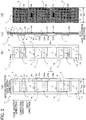
- Figs. 2(a) through 2(d) show a detailed structure of the printing tape To.
- Fig. 2(a) is a plan view showing the printing tape To in an unprinted state.
- the up-down direction in the drawing constitutes the conveying direction (also called the tape length direction and the first direction)
- the left-right direction in the drawing constitutes the tape width direction (also called the second direction)
- the near-far direction in the drawing constitutes the tape thickness direction.
- Fig. 2(b) shows a plan view of the printing tape T after the printed image R has been printed with the label-creating device 1
- Fig. 2(c) shows a cross-sectional view taken along a section I-I of the printed printing tape T
- Fig. 2(d) shows a rear view of the printed printing tape T.
- the printing tape To includes a transparent base material 21, a transparent adhesive layer 22, and a transparent release material 24 that are layered in this order from the left side to the right side in Fig. 2(c) (from the near side to the far side in Figs. 2(a) and 2(b) ) along the tape thickness direction (the depth direction when viewing Figs. 2(a), 2(b), and 2(d) and the left-right direction in Fig. 2(c) ; that is, the direction in which each layer is laminated, as will be described later).
- the base material 21, adhesive layer 22, and release material 22 may be provided with a semitransparent color.
- the release material 24 may be opaque.
- a printing surface 25 (also called a print background layer) is partially provided on the front-side (the left side in Fig. 2(c) ; hereinafter called the "first side in the thickness direction" for convenience) surface of the base material 21.
- the printing surface 25 is provided with a suitable non-transparent color and is the surface on which the thermal head 7 forms the printed image R.
- the adhesive layer 22 may be provided over part of the surface, rather than the entire surface, on the back side (the right side in Fig. 2(c) ; hereinafter called the “second side in the thickness direction” for convenience) of the base material 21, i.e., between the base material 21 and the release material 24.
- a plurality of label parts Lo (or labels L configured of printed images R formed on the label parts Lo) is arranged successively in the tape length direction (the up-down direction in the drawings) while interposed by cuts HC extending along the tape width direction.
- the base material 21 is aligned in the vertical direction in the drawings, i.e., the first direction, perpendicular to the thickness direction in correspondence with the plurality of cuts HC (in correspondence with slits S described later).
- the base material 21 is divided by half-cut-type cuts HC into a label portion LA and a non-label portion LB and is bonded via the adhesive layer 22 to the surface of the release material 24 on the first side of the thickness direction.
- each label part Lo has four areas: an adhesive area D1 (also called the first area) constituting the end portion on the upper side of the drawings along the first direction (also called the second side of the first direction), a non-adhesive area D2a (also called the second area) provided adjacent to the adhesive area D1 on the lower side in the drawings (also called the first side of the first direction), a non-adhesive area D2b (also called the second area together with the non-adhesive area D2a) provided adjacent to the non-adhesive area D2a on the lower side in the drawings, and a partial adhesive area D3 (also called the third area) provided adjacent to the non-adhesive area D2b on the lower side in the drawings.
- an adhesive area D1 also called the first area constituting the end portion on the upper side of the drawings along the first direction (also called the second side of the first direction)
- a non-adhesive area D2a also called the second area
- D2b also called
- the partial adhesive area D3 is provided with a non-adhesive area D3a (also called the first partial area) provided adjacent to the non-adhesive area D2b on the lower side in the drawings, and an adhesive area D3b (also called the second partial area) provided adjacent to the non-adhesive area D3a on the lower side in the drawings.
- a non-adhesive area D3a also called the first partial area
- an adhesive area D3b also called the second partial area
- a width Ws of the release material 24 in the second direction is greater than a width Wb of the base material 21 in the left-right direction (the second direction). Further, a thickness dimension ts of the release material 24 is smaller than a thickness dimension tb of the base material 21 and a thickness dimension tn of the adhesive layer 22.
- (half-cut) rectangular slits S (also called break lines) having substantially the same length in the second direction as the base material 21 are provided in the release material 24.
- These slits S are arranged such that the adhesive area D1 and adhesive area D3b of each slit S are positioned in a slit outer area SO outside the slit S in a plan view, while the non-adhesive area D2a, non-adhesive area D2b, and non-adhesive area D3a of each slit S are positioned in a slit inner area SI inside the slit S (a rectangular area having the same width dimension as the base material 21) in a plan view.
- the rectangular slits S are juxtaposed along the up-down direction and the printing surfaces 25 are positioned within the slit inner areas SI enclosed by the slits S in the printing tapes To and T.
- a printed image R is formed on the print background layer 25 of each label L.
- the printed images R are print objects configured of the text "A01,” “A02,” “A03,” ....
- marks PM are provided on the release material 24 in intermediate parts between two neighboring slits S for positioning control when the conveying roller 6 conveys the printing tape To. That is, the label-creating device 1 is provided with a well-known reflective optical sensor (not shown) having a light-emitting unit and a light-receiving unit. During positioning control, the optical sensor emits light from the light-emitting unit while the light-receiving unit receives light reflected off the release material 24.
- the marks PM on the release material 24 are detected based on the difference in the amount of light received between portions of the release material 24 on which the marks PM are provided and all other portions at this time, and the printing tape To is positioned based on these detections.
- marks GM are further provided on the release material 24 inside the slits S. These marks GM will be described later.
- Figs. 3(a) through 3(f) show the process for separating each label L from the printing tape T after printing.
- Fig. 3(a) is a plan view showing a printed printing tape.
- Fig. 3(b) is a cross-sectional view of the structure shown in Fig. 3(a) taken along the section II-II.
- Fig. 3(c) is a rear-side view showing the printed printing tape.
- Fig. 3(d) is a plan view showing the state of the printed printing tape after one label has been peeled off.
- Fig. 3(e) is a cross-sectional view of the structure shown in Fig. 3(d) taken along the section III-III.
- Fig. 3(f) is a rear-side view of the printing tape after a label was peeled off.
- the width Ws of the release material 24 in the second direction is prepared larger than the width Wb of the base material 21 in the printing tapes To and T, and rectangular slits S having the same width Wb in the second direction as the base material 21 are provided in the wide release material 24.
- each label L included on the printing tape T and having a printed image R formed on the printing surface 25 as described above can be peeled off the printing tape T while the rectangular-shaped portion of the release material 24 located inside the slit S (the portion included in the slit inner area SI) is separated from the other portion of the release material 24 and remains on the adhesive layer 22 side (i.e., while the adhesive layer 22 remains covered with the rectangular-shaped portion described above), as shown in Figs. 3(a) through 3(f) .
- this peeled-off portion will simply be called the "label L" for convenience.
- a space (a window WD) is left in the strip-like release material 24 inside the rectangular slit S, as illustrated in Figs. 3(d) and 3(f) .
- Figs. 4(a) and 4(b) show a detailed structure of the label L separated from the printing tape T.
- Fig. 4(a) shows a plan view of one label L
- Fig. 4(b) shows a cross-sectional view of the structure in Fig. 4(a) taken along the section IV-IV.
- the label L is wrapped around an adherend 302 having a prescribed diameter or less and is used as a rotatable label.
- the labels L are packaged in a clear plastic bag or other packaging material as preprinted printing tapes To, printed printing tapes T, or the labels L themselves that have been separated from these printing tapes To and T.
- the packaging material is then placed in a packing box such as an outer case to be stored or distributed.
- the recommended maximum diameter is noted in the description "Can be used on a LAN cable having a maximum diameter of_ _mm," for example, on at least one of this packaging material, the packing box in which the packaging material is inserted, and an instruction manual included in the packing box together with the packaging material. This recommended maximum diameter corresponds to the prescribed diameter described above.
- the label L can be wrapped around an adherend 302 having a diameter equal to or smaller than the recommended maximum diameter.
- the label L has the base material 21, adhesive layer 22, release material 24, printing surface 25, and mark GM.
- the base material 21, adhesive layer 22, and release material 24 are layered from the front side to the rear side along the thickness direction of the label L, i.e., from the near side toward the far side along the depth direction in Fig. 4(a) or from the left side toward the right side in Fig. 4(b) along the left-right direction in Fig. 4(b) .
- the base material 21 has the printing surface 25 on the front side thereof.
- the label-creating device 1 forms the printed image R on the printing surface 25.
- the base material 21 is configured of a transparent material provided with a lower stiffness than the release material 24.
- Such a base material 21 can be formed of a transparent resin material like PET, PVC, PE, or PP, for example.
- the base material 21 may be configured with a thickness of 38 ⁇ m and a stiffness of 2.9 Gpa (Young's modulus). As described with reference to Fig. 3 , this portion of the base material 21 is separated from the remaining portion as part of the label L by means of the cuts HC.
- the adhesive layer 22 is provided on the opposite side surface of the base material 21 from the printing surface 25.
- the adhesive layer 22 possesses adhesive strength and may also be provided transparently.
- the release material 24 is bonded to the adhesive layer 22 with a portion of the adhesive layer 22 exposed.
- the release material 24 is configured of a transparent material and has a higher stiffness than the base material 21.
- This type of release material 24 is also called a separator and may be formed of glassine paper, PET, kraft paper, and the like, for example. When formed of kraft paper, the release material 24 may be configured with a thickness of 57 ⁇ m and a stiffness of 4.5 Gpa (Young's modulus). As described with reference to Fig. 3 , this portion of the release material 24 is separated as part of the label L from the remainder of the release material 24 through the slits S.
- the mark GM is used for alignment when bonding together exposed sections of the adhesive layer 22 or the exposed adhesive layer 22 with the release material 24 in order to form the label L in a loop shape. Accordingly, the mark GM is provided at a position for forming the label L in a loop shape having an inner diameter greater than the prescribed diameter. Since the release material 24, adhesive layer 22, and base material 21 are all formed transparently, the mark GM can be seen through these layers in the plan views of Figs. 2(a), 2(b) , 3(a), 3(d) , and 4(a) .
- the mark GM is arranged in a position for bonding the exposed adhesive layer 22 with the release material 24. More specifically, the mark GM is separated a prescribed distance from the bottom edge of the release material 24 after the label L has been created and is disposed below the bottom edge of the printing surface 25, i.e., in the non-adhesive area D3a, as illustrated in Fig. 4(b) .
- the mark GM is preferably provided in the non-adhesive area D3a at a position near the bottom edge of the printing surface 25.
- the adhesive area D1 (the adhesive layer 22) can be bonded with the non-adhesive area D3a (the release material 24) by wrapping the label L around the adherend 302 until the bottom edge of the adhesive area D1 (the top edge of the release material 24) is approximately aligned with the mark GM.
- a method of using this mark GM when wrapping the label L around the adherend 302 will be described later.
- the label L will be described for each functional area. That is, the label L is provided with the adhesive area D1, non-adhesive area D2a, non-adhesive area D2b, and partial adhesive area D3 (the non-adhesive area D3a and adhesive area D3b) from the second side of the first direction (the upper side in the drawing) toward the first side of the first direction (the lower side in the drawing).
- the base material 21 and adhesive layer 22 are layered in order from the first side toward the second side in the thickness direction (from the left side toward the right side in Fig. 4(b) ).
- the entire region of the adhesive area D1 is provided with an adhesive property owing to the adhesive layer 22.
- the adhesive area D1 has a length L1 in the first direction.
- the base material 21, adhesive layer 22, and release material 24 are layered in order from the first side toward the second side in the thickness direction (from the left side toward the right side in Fig. 4(b) ).
- the entire region of the non-adhesive area D2a is non-adhesive, as the adhesive property of the adhesive layer 22 is inhibited by the release material 24.
- the non-adhesive area D2a has a length L2 in the first direction.
- the printing surface 25, base material 21, adhesive layer 22, and release material 24 are layered in order from the first side toward the second side of the thickness direction (from the left side toward the right side in Fig. 4(b) ).
- the entire region of the non-adhesive area D2b is non-adhesive, as the adhesive property of the adhesive layer 22 is inhibited by the release material 24.
- the printing surface 25 provided with the printed image R is disposed in the non-adhesive area D2b adjacent to the non-adhesive area D3a.
- the printing surface 25 is prepared by applying ink (an ink coating layer) of a suitable color to the base material 21.
- the thermal head 7 forms the printed image R, which is the text "A01," on the printing surface 25.
- the non-adhesive area D2b has a length L3 in the first direction.
- the base material 21, adhesive layer 22, and release material 24 are layered in order from the first side toward the second side of the thickness direction (from the left side toward the right side in Fig. 4(b) ).
- the entire region of the non-adhesive area D3a is non-adhesive, as the adhesive property of the adhesive layer 22 is inhibited by the release material 24.
- the non-adhesive area D3a has a length L4A in the first direction.
- non-adhesive area D2a, non-adhesive area D2b, and non-adhesive area D3a are portions positioned within the slit inner area SI described above (refer to the notation in Figs. 4(a) and 4(b) ).
- the base material 21 and adhesive layer 22 are layered in order from the first side toward the second side of the thickness direction (from the left side toward the right side in Fig. 4(b) ). (A portion of the release material 24 may also be included in this region by adjusting the position of the slit S.)
- the adhesive area D3b has a length L4B in the first direction.
- the partial adhesive area D3 has a length L4 in the first direction (L4A + L4B), and at least part of the partial adhesive area D3 is an adhesive area.
- the base material 21 is provided with no particular perforations or slits (excluding the cuts HC described above), and the cross-sectional shape of this layer in the thickness direction is continuous along the first direction.
- the method of printing and attaching a label L has roughly three steps (first through third steps).
- the label L has: the base material 21; the adhesive layer 22 provided on the back surface, i.e., the first surface of the base material 21; and the release material 24 bonded to the adhesive layer 22 with a portion of the adhesive layer 22 exposed.
- the release material 24 has a higher stiffness than the base material 21.
- the label-creating device 1 is used to print the top surface, i.e., the second surface of the base material 21 constituting this label L, and specifically to print the printing surface 25. As shown in Fig.
- the printed label L is separated from the printing tape T through the cuts HC in the base material 21 and the slit S in the release material 24.
- the non-label portion LB is first separated from the printing tape T, after which the label L is separated from the printing tape T. After completing this first step, the process advances to the second step.
- Figs. 5 through 8 show a procedure for attaching the label L to the adherend 302 in the second step and the third step.
- Figs. 5(a) and 5(b) are explanatory diagrams that explain the second step through a cross section in a plane perpendicular to the axial direction of the adherend 302.
- Figs. 6(a) and 6(b) are explanatory diagrams that explain the second step through a schematic perspective view when the label L is formed in a loop shape around the adherend 302.
- Figs. 7(a) through 7(c) are explanatory diagrams that explain the third step through a cross section in a plane perpendicular to the axial direction of the adherend 302.
- Figs. 5(a) and 5(b) are explanatory diagrams that explain the second step through a cross section in a plane perpendicular to the axial direction of the adherend 302.
- Figs. 6(a) and 6(b) are explanatory diagrams that explain
- FIGS. 8(a) through 8(d) are explanatory diagrams that explain the third step with schematic perspective views showing a state in which a gap is reduced and a protruding portion is wrapped. These examples show shown cases in which the label L is attached by wrapping the label L around a cylindrical or cable-like adherend 302 having a diameter 2r.
- the label L is wrapped around the adherend 302 to form a loop shape, and exposed sections of the adhesive layer 22 or an exposed section of the adhesive layer 22 and the release material 24 are bonded together while leaving a gap between the label L and the adherend 302. More specifically, the label L has areas extending continuously in the order shown in Fig. 5(a) : adhesive area D1 ⁇ non-adhesive area D2a ⁇ non-adhesive area D2b ⁇ partial adhesive area D3.
- the adherend 302 is placed on the release material 24 side of the non-adhesive area D2a. At this time, the adherend 302 is arranged near the printed image R on the printing surface 25.
- the adhesive area D1, non-adhesive area D2a, and non-adhesive area D2b of the label L are bent into a concave shape with the release material 24 on the inside, as illustrated in Fig. 5(b) .
- the adhesive layer 22 in the adhesive area D1 is bonded to the release material 24 in the non-adhesive area D3a while aligning the upper edge of the release material 24 in Fig. 5(a) with the mark GM.
- the label L is formed into a loop shape around the adherend 302 (a cable, for example), as illustrated in Fig. 5(b) and Figs.
- the mark GM can suppress positional deviation when the adhesive layer 22 and release material 24 are bonded together.
- the label L may be first formed into a loop shape and the adherend 302 may be subsequently inserted into the loop of the label L. After completing the second step, the process advances to the third step.
- the release material 24 is folded over to reduce the gap between the release material 24 and adherend 302. More specifically, a large gap exists between the release material 24 of the label L (the inside of the loop) and the adherend 302, as shown in Figs. 7(a) and 8(a) .
- the user can gradually reduce the inner area of the loop using a finger or the like to constrict the end of the loop on the mark GM side inward from the mark GM, as shown in Fig. 8(b) .
- the user does not decrease the gap to the extent that the gap becomes nothing since the label L is to be used as a rotatable label.
- the user can easily adjust the gap between the adherend 302 and the release material 24.
- the user After reducing the gap, the user then begins laying the free portion of the label L protruding out from the loop-shaped portion over the second surface of the base material 21, that is, the printing surface 25, in the direction indicated by the arrow G, as shown in Figs. 7(b), 7(c) , 8(c), and 8(d) . That is, the remaining portion of the partial adhesive area D3 that is not used in the structure encircling the adherend 302 (the adhesive area D3b in this example) is wrapped in the direction of the arrow G indicated in Fig.
- the adhesive area D3b of the partial adhesive area D3 is then bonded to the outer circumferential portions of the non-adhesive area D2a and non-adhesive area D2b to complete attachment of the label L to the adherend 302.
- the label L is rotatably wrapped around the adherend 302 and can be used as a rotatable label.
- Fig. 9 shows a sample application of the label L described above.
- a cable for use with a switching hub that relays information over a network such as a wired LAN
- the adherend 302 will be referred to as cable 302 here.
- the switching hub 300 in Fig. 9 has eight slots 301 in each of a top row and a bottom row (a total of sixteen slots).
- plates PL indicating the ID names "A01" through “A08” are provided in sequence from the left to correspond to the eight slots 301 in the top row
- plates PL indicating the ID names "A09” through “A16” are provided in sequence from the left to correspond to the eight slots 301 in the bottom row.
- the cable 302 must be appropriately connected to the corresponding slot 301.
- the label L described above is mounted on the end of each cable 302 that is to be inserted into one of the connector slots 301, and the printed image R formed on each label L has the same content as the ID name for the slot 301 to which the cable 302 is to be connected.
- a label L printed with the same text as the ID name on the plate PL of the slot 301 to which the cable 302 is to be connected is affixed to the cable 302. This clarifies the correlations between slots 301 and cables 302 that are to be connected to the slots 301, thereby preventing incorrect wiring.
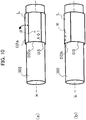
- Fig. 10 schematically shows the attached state of the label L on the cable 302.
- An axial center k of the cable 302 is also indicated in the drawing.
- the label L is affixed to the cable 302 constituting the adherend so as to be rotatable about the cable 302.
- the non-adhesive area D2b is arranged such that the printed image R of "A01" provided on the non-adhesive area D2b is facing the viewer of the drawing.
- the transparent adhesive area D3b is actually present so as to cover the outer circumferential side of the non-adhesive area D2b, the adhesive area D3b has been omitted from Fig.
- the label L can be shifted to the orientation in which the partial adhesive area D3 faces the viewer of the drawing as shown in Fig. 10(b) by rotating the label L in the direction of the dashed arrow (i.e., a circumferential direction) from the state shown in Fig. 10(a) .
- the label L is rotatable. Accordingly, by rotating the label L in the direction opposite that described above to the position shown in Fig. 10(a) , the printed image R can be made visible.
- the label L according to the present embodiment is used by forming the label L in a loop shape that is wrapped around the adherend 302. That is, the user first forms the label L in a loop shape by bonding together exposed sections of the adhesive layer 22 or an exposed section of the adhesive layer 22 and the release material 24.
- the mark GM is provided on the label L for alignment when forming this loop shape. Further, this mark GM is provided at a position such that the inner diameter of the loop shape formed in the label L is greater than the outer diameter of the adherend 302 (the prescribed diameter).
- the user reduces the gap between the adherend 302 and the label L while wrapping the free portion of the label L protruding out from the loop-shaped portion over the printing surface 25 of the base material 21 and attaching the label L to the adherend 302.
- the label can be suppressed from being wrapped tightly relative to the adherend 24 since the release material 24 having greater stiffness than the base material 21 must be folded over.
- the mark GM is also disposed at a position for bonding the exposed section of the adhesive layer 22 with the release material 24.
- the mark GM for alignment when bonding the exposed section of the adhesive layer 22 with the release material 24 to form the label L into a loop shape, a gap can always be formed between the adhesive layer 22 and the label.
- the labels L are packaged in a packaging material.
- the prescribed diameter is a recommended maximum diameter that is noted on this packaging material, or on the packing box in which the packaging material is included, or in an instruction manual included in the packing box together with the packaging material. Accordingly, labels can be prevented from being difficult to rotate about an adherend when wrapped around an adherend having the recommended maximum diameter for usage noted on the packaging material, on the packing box, or in the instruction manual.
- the base material 21 and adhesive layer 22 are provided with a transparent or semitransparent color. Therefore, when the label L is formed into a loop shape and the free portion of the label L protruding out from the loop-shaped portion is subsequently wrapped so as to cover the printing surface 25, the content of the printed image R on the printing surface 25 can be seen through the base material 21 and adhesive layer 22 covering the printing surface 25.
- the mark GM is formed on the release material 24, as shown in Fig. 4(b) .
- the adhesive layer 22 the adhesive area D1
- the release material 24 the non-adhesive area D3a
- the position in which the mark GM is formed is not limited to this example.
- the mark GM may be formed on the base material 21, and the edge of the base material 21 may be aligned with the mark GM when bonding. This first variation will be described below.
- Figs. 11(a) and 11(b) show a detailed structure of the label L that has been separated from the printing tape T according to the first variation.
- Fig. 11(a) is a plan view of a single label L
- Fig. 11(b) is a cross-sectional view of the structure in Fig. 11(a) taken along the section V-V.
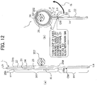
- Figs. 12(a) and 12(b) are explanatory diagrams that explain the second step according to the first variation through a cross section in a plane perpendicular to the axial direction of the adherend 302.
- Figs. 11 and 12 correspond to Figs. 4 and 5 in the first embodiment.
- the printing surface 25 is formed at approximately the same length as the release material 24 in the tape length direction (the first direction), and the mark GM is formed on the base material 21, as illustrated in Fig. 11(b) .
- the mark GM may be disposed below a bottom edge 25a of the printing surface 25 and arranged closer to the bottom edge 25a side than a bottom edge La of the label L.
- the distance from this bottom edge to the mark GM may be set approximately the same as the distance from a top edge 25b of the printing surface 25 to a top edge Lb of the label L.
- the adhesive layer 22 in the adhesive area D1 may be bonded with the adhesive layer 22 in an adhesive area D4 by wrapping the label L around the adherend 302 such that the top edge Lb of the label L is approximately aligned with the mark GM.
- a method of using this mark GM when wrapping the label L around the adherend 302 will be described later.
- the label L according to this variation will be described for each functional area. That is, the label L is provided with the adhesive area D1, a non-adhesive area D23, and an adhesive area D4 from the second side of the first direction (the upper side in the drawing) toward the first side of the first direction (the lower side in the drawing).
- the non-adhesive area D23 corresponds to the non-adhesive areas D2a and D2b and the non-adhesive area D3a of the first embodiment and the adhesive area D4 corresponds to the adhesive area D3b of the first embodiment.
- the printing surface 25 is arranged only in the non-adhesive area D2b in the first embodiment, the printing surface 25 is arranged throughout the entire non-adhesive area D23 in the present variation.
- the method of printing and attaching a label L according to this first variation differs from that in the first embodiment primarily in the second step. Therefore, the second step will be described here.
- the label L in the present variation has areas extending continuously in the order shown in Fig. 12(a) : adhesive area D1 ⁇ non-adhesive area D23 ⁇ adhesive area D4.
- the adherend 302 is first placed on the release material 24 side of the non-adhesive area D23. At this time, the adherend 302 is arranged near the printed image R on the printing surface 25.
- the adhesive area D1 and non-adhesive area D23 of the label L are bent into a concave shape with the release material 24 on the inside, as illustrated in Fig. 12(b) .
- the adhesive layer 22 in the adhesive area D1 is bonded to the adhesive layer 22 in the adhesive area D4 while aligning the top edge Lb of the label L in Fig. 12(a) with the mark GM.
- the label L is formed into a loop shape around the adherend 302 (a cable, for example), as illustrated in Fig. 12(b) .
- the mark GM can suppress positional deviation between the adhesive layers 22 when the adhesive layers 22 are bonded together.
- the label L may be first formed into a loop shape, and the adherend 302 may be subsequently inserted into the loop formed in the label L.
- the process advances to the third step.
- the release material 24 is folded over to reduce the gap between the label L and the adherend 302, and the attachment of the label L to the adherend 302 is completed by wrapping the free portion of the label L protruding out from the loop-shaped portion in the direction of the arrow G so as to cover the second surface of the base material 21, i.e., the printing surface 25.
- the label L is rotatably wrapped around the adherend 302 and can be used as a rotatable label.
- the label L according to the first variation described above can obtain the same operations and effects as the first embodiment.
- the base material 21 is provided with no perforations or slits other than the cuts HC, but the present invention is not limited to such cases.
- the base material 21 may be provided with a hole or a series of holes.
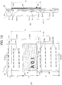
- Figs. 13(a) and 13(b) show a detailed structure of the label L according to a second variation after the label L has been separated from the printing tape T.
- Fig. 13(a) is a plan view of a single label L.
- Fig. 13(b) is a cross-sectional view of the structure in Fig. 13(a) taken along the section V-V.
- Fig. 13 corresponds to Fig. 4 in the first embodiment.
- perforations MH comprising a series of holes are formed in the base material 21, as shown in Figs. 13(a) and 13(b) .
- the perforations MH are formed along the tape width direction (the second direction) and a plurality of rows of perforations are juxtaposed in parallel in the tape length direction (the first direction). Since the stiffness of the base material 21 is weakened, making the stiffness of the release material 24 relatively stronger, the label L according to this variation can suppress the label L from becoming tightly wrapped about the adherend 302.
- the perforations MH may also be configured of a single hole or a combination of a single hole and a series of holes.
- Figs. 14(a) through 14(f) show the process of separating each label L according to this variation from the printing tape T after printing.
- Fig. 14(a) is a plan view showing the printed printing tape.
- Fig. 14(b) is a cross-sectional view of the structure in Fig. 14(a) taken along the section VII-VII. Fig.
- FIG. 14(c) is a rear view of the printed printing tape.
- Fig. 14(d) is a plan view showing a single label that has been peeled off the printed printing tape.
- Fig. 14(e) is a cross-sectional view of the structure in Fig. 14(d) taken along the section VIII-VIII.
- Fig. 14(f) is a rear view of the printing tape after the label has been peeled off.
- Fig. 14 corresponds to Fig. 3 in the first embodiment.
- the slit S in the label L has a shape that includes a horseshoe shape combined on the bottom of the rectangular slit S in Fig. 3 relative to the tape length direction.
- both edges in the tape width direction extend to a position corresponding to the label L, that is, the cut HC, while the center in the tape width direction has an inverted U-shape.
- the release material 24 is arranged in the adhesive area D3b according to the slit S so as to have a portion on the non-adhesive area D3a side and portions on both sides in the tape width direction (the left and right sides in the drawing), as illustrated in Figs. 14(d) through 14(f) .
- the portion of the release material 24 in which the positioning mark PM is located remains on the printing tape T side.
- the label L has a mark GM for alignment when wrapping the label L around the adherend 302, and a separate mark PM for positioning when conveying the printing tape To, but the present invention is not limited to this example.
- the mark GM may also take on the positioning function of the mark PM.
- Figs. 15(a) through 15(f) show the process of separating a label L from a printing tape T after printing according to this variation.
- Fig. 15(a) is a plan view showing the printed printing tape.
- Fig. 15(b) is a cross-sectional view of the structure in Fig. 15(a) taken along the section IX-IX.
- Fig. 15(c) is a rear view showing the printed printing tape.
- FIG. 15(d) is a plan view showing a single label that has been peeled off the printed printing tape.
- Fig. 15(e) is a cross-sectional view of the structure shown in Fig. 15(d) taken along the section X-X.
- Fig. 15(f) is a rear view of the printing tape after the label has been peeled off.
- Fig. 15 corresponds to Fig. 3 in the first embodiment.
- a mark GM alone is arranged in the label L according to this variation, as shown in Fig. 15 .
- the mark GM is formed with the same shape, format, and the like as the mark PM according to the first embodiment so that the positioning mechanism of the label-creating device 1 can recognize or detect the mark GM. Accordingly, the mark GM can serve as the positioning mark PM during conveyance in order to execute a print on the printing surface 25.
- positioning marks PM do not need to be provided separately for positioning during conveyance when printing on the printing surfaces 25.
- labels L in the first embodiment described above have marks GM for alignment
- the present invention is not limited to this example.
- the label L may have a special shape for alignment.
- Figs. 15 and 16 show an example of this special shape.
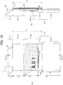
- Figs. 16(a) and 16(b) show a detailed structure of the label L according to the fourth variation after being separated from the printing tape T.
- Fig. 16(a) is a plan view of a single label L.
- Fig. 16(b) is a cross-sectional view of the structure in Fig. 16(a) taken along the section IX-IX.
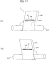
- Figs. 17(a) and 17(b) are schematic perspective views showing the label L formed into a loop shape around the adherend 302 through the second step.
- Figs. 16 and 17 correspond to Figs. 4 and 6 in the first embodiment.
- the label L according to the present variation has a guide slit GS and a guide tab GT as an example of the special shape for alignment in place of the mark GM.
- the guide slit GS is an example of the cut-out part and is used for alignment together with the guide tab GT described later when bonding together two exposed sections of the adhesive layer 22 or an exposed section of the adhesive layer 22 and the release material 24 in order to form the label L into a loop shape. Accordingly, the guide slit GS is provided at a position for forming the label into a loop shape having an inner diameter greater than the prescribed diameter. As shown in Figs. 16(a) and 16(b) , the guide slit GS is formed in a slit shape arranged longitudinally in the tape width direction. The guide slit GS penetrates the release material 24, adhesive layer 22, and base material 21.
- the guide slit GS is separated a prescribed distance from the bottom edge of the release material 24 after the label L is formed and provided below the bottom edge of the printing surface 25, i.e., in the non-adhesive area D3a, as illustrated in Fig. 16(b) .
- the guide slit GS is preferably provided in the non-adhesive area D3a at a position near the bottom edge of the printing surface 25.
- the guide slit GS is formed as a through-hole, but the guide slit GS may be formed as a slit having a prescribed depth sufficient for inserting the guide tab GT described later.
- the guide tab GT is an example of the insertion part and is inserted into the guide slit GS described above when forming the label L into a loop shape. Accordingly, the guide tab GT is provided on the upper edge of the label L. More specifically, the guide tab GT is provided in the adhesive area D1, as shown in Fig. 16(a) . In order to be insertable into the guide slit GS, the guide tab GT is formed in a position corresponding to the guide slit GS in the tape width direction and has a length equal to or smaller than the length of the guide slit GS in the tape width direction. Further, since the top edge of the guide tab GT shown in Fig.
- the guide tab GT is preferably shaped so that its length in the tape width direction increases downward from the top edge of the label L, as shown in Fig. 16(a) , in order to facilitate insertion.
- the label L in the first embodiment is positioned by aligning the upper edge of the release material 24 with the mark GM, as shown in Fig. 6(a) and other drawings.
- the label L in this variation is positioned by inserting the guide tab GT into the guide slit GS from the back side (the side of the release material 24), as shown in Fig. 17(a) .
- the guide tab GT is inserted into the guide slit GS formed in the non-adhesive area D3a from the near side shown in Fig. 17(b) (the side with the release material 24) toward the far side (the side with the base material 21).
- the method for printing the label L is identical to that in the first embodiment and will not be described here.
- the label L of the present variation described above even users unfamiliar with the operation can always form a gap between the adherend 302 and the label L by aligning the guide slit GS and guide tab GT constituting the special shape to form the loop shape described above. Hence, at the stage of forming this loop shape, the label does not become too tight around the adherend 302. Since the release material 24 having a higher stiffness than the base material 21 must be subsequently folded over when wrapping the free portion of the label L protruding out from the loop-shaped portion so as to cover the printing surface of the base material 21, the label L is prevented from being wrapped too tightly around the adherend 21.
- the label L is prevented from becoming difficult to rotate relative to the adherend 302. Further, by forming the loop shape while aligning the guide slit GS and the guide tab GT, a gap can always be produced between the adherend 302 and the label L.
Landscapes
- Physics & Mathematics (AREA)
- General Physics & Mathematics (AREA)
- Engineering & Computer Science (AREA)
- Theoretical Computer Science (AREA)
- Electric Cable Installation (AREA)
- Making Paper Articles (AREA)
Abstract
Description
- The present invention relates to a label and a method of printing and attaching a label.
- A label known in the art is fitted around a cylindrical adherend such as a cable, for example. The label in this conventional technology is provided with a layered structure including a base material, an adhesive layer, and a release material and is used by wrapping the label around an adherend to form a loop shape. Here, the user forms the label into a loop shape by bonding an exposed section of the adhesive layer with the release material or adhesive layer. In the conventional technology described above, bonding is carried out so that the inner diameter of the loop-shaped portion is approximately equivalent to the outer diameter of the adherend. Owing to the release material contacting the adherend, the label does not adhere to the adherend and is used as a rotating label.
- [PTL 1]
Japanese Patent Application Publication No. 2018-172607 - However, a user unfamiliar with this operation might leave no gap between the adherend and label when forming the label into the loop shape, making the label too tight around the adherend so that the label cannot rotate.
- It is an object of the present invention to provide a label whose rotation relative to an adherend is unlikely to be impeded.
- In order to provide the above and other objects, the present invention provides a label to be wrapped around an adherend after being printed. The adherend has a diameter equal to or smaller than a prescribed diameter. The label includes: a base material; an adhesive layer; a release material; and a mark for alignment. The base material has a printing surface. The adhesive layer is provided on an opposite side surface of the base material from the printing surface. The release material is bonded to the adhesive layer with a portion of the adhesive layer exposed. The release material has a higher stiffness than the base material. The mark for alignment is to be used when bonding together exposed sections of the adhesive layer or an exposed section of the adhesive layer with the release material in order to form the label into a loop shape. The mark is provided at a position for forming the label in the loop shape having an inner diameter greater than the prescribed diameter.
- The label according to the present invention is used by forming the label in a loop shape that is wrapped around the adherend. That is, the user first forms the label into a loop shape by bonding together exposed sections of the adhesive layer or an exposed section of the adhesive layer and the release material. The mark is provided on the label according to the present invention for alignment when forming this loop shape. Further, this mark is provided at a position such that the inner diameter of the loop shape formed in the label is greater than the outer diameter of the adherend (the prescribed diameter). By using the mark for alignment to form the loop shape in this way, even users unfamiliar with the operation can always ensure a gap is formed between the adherend and the label. Hence, at the stage of forming this loop shape, the label can be prevented from becoming too tight around the adherend.
- After the label is formed in a loop shape as described above, the user reduces the gap between the adherend and the label while wrapping the free portion of the label protruding out from the loop-shaped portion to cover the printing surface of the base material and attaching the label to the adherend. Here, the label can be suppressed from being wrapped tightly relative to the adherend since the release material having greater stiffness than the base material must be folded over.
- When the label is ultimately attached to the adherend as a result of the above operations, a gap can be secured between the label and the adherend, thereby preventing the label from becoming difficult to rotate relative to the adherend.
- According to the present invention, rotation relative to an adherend is unlikely to be impeded.
-
- [
Fig. 1 ]
Fig. 1 is an explanatory diagram showing a schematic configuration of a label-creating device according to a first embodiment of the present invention. - [
Fig. 2 ]
Fig. 2 is an explanatory diagram showing a detailed structure of a printing tape. - [
Fig. 3 ]
Fig. 3 is an explanatory diagram showing a process for separating each label from the printed printing tape. - [
Fig. 4 ]
Fig. 4 is an explanatory diagram showing a detailed structure of the label separated from the printing tape. - [
Fig. 5 ]
Fig. 5 is an explanatory diagram showing a procedure for attaching the label to an adherend. - [
Fig. 6 ]
Fig. 6 is an explanatory diagram showing the procedure for attaching the label to the adherend. - [
Fig. 7 ]
Fig. 7 is an explanatory diagram showing the procedure for attaching the label to the adherend. - [
Fig. 8 ]
Fig. 8 is an explanatory diagram showing the procedure for attaching the label to the adherend. - [
Fig. 9 ]
Fig. 9 is a perspective view showing a sample application of the label. - [
Fig. 10 ]
Fig. 10 is a schematic diagram showing an attached state of the label on a cable. - [
Fig. 11 ]
Fig. 11 is an explanatory diagram showing a detailed structure of a label separated from a printing tape according to a first variation. - [
Fig. 12 ]
Fig. 12 is an explanatory diagram showing a procedure for attaching the label to an adherend according to the first variation. - [
Fig. 13 ]
Fig. 13 is an explanatory diagram showing a detailed structure of a label separated from a printing tape according to a second variation. - [
Fig. 14 ]
Fig. 14 is an explanatory diagram showing a process for separating each label from a printed printing tape according to a third variation. - [
Fig. 15 ]
Fig. 15 is an explanatory diagram showing a process for separating each label from a printed printing tape according to a fourth variation. - [
Fig. 16 ]
Fig. 16 is an explanatory diagram showing a detailed structure of a label separated from a printing tape according to a fifth variation. - [
Fig. 17 ]
Fig. 17 is an explanatory diagram showing a procedure for attaching the label to an adherend according to the fifth variation. - Below, one embodiment of the present invention will be described in detail while referring to the accompanying drawings. In general, components having essentially the same functions are designated with the same reference numerals in the following specification and the drawings. Duplicate descriptions of such components are omitted accordingly.
- First, the functional configuration of a label-creating device according to a first embodiment of the present invention will be described with reference to
Fig. 1 . - In
Fig. 1 , a label-creating device 1 (also called a printing device) has acontrol circuit 2, anoperation unit 3 on which a user (also called an operator) can perform desired operations, adisplay unit 4 for displaying prescribed information, aRAM 5 for storing various types of information, a conveying roller 6 (also called a conveying unit), a print head 7 (also called a printing unit), a cuttinglever 8, and acutter 9. - A
cartridge holder 12 is provided in the label-creatingdevice 1. Atape cartridge 10 is detachably mounted in thecartridge holder 12. Thetape cartridge 10 has ahousing 11 that accommodates atape roll 10A (depicted as concentric circles for simplification, but actually wound into a roll). A printing tape To (also called a tape and a long medium) is wound into thetape roll 10A. Here, thetape cartridge 10 may be a die-cut label type or a continuous length type. In the die-cut label type, a printing tape To having cuts HC (described later with reference toFig. 2 ) formed by half-cutting the printing tape To is wound about the tape roll A. In the continuous length type, a printing tape To having no cuts HC is wound about the tape roll A. Either type oftape cartridge 10 can be used in the label-creatingdevice 1. Unless otherwise stated, the following example describes a case of using the die-cut labeltype tape cartridge 10. - The
control circuit 2 is provided with a CPU and a ROM not shown in the drawings. Thecontrol circuit 2 executes various programs pre-stored in the ROM while utilizing the temporary storage function of theRAM 5 in order to perform overall control of the label-creatingdevice 1. - The conveying roller 6 is disposed in opposition to the
print head 7. The printing tape To paid out from thetape roll 10A is interposed between the conveying roller 6 andprint head 7. By rotating, the conveying roller 6 conveys the printing tape To while pulling the printing tape To from thetape roll 10A. - The
print head 7 prints desired print objects (see printed images R described later) on individual label parts (described later in greater detail) of the printing tape To conveyed by the conveying roller 6. The print objects are user-specified characters, icons, and the like. - When actuated through a user operation on the cutting
lever 8, thecutter 9 cuts off a printed section of a printing tape T (described later in greater detail) having a plurality of labels L formed along the conveying direction. -
Figs. 2(a) through 2(d) show a detailed structure of the printing tape To.Fig. 2(a) is a plan view showing the printing tape To in an unprinted state. The up-down direction in the drawing constitutes the conveying direction (also called the tape length direction and the first direction), the left-right direction in the drawing constitutes the tape width direction (also called the second direction), and the near-far direction in the drawing constitutes the tape thickness direction. Further,Fig. 2(b) shows a plan view of the printing tape T after the printed image R has been printed with the label-creatingdevice 1,Fig. 2(c) shows a cross-sectional view taken along a section I-I of the printed printing tape T, andFig. 2(d) shows a rear view of the printed printing tape T. - As shown in
Figs. 2(a) through 2(d) , the printing tape To includes atransparent base material 21, a transparentadhesive layer 22, and atransparent release material 24 that are layered in this order from the left side to the right side inFig. 2(c) (from the near side to the far side inFigs. 2(a) and 2(b) ) along the tape thickness direction (the depth direction when viewingFigs. 2(a), 2(b), and 2(d) and the left-right direction inFig. 2(c) ; that is, the direction in which each layer is laminated, as will be described later). Note that all of thebase material 21,adhesive layer 22, andrelease material 22 may be provided with a semitransparent color. Further, therelease material 24 may be opaque. - At this time, a printing surface 25 (also called a print background layer) is partially provided on the front-side (the left side in
Fig. 2(c) ; hereinafter called the "first side in the thickness direction" for convenience) surface of thebase material 21. Theprinting surface 25 is provided with a suitable non-transparent color and is the surface on which thethermal head 7 forms the printed image R. Note that theadhesive layer 22 may be provided over part of the surface, rather than the entire surface, on the back side (the right side inFig. 2(c) ; hereinafter called the "second side in the thickness direction" for convenience) of thebase material 21, i.e., between thebase material 21 and therelease material 24. - In the printing tapes To and T having the layered structure described above, a plurality of label parts Lo (or labels L configured of printed images R formed on the label parts Lo) is arranged successively in the tape length direction (the up-down direction in the drawings) while interposed by cuts HC extending along the tape width direction. The
base material 21 is aligned in the vertical direction in the drawings, i.e., the first direction, perpendicular to the thickness direction in correspondence with the plurality of cuts HC (in correspondence with slits S described later). In other words, thebase material 21 is divided by half-cut-type cuts HC into a label portion LA and a non-label portion LB and is bonded via theadhesive layer 22 to the surface of therelease material 24 on the first side of the thickness direction. - Owing to the layered structure described above, each label part Lo has four areas: an adhesive area D1 (also called the first area) constituting the end portion on the upper side of the drawings along the first direction (also called the second side of the first direction), a non-adhesive area D2a (also called the second area) provided adjacent to the adhesive area D1 on the lower side in the drawings (also called the first side of the first direction), a non-adhesive area D2b (also called the second area together with the non-adhesive area D2a) provided adjacent to the non-adhesive area D2a on the lower side in the drawings, and a partial adhesive area D3 (also called the third area) provided adjacent to the non-adhesive area D2b on the lower side in the drawings. The partial adhesive area D3 is provided with a non-adhesive area D3a (also called the first partial area) provided adjacent to the non-adhesive area D2b on the lower side in the drawings, and an adhesive area D3b (also called the second partial area) provided adjacent to the non-adhesive area D3a on the lower side in the drawings.
- At this time, a width Ws of the
release material 24 in the second direction is greater than a width Wb of thebase material 21 in the left-right direction (the second direction). Further, a thickness dimension ts of therelease material 24 is smaller than a thickness dimension tb of thebase material 21 and a thickness dimension tn of theadhesive layer 22. - As shown in
Fig. 2(d) , (half-cut) rectangular slits S (also called break lines) having substantially the same length in the second direction as thebase material 21 are provided in therelease material 24. These slits S are arranged such that the adhesive area D1 and adhesive area D3b of each slit S are positioned in a slit outer area SO outside the slit S in a plan view, while the non-adhesive area D2a, non-adhesive area D2b, and non-adhesive area D3a of each slit S are positioned in a slit inner area SI inside the slit S (a rectangular area having the same width dimension as the base material 21) in a plan view. As a result, the rectangular slits S are juxtaposed along the up-down direction and the printing surfaces 25 are positioned within the slit inner areas SI enclosed by the slits S in the printing tapes To and T. A printed image R is formed on theprint background layer 25 of each label L. In this example, the printed images R are print objects configured of the text "A01," "A02," "A03," .... - As shown in
Fig. 2(d) , marks PM are provided on therelease material 24 in intermediate parts between two neighboring slits S for positioning control when the conveying roller 6 conveys the printing tape To. That is, the label-creatingdevice 1 is provided with a well-known reflective optical sensor (not shown) having a light-emitting unit and a light-receiving unit. During positioning control, the optical sensor emits light from the light-emitting unit while the light-receiving unit receives light reflected off therelease material 24. The marks PM on therelease material 24 are detected based on the difference in the amount of light received between portions of therelease material 24 on which the marks PM are provided and all other portions at this time, and the printing tape To is positioned based on these detections. As shown inFig. 2(d) , marks GM are further provided on therelease material 24 inside the slits S. These marks GM will be described later. -
Figs. 3(a) through 3(f) show the process for separating each label L from the printing tape T after printing.Fig. 3(a) is a plan view showing a printed printing tape.Fig. 3(b) is a cross-sectional view of the structure shown inFig. 3(a) taken along the section II-II.Fig. 3(c) is a rear-side view showing the printed printing tape.Fig. 3(d) is a plan view showing the state of the printed printing tape after one label has been peeled off.Fig. 3(e) is a cross-sectional view of the structure shown inFig. 3(d) taken along the section III-III.Fig. 3(f) is a rear-side view of the printing tape after a label was peeled off. - As described above, the width Ws of the
release material 24 in the second direction is prepared larger than the width Wb of thebase material 21 in the printing tapes To and T, and rectangular slits S having the same width Wb in the second direction as thebase material 21 are provided in thewide release material 24. Owing to these slits S, each label L included on the printing tape T and having a printed image R formed on theprinting surface 25 as described above can be peeled off the printing tape T while the rectangular-shaped portion of therelease material 24 located inside the slit S (the portion included in the slit inner area SI) is separated from the other portion of therelease material 24 and remains on theadhesive layer 22 side (i.e., while theadhesive layer 22 remains covered with the rectangular-shaped portion described above), as shown inFigs. 3(a) through 3(f) . In the following description, this peeled-off portion will simply be called the "label L" for convenience. After the label L has been peeled off, a space (a window WD) is left in the strip-like release material 24 inside the rectangular slit S, as illustrated inFigs. 3(d) and 3(f) . -
Figs. 4(a) and 4(b) show a detailed structure of the label L separated from the printing tape T.Fig. 4(a) shows a plan view of one label L, andFig. 4(b) shows a cross-sectional view of the structure inFig. 4(a) taken along the section IV-IV. - Once printed, the label L is wrapped around an
adherend 302 having a prescribed diameter or less and is used as a rotatable label. The labels L are packaged in a clear plastic bag or other packaging material as preprinted printing tapes To, printed printing tapes T, or the labels L themselves that have been separated from these printing tapes To and T. The packaging material is then placed in a packing box such as an outer case to be stored or distributed. The recommended maximum diameter is noted in the description "Can be used on a LAN cable having a maximum diameter of_ _mm," for example, on at least one of this packaging material, the packing box in which the packaging material is inserted, and an instruction manual included in the packing box together with the packaging material. This recommended maximum diameter corresponds to the prescribed diameter described above. Thus, the label L can be wrapped around anadherend 302 having a diameter equal to or smaller than the recommended maximum diameter. - As shown in
Figs. 4(a) and 4(b) , the label L has thebase material 21,adhesive layer 22,release material 24,printing surface 25, and mark GM. Thebase material 21,adhesive layer 22, andrelease material 24 are layered from the front side to the rear side along the thickness direction of the label L, i.e., from the near side toward the far side along the depth direction inFig. 4(a) or from the left side toward the right side inFig. 4(b) along the left-right direction inFig. 4(b) . - The
base material 21 has theprinting surface 25 on the front side thereof. The label-creatingdevice 1 forms the printed image R on theprinting surface 25. Thebase material 21 is configured of a transparent material provided with a lower stiffness than therelease material 24. Such abase material 21 can be formed of a transparent resin material like PET, PVC, PE, or PP, for example. When formed of PET, for example, thebase material 21 may be configured with a thickness of 38 µm and a stiffness of 2.9 Gpa (Young's modulus). As described with reference toFig. 3 , this portion of thebase material 21 is separated from the remaining portion as part of the label L by means of the cuts HC. - The
adhesive layer 22 is provided on the opposite side surface of thebase material 21 from theprinting surface 25. Theadhesive layer 22 possesses adhesive strength and may also be provided transparently. - The
release material 24 is bonded to theadhesive layer 22 with a portion of theadhesive layer 22 exposed. Therelease material 24 is configured of a transparent material and has a higher stiffness than thebase material 21. This type ofrelease material 24 is also called a separator and may be formed of glassine paper, PET, kraft paper, and the like, for example. When formed of kraft paper, therelease material 24 may be configured with a thickness of 57 µm and a stiffness of 4.5 Gpa (Young's modulus). As described with reference toFig. 3 , this portion of therelease material 24 is separated as part of the label L from the remainder of therelease material 24 through the slits S. - The mark GM is used for alignment when bonding together exposed sections of the
adhesive layer 22 or the exposedadhesive layer 22 with therelease material 24 in order to form the label L in a loop shape. Accordingly, the mark GM is provided at a position for forming the label L in a loop shape having an inner diameter greater than the prescribed diameter. Since therelease material 24,adhesive layer 22, andbase material 21 are all formed transparently, the mark GM can be seen through these layers in the plan views ofFigs. 2(a), 2(b) ,3(a), 3(d) , and4(a) . - In the present embodiment, the mark GM is arranged in a position for bonding the exposed
adhesive layer 22 with therelease material 24. More specifically, the mark GM is separated a prescribed distance from the bottom edge of therelease material 24 after the label L has been created and is disposed below the bottom edge of theprinting surface 25, i.e., in the non-adhesive area D3a, as illustrated inFig. 4(b) . The mark GM is preferably provided in the non-adhesive area D3a at a position near the bottom edge of theprinting surface 25. As a result, the adhesive area D1 (the adhesive layer 22) can be bonded with the non-adhesive area D3a (the release material 24) by wrapping the label L around theadherend 302 until the bottom edge of the adhesive area D1 (the top edge of the release material 24) is approximately aligned with the mark GM. A method of using this mark GM when wrapping the label L around theadherend 302 will be described later. - The label L will be described for each functional area. That is, the label L is provided with the adhesive area D1, non-adhesive area D2a, non-adhesive area D2b, and partial adhesive area D3 (the non-adhesive area D3a and adhesive area D3b) from the second side of the first direction (the upper side in the drawing) toward the first side of the first direction (the lower side in the drawing).
- In the adhesive area D1, the
base material 21 andadhesive layer 22 are layered in order from the first side toward the second side in the thickness direction (from the left side toward the right side inFig. 4(b) ). Thus, the entire region of the adhesive area D1 is provided with an adhesive property owing to theadhesive layer 22. Note that the adhesive area D1 has a length L1 in the first direction. - In the non-adhesive area D2a, the
base material 21,adhesive layer 22, andrelease material 24 are layered in order from the first side toward the second side in the thickness direction (from the left side toward the right side inFig. 4(b) ). Thus, the entire region of the non-adhesive area D2a is non-adhesive, as the adhesive property of theadhesive layer 22 is inhibited by therelease material 24. The non-adhesive area D2a has a length L2 in the first direction. - In the non-adhesive area D2b, the
printing surface 25,base material 21,adhesive layer 22, andrelease material 24 are layered in order from the first side toward the second side of the thickness direction (from the left side toward the right side inFig. 4(b) ). Thus, the entire region of the non-adhesive area D2b is non-adhesive, as the adhesive property of theadhesive layer 22 is inhibited by therelease material 24. At this time, theprinting surface 25 provided with the printed image R is disposed in the non-adhesive area D2b adjacent to the non-adhesive area D3a. In this example, theprinting surface 25 is prepared by applying ink (an ink coating layer) of a suitable color to thebase material 21. As has been described, thethermal head 7 forms the printed image R, which is the text "A01," on theprinting surface 25. The non-adhesive area D2b has a length L3 in the first direction. - In the non-adhesive area D3a of the partial adhesive area D3, the
base material 21,adhesive layer 22, andrelease material 24 are layered in order from the first side toward the second side of the thickness direction (from the left side toward the right side inFig. 4(b) ). Thus, the entire region of the non-adhesive area D3a is non-adhesive, as the adhesive property of theadhesive layer 22 is inhibited by therelease material 24. The non-adhesive area D3a has a length L4A in the first direction. - Note that the non-adhesive area D2a, non-adhesive area D2b, and non-adhesive area D3a are portions positioned within the slit inner area SI described above (refer to the notation in
Figs. 4(a) and 4(b) ). - In the adhesive area D3b of the partial adhesive area D3, the
base material 21 andadhesive layer 22 are layered in order from the first side toward the second side of the thickness direction (from the left side toward the right side inFig. 4(b) ). (A portion of therelease material 24 may also be included in this region by adjusting the position of the slit S.) Thus, the entire region or at least part of the region of the adhesive area D3b is provided with an adhesive property through theadhesive layer 22. The adhesive area D3b has a length L4B in the first direction. As a result, the partial adhesive area D3 has a length L4 in the first direction (L4A + L4B), and at least part of the partial adhesive area D3 is an adhesive area. - The
base material 21 is provided with no particular perforations or slits (excluding the cuts HC described above), and the cross-sectional shape of this layer in the thickness direction is continuous along the first direction. - Here, a method of printing and attaching a label L will be described. The method of printing and attaching a label L has roughly three steps (first through third steps). As described above, the label L has: the
base material 21; theadhesive layer 22 provided on the back surface, i.e., the first surface of thebase material 21; and therelease material 24 bonded to theadhesive layer 22 with a portion of theadhesive layer 22 exposed. Therelease material 24 has a higher stiffness than thebase material 21. In the first step, the label-creatingdevice 1 is used to print the top surface, i.e., the second surface of thebase material 21 constituting this label L, and specifically to print theprinting surface 25. As shown inFig. 3 and other drawings, the printed label L is separated from the printing tape T through the cuts HC in thebase material 21 and the slit S in therelease material 24. As shown inFig. 3(d) , the non-label portion LB is first separated from the printing tape T, after which the label L is separated from the printing tape T. After completing this first step, the process advances to the second step. -
Figs. 5 through 8 show a procedure for attaching the label L to theadherend 302 in the second step and the third step.Figs. 5(a) and 5(b) are explanatory diagrams that explain the second step through a cross section in a plane perpendicular to the axial direction of theadherend 302.Figs. 6(a) and 6(b) are explanatory diagrams that explain the second step through a schematic perspective view when the label L is formed in a loop shape around theadherend 302.Figs. 7(a) through 7(c) are explanatory diagrams that explain the third step through a cross section in a plane perpendicular to the axial direction of theadherend 302.Figs. 8(a) through 8(d) are explanatory diagrams that explain the third step with schematic perspective views showing a state in which a gap is reduced and a protruding portion is wrapped. These examples show shown cases in which the label L is attached by wrapping the label L around a cylindrical or cable-like adherend 302 having a diameter 2r. - In the second step, the label L is wrapped around the
adherend 302 to form a loop shape, and exposed sections of theadhesive layer 22 or an exposed section of theadhesive layer 22 and therelease material 24 are bonded together while leaving a gap between the label L and theadherend 302. More specifically, the label L has areas extending continuously in the order shown inFig. 5(a) : adhesive area D1 → non-adhesive area D2a → non-adhesive area D2b → partial adhesive area D3. First, theadherend 302 is placed on therelease material 24 side of the non-adhesive area D2a. At this time, theadherend 302 is arranged near the printed image R on theprinting surface 25. Next, the adhesive area D1, non-adhesive area D2a, and non-adhesive area D2b of the label L are bent into a concave shape with therelease material 24 on the inside, as illustrated inFig. 5(b) . As shown inFigs. 5(b) and6(a) through8(a) , theadhesive layer 22 in the adhesive area D1 is bonded to therelease material 24 in the non-adhesive area D3a while aligning the upper edge of therelease material 24 inFig. 5(a) with the mark GM. Through this action, the label L is formed into a loop shape around the adherend 302 (a cable, for example), as illustrated inFig. 5(b) andFigs. 6(a) through8(a) . In the present embodiment, the mark GM can suppress positional deviation when theadhesive layer 22 andrelease material 24 are bonded together. Note that instead of arranging theadherend 302 first in the second step, the label L may be first formed into a loop shape and theadherend 302 may be subsequently inserted into the loop of the label L. After completing the second step, the process advances to the third step. - In the third step, the
release material 24 is folded over to reduce the gap between therelease material 24 andadherend 302. More specifically, a large gap exists between therelease material 24 of the label L (the inside of the loop) and theadherend 302, as shown inFigs. 7(a) and8(a) . In this state, the user can gradually reduce the inner area of the loop using a finger or the like to constrict the end of the loop on the mark GM side inward from the mark GM, as shown inFig. 8(b) . Here, the user does not decrease the gap to the extent that the gap becomes nothing since the label L is to be used as a rotatable label. However, by pressing with a finger or the like the user can easily adjust the gap between theadherend 302 and therelease material 24. - After reducing the gap, the user then begins laying the free portion of the label L protruding out from the loop-shaped portion over the second surface of the
base material 21, that is, theprinting surface 25, in the direction indicated by the arrow G, as shown inFigs. 7(b), 7(c) ,8(c), and 8(d) . That is, the remaining portion of the partial adhesive area D3 that is not used in the structure encircling the adherend 302 (the adhesive area D3b in this example) is wrapped in the direction of the arrow G indicated inFig. 5(b) so that the bonded portion of the adhesive area D1 and non-adhesive area D3a are on the inside (for example, the adhesive area D1 is folded back as indicated by an arrow Z and comes in contact with a region Y). At this time, the remaining portion of the partial adhesive area D3 is wrapped around the outer circumferential portions of the non-adhesive area D2a and non-adhesive area D2b configuring a cylinder while sequentially covering the areas D2a and D2b in this order. Using the adhesive property of theadhesive layer 22, the adhesive area D3b of the partial adhesive area D3 is then bonded to the outer circumferential portions of the non-adhesive area D2a and non-adhesive area D2b to complete attachment of the label L to theadherend 302. Through the above process, the label L is rotatably wrapped around theadherend 302 and can be used as a rotatable label. -
Fig. 9 shows a sample application of the label L described above. In this example, a cable for use with a switching hub that relays information over a network, such as a wired LAN, is applied as theadherend 302. Theadherend 302 will be referred to ascable 302 here. Theswitching hub 300 inFig. 9 has eightslots 301 in each of a top row and a bottom row (a total of sixteen slots). In the example of the drawing, plates PL indicating the ID names "A01" through "A08" are provided in sequence from the left to correspond to the eightslots 301 in the top row, and plates PL indicating the ID names "A09" through "A16" are provided in sequence from the left to correspond to the eightslots 301 in the bottom row. - The
cable 302 must be appropriately connected to thecorresponding slot 301. To facilitate connections, the label L described above is mounted on the end of eachcable 302 that is to be inserted into one of theconnector slots 301, and the printed image R formed on each label L has the same content as the ID name for theslot 301 to which thecable 302 is to be connected. In other words, a label L printed with the same text as the ID name on the plate PL of theslot 301 to which thecable 302 is to be connected is affixed to thecable 302. This clarifies the correlations betweenslots 301 andcables 302 that are to be connected to theslots 301, thereby preventing incorrect wiring. -
Fig. 10 schematically shows the attached state of the label L on thecable 302. An axial center k of thecable 302 is also indicated in the drawing. According to the structure described above, the label L is affixed to thecable 302 constituting the adherend so as to be rotatable about thecable 302. In the sample state shown inFig. 10(a) , the non-adhesive area D2b is arranged such that the printed image R of "A01" provided on the non-adhesive area D2b is facing the viewer of the drawing. Although the transparent adhesive area D3b is actually present so as to cover the outer circumferential side of the non-adhesive area D2b, the adhesive area D3b has been omitted fromFig. 10(a) and Fig. 10(b) described later to prevent complicating the diagram and to facilitate understanding. The label L can be shifted to the orientation in which the partial adhesive area D3 faces the viewer of the drawing as shown inFig. 10(b) by rotating the label L in the direction of the dashed arrow (i.e., a circumferential direction) from the state shown inFig. 10(a) . Similarly, if the printed image R is not easily readable when the label L is fixed to thecable 302 in the position shown inFig. 10(b) , the label L is rotatable. Accordingly, by rotating the label L in the direction opposite that described above to the position shown inFig. 10(a) , the printed image R can be made visible. - As described above, the label L according to the present embodiment is used by forming the label L in a loop shape that is wrapped around the
adherend 302. That is, the user first forms the label L in a loop shape by bonding together exposed sections of theadhesive layer 22 or an exposed section of theadhesive layer 22 and therelease material 24. The mark GM is provided on the label L for alignment when forming this loop shape. Further, this mark GM is provided at a position such that the inner diameter of the loop shape formed in the label L is greater than the outer diameter of the adherend 302 (the prescribed diameter). By using the mark GM for alignment to form the loop shape in this way, even users unfamiliar with the operation can always ensure a gap is formed between theadherend 302 and the label L. Hence, at the stage of forming this loop shape, the label L can be prevented from becoming too tight around theadherend 302. - After the label L is formed in a loop shape as described above, the user reduces the gap between the
adherend 302 and the label L while wrapping the free portion of the label L protruding out from the loop-shaped portion over theprinting surface 25 of thebase material 21 and attaching the label L to theadherend 302. Here, the label can be suppressed from being wrapped tightly relative to theadherend 24 since therelease material 24 having greater stiffness than thebase material 21 must be folded over. - When the label L is ultimately attached to the
adherend 302 as a result of the above operations, a gap can be secured between the label L and theadherend 302, thereby preventing the label L from becoming difficult to rotate relative to theadherend 302. - According to the present embodiment, the mark GM is also disposed at a position for bonding the exposed section of the
adhesive layer 22 with therelease material 24. Hence, by using the mark GM for alignment when bonding the exposed section of theadhesive layer 22 with therelease material 24 to form the label L into a loop shape, a gap can always be formed between theadhesive layer 22 and the label. - In the present embodiment, the labels L are packaged in a packaging material. The prescribed diameter is a recommended maximum diameter that is noted on this packaging material, or on the packing box in which the packaging material is included, or in an instruction manual included in the packing box together with the packaging material. Accordingly, labels can be prevented from being difficult to rotate about an adherend when wrapped around an adherend having the recommended maximum diameter for usage noted on the packaging material, on the packing box, or in the instruction manual.
- According to the present embodiment, the
base material 21 andadhesive layer 22 are provided with a transparent or semitransparent color. Therefore, when the label L is formed into a loop shape and the free portion of the label L protruding out from the loop-shaped portion is subsequently wrapped so as to cover theprinting surface 25, the content of the printed image R on theprinting surface 25 can be seen through thebase material 21 andadhesive layer 22 covering theprinting surface 25. - An embodiment of the present invention has been described above in detail while referring to the accompanying drawings. However, it goes without saying that the technical scope of the present invention is not limited to the embodiment described herein. Those skilled in the art to which the present invention belongs may arrive at many modifications, adjustments, and combinations within the scope of the technical ideas in the present invention defined by the claims. Therefore, technologies produced from these modifications, adjustments, combinations, and the like naturally also fall within the technical scope of the invention. Some of these variations will be described below. In these variations, the same reference numerals are assigned to parts similar to those in the first embodiment, and descriptions of these parts will be omitted or simplified as appropriate.
- In the example of the first embodiment described above, the mark GM is formed on the
release material 24, as shown inFig. 4(b) . By aligning the upper edge of therelease material 24 with the mark GM, as shown inFig. 5(b) , the adhesive layer 22 (the adhesive area D1) and the release material 24 (the non-adhesive area D3a) are bonded together. However, the position in which the mark GM is formed is not limited to this example. For example, the mark GM may be formed on thebase material 21, and the edge of thebase material 21 may be aligned with the mark GM when bonding. This first variation will be described below. -
Figs. 11(a) and 11(b) show a detailed structure of the label L that has been separated from the printing tape T according to the first variation.Fig. 11(a) is a plan view of a single label L, andFig. 11(b) is a cross-sectional view of the structure inFig. 11(a) taken along the section V-V.Figs. 12(a) and 12(b) are explanatory diagrams that explain the second step according to the first variation through a cross section in a plane perpendicular to the axial direction of theadherend 302.Figs. 11 and12 correspond toFigs. 4 and5 in the first embodiment. - In the label L according to the first variation, the
printing surface 25 is formed at approximately the same length as therelease material 24 in the tape length direction (the first direction), and the mark GM is formed on thebase material 21, as illustrated inFig. 11(b) . Here, the mark GM may be disposed below abottom edge 25a of theprinting surface 25 and arranged closer to thebottom edge 25a side than a bottom edge La of the label L. The distance from this bottom edge to the mark GM may be set approximately the same as the distance from atop edge 25b of theprinting surface 25 to a top edge Lb of the label L. Thus, theadhesive layer 22 in the adhesive area D1 may be bonded with theadhesive layer 22 in an adhesive area D4 by wrapping the label L around theadherend 302 such that the top edge Lb of the label L is approximately aligned with the mark GM. A method of using this mark GM when wrapping the label L around theadherend 302 will be described later. - The label L according to this variation will be described for each functional area. That is, the label L is provided with the adhesive area D1, a non-adhesive area D23, and an adhesive area D4 from the second side of the first direction (the upper side in the drawing) toward the first side of the first direction (the lower side in the drawing). The non-adhesive area D23 corresponds to the non-adhesive areas D2a and D2b and the non-adhesive area D3a of the first embodiment and the adhesive area D4 corresponds to the adhesive area D3b of the first embodiment. While the
printing surface 25 is arranged only in the non-adhesive area D2b in the first embodiment, theprinting surface 25 is arranged throughout the entire non-adhesive area D23 in the present variation. - The method of printing and attaching a label L according to this first variation differs from that in the first embodiment primarily in the second step. Therefore, the second step will be described here. The label L in the present variation has areas extending continuously in the order shown in
Fig. 12(a) : adhesive area D1 → non-adhesive area D23 → adhesive area D4. In the second step according to this variation, theadherend 302 is first placed on therelease material 24 side of the non-adhesive area D23. At this time, theadherend 302 is arranged near the printed image R on theprinting surface 25. Next, the adhesive area D1 and non-adhesive area D23 of the label L are bent into a concave shape with therelease material 24 on the inside, as illustrated inFig. 12(b) . As shown inFig. 12(b) , theadhesive layer 22 in the adhesive area D1 is bonded to theadhesive layer 22 in the adhesive area D4 while aligning the top edge Lb of the label L inFig. 12(a) with the mark GM. Through this action, the label L is formed into a loop shape around the adherend 302 (a cable, for example), as illustrated inFig. 12(b) . In this variation, the mark GM can suppress positional deviation between theadhesive layers 22 when theadhesive layers 22 are bonded together. Note that instead of arranging theadherend 302 first in this second step, the label L may be first formed into a loop shape, and theadherend 302 may be subsequently inserted into the loop formed in the label L. After completing the second step, the process advances to the third step. As in the first embodiment, therelease material 24 is folded over to reduce the gap between the label L and theadherend 302, and the attachment of the label L to theadherend 302 is completed by wrapping the free portion of the label L protruding out from the loop-shaped portion in the direction of the arrow G so as to cover the second surface of thebase material 21, i.e., theprinting surface 25. Through the above process, the label L is rotatably wrapped around theadherend 302 and can be used as a rotatable label. The label L according to the first variation described above can obtain the same operations and effects as the first embodiment. - In the first embodiment described above, the
base material 21 is provided with no perforations or slits other than the cuts HC, but the present invention is not limited to such cases. For example, thebase material 21 may be provided with a hole or a series of holes.Figs. 13(a) and 13(b) show a detailed structure of the label L according to a second variation after the label L has been separated from the printing tape T.Fig. 13(a) is a plan view of a single label L.Fig. 13(b) is a cross-sectional view of the structure inFig. 13(a) taken along the section V-V.Fig. 13 corresponds toFig. 4 in the first embodiment. - In the label L of this variation, perforations MH comprising a series of holes are formed in the
base material 21, as shown inFigs. 13(a) and 13(b) . The perforations MH are formed along the tape width direction (the second direction) and a plurality of rows of perforations are juxtaposed in parallel in the tape length direction (the first direction). Since the stiffness of thebase material 21 is weakened, making the stiffness of therelease material 24 relatively stronger, the label L according to this variation can suppress the label L from becoming tightly wrapped about theadherend 302. The perforations MH may also be configured of a single hole or a combination of a single hole and a series of holes. - While the slits S are rectangular-shaped and the portions of the
release material 24 that have been separated on the sides with the labels L are also formed in a rectangular shape in the first embodiment described above, the present invention is not limited to this example. The slits S, and hence the portions of therelease material 24 that have been separated on the sides with the labels L, may have any of various shapes.Figs. 14(a) through 14(f) show the process of separating each label L according to this variation from the printing tape T after printing.Fig. 14(a) is a plan view showing the printed printing tape.Fig. 14(b) is a cross-sectional view of the structure inFig. 14(a) taken along the section VII-VII.Fig. 14(c) is a rear view of the printed printing tape.Fig. 14(d) is a plan view showing a single label that has been peeled off the printed printing tape.Fig. 14(e) is a cross-sectional view of the structure inFig. 14(d) taken along the section VIII-VIII.Fig. 14(f) is a rear view of the printing tape after the label has been peeled off.Fig. 14 corresponds toFig. 3 in the first embodiment. - As shown in
Fig. 14(c) , the slit S in the label L according to this variation has a shape that includes a horseshoe shape combined on the bottom of the rectangular slit S inFig. 3 relative to the tape length direction. In other words, at the bottom of the slit S, both edges in the tape width direction extend to a position corresponding to the label L, that is, the cut HC, while the center in the tape width direction has an inverted U-shape. Accordingly, after the label L is separated from the printing tape T in this variation, therelease material 24 is arranged in the adhesive area D3b according to the slit S so as to have a portion on the non-adhesive area D3a side and portions on both sides in the tape width direction (the left and right sides in the drawing), as illustrated inFigs. 14(d) through 14(f) . However, the portion of therelease material 24 in which the positioning mark PM is located remains on the printing tape T side. The label L according to this third variation can obtain the same effects as the first embodiment and the like. - In the first embodiment described above, the label L has a mark GM for alignment when wrapping the label L around the
adherend 302, and a separate mark PM for positioning when conveying the printing tape To, but the present invention is not limited to this example. The mark GM may also take on the positioning function of the mark PM.Figs. 15(a) through 15(f) show the process of separating a label L from a printing tape T after printing according to this variation.Fig. 15(a) is a plan view showing the printed printing tape.Fig. 15(b) is a cross-sectional view of the structure inFig. 15(a) taken along the section IX-IX.Fig. 15(c) is a rear view showing the printed printing tape.Fig. 15(d) is a plan view showing a single label that has been peeled off the printed printing tape.Fig. 15(e) is a cross-sectional view of the structure shown inFig. 15(d) taken along the section X-X.Fig. 15(f) is a rear view of the printing tape after the label has been peeled off.Fig. 15 corresponds toFig. 3 in the first embodiment. - Unlike the label L in
Fig. 3 in which a mark GM and a mark PM are arranged, a mark GM alone is arranged in the label L according to this variation, as shown inFig. 15 . Here, the mark GM is formed with the same shape, format, and the like as the mark PM according to the first embodiment so that the positioning mechanism of the label-creatingdevice 1 can recognize or detect the mark GM. Accordingly, the mark GM can serve as the positioning mark PM during conveyance in order to execute a print on theprinting surface 25. Hence, with the labels L according to the present variation, when being mounted in the label-creatingdevice 1, positioning marks PM do not need to be provided separately for positioning during conveyance when printing on the printing surfaces 25. - While labels L in the first embodiment described above have marks GM for alignment, the present invention is not limited to this example. For example, the label L may have a special shape for alignment.
Figs. 15 and16 show an example of this special shape.Figs. 16(a) and 16(b) show a detailed structure of the label L according to the fourth variation after being separated from the printing tape T.Fig. 16(a) is a plan view of a single label L.Fig. 16(b) is a cross-sectional view of the structure inFig. 16(a) taken along the section IX-IX.Figs. 17(a) and 17(b) are schematic perspective views showing the label L formed into a loop shape around theadherend 302 through the second step.Figs. 16 and17 correspond toFigs. 4 and6 in the first embodiment. - As shown in
Fig. 16(a) , the label L according to the present variation has a guide slit GS and a guide tab GT as an example of the special shape for alignment in place of the mark GM. - The guide slit GS is an example of the cut-out part and is used for alignment together with the guide tab GT described later when bonding together two exposed sections of the
adhesive layer 22 or an exposed section of theadhesive layer 22 and therelease material 24 in order to form the label L into a loop shape. Accordingly, the guide slit GS is provided at a position for forming the label into a loop shape having an inner diameter greater than the prescribed diameter. As shown inFigs. 16(a) and 16(b) , the guide slit GS is formed in a slit shape arranged longitudinally in the tape width direction. The guide slit GS penetrates therelease material 24,adhesive layer 22, andbase material 21. In the present embodiment, the guide slit GS is separated a prescribed distance from the bottom edge of therelease material 24 after the label L is formed and provided below the bottom edge of theprinting surface 25, i.e., in the non-adhesive area D3a, as illustrated inFig. 16(b) . The guide slit GS is preferably provided in the non-adhesive area D3a at a position near the bottom edge of theprinting surface 25. In this example, the guide slit GS is formed as a through-hole, but the guide slit GS may be formed as a slit having a prescribed depth sufficient for inserting the guide tab GT described later. - The guide tab GT is an example of the insertion part and is inserted into the guide slit GS described above when forming the label L into a loop shape. Accordingly, the guide tab GT is provided on the upper edge of the label L. More specifically, the guide tab GT is provided in the adhesive area D1, as shown in
Fig. 16(a) . In order to be insertable into the guide slit GS, the guide tab GT is formed in a position corresponding to the guide slit GS in the tape width direction and has a length equal to or smaller than the length of the guide slit GS in the tape width direction. Further, since the top edge of the guide tab GT shown inFig. 16(a) is to be inserted into the guide slit GS, the guide tab GT is preferably shaped so that its length in the tape width direction increases downward from the top edge of the label L, as shown inFig. 16(a) , in order to facilitate insertion. - When bending the label L into a concave shape with the
release material 24 on the inside in the second step of the method of printing and attaching the label L, the label L in the first embodiment is positioned by aligning the upper edge of therelease material 24 with the mark GM, as shown inFig. 6(a) and other drawings. However, the label L in this variation is positioned by inserting the guide tab GT into the guide slit GS from the back side (the side of the release material 24), as shown inFig. 17(a) . Thus, the guide tab GT is inserted into the guide slit GS formed in the non-adhesive area D3a from the near side shown inFig. 17(b) (the side with the release material 24) toward the far side (the side with the base material 21). Other than this alignment method, the method for printing the label L is identical to that in the first embodiment and will not be described here. - According to the label L of the present variation described above, even users unfamiliar with the operation can always form a gap between the
adherend 302 and the label L by aligning the guide slit GS and guide tab GT constituting the special shape to form the loop shape described above. Hence, at the stage of forming this loop shape, the label does not become too tight around theadherend 302. Since therelease material 24 having a higher stiffness than thebase material 21 must be subsequently folded over when wrapping the free portion of the label L protruding out from the loop-shaped portion so as to cover the printing surface of thebase material 21, the label L is prevented from being wrapped too tightly around theadherend 21. When the label L is ultimately attached to theadherend 302 as a result of the above operations, the label L is prevented from becoming difficult to rotate relative to theadherend 302. Further, by forming the loop shape while aligning the guide slit GS and the guide tab GT, a gap can always be produced between theadherend 302 and the label L. - When descriptions such as "perpendicular," "parallel," and "flat" appear in the above description, these descriptions are not intended to be taken in their strictest sense. In other words, "perpendicular," "parallel," and "flat" may signify "substantially perpendicular," "substantially parallel," and "substantially flat" to allow for design and manufacturing tolerances and error.
- When dimensions and sizes are described as being "identical," "equivalent," "different," and the like in appearance in the above description, these terms are not intended to be taken in their strictest sense. In other words, the terms "identical," "equivalent," and "different" may signify "substantially identical," "substantially equivalent," and "substantially different" to allow for design and manufacturing tolerances and error.
- In addition to what has already been described, the methods according to the above-described embodiment and the variations thereof may be used in suitable combinations.
- In addition, although not illustrated individually, the present invention may be implemented with various modifications without departing from the spirit of the invention.
-
- 1
- label-creating device (printing device)
- 2
- control circuit
- 3
- operation unit
- 4
- display unit
- 5
- RAM
- 6
- conveying roller
- 7
- print head
- 8
- cutting lever
- 9
- cutter
- 10
- tape cartridge
- 10A
- tape roll
- 11
- housing
- 12
- cartridge holder
- 21
- base material
- 22
- adhesive layer
- 24
- release material
- 25
- printing surface
- 25a
- bottom edge
- 25b
- top edge
- 300
- switching hub
- 301
- connector slot
- 302
- adherend (cable)
- D1, D3b, D4
- adhesive area
- D2a, D2b, D3a, D23
- non-adhesive area
- D3
- partial adhesive area
- GM, PM
- mark
- GS
- guide slit
- GT
- guide tab
- HC
- cuts
- L
- label
- LA
- label portion
- La
- bottom edge
- Lb
- top edge
- LB
- non-label portion
- Lo
- label part
- MH
- perforation
- R
- printed image
- S
- slit
- SO
- slit outer area
- SI
- slit inner area
- To
- printing tape (medium, long medium)
- T
- printing tape (medium, long medium)
- tb
- thickness dimension of base material
- ts
- thickness dimension of release material
- Wb
- width of base material
- Ws
- width of release material
- WD
- window
Claims (9)
- A label to be wrapped around an adherend after being printed, the adherend having a diameter equal to or smaller than a prescribed diameter, the label comprising:a base material having a printing surface;an adhesive layer provided on an opposite side surface of the base material from the printing surface;a release material bonded to the adhesive layer with a portion of the adhesive layer exposed, the release material having a higher stiffness than the base material; anda mark for alignment to be used when bonding together exposed sections of the adhesive layer or an exposed section of the adhesive layer with the release material in order to form the label into a loop shape,wherein the mark is provided at a position for forming the label in the loop shape having an inner diameter greater than the prescribed diameter.
- A label to be wrapped around an adherend after being printed, the adherend having a diameter equal to or smaller than a prescribed diameter, the label comprising:a base material having a printing surface;an adhesive layer provided on an opposite side surface of the base material from the printing surface;a release material bonded to the adhesive layer with a portion of the adhesive layer exposed, the release material having a higher stiffness than the base material; anda special shape for alignment to be used when bonding together exposed sections of the adhesive layer or an exposed section of the adhesive layer with the release material in order to form the label into a loop shape,wherein the special shape is provided at a position for forming the label in the loop shape having an inner diameter greater than the prescribed diameter.
- The label according to claim 2, wherein the special shape is a cut-out part having a prescribed depth or an insertion part to be inserted into the cut-out part.
- The label according to any one of claims 1 to 3, wherein the mark or the special shape is provided at a position for bonding the exposed section of the adhesive layer with the release material.
- The label according to any one of claims 1 to 4, wherein the label is packaged in a packaging material, and
wherein the prescribed diameter is a recommended maximum diameter noted on the packaging material, on a packing box in which the packaging material is included, or in an instruction manual included in the packing box together with the packaging material. - The label according to claim 1, wherein the mark serves as a positioning mark during conveyance in order to execute a print on the printing surface.
- The label according to any one of claims 1 to 6, wherein the base material and the adhesive layer are provided with a transparent or semitransparent color.
- The label according to any one of claims 1 to 7, wherein the base material is provided with a hole or a series of holes.
- A method of printing and attaching a label, the label including: a base material; an adhesive layer provided on a first surface of the base material; and a release material bonded to the adhesive layer with a portion of the adhesive layer exposed, the release material having a higher stiffness than the base material, the method comprising:a first step to print a second surface of the base material;a second step to wrap the label around an adherend and to bond together exposed sections of the adhesive layer or an exposed section of the adhesive layer with the release material to form the label into a loop shape while leaving a gap between the label and the adherend, the second step being performed after the first step; anda third step to fold over the release material and to lay a protruding portion of the label protruding out from a loop-shaped portion over the second surface of the base material while reducing the gap between the label and the adherend, the third step being performed after the second step.
Applications Claiming Priority (2)
| Application Number | Priority Date | Filing Date | Title |
|---|---|---|---|
| JP2019058168A JP7269549B2 (en) | 2019-03-26 | 2019-03-26 | Labels and label printing methods |
| PCT/JP2020/011097 WO2020195950A1 (en) | 2019-03-26 | 2020-03-13 | Label and label printing and attaching method |
Publications (3)
| Publication Number | Publication Date |
|---|---|
| EP3933813A1 true EP3933813A1 (en) | 2022-01-05 |
| EP3933813A4 EP3933813A4 (en) | 2023-03-01 |
| EP3933813B1 EP3933813B1 (en) | 2025-07-16 |
Family
ID=72608692
Family Applications (1)
| Application Number | Title | Priority Date | Filing Date |
|---|---|---|---|
| EP20778922.3A Active EP3933813B1 (en) | 2019-03-26 | 2020-03-13 | Label and method of printing and attaching label |
Country Status (5)
| Country | Link |
|---|---|
| US (1) | US12094366B2 (en) |
| EP (1) | EP3933813B1 (en) |
| JP (1) | JP7269549B2 (en) |
| CN (1) | CN113632157A (en) |
| WO (1) | WO2020195950A1 (en) |
Cited By (2)
| Publication number | Priority date | Publication date | Assignee | Title |
|---|---|---|---|---|
| EP3846153A4 (en) * | 2018-09-28 | 2022-06-22 | Brother Kogyo Kabushiki Kaisha | SUPPORT |
| US12475814B2 (en) | 2018-09-28 | 2025-11-18 | Brother Kogyo Kabushiki Kaisha | Medium including release material, slit, and print label and method of wrapping the same |
Families Citing this family (4)
| Publication number | Priority date | Publication date | Assignee | Title |
|---|---|---|---|---|
| JP7269549B2 (en) | 2019-03-26 | 2023-05-09 | ブラザー工業株式会社 | Labels and label printing methods |
| US12251928B2 (en) | 2021-09-30 | 2025-03-18 | Brother Kogyo Kabushiki Kaisha | Printing device setting printing area, anchor area, and adhesive area in tape for performing half cut at boundaries therebetween |
| CN115633519B (en) * | 2022-10-21 | 2025-07-08 | 合肥维信诺科技有限公司 | Display panel and display device |
| BE1031182B1 (en) * | 2022-12-22 | 2024-07-22 | Phoenix Contact Gmbh & Co | Labeling material |
Family Cites Families (17)
| Publication number | Priority date | Publication date | Assignee | Title |
|---|---|---|---|---|
| JPS5064981U (en) * | 1973-10-17 | 1975-06-12 | ||
| US5658648A (en) | 1995-08-23 | 1997-08-19 | Wisconsin Label Corporation | Labels for electrical cord sets |
| US20040251165A1 (en) * | 2003-06-13 | 2004-12-16 | Pfizer Inc | Medication organizer system |
| US8263201B2 (en) * | 2008-05-09 | 2012-09-11 | Panduit Corp. | Self-laminating rotating cable marker label with breakaway portion |
| AU2010200701A1 (en) * | 2009-03-02 | 2010-09-16 | Bedrobe Pty Ltd | A device for labelling |
| JP5497597B2 (en) * | 2010-09-14 | 2014-05-21 | 株式会社日立システムズ | Baggage tag |
| JP5792459B2 (en) | 2010-10-21 | 2015-10-14 | サトーホールディングス株式会社 | Wristband, wristband continuum and wristband winding method |
| US8980037B2 (en) * | 2012-05-30 | 2015-03-17 | Minigraphics, Inc. | Method for manufacturing extended content booklet labels |
| US8920895B2 (en) * | 2013-03-13 | 2014-12-30 | Brady Worldwide, Inc. | Pressure-wash resistant label |
| US20150053339A1 (en) * | 2013-08-23 | 2015-02-26 | Flexcon Company, Inc. | High temperature label composites and methods of labeling high temperature materials |
| JP2015049479A (en) * | 2013-09-04 | 2015-03-16 | 未来工業株式会社 | Indicator and indicator forming material |
| US9449535B2 (en) * | 2013-10-21 | 2016-09-20 | Avery Dennison Corporation | Label assembly and method of dispensing low-stiffness labels |
| US9972222B2 (en) * | 2015-01-28 | 2018-05-15 | Odds, Llc | Label roll with a blank leader and method of manufacturing |
| JP6970908B2 (en) | 2017-03-31 | 2021-11-24 | ブラザー工業株式会社 | Long media and tape cartridges |
| JP2018171869A (en) * | 2017-03-31 | 2018-11-08 | ブラザー工業株式会社 | Printer |
| JP6909426B2 (en) | 2017-03-31 | 2021-07-28 | ブラザー工業株式会社 | Medium and tape cartridges |
| JP7269549B2 (en) | 2019-03-26 | 2023-05-09 | ブラザー工業株式会社 | Labels and label printing methods |
-
2019
- 2019-03-26 JP JP2019058168A patent/JP7269549B2/en active Active
-
2020
- 2020-03-13 EP EP20778922.3A patent/EP3933813B1/en active Active
- 2020-03-13 WO PCT/JP2020/011097 patent/WO2020195950A1/en not_active Ceased
- 2020-03-13 CN CN202080024539.4A patent/CN113632157A/en active Pending
-
2021
- 2021-09-24 US US17/484,511 patent/US12094366B2/en active Active
Cited By (3)
| Publication number | Priority date | Publication date | Assignee | Title |
|---|---|---|---|---|
| EP3846153A4 (en) * | 2018-09-28 | 2022-06-22 | Brother Kogyo Kabushiki Kaisha | SUPPORT |
| US12319076B2 (en) | 2018-09-28 | 2025-06-03 | Brother Kogyo Kabushiki Kaisha | Medium used with printer and including label and mark provided on release material |
| US12475814B2 (en) | 2018-09-28 | 2025-11-18 | Brother Kogyo Kabushiki Kaisha | Medium including release material, slit, and print label and method of wrapping the same |
Also Published As
| Publication number | Publication date |
|---|---|
| JP7269549B2 (en) | 2023-05-09 |
| EP3933813B1 (en) | 2025-07-16 |
| EP3933813A4 (en) | 2023-03-01 |
| WO2020195950A1 (en) | 2020-10-01 |
| JP2020160215A (en) | 2020-10-01 |
| CN113632157A (en) | 2021-11-09 |
| US20220013043A1 (en) | 2022-01-13 |
| US12094366B2 (en) | 2024-09-17 |
Similar Documents
| Publication | Publication Date | Title |
|---|---|---|
| EP3933813B1 (en) | Label and method of printing and attaching label | |
| US12319076B2 (en) | Medium used with printer and including label and mark provided on release material | |
| US11804153B2 (en) | Medium including release material and printing label and method of wrapping peeled-off label | |
| CN106364175B (en) | Band and tape drum | |
| JP7196546B2 (en) | Editing device, editing program, and printing device | |
| US12475814B2 (en) | Medium including release material, slit, and print label and method of wrapping the same | |
| JP2018172606A (en) | Medium and tape cartridge | |
| JP6970908B2 (en) | Long media and tape cartridges | |
| EP3798005A2 (en) | Tape cassette, method of creating label with the tape cassette and method of attaching the label to object | |
| JP2019059869A (en) | Medium, roll medium, and medium cartridge | |
| JP6895114B2 (en) | Medium and tape cartridges | |
| JP2008513246A (en) | Self-adhesive label and manufacturing method thereof | |
| JP2005106913A (en) | Affixed label | |
| JP5223577B2 (en) | Application form with envelope | |
| JP4512432B2 (en) | Label sheet | |
| GB2399800A (en) | Sleeve-type product packaging element with adhesive label | |
| JP2019174640A (en) | Medium, roll medium, and medium cartridge | |
| JP2019174642A (en) | Medium |
Legal Events
| Date | Code | Title | Description |
|---|---|---|---|
| STAA | Information on the status of an ep patent application or granted ep patent |
Free format text: STATUS: THE INTERNATIONAL PUBLICATION HAS BEEN MADE |
|
| PUAI | Public reference made under article 153(3) epc to a published international application that has entered the european phase |
Free format text: ORIGINAL CODE: 0009012 |
|
| STAA | Information on the status of an ep patent application or granted ep patent |
Free format text: STATUS: REQUEST FOR EXAMINATION WAS MADE |
|
| 17P | Request for examination filed |
Effective date: 20210928 |
|
| AK | Designated contracting states |
Kind code of ref document: A1 Designated state(s): AL AT BE BG CH CY CZ DE DK EE ES FI FR GB GR HR HU IE IS IT LI LT LU LV MC MK MT NL NO PL PT RO RS SE SI SK SM TR |
|
| DAV | Request for validation of the european patent (deleted) | ||
| DAX | Request for extension of the european patent (deleted) | ||
| A4 | Supplementary search report drawn up and despatched |
Effective date: 20230126 |
|
| RIC1 | Information provided on ipc code assigned before grant |
Ipc: G09F 3/10 20060101ALI20230120BHEP Ipc: G09F 3/20 20060101ALI20230120BHEP Ipc: G09F 3/06 20060101ALI20230120BHEP Ipc: G09F 3/02 20060101ALI20230120BHEP Ipc: G09F 3/00 20060101AFI20230120BHEP |
|
| P01 | Opt-out of the competence of the unified patent court (upc) registered |
Effective date: 20230529 |
|
| GRAP | Despatch of communication of intention to grant a patent |
Free format text: ORIGINAL CODE: EPIDOSNIGR1 |
|
| STAA | Information on the status of an ep patent application or granted ep patent |
Free format text: STATUS: GRANT OF PATENT IS INTENDED |
|
| INTG | Intention to grant announced |
Effective date: 20241213 |
|
| GRAS | Grant fee paid |
Free format text: ORIGINAL CODE: EPIDOSNIGR3 |
|
| GRAJ | Information related to disapproval of communication of intention to grant by the applicant or resumption of examination proceedings by the epo deleted |
Free format text: ORIGINAL CODE: EPIDOSDIGR1 |
|
| GRAL | Information related to payment of fee for publishing/printing deleted |
Free format text: ORIGINAL CODE: EPIDOSDIGR3 |
|
| STAA | Information on the status of an ep patent application or granted ep patent |
Free format text: STATUS: REQUEST FOR EXAMINATION WAS MADE |
|
| GRAP | Despatch of communication of intention to grant a patent |
Free format text: ORIGINAL CODE: EPIDOSNIGR1 |
|
| STAA | Information on the status of an ep patent application or granted ep patent |
Free format text: STATUS: GRANT OF PATENT IS INTENDED |
|
| INTC | Intention to grant announced (deleted) | ||
| GRAA | (expected) grant |
Free format text: ORIGINAL CODE: 0009210 |
|
| STAA | Information on the status of an ep patent application or granted ep patent |
Free format text: STATUS: THE PATENT HAS BEEN GRANTED |
|
| INTG | Intention to grant announced |
Effective date: 20250516 |
|
| AK | Designated contracting states |
Kind code of ref document: B1 Designated state(s): AL AT BE BG CH CY CZ DE DK EE ES FI FR GB GR HR HU IE IS IT LI LT LU LV MC MK MT NL NO PL PT RO RS SE SI SK SM TR |
|
| REG | Reference to a national code |
Ref country code: GB Ref legal event code: FG4D |
|
| REG | Reference to a national code |
Ref country code: CH Ref legal event code: EP |
|
| REG | Reference to a national code |
Ref country code: DE Ref legal event code: R096 Ref document number: 602020054641 Country of ref document: DE |
|
| REG | Reference to a national code |
Ref country code: IE Ref legal event code: FG4D |
|
| REG | Reference to a national code |
Ref country code: NL Ref legal event code: MP Effective date: 20250716 |
|
| PG25 | Lapsed in a contracting state [announced via postgrant information from national office to epo] |
Ref country code: PT Free format text: LAPSE BECAUSE OF FAILURE TO SUBMIT A TRANSLATION OF THE DESCRIPTION OR TO PAY THE FEE WITHIN THE PRESCRIBED TIME-LIMIT Effective date: 20251117 |
|
| PG25 | Lapsed in a contracting state [announced via postgrant information from national office to epo] |
Ref country code: NL Free format text: LAPSE BECAUSE OF FAILURE TO SUBMIT A TRANSLATION OF THE DESCRIPTION OR TO PAY THE FEE WITHIN THE PRESCRIBED TIME-LIMIT Effective date: 20250716 |
|
| REG | Reference to a national code |
Ref country code: AT Ref legal event code: MK05 Ref document number: 1814820 Country of ref document: AT Kind code of ref document: T Effective date: 20250716 |
|
| PG25 | Lapsed in a contracting state [announced via postgrant information from national office to epo] |
Ref country code: IS Free format text: LAPSE BECAUSE OF FAILURE TO SUBMIT A TRANSLATION OF THE DESCRIPTION OR TO PAY THE FEE WITHIN THE PRESCRIBED TIME-LIMIT Effective date: 20251116 |
|
| PG25 | Lapsed in a contracting state [announced via postgrant information from national office to epo] |
Ref country code: NO Free format text: LAPSE BECAUSE OF FAILURE TO SUBMIT A TRANSLATION OF THE DESCRIPTION OR TO PAY THE FEE WITHIN THE PRESCRIBED TIME-LIMIT Effective date: 20251016 |
|
| REG | Reference to a national code |
Ref country code: LT Ref legal event code: MG9D |
|
| PG25 | Lapsed in a contracting state [announced via postgrant information from national office to epo] |
Ref country code: AT Free format text: LAPSE BECAUSE OF FAILURE TO SUBMIT A TRANSLATION OF THE DESCRIPTION OR TO PAY THE FEE WITHIN THE PRESCRIBED TIME-LIMIT Effective date: 20250716 |
|
| PG25 | Lapsed in a contracting state [announced via postgrant information from national office to epo] |
Ref country code: FI Free format text: LAPSE BECAUSE OF FAILURE TO SUBMIT A TRANSLATION OF THE DESCRIPTION OR TO PAY THE FEE WITHIN THE PRESCRIBED TIME-LIMIT Effective date: 20250716 |
|
| PG25 | Lapsed in a contracting state [announced via postgrant information from national office to epo] |
Ref country code: HR Free format text: LAPSE BECAUSE OF FAILURE TO SUBMIT A TRANSLATION OF THE DESCRIPTION OR TO PAY THE FEE WITHIN THE PRESCRIBED TIME-LIMIT Effective date: 20250716 |
|
| PG25 | Lapsed in a contracting state [announced via postgrant information from national office to epo] |
Ref country code: GR Free format text: LAPSE BECAUSE OF FAILURE TO SUBMIT A TRANSLATION OF THE DESCRIPTION OR TO PAY THE FEE WITHIN THE PRESCRIBED TIME-LIMIT Effective date: 20251017 |
|
| PG25 | Lapsed in a contracting state [announced via postgrant information from national office to epo] |
Ref country code: SE Free format text: LAPSE BECAUSE OF FAILURE TO SUBMIT A TRANSLATION OF THE DESCRIPTION OR TO PAY THE FEE WITHIN THE PRESCRIBED TIME-LIMIT Effective date: 20250716 |
|
| PG25 | Lapsed in a contracting state [announced via postgrant information from national office to epo] |
Ref country code: LV Free format text: LAPSE BECAUSE OF FAILURE TO SUBMIT A TRANSLATION OF THE DESCRIPTION OR TO PAY THE FEE WITHIN THE PRESCRIBED TIME-LIMIT Effective date: 20250716 |
|
| PG25 | Lapsed in a contracting state [announced via postgrant information from national office to epo] |
Ref country code: BG Free format text: LAPSE BECAUSE OF FAILURE TO SUBMIT A TRANSLATION OF THE DESCRIPTION OR TO PAY THE FEE WITHIN THE PRESCRIBED TIME-LIMIT Effective date: 20250716 Ref country code: PL Free format text: LAPSE BECAUSE OF FAILURE TO SUBMIT A TRANSLATION OF THE DESCRIPTION OR TO PAY THE FEE WITHIN THE PRESCRIBED TIME-LIMIT Effective date: 20250716 |
|
| PG25 | Lapsed in a contracting state [announced via postgrant information from national office to epo] |
Ref country code: RS Free format text: LAPSE BECAUSE OF FAILURE TO SUBMIT A TRANSLATION OF THE DESCRIPTION OR TO PAY THE FEE WITHIN THE PRESCRIBED TIME-LIMIT Effective date: 20251016 |
|
| PG25 | Lapsed in a contracting state [announced via postgrant information from national office to epo] |
Ref country code: ES Free format text: LAPSE BECAUSE OF FAILURE TO SUBMIT A TRANSLATION OF THE DESCRIPTION OR TO PAY THE FEE WITHIN THE PRESCRIBED TIME-LIMIT Effective date: 20250716 |
|
| PG25 | Lapsed in a contracting state [announced via postgrant information from national office to epo] |
Ref country code: SM Free format text: LAPSE BECAUSE OF FAILURE TO SUBMIT A TRANSLATION OF THE DESCRIPTION OR TO PAY THE FEE WITHIN THE PRESCRIBED TIME-LIMIT Effective date: 20250716 |
|
| PGFP | Annual fee paid to national office [announced via postgrant information from national office to epo] |
Ref country code: GB Payment date: 20260211 Year of fee payment: 7 |
|
| PG25 | Lapsed in a contracting state [announced via postgrant information from national office to epo] |
Ref country code: DK Free format text: LAPSE BECAUSE OF FAILURE TO SUBMIT A TRANSLATION OF THE DESCRIPTION OR TO PAY THE FEE WITHIN THE PRESCRIBED TIME-LIMIT Effective date: 20250716 |
|
| PGFP | Annual fee paid to national office [announced via postgrant information from national office to epo] |
Ref country code: DE Payment date: 20260213 Year of fee payment: 7 |
|
| PG25 | Lapsed in a contracting state [announced via postgrant information from national office to epo] |
Ref country code: IT Free format text: LAPSE BECAUSE OF FAILURE TO SUBMIT A TRANSLATION OF THE DESCRIPTION OR TO PAY THE FEE WITHIN THE PRESCRIBED TIME-LIMIT Effective date: 20250716 |
|
| REG | Reference to a national code |
Ref country code: DE Ref legal event code: R097 Ref document number: 602020054641 Country of ref document: DE |
|
| PGFP | Annual fee paid to national office [announced via postgrant information from national office to epo] |
Ref country code: FR Payment date: 20260209 Year of fee payment: 7 |
|
| PG25 | Lapsed in a contracting state [announced via postgrant information from national office to epo] |
Ref country code: CZ Free format text: LAPSE BECAUSE OF FAILURE TO SUBMIT A TRANSLATION OF THE DESCRIPTION OR TO PAY THE FEE WITHIN THE PRESCRIBED TIME-LIMIT Effective date: 20250716 |
|
| PG25 | Lapsed in a contracting state [announced via postgrant information from national office to epo] |
Ref country code: SK Free format text: LAPSE BECAUSE OF FAILURE TO SUBMIT A TRANSLATION OF THE DESCRIPTION OR TO PAY THE FEE WITHIN THE PRESCRIBED TIME-LIMIT Effective date: 20250716 Ref country code: EE Free format text: LAPSE BECAUSE OF FAILURE TO SUBMIT A TRANSLATION OF THE DESCRIPTION OR TO PAY THE FEE WITHIN THE PRESCRIBED TIME-LIMIT Effective date: 20250716 |
|
| PLBE | No opposition filed within time limit |
Free format text: ORIGINAL CODE: 0009261 |
|
| STAA | Information on the status of an ep patent application or granted ep patent |
Free format text: STATUS: NO OPPOSITION FILED WITHIN TIME LIMIT |
|
| REG | Reference to a national code |
Ref country code: CH Ref legal event code: L10 Free format text: ST27 STATUS EVENT CODE: U-0-0-L10-L00 (AS PROVIDED BY THE NATIONAL OFFICE) Effective date: 20260528 |
|
| 26N | No opposition filed |
Effective date: 20260417 |
|
| PG25 | Lapsed in a contracting state [announced via postgrant information from national office to epo] |
Ref country code: LT Free format text: LAPSE BECAUSE OF FAILURE TO SUBMIT A TRANSLATION OF THE DESCRIPTION OR TO PAY THE FEE WITHIN THE PRESCRIBED TIME-LIMIT Effective date: 20250716 |