EP3933571A1 - System for providing software development environment, method for providing software development environment, and non-transitory computer readable medium - Google Patents
System for providing software development environment, method for providing software development environment, and non-transitory computer readable medium Download PDFInfo
- Publication number
- EP3933571A1 EP3933571A1 EP21182238.2A EP21182238A EP3933571A1 EP 3933571 A1 EP3933571 A1 EP 3933571A1 EP 21182238 A EP21182238 A EP 21182238A EP 3933571 A1 EP3933571 A1 EP 3933571A1
- Authority
- EP
- European Patent Office
- Prior art keywords
- development
- display
- magnification
- displayed
- component
- Prior art date
- Legal status (The legal status is an assumption and is not a legal conclusion. Google has not performed a legal analysis and makes no representation as to the accuracy of the status listed.)
- Withdrawn
Links
Images






Classifications
-
- G—PHYSICS
- G06—COMPUTING OR CALCULATING; COUNTING
- G06F—ELECTRIC DIGITAL DATA PROCESSING
- G06F8/00—Arrangements for software engineering
- G06F8/30—Creation or generation of source code
- G06F8/36—Software reuse
-
- G—PHYSICS
- G06—COMPUTING OR CALCULATING; COUNTING
- G06F—ELECTRIC DIGITAL DATA PROCESSING
- G06F8/00—Arrangements for software engineering
- G06F8/30—Creation or generation of source code
- G06F8/34—Graphical or visual programming
-
- G—PHYSICS
- G06—COMPUTING OR CALCULATING; COUNTING
- G06F—ELECTRIC DIGITAL DATA PROCESSING
- G06F8/00—Arrangements for software engineering
- G06F8/30—Creation or generation of source code
- G06F8/38—Creation or generation of source code for implementing user interfaces
Definitions
- the present disclosure relates to a system for providing a software development environment, a method for providing a software development environment, and a non-transitory computer readable medium.
- IOT Internet of Things
- systems have been proposed for automatic control of various devices, sensors, and the like connected to a network in plants, factories, buildings, residences, and the like.
- various systems engineering systems
- MES manufacturing execution system
- PIMS plant information management system
- ERP enterprise resource planning
- Patent literature (PTL) 1 proposes technology to support software development using a visual programming tool. Specifically, PTL 1 discloses the development of software by representing various processes, such as functions, collectively as an object and representing the relationships between processes by wires connecting the processes.
- a system for providing a software development environment is a system for providing a software development environment to develop software by combining a plurality of development components, the system including an information processing apparatus that includes a display and a controller, wherein the display is configured to display a user interface on which the plurality of development components is placed, the controller is configured to change a display form of each development component and display each development component on the display in accordance with a request to change a display magnification, and each development component is displayed in a display form that includes less information when the display magnification is below a predetermined magnification than when the display magnification is equal to or greater than the predetermined magnification, and each development component is displayed in a display form that includes a corresponding icon regardless of the display magnification.
- an overview of software formed by a combination of a plurality of development components can become easier to grasp as a result of switching the display magnification.
- Each development component is displayed in a display form that includes less information when the display magnification is below a predetermined magnification than when the display magnification is equal to or greater than the predetermined magnification. Therefore, a reduction in visibility of information can be suppressed when information is reduced in size and displayed, for example.
- each development component is displayed in a display form that includes the corresponding icon, regardless of the display magnification, the distinguishability of each development component can be improved by the icon. In other words, the user can easily learn what type of development component each development component is regardless of the display magnification.
- the convenience of the user interface of a software development environment can thus be improved by the system for providing a software development environment in an embodiment.
- each development component may be displayed in a display form that does not include a property pertaining to the development component when the display magnification is below a first threshold, and each development component may be displayed in a display form that includes the property when the display magnification is equal to or greater than the first threshold.
- each development component is thus displayed in a display form that does not include a property pertaining to the development component when the display magnification is below the first threshold. Therefore, a reduction in visibility of information can be suppressed when information is reduced in size and displayed, for example. Also, each development component is displayed in a display form that includes the property when the display magnification is equal to or greater than the first threshold. The distinguishability of each development component can therefore be further improved.
- each development component may be displayed in a display form that does not include a name of the development component when the display magnification is below a second threshold, each development component may be displayed in a display form that includes the name when the display magnification is equal to or greater than the second threshold, and the second threshold may be lower than the first threshold.
- each development component is thus displayed in a display form that does not include a name pertaining to the development component when the display magnification is below the second threshold. Therefore, a reduction in visibility of information can be suppressed when information is reduced in size and displayed, for example. Also, each development component is displayed in a display form that includes the name when the display magnification is equal to or greater than the second threshold. Information pertaining to each development component can therefore be learned more easily.
- the plurality of development components may include at least two development components that are associated with the same icon and are connected to the same destination development component, and the at least two development components may be integrated by a corresponding integrated object and displayed when the display magnification is below a third threshold.
- the integrated object can be displayed to reduce the number of objects and prevent a reduction in visibility when the display magnification is low.
- the integrated object may be displayed in a display form that includes the number of integrated development components.
- the user can thus easily learn the number of integrated development components.
- an information amount of the property may be increased to be higher when the display magnification is equal to or greater than a fourth threshold than when the display magnification is below the fourth threshold, and the fourth threshold may be higher than the first threshold.
- the information amount of the property can thus be increased when the display magnification is greater than the fourth threshold and a sufficient area for displaying information is ensured. This enables the user to grasp the content of software more easily.
- the information amount of the property may be increased based on an operation history pertaining to the plurality of development components when the display magnification is equal to or greater than the fourth threshold.
- the viewability of properties with a high priority can thus be increased, improving convenience for the user.
- This configuration can also prevent program bugs and facilitate debugging.
- a property pertaining to the development component subjected to the mouseover operation may be displayed regardless of the display magnification.
- a property pertaining to the development component subjected to the mouseover operation is thus displayed regardless of the display magnification.
- the property of each development component can therefore be learned easily.
- a method for providing a software development environment is a method for providing a software development environment to develop software by combining a plurality of development components, the method including:
- an overview of software formed by a combination of a plurality of development components can become easier to grasp as a result of switching the display magnification.
- Each development component is displayed in a display form that includes less information when the display magnification is below a predetermined magnification than when the display magnification is equal to or greater than the predetermined magnification. Therefore, a reduction in visibility of information can be suppressed when information is reduced in size and displayed, for example.
- each development component is displayed in a display form that includes the corresponding icon, regardless of the display magnification, the distinguishability of each development component can be improved by the icon. In other words, the user can easily learn what type of development component each development component is regardless of the display magnification.
- the convenience of the user interface of a software development environment can thus be improved by the method for providing a software development environment in an embodiment.
- a non-transitory computer readable medium is a non-transitory computer readable medium storing a program, for providing a software development environment, configured to cause a processor to execute operations including:
- an overview of software formed by a combination of a plurality of development components can become easier to grasp as a result of switching the display magnification.
- Each development component is displayed in a display form that includes less information when the display magnification is below a predetermined magnification than when the display magnification is equal to or greater than the predetermined magnification. Therefore, a reduction in visibility of information can be suppressed when information is reduced in size and displayed, for example. Furthermore, since each development component is displayed in a display form that includes the corresponding icon, regardless of the display magnification, the distinguishability of each development component can be improved by the icon.
- the user can easily learn what type of development component each development component is regardless of the display magnification.
- the convenience of the user interface of a software development environment can be improved by the non-transitory computer readable medium that stores a program for providing a software development environment in an embodiment.
- a system for providing a software development environment a method for providing a software development environment, and a non-transitory computer readable medium that can improve technology related to the user interface of a software development environment can be provided.
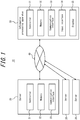
- FIGS. 1 to 3 An overview and configuration of the system 10 for providing a software development environment according to the present embodiment are described with reference to FIGS. 1 to 3 .
- the system 10 for providing a software development environment includes a plurality of servers 20 and an information processing apparatus 30.
- the servers 20 and the information processing apparatus 30 are communicably connected to a network 40, such as a mobile communication network and/or the Internet.
- Each server 20 is, for example, installed in a data center or the like.
- Each server 20 is, for example, a server belonging to a cloud computing system or another computing system.
- the system 10 for providing a software development environment provides a user with an environment, for example on the cloud, for developing software by combining a plurality of development components.
- the user operates the information processing apparatus 30 to access the cloud, which is formed by the plurality of servers 20, using a web browser on the information processing apparatus 30, for example.
- the user can then develop software by combining a plurality of development components on an interface displayed by the web browser.
- the system 10 for providing a software development environment in FIG. 1 includes three servers 20, but this example is not limiting.
- the system 10 for providing a software development environment may include fewer than three servers 20 or may include four or more servers 20.
- the number of servers 20 may also be one.
- the server 20 includes a controller 21, a memory 22, and a communication interface 23.
- the controller 21 includes at least one processor, at least one dedicated circuit, or a combination thereof.
- the processor may, for example, be a general-purpose processor, such as a central processing unit (CPU) or graphics processing unit (GPU), or a dedicated processor specialized for particular processing.
- the dedicated circuit may, for example, be a field-programmable gate array (FPGA) or an application specific integrated circuit (ASIC).
- the controller 21 executes processing related to operation of the server 20 while controlling each component of the server 20.
- the memory 22 includes at least one semiconductor memory, at least one magnetic memory, at least one optical memory, or a combination of at least two of these.
- the semiconductor memory is, for example, random access memory (RAM) or read only memory (ROM).
- the RAM is, for example, static random access memory (SRAM) or dynamic random access memory (DRAM).
- the ROM is, for example, electrically erasable programmable read only memory (EEPROM).
- the memory 22 functions as, for example, a main memory, an auxiliary memory, or a cache memory.
- the memory 22 stores data to be used for operation of the server 20 and data resulting from operation of the server 20.
- the communication interface 23 includes at least one interface for communication with an external destination.
- the interface for communication may be an interface for wired communication or wireless communication.
- the interface for communication may be a local area network (LAN) interface or a universal serial bus (USB), for example.
- the interface for communication may be an interface conforming to a mobile communication standard, such as Long Term Evolution (LTE), 4th Generation (4G), or 5th Generation (5G), or an interface conforming to short-range wireless communication such as Bluetooth ® (Bluetooth is a registered trademark in Japan, other countries, or both).
- LTE Long Term Evolution
- 4G 4th Generation
- 5G 5th Generation
- Bluetooth Bluetooth is a registered trademark in Japan, other countries, or both.
- the communication interface 23 receives data for use in operation of the server 20 and transmits data resulting from operation of the server 20.
- the functions of the server 20 are implemented by a processor corresponding to the controller 21 executing a program according to the present embodiment. In other words, the functions of the server 20 are implemented by software.
- the program causes a computer to function as the server 20 by causing the computer to execute the operations of the server 20. In other words, the computer functions as the server 20 by executing the operations of the server 20 in accordance with the program.
- the program according to the present embodiment can be recorded on a computer readable recording medium.
- Computer readable recording media include non-transitory computer readable recording media, examples of which are a magnetic recording apparatus, an optical disc, a magneto-optical recording medium, and a semiconductor memory.
- the program is, for example, distributed by the sale, transfer, or lending of a portable recording medium such as a digital versatile disk (DVD) or a compact disk read only memory (CD-ROM) on which the program is recorded.
- DVD digital versatile disk
- CD-ROM compact disk read only memory
- the program may also be distributed by storing the program in the storage of an external server and transmitting the program from the external server to another computer.
- the program may also be provided as a program product.
- a portion or all of the functions of the server 20 may be implemented by a dedicated circuit corresponding to the controller 21. In other words, a portion or all of the functions of the server 20 may be implemented by hardware.
- the information processing apparatus 30 includes a controller 31, a memory 32, a communication interface 33, an input interface 34, and a display 35.
- the controller 31 includes at least one processor, at least one dedicated circuit, or a combination thereof.
- the processor may be a general-purpose processor, such as a CPU or GPU, or a dedicated processor specialized for particular processing.
- the dedicated circuit is, for example, an FPGA or an ASIC.
- the controller 31 executes processing related to operation of the information processing apparatus 30 while controlling each component of the information processing apparatus 30.
- the memory 32 includes at least one semiconductor memory, at least one magnetic memory, at least one optical memory, or a combination of at least two of these.
- the semiconductor memory is, for example, RAM or ROM.
- the RAM is, for example, SRAM or DRAM.
- the ROM is, for example, EEPROM.
- the memory 32 functions as, for example, a main memory, an auxiliary memory, or a cache memory.
- the memory 32 stores data to be used for operation of the information processing apparatus 30 and data resulting from operation of the information processing apparatus 30.
- the communication interface 33 includes at least one interface for communication with an external destination.
- the interface for communication may be an interface for wired communication or wireless communication.
- the interface for communication may be a LAN interface or a USB, for example.
- the interface for communication may be an interface conforming to a mobile communication standard, such as LTE, 4G, or 5G, or an interface conforming to short-range wireless communication such as Bluetooth ® .
- the communication interface 33 receives data for use in operation of the information processing apparatus 30 and transmits data resulting from operation of the information processing apparatus 30.
- the input interface 34 includes at least one interface for input.
- the interface for input is, for example, a physical key, a capacitive key, a pointing device, or a touchscreen integrally provided with a display.
- the input interface 34 receives an operation for inputting data used in operation of the information processing apparatus 30.
- the input interface 34 may be connected to the information processing apparatus 30 as an external input device. Any appropriate connection method can be used, such as USB, High-Definition Multimedia Interface (HDMI ® ) (HDMI is a registered trademark in Japan, other countries, or both), or Bluetooth ® .
- HDMI High-Definition Multimedia Interface
- the display 35 includes at least one interface for display output.
- the interface for output is, for example, a display.
- the display may, for example, be a liquid crystal display (LCD) or an organic electro luminescence (EL) display.
- the display 35 outputs data resulting from operation of the information processing apparatus 30 by displaying the data.
- the display 35 may be connected to the information processing apparatus 30 as an external output device. Any appropriate connection method can be used, such as USB, HDMI ® , or Bluetooth ® .
- the functions of the information processing apparatus 30 are implemented by a processor corresponding to the controller 31 executing a program according to the present embodiment. In other words, the functions of the information processing apparatus 30 are implemented by software.
- the program causes a computer to function as the information processing apparatus 30 by causing the computer to execute the operations of the information processing apparatus 30. In other words, the computer functions as the information processing apparatus 30 by executing the operations of the information processing apparatus 30 in accordance with the program.
- the computer in the present embodiment temporarily stores, in the main memory, the program recorded on a portable recording medium or transferred from a server, for example.
- the computer uses a processor to read the program stored in the main memory and executes processing with the processor in accordance with the read program.
- the computer may read the program directly from the portable recording medium and execute processing in accordance with the program.
- Each time the program is received from an external server, the computer may sequentially execute processing in accordance with the received program.
- Processing may be executed by an application service provider (ASP) type of service that implements functions only via execution instructions and result acquisition, without transmission of the program from an external server to the computer.
- Examples of the program include an equivalent to the program represented as information provided for processing by an electronic computer. For example, data that is not a direct command for a computer but that has the property of specifying processing by the computer corresponds to the "equivalent to the program".
- a portion or all of the functions of the information processing apparatus 30 may be implemented by a dedicated circuit corresponding to the controller 31. In other words, a portion or all of the functions of the information processing apparatus 30 may be implemented by hardware.
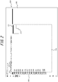
- FIG. 2 illustrates an example of a user interface displayed on the display 35 of the information processing apparatus 30.
- the user operates the input interface 34 of the information processing apparatus 30 to access the server 20 via a web browser, for example.
- the user then develops software by combining a plurality of development components on the user interface displayed in the web browser. It is thus not necessary in the present embodiment to install, on the information processing apparatus 30, an application or the like that is specialized for the system 10 for providing a software development environment.
- the information processing apparatus 30 includes a web browser application, the user can develop software by connecting to the server 20 from the information processing apparatus 30.
- the user interface 200 illustrated in FIG. 2 includes a builder area 210, a development component selection area 220, and a property area 240.
- the builder area 210 is an area for a plurality of development components to be placed, connected, and the like.
- the user develops software by combining a plurality of development components in the builder area 210.
- the builder area 210 includes an overview screen 211.
- the overview screen 211 displays an overview of the placed development components using a reduced-size screen. In other words, the overview screen 211 is a screen displaying all of the placed development components at a reduced size.
- the range displayed by the builder area 210 (display area) is indicated in the overview screen 211 by a display range frame 212.
- the display area of the builder area 210 can be expanded or reduced by magnification adjustment tools 213 to 215.
- the development component selection area 220 is an area for displaying a plurality of development components 221 to 235 that are placeable in the builder area 210.
- the property area 240 is an area for displaying and editing setting information and the like pertaining to a development component selected in the builder area 210.
- the development components in the present embodiment are classified into types such as trigger, action, connector, and logic.
- the development components 221 to 225 illustrated in FIG. 2 are classified as triggers.
- the development components classified as triggers are components pertaining to the occurrence of some sort of event, such as the acquisition of a sensor value from a sensor such as a temperature sensor, humidity sensor, or pressure sensor, the elapse of a predetermined length of time, or the occurrence of a predetermined alarm on a device.
- the development components 226 to 230 are classified as actions.
- the development components classified as actions are components pertaining to an operation, processing, or the like, such as calculation processing, notification, or uploading of data, that is performed when an event occurs.
- the development components 231 to 233 are classified as connectors.
- the development components classified as connectors are components pertaining to information processing with an external resource, such as connection to a database, device, or the like and the addition, updating, deletion, etc. of information thereon.
- the development components 234 to 235 are classified as logic.
- the development components classified as logic are components pertaining to the logical sum, filtering, or the like of input information.
- the user manipulates a mouse pointer or the like to develop software on the user interface 200. For example, the user manipulates a mouse pointer to select a desired development component from the development component selection area 220 and then places, connects, etc. the selected, desired development component in the builder area 210.
- FIG. 3 is a diagram illustrating a trigger selection dialog box in the system for providing a software development environment according to an embodiment of the present disclosure.
- a trigger selection dialog box 250 illustrated in FIG. 3 is displayed when no development component has been placed in the builder area 210.
- the trigger selection dialog box 250 is a dialog screen for the user to select a development component to place first in the builder area 210. In other words, the user is prompted by the trigger selection dialog box 250 to perform the first operation necessary for software development. The user can thereby easily start developing software.
- the trigger selection dialog box 250 includes development components 251 to 255, which respectively correspond to the development components 221 to 225 of the development component selection area 220.
- FIG. 4 is a diagram illustrating a user interface in which the development component selected in the trigger selection dialog box 250 is placed in the builder area 210.
- the development component selected in the trigger selection dialog box 250 is placed in the builder area 210.
- a development component 300 corresponding to a sensor is placed in the builder area 210.
- Properties are associated with the development component 300.
- the properties include a variety of variables, conditional expressions, setting information, and the like pertaining to the development component.
- the user defines various actions and the like for each development component. In other words, the user can develop software by placing and connecting development components and setting the setting information, with no need whatsoever for writing program code.
- FIG. 5 is an example in which a plurality of development components has been placed and connected in the builder area 210.
- development components 301 to 311 have been placed and are connected by links 401 to 410.
- the link 401 indicates that the output of the development component 301 is the input of the development component 305.
- the link 402 indicates that the output of the development component 302 is the input of the development component 305.
- the link 403 indicates that the output of the development component 303 is the input of the development component 305.
- the link 404 indicates that the output of the development component 304 is the input of the development component 306.
- the link 405 indicates that the output of the development component 305 is the input of the development component 307.
- the link 406 indicates that the output of the development component 307 is the input of the development component 306.
- the link 407 indicates that the output of the development component 306 is the input of the development component 308.
- the link 408 indicates that the output of the development component 306 is the input of the development component 309.
- the link 409 indicates that the output of the development component 306 is the input of the development component 310.
- the link 410 indicates that the output of the development component 306 is the input of the development component 311. Properties are associated with each of the development components 301 to 311.
- the development components 301 to 311 are displayed in a display form that includes the corresponding icons 501 to 511, names 601 to 611, and properties 701 to 711.
- the icons 501 to 511 are associated with respective icons displayed in the development component selection area 220.
- the names 601 to 611 are identification information for uniquely identifying each development component.
- the properties 701 to 711 are setting information associated with the respective development components. In this way, the name and properties of each development component are displayed in the user interface 200 illustrated as an example in FIG. 5 , thereby enabling the user to gain a bird's-eye view of the setting information and the like of a plurality of development components.
- the display area of the builder area 210 can be enlarged or reduced by the magnification adjustment tools 213 to 215.
- the system 10 for providing a software development environment presents information corresponding to the display magnification to suppress a reduction in visibility using the operations illustrated below.
- FIG. 6 is a flowchart illustrating operations by the system 10 for providing a software development environment, i.e. an example of a method for providing a software development environment.
- the controller 3 1 of the information processing apparatus 30 displays the user interface 200 on the display 35 at an initially set display magnification (step S10).
- the initially set display magnification is, for example, 100%.
- FIG. 5 is an example of the user interface 200 displayed in this case.
- the user interface 200 includes the builder area 210 and the development component selection area 220, which displays a plurality of development components placeable in the builder area 210.
- a request to display the user interface 200 is based on an input operation from the user.
- the controller 31 uses the input interface 34 to receive an input operation by the user on the web browser.
- the controller 31 communicates with the server 20 via the communication interface 33 and receives data pertaining to the user interface 200.
- the controller 31 displays the user interface 200 on the display 35 based on the data.
- An authentication process or the like pertaining to the user may be performed by the server 20 and the information processing apparatus 30 as appropriate.
- the input interface 34 receives input for a request to change the display magnification (change request) (step S20).
- the change request is received based on an operation on the magnification adjustment tools 213 to 215.
- the input interface 34 receives a click on the magnification adjustment tool 213.
- This operation corresponds to a change request to reduce the display magnification by a predetermined value.
- the predetermined value is, for example, 1%. Accordingly, clicking 10 times on the magnification adjustment tool 213, for example, reduces the display magnification by 10%.
- the input interface 34 receives a click on the magnification adjustment tool 215.
- This operation corresponds to a change request to increase the display magnification by a predetermined value.
- the predetermined value is, for example, 1%.
- the input interface 34 receives input of a number to the magnification adjustment tool 214. This operation corresponds to a change request to change the display magnification to the inputted numerical value.
- the controller 31 displays each development component in accordance with the display magnification on the display 35 (step S30).
- the controller 31 displays each development component on the display 35 in a display form that includes the corresponding icon, regardless of the display magnification.
- the controller 31 displays each development component in a display form that includes less information when the display magnification is below a predetermined magnification than when the display magnification is equal to or greater than the predetermined magnification.
- each development component is displayed in a display form that does not include the properties pertaining to the development component when the display magnification is below a first threshold. Conversely, each development component is displayed in a display form that includes the properties when the display magnification is equal to or greater than the first threshold.
- the first threshold is, for example, 90%.
- Each development component is displayed in a display form that does not include the name pertaining to the development component when the display magnification is below a second threshold. Conversely, each development component is displayed in a display form that includes the name when the display magnification is equal to or greater than the second threshold.
- the second threshold is, for example, 70%.
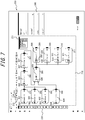
- FIGS. 7 and 8 are diagrams illustrating an overview of these operations.
- FIGS. 7 and 8 are display examples for the cases of the display magnification being 89% and 69% respectively.
- the display magnification is 89%, the display magnification is below the first threshold and is equal to or greater than the second threshold.
- the development components 301 to 311 are therefore displayed in a display form that includes the respective icons 501 to 511 and names 601 to 611 pertaining to the development components.
- the development components 301 to 311 do not include the properties 701 to 711 pertaining to the development components.
- the display magnification is 69%
- the display magnification is below the first threshold and is below the second threshold.
- the development components 301 to 311 are therefore displayed in a display form that includes the icons 501 to 511 pertaining to the development components.
- the development components 301 to 311 do not include the names 601 to 611 and properties 701 to 711 pertaining to the development components.
- each development component is displayed in a display form that includes less information when the display magnification is below a predetermined magnification than when the display magnification is equal to or greater than the predetermined magnification. Therefore, a reduction in visibility of information can be suppressed when information is reduced in size and displayed, for example. Furthermore, since each development component is displayed in a display form that includes the corresponding icon, regardless of the display magnification, the user can easily learn what type of development component each development component is, based on the icon. In other words, the distinguishability of each development component can be improved by the icon of the development component being displayed regardless of the display magnification.
- each development component when the display magnification is below 90%, for example, each development component is displayed in a display form that does not include the properties pertaining to the development component. Conversely, when the display magnification is equal to or greater than 90%, each development component is displayed in a display form that includes the properties. When the display magnification is below 70%, each development component is displayed in a display form that does not include the name pertaining to the development component. Conversely, when the display magnification is equal to or greater than 70%, each development component is displayed in a display form that includes the name.
- the display form of each development component is switched among three patterns corresponding to the level of display magnification.
- the display form of each development component in the example illustrated in the above embodiment is switched among three patterns, namely a display form that includes only the icon, a display form that includes the icon and the name, and a display form that includes the icon, name, and properties.
- this example is not limiting. Only the first threshold or only the second threshold, for example, may be provided as the threshold. In this case, the display form of each development component may be switched between two patterns. In other words, the threshold may be only the first threshold, for example.
- each development component may be switched between two patterns in this case, namely a display form that includes the icon and the name, and a display form that includes the icon, the name, and the properties.
- the threshold may be only the second threshold, for example.
- the display form of each development component may be switched between two patterns in this case, such as a display form that includes only the icon, and a display form that includes the icon, the name, and the properties.
- FIG. 9 is a diagram illustrating a setting dialog box 260 in the system 10 for providing a software development environment according to an embodiment of the present disclosure.
- the setting dialog box includes setting items 261 to 265.
- the setting item 261 is an item for setting whether to display the trigger selection dialog box. When "Yes" is selected on the setting item 261, the trigger selection dialog box is displayed. On the other hand, when "No" is selected on the setting item 261, the trigger selection dialog box is not displayed.
- the setting item 262 is an item for setting whether to display the overview screen.
- the setting item 263 is an item for setting the size of the icons in the development component selection area 220.
- the setting item 264 is an item for setting whether to display category names in the development component selection area 220.
- the setting item 265 is an item for setting the font size of the name and properties of each development component.
- the visibility of the user interface 200 can be increased by appropriate adjustment of the setting items in accordance with the size and resolution of the display the user is using, the user's eyesight, and the like.
- a portion of the information can also be hidden, for example by hiding the category names in the development component selection area 220, in accordance with the user's skill level to enlarge the builder area 210 and improve the operability, convenience, and the like during development.
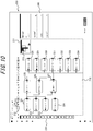
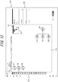
- FIGS. 10 to 12 illustrate examples of operations with the overview screen.
- the display magnification is set to 80%, and the development components 321 to 343 have been placed. While the development components 321 to 334 are displayed in the display example of FIG. 10 , the remaining development components 335 to 343 are outside of the display area and therefore are not displayed in the builder area 210. As described above, all of the placed development components are displayed at a reduced size on the overview screen 211. This can prevent the development components not displayed in the builder area 210 from being overlooked. Furthermore, the display area displayed by the builder area 210 is indicated by the display range frame 212, enabling the user to easily grasp which portion is being displayed in the builder area 210.
- FIG. 11 is an example in which the display magnification of FIG. 10 is reduced to 63% for display.
- the display magnification of FIG. 10 is reduced to 63% for display.
- the display magnification of FIG. 10 is reduced to 63% for display.
- the position of the display range frame 212 can also be changed based on user operation, and the display area of the builder area 210 can be changed by this operation.
- the user can change the position of the display range frame 212 by a click, drag-and-drop, or the like on any location in the overview screen 211.
- FIG. 12 illustrates a display example for the case of the display range frame 212 being changed to the area where the development components 340 to 343 are located.
- Such a change in the display position on the overview screen 211 enables easy and quick switching so that the development components that the user wishes to view or edit are displayed in the builder area 210.
- the overview screen 211 enables quick access to any location while displaying an overview of the software.
- the development components of the same type may be displayed by an object that integrates a plurality of development components (integrated object).
- the third threshold is lower than the second threshold and may, for example, be 60%.
- a plurality of development components of the same type may be displayed by an integrated object instead of by separate objects when the display magnification is below the third threshold.
- the development components of the same type are development components associated with the same icon and connected to the same destination development component. For example, the icons of the development components 301, 302, 303 placed in the builder area 210 of FIG.
- FIG. 8 illustrates an example of the case of displaying these development components by an integrated object.
- the display magnification is 59%, which is below the third threshold.
- the development components 301, 302, 303 in FIG. 8 can be replaced by an integrated object 801, as illustrated in FIG. 13 .
- the integrated object 801 is displayed in a form that includes an icon 901 to facilitate identification of the type of the integrated development components. Displaying the integrated object 801 this way reduces the number of objects in the builder area 210 and can prevent a reduction in visibility when the display magnification is low (below the third threshold).
- the integrated object may be displayed in a display form that includes the number of integrated development components.
- the integrated object 801 in FIG. 13 includes a badge 1001.
- the badge is an object that displays the number of integrated development components.
- three objects are integrated, i.e. the development components 301, 302, 303.
- the badge therefore indicates "3".
- the integrated object 801 is displayed in a display form with the badge 1001 attached thereto. The user can thereby easily learn the number of integrated development components.
- the properties 701 to 711 displayed when the display magnification is equal to or greater than the first threshold may be a portion of all of the settable information for the development components 301 to 311.
- the properties may be only a portion of information selected from among all settable information pertaining to the plurality of development components. Limiting the displayed properties to a portion of information in this way enables the user to easily recognize an overview of the software.
- the information amount of the properties such as the number of items of the properties, the number of display characters, and the number of significant digits, may change in accordance with display magnification.
- the information amount of the properties may be increased to be higher when the display magnification is equal to or greater than a fourth threshold than when the display magnification is below the fourth threshold.
- the fourth threshold is higher than the second threshold and may, for example, be 110%. The information amount of the properties can thus be increased when the display magnification is large and a sufficient area for displaying information is ensured. This enables the user to grasp the content of software more easily.
- the properties to be added when the display magnification reaches the fourth threshold may be specifiable by the user.
- the properties to be added when the display magnification reaches the fourth threshold may also be based on an operation history pertaining to the plurality of development components.
- the information amount of the properties may be increased based on an operation history pertaining to the plurality of development components when the display magnification is equal to or greater than the fourth threshold.
- the operation history pertaining to the plurality of display components includes a history of operations to change the properties pertaining to each development component, for example. Based on the history of past operations to change the properties, a frequently changed property, recently changed property, or the like may, for example, become a property to be added when the display magnification reaches the fourth threshold.
- the properties to be added when the display magnification reaches the fourth threshold may also be determined by machine learning based on an operation history pertaining to the plurality of development components.
- the correlation between the history of revisions to the setting information by the user and the probability of occurrence of bugs may be used in the machine learning.
- Any appropriate algorithm for machine learning may be used, such as a convolutional neural network (CNN), a recurrent neural network (RNN), or deep learning.
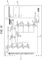
- FIG. 14 is an example of the user interface 200 displayed when the display magnification is below the second threshold.
- a mouse pointer 270 is placed over the development component 311.
- the properties pertaining to the development component 311 subjected to the mouseover are displayed.
- the properties pertaining to the development components 311 are displayed by a tooltip 280.
- a display example for when the display magnification is below the second threshold is illustrated here, but this example is not limiting.
- a similar display may be provided when the display magnification is equal to or greater than the second threshold. That is, when a mouseover operation is performed on any development component among the plurality of development components, the properties pertaining to the development component subjected to the mouseover operation may be displayed regardless of the display magnification. By the properties pertaining to the development component subjected to the mouseover being displayed by the tooltip 280 in this way, the properties of each development component 311 can easily be grasped.
- the information processing apparatus 30 has been described as accessing the server 20 via a web browser in the present embodiment to provide the user with a software development environment, but this example is not limiting.
- an application according to the system 10 for providing a software development environment may be installed on the information processing apparatus 30, and a software development environment may be provided to the user by communication with the server 20 via the application.
Landscapes
- Engineering & Computer Science (AREA)
- Software Systems (AREA)
- General Engineering & Computer Science (AREA)
- Theoretical Computer Science (AREA)
- Physics & Mathematics (AREA)
- General Physics & Mathematics (AREA)
- Human Computer Interaction (AREA)
- User Interface Of Digital Computer (AREA)
- Stored Programmes (AREA)
Abstract
A system for providing a software development environment, a method for providing a software development environment, and a non-transitory computer readable medium that can improve the convenience of a user interface of a software development environment are provided. A display is configured to display a user interface on which the plurality of development components is placed. A controller is configured to change a display form of each development component and display each development component on the display in accordance with a request to change a display magnification. Each development component is displayed in a display form that includes less information when the display magnification is below a predetermined magnification than when the display magnification is equal to or greater than the predetermined magnification, and each development component is displayed in a display form that includes a corresponding icon regardless of the display magnification.
Description
- The present application claims priority to
Japanese Patent Application No. 2020-114205 filed on July 1, 2020 - The present disclosure relates to a system for providing a software development environment, a method for providing a software development environment, and a non-transitory computer readable medium.
- Along with advances in technology pertaining to the Internet of Things (IOT), systems have been proposed for automatic control of various devices, sensors, and the like connected to a network in plants, factories, buildings, residences, and the like. For example, various systems (engineering systems) have been constructed in plants, factories, and the like, such as a distributed control system, a manufacturing execution system (MES), a plant information management system (PIMS), and an enterprise resource planning (ERP) system.
- The development of software implemented in these engineering systems, such as applications, workflow, and programs, has been achieved using an apparatus installed in a plant, such as a programmable logic controller (PLC). Patent literature (PTL) 1, for example, proposes technology to support software development using a visual programming tool. Specifically,
PTL 1 discloses the development of software by representing various processes, such as functions, collectively as an object and representing the relationships between processes by wires connecting the processes. - PTL 1:
JP 2020-42679 A - When numerous objects are combined to develop software using the technology in
PTL 1, however, the overall picture of the software becomes harder to grasp as the number of combined objects increases. In other words, there is room for improvement in the convenience of the user interface of the software development environment. - It would be helpful to provide a system for providing a software development environment, a method for providing a software development environment, and a non-transitory computer readable medium that can improve the convenience of the user interface of a software development environment.
- A system for providing a software development environment according to an embodiment is a system for providing a software development environment to develop software by combining a plurality of development components, the system including an information processing apparatus that includes a display and a controller, wherein
the display is configured to display a user interface on which the plurality of development components is placed,
the controller is configured to change a display form of each development component and display each development component on the display in accordance with a request to change a display magnification, and
each development component is displayed in a display form that includes less information when the display magnification is below a predetermined magnification than when the display magnification is equal to or greater than the predetermined magnification, and each development component is displayed in a display form that includes a corresponding icon regardless of the display magnification. - According to the system for providing a software development environment in an embodiment, an overview of software formed by a combination of a plurality of development components can become easier to grasp as a result of switching the display magnification. Each development component is displayed in a display form that includes less information when the display magnification is below a predetermined magnification than when the display magnification is equal to or greater than the predetermined magnification. Therefore, a reduction in visibility of information can be suppressed when information is reduced in size and displayed, for example. Furthermore, since each development component is displayed in a display form that includes the corresponding icon, regardless of the display magnification, the distinguishability of each development component can be improved by the icon. In other words, the user can easily learn what type of development component each development component is regardless of the display magnification. The convenience of the user interface of a software development environment can thus be improved by the system for providing a software development environment in an embodiment.
- In an embodiment, each development component may be displayed in a display form that does not include a property pertaining to the development component when the display magnification is below a first threshold, and each development component may be displayed in a display form that includes the property when the display magnification is equal to or greater than the first threshold.
- According to the system for providing a software development environment in an embodiment, each development component is thus displayed in a display form that does not include a property pertaining to the development component when the display magnification is below the first threshold. Therefore, a reduction in visibility of information can be suppressed when information is reduced in size and displayed, for example. Also, each development component is displayed in a display form that includes the property when the display magnification is equal to or greater than the first threshold. The distinguishability of each development component can therefore be further improved.
- In an embodiment, each development component may be displayed in a display form that does not include a name of the development component when the display magnification is below a second threshold, each development component may be displayed in a display form that includes the name when the display magnification is equal to or greater than the second threshold, and the second threshold may be lower than the first threshold.
- According to the system for providing a software development environment in an embodiment, each development component is thus displayed in a display form that does not include a name pertaining to the development component when the display magnification is below the second threshold. Therefore, a reduction in visibility of information can be suppressed when information is reduced in size and displayed, for example. Also, each development component is displayed in a display form that includes the name when the display magnification is equal to or greater than the second threshold. Information pertaining to each development component can therefore be learned more easily.
- In an embodiment, the plurality of development components may include at least two development components that are associated with the same icon and are connected to the same destination development component, and
the at least two development components may be integrated by a corresponding integrated object and displayed when the display magnification is below a third threshold. - According to the system for providing a software development environment in an embodiment, the integrated object can be displayed to reduce the number of objects and prevent a reduction in visibility when the display magnification is low.
- In an embodiment, the integrated object may be displayed in a display form that includes the number of integrated development components.
- According to the system for providing a software development environment in an embodiment, the user can thus easily learn the number of integrated development components.
- In an embodiment, an information amount of the property may be increased to be higher when the display magnification is equal to or greater than a fourth threshold than when the display magnification is below the fourth threshold, and the fourth threshold may be higher than the first threshold.
- According to the system for providing a software development environment in an embodiment, the information amount of the property can thus be increased when the display magnification is greater than the fourth threshold and a sufficient area for displaying information is ensured. This enables the user to grasp the content of software more easily.
- In an embodiment, the information amount of the property may be increased based on an operation history pertaining to the plurality of development components when the display magnification is equal to or greater than the fourth threshold.
- According to the system for providing a software development environment in an embodiment, the viewability of properties with a high priority can thus be increased, improving convenience for the user. This configuration can also prevent program bugs and facilitate debugging.
- In an embodiment, when a mouseover operation is performed on any development component among the plurality of development components, a property pertaining to the development component subjected to the mouseover operation may be displayed regardless of the display magnification.
- According to the system for providing a software development environment in an embodiment, a property pertaining to the development component subjected to the mouseover operation is thus displayed regardless of the display magnification. The property of each development component can therefore be learned easily.
- A method for providing a software development environment according to an embodiment is a method for providing a software development environment to develop software by combining a plurality of development components, the method including:
- displaying a user interface on which the plurality of development components is placed; and
- changing a display form of each development component and displaying each development component in accordance with a request to change a display magnification;
- wherein each development component is displayed in a display form that includes less information when the display magnification is below a predetermined magnification than when the display magnification is equal to or greater than the predetermined magnification, and each development component is displayed in a display form that includes a corresponding icon regardless of the display magnification.
- According to the method for providing a software development environment in an embodiment, an overview of software formed by a combination of a plurality of development components can become easier to grasp as a result of switching the display magnification. Each development component is displayed in a display form that includes less information when the display magnification is below a predetermined magnification than when the display magnification is equal to or greater than the predetermined magnification. Therefore, a reduction in visibility of information can be suppressed when information is reduced in size and displayed, for example. Furthermore, since each development component is displayed in a display form that includes the corresponding icon, regardless of the display magnification, the distinguishability of each development component can be improved by the icon. In other words, the user can easily learn what type of development component each development component is regardless of the display magnification. The convenience of the user interface of a software development environment can thus be improved by the method for providing a software development environment in an embodiment.
- A non-transitory computer readable medium according to an embodiment is a non-transitory computer readable medium storing a program, for providing a software development environment, configured to cause a processor to execute operations including:
- displaying a user interface on which a plurality of development components is placed; and
- changing a display form of each development component and displaying each development component in accordance with a request to change a display magnification;
- wherein each development component is displayed in a display form that includes less information when the display magnification is below a predetermined magnification than when the display magnification is equal to or greater than the predetermined magnification, and each development component is displayed in a display form that includes a corresponding icon regardless of the display magnification.
- According to the non-transitory computer readable medium storing a program for providing a software development environment in an embodiment, an overview of software formed by a combination of a plurality of development components can become easier to grasp as a result of switching the display magnification. Each development component is displayed in a display form that includes less information when the display magnification is below a predetermined magnification than when the display magnification is equal to or greater than the predetermined magnification. Therefore, a reduction in visibility of information can be suppressed when information is reduced in size and displayed, for example. Furthermore, since each development component is displayed in a display form that includes the corresponding icon, regardless of the display magnification, the distinguishability of each development component can be improved by the icon. In other words, the user can easily learn what type of development component each development component is regardless of the display magnification. In this way, the convenience of the user interface of a software development environment can be improved by the non-transitory computer readable medium that stores a program for providing a software development environment in an embodiment.
- According to the present disclosure, a system for providing a software development environment, a method for providing a software development environment, and a non-transitory computer readable medium that can improve technology related to the user interface of a software development environment can be provided.
- In the accompanying drawings:
-
FIG. 1 is a functional block diagram of a system for providing a software development environment according to an embodiment of the present disclosure; -
FIG. 2 is a diagram illustrating a user interface in the system for providing a software development environment according to an embodiment of the present disclosure; -
FIG. 3 is a diagram illustrating a trigger selection dialog box in the system for providing a software development environment according to an embodiment of the present disclosure; -
FIG. 4 is a diagram illustrating a user interface in which the development component selected in the trigger selection dialog box is placed; -
FIG. 5 is a diagram illustrating a user interface on which a plurality of development components is placed; -
FIG. 6 is a flowchart illustrating a method for providing a software development environment according to an embodiment of the present disclosure; -
FIG. 7 is a diagram illustrating an overview of operations in the method for providing a software development environment according to an embodiment of the present disclosure; -
FIG. 8 is a diagram illustrating an overview of operations in the method for providing a software development environment according to an embodiment of the present disclosure; -
FIG. 9 is a diagram illustrating a setting dialog box in the system for providing a software development environment according to an embodiment of the present disclosure; -
FIG. 10 is a diagram illustrating operation of an overview screen in the system for providing a software development environment according to an embodiment of the present disclosure; -
FIG. 11 is a diagram illustrating operation of an overview screen in the system for providing a software development environment according to an embodiment of the present disclosure; -
FIG. 12 is a diagram illustrating operation of an overview screen in the system for providing a software development environment according to an embodiment of the present disclosure; -
FIG. 13 is a diagram illustrating an example in which an integrated object is displayed in the system for providing a software development environment according to an embodiment of the present disclosure; and -
FIG. 14 is a diagram illustrating an example display during a mouseover in the system for providing a software development environment according to an embodiment of the present disclosure. - A
system 10 for providing a software development environment according to an embodiment of the present disclosure is described below with reference to the drawings. - Identical or equivalent portions in the drawings are labeled with the same reference signs. In the explanation of the present embodiment, a description of identical or equivalent portions is omitted or simplified as appropriate.
- An overview and configuration of the
system 10 for providing a software development environment according to the present embodiment are described with reference toFIGS. 1 to 3 . - The
system 10 for providing a software development environment according to the present embodiment includes a plurality ofservers 20 and aninformation processing apparatus 30. Theservers 20 and theinformation processing apparatus 30 are communicably connected to anetwork 40, such as a mobile communication network and/or the Internet. Eachserver 20 is, for example, installed in a data center or the like. Eachserver 20 is, for example, a server belonging to a cloud computing system or another computing system. In overview, thesystem 10 for providing a software development environment provides a user with an environment, for example on the cloud, for developing software by combining a plurality of development components. The user operates theinformation processing apparatus 30 to access the cloud, which is formed by the plurality ofservers 20, using a web browser on theinformation processing apparatus 30, for example. The user can then develop software by combining a plurality of development components on an interface displayed by the web browser. Thesystem 10 for providing a software development environment inFIG. 1 includes threeservers 20, but this example is not limiting. Thesystem 10 for providing a software development environment may include fewer than threeservers 20 or may include four ormore servers 20. The number ofservers 20 may also be one. - The configurations of the
server 20 and theinformation processing apparatus 30 according to the present embodiment are described below. - As illustrated in
FIG. 1 , theserver 20 includes acontroller 21, amemory 22, and acommunication interface 23. - The
controller 21 includes at least one processor, at least one dedicated circuit, or a combination thereof. The processor may, for example, be a general-purpose processor, such as a central processing unit (CPU) or graphics processing unit (GPU), or a dedicated processor specialized for particular processing. The dedicated circuit may, for example, be a field-programmable gate array (FPGA) or an application specific integrated circuit (ASIC). Thecontroller 21 executes processing related to operation of theserver 20 while controlling each component of theserver 20. - The
memory 22 includes at least one semiconductor memory, at least one magnetic memory, at least one optical memory, or a combination of at least two of these. The semiconductor memory is, for example, random access memory (RAM) or read only memory (ROM). The RAM is, for example, static random access memory (SRAM) or dynamic random access memory (DRAM). The ROM is, for example, electrically erasable programmable read only memory (EEPROM). Thememory 22 functions as, for example, a main memory, an auxiliary memory, or a cache memory. Thememory 22 stores data to be used for operation of theserver 20 and data resulting from operation of theserver 20. - The
communication interface 23 includes at least one interface for communication with an external destination. The interface for communication may be an interface for wired communication or wireless communication. In the case of wired communication, the interface for communication may be a local area network (LAN) interface or a universal serial bus (USB), for example. In the case of wireless communication, the interface for communication may be an interface conforming to a mobile communication standard, such as Long Term Evolution (LTE), 4th Generation (4G), or 5th Generation (5G), or an interface conforming to short-range wireless communication such as Bluetooth® (Bluetooth is a registered trademark in Japan, other countries, or both). Thecommunication interface 23 receives data for use in operation of theserver 20 and transmits data resulting from operation of theserver 20. - The functions of the
server 20 are implemented by a processor corresponding to thecontroller 21 executing a program according to the present embodiment. In other words, the functions of theserver 20 are implemented by software. The program causes a computer to function as theserver 20 by causing the computer to execute the operations of theserver 20. In other words, the computer functions as theserver 20 by executing the operations of theserver 20 in accordance with the program. - The program according to the present embodiment can be recorded on a computer readable recording medium. Computer readable recording media include non-transitory computer readable recording media, examples of which are a magnetic recording apparatus, an optical disc, a magneto-optical recording medium, and a semiconductor memory. The program is, for example, distributed by the sale, transfer, or lending of a portable recording medium such as a digital versatile disk (DVD) or a compact disk read only memory (CD-ROM) on which the program is recorded. The program may also be distributed by storing the program in the storage of an external server and transmitting the program from the external server to another computer. The program may also be provided as a program product.
- A portion or all of the functions of the
server 20 may be implemented by a dedicated circuit corresponding to thecontroller 21. In other words, a portion or all of the functions of theserver 20 may be implemented by hardware. - The
information processing apparatus 30 includes acontroller 31, amemory 32, acommunication interface 33, aninput interface 34, and adisplay 35. - The
controller 31 includes at least one processor, at least one dedicated circuit, or a combination thereof. The processor may be a general-purpose processor, such as a CPU or GPU, or a dedicated processor specialized for particular processing. The dedicated circuit is, for example, an FPGA or an ASIC. Thecontroller 31 executes processing related to operation of theinformation processing apparatus 30 while controlling each component of theinformation processing apparatus 30. - The
memory 32 includes at least one semiconductor memory, at least one magnetic memory, at least one optical memory, or a combination of at least two of these. The semiconductor memory is, for example, RAM or ROM. The RAM is, for example, SRAM or DRAM. The ROM is, for example, EEPROM. Thememory 32 functions as, for example, a main memory, an auxiliary memory, or a cache memory. Thememory 32 stores data to be used for operation of theinformation processing apparatus 30 and data resulting from operation of theinformation processing apparatus 30. - The
communication interface 33 includes at least one interface for communication with an external destination. The interface for communication may be an interface for wired communication or wireless communication. In the case of wired communication, the interface for communication may be a LAN interface or a USB, for example. In the case of wireless communication, the interface for communication may be an interface conforming to a mobile communication standard, such as LTE, 4G, or 5G, or an interface conforming to short-range wireless communication such as Bluetooth®. Thecommunication interface 33 receives data for use in operation of theinformation processing apparatus 30 and transmits data resulting from operation of theinformation processing apparatus 30. - The
input interface 34 includes at least one interface for input. The interface for input is, for example, a physical key, a capacitive key, a pointing device, or a touchscreen integrally provided with a display. Theinput interface 34 receives an operation for inputting data used in operation of theinformation processing apparatus 30. Instead of being provided in theinformation processing apparatus 30, theinput interface 34 may be connected to theinformation processing apparatus 30 as an external input device. Any appropriate connection method can be used, such as USB, High-Definition Multimedia Interface (HDMI®) (HDMI is a registered trademark in Japan, other countries, or both), or Bluetooth®. - The
display 35 includes at least one interface for display output. The interface for output is, for example, a display. The display may, for example, be a liquid crystal display (LCD) or an organic electro luminescence (EL) display. Thedisplay 35 outputs data resulting from operation of theinformation processing apparatus 30 by displaying the data. Instead of being provided in theinformation processing apparatus 30, thedisplay 35 may be connected to theinformation processing apparatus 30 as an external output device. Any appropriate connection method can be used, such as USB, HDMI®, or Bluetooth®. - The functions of the
information processing apparatus 30 are implemented by a processor corresponding to thecontroller 31 executing a program according to the present embodiment. In other words, the functions of theinformation processing apparatus 30 are implemented by software. The program causes a computer to function as theinformation processing apparatus 30 by causing the computer to execute the operations of theinformation processing apparatus 30. In other words, the computer functions as theinformation processing apparatus 30 by executing the operations of theinformation processing apparatus 30 in accordance with the program. - The computer in the present embodiment temporarily stores, in the main memory, the program recorded on a portable recording medium or transferred from a server, for example. The computer uses a processor to read the program stored in the main memory and executes processing with the processor in accordance with the read program. The computer may read the program directly from the portable recording medium and execute processing in accordance with the program. Each time the program is received from an external server, the computer may sequentially execute processing in accordance with the received program. Processing may be executed by an application service provider (ASP) type of service that implements functions only via execution instructions and result acquisition, without transmission of the program from an external server to the computer. Examples of the program include an equivalent to the program represented as information provided for processing by an electronic computer. For example, data that is not a direct command for a computer but that has the property of specifying processing by the computer corresponds to the "equivalent to the program".
- A portion or all of the functions of the
information processing apparatus 30 may be implemented by a dedicated circuit corresponding to thecontroller 31. In other words, a portion or all of the functions of theinformation processing apparatus 30 may be implemented by hardware. -
FIG. 2 illustrates an example of a user interface displayed on thedisplay 35 of theinformation processing apparatus 30. The user operates theinput interface 34 of theinformation processing apparatus 30 to access theserver 20 via a web browser, for example. The user then develops software by combining a plurality of development components on the user interface displayed in the web browser. It is thus not necessary in the present embodiment to install, on theinformation processing apparatus 30, an application or the like that is specialized for thesystem 10 for providing a software development environment. In other words, as long as theinformation processing apparatus 30 includes a web browser application, the user can develop software by connecting to theserver 20 from theinformation processing apparatus 30. - The
user interface 200 illustrated inFIG. 2 includes abuilder area 210, a developmentcomponent selection area 220, and aproperty area 240. Thebuilder area 210 is an area for a plurality of development components to be placed, connected, and the like. The user develops software by combining a plurality of development components in thebuilder area 210. Thebuilder area 210 includes anoverview screen 211. Theoverview screen 211 displays an overview of the placed development components using a reduced-size screen. In other words, theoverview screen 211 is a screen displaying all of the placed development components at a reduced size. The range displayed by the builder area 210 (display area) is indicated in theoverview screen 211 by adisplay range frame 212. The display area of thebuilder area 210 can be expanded or reduced bymagnification adjustment tools 213 to 215. The developmentcomponent selection area 220 is an area for displaying a plurality of development components 221 to 235 that are placeable in thebuilder area 210. Theproperty area 240 is an area for displaying and editing setting information and the like pertaining to a development component selected in thebuilder area 210. - The development components in the present embodiment are classified into types such as trigger, action, connector, and logic. The development components 221 to 225 illustrated in
FIG. 2 are classified as triggers. The development components classified as triggers are components pertaining to the occurrence of some sort of event, such as the acquisition of a sensor value from a sensor such as a temperature sensor, humidity sensor, or pressure sensor, the elapse of a predetermined length of time, or the occurrence of a predetermined alarm on a device. Thedevelopment components 226 to 230 are classified as actions. The development components classified as actions are components pertaining to an operation, processing, or the like, such as calculation processing, notification, or uploading of data, that is performed when an event occurs. The development components 231 to 233 are classified as connectors. The development components classified as connectors are components pertaining to information processing with an external resource, such as connection to a database, device, or the like and the addition, updating, deletion, etc. of information thereon. The development components 234 to 235 are classified as logic. The development components classified as logic are components pertaining to the logical sum, filtering, or the like of input information. The user manipulates a mouse pointer or the like to develop software on theuser interface 200. For example, the user manipulates a mouse pointer to select a desired development component from the developmentcomponent selection area 220 and then places, connects, etc. the selected, desired development component in thebuilder area 210. -
FIG. 3 is a diagram illustrating a trigger selection dialog box in the system for providing a software development environment according to an embodiment of the present disclosure. A triggerselection dialog box 250 illustrated inFIG. 3 is displayed when no development component has been placed in thebuilder area 210. The triggerselection dialog box 250 is a dialog screen for the user to select a development component to place first in thebuilder area 210. In other words, the user is prompted by the triggerselection dialog box 250 to perform the first operation necessary for software development. The user can thereby easily start developing software. The triggerselection dialog box 250 includes development components 251 to 255, which respectively correspond to the development components 221 to 225 of the developmentcomponent selection area 220. -
FIG. 4 is a diagram illustrating a user interface in which the development component selected in the triggerselection dialog box 250 is placed in thebuilder area 210. For example, suppose that the user has operated a mouse pointer and selected the development component 251 pertaining to a sensor in the triggerselection dialog box 250. In this case, as illustrated inFIG. 4 , adevelopment component 300 corresponding to a sensor is placed in thebuilder area 210. Properties are associated with thedevelopment component 300. The properties include a variety of variables, conditional expressions, setting information, and the like pertaining to the development component. By selecting and setting properties such as various settings, variables, conditional expressions, and so forth from pulldown menus or the like in theproperty area 240, the user defines various actions and the like for each development component. In other words, the user can develop software by placing and connecting development components and setting the setting information, with no need whatsoever for writing program code. -
FIG. 5 is an example in which a plurality of development components has been placed and connected in thebuilder area 210. InFIG. 5 ,development components 301 to 311 have been placed and are connected bylinks 401 to 410. Thelink 401 indicates that the output of thedevelopment component 301 is the input of thedevelopment component 305. Thelink 402 indicates that the output of thedevelopment component 302 is the input of thedevelopment component 305. Thelink 403 indicates that the output of thedevelopment component 303 is the input of thedevelopment component 305. Thelink 404 indicates that the output of thedevelopment component 304 is the input of thedevelopment component 306. The link 405 indicates that the output of thedevelopment component 305 is the input of thedevelopment component 307. Thelink 406 indicates that the output of thedevelopment component 307 is the input of thedevelopment component 306. Thelink 407 indicates that the output of thedevelopment component 306 is the input of thedevelopment component 308. Thelink 408 indicates that the output of thedevelopment component 306 is the input of thedevelopment component 309. Thelink 409 indicates that the output of thedevelopment component 306 is the input of thedevelopment component 310. Thelink 410 indicates that the output of thedevelopment component 306 is the input of thedevelopment component 311. Properties are associated with each of thedevelopment components 301 to 311. - As illustrated in
FIG. 5 , thedevelopment components 301 to 311 are displayed in a display form that includes the correspondingicons 501 to 511,names 601 to 611, andproperties 701 to 711. Theicons 501 to 511 are associated with respective icons displayed in the developmentcomponent selection area 220. Thenames 601 to 611 are identification information for uniquely identifying each development component. Theproperties 701 to 711 are setting information associated with the respective development components. In this way, the name and properties of each development component are displayed in theuser interface 200 illustrated as an example inFIG. 5 , thereby enabling the user to gain a bird's-eye view of the setting information and the like of a plurality of development components. Here, the display area of thebuilder area 210 can be enlarged or reduced by themagnification adjustment tools 213 to 215. When each development component is reduced in size and displayed, however, information pertaining to the name and properties also ends up reduced in size and could suffer reduced visibility. To address this issue, thesystem 10 for providing a software development environment according to an embodiment of the present disclosure presents information corresponding to the display magnification to suppress a reduction in visibility using the operations illustrated below. -
FIG. 6 is a flowchart illustrating operations by thesystem 10 for providing a software development environment, i.e. an example of a method for providing a software development environment. - First, the
controller 3 1 of theinformation processing apparatus 30 displays theuser interface 200 on thedisplay 35 at an initially set display magnification (step S10). The initially set display magnification is, for example, 100%.FIG. 5 is an example of theuser interface 200 displayed in this case. As described above, theuser interface 200 includes thebuilder area 210 and the developmentcomponent selection area 220, which displays a plurality of development components placeable in thebuilder area 210. Here, a request to display theuser interface 200 is based on an input operation from the user. For example, thecontroller 31 uses theinput interface 34 to receive an input operation by the user on the web browser. Upon receiving the input operation, thecontroller 31 communicates with theserver 20 via thecommunication interface 33 and receives data pertaining to theuser interface 200. Thecontroller 31 then displays theuser interface 200 on thedisplay 35 based on the data. An authentication process or the like pertaining to the user may be performed by theserver 20 and theinformation processing apparatus 30 as appropriate. - Next, the
input interface 34 receives input for a request to change the display magnification (change request) (step S20). The change request is received based on an operation on themagnification adjustment tools 213 to 215. For example, theinput interface 34 receives a click on themagnification adjustment tool 213. This operation corresponds to a change request to reduce the display magnification by a predetermined value. The predetermined value is, for example, 1%. Accordingly, clicking 10 times on themagnification adjustment tool 213, for example, reduces the display magnification by 10%. For example, theinput interface 34 receives a click on themagnification adjustment tool 215. This operation corresponds to a change request to increase the display magnification by a predetermined value. The predetermined value is, for example, 1%. Accordingly, clicking 10 times on themagnification adjustment tool 215, for example, increases the display magnification by 10%. For example, theinput interface 34 receives input of a number to themagnification adjustment tool 214. This operation corresponds to a change request to change the display magnification to the inputted numerical value. - When the change request is received, the
controller 31 displays each development component in accordance with the display magnification on the display 35 (step S30). Here, thecontroller 31 displays each development component on thedisplay 35 in a display form that includes the corresponding icon, regardless of the display magnification. On the other hand, thecontroller 31 displays each development component in a display form that includes less information when the display magnification is below a predetermined magnification than when the display magnification is equal to or greater than the predetermined magnification. - Specifically, each development component is displayed in a display form that does not include the properties pertaining to the development component when the display magnification is below a first threshold. Conversely, each development component is displayed in a display form that includes the properties when the display magnification is equal to or greater than the first threshold. The first threshold is, for example, 90%. Each development component is displayed in a display form that does not include the name pertaining to the development component when the display magnification is below a second threshold. Conversely, each development component is displayed in a display form that includes the name when the display magnification is equal to or greater than the second threshold. The second threshold is, for example, 70%.
-
FIGS. 7 and8 are diagrams illustrating an overview of these operations.FIGS. 7 and8 are display examples for the cases of the display magnification being 89% and 69% respectively. When the display magnification is 89%, the display magnification is below the first threshold and is equal to or greater than the second threshold. As illustrated inFIG. 7 , thedevelopment components 301 to 311 are therefore displayed in a display form that includes therespective icons 501 to 511 andnames 601 to 611 pertaining to the development components. On the other hand, thedevelopment components 301 to 311 do not include theproperties 701 to 711 pertaining to the development components. - When the display magnification is 69%, the display magnification is below the first threshold and is below the second threshold. As illustrated in
FIG. 8 , thedevelopment components 301 to 311 are therefore displayed in a display form that includes theicons 501 to 511 pertaining to the development components. On the other hand, thedevelopment components 301 to 311 do not include thenames 601 to 611 andproperties 701 to 711 pertaining to the development components. - According to the
system 10 for providing a software development environment in the present embodiment, an overview of software formed by a combination of a plurality of development components can become easier to grasp as a result of switching the display magnification. Each development component is displayed in a display form that includes less information when the display magnification is below a predetermined magnification than when the display magnification is equal to or greater than the predetermined magnification. Therefore, a reduction in visibility of information can be suppressed when information is reduced in size and displayed, for example. Furthermore, since each development component is displayed in a display form that includes the corresponding icon, regardless of the display magnification, the user can easily learn what type of development component each development component is, based on the icon. In other words, the distinguishability of each development component can be improved by the icon of the development component being displayed regardless of the display magnification. - In greater detail, when the display magnification is below 90%, for example, each development component is displayed in a display form that does not include the properties pertaining to the development component. Conversely, when the display magnification is equal to or greater than 90%, each development component is displayed in a display form that includes the properties. When the display magnification is below 70%, each development component is displayed in a display form that does not include the name pertaining to the development component. Conversely, when the display magnification is equal to or greater than 70%, each development component is displayed in a display form that includes the name. By a plurality of thresholds being set in this way, the information amount of each displayed development component can be ensured in conjunction with each display magnification, and a reduction in visibility due to the display magnification can be prevented.
- Although the present disclosure is based on embodiments and drawings, it is to be noted that various changes and modifications will be apparent to those skilled in the art based on the present disclosure. Therefore, such changes and modifications are to be understood as included within the scope of the present disclosure. For example, the functions and the like included in the components, steps, and the like may be reordered in any logically consistent way. Furthermore, components, steps, and the like may be combined into one or divided.
- For example, two thresholds are provided in the above embodiment, the first threshold and the second threshold, and the display form of each development component is switched among three patterns corresponding to the level of display magnification. Specifically, the display form of each development component in the example illustrated in the above embodiment is switched among three patterns, namely a display form that includes only the icon, a display form that includes the icon and the name, and a display form that includes the icon, name, and properties. However, this example is not limiting. Only the first threshold or only the second threshold, for example, may be provided as the threshold. In this case, the display form of each development component may be switched between two patterns. In other words, the threshold may be only the first threshold, for example. The display form of each development component may be switched between two patterns in this case, namely a display form that includes the icon and the name, and a display form that includes the icon, the name, and the properties. The threshold may be only the second threshold, for example. The display form of each development component may be switched between two patterns in this case, such as a display form that includes only the icon, and a display form that includes the icon, the name, and the properties.
- Various settings pertaining to the
user interface 200, such as the font size in theuser interface 200, may be changeable by the user, for example. These settings may, for example, be set by a setting dialog box.FIG. 9 is a diagram illustrating a settingdialog box 260 in thesystem 10 for providing a software development environment according to an embodiment of the present disclosure. The setting dialog box includes settingitems 261 to 265. The settingitem 261 is an item for setting whether to display the trigger selection dialog box. When "Yes" is selected on thesetting item 261, the trigger selection dialog box is displayed. On the other hand, when "No" is selected on thesetting item 261, the trigger selection dialog box is not displayed. The settingitem 262 is an item for setting whether to display the overview screen. When "Display" is selected on thesetting item 262, the overview screen is displayed in the builder area. Conversely, when "Not display" is selected on thesetting item 262, the overview screen is not displayed. The settingitem 263 is an item for setting the size of the icons in the developmentcomponent selection area 220. Here, three different sizes can be set. The settingitem 264 is an item for setting whether to display category names in the developmentcomponent selection area 220. When "Display" is selected on thesetting item 264, the category names are displayed in the developmentcomponent selection area 220. Conversely, when "Not display" is selected on thesetting item 264, the category names are not displayed in the developmentcomponent selection area 220. The settingitem 265 is an item for setting the font size of the name and properties of each development component. Here, three different sizes can be set. The visibility of theuser interface 200 can be increased by appropriate adjustment of the setting items in accordance with the size and resolution of the display the user is using, the user's eyesight, and the like. A portion of the information can also be hidden, for example by hiding the category names in the developmentcomponent selection area 220, in accordance with the user's skill level to enlarge thebuilder area 210 and improve the operability, convenience, and the like during development. - When the number of development components is large, setting the overview screen to be displayed by the setting
item 262 can improve operability of theuser interface 200.FIGS. 10 to 12 illustrate examples of operations with the overview screen. In the example inFIG. 10 , the display magnification is set to 80%, and thedevelopment components 321 to 343 have been placed. While thedevelopment components 321 to 334 are displayed in the display example ofFIG. 10 , the remainingdevelopment components 335 to 343 are outside of the display area and therefore are not displayed in thebuilder area 210. As described above, all of the placed development components are displayed at a reduced size on theoverview screen 211. This can prevent the development components not displayed in thebuilder area 210 from being overlooked. Furthermore, the display area displayed by thebuilder area 210 is indicated by thedisplay range frame 212, enabling the user to easily grasp which portion is being displayed in thebuilder area 210. -
FIG. 11 is an example in which the display magnification ofFIG. 10 is reduced to 63% for display. As illustrated inFIG. 11 , when the number of placed development components is large, it may not be possible to display all of the development components in thebuilder area 210 even when the display magnification is below the second threshold. As described above, all of the placed development components are displayed at a reduced size on theoverview screen 211 in this case as well. This can prevent the development components not displayed in thebuilder area 210 from being overlooked. Furthermore, the display area displayed by thebuilder area 210 is indicated by thedisplay range frame 212, enabling the user to easily grasp which portion is being displayed in thebuilder area 210. - The position of the
display range frame 212 can also be changed based on user operation, and the display area of thebuilder area 210 can be changed by this operation. The user can change the position of thedisplay range frame 212 by a click, drag-and-drop, or the like on any location in theoverview screen 211.FIG. 12 illustrates a display example for the case of thedisplay range frame 212 being changed to the area where thedevelopment components 340 to 343 are located. Such a change in the display position on theoverview screen 211 enables easy and quick switching so that the development components that the user wishes to view or edit are displayed in thebuilder area 210. In other words, theoverview screen 211 enables quick access to any location while displaying an overview of the software. - When a plurality of development components placed in the
builder area 210 includes a plurality of development components of the same type, and the display magnification is below a third threshold, the development components of the same type may be displayed by an object that integrates a plurality of development components (integrated object). The third threshold is lower than the second threshold and may, for example, be 60%. In other words, a plurality of development components of the same type may be displayed by an integrated object instead of by separate objects when the display magnification is below the third threshold. The development components of the same type are development components associated with the same icon and connected to the same destination development component. For example, the icons of thedevelopment components builder area 210 ofFIG. 8 , described above, are all the same icon (an icon pertaining to a sensor). Thedevelopment components development component 305. That is, thedevelopment components FIG. 13 illustrates an example of the case of displaying these development components by an integrated object. InFIG. 13 , the display magnification is 59%, which is below the third threshold. In this case, thedevelopment components FIG. 8 can be replaced by anintegrated object 801, as illustrated inFIG. 13 . Theintegrated object 801 is displayed in a form that includes anicon 901 to facilitate identification of the type of the integrated development components. Displaying theintegrated object 801 this way reduces the number of objects in thebuilder area 210 and can prevent a reduction in visibility when the display magnification is low (below the third threshold). - The integrated object may be displayed in a display form that includes the number of integrated development components. The
integrated object 801 inFIG. 13 includes abadge 1001. The badge is an object that displays the number of integrated development components. InFIG. 13 , three objects are integrated, i.e. thedevelopment components integrated object 801 is displayed in a display form with thebadge 1001 attached thereto. The user can thereby easily learn the number of integrated development components. - In the above embodiment, the
properties 701 to 711 displayed when the display magnification is equal to or greater than the first threshold may be a portion of all of the settable information for thedevelopment components 301 to 311. In other words, the properties may be only a portion of information selected from among all settable information pertaining to the plurality of development components. Limiting the displayed properties to a portion of information in this way enables the user to easily recognize an overview of the software. Furthermore, the information amount of the properties, such as the number of items of the properties, the number of display characters, and the number of significant digits, may change in accordance with display magnification. Specifically, the information amount of the properties may be increased to be higher when the display magnification is equal to or greater than a fourth threshold than when the display magnification is below the fourth threshold. The fourth threshold is higher than the second threshold and may, for example, be 110%. The information amount of the properties can thus be increased when the display magnification is large and a sufficient area for displaying information is ensured. This enables the user to grasp the content of software more easily. - The properties to be added when the display magnification reaches the fourth threshold may be specifiable by the user. The properties to be added when the display magnification reaches the fourth threshold may also be based on an operation history pertaining to the plurality of development components. In other words, the information amount of the properties may be increased based on an operation history pertaining to the plurality of development components when the display magnification is equal to or greater than the fourth threshold. The operation history pertaining to the plurality of display components includes a history of operations to change the properties pertaining to each development component, for example. Based on the history of past operations to change the properties, a frequently changed property, recently changed property, or the like may, for example, become a property to be added when the display magnification reaches the fourth threshold. The properties to be added when the display magnification reaches the fourth threshold may also be determined by machine learning based on an operation history pertaining to the plurality of development components. The correlation between the history of revisions to the setting information by the user and the probability of occurrence of bugs may be used in the machine learning. Any appropriate algorithm for machine learning may be used, such as a convolutional neural network (CNN), a recurrent neural network (RNN), or deep learning. By the property to be added when the display magnification reaches the fourth threshold being determined in this way based on an operation history pertaining to the plurality of development components, the viewability of properties with a high priority can be increased, improving convenience for the user. This configuration can also prevent program bugs and facilitate debugging.
- When an operation to place the mouse over any development component among the plurality of development components (mouseover operation) is performed, a property pertaining to the development component subjected to the mouseover operation may be displayed regardless of the display magnification.
FIG. 14 is an example of theuser interface 200 displayed when the display magnification is below the second threshold. Here, amouse pointer 270 is placed over thedevelopment component 311. In this case, the properties pertaining to thedevelopment component 311 subjected to the mouseover are displayed. InFIG. 14 , the properties pertaining to thedevelopment components 311 are displayed by atooltip 280. A display example for when the display magnification is below the second threshold is illustrated here, but this example is not limiting. A similar display may be provided when the display magnification is equal to or greater than the second threshold. That is, when a mouseover operation is performed on any development component among the plurality of development components, the properties pertaining to the development component subjected to the mouseover operation may be displayed regardless of the display magnification. By the properties pertaining to the development component subjected to the mouseover being displayed by thetooltip 280 in this way, the properties of eachdevelopment component 311 can easily be grasped. - The
information processing apparatus 30 has been described as accessing theserver 20 via a web browser in the present embodiment to provide the user with a software development environment, but this example is not limiting. For example, an application according to thesystem 10 for providing a software development environment may be installed on theinformation processing apparatus 30, and a software development environment may be provided to the user by communication with theserver 20 via the application.
Claims (10)
- A system for providing a software development environment to develop software by combining a plurality of development components, the system comprising an information processing apparatus that includes a display and a controller, wherein
the display is configured to display a user interface on which the plurality of development components is placed,
the controller is configured to change a display form of each development component and display each development component on the display in accordance with a request to change a display magnification, and
each development component is displayed in a display form that includes less information when the display magnification is below a predetermined magnification than when the display magnification is equal to or greater than the predetermined magnification, and each development component is displayed in a display form that includes a corresponding icon regardless of the display magnification. - The system for providing a software development environment of claim 1, wherein each development component is displayed in a display form that does not include a property pertaining to the development component when the display magnification is below a first threshold, and each development component is displayed in a display form that includes the property when the display magnification is equal to or greater than the first threshold.
- The system for providing a software development environment of claim 2, wherein each development component is displayed in a display form that does not include a name of the development component when the display magnification is below a second threshold, each development component is displayed in a display form that includes the name when the display magnification is equal to or greater than the second threshold, and the second threshold is lower than the first threshold.
- The system for providing a software development environment of claim 3, wherein
the plurality of development components includes at least two development components that are associated with the same icon and are connected to the same destination development component, and
the at least two development components are integrated by a corresponding integrated object and displayed when the display magnification is below a third threshold. - The system for providing a software development environment of claim 4, wherein the integrated object is displayed in a display form that includes the number of integrated development components.
- The system for providing a software development environment of any one of claims 2 to 5, wherein an information amount of the property is increased to be higher when the display magnification is equal to or greater than a fourth threshold than when the display magnification is below the fourth threshold, and the fourth threshold is higher than the first threshold.
- The system for providing a software development environment of claim 6, wherein the information amount of the property is increased based on an operation history pertaining to the plurality of development components when the display magnification is equal to or greater than the fourth threshold.
- The system for providing a software development environment of any one of claims 2 to 7, wherein when a mouseover operation is performed on any development component among the plurality of development components, a property pertaining to the development component subjected to the mouseover operation is displayed regardless of the display magnification.
- A method for providing a software development environment to develop software by combining a plurality of development components, the method comprising:displaying a user interface on which the plurality of development components is placed; andchanging a display form of each development component and displaying each development component in accordance with a request to change a display magnification;wherein each development component is displayed in a display form that includes less information when the display magnification is below a predetermined magnification than when the display magnification is equal to or greater than the predetermined magnification, and each development component is displayed in a display form that includes a corresponding icon regardless of the display magnification.
- A non-transitory computer readable medium storing a program, for providing a software development environment, configured to cause a processor to execute operations comprising:displaying a user interface on which a plurality of development components is placed; andchanging a display form of each development component and displaying each development component in accordance with a request to change a display magnification;wherein each development component is displayed in a display form that includes less information when the display magnification is below a predetermined magnification than when the display magnification is equal to or greater than the predetermined magnification, and each development component is displayed in a display form that includes a corresponding icon regardless of the display magnification.
Applications Claiming Priority (1)
| Application Number | Priority Date | Filing Date | Title |
|---|---|---|---|
| JP2020114205A JP2022012393A (en) | 2020-07-01 | 2020-07-01 | Software development environment providing system, software development environment providing method, and software development environment providing program |
Publications (1)
| Publication Number | Publication Date |
|---|---|
| EP3933571A1 true EP3933571A1 (en) | 2022-01-05 |
Family
ID=76707980
Family Applications (1)
| Application Number | Title | Priority Date | Filing Date |
|---|---|---|---|
| EP21182238.2A Withdrawn EP3933571A1 (en) | 2020-07-01 | 2021-06-29 | System for providing software development environment, method for providing software development environment, and non-transitory computer readable medium |
Country Status (4)
| Country | Link |
|---|---|
| US (1) | US20220004370A1 (en) |
| EP (1) | EP3933571A1 (en) |
| JP (1) | JP2022012393A (en) |
| CN (1) | CN113885851A (en) |
Families Citing this family (1)
| Publication number | Priority date | Publication date | Assignee | Title |
|---|---|---|---|---|
| CN116382728B (en) * | 2023-02-24 | 2023-11-21 | 荣耀终端有限公司 | Propagation name display method and terminal equipment |
Citations (7)
| Publication number | Priority date | Publication date | Assignee | Title |
|---|---|---|---|---|
| US20110225524A1 (en) * | 2010-03-10 | 2011-09-15 | Cifra Christopher G | Multi-Touch Editing in a Graphical Programming Language |
| US20110246635A1 (en) * | 2010-04-06 | 2011-10-06 | Oracle International Corporation | Simplifying determination of dependencies among soa services |
| US20130191767A1 (en) * | 2012-01-25 | 2013-07-25 | Sap Ag | Semantic Zooming of Data Object Representations in a User Interface |
| US20140354650A1 (en) * | 2013-05-30 | 2014-12-04 | Oracle International Corporation | Attribute-based stacking for diagrams |
| US20150106758A1 (en) * | 2013-10-14 | 2015-04-16 | Invensys Systems, Inc. | Semantic zooming in process simulation |
| US20160155249A1 (en) * | 2013-11-22 | 2016-06-02 | Raytheon Company | Interactive multimedia process flow chart builder |
| JP2020042679A (en) * | 2018-09-12 | 2020-03-19 | 株式会社日立製作所 | Device and method for supporting creation of flow using visual programming tool |
Family Cites Families (4)
| Publication number | Priority date | Publication date | Assignee | Title |
|---|---|---|---|---|
| JP2000089944A (en) * | 1998-07-15 | 2000-03-31 | Hitachi Software Eng Co Ltd | Method for displaying connection guide marker, system therefor and recording medium |
| JP4713098B2 (en) * | 2004-07-27 | 2011-06-29 | 株式会社ジャストシステム | Selection item display device, selection item display method, and selection item display program |
| JP2009087280A (en) * | 2007-10-03 | 2009-04-23 | Ict Solutions:Kk | Map information display system, terminal device, application server, and map information display program |
| JP5805612B2 (en) * | 2012-11-16 | 2015-11-04 | 株式会社デジタル | Programmable display, control program and control system |
-
2020
- 2020-07-01 JP JP2020114205A patent/JP2022012393A/en not_active Withdrawn
-
2021
- 2021-06-22 CN CN202110692594.7A patent/CN113885851A/en not_active Withdrawn
- 2021-06-28 US US17/360,461 patent/US20220004370A1/en not_active Abandoned
- 2021-06-29 EP EP21182238.2A patent/EP3933571A1/en not_active Withdrawn
Patent Citations (7)
| Publication number | Priority date | Publication date | Assignee | Title |
|---|---|---|---|---|
| US20110225524A1 (en) * | 2010-03-10 | 2011-09-15 | Cifra Christopher G | Multi-Touch Editing in a Graphical Programming Language |
| US20110246635A1 (en) * | 2010-04-06 | 2011-10-06 | Oracle International Corporation | Simplifying determination of dependencies among soa services |
| US20130191767A1 (en) * | 2012-01-25 | 2013-07-25 | Sap Ag | Semantic Zooming of Data Object Representations in a User Interface |
| US20140354650A1 (en) * | 2013-05-30 | 2014-12-04 | Oracle International Corporation | Attribute-based stacking for diagrams |
| US20150106758A1 (en) * | 2013-10-14 | 2015-04-16 | Invensys Systems, Inc. | Semantic zooming in process simulation |
| US20160155249A1 (en) * | 2013-11-22 | 2016-06-02 | Raytheon Company | Interactive multimedia process flow chart builder |
| JP2020042679A (en) * | 2018-09-12 | 2020-03-19 | 株式会社日立製作所 | Device and method for supporting creation of flow using visual programming tool |
Also Published As
| Publication number | Publication date |
|---|---|
| JP2022012393A (en) | 2022-01-17 |
| US20220004370A1 (en) | 2022-01-06 |
| CN113885851A (en) | 2022-01-04 |
Similar Documents
| Publication | Publication Date | Title |
|---|---|---|
| US11301813B2 (en) | Digital processing systems and methods for hierarchical table structure with conditional linking rules in collaborative work systems | |
| US11816309B2 (en) | User interface logical and execution view navigation and shifting | |
| KR101794373B1 (en) | Temporary formatting and charting of selected data | |
| US10031654B2 (en) | Apparatus and method for generating industrial process graphics | |
| US20100107108A1 (en) | Method and system for generating a control system user interface | |
| CN112579050A (en) | Task-based configuration rendering context | |
| US10976725B2 (en) | User interface widget modeling and placement | |
| CN115840422B (en) | System, method, and computer-readable medium for developing industrial applications | |
| US20220108507A1 (en) | Map Data Visualizations with Multiple Superimposed Marks Layers | |
| CN114116441A (en) | UI (user interface) testing method and device, electronic equipment and storage medium | |
| US9651926B2 (en) | System, method, work station and computer program product for controlling an industrial process | |
| CN107615191A (en) | Debugging device, debugging method and debugging program | |
| EP3905030A1 (en) | System for providing software development environment, method for providing software development environment, and non-transitory computer readable medium | |
| US20220004370A1 (en) | System for providing software development environment, method for providing software development environment, and non-transitory computer readable medium | |
| US10523523B2 (en) | Infographic search | |
| EP3933562A1 (en) | System for providing software development environment, method for providing software development environment, and non-transitory computer readable medium | |
| EP3905028A1 (en) | System for providing software development environment, method for providing software development environment, and non-transitory computer readable medium | |
| EP3227767B1 (en) | Hierarchical navigation apparatus and method | |
| US20210334074A1 (en) | System for providing software development environment, method for providing software development environment, and non-transitory computer readable medium | |
| US10289756B2 (en) | System and method for designing pin joint | |
| JP2019185685A (en) | Computer program, information processing method and computer | |
| WO2021176982A1 (en) | Display method, control program, and device | |
| US20260119000A1 (en) | Content delivery of contextual information via user interface elements | |
| CN117689122A (en) | Method, system and medium for assisting part change flow management | |
| JP2021179703A (en) | Display method, control program and device |
Legal Events
| Date | Code | Title | Description |
|---|---|---|---|
| PUAI | Public reference made under article 153(3) epc to a published international application that has entered the european phase |
Free format text: ORIGINAL CODE: 0009012 |
|
| STAA | Information on the status of an ep patent application or granted ep patent |
Free format text: STATUS: THE APPLICATION HAS BEEN PUBLISHED |
|
| AK | Designated contracting states |
Kind code of ref document: A1 Designated state(s): AL AT BE BG CH CY CZ DE DK EE ES FI FR GB GR HR HU IE IS IT LI LT LU LV MC MK MT NL NO PL PT RO RS SE SI SK SM TR |
|
| B565 | Issuance of search results under rule 164(2) epc |
Effective date: 20211103 |
|
| STAA | Information on the status of an ep patent application or granted ep patent |
Free format text: STATUS: THE APPLICATION IS DEEMED TO BE WITHDRAWN |
|
| 18D | Application deemed to be withdrawn |
Effective date: 20220706 |