EP3933552B1 - Procédé et dispositif pour déterminer la position du regard d'un utilisateur, support d'enregistrement et appareil électronique - Google Patents
Procédé et dispositif pour déterminer la position du regard d'un utilisateur, support d'enregistrement et appareil électronique Download PDFInfo
- Publication number
- EP3933552B1 EP3933552B1 EP21166294.5A EP21166294A EP3933552B1 EP 3933552 B1 EP3933552 B1 EP 3933552B1 EP 21166294 A EP21166294 A EP 21166294A EP 3933552 B1 EP3933552 B1 EP 3933552B1
- Authority
- EP
- European Patent Office
- Prior art keywords
- user
- image
- target
- display screen
- subspaces
- Prior art date
- Legal status (The legal status is an assumption and is not a legal conclusion. Google has not performed a legal analysis and makes no representation as to the accuracy of the status listed.)
- Active
Links
Images

Classifications
-
- G—PHYSICS
- G06—COMPUTING OR CALCULATING; COUNTING
- G06F—ELECTRIC DIGITAL DATA PROCESSING
- G06F3/00—Input arrangements for transferring data to be processed into a form capable of being handled by the computer; Output arrangements for transferring data from processing unit to output unit, e.g. interface arrangements
- G06F3/01—Input arrangements or combined input and output arrangements for interaction between user and computer
- G06F3/011—Arrangements for interaction with the human body, e.g. for user immersion in virtual reality
- G06F3/013—Eye tracking input arrangements
-
- G—PHYSICS
- G06—COMPUTING OR CALCULATING; COUNTING
- G06V—IMAGE OR VIDEO RECOGNITION OR UNDERSTANDING
- G06V40/00—Recognition of biometric, human-related or animal-related patterns in image or video data
- G06V40/10—Human or animal bodies, e.g. vehicle occupants or pedestrians; Body parts, e.g. hands
- G06V40/18—Eye characteristics, e.g. of the iris
- G06V40/19—Sensors therefor
-
- G—PHYSICS
- G06—COMPUTING OR CALCULATING; COUNTING
- G06F—ELECTRIC DIGITAL DATA PROCESSING
- G06F18/00—Pattern recognition
- G06F18/20—Analysing
- G06F18/21—Design or setup of recognition systems or techniques; Extraction of features in feature space; Blind source separation
- G06F18/214—Generating training patterns; Bootstrap methods, e.g. bagging or boosting
-
- G—PHYSICS
- G06—COMPUTING OR CALCULATING; COUNTING
- G06F—ELECTRIC DIGITAL DATA PROCESSING
- G06F3/00—Input arrangements for transferring data to be processed into a form capable of being handled by the computer; Output arrangements for transferring data from processing unit to output unit, e.g. interface arrangements
- G06F3/01—Input arrangements or combined input and output arrangements for interaction between user and computer
- G06F3/03—Arrangements for converting the position or the displacement of a member into a coded form
- G06F3/0304—Detection arrangements using opto-electronic means
-
- G—PHYSICS
- G06—COMPUTING OR CALCULATING; COUNTING
- G06F—ELECTRIC DIGITAL DATA PROCESSING
- G06F3/00—Input arrangements for transferring data to be processed into a form capable of being handled by the computer; Output arrangements for transferring data from processing unit to output unit, e.g. interface arrangements
- G06F3/01—Input arrangements or combined input and output arrangements for interaction between user and computer
- G06F3/048—Interaction techniques based on graphical user interfaces [GUI]
- G06F3/0487—Interaction techniques based on graphical user interfaces [GUI] using specific features provided by the input device, e.g. functions controlled by the rotation of a mouse with dual sensing arrangements, or of the nature of the input device, e.g. tap gestures based on pressure sensed by a digitiser
- G06F3/0488—Interaction techniques based on graphical user interfaces [GUI] using specific features provided by the input device, e.g. functions controlled by the rotation of a mouse with dual sensing arrangements, or of the nature of the input device, e.g. tap gestures based on pressure sensed by a digitiser using a touch-screen or digitiser, e.g. input of commands through traced gestures
- G06F3/04886—Interaction techniques based on graphical user interfaces [GUI] using specific features provided by the input device, e.g. functions controlled by the rotation of a mouse with dual sensing arrangements, or of the nature of the input device, e.g. tap gestures based on pressure sensed by a digitiser using a touch-screen or digitiser, e.g. input of commands through traced gestures by partitioning the display area of the touch-screen or the surface of the digitising tablet into independently controllable areas, e.g. virtual keyboards or menus
-
- G—PHYSICS
- G06—COMPUTING OR CALCULATING; COUNTING
- G06N—COMPUTING ARRANGEMENTS BASED ON SPECIFIC COMPUTATIONAL MODELS
- G06N3/00—Computing arrangements based on biological models
- G06N3/02—Neural networks
- G06N3/04—Architecture, e.g. interconnection topology
- G06N3/045—Combinations of networks
-
- G—PHYSICS
- G06—COMPUTING OR CALCULATING; COUNTING
- G06N—COMPUTING ARRANGEMENTS BASED ON SPECIFIC COMPUTATIONAL MODELS
- G06N3/00—Computing arrangements based on biological models
- G06N3/02—Neural networks
- G06N3/04—Architecture, e.g. interconnection topology
- G06N3/0464—Convolutional networks [CNN, ConvNet]
-
- G—PHYSICS
- G06—COMPUTING OR CALCULATING; COUNTING
- G06N—COMPUTING ARRANGEMENTS BASED ON SPECIFIC COMPUTATIONAL MODELS
- G06N3/00—Computing arrangements based on biological models
- G06N3/02—Neural networks
- G06N3/08—Learning methods
-
- G—PHYSICS
- G06—COMPUTING OR CALCULATING; COUNTING
- G06N—COMPUTING ARRANGEMENTS BASED ON SPECIFIC COMPUTATIONAL MODELS
- G06N3/00—Computing arrangements based on biological models
- G06N3/02—Neural networks
- G06N3/08—Learning methods
- G06N3/09—Supervised learning
-
- G—PHYSICS
- G06—COMPUTING OR CALCULATING; COUNTING
- G06V—IMAGE OR VIDEO RECOGNITION OR UNDERSTANDING
- G06V10/00—Arrangements for image or video recognition or understanding
- G06V10/20—Image preprocessing
- G06V10/26—Segmentation of patterns in the image field; Cutting or merging of image elements to establish the pattern region, e.g. clustering-based techniques; Detection of occlusion
- G06V10/267—Segmentation of patterns in the image field; Cutting or merging of image elements to establish the pattern region, e.g. clustering-based techniques; Detection of occlusion by performing operations on regions, e.g. growing, shrinking or watersheds
-
- G—PHYSICS
- G06—COMPUTING OR CALCULATING; COUNTING
- G06V—IMAGE OR VIDEO RECOGNITION OR UNDERSTANDING
- G06V20/00—Scenes; Scene-specific elements
- G06V20/10—Terrestrial scenes
-
- G—PHYSICS
- G06—COMPUTING OR CALCULATING; COUNTING
- G06V—IMAGE OR VIDEO RECOGNITION OR UNDERSTANDING
- G06V40/00—Recognition of biometric, human-related or animal-related patterns in image or video data
- G06V40/10—Human or animal bodies, e.g. vehicle occupants or pedestrians; Body parts, e.g. hands
- G06V40/16—Human faces, e.g. facial parts, sketches or expressions
- G06V40/161—Detection; Localisation; Normalisation
Definitions
- the present invention relates to the field of human-computer interaction, including to a method and device for determining a gaze position of a user, and a storage medium.
- WO 2015/0187294 A1 relates to technologies for viewer attention area estimation including a computing device to capture, by a camera system of the computing device, an image of a viewer of a display of the computing device.
- the computing device further determines a distance range of the viewer from the computing device, a gaze direction of the viewer based on the captured image and the distance range of the viewer, and an active interaction region of the display based on the viewer's gaze direction and the distance range of the viewer.
- the active interaction region is indicative of a region of the display at which the viewer's gaze is directed.
- the computing device displays content on the display based on the determined active interaction region.
- CN 111 046 744 A relates to the technical field of image processing, and particularly relates to a region of interest detection method and device, a computer readable storage medium and terminal equipment.
- the method comprises the steps of obtaining a to-be-detected target face image; calculating the head posture of the target face image; extracting a left eye image and a right eye image in the target face image; determining a sight attention direction according to the left eye image, the right eye image and the head posture; carrying out eye key point detection in the left eye image and the right eye image to obtain coordinates of a left eye pupil center point and coordinates of a right eye pupil center point; and determining an eye attention area according to the sight attention direction, the coordinate of the left eye pupil center point and the coordinate of the right eye pupil center point.
- an expensive precision instrument is not needed, and the eye region of interest is determined by analyzing and processing the face image, so that the cost is greatly reduced, and the method can be widely applied.
- the present invention provides a method and device for determining a gaze position of a user, and a storage medium having the features of the independent claims.
- the gaze position of the target user can be identified according to the collected user image and the user distance, so that the cost of the device is reduced while accuracy of identifying the gaze position of the target user is ensured.
- the identifying process of the gaze position of the user has good stability and a wide application scope, so that the user has good use experience.
- the application scenarios include a terminal with a display screen, and the terminal is provided with an infrared sensor and a camera device.
- the terminal with the display screen can also use an external infrared sensor and camera device, and the external infrared sensor and camera device need to transmit obtained data to the terminal with the display screen via Bluetooth or Wi-Fi and so on, which is not described in detail here.
- the infrared sensor and camera device may be a universal infrared sensor and camera on a smart hardware terminal.
- the terminal can be a mobile terminal equipped with the infrared sensor and camera device, such as a smart phone, a tablet computer, a smart watch, a smart bracelet, PDA (Personal Digital Assistant) and so on, or it can be a fixed terminal, such as a desktop computer and a smart TV
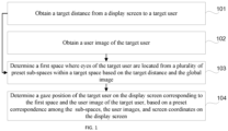
- FIG. 1 is a flowchart of a method for determining a gaze position of a user according to some embodiments, which is applied to the terminal described in the above application scenario. As shown in FIG. 1 , the method can include steps described below.
- step 101 a target distance from the display screen to a target user is obtained.
- a user image of the target user is obtained.
- the user image includes a global image, a head image, and an eye image.
- the global image is a plane image of a target space in front of the display screen.
- the above method for determining a gaze position of a user is described through an example in which a smart TV is used as the terminal.
- the smart TV can first obtain monitoring information in the target space in front of the smart TV by the camera device and/or infrared sensor, and select the target user from multiple users according to the monitoring information.
- the monitoring information may be a length of stay of the user, a distance of the user from the TV, or a standing time of the user.
- the target user may be a user who stays the longest in front of the smart TV, a user who is closest to the smart TV, or a user who remains stationary for the longest time. After the target user is determined, an operation right of the smart TV is granted to the target user.
- the above expression of "an operation right of the smart TV is granted to the target user" actually means to enable a process of collecting the target distance and user image corresponding to the target user.
- the user image includes a global image, a head image, and an eye image, which are in three dimensions.
- the global image is a plane image of the target space in front of the smart TV It can be understood that the plane image includes a portrait part and a background part of the target space.
- the eye image may be a high resolution image including the eyes of the target user.
- the head image may include the entire head of the target user.
- the head image is applied to coordinate prediction models described later, which can provide assistance to the analysis of a sight angle of the target user.
- the head image can be an image including the head that is obtained by performing image recognition on the global image and then performing interception. Therefore, the above-mentioned head image, global image and the eye image can be collected by a universal front camera in the smart TV or the mobile terminal.
- a pixel requirement of the head image and the global image can be set to 12 million pixels, and an aspect ratio of the head image can be 1:1, and an aspect ratio of the global image can be 16 :9.
- the eye image is a core parameter for determining the gaze position of the user, the eye image can be obtained by a high-precision camera included in the camera device.
- a pixel requirement for the eye image is at least 48 million pixels, and an aspect ratio of the eye image can be 16:9.
- the data used to determine the gaze position of the user can be collected by the universal camera device on the terminal, which solved the problem of increased hardware costs caused by collecting data through customized devices such as infrared emitting devices or wearable devices.
- a first space where eyes of the target user are located is determined from a plurality of preset subspaces within the target space based on the target distance and the global image. For example, the following method may be used to pre-set the plurality of subspaces: dividing the target space into a plurality of subspaces according to a shooting angle range and an effective shooting distance of an image capturing device.
- a horizontal shooting angle range of the image capturing device can be divided in the horizontal direction at a first preset angle interval to obtain a plurality of first subspaces in the horizontal direction
- a vertical shooting angle range of the image capturing device is divided in the vertical direction at a second preset angle interval to obtain a plurality of second subspaces in the vertical direction
- the effective shooting distance of the image capturing device is divided into third subspaces in a from-far-to-near direction at a preset distance interval, and subspaces obtained by intersecting and separating the first subspaces, the second subspaces and the third subspaces are determined as the subspaces of the target space.
- the space is divided, based on the shooting angle range and effective shooting distance of the camera device, into subspaces by, for example, a test machine of the same model as the terminal, or a server used for development, during the development stage.
- the horizontal shooting angle range can be divided into nine horizontal measurement spaces h_position (i.e., the above-mentioned first subspace) of 0°, 15°, 30°, 45°, 60°, 75°, 90°, 105° and 120° in a clockwise direction at an interval of 15°.
- the vertical shooting angle range can be divided into five vertical measurement spaces v_position (i.e., the above-mentioned second subspace) of 60°, 45°, 30°, 15° and 0° from top to bottom at an interval of 15°.
- v_position i.e., the above-mentioned second subspace
- the effective shooting distance of 10 meters is divided into five distance positions (distance) (i.e., the above-mentioned third subspace) from far-to-near at an interval of 2 meters.
- distance distance positions
- a gaze position of the target user on the display screen corresponding to the first space and the user image of the target user is determined based on a preset correspondence among the subspaces, the user images, and screen coordinates on the display screen.
- a preset number of coordinate points for example, 100 coordinate points
- 100 coordinate points can be extracted from the countless coordinate points contained in the display screen according to a size of the display screen of the smart TV
- These 100 coordinate points are the above-mentioned screen coordinates, and the screen coordinates can be interpreted as coordinate points.
- screen coordinates can be evenly distributed on the display screen in a grid; the screen coordinates can also be interpreted as a sub-area, that is, the display screen can also be divided directly into a preset number of sub-areas, for example, 100 sub-areas, and an area coordinates of each sub-area are used as the screen coordinates herein.
- the screen coordinates corresponding to the first space and the user image of the target user can be determined based on the correspondence, and then the gaze position of the target user on the display screen can be determined according to the screen coordinates.
- step 104 corresponding operations can be performed on the gaze position of the target user on the display screen, for example, a control cursor on the display screen is moved to the gaze position, or a virtual button at the gaze position is selected, so that operation instructions issued by the user through eye movements, voice, or a remote control device of the smart TV can be performed.
- the target distance from the display screen to the target user can be obtained; and the user image of the target user can be obtained, and the user image includes the global image, the head image, and the eye image, and the global image is an image of the target space in front of the display screen, the first space where the eyes of the target user are located is determined from the plurality of preset subspaces within the target space based on the target distance and the global image and the gaze position of the target user on the display screen corresponding to the first space and the user image of the target user are determined based on the preset correspondence among the subspaces, the user images, and the screen coordinates on the display screen.
- the gaze position of the target user can be identified according to the collected user image and the user distance, so that the device cost is reduced while accuracy of identifying the gaze position of the target user is ensured. In this way, the identifying process of the gaze position of the user has good stability and a wide application scope, so that the user has good use experience.
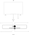
- FIG. 2A is a schematic structural diagram showing a terminal according to some embodiments.
- the terminal is a smart TV 200 which includes a control device 210 and a display screen 220.
- the control device 210 is disposed at the center of the underpart of the smart TV (often referred to as a chin position).
- FIG. 2B is a schematic structural diagram showing a control device of the terminal according to some embodiments.
- the control device 210 includes an infrared sensor 211, a camera device 212, an indicator light 213, and a power button 214.
- the infrared sensor 211 and the camera device 212 can be controlled to be enabled at the same time.
- the target distance from the display screen 220 to the target user can be obtained by the infrared sensor 211, and the user image of the target user is obtained by the camera device 212 at the same time.
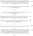
- FIG. 2C is a flowchart showing a method for determining a gaze position as shown in FIG. 1 . As shown in FIG. 2C , such step 104 may include steps 1041 to 1042.
- step 1041 screen coordinates on the display screen corresponding to the first space and the user image of the target user are determined based on the preset correspondence among the screen coordinates on the display screen and the subspaces, the user image.
- the display screen is divided into a plurality of sub-areas in advance according to a size of the display screen, and coordinates of a preset position in each of the sub-areas are used as screen coordinates of that sub-area.
- step 1041 may include: determining a pre-trained coordinate prediction model for the first space; and inputting the user image of the target user into the coordinate prediction model to obtain the screen coordinates on the display screen corresponding to the user image of the target user. For each of the subspaces, a coordinate prediction model is trained based on the user image and screen coordinates of the gaze position of the user on the display screen.
- the number of coordinate prediction models is consistent with the number of spatial positions. For example, in a case where a spatial position where the eyes of a test user are located are determined, an image sample (and its corresponding screen coordinates) of the test user at this time is determined. A combination of a plurality of groups of image samples of the user obtained based on the same spatial location and their corresponding screen coordinates is used as a training data set. A preset neural network model is trained through n different training data sets, and then n above-mentioned coordinate prediction models can be obtained. Based on the training process, the smart TV purchased and used by the user already contains n coordinate prediction models trained in advance, and each of the coordinate prediction models corresponds to one subspace.
- the following steps can be used to train the coordinate prediction model.
- an initial coordinate prediction model is constructed for each of the subspaces.
- each screen coordinate can be regarded as a class, and a process of determining a coordinate label corresponding to the user image can be implemented as a multi-class process, where each screen coordinate corresponds to a coordinate label, and each coordinate label corresponds to a class in the multi-class process.
- a neural network model can be used as the aforementioned initial coordinate prediction model to realize the multi-class process.
- the neural network model includes: a convolutional layer, a pooling layer, and a fully connected layer.
- the convolutional layer is configured to extract image features from the user image, and then obtain a feature vector matrix of each image.
- convolution kernels can be used to extract partial features.
- a larger convolution kernel for example, a convolution kernel containing a pixel matrix of 100* 100, can be used for feature extraction.
- step b a labeled training data set is obtained for that subspace.
- the labeled training data set is inputted into the initial coordinate prediction model.
- the training data set includes a plurality of groups of training data, and each group of training data includes: a user image sample of a test user and a screen coordinate label corresponding to the user image sample, and the training data is labeled with the screen coordinate labels.
- each group of training data includes: a user image sample of a test user and a screen coordinate label corresponding to the user image sample, and the training data is labeled with the screen coordinate labels.
- each training data also has a user portrait of the test user.
- the user portrait may include: user identification (ID), age, gender, race and the like.
- the training data is selected so that the training data set corresponding to the same subspace contains user image samples of test users with different user IDs, different ages, different genders, and different races.
- the method for determining the gaze position of the user further includes the following steps: obtaining a user portrait of the target user according to registration information of the user; classifying the user portrait of the target user to obtain a class of the user portrait.
- the incorporation of the user portrait can increase the pertinence and accuracy of screen coordinate prediction, and further increase the accuracy of determining the gaze position of the user.
- the display screen of the smart TV may be divided into 100 screen coordinates in advance, and these screen coordinates may be labeled on the display screen.
- the test user is positioned in each of the above-mentioned subspaces to gaze at the 100 screen coordinates, and the global images, head images and eye images when the test user gazes at each screen coordinate are recorded to generate the image samples of the user, while the screen coordinates specified by the test user are recorded.
- the above expression "the test user is positioned in each of the aforementioned n subspaces" means that the eyes of the test user are in this subspace.
- Each of screen coordinates corresponds to a unique coordinate label, and the correspondence between the user image sample and the coordinate label can be recorded in the form of (image id, label).
- the screen coordinates can be used for characterizing an accurate position corresponding to a coordinate point, or can be used for characterizing an area within a preset range around the coordinate point.
- step d an obtained prediction result is compared with a labeled value, and parameters of the initial coordinate prediction model are adjusted according to the comparison result until the model converges to obtain the coordinate prediction model which has been trained.
- the number of convolution kernels in the convolution layer can be determined according to the actual training situation, and the convolution kernel parameters can be updated.
- the pooling layer is used for reducing the dimensions of the feature vector matrix to avoid overfitting the training data.
- a maximum value in a sampling area in each of the above three types of images can be used as a sampling feature value.
- Max_pooling maximum pooling operation
- a 2*3 sampling matrix is used to reduce the dimension of the feature vector matrix of the user image by a multiple of 2. For example, as a result of the process of reducing the dimension, the N*N feature vector matrix is reduced to (N-m)*(N-m).
- the fully connected layer further includes a convolutional layer. After a feature vector matrix with highly concentrated features is obtained by means of the convolution operation of the convolutional layer and the dimension reduction operation of the pooling layer, further convolution operations are performed on the highly concentrated feature vector matrix by a softmax function corresponding to the convolution layer contained in the fully connected layer, to obtain the final classification result.
- the determined screen coordinates are determined as the gaze position of the target user on the display screen.
- the output of the coordinate prediction model is actually a prediction probability corresponding to each screen coordinate among the multiple screen coordinates.
- the prediction probability is used for characterizing a probability that the eyes of the target user in the target image are at each of the aforementioned screen coordinates.
- the classification result output by the target coordinate prediction model is obtained, and the classification result is actually a prediction probability that the user image corresponds to each of the screen coordinates. For example, 100 screen coordinates correspond to 100 prediction probabilities.
- the screen coordinates with the highest prediction probability among these 100 screen coordinates are determined, which are the target coordinates corresponding to the user image.
- the target coordinates are on the display screen of the smart TV and can clearly indicate the position of the display screen where the target user is currently gazing.
- another image recognition can be performed on the user image (or other types of user images obtained at the same time as the user image, for example, consecutive multiple eye images of the target user) to determine the different eye actions performed by the target user.
- the eye action may include: blinking, closing eyes, and gazing.
- an operation instruction can be determined according to a binding relationship among the gaze position, the eye action and the operation instruction, and then an operation corresponding to the operation instruction can be executed by the smart TV
- the method may further include step I to II.
- step I a target coordinate label and the user image corresponding to the target coordinates are collected as real-time operation data corresponding to the first sub-subspace.
- step II when a preset amount of real-time operation data is collected, the target coordinate prediction model is trained based on the preset amount of real-time operation data to update the target coordinate prediction model.
- the parameters involved in the process of identifying the gaze position by the above steps 101 to 104 can be collected, namely, the target coordinate label, the user image and the first space.
- the target coordinate label and the user image may be saved as the real-time operation data corresponding to the first sub-subspace.
- the trained coordinate prediction model corresponding to the subspace is updated by the preset amount of real-time operation data to improve the applicability of the coordinate prediction model for the target user.
- a calibration game for collecting the real-time operation data may be provided in the smart TV system.
- the steps of data collection by the calibration game include determining the gaze position of the target user on the display screen through a process similar to the above steps 101 to 103, outputting the gaze position so that the target user can determine whether the gaze position is accurate, and when the user determines that the gaze position is accurate, recording the user image and the coordinate label generated in the process as the real-time operation data corresponding to the subspace where the target user is located.
- the model update process in step 106 and the model training process in step 104 can be executed by the terminal, or, in an embodiment, can be executed by a cloud computing platform that is connected with and performs the data interaction with the aforementioned terminal. And after the execution ends, the execution result (trained model) is sent to the terminal.
- FIG. 3 is a flowchart showing a method for determining a space as shown in FIG. 2 .
- step 103 may include steps 1031 to 1033.
- a target partial image is identified from the global image through a preset image recognition algorithm, and the target partial image contains the eyes of the target user.
- the target partial image contains the eyes of the target user.
- step 1032 plane position information of the eyes of the target user on a first plane is determined according to image position information of the target partial image in the global image.
- the first plane and a second plane where the display screen is located are parallel.
- the distance between the first plane and the second plane is the target distance.
- the image recognition algorithm may be an image recognition model obtained by training a preset machine learning model (for example, a neural network model, a support vector machine model, a linear regression model, etc.) through global image samples and partial image samples.
- the global image is used as an input of the image recognition model to get the target partial image and image location information output by the image recognition model.
- the image position information is used for characterizing the position of the target partial image in the global image
- the target distance is used for characterizing a position of the global image relative to the first plane. Therefore, with a position where the first plane is located as a reference, the plane position information of the eyes of the target user on the first plane can be determined according to the image position information and the target distance.
- the first space where the eyes of the target user are located is determined based on the plane position information and the target distance.
- the plane position information actually corresponds to the aforementioned horizontal measurement space h_position (corresponding to the first subspace) and vertical measurement space v_position (corresponding to the second subspace).
- the h_position parameter and the v_position parameter may be directly represented by the horizontal coordinate value and the vertical coordinate value in the three-dimensional coordinate.
- the horizontal coordinate value and the vertical coordinate value may be converted into the current horizontal shooting angle and vertical shooting angle of the camera device by using the position where the camera device is located as reference coordinates.
- the subspace (that is, the first space) where the eyes of the target user are located in this target space is obtained in conjunction with the horizontal shooting angle, the vertical shooting angle and the target distance.
- FIG. 4A is a flowchart showing a method for determining a gaze position as shown in FIG. 1 .
- step 104 may include steps 1043 to 1044.
- a pre-trained hierarchical coordinate prediction model for the first space is determined.
- Each subspace has a pre-trained hierarchical coordinate prediction model that has been trained based on the user image, screen coordinates of the gaze position of the user on different hierarchies of the display screen and a plurality of preset hierarchies.
- step 1044 the user image of the target user is inputted into the hierarchical coordinate prediction model for several times based on the number of hierarchies corresponding to the hierarchical coordinate prediction model, and the gaze position of the target user on the display screen under the corresponding hierarchy is obtained for each time.
- a definition of hierarchy is added to the screen coordinates.
- a preset iterative division scheme is used to divide the display screen into multiple areas. For example, the display screen can be equally divided into four areas A, B, C, and D, then further division is performed on each area (for example, the A area is equally divided into four sub-areas A1, A2, A3, and A4), and then a smaller area is obtained for each sub-area, until each divided area coincides with the area corresponding to each of screen coordinates, and the areas divided by each iteration do not overlap.
- Each area division defines one hierarchy, for example, the four areas of A, B, C, and D belong to one hierarchy, and the four sub-areas of A1, A2, A3, and A4 (also including sub-areas of the B area) belong to one hierarchy.
- the above-mentioned number of hierarchies is equal to the number of iterations performed in the iterative division scheme.
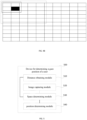
- FIG. 4B is a schematic diagram showing a display screen division process according to FIG. 4A , where the plane shown in FIG. 4B is a plane of the display screen that is subject to gridding processing, and the above-mentioned iterative division scheme can be used to divide the plane.
- the number of hierarchies obtained is 3, where a first hierarchy includes: A area (upper left), B area (lower left), C area (upper right), and D area (lower right).
- the outer dotted line indicates the A area.
- a second hierarchy in the A area includes: A1 sub-area (upper left), A2 sub-area (lower left), A3 sub-area (upper right), and A4 sub-area (lower right).
- the inner dotted line in FIG. 4B represents the A1 sub-area.
- the sub-areas divided in the third hierarchy coincide with the screen area represented by the screen coordinates, which is represented by a black solid rectangular area in the FIG. 4B .
- a training process for the hierarchical coordinate prediction model can be: for certain training data, the user image of user A and the gaze position coordinates of user A on the first hierarchy of the display screen (for example: the position coordinates of the area A may be the position coordinates of the center position of the area within the outermost dotted line) are input to the model for a first training, during implementation, the number of classifications can be reduced by the fully connected layer so that a target dimension is the number of areas divided by the first hierarchy (In this embodiment, there can be four areas (A,B,C,D), that is, the number is 4).
- the user image of user A and the gaze position coordinates of user A on the second hierarchy of the display screen can be input to the model for a second training, during implementation, the number of classifications can be reduced by the fully connected layer so that the target dimension is the number of areas divided by the second hierarchy (in this embodiment, it may be the areas into which the four areas A,B,C,D are divided, respectively, that is, the number is 16).
- the target dimension corresponding to the last hierarchy can be the number of screen coordinates with the smallest unit into which the display screen is divided.
- the initial coordinate prediction model is trained in the above-mentioned training method by means of a plurality of groups of training data similar to the above-mentioned training data to obtain the trained hierarchical coordinate prediction model.
- step 1044 may include: determining a first gaze position by inputting the user image of the target user to the hierarchical coordinate prediction model to obtain the screen coordinates (for example, the screen coordinates corresponding to area A) of the target user on the display screen under the first hierarchy; and determining a second gaze position by inputting the user image of the target user to the hierarchical coordinate prediction model again to obtain the screen coordinates (for example, the screen coordinates corresponding to area B2) of the target user on the display screen under the second hierarchy, and determining the second gaze position as the finally determined gaze position of the user.
- This process can be understood as obtaining an approximate range of the gaze position of the target user after the first input process, and then narrowing down the range layer by layer in the subsequent input processes, and finally obtaining an accurate range.
- the operation cursor on the display screen can be moved to the gaze position.
- the hierarchical coordinate prediction model will sequentially output three screen coordinates, that is, the screen coordinates of the preset position (such as the center position) of the screen area within the outermost dotted line in FIG. 4B , the screen coordinates of the preset position (such as the center position) of the screen area within the innermost dotted line in FIG. 4B , and the screen coordinates of the actual gaze position of the user (the screen coordinates corresponding to the screen area represented by the black rectangular area in FIG.4B ).
- the moving process of the operation cursor will pass through these three screen coordinates in turn.
- the movement of the operation cursor will include a gradual movement trajectory, and it is avoided that the operation cursor jumps directly from the initial position to the gaze position of the user, which improves the aesthetics of interaction and thus improves the user experience.
- the prediction probability of each class of screen label are iteratively calculated layer by layer according to the hierarchy label corresponding to the training data of each output terminal, which can also improve the efficiency of the coordinate prediction model convergence and reduce the parallelism of the coordinate prediction model training process.
- the target distance from the display screen to the target user can be obtained, and the user image of the target user can be obtained, where the user image includes the global image, the head image, and the eye image, and the global image is the image of the target space in front of the display screen;
- the first space where the eyes of the target user are located is determined from the plurality of preset subspaces within the target space based on the target distance and the global image, and the gaze position of the target user on the display screen corresponding to the first space and the user image of the target user are determined based on the correspondence among the screen coordinates on the display screen and the preset subspaces, the user image.
- the gaze position of the target user can be identified based on the collected user image and the user distance, so that the device cost is reduced while accuracy of identifying the gaze position of the target user is ensured. In this way, the identifying process of the gaze position of the user has good stability and a wide application scope, so that the user has good use experience.
- FIG. 5 is a block diagram showing a device for determining a gaze position of a user according to some embodiments, which is applied to the terminal described in the above application scenarios.
- the device 500 includes a distance obtaining module 510, an image capturing module 520, a space determining module 530 and a position determining module 540.
- the distance obtaining module 510 is configured to obtain a target distance from the display screen to a target user.
- the image capturing module 520 is configured to obtain a user image of the target user.
- the user image includes a global image, a head image, and an eye image, and the global image is an image of the target space in front of the display screen.
- the space determining module 530 is configured to determine a first space where eyes of the target user are located from a plurality of preset subspaces within the target space based on the target distance and the global image.
- the position determining module 540 is configured to determine a gaze position of the target user on the display screen corresponding to the first space and the user image of the target user, based on a preset correspondence among the subspaces, the user image, and screen coordinates on the display screen.
- the position determining module 540 is configured to determine screen coordinates on the display screen corresponding to the first space and the user image of the target user based on the preset correspondence among the subspaces, the user images, and the screen coordinates on the display screen.
- the display screen is divided into a plurality of sub-areas in advance according to the size of the display screen, and coordinates of a preset position in each of the sub-areas are used as screen coordinates of that sub-area.
- the position determining module 540 can further determine the determined screen coordinates as the gaze position of the target user on the display screen.
- the position determining module 540 is configured to determine a pre-trained coordinate prediction model for the first space; each of the subspaces has a pre-trained coordinate prediction model that has been trained based on the user image and screen coordinates of the gaze position of the user on the display screen, and obtain the screen coordinates on the display screen corresponding to the user image of the target user by inputting the user image of the target user into the coordinate prediction model.
- the following method is used for training the coordinate prediction model constructing an initial coordinate prediction model for each of the subspaces, and obtaining a labeled training data set for the subspace.
- the labeled training data set includes a plurality of groups of training data, and each group of training data includes user image samples of a test user and screen coordinate labels corresponding to the user image samples, and the training data is labeled with the screen coordinate labels.
- the screen coordinate labels represent screen coordinates corresponding to the gaze position of the test user on the display screen when the user image samples are collected
- the user image samples include: global image samples, head image samples, and eye image samples.
- the method can further include inputting the labeled training data set into the initial coordinate prediction model, and comparing an obtained prediction result with the labeled value, and adjusting parameters of the initial coordinate prediction model according to the comparison result until the model converges to obtain the coordinate prediction model which has been trained.
- the following method is used for setting the plurality of subspaces and dividing the target space into the plurality of subspaces according to a shooting angle range and an effective shooting distance of an image capturing device.
- the following method is used for setting the plurality of subspaces and dividing a horizontal shooting angle range of the image capturing device in a horizontal direction at a first preset angle interval to obtain a plurality of first subspaces in the horizontal direction, and dividing a vertical shooting angle range of the image capturing device in a vertical direction at a second preset angle interval to obtain a plurality of second subspaces in the vertical direction.
- the method can additionally include dividing the effective shooting distance of the image capturing device into third subspaces in a from-far-to-near direction at a preset distance interval, and determining subspaces obtained by intersecting and separating the first subspaces, the second subspaces, and the third subspaces as the subspaces into which the target space is divided.
- the space determining module 530 is configured to identify a target partial image from the global image through a preset image recognition algorithm, where the target partial image includes the eyes of the target user, determine plane position information of the eyes of the target user on a first plane according to image position information of the target partial image in the global image, where the first plane and a second plane where the display screen is located are parallel, an determine the first space where the eyes of the target user are located based on the plane position information and the target distance.
- the position determining module 540 is configured to determine a pre-trained hierarchical coordinate prediction model for the first space, where each of the subspaces has a pre-trained hierarchical coordinate prediction model that has been trained based on the user image, screen coordinates of the gaze position of the user on the display screen and a plurality of preset hierarchies, and based on the number of hierarchies corresponding to the hierarchical coordinate prediction model, inputting the user image of the target user into the hierarchical coordinate prediction model for several times, and obtaining the gaze position of the target user on the display screen under the corresponding hierarchy for each time.
- the larger the number of hierarchies the more sub-areas into which the display screen is divided.
- the target distance from the display screen to the target user can be obtained, and the user image of the target user can be obtained, and the user image includes the global image, the head image, and the eye image, and the global image is an image of target space in front of the display screen.
- the first space where the eyes of the target user are located is determined from the plurality of preset subspaces within the target space based on the target distance and the global image; and the gaze position of the target user on the display screen corresponding to the first space and the user image of the target user is determined based on the preset correspondence among the subspaces, the user image, and the screen coordinates on the display screen.
- the gaze position of the target user can be identified based on the collected user image and the user distance, so that the device cost is reduced while accuracy of identifying the gaze position of the target user is ensured. In this way, the identifying process of the gaze position of the user has good stability and a wide application scope, so that the user has good use experience.
- FIG. 6 is a block diagram showing an electronic apparatus according to some embodiments.
- the electronic apparatus 600 may be, for example, a smart TV, a mobile phone, a computer, a digital broadcasting terminal, a messaging device, a game console, a tablet device, a medical device, a fitness device, a personal digital assistant, and other terminals.
- the electronic apparatus 600 may include one or more of the following components: a processing component 602, a memory 604, a power component 606, a multimedia component 608, an audio component 610, an input/output (I/O) interface 612, a sensor component 614, and a communication component 616.
- a processing component 602 a memory 604, a power component 606, a multimedia component 608, an audio component 610, an input/output (I/O) interface 612, a sensor component 614, and a communication component 616.
- the processing component 602 typically controls the overall operations of the electronic apparatus 600, such as the operations associated with display, telephone calls, data communications, camera operations, and recording operations.
- the processing component 602 can include one or more processors 620 to execute instructions to perform all or part of the steps in the above described methods.
- the processing component 602 can include one or more modules to facilitate the interaction between the processing component 602 and other components.
- the processing component 602 can include a multimedia module to facilitate the interaction between the multimedia component 608 and the processing component 602.
- the processor can execute any of the above mentioned method for determining a gaze position of the user.
- the memory 604 is configured to store various types of data to support the operation of the electronic apparatus 600. Examples of such data include instructions for any application or method operated on apparatus 600, such as the contact data, the phone book data, messages, pictures, videos, and the like.
- the memory 604 can be implemented by any type of volatile or non-volatile storage device, or a combination of volatile storage device and non-volatile storage device, such as a static random access memory (SRAM), an electrically erasable programmable read-only memory (EEPROM), an erasable programmable read-only memory (EPROM), a programmable read-only memory (PROM), a read-only memory (ROM), a magnetic memory, a flash memory, a magnetic or optical disk.
- SRAM static random access memory
- EEPROM electrically erasable programmable read-only memory
- EPROM erasable programmable read-only memory
- PROM programmable read-only memory
- ROM read-only memory
- magnetic memory a magnetic memory
- the power component 606 provides power to various components of the electronic apparatus 600.
- the power component 606 can include a power management system, one or more power sources, and other components associated with the generation, management, and distribution of power in the electronic apparatus 600.
- the multimedia component 608 includes a screen providing an output interface between the electronic apparatus 600 and the user.
- the screen can include a liquid crystal display (LCD) and a touch panel (TP). If the screen includes the touch panel, the screen can be implemented as a touch screen to receive input signals from the user.
- the touch panel includes one or more touch sensors to sense touches, swipes, and gestures on the touch panel. The touch sensors may not only sense a boundary of a touch or swipe action, but also sense a period of time and a pressure associated with the touch or swipe action.
- the multimedia component 608 includes a front camera and/or a rear camera.
- the front camera and/or the rear camera can receive external multimedia datum.
- the front camera and the rear camera may be a fixed optical lens system or have focus and optical zoom capability.
- the audio component 610 is configured to output and/or input an audio signal.
- the audio component 610 includes a microphone (MIC) configured to receive an external audio signal when the electronic apparatus 600 is in an operation mode, such as a call mode, a recording mode, and a voice recognition mode.
- the received audio signal may be further stored in the memory 604 or sent via the communication component 616.
- the audio component 610 also includes a speaker for outputting the audio signal.
- the I/O interface 612 provides an interface between the processing component 602 and peripheral interface modules, such as a keyboard, a click wheel, buttons, and the like. These buttons may include, but are not limited to, a home button, a volume button, a starting button, and a locking button.
- the sensor component 614 includes one or more sensors for providing status assessments of various aspects of the electronic apparatus 600.
- the sensor component 614 can detect an open/closed status of the electronic apparatus 600, relative positioning of components, such as the display and the keypad of the electronic apparatus 600.
- the sensor component 614 can also detect a change in position of one component of the electronic apparatus 600 or the electronic apparatus 600, the presence or absence of user contact with the electronic apparatus 600, an orientation, or an acceleration/deceleration of the electronic apparatus 600, and a change in temperature of the electronic apparatus 600.
- the sensor component 614 can include a proximity sensor configured to detect the presence of nearby objects without any physical contact.
- the sensor component 614 can also include a light sensor, such as a CMOS or CCD image sensor, configured to use in imaging applications.
- the sensor component 614 can also include an accelerometer sensor, a gyroscope sensor, a magnetic sensor, a pressure sensor, or a temperature sensor.
- the communication component 616 is configured to facilitate wired or wireless communication between the electronic apparatus 600 and other devices.
- the electronic apparatus 600 can access a wireless network based on any communication standard, such as Wi-Fi, 2G or 3G, or a combination of 2G and 3G.
- the communication component 616 receives broadcast signals or broadcast associated information from an external broadcast management system via a broadcast channel.
- the communication component 616 also includes a near field communication (NFC) module to facilitate short-range communications.
- the NFC module can be implemented based on a radio frequency identification (RFID) technology, an infrared data association (IrDA) technology, an ultra-wideband (UWB) technology, a Bluetooth (BT) technology, and other technologies.
- RFID radio frequency identification
- IrDA infrared data association
- UWB ultra-wideband
- BT Bluetooth
- the electronic apparatus 600 may be implemented with one or more application specific integrated circuits (ASICs), digital signal processors (DSPs), digital signal processing devices (DSPDs), programmable logic devices (PLDs), field programmable Gate array (FPGA), controller, microcontroller, microprocessor or other electronic components.
- ASICs application specific integrated circuits
- DSPs digital signal processors
- DSPDs digital signal processing devices
- PLDs programmable logic devices
- FPGA field programmable Gate array
- controller microcontroller, microprocessor or other electronic components.
- non-transitory computer-readable storage medium including instructions, such as a memory 604 including instructions executable by the processor 620 of the electronic apparatus 600 to perform the above described method.
- the non-transitory computer readable storage medium may be a ROM, a random access memory (RAM), a CD-ROM, a magnetic tape, a floppy disc, and an optical data storage device.
- the computer program product includes a computer program that can be executed by a programmable device.
- the computer program has a code portion for executing the above-mentioned method for determining a gaze position of a user when executed by the programmable device
- the present disclosure can identify the gaze position of the user based on the collected user image and the user distance, so that the device cost is reduced while accuracy of identifying the gaze position of the target user is ensured. In this way, the identifying process of the gaze position of the user has good stability and a wide application scope, so that the user has good use experience.
Landscapes
- Engineering & Computer Science (AREA)
- Theoretical Computer Science (AREA)
- Physics & Mathematics (AREA)
- General Engineering & Computer Science (AREA)
- General Physics & Mathematics (AREA)
- Human Computer Interaction (AREA)
- Data Mining & Analysis (AREA)
- General Health & Medical Sciences (AREA)
- Health & Medical Sciences (AREA)
- Life Sciences & Earth Sciences (AREA)
- Artificial Intelligence (AREA)
- Evolutionary Computation (AREA)
- Software Systems (AREA)
- Mathematical Physics (AREA)
- Biomedical Technology (AREA)
- Biophysics (AREA)
- Computational Linguistics (AREA)
- Multimedia (AREA)
- Molecular Biology (AREA)
- Computing Systems (AREA)
- Bioinformatics & Computational Biology (AREA)
- Evolutionary Biology (AREA)
- Bioinformatics & Cheminformatics (AREA)
- Computer Vision & Pattern Recognition (AREA)
- Oral & Maxillofacial Surgery (AREA)
- Ophthalmology & Optometry (AREA)
- User Interface Of Digital Computer (AREA)
- Image Analysis (AREA)
- Processing Or Creating Images (AREA)
Claims (13)
- Méthode de détermination de la position du regard d'un utilisateur appliquée à un terminal doté d'un écran d'affichage, caractérisée par le fait que la méthode comprend :obtenir une distance cible entre l'écran d'affichage et un utilisateur cible (101) ;obtenir une image de l'utilisateur cible (102), l'image de l'utilisateur comprenant une image globale, une image de la tête et une image des yeux, l'image globale étant une image de l'espace cible devant l'écran d'affichage ;déterminer un premier espace où les yeux de l'utilisateur cible sont situés à partir d'une pluralité de sous-espaces prédéfinis dans l'espace cible sur la base de la distance cible et de l'image globale (103) ; etdéterminer la position du regard de l'utilisateur cible sur l'écran d'affichage correspondant au premier espace et à l'image de l'utilisateur cible sur la base d'une correspondance prédéfinie entre les sous-espaces, les images de l'utilisateur et les coordonnées de l'écran d'affichage (104),dans lequel la détermination de la position du regard de l'utilisateur cible sur l'écran d'affichage (104) est en outre caractérisée en ce qu'elle comprend :déterminer un modèle de prédiction de coordonnées hiérarchiques pré-entraîné pour le premier espace qui a été entraîné (1043), où chacun des sous-espaces a un modèle de prédiction de coordonnées hiérarchiques pré-entraîné qui a été entraîné sur la base des images de l'utilisateur, des coordonnées d'écran de la position du regard de l'utilisateur sur l'écran d'affichage, et d'une pluralité de hiérarchies prédéfinies ; etobtenir la position du regard de l'utilisateur cible sur l'écran d'affichage sous une hiérarchie correspondante à chaque fois en entrant l'image de l'utilisateur cible dans le modèle de prédiction des coordonnées hiérarchiques plusieurs fois sur la base du nombre de hiérarchies correspondant au modèle de prédiction des coordonnées hiérarchiques (1044);l'augmentation du nombre de sous-zones dans lesquelles l'écran d'affichage est divisé augmente le nombre de la hiérarchie,dans lequel une i-ième hiérarchie du module comprend :diviser une zone de sortie d'une (i-1)-ième hiérarchie du module en N i-ième zones hiérarchiques, la zone de sortie de la (i-1)-ième hiérarchie étant déterminée à partir de N (i-1)-ième zones hiérarchiques correspondant à la (i-1)-ième hiérarchie de l'écran d'affichage ; etdéterminer une zone parmi les N zones de la i-ième hiérarchie en tant que sortie de la i-ième hiérarchie du module, i étant un nombre entier supérieur à 2.
- Méthode selon la revendication 1, dans laquelle la détermination de la position du regard de l'utilisateur cible (104) comprend en outre :déterminer les coordonnées de l'écran d'affichage correspondant au premier espace et à l'image de l'utilisateur cible sur la base de la correspondance prédéfinie entre les sous-espaces, les images de l'utilisateur et les coordonnées de l'écran d'affichage (1041), l'écran d'affichage étant divisé à l'avance en plusieurs sous-zones sur la base d'une taille de l'écran d'affichage, et les coordonnées d'une position prédéfinie dans chacune des sous-zones étant utilisées comme coordonnées de l'écran de la sous-zone ; etdéterminer les coordonnées d'écran déterminées comme étant la position du regard de l'utilisateur cible sur l'écran d'affichage (1042).
- Méthode selon la revendication 2, dans laquelle la détermination des coordonnées de l'écran sur l'écran d'affichage correspondant au premier espace et à l'image de l'utilisateur cible (1041) comprend en outre :déterminer un modèle de prédiction de coordonnées pré-entraîné pour le premier espace, où chacun des sous-espaces a un modèle de prédiction de coordonnées pré-entraîné qui a été entraîné sur la base des images de l'utilisateur et des coordonnées d'écran de la position du regard de l'utilisateur sur l'écran d'affichage ; etobtenir les coordonnées de l'écran d'affichage correspondant à l'image de l'utilisateur cible en introduisant l'image de l'utilisateur cible dans le modèle de prédiction des coordonnées.
- Méthode selon la revendication 3, dans laquelle le modèle de prédiction des coordonnées est obtenu par :construire un modèle initial de prédiction des coordonnées pour chacun des sous-espaces ;obtenir un ensemble de données d'entraînement étiquetées pour le sous-espace, l'ensemble de données d'entraînement é tiquet é es comprenant une pluralité de groupes de données d'entraînement qui incluent chacun : un échantillon d'images d'un utilisateur testé et une étiquette de coordonnées d'écran correspondant à l'échantillon d'images de l'utilisateur, les données d'entraînement étant étiquetées avec l'étiquette de coordonnées d'écran ; lorsque l'échantillon d'images de l'utilisateur est collecté pour chacun des sous-espaces, les yeux de l'utilisateur testé se trouvent dans ce sous-espace ; l'étiquette de coordonnées d'écran représente les coordonnées d'écran correspondant à la position du regard de l'utilisateur testé sur l'écran d'affichage lorsque l'échantillon d'images de l'utilisateur est collecté, et l'échantillon d'images de l'utilisateur comprend un échantillon d'images globales, un échantillon d'images de la tête et un échantillon d'images de l'oeil ;obtenir un résultat de prédiction en introduisant l'ensemble de données d'entraînement é tiquetées dans le modèle de prédiction des coordonnées initiales ; etobtenir le modèle de prédiction de coordonnées pré-entraîné en ajustant, sur la base d'une comparaison entre le résultat de prédiction obtenu et une valeur étiquetée, les paramètres du modèle initial de prédiction de coordonnées jusqu'à ce que le modèle converge.
- Méthode selon l'une des revendications précédentes, dans laquelle la pluralité de sous-espaces est définie par :
diviser l'espace cible en plusieurs sous-espaces en fonction d'un angle de prise de vue et d'une distance de prise de vue effective d'un dispositif de capture d'images. - Méthode selon la revendication 5, dans laquelle la pluralité de sous-espaces est définie par :obtenir une pluralité de premiers sous-espaces dans la direction horizontale en divisant une plage d'angles de prise de vue horizontale du dispositif de capture d'images dans une direction horizontale à un premier intervalle d'angle prédéfini ;obtenir une pluralité de seconds sous-espaces dans la direction verticale en divisant une plage d'angles de prise de vue verticale du dispositif de capture d'images dans une direction verticale à un second intervalle d'angle prédéfini ;diviser la distance de prise de vue effective du dispositif de capture d'images en trois sous-espaces dans une direction de loin à près à un intervalle de distance prédéfini ; etdéterminer les sous-espaces obtenus par l'intersection et la séparation des premiers sous-espaces, des deuxièmes sous-espaces et des troisièmes sous-espaces en tant que sous-espaces dans lesquels l'espace cible est divisé.
- Méthode selon l'une des revendications précédentes, dans laquelle la détermination d'un premier espace où se trouvent les yeux de l'utilisateur cible (103) comprend en outre :identifier une image partielle cible à partir de l'image globale au moyen d'un algorithme de reconnaissance d'image prédéfini (1031), l'image partielle cible comprenant les yeux de l'utilisateur cible ;déterminer les informations sur la position des yeux de l'utilisateur cible sur un premier plan en fonction des informations sur la position de l'image partielle cible dans l'image globale (1032), le premier plan et un second plan où se trouve l'écran d'affichage étant parallèles ; etdéterminer le premier espace où se trouvent les yeux de l'utilisateur cible sur la base des informations relatives à la position du plan et de la distance cible (1033).
- Dispositif de détermination de la position du regard d'un utilisateur appliqué à un terminal doté d'un écran d'affichage, caractérisé par le fait que le dispositif comprend un processeur et un dispositif de stockage pour stocker des instructions exécutables par ordinateur qui, lorsqu'elles sont exécutées par le processeur, amènent ce dernier à.. :obtenir une distance cible entre l'écran d'affichage et l'utilisateur cible ;obtenir une image de l'utilisateur cible, l'image de l'utilisateur comprenant une image globale, une image de la tête et une image des yeux, l'image globale étant une image de l'espace cible devant l'écran d'affichage ;déterminer un premier espace où les yeux de l'utilisateur cible sont situés parmi une pluralité de sous-espaces prédéfinis dans l'espace cible sur la base de la distance cible et de l'image globale ; etdéterminer la position du regard de l'utilisateur cible sur l'écran d'affichage correspondant au premier espace et à l'image de l'utilisateur cible, sur la base d'une correspondance prédéfinie entre les sous-espaces, les images de l'utilisateur et les coordonnées de l'écran d'affichage,le dispositif est en outre caractérisé par le fait quele processeur est configuré pour :déterminer un modèle de prédiction de coordonnées hiérarchiques pré-entraîné pour le premier espace, où chacun des sous-espaces a un modèle de prédiction de coordonnées hiérarchiques pré-entraîné qui a été entraîné sur la base des images de l'utilisateur, des coordonnées d'écran de la position du regard de l'utilisateur sur l'écran d'affichage, et d'une pluralité de hiérarchies pré-établies ; etobtenir la position du regard de l'utilisateur cible sur l'écran d'affichage selon une hiérarchie correspondante à chaque fois en entrant l'image de l'utilisateur cible dans le modèle de prédiction des coordonnées hiérarchiques plusieurs fois sur la base du nombre de hiérarchies correspondant au modèle de prédiction des coordonnées hiérarchiques,l'augmentation du nombre de sous-zones dans lesquelles l'écran d'affichage est divisé augmente le nombre de la hiérarchie,dans lequel une i-ième hiérarchie du module comprend :diviser une zone de sortie d'une (i-1)-ième hiérarchie du module en N i-ième zones hiérarchiques, la zone de sortie de la (i-1)-ième hiérarchie étant déterminée à partir de N (i-1)-ième zones hiérarchiques correspondant à la (i-1)-ième hiérarchie de l'écran d'affichage ; etdéterminer une zone parmi les N zones de la i-ième hiérarchie en tant que sortie de la i-ième hiérarchie du module, i étant un nombre entier supérieur à 2.
- Dispositif selon la revendication 8, dans lequel le processeur est configuré pour :déterminer les coordonnées de l'écran d'affichage correspondant au premier espace et à l'image de l'utilisateur cible sur la base de la correspondance prédéfinie entre les sous-espaces, les images de l'utilisateur et les coordonnées de l'écran d'affichage, l'écran d'affichage étant divisé à l'avance en plusieurs sous-zones sur la base d'une taille de l'écran d'affichage, et les coordonnées d'une position prédéfinie dans chacune des sous-zones étant utilisées comme coordonnées de l'écran de la sous-zone ; etdéterminer les coordonnées d'écran déterminées comme étant la position du regard de l'utilisateur cible sur l'écran d'affichage ;
- Dispositif selon la revendication 9, dans lequel le processeur est configuré pour :déterminer un modèle de prédiction de coordonnées pré-entraîné pour le premier espace, chacun des sous-espaces ayant un modèle de prédiction de coordonnées pré-entraîné qui a ét é entraîné sur la base des images de l'utilisateur et des coordonnées d'écran de la position du regard de l'utilisateur sur l'écran d'affichage ; etobtenir les coordonnées de l'écran d'affichage correspondant à l'image de l'utilisateur cible en introduisant l'image de l'utilisateur cible dans le modèle de prédiction des coordonnées,dans lequel le modèle de prédiction de coordonnées pré-entraîné est obtenu par :construire un modèle initial de prédiction des coordonnées pour chacun des sous-espaces ;obtenir un ensemble de données d'entraînement étiquetées pour le sous-espace, l'ensemble de données d'entraînement étiquetées comprenant une pluralité de groupes de données d'entraînement, et chaque groupe de données d'entraînement comprend : un échantillon d'image d'un utilisateur test et une étiquette de coordonnées d'écran correspondant à l'échantillon d'image de l'utilisateur, et les données d'entraînement sont étiquetées avec l'étiquette de coordonnées d'écran ; lorsque l'échantillon d'image de l'utilisateur est collecté pour chacun des sous-espaces, les yeux de l'utilisateur test sont dans ce sous-espace ; et l'étiquette de coordonnées d'écran représente les coordonnées d'écran correspondant à la position du regard de l'utilisateur test sur l'écran d'affichage lorsque l'échantillon d'image de l'utilisateur est collecté, et l'échantillon d'image de l'utilisateur comprend : un échantillon d'image globale, un échantillon d'image de tête, et un échantillon d'image d'oeil ;obtenir un résultat de prédiction en introduisant l'ensemble de données d'entraînement étiquetées dans le modèle de prédiction des coordonnées initiales ; etobtenir le modèle de prédiction de coordonnées pré-entraîné en ajustant, sur la base d'une comparaison entre le résultat de prédiction obtenu et une valeur étiquetée, les paramètres du modèle initial de prédiction de coordonnées jusqu'à ce que le modèle initial de prédiction de coordonnées converge.
- Dispositif selon l'une des revendications 8 à 10, dans lequel la pluralité de sous-espaces est définie par :diviser l'espace cible en plusieurs sous-espaces en fonction d'un angle de prise de vue et d'une distance de prise de vue effective d'un dispositif de capture d'images,dans lequel la pluralité de sous-espaces est définie par :obtenir une pluralité de premiers sous-espaces dans la direction horizontale en divisant une plage d'angles de prise de vue horizontale du dispositif de capture d'images dans une direction horizontale à un premier intervalle d'angle prédéfini ;obtenir une pluralité de seconds sous-espaces dans la direction verticale en divisant une plage d'angles de prise de vue verticale du dispositif de capture d'images dans une direction verticale à un second intervalle d'angle prédéfini ;diviser la distance de prise de vue effective du dispositif de capture d'images en trois sous-espaces dans une direction de loin à près à un intervalle de distance prédéfini ; etdéterminer les sous-espaces obtenus par l'intersection et la séparation des premiers sous-espaces, des deuxièmes sous-espaces et des troisièmes sous-espaces en tant que sous-espaces dans lesquels l'espace cible est divisé.
- Dispositif selon l'une des revendications 8 à 11, dans lequel le processeur est configuré pour :identifier une image partielle cible à partir de l'image globale au moyen d'un algorithme de reconnaissance d'image prédéfini, l'image partielle cible comprenant les yeux de l'utilisateur cible ;déterminer les informations sur la position des yeux de l'utilisateur cible sur un premier plan en fonction des informations sur la position de l'image partielle cible dans l'image globale, le premier plan et un second plan où se trouve l'écran d'affichage étant parallèles ; etdéterminer le premier espace où se trouvent les yeux de l'utilisateur cible sur la base des informations relatives à la position du plan et de la distance de la cible.
- Support de stockage lisible par ordinateur sur lequel sont stockées des instructions de programme d'ordinateur, dans lequel les instructions de programme, lorsqu'elles sont exécutées par un processeur, mettent en oeuvre la méthode selon l'une des revendications 1 à 7.
Applications Claiming Priority (1)
| Application Number | Priority Date | Filing Date | Title |
|---|---|---|---|
| CN202010622072.5A CN111881763B (zh) | 2020-06-30 | 2020-06-30 | 确定用户注视位置的方法、装置、存储介质和电子设备 |
Publications (2)
| Publication Number | Publication Date |
|---|---|
| EP3933552A1 EP3933552A1 (fr) | 2022-01-05 |
| EP3933552B1 true EP3933552B1 (fr) | 2024-01-10 |
Family
ID=73157411
Family Applications (1)
| Application Number | Title | Priority Date | Filing Date |
|---|---|---|---|
| EP21166294.5A Active EP3933552B1 (fr) | 2020-06-30 | 2021-03-31 | Procédé et dispositif pour déterminer la position du regard d'un utilisateur, support d'enregistrement et appareil électronique |
Country Status (3)
| Country | Link |
|---|---|
| US (1) | US11868521B2 (fr) |
| EP (1) | EP3933552B1 (fr) |
| CN (1) | CN111881763B (fr) |
Families Citing this family (12)
| Publication number | Priority date | Publication date | Assignee | Title |
|---|---|---|---|---|
| CN114637390A (zh) * | 2020-11-30 | 2022-06-17 | 清华大学 | 内容显示方法及装置 |
| US11474598B2 (en) * | 2021-01-26 | 2022-10-18 | Huawei Technologies Co., Ltd. | Systems and methods for gaze prediction on touch-enabled devices using touch interactions |
| CN113467614A (zh) * | 2021-06-30 | 2021-10-01 | 北京市商汤科技开发有限公司 | 显示界面选择方法及装置 |
| CN113506027A (zh) * | 2021-07-27 | 2021-10-15 | 北京工商大学 | 基于学生视觉注意及教师行为的课程质量评估与提升方法 |
| CN114595323B (zh) * | 2022-03-04 | 2023-03-10 | 北京百度网讯科技有限公司 | 画像构建、推荐、模型训练方法、装置、设备及存储介质 |
| CN117130468A (zh) * | 2022-05-20 | 2023-11-28 | 北京小米移动软件有限公司 | 眼动追踪方法、装置、设备及存储介质 |
| CN114895790B (zh) * | 2022-05-27 | 2026-01-09 | 深圳市立体通技术有限公司 | 一种人机交互方法、装置、电子设备和存储介质 |
| CN116052261B (zh) * | 2022-05-31 | 2025-01-10 | 荣耀终端有限公司 | 视线估计方法及电子设备 |
| CN115359092B (zh) * | 2022-08-19 | 2026-02-10 | 北京百度网讯科技有限公司 | 一种注视点预测模型的训练方法、装置及电子设备 |
| WO2024112872A1 (fr) * | 2022-11-22 | 2024-05-30 | Linus Health, Inc. | Procédés de suivi du regard sans caractéristiques dans des conditions écologiquement valides |
| CN119248101A (zh) * | 2023-07-03 | 2025-01-03 | 北京小米移动软件有限公司 | 设备控制方法、模型训练方法及装置 |
| CN117474984B (zh) * | 2023-12-27 | 2024-04-05 | 凯通科技股份有限公司 | 一种增强现实标签跟踪方法、装置、设备和存储介质 |
Family Cites Families (14)
| Publication number | Priority date | Publication date | Assignee | Title |
|---|---|---|---|---|
| WO2015154882A1 (fr) * | 2014-04-11 | 2015-10-15 | The Eye Tribe Aps | Systèmes et procédés d'étalonnage de suivi oculaire |
| US20150358594A1 (en) * | 2014-06-06 | 2015-12-10 | Carl S. Marshall | Technologies for viewer attention area estimation |
| CN105704369B (zh) * | 2016-01-20 | 2019-02-15 | 努比亚技术有限公司 | 一种信息处理方法及装置、电子设备 |
| GB2578043B (en) * | 2017-06-20 | 2022-06-22 | Nec Corp | Apparatus for providing information and method of providing information, and program |
| CN107728770A (zh) * | 2017-09-26 | 2018-02-23 | 努比亚技术有限公司 | 终端屏幕亮度调整方法、移动终端和计算机可读存储介质 |
| TWI637288B (zh) * | 2017-10-11 | 2018-10-01 | 緯創資通股份有限公司 | 用於眼球視線校正的影像處理方法及其系統 |
| CN108171218A (zh) * | 2018-01-29 | 2018-06-15 | 深圳市唯特视科技有限公司 | 一种基于深度外观注视网络的视线估计方法 |
| CN108369744B (zh) * | 2018-02-12 | 2021-08-24 | 香港应用科技研究院有限公司 | 通过双目单应性映射的3d注视点检测 |
| US10713813B2 (en) * | 2018-02-22 | 2020-07-14 | Innodem Neurosciences | Eye tracking method and system |
| US11113842B2 (en) * | 2018-12-24 | 2021-09-07 | Samsung Electronics Co., Ltd. | Method and apparatus with gaze estimation |
| CN110647790A (zh) * | 2019-04-26 | 2020-01-03 | 北京七鑫易维信息技术有限公司 | 注视信息的确定方法及装置 |
| CN110636218B (zh) * | 2019-08-19 | 2021-05-07 | RealMe重庆移动通信有限公司 | 对焦方法、装置、存储介质及电子设备 |
| CN111046744B (zh) * | 2019-11-21 | 2023-04-18 | 深圳云天励飞技术股份有限公司 | 一种关注区域检测方法、装置、可读存储介质及终端设备 |
| CN111309146B (zh) * | 2020-02-10 | 2022-03-29 | Oppo广东移动通信有限公司 | 图像显示方法及相关产品 |
-
2020
- 2020-06-30 CN CN202010622072.5A patent/CN111881763B/zh active Active
-
2021
- 2021-03-31 EP EP21166294.5A patent/EP3933552B1/fr active Active
- 2021-04-02 US US17/221,427 patent/US11868521B2/en active Active
Also Published As
| Publication number | Publication date |
|---|---|
| US11868521B2 (en) | 2024-01-09 |
| CN111881763B (zh) | 2025-02-11 |
| US20210405742A1 (en) | 2021-12-30 |
| CN111881763A (zh) | 2020-11-03 |
| EP3933552A1 (fr) | 2022-01-05 |
Similar Documents
| Publication | Publication Date | Title |
|---|---|---|
| EP3933552B1 (fr) | Procédé et dispositif pour déterminer la position du regard d'un utilisateur, support d'enregistrement et appareil électronique | |
| US11455491B2 (en) | Method and device for training image recognition model, and storage medium | |
| US11138422B2 (en) | Posture detection method, apparatus and device, and storage medium | |
| CN111368796B (zh) | 人脸图像的处理方法、装置、电子设备及存储介质 | |
| US10007841B2 (en) | Human face recognition method, apparatus and terminal | |
| EP3467707A1 (fr) | Système et procédé pour la reconnaissance des gestes de la main à base d'apprentissage profond en mode immersion | |
| CN107492115B (zh) | 目标对象的检测方法及装置 | |
| CN112115894B (zh) | 手部关键点检测模型的训练方法、装置及电子设备 | |
| WO2020224479A1 (fr) | Procédé et appareil d'acquisition de positions de cible, dispositif informatique, et support d'informations | |
| CN114241604B (zh) | 姿态检测的方法、装置、电子设备和存储介质 | |
| CN108121952A (zh) | 人脸关键点定位方法、装置、设备及存储介质 | |
| US20210065342A1 (en) | Method, electronic device and storage medium for processing image | |
| CN108830219B (zh) | 基于人机交互的目标跟踪方法、装置及存储介质 | |
| WO2012063560A1 (fr) | Système de traitement d'image, procédé de traitement d'image, et support de stockage stockant un programme de traitement d'image | |
| CN112541400B (zh) | 基于视线估计的行为识别方法及装置、电子设备、存储介质 | |
| KR20190109654A (ko) | 심장 박동을 측정하기 위한 전자 장치 및 방법 | |
| CN118377372A (zh) | 基于视线的注视点实时追踪方法、装置、设备及存储介质 | |
| CN113805695A (zh) | 阅读理解水平的预测方法及装置、电子设备和存储介质 | |
| CN112826516A (zh) | 肌电信号处理方法、装置、设备、可读存储介质及产品 | |
| CN112114653B (zh) | 终端设备的操控方法、装置、设备及存储介质 | |
| US9405375B2 (en) | Translation and scale invariant features for gesture recognition | |
| KR102709916B1 (ko) | 복수 객체에 대한 오디오 포커싱 방법 및 장치 | |
| US20230125410A1 (en) | Information processing apparatus, image capturing system, method, and non-transitory computer-readable storage medium | |
| CN114299427B (zh) | 目标对象关键点的检测方法、装置、电子设备及存储介质 | |
| CN107643821B (zh) | 一种输入控制方法、装置及电子设备 |
Legal Events
| Date | Code | Title | Description |
|---|---|---|---|
| PUAI | Public reference made under article 153(3) epc to a published international application that has entered the european phase |
Free format text: ORIGINAL CODE: 0009012 |
|
| STAA | Information on the status of an ep patent application or granted ep patent |
Free format text: STATUS: THE APPLICATION HAS BEEN PUBLISHED |
|
| AK | Designated contracting states |
Kind code of ref document: A1 Designated state(s): AL AT BE BG CH CY CZ DE DK EE ES FI FR GB GR HR HU IE IS IT LI LT LU LV MC MK MT NL NO PL PT RO RS SE SI SK SM TR |
|
| B565 | Issuance of search results under rule 164(2) epc |
Effective date: 20210927 |
|
| STAA | Information on the status of an ep patent application or granted ep patent |
Free format text: STATUS: REQUEST FOR EXAMINATION WAS MADE |
|
| 17P | Request for examination filed |
Effective date: 20220701 |
|
| RBV | Designated contracting states (corrected) |
Designated state(s): AL AT BE BG CH CY CZ DE DK EE ES FI FR GB GR HR HU IE IS IT LI LT LU LV MC MK MT NL NO PL PT RO RS SE SI SK SM TR |
|
| GRAJ | Information related to disapproval of communication of intention to grant by the applicant or resumption of examination proceedings by the epo deleted |
Free format text: ORIGINAL CODE: EPIDOSDIGR1 |
|
| STAA | Information on the status of an ep patent application or granted ep patent |
Free format text: STATUS: GRANT OF PATENT IS INTENDED |
|
| GRAP | Despatch of communication of intention to grant a patent |
Free format text: ORIGINAL CODE: EPIDOSNIGR1 |
|
| RIC1 | Information provided on ipc code assigned before grant |
Ipc: G06N 3/045 20230101ALI20230731BHEP Ipc: G06N 3/08 20060101ALI20230731BHEP Ipc: G06N 3/02 20060101ALI20230731BHEP Ipc: G06F 3/03 20060101ALI20230731BHEP Ipc: G06F 3/01 20060101AFI20230731BHEP |
|
| INTG | Intention to grant announced |
Effective date: 20230814 |
|
| RIN1 | Information on inventor provided before grant (corrected) |
Inventor name: HE, LI |
|
| P01 | Opt-out of the competence of the unified patent court (upc) registered |
Effective date: 20230925 |
|
| GRAS | Grant fee paid |
Free format text: ORIGINAL CODE: EPIDOSNIGR3 |
|
| GRAA | (expected) grant |
Free format text: ORIGINAL CODE: 0009210 |
|
| STAA | Information on the status of an ep patent application or granted ep patent |
Free format text: STATUS: THE PATENT HAS BEEN GRANTED |
|
| AK | Designated contracting states |
Kind code of ref document: B1 Designated state(s): AL AT BE BG CH CY CZ DE DK EE ES FI FR GB GR HR HU IE IS IT LI LT LU LV MC MK MT NL NO PL PT RO RS SE SI SK SM TR |
|
| REG | Reference to a national code |
Ref country code: GB Ref legal event code: FG4D |
|
| REG | Reference to a national code |
Ref country code: CH Ref legal event code: EP |
|
| REG | Reference to a national code |
Ref country code: DE Ref legal event code: R096 Ref document number: 602021008429 Country of ref document: DE |
|
| REG | Reference to a national code |
Ref country code: IE Ref legal event code: FG4D |
|
| REG | Reference to a national code |
Ref country code: LT Ref legal event code: MG9D |
|
| REG | Reference to a national code |
Ref country code: NL Ref legal event code: MP Effective date: 20240110 |
|
| REG | Reference to a national code |
Ref country code: AT Ref legal event code: MK05 Ref document number: 1649416 Country of ref document: AT Kind code of ref document: T Effective date: 20240110 |
|
| PG25 | Lapsed in a contracting state [announced via postgrant information from national office to epo] |
Ref country code: NL Free format text: LAPSE BECAUSE OF FAILURE TO SUBMIT A TRANSLATION OF THE DESCRIPTION OR TO PAY THE FEE WITHIN THE PRESCRIBED TIME-LIMIT Effective date: 20240110 |
|
| PG25 | Lapsed in a contracting state [announced via postgrant information from national office to epo] |
Ref country code: NL Free format text: LAPSE BECAUSE OF FAILURE TO SUBMIT A TRANSLATION OF THE DESCRIPTION OR TO PAY THE FEE WITHIN THE PRESCRIBED TIME-LIMIT Effective date: 20240110 |
|
| PG25 | Lapsed in a contracting state [announced via postgrant information from national office to epo] |
Ref country code: IS Free format text: LAPSE BECAUSE OF FAILURE TO SUBMIT A TRANSLATION OF THE DESCRIPTION OR TO PAY THE FEE WITHIN THE PRESCRIBED TIME-LIMIT Effective date: 20240510 |
|
| PG25 | Lapsed in a contracting state [announced via postgrant information from national office to epo] |
Ref country code: LT Free format text: LAPSE BECAUSE OF FAILURE TO SUBMIT A TRANSLATION OF THE DESCRIPTION OR TO PAY THE FEE WITHIN THE PRESCRIBED TIME-LIMIT Effective date: 20240110 |
|
| PG25 | Lapsed in a contracting state [announced via postgrant information from national office to epo] |
Ref country code: GR Free format text: LAPSE BECAUSE OF FAILURE TO SUBMIT A TRANSLATION OF THE DESCRIPTION OR TO PAY THE FEE WITHIN THE PRESCRIBED TIME-LIMIT Effective date: 20240411 |
|
| PG25 | Lapsed in a contracting state [announced via postgrant information from national office to epo] |
Ref country code: HR Free format text: LAPSE BECAUSE OF FAILURE TO SUBMIT A TRANSLATION OF THE DESCRIPTION OR TO PAY THE FEE WITHIN THE PRESCRIBED TIME-LIMIT Effective date: 20240110 Ref country code: RS Free format text: LAPSE BECAUSE OF FAILURE TO SUBMIT A TRANSLATION OF THE DESCRIPTION OR TO PAY THE FEE WITHIN THE PRESCRIBED TIME-LIMIT Effective date: 20240410 |
|
| PG25 | Lapsed in a contracting state [announced via postgrant information from national office to epo] |
Ref country code: ES Free format text: LAPSE BECAUSE OF FAILURE TO SUBMIT A TRANSLATION OF THE DESCRIPTION OR TO PAY THE FEE WITHIN THE PRESCRIBED TIME-LIMIT Effective date: 20240110 |
|
| PG25 | Lapsed in a contracting state [announced via postgrant information from national office to epo] |
Ref country code: AT Free format text: LAPSE BECAUSE OF FAILURE TO SUBMIT A TRANSLATION OF THE DESCRIPTION OR TO PAY THE FEE WITHIN THE PRESCRIBED TIME-LIMIT Effective date: 20240110 |
|
| PG25 | Lapsed in a contracting state [announced via postgrant information from national office to epo] |
Ref country code: RS Free format text: LAPSE BECAUSE OF FAILURE TO SUBMIT A TRANSLATION OF THE DESCRIPTION OR TO PAY THE FEE WITHIN THE PRESCRIBED TIME-LIMIT Effective date: 20240410 Ref country code: NO Free format text: LAPSE BECAUSE OF FAILURE TO SUBMIT A TRANSLATION OF THE DESCRIPTION OR TO PAY THE FEE WITHIN THE PRESCRIBED TIME-LIMIT Effective date: 20240410 Ref country code: LT Free format text: LAPSE BECAUSE OF FAILURE TO SUBMIT A TRANSLATION OF THE DESCRIPTION OR TO PAY THE FEE WITHIN THE PRESCRIBED TIME-LIMIT Effective date: 20240110 Ref country code: IS Free format text: LAPSE BECAUSE OF FAILURE TO SUBMIT A TRANSLATION OF THE DESCRIPTION OR TO PAY THE FEE WITHIN THE PRESCRIBED TIME-LIMIT Effective date: 20240510 Ref country code: HR Free format text: LAPSE BECAUSE OF FAILURE TO SUBMIT A TRANSLATION OF THE DESCRIPTION OR TO PAY THE FEE WITHIN THE PRESCRIBED TIME-LIMIT Effective date: 20240110 Ref country code: GR Free format text: LAPSE BECAUSE OF FAILURE TO SUBMIT A TRANSLATION OF THE DESCRIPTION OR TO PAY THE FEE WITHIN THE PRESCRIBED TIME-LIMIT Effective date: 20240411 Ref country code: ES Free format text: LAPSE BECAUSE OF FAILURE TO SUBMIT A TRANSLATION OF THE DESCRIPTION OR TO PAY THE FEE WITHIN THE PRESCRIBED TIME-LIMIT Effective date: 20240110 Ref country code: BG Free format text: LAPSE BECAUSE OF FAILURE TO SUBMIT A TRANSLATION OF THE DESCRIPTION OR TO PAY THE FEE WITHIN THE PRESCRIBED TIME-LIMIT Effective date: 20240110 Ref country code: AT Free format text: LAPSE BECAUSE OF FAILURE TO SUBMIT A TRANSLATION OF THE DESCRIPTION OR TO PAY THE FEE WITHIN THE PRESCRIBED TIME-LIMIT Effective date: 20240110 |
|
| PG25 | Lapsed in a contracting state [announced via postgrant information from national office to epo] |
Ref country code: PT Free format text: LAPSE BECAUSE OF FAILURE TO SUBMIT A TRANSLATION OF THE DESCRIPTION OR TO PAY THE FEE WITHIN THE PRESCRIBED TIME-LIMIT Effective date: 20240510 Ref country code: PL Free format text: LAPSE BECAUSE OF FAILURE TO SUBMIT A TRANSLATION OF THE DESCRIPTION OR TO PAY THE FEE WITHIN THE PRESCRIBED TIME-LIMIT Effective date: 20240110 |
|
| PG25 | Lapsed in a contracting state [announced via postgrant information from national office to epo] |
Ref country code: SE Free format text: LAPSE BECAUSE OF FAILURE TO SUBMIT A TRANSLATION OF THE DESCRIPTION OR TO PAY THE FEE WITHIN THE PRESCRIBED TIME-LIMIT Effective date: 20240110 Ref country code: PT Free format text: LAPSE BECAUSE OF FAILURE TO SUBMIT A TRANSLATION OF THE DESCRIPTION OR TO PAY THE FEE WITHIN THE PRESCRIBED TIME-LIMIT Effective date: 20240510 Ref country code: PL Free format text: LAPSE BECAUSE OF FAILURE TO SUBMIT A TRANSLATION OF THE DESCRIPTION OR TO PAY THE FEE WITHIN THE PRESCRIBED TIME-LIMIT Effective date: 20240110 Ref country code: LV Free format text: LAPSE BECAUSE OF FAILURE TO SUBMIT A TRANSLATION OF THE DESCRIPTION OR TO PAY THE FEE WITHIN THE PRESCRIBED TIME-LIMIT Effective date: 20240110 |
|
| PG25 | Lapsed in a contracting state [announced via postgrant information from national office to epo] |
Ref country code: DK Free format text: LAPSE BECAUSE OF FAILURE TO SUBMIT A TRANSLATION OF THE DESCRIPTION OR TO PAY THE FEE WITHIN THE PRESCRIBED TIME-LIMIT Effective date: 20240110 |
|
| REG | Reference to a national code |
Ref country code: DE Ref legal event code: R097 Ref document number: 602021008429 Country of ref document: DE |
|
| PG25 | Lapsed in a contracting state [announced via postgrant information from national office to epo] |
Ref country code: SM Free format text: LAPSE BECAUSE OF FAILURE TO SUBMIT A TRANSLATION OF THE DESCRIPTION OR TO PAY THE FEE WITHIN THE PRESCRIBED TIME-LIMIT Effective date: 20240110 |
|
| PG25 | Lapsed in a contracting state [announced via postgrant information from national office to epo] |
Ref country code: CZ Free format text: LAPSE BECAUSE OF FAILURE TO SUBMIT A TRANSLATION OF THE DESCRIPTION OR TO PAY THE FEE WITHIN THE PRESCRIBED TIME-LIMIT Effective date: 20240110 Ref country code: EE Free format text: LAPSE BECAUSE OF FAILURE TO SUBMIT A TRANSLATION OF THE DESCRIPTION OR TO PAY THE FEE WITHIN THE PRESCRIBED TIME-LIMIT Effective date: 20240110 |
|
| PG25 | Lapsed in a contracting state [announced via postgrant information from national office to epo] |
Ref country code: SK Free format text: LAPSE BECAUSE OF FAILURE TO SUBMIT A TRANSLATION OF THE DESCRIPTION OR TO PAY THE FEE WITHIN THE PRESCRIBED TIME-LIMIT Effective date: 20240110 |
|
| PG25 | Lapsed in a contracting state [announced via postgrant information from national office to epo] |
Ref country code: SM Free format text: LAPSE BECAUSE OF FAILURE TO SUBMIT A TRANSLATION OF THE DESCRIPTION OR TO PAY THE FEE WITHIN THE PRESCRIBED TIME-LIMIT Effective date: 20240110 Ref country code: SK Free format text: LAPSE BECAUSE OF FAILURE TO SUBMIT A TRANSLATION OF THE DESCRIPTION OR TO PAY THE FEE WITHIN THE PRESCRIBED TIME-LIMIT Effective date: 20240110 Ref country code: RO Free format text: LAPSE BECAUSE OF FAILURE TO SUBMIT A TRANSLATION OF THE DESCRIPTION OR TO PAY THE FEE WITHIN THE PRESCRIBED TIME-LIMIT Effective date: 20240110 Ref country code: EE Free format text: LAPSE BECAUSE OF FAILURE TO SUBMIT A TRANSLATION OF THE DESCRIPTION OR TO PAY THE FEE WITHIN THE PRESCRIBED TIME-LIMIT Effective date: 20240110 Ref country code: DK Free format text: LAPSE BECAUSE OF FAILURE TO SUBMIT A TRANSLATION OF THE DESCRIPTION OR TO PAY THE FEE WITHIN THE PRESCRIBED TIME-LIMIT Effective date: 20240110 Ref country code: CZ Free format text: LAPSE BECAUSE OF FAILURE TO SUBMIT A TRANSLATION OF THE DESCRIPTION OR TO PAY THE FEE WITHIN THE PRESCRIBED TIME-LIMIT Effective date: 20240110 |
|
| REG | Reference to a national code |
Ref country code: CH Ref legal event code: PL |
|
| PLBE | No opposition filed within time limit |
Free format text: ORIGINAL CODE: 0009261 |
|
| STAA | Information on the status of an ep patent application or granted ep patent |
Free format text: STATUS: NO OPPOSITION FILED WITHIN TIME LIMIT |
|
| PG25 | Lapsed in a contracting state [announced via postgrant information from national office to epo] |
Ref country code: LU Free format text: LAPSE BECAUSE OF NON-PAYMENT OF DUE FEES Effective date: 20240331 |
|
| PG25 | Lapsed in a contracting state [announced via postgrant information from national office to epo] |
Ref country code: MC Free format text: LAPSE BECAUSE OF FAILURE TO SUBMIT A TRANSLATION OF THE DESCRIPTION OR TO PAY THE FEE WITHIN THE PRESCRIBED TIME-LIMIT Effective date: 20240110 |
|
| PG25 | Lapsed in a contracting state [announced via postgrant information from national office to epo] |
Ref country code: MC Free format text: LAPSE BECAUSE OF FAILURE TO SUBMIT A TRANSLATION OF THE DESCRIPTION OR TO PAY THE FEE WITHIN THE PRESCRIBED TIME-LIMIT Effective date: 20240110 Ref country code: LU Free format text: LAPSE BECAUSE OF NON-PAYMENT OF DUE FEES Effective date: 20240331 |
|
| PG25 | Lapsed in a contracting state [announced via postgrant information from national office to epo] |
Ref country code: IT Free format text: LAPSE BECAUSE OF FAILURE TO SUBMIT A TRANSLATION OF THE DESCRIPTION OR TO PAY THE FEE WITHIN THE PRESCRIBED TIME-LIMIT Effective date: 20240110 |
|
| REG | Reference to a national code |
Ref country code: BE Ref legal event code: MM Effective date: 20240331 |
|
| 26N | No opposition filed |
Effective date: 20241011 |
|
| PG25 | Lapsed in a contracting state [announced via postgrant information from national office to epo] |
Ref country code: IT Free format text: LAPSE BECAUSE OF FAILURE TO SUBMIT A TRANSLATION OF THE DESCRIPTION OR TO PAY THE FEE WITHIN THE PRESCRIBED TIME-LIMIT Effective date: 20240110 |
|
| PG25 | Lapsed in a contracting state [announced via postgrant information from national office to epo] |
Ref country code: BE Free format text: LAPSE BECAUSE OF NON-PAYMENT OF DUE FEES Effective date: 20240331 |
|
| PG25 | Lapsed in a contracting state [announced via postgrant information from national office to epo] |
Ref country code: IE Free format text: LAPSE BECAUSE OF NON-PAYMENT OF DUE FEES Effective date: 20240331 |
|
| PG25 | Lapsed in a contracting state [announced via postgrant information from national office to epo] |
Ref country code: IE Free format text: LAPSE BECAUSE OF NON-PAYMENT OF DUE FEES Effective date: 20240331 Ref country code: BE Free format text: LAPSE BECAUSE OF NON-PAYMENT OF DUE FEES Effective date: 20240331 Ref country code: CH Free format text: LAPSE BECAUSE OF NON-PAYMENT OF DUE FEES Effective date: 20240331 |
|
| PG25 | Lapsed in a contracting state [announced via postgrant information from national office to epo] |
Ref country code: SI Free format text: LAPSE BECAUSE OF FAILURE TO SUBMIT A TRANSLATION OF THE DESCRIPTION OR TO PAY THE FEE WITHIN THE PRESCRIBED TIME-LIMIT Effective date: 20240110 |
|
| PG25 | Lapsed in a contracting state [announced via postgrant information from national office to epo] |
Ref country code: CY Free format text: LAPSE BECAUSE OF FAILURE TO SUBMIT A TRANSLATION OF THE DESCRIPTION OR TO PAY THE FEE WITHIN THE PRESCRIBED TIME-LIMIT; INVALID AB INITIO Effective date: 20210331 |
|
| PG25 | Lapsed in a contracting state [announced via postgrant information from national office to epo] |
Ref country code: HU Free format text: LAPSE BECAUSE OF FAILURE TO SUBMIT A TRANSLATION OF THE DESCRIPTION OR TO PAY THE FEE WITHIN THE PRESCRIBED TIME-LIMIT; INVALID AB INITIO Effective date: 20210331 |
|
| PG25 | Lapsed in a contracting state [announced via postgrant information from national office to epo] |
Ref country code: FI Free format text: LAPSE BECAUSE OF FAILURE TO SUBMIT A TRANSLATION OF THE DESCRIPTION OR TO PAY THE FEE WITHIN THE PRESCRIBED TIME-LIMIT Effective date: 20240110 |
|
| PG25 | Lapsed in a contracting state [announced via postgrant information from national office to epo] |
Ref country code: TR Free format text: LAPSE BECAUSE OF FAILURE TO SUBMIT A TRANSLATION OF THE DESCRIPTION OR TO PAY THE FEE WITHIN THE PRESCRIBED TIME-LIMIT Effective date: 20240110 |
|
| PGFP | Annual fee paid to national office [announced via postgrant information from national office to epo] |
Ref country code: GB Payment date: 20260209 Year of fee payment: 6 |
|
| PGFP | Annual fee paid to national office [announced via postgrant information from national office to epo] |
Ref country code: DE Payment date: 20260204 Year of fee payment: 6 |
|
| PGFP | Annual fee paid to national office [announced via postgrant information from national office to epo] |
Ref country code: FR Payment date: 20260209 Year of fee payment: 6 |