EP3933466A1 - Optical processing structure of optical fiber - Google Patents
Optical processing structure of optical fiber Download PDFInfo
- Publication number
- EP3933466A1 EP3933466A1 EP20782315.4A EP20782315A EP3933466A1 EP 3933466 A1 EP3933466 A1 EP 3933466A1 EP 20782315 A EP20782315 A EP 20782315A EP 3933466 A1 EP3933466 A1 EP 3933466A1
- Authority
- EP
- European Patent Office
- Prior art keywords
- thermally conductive
- cladding
- optical fiber
- protective material
- conductive protective
- Prior art date
- Legal status (The legal status is an assumption and is not a legal conclusion. Google has not performed a legal analysis and makes no representation as to the accuracy of the status listed.)
- Granted
Links
Images




Classifications
-
- G—PHYSICS
- G02—OPTICS
- G02B—OPTICAL ELEMENTS, SYSTEMS OR APPARATUS
- G02B6/00—Light guides; Structural details of arrangements comprising light guides and other optical elements, e.g. couplings
- G02B6/24—Coupling light guides
- G02B6/241—Light guide terminations
-
- G—PHYSICS
- G02—OPTICS
- G02B—OPTICAL ELEMENTS, SYSTEMS OR APPARATUS
- G02B6/00—Light guides; Structural details of arrangements comprising light guides and other optical elements, e.g. couplings
- G02B6/02—Optical fibres with cladding with or without a coating
- G02B6/02057—Optical fibres with cladding with or without a coating comprising gratings
- G02B6/02076—Refractive index modulation gratings, e.g. Bragg gratings
- G02B6/0208—Refractive index modulation gratings, e.g. Bragg gratings characterised by their structure, wavelength response
- G02B6/021—Refractive index modulation gratings, e.g. Bragg gratings characterised by their structure, wavelength response characterised by the core or cladding or coating, e.g. materials, radial refractive index profiles, cladding shape
- G02B6/02104—Refractive index modulation gratings, e.g. Bragg gratings characterised by their structure, wavelength response characterised by the core or cladding or coating, e.g. materials, radial refractive index profiles, cladding shape characterised by the coating external to the cladding, e.g. coating influences grating properties
-
- G—PHYSICS
- G02—OPTICS
- G02B—OPTICAL ELEMENTS, SYSTEMS OR APPARATUS
- G02B6/00—Light guides; Structural details of arrangements comprising light guides and other optical elements, e.g. couplings
- G02B6/24—Coupling light guides
- G02B6/26—Optical coupling means
- G02B6/28—Optical coupling means having data bus means, i.e. plural waveguides interconnected and providing an inherently bidirectional system by mixing and splitting signals
- G02B6/293—Optical coupling means having data bus means, i.e. plural waveguides interconnected and providing an inherently bidirectional system by mixing and splitting signals with wavelength selective means
- G02B6/29331—Optical coupling means having data bus means, i.e. plural waveguides interconnected and providing an inherently bidirectional system by mixing and splitting signals with wavelength selective means operating by evanescent wave coupling
-
- G—PHYSICS
- G02—OPTICS
- G02B—OPTICAL ELEMENTS, SYSTEMS OR APPARATUS
- G02B6/00—Light guides; Structural details of arrangements comprising light guides and other optical elements, e.g. couplings
- G02B6/24—Coupling light guides
- G02B6/245—Removing protective coverings of light guides before coupling
-
- G—PHYSICS
- G02—OPTICS
- G02B—OPTICAL ELEMENTS, SYSTEMS OR APPARATUS
- G02B6/00—Light guides; Structural details of arrangements comprising light guides and other optical elements, e.g. couplings
- G02B6/44—Mechanical structures for providing tensile strength and external protection for fibres, e.g. optical transmission cables
- G02B6/4401—Optical cables
- G02B6/4402—Optical cables with one single optical waveguide
Definitions
- the present invention relates to an optical processing structure of an optical fiber.
- Patent Literature 1 discloses an optical processing structure in which a host material with a refractive index lower than that of a cladding is provided in a coating removed region of an optical fiber, and a diffuser is added to the host material to scatter and remove cladding mode light, thereby uniformly leak-scattering unwanted cladding mode light while suppressing local heat generation.
- Patent Literature 2 discloses an optical processing structure in which a thermally conductive protective material made of a silicone-based thermally conductive compound is provided at an optical output end of an optical fiber from which a coating has been partially removed, and boron nitride is added as a filler in the thermally conductive protective material.
- Patent Literatures 1 and 2 have the problem that, if there is no filler in the region where evanescent light seeping out of a cladding is present when cladding mode light propagating in the cladding is totally reflected, the cladding mode light is not removed.
- the present invention has been made in consideration of the above, and it is an object of the present invention to provide an optical processing structure of an optical fiber capable of properly removing cladding mode light.
- an optical processing structure of an optical fiber includes: an optical fiber that includes a core, a cladding, and a coating, the coating being partially removed; and a thermally conductive protective material made of a silicone-based thermally conductive compound and provided around the cladding in a coating removed region of the optical fiber.
- the thermally conductive protective material contains a filler having a refractive index higher than a refractive index of the cladding, and the filler is present in a region where evanescent light seeping out of the cladding is present when cladding mode light propagating in the cladding is totally reflected.
- the filler contains either boron nitride or aluminum nitride.
- the thermally conductive protective material further contains an additive that prevents the filler from being present, in the region where evanescent light is present.
- the thermally conductive protective material is made of a substance with a property of decreasing the refractive index as a temperature rises.
- the optical processing structure of the optical fiber according to an embodiment of the present invention further includes a thermally conductive base material on which the optical fiber is placed. Further, the thermally conductive base material has a groove, and an end of the coating in contact with the thermally conductive protective material is accommodated in the groove.
- An optical processing structure of an optical fiber includes: an optical fiber that includes a core, a cladding, and a coating, the coating being partially removed; and a thermally conductive protective material made of a silicone-based thermally conductive compound and provided around the cladding in a coating removed region of the optical fiber.
- the thermally conductive protective material is made of a substance having a refractive index higher than a refractive index of the cladding at room temperature and becomes lower as a temperature rises, and the refractive index of the thermally conductive protective material is lower than the refractive index of the cladding in a given temperature range.
- the thermally conductive protective material contains a filler having a refractive index higher than the refractive index of the cladding, and the filler is present in a region where evanescent light seeping out of the cladding is present when cladding mode light propagating in the cladding is totally reflected.
- the filler contains either boron nitride or aluminum nitride.
- the thermally conductive protective material further contains an additive that prevents the filler from being present, in the region where evanescent light is present.
- the thermally conductive protective material contains a filler with a large diameter and a filler with a small diameter.
- An optical processing structure of an optical fiber includes an optical fiber that includes a core, a cladding, and a coating, the coating being partially removed; and a thermally conductive protective material made of a silicone-based thermally conductive compound and provided around the cladding in a coating removed region of the optical fiber.
- the thermally conductive protective material contains a filler having a refractive index higher than a refractive index of the cladding
- the thermally conductive protective material is a combination of a thermally conductive protective material having a refractive index higher than the refractive index of the cladding at room temperature and a thermally conductive protective material having a refractive index lower than the refractive index of the cladding.
- the filler contains either boron nitride or aluminum nitride.
- a filler with a refractive index higher than that of a cladding is present in a region where evanescent light is present, so that cladding mode light can be properly removed.
- FIG. 1 is a sectional view illustrating a configuration of an optical processing structure of an optical fiber according to the embodiment of the present invention
- FIG. 2 is a cross-sectional view illustrating the optical processing structure of an optical fiber cut at the position of the X-X line in FIG. 1 .
- the optical processing structure of an optical fiber has an optical fiber 10, a thermally conductive protective material 20, and a thermally conductive base material 30 on which the optical fiber 10 and the thermally conductive protective material 20 are placed.
- the optical fiber 10 includes a core 11 located at the center of the optical fiber 10, a cladding 12 covering the outer circumference of the core 11, and a coating 13 covering the outer circumference of the cladding 12.
- Both the core 11 and the cladding 12 are made of quartz-based glass.
- the core 11 is made of quartz glass doped with a dopant, such as germanium (Ge) and fluorine (F), for refractive index adjustment.
- the cladding 12 is made of a substance with a refractive index lower than the maximum refractive index of the core 11.
- the cladding 12 is made of pure quartz glass that does not contain a dopant for refractive index adjustment, for example.
- the optical fiber 10 has a coating removed region 14 where the coating 13 has been partially removed.
- the coating removed region 14 is provided with the thermally conductive protective material 20 that functions as a cladding mode stripper to remove the cladding mode light.
- the thermally conductive protective material 20 is made of a silicone-based thermally conductive compound, for example, and is provided around the cladding 12 in the coating removed region 14.
- the thermally conductive protective material 20 contains a filler with a refractive index higher than that of the cladding 12. This filler contains either boron nitride or aluminum nitride.
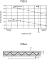
- FIG. 3 is a graph representing the relationship between a temperature and a refractive index of the thermally conductive protective material 20.
- the thermally conductive protective material 20 may be made of a substance (substance A) that has the property of decreasing the refractive index as the temperature rises.
- the thermally conductive protective material 20 may be made of a substance (substance B) that has the property of decreasing the refractive index as the temperature rises, even when the refractive index is higher than that of the cladding 12 (approximately 1.46).
- substance B a substance that has the property of decreasing the refractive index as the temperature rises, even when the refractive index is higher than that of the cladding 12 (approximately 1.46).
- the thermally conductive protective material 20 with a refractive index lower than that of the cladding 12 When the thermally conductive protective material 20 with a refractive index lower than that of the cladding 12 is used to remove the cladding light propagating in the cladding 12, the light removed from the cladding 12 is scattered by the filler in the thermally conductive protective material 20 and returns to the cladding of the optical fiber 10, and therefore, it may be impossible to completely remove the cladding light even if a light removing region is elongated.
- the thermally conductive protective material 20 that has a refractive index higher than that of the cladding 12 at room temperature and the thermally conductive protective material 20 that has a refractive index lower than that of the cladding 12 the cladding light removed from the optical fiber 10 can be removed without returning to the optical fiber 10.
- the thermally conductive base material 30 is made of aluminum with a high thermal conductivity, for example, and functions as a heat sink to dissipate the heat from the optical fiber 10 and the thermally conductive protective material 20.
- a groove 31 of a predetermined depth is formed in a surface of the thermally conductive base material 30.
- the groove 31 accommodates the optical fiber 10 and the thermally conductive protective material 20.
- the groove 31 accommodates the end 13a of the coating 13 that is in contact with the thermally conductive protective material 20.
- FIGS. 4 to 7 The relationship between the cladding mode light propagating in the cladding 12 and the filler contained in the thermally conductive protective material 20 will now be explained with reference to FIGS. 4 to 7 .
- the sectional depiction of each component is omitted.
- the filler contained in the thermally conductive protective material 20 is schematically represented by dot hatching.
- a thermally conductive protective material 121 does not contain any filler at all as illustrated in FIG. 4 .
- the cladding mode light therefore does not radiate outside the cladding 12, but propagates directly in the cladding 12 as represented by the arrow line in FIG. 4 .
- thermally conductive protective material 122 contains a small amount of filler as illustrated in FIG. 5 .
- the cladding mode light collides with the filler in the thermally conductive protective material 122 and scatters as represented by the arrow lines in FIG. 5 , thereby being radiated to the outside of the cladding 12.
- the amount of filler contained in the thermally conductive protective material 122 is small, the amount of filler present in the evanescent region will also be small. Accordingly, in the longitudinal direction of the cladding 12, the cladding mode light propagates over a wide area, and is removed while being uniformly dispersed in the longitudinal direction. This means that the distance necessary to completely remove the cladding mode light becomes longer.
- the thermally conductive protective material 122 decreases in the overall thermal conductivity, thereby resulting in poor heat dissipation compared to the case where the amount of filler is large.
- the amount of filler contained in the thermally conductive protective material 123 is large, the amount of filler present in the evanescent region will also be large. Accordingly, in the longitudinal direction of the cladding 12, the cladding mode light propagates in a narrower area, and is removed on the nearer side than in the case where the amount of filler is small (see FIG. 5 ). This means that the distance necessary to completely remove the cladding mode light becomes shorter. As a result, the thermally conductive protective material 123 generates heat locally, and a resin that constitutes the thermally conductive protective material 123 may deteriorate.
- the thermally conductive protective material 123 improves in the overall thermal conductivity, thereby resulting in better heat dissipation compared to the case where the amount of filler is small.
- the optical processing structure according to the present embodiment is made to achieve both removal of cladding mode light and improvement of heat dissipation, durability, and other properties, by having the filler be present in the evanescent region and controlling the amount of the filler.
- a depth Depth of the evanescent region to which the cladding mode light seeps out of the cladding 12 is calculated in advance, and the amount of filler contained in the region of the thermally conductive protective material 20 corresponding to the calculated depth Depth of the evanescent region is controlled.
- ⁇ is the wavelength of the incident light
- n 1 is the refractive index of the cladding 12
- n 2 is the refractive index of the thermally conductive protective material 20
- ⁇ 12 is the angle of incidence from the cladding 12 to the thermally conductive protective material 20
- NA is the numerical aperture of the optical fiber 10.
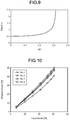
- FIG. 8 is a diagram schematically illustrating the angle of incidence ⁇ 12 from the cladding 12 to the thermally conductive protective material 20, and FIG. 9 is a graph representing the relationship between the numerical aperture NA of the optical fiber 10 and "Depth/ ⁇ ".
- the amount of filler in the evanescent region may be controlled by adjusting the amount of filler contained in the thermally conductive protective material 20 to an appropriate amount, or by adding an additive to the evanescent region to prevent the filler from being present.
- an additive that prevents the filler from being present is added to the evanescent region.
- this inhibiting additive include a fine particle such as AEROSIL (registered trademark).
- the amounts of filler and inhibiting additive to be added to the thermally conductive protective material 20 are determined experimentally in advance.
- a filler with a refractive index higher than that of the cladding 12 is present in the evanescent region in the thermally conductive protective material 20, thereby enabling proper removal of cladding mode light.
- the inhibiting additive is present in the evanescent region in the thermally conductive protective material 20, thereby enabling control of the amount of filler in the evanescent region to an appropriate amount.
- the degree of proximity between the filler and the optical fiber 10 can be adjusted by allowing the inhibiting additive to enter between the filler and the optical fiber 10.
- the inhibiting additive is present in the evanescent region in the thermally conductive protective material 20, so that the cladding mode light can be properly removed with the thermal conductivity of the thermally conductive protective material 20 being maintained.
- a filler with a large diameter e.g., 30 to 50 ⁇ m on average
- a filler with a small diameter e.g., approximately 10 ⁇ m on average
- FIG. 10 is a graph representing the relationship between an amount (concentration) of filler contained in the thermally conductive protective material and the cladding mode light removed from the optical fiber.
- No. 1 is an optical fiber with a thermally conductive protective material containing 20 vol% boron nitride (BN) as a filler
- No. 2 is an optical fiber with a thermally conductive protective material containing 25 vol% boron nitride
- No. 3 is an optical fiber with a thermally conductive protective material containing 30 vol% boron nitride
- No. 4 is an optical fiber with a thermally conductive protective material containing 40 vol% boron nitride.
- Table 1 below also represents the removal gradient of cladding mode light removed from the optical fibers represented in FIG. 10 .
- Table 1 Amount of BN [vol%] Removal gradient No. 1 20 0.69 No. 2 25 0.78 No. 3 30 0.81 No. 4 40 0.83
- cladding mode light escapes more easily in the following order: No. 4 (boron nitride: 40 vol%), No. 3 (boron nitride: 30 vol%), No. 2 (boron nitride: 25 vol%), and No. 1 (boron nitride: 20 vol%).
- the optical processing structure illustrated in FIG. 11 includes an optical fiber 10A from which the coating 13 has been partially removed, an optical fiber 10B from which the coating 13 has been partially removed, the thermally conductive protective material 20, and the thermally conductive base material 30.
- the optical fiber 10A includes a small-diameter core 11A located at the center of the optical fiber 10A, a cladding 12A covering the outer circumference of the core 11A, and a coating 13 covering the outer circumference of the cladding 12A.
- the optical fiber 10B includes a largediameter core 11B located at the center of the optical fiber 10B, a cladding 12B covering the outer circumference of the core 11B, and a coating 13 covering the outer circumference of the cladding 12B.
- the optical fibers 10A and 10B are fused together at part A in FIG. 11 .
- the outer circumferences of the claddings 12A, 12B in the coating removed region 14 may be formed in a tapered shape. By forming the outer circumferences of the claddings 12A, 12B in the coating removed region 14 in a tapered shape, the cladding mode light escapes more easily out of the claddings 12A, 12B.
- the cladding mode light can be properly removed by controlling the amount of filler contained in the evanescent region in the thermally conductive protective material 20.
- the cladding mode light can be uniformly dispersed and removed in the longitudinal direction of the claddings 12A, 12B, thereby enabling suppression of localized heat generation of the optical fibers 10A, 10B.
- the present invention can be used for an optical processing structure of an optical fiber.
Landscapes
- Physics & Mathematics (AREA)
- General Physics & Mathematics (AREA)
- Optics & Photonics (AREA)
- Optical Fibers, Optical Fiber Cores, And Optical Fiber Bundles (AREA)
- Light Guides In General And Applications Therefor (AREA)
Abstract
Description
- The present invention relates to an optical processing structure of an optical fiber.
- For example, an optical processing structure (cladding mode stripper) has been known, which is applied in the field of fiber lasers or other fields to remove cladding mode light. For example,
Patent Literature 1 discloses an optical processing structure in which a host material with a refractive index lower than that of a cladding is provided in a coating removed region of an optical fiber, and a diffuser is added to the host material to scatter and remove cladding mode light, thereby uniformly leak-scattering unwanted cladding mode light while suppressing local heat generation. - In addition,
Patent Literature 2 discloses an optical processing structure in which a thermally conductive protective material made of a silicone-based thermally conductive compound is provided at an optical output end of an optical fiber from which a coating has been partially removed, and boron nitride is added as a filler in the thermally conductive protective material. -
- Patent Literature 1: International Publication No.
2013/096364 - Patent Literature 2:
Japanese Laid-open Patent Publication No. 2010-239037 - The optical processing structures disclosed in
Patent Literatures - The present invention has been made in consideration of the above, and it is an object of the present invention to provide an optical processing structure of an optical fiber capable of properly removing cladding mode light.
- To resolve the problem and attain the object, an optical processing structure of an optical fiber according to an embodiment of the present invention includes: an optical fiber that includes a core, a cladding, and a coating, the coating being partially removed; and a thermally conductive protective material made of a silicone-based thermally conductive compound and provided around the cladding in a coating removed region of the optical fiber. Further, the thermally conductive protective material contains a filler having a refractive index higher than a refractive index of the cladding, and the filler is present in a region where evanescent light seeping out of the cladding is present when cladding mode light propagating in the cladding is totally reflected.
- In the optical processing structure of the optical fiber according to an embodiment of the present invention, the filler contains either boron nitride or aluminum nitride.
- In the optical processing structure of the optical fiber according to an embodiment of the present invention, the thermally conductive protective material further contains an additive that prevents the filler from being present, in the region where evanescent light is present.
- In the optical processing structure of the optical fiber according to an embodiment of the present invention, the thermally conductive protective material is made of a substance with a property of decreasing the refractive index as a temperature rises.
- The optical processing structure of the optical fiber according to an embodiment of the present invention, further includes a thermally conductive base material on which the optical fiber is placed. Further, the thermally conductive base material has a groove, and an end of the coating in contact with the thermally conductive protective material is accommodated in the groove.
- An optical processing structure of an optical fiber according to an embodiment of the present invention includes: an optical fiber that includes a core, a cladding, and a coating, the coating being partially removed; and a thermally conductive protective material made of a silicone-based thermally conductive compound and provided around the cladding in a coating removed region of the optical fiber. Further, the thermally conductive protective material is made of a substance having a refractive index higher than a refractive index of the cladding at room temperature and becomes lower as a temperature rises, and the refractive index of the thermally conductive protective material is lower than the refractive index of the cladding in a given temperature range.
- In the optical processing structure of the optical fiber according to an embodiment of the present invention, the thermally conductive protective material contains a filler having a refractive index higher than the refractive index of the cladding, and the filler is present in a region where evanescent light seeping out of the cladding is present when cladding mode light propagating in the cladding is totally reflected.
- In the optical processing structure of the optical fiber according to an embodiment of the present invention, the filler contains either boron nitride or aluminum nitride.
- In the optical processing structure of the optical fiber according to an embodiment of the present invention, the thermally conductive protective material further contains an additive that prevents the filler from being present, in the region where evanescent light is present.
- In the optical processing structure of the optical fiber according to an embodiment of the present invention, the thermally conductive protective material contains a filler with a large diameter and a filler with a small diameter.
- An optical processing structure of an optical fiber according to an embodiment of the present invention includes an optical fiber that includes a core, a cladding, and a coating, the coating being partially removed; and a thermally conductive protective material made of a silicone-based thermally conductive compound and provided around the cladding in a coating removed region of the optical fiber. Further, the thermally conductive protective material contains a filler having a refractive index higher than a refractive index of the cladding, and the thermally conductive protective material is a combination of a thermally conductive protective material having a refractive index higher than the refractive index of the cladding at room temperature and a thermally conductive protective material having a refractive index lower than the refractive index of the cladding.
- In the optical processing structure of the optical fiber according to an embodiment of the present invention, the filler contains either boron nitride or aluminum nitride.
- According to the present invention, a filler with a refractive index higher than that of a cladding is present in a region where evanescent light is present, so that cladding mode light can be properly removed.
-
-
FIG. 1 is a sectional view illustrating a configuration of an optical processing structure of an optical fiber according to an embodiment of the present invention. -
FIG. 2 is a cross-sectional view illustrating the optical processing structure of an optical fiber according to the embodiment of the present invention cut at the position of the X-X line inFIG. 1 . -
FIG. 3 is a graph representing the relationship between a temperature and a refractive index of a thermally conductive protective material. -
FIG. 4 is an explanatory diagram for explaining the propagation of cladding mode light when no filler is added to the thermally conductive protective material. -
FIG. 5 is an explanatory diagram for explaining the propagation of cladding mode light when a small amount of filler is added to the thermally conductive protective material. -
FIG. 6 is an explanatory diagram for explaining the propagation of cladding mode light when a large amount of filler is added to the thermally conductive protective material. -
FIG. 7 is an explanatory diagram for explaining the propagation of cladding mode light when the amount of filler in an evanescent region is controlled. -
FIG. 8 is a diagram for explaining an angle of incidence from the cladding to the thermally conductive protective material. -
FIG. 9 is a graph representing the relationship between a numerical aperture NA of an optical fiber and "Depth/λ". -
FIG. 10 is a graph representing the relationship between an amount of filler contained in the thermally conductive protective material and the cladding mode light removed from the optical fiber. -
FIG. 11 is a sectional view illustrating a configuration of a modification of the optical processing structure of an optical fiber according to the embodiment of the present invention. - An optical processing structure of an optical fiber according to the present invention will be described with reference to the drawings. Note that the present invention is not limited to the following embodiment. The components in the following embodiment include those that can be replaced and are easily replaced by the skilled person, or those that are substantially the same.
-
FIG. 1 is a sectional view illustrating a configuration of an optical processing structure of an optical fiber according to the embodiment of the present invention, andFIG. 2 is a cross-sectional view illustrating the optical processing structure of an optical fiber cut at the position of the X-X line inFIG. 1 . The optical processing structure of an optical fiber has anoptical fiber 10, a thermally conductiveprotective material 20, and a thermallyconductive base material 30 on which theoptical fiber 10 and the thermally conductiveprotective material 20 are placed. - The
optical fiber 10 includes acore 11 located at the center of theoptical fiber 10, acladding 12 covering the outer circumference of thecore 11, and acoating 13 covering the outer circumference of thecladding 12. - Both the
core 11 and thecladding 12 are made of quartz-based glass. Thecore 11 is made of quartz glass doped with a dopant, such as germanium (Ge) and fluorine (F), for refractive index adjustment. Thecladding 12 is made of a substance with a refractive index lower than the maximum refractive index of thecore 11. Thecladding 12 is made of pure quartz glass that does not contain a dopant for refractive index adjustment, for example. - The
optical fiber 10 has a coating removedregion 14 where thecoating 13 has been partially removed. The coating removedregion 14 is provided with the thermally conductiveprotective material 20 that functions as a cladding mode stripper to remove the cladding mode light. - The thermally conductive
protective material 20 is made of a silicone-based thermally conductive compound, for example, and is provided around thecladding 12 in the coating removedregion 14. The thermally conductiveprotective material 20 contains a filler with a refractive index higher than that of thecladding 12. This filler contains either boron nitride or aluminum nitride. -
FIG. 3 is a graph representing the relationship between a temperature and a refractive index of the thermally conductiveprotective material 20. In the graph, the properties of substances A and B are represented. The thermally conductiveprotective material 20 may be made of a substance (substance A) that has the property of decreasing the refractive index as the temperature rises. With this configuration, the cladding mode light propagating in thecladding 12 becomes less likely to propagate outside thecladding 12 as the temperature becomes higher, and thus the temperature of the thermally conductiveprotective material 20 and anend 13a of thecoating 13 in contact with the thermally conductiveprotective material 20 is less likely to rise. - The thermally conductive
protective material 20 may be made of a substance (substance B) that has the property of decreasing the refractive index as the temperature rises, even when the refractive index is higher than that of the cladding 12 (approximately 1.46). As a result, in the temperature range in which the refractive index of the thermally conductiveprotective material 20 becomes lower than that of thecladding 12, that is, in the temperature range higher than the temperature Tth (the temperature at which the refractive index of the thermally conductiveprotective material 20 and that of thecladding 12 become the same) inFIG. 3 , the cladding mode light propagating in thecladding 12 becomes less likely to propagate outside thecladding 12. Consequently, the temperature of the thermally conductiveprotective material 20 and theend 13a of thecoating 13 in contact with the thermally conductiveprotective material 20 is less likely to rise. - When the thermally conductive
protective material 20 with a refractive index lower than that of thecladding 12 is used to remove the cladding light propagating in thecladding 12, the light removed from thecladding 12 is scattered by the filler in the thermally conductiveprotective material 20 and returns to the cladding of theoptical fiber 10, and therefore, it may be impossible to completely remove the cladding light even if a light removing region is elongated. In this case, by combining the thermally conductiveprotective material 20 that has a refractive index higher than that of thecladding 12 at room temperature and the thermally conductiveprotective material 20 that has a refractive index lower than that of thecladding 12, the cladding light removed from theoptical fiber 10 can be removed without returning to theoptical fiber 10. - The thermally
conductive base material 30 is made of aluminum with a high thermal conductivity, for example, and functions as a heat sink to dissipate the heat from theoptical fiber 10 and the thermally conductiveprotective material 20. Agroove 31 of a predetermined depth is formed in a surface of the thermallyconductive base material 30. Thegroove 31 accommodates theoptical fiber 10 and the thermally conductiveprotective material 20. Thegroove 31 accommodates theend 13a of thecoating 13 that is in contact with the thermally conductiveprotective material 20. - The relationship between the cladding mode light propagating in the
cladding 12 and the filler contained in the thermally conductiveprotective material 20 will now be explained with reference toFIGS. 4 to 7 . In the drawings, the sectional depiction of each component is omitted. In the drawings, the filler contained in the thermally conductiveprotective material 20 is schematically represented by dot hatching. - First, consider the case where a thermally conductive
protective material 121 does not contain any filler at all as illustrated inFIG. 4 . In this case, there is no filler in the region where evanescent light seeping out of thecladding 12 is present when the cladding mode light propagating in thecladding 12 is totally reflected (hereinafter referred to as the "evanescent region"). The cladding mode light therefore does not radiate outside thecladding 12, but propagates directly in thecladding 12 as represented by the arrow line inFIG. 4 . - Next, consider the case where a thermally conductive
protective material 122 contains a small amount of filler as illustrated inFIG. 5 . In this case, if there is a filler in the evanescent region, the cladding mode light collides with the filler in the thermally conductiveprotective material 122 and scatters as represented by the arrow lines inFIG. 5 , thereby being radiated to the outside of thecladding 12. - If the amount of filler contained in the thermally conductive
protective material 122 is small, the amount of filler present in the evanescent region will also be small. Accordingly, in the longitudinal direction of thecladding 12, the cladding mode light propagates over a wide area, and is removed while being uniformly dispersed in the longitudinal direction. This means that the distance necessary to completely remove the cladding mode light becomes longer. When the amount of filler contained in the thermally conductiveprotective material 122 is small, the thermally conductiveprotective material 122 decreases in the overall thermal conductivity, thereby resulting in poor heat dissipation compared to the case where the amount of filler is large. - Next, consider the case where a thermally conductive
protective material 123 contains a large amount of filler as illustrated inFIG. 6 . In this case, if there is a filler in the evanescent region, the cladding mode light collides with the filler in the thermally conductiveprotective material 123 and scatters as represented by the arrow lines inFIG. 6 , thereby being radiated to the outside of thecladding 12. - If the amount of filler contained in the thermally conductive
protective material 123 is large, the amount of filler present in the evanescent region will also be large. Accordingly, in the longitudinal direction of thecladding 12, the cladding mode light propagates in a narrower area, and is removed on the nearer side than in the case where the amount of filler is small (seeFIG. 5 ). This means that the distance necessary to completely remove the cladding mode light becomes shorter. As a result, the thermally conductiveprotective material 123 generates heat locally, and a resin that constitutes the thermally conductiveprotective material 123 may deteriorate. When the amount of filler contained in the thermally conductiveprotective material 123 is large, the thermally conductiveprotective material 123 improves in the overall thermal conductivity, thereby resulting in better heat dissipation compared to the case where the amount of filler is small. - As described above, there are the problems that: when the thermally conductive
protective material 20 does not contain any filler (seeFIG. 4 ), cladding mode light cannot be removed; when the amount of filler contained in the thermally conductiveprotective material 20 is small (seeFIG. 5 ), heat dissipation is poor; and when the amount of filler contained in the thermally conductiveprotective material 20 is large (seeFIG. 6 ), the resin constituting the thermally conductiveprotective material 20 deteriorates. Even if a small or large amount of filler is contained in the thermally conductiveprotective material 20, cladding mode light cannot be removed if the filler is not present in the evanescent region. - Therefore, as illustrated in
FIG. 7 , the optical processing structure according to the present embodiment is made to achieve both removal of cladding mode light and improvement of heat dissipation, durability, and other properties, by having the filler be present in the evanescent region and controlling the amount of the filler. - In the optical processing structure according to the present embodiment, for example, based on the following equations (1) and (2), a depth Depth of the evanescent region to which the cladding mode light seeps out of the
cladding 12 is calculated in advance, and the amount of filler contained in the region of the thermally conductiveprotective material 20 corresponding to the calculated depth Depth of the evanescent region is controlled. In other words, by adjusting the concentration of filler added to the thermally conductiveprotective material 20, the characteristic of removing cladding mode light is adjusted. The amount of filler to be added to the thermally conductiveprotective material 20 is determined experimentally in advance.

- In the above equations (1) and (2), λ is the wavelength of the incident light, n1 is the refractive index of the
cladding 12, n2 is the refractive index of the thermally conductiveprotective material 20, θ12 is the angle of incidence from thecladding 12 to the thermally conductiveprotective material 20, and NA is the numerical aperture of theoptical fiber 10. -
FIG. 8 is a diagram schematically illustrating the angle of incidence θ12 from thecladding 12 to the thermally conductiveprotective material 20, andFIG. 9 is a graph representing the relationship between the numerical aperture NA of theoptical fiber 10 and "Depth/λ". InFIG. 9 , "Depth/λ" is calculated using the above equations (1) and (2) with "n1 = 1.45" and "n2 = 1.414". - As for the method for controlling the amount of filler in the evanescent region in the optical processing structure according to the present embodiment, as described above, the amount of filler in the evanescent region may be controlled by adjusting the amount of filler contained in the thermally conductive
protective material 20 to an appropriate amount, or by adding an additive to the evanescent region to prevent the filler from being present. - In the latter case, after a predetermined amount of filler is added to the thermally conductive
protective material 20, an additive (hereinafter referred to as "inhibiting additive") that prevents the filler from being present is added to the evanescent region. Examples of this inhibiting additive include a fine particle such as AEROSIL (registered trademark). The amounts of filler and inhibiting additive to be added to the thermally conductiveprotective material 20 are determined experimentally in advance. - With the optical processing structure according to the present embodiment configured as described above, a filler with a refractive index higher than that of the
cladding 12 is present in the evanescent region in the thermally conductiveprotective material 20, thereby enabling proper removal of cladding mode light. - With the optical processing structure according to the present embodiment, the inhibiting additive is present in the evanescent region in the thermally conductive
protective material 20, thereby enabling control of the amount of filler in the evanescent region to an appropriate amount. In other words, the degree of proximity between the filler and theoptical fiber 10 can be adjusted by allowing the inhibiting additive to enter between the filler and theoptical fiber 10. This configuration makes it possible to uniformly disperse and remove cladding mode light in the longitudinal direction of thecladding 12, thereby enabling suppression of localized heat generation of theoptical fiber 10. - With the optical processing structure according to the present embodiment, the inhibiting additive is present in the evanescent region in the thermally conductive
protective material 20, so that the cladding mode light can be properly removed with the thermal conductivity of the thermally conductiveprotective material 20 being maintained. - In addition, in the optical processing structure according to the present embodiment, a filler with a large diameter (e.g., 30 to 50 µm on average) and a filler with a small diameter (e.g., approximately 10 µm on average) are combined to form the closest packing, so that both removal of cladding mode light and improvement of heat dissipation, durability, and other properties can be achieved.
- The present invention will be explained in more detail with the following example.
FIG. 10 is a graph representing the relationship between an amount (concentration) of filler contained in the thermally conductive protective material and the cladding mode light removed from the optical fiber. - In
FIG. 10 , No. 1 is an optical fiber with a thermally conductive protective material containing 20 vol% boron nitride (BN) as a filler, No. 2 is an optical fiber with a thermally conductive protective material containing 25 vol% boron nitride, No. 3 is an optical fiber with a thermally conductive protective material containing 30 vol% boron nitride, and No. 4 is an optical fiber with a thermally conductive protective material containing 40 vol% boron nitride. Table 1 below also represents the removal gradient of cladding mode light removed from the optical fibers represented inFIG. 10 .Table 1 Amount of BN [vol%] Removal gradient No. 1 20 0.69 No. 2 25 0.78 No. 3 30 0.81 No. 4 40 0.83 - As represented in
FIG. 10 and Table 1, the larger the amount of filler contained in a thermally conductive protective material, the easier it is for cladding mode light to escape through the thermally conductive protective material. In other words, cladding mode light escapes more easily in the following order: No. 4 (boron nitride: 40 vol%), No. 3 (boron nitride: 30 vol%), No. 2 (boron nitride: 25 vol%), and No. 1 (boron nitride: 20 vol%). - The optical processing structure of an optical fiber according to the embodiment of the present invention has been described in detail in Description of Embodiment and Example, but the gist of the present invention is not limited to these descriptions and must be broadly interpreted based on the claims. In addition, it goes without saying that various changes and modifications based on these descriptions are also included in the purpose of the present invention.
- For example, in the optical processing structure described above, an example with a single
optical fiber 10 is described, but another structure may be acceptable that includes multiple optical fibers with different core diameters. For example, the optical processing structure illustrated inFIG. 11 includes anoptical fiber 10A from which thecoating 13 has been partially removed, anoptical fiber 10B from which thecoating 13 has been partially removed, the thermally conductiveprotective material 20, and the thermallyconductive base material 30. - The
optical fiber 10A includes a small-diameter core 11A located at the center of theoptical fiber 10A, acladding 12A covering the outer circumference of thecore 11A, and acoating 13 covering the outer circumference of thecladding 12A. Theoptical fiber 10B includes a largediameter core 11B located at the center of theoptical fiber 10B, acladding 12B covering the outer circumference of the core 11B, and acoating 13 covering the outer circumference of thecladding 12B. Theoptical fibers FIG. 11 . The outer circumferences of the claddings 12A, 12B in the coating removedregion 14 may be formed in a tapered shape. By forming the outer circumferences of the claddings 12A, 12B in the coating removedregion 14 in a tapered shape, the cladding mode light escapes more easily out of the claddings 12A, 12B. - In such an optical processing structure, the cladding mode light can be properly removed by controlling the amount of filler contained in the evanescent region in the thermally conductive
protective material 20. Alternatively, by adding an inhibiting additive to the evanescent region, the cladding mode light can be uniformly dispersed and removed in the longitudinal direction of the claddings 12A, 12B, thereby enabling suppression of localized heat generation of theoptical fibers - The present invention can be used for an optical processing structure of an optical fiber.
-
- 10, 10A, 10B:
- OPTICAL FIBER
- 11, 11A, 11B:
- CORE
- 12, 12A, 12B:
- CLADDING
- 13:
- COATING
- 13A:
- END
- 14:
- COATING REMOVED REGION
- 20, 121, 122, 123:
- THERMALLY CONDUCTIVE PROTECTIVEMATERIAL
- 30:
- THERMALLY CONDUCTIVE BASE MATERIAL
- 31:
- GROOVE
Claims (12)
- An optical processing structure of an optical fiber, comprising:an optical fiber that includes a core, a cladding, and a coating, the coating being partially removed; anda thermally conductive protective material made of a silicone-based thermally conductive compound and provided around the cladding in a coating removed region of the optical fiber, whereinthe thermally conductive protective material contains a filler having a refractive index higher than a refractive index of the cladding, andthe filler is present in a region where evanescent light seeping out of the cladding is present when cladding mode light propagating in the cladding is totally reflected.
- The optical processing structure of an optical fiber according to claim 1, wherein the filler contains either boron nitride or aluminum nitride.
- The optical processing structure of an optical fiber according to claim 1 or 2, wherein the thermally conductive protective material further contains an additive that prevents the filler from being present, in the region where evanescent light is present.
- The optical processing structure of an optical fiber according to any one of claims 1 to 3, wherein the thermally conductive protective material is made of a substance with a property of decreasing the refractive index as a temperature rises.
- The optical processing structure of an optical fiber according to any one of claims 1 to 4, further comprising a thermally conductive base material on which the optical fiber is placed, whereinthe thermally conductive base material has a groove,
andan end of the coating in contact with the thermally conductive protective material is accommodated in the groove. - An optical processing structure of an optical fiber, comprising:an optical fiber that includes a core, a cladding, and a coating, the coating being partially removed; anda thermally conductive protective material made of a silicone-based thermally conductive compound and provided around the cladding in a coating removed region of the optical fiber, whereinthe thermally conductive protective material is made of a substance having a refractive index higher than a refractive index of the cladding at room temperature and becomes lower as a temperature rises, andthe refractive index of the thermally conductive protective material is lower than the refractive index of the cladding in a given temperature range.
- The optical processing structure of an optical fiber according to claim 6, whereinthe thermally conductive protective material contains a filler having a refractive index higher than the refractive index of the cladding, andthe filler is present in a region where evanescent light seeping out of the cladding is present when cladding mode light propagating in the cladding is totally reflected.
- The optical processing structure of an optical fiber according to claim 7, wherein the filler contains either boron nitride or aluminum nitride.
- The optical processing structure of an optical fiber according to claim 7 or 8, wherein the thermally conductive protective material further contains an additive that prevents the filler from being present, in the region where evanescent light is present.
- The optical processing structure of an optical fiber according to any one of claims 1 to 9, wherein the thermally conductive protective material contains a filler with a large diameter and a filler with a small diameter.
- An optical processing structure of an optical fiber, comprising:an optical fiber that includes a core, a cladding, and a coating, the coating being partially removed; anda thermally conductive protective material made of a silicone-based thermally conductive compound and provided around the cladding in a coating removed region of the optical fiber, whereinthe thermally conductive protective material contains a filler having a refractive index higher than a refractive index of the cladding, andthe thermally conductive protective material is a combination of a thermally conductive protective material having a refractive index higher than the refractive index of the cladding at room temperature and a thermally conductive protective material having a refractive index lower than the refractive index of the cladding.
- The optical processing structure of an optical fiber according to claim 11, wherein the filler contains either boron nitride or aluminum nitride.
Applications Claiming Priority (2)
| Application Number | Priority Date | Filing Date | Title |
|---|---|---|---|
| JP2019065273 | 2019-03-29 | ||
| PCT/JP2020/013432 WO2020203578A1 (en) | 2019-03-29 | 2020-03-25 | Optical processing structure of optical fiber |
Publications (3)
| Publication Number | Publication Date |
|---|---|
| EP3933466A1 true EP3933466A1 (en) | 2022-01-05 |
| EP3933466A4 EP3933466A4 (en) | 2022-07-27 |
| EP3933466B1 EP3933466B1 (en) | 2024-02-14 |
Family
ID=72668908
Family Applications (1)
| Application Number | Title | Priority Date | Filing Date |
|---|---|---|---|
| EP20782315.4A Active EP3933466B1 (en) | 2019-03-29 | 2020-03-25 | Optical processing structure of optical fiber |
Country Status (5)
| Country | Link |
|---|---|
| US (1) | US12025843B2 (en) |
| EP (1) | EP3933466B1 (en) |
| JP (1) | JPWO2020203578A1 (en) |
| CN (1) | CN113508320A (en) |
| WO (1) | WO2020203578A1 (en) |
Family Cites Families (15)
| Publication number | Priority date | Publication date | Assignee | Title |
|---|---|---|---|---|
| JPS59187301A (en) * | 1983-04-08 | 1984-10-24 | Kokusai Denshin Denwa Co Ltd <Kdd> | Optical fiber |
| US7376327B2 (en) * | 2004-09-21 | 2008-05-20 | Photintech Inc. | Optical device and method for the spectrally-designed attenuation of a multi-wavelength light signal |
| JP5378861B2 (en) | 2009-03-31 | 2013-12-25 | 古河電気工業株式会社 | Optical fiber laser |
| JP6069350B2 (en) | 2011-12-19 | 2017-02-01 | アイピージー フォトニクス コーポレーション | High power fiber laser system with distributed mode absorber |
| WO2014085583A1 (en) * | 2012-11-28 | 2014-06-05 | Ipg Photonics Corporation | Clad mode stripper |
| US9091800B2 (en) | 2013-03-15 | 2015-07-28 | Ofs Fitel, Llc | Glass buffers |
| CN104466637A (en) * | 2014-12-05 | 2015-03-25 | 中国电子科技集团公司第十一研究所 | Cladding light leaking device, optical fiber laser device and manufacturing method |
| JP6925100B2 (en) * | 2015-05-21 | 2021-08-25 | 日亜化学工業株式会社 | Light emitting device |
| CN108603983B (en) * | 2016-02-04 | 2021-09-14 | 古河电气工业株式会社 | Optical module and light output device |
| JP6661446B2 (en) * | 2016-04-01 | 2020-03-11 | 三菱電線工業株式会社 | Mode stripper structure and laser light transmission method using the same |
| JP6357207B2 (en) * | 2016-10-04 | 2018-07-11 | 株式会社フジクラ | Optical fiber and fiber laser |
| JP6833465B2 (en) * | 2016-11-14 | 2021-02-24 | 三菱電線工業株式会社 | Optical connector structure |
| CN106772787B (en) * | 2017-02-08 | 2019-04-05 | 中科先为激光科技(北京)有限公司 | For filtering out the optical fiber of cladding light and using its cladding light stripper |
| JP6356856B1 (en) | 2017-03-28 | 2018-07-11 | 株式会社フジクラ | Clad mode light removal structure and laser device |
| JP6423914B1 (en) * | 2017-04-28 | 2018-11-14 | 株式会社フジクラ | Clad mode stripper |
-
2020
- 2020-03-25 EP EP20782315.4A patent/EP3933466B1/en active Active
- 2020-03-25 WO PCT/JP2020/013432 patent/WO2020203578A1/en not_active Ceased
- 2020-03-25 CN CN202080018002.7A patent/CN113508320A/en active Pending
- 2020-03-25 JP JP2021511880A patent/JPWO2020203578A1/ja active Pending
-
2021
- 2021-09-20 US US17/479,269 patent/US12025843B2/en active Active
Also Published As
| Publication number | Publication date |
|---|---|
| EP3933466B1 (en) | 2024-02-14 |
| CN113508320A (en) | 2021-10-15 |
| JPWO2020203578A1 (en) | 2020-10-08 |
| WO2020203578A1 (en) | 2020-10-08 |
| US20220003950A1 (en) | 2022-01-06 |
| EP3933466A4 (en) | 2022-07-27 |
| US12025843B2 (en) | 2024-07-02 |
Similar Documents
| Publication | Publication Date | Title |
|---|---|---|
| EP0151909B1 (en) | Optical fibre | |
| US7437046B2 (en) | Optical fiber configuration for dissipating stray light | |
| US20140363125A1 (en) | Cladding mode stripper | |
| WO2011118293A1 (en) | Optical fiber-type optical element, laser diode module, and fiber laser | |
| US10522964B2 (en) | Fiber laser apparatus | |
| JP4744489B2 (en) | Optical fiber for high power applications | |
| EP3850408B1 (en) | Optical fiber splice encapsulated by a cladding light stripper | |
| JP2010181574A (en) | Method and apparatus for light filtering of double clad fiber | |
| EP3579033A1 (en) | Cladding mode light removal structure and laser device | |
| TW201716813A (en) | Optical connection component | |
| US10495820B1 (en) | Method and apparatus for low-profile fiber-coupling to photonic chips | |
| US20190237929A1 (en) | Optical fiber and fiber laser | |
| WO2015107736A1 (en) | Optical device and manufacturing method therefor | |
| EP3933466B1 (en) | Optical processing structure of optical fiber | |
| Hu et al. | Suppressing side‐scattering on laser‐written Bragg gratings for back‐reflection engineering in fibers | |
| CN107359496B (en) | Mold stripping device structure and laser transmission method using same | |
| WO2019146650A1 (en) | Laser device | |
| EP3930119A1 (en) | Optical device and laser apparatus | |
| RU2229770C2 (en) | Device for protecting fiber-optic lines against destruction by laser emission | |
| EP3322049B1 (en) | Planar waveguide type laser device | |
| WO2016002374A1 (en) | Optical device, and optical module | |
| JP7256784B2 (en) | Optical fiber for transmission of blue laser light | |
| US12580358B2 (en) | Active optical fiber with variable cross-section area, method of production the same (variants) and an optical signal amplifier based on it | |
| Wood | Summary of the factors affecting the power and energy capabilities of optical fibers | |
| Kühlthau et al. | Efficient delivery of sub-ps laser pulses with pulse energies exceeding 100 µJ at average powers of up to 95 W through a hollow-core fiber |
Legal Events
| Date | Code | Title | Description |
|---|---|---|---|
| STAA | Information on the status of an ep patent application or granted ep patent |
Free format text: STATUS: THE INTERNATIONAL PUBLICATION HAS BEEN MADE |
|
| PUAI | Public reference made under article 153(3) epc to a published international application that has entered the european phase |
Free format text: ORIGINAL CODE: 0009012 |
|
| STAA | Information on the status of an ep patent application or granted ep patent |
Free format text: STATUS: REQUEST FOR EXAMINATION WAS MADE |
|
| 17P | Request for examination filed |
Effective date: 20210927 |
|
| AK | Designated contracting states |
Kind code of ref document: A1 Designated state(s): AL AT BE BG CH CY CZ DE DK EE ES FI FR GB GR HR HU IE IS IT LI LT LU LV MC MK MT NL NO PL PT RO RS SE SI SK SM TR |
|
| DAV | Request for validation of the european patent (deleted) | ||
| DAX | Request for extension of the european patent (deleted) | ||
| A4 | Supplementary search report drawn up and despatched |
Effective date: 20220629 |
|
| RIC1 | Information provided on ipc code assigned before grant |
Ipc: G02B 6/245 20060101ALN20220623BHEP Ipc: G02B 6/24 20060101ALI20220623BHEP Ipc: G02B 6/44 20060101ALI20220623BHEP Ipc: G02B 6/02 20060101AFI20220623BHEP |
|
| STAA | Information on the status of an ep patent application or granted ep patent |
Free format text: STATUS: EXAMINATION IS IN PROGRESS |
|
| 17Q | First examination report despatched |
Effective date: 20230124 |
|
| RIC1 | Information provided on ipc code assigned before grant |
Ipc: G02B 6/245 20060101ALN20230722BHEP Ipc: G02B 6/24 20060101ALI20230722BHEP Ipc: G02B 6/44 20060101ALI20230722BHEP Ipc: G02B 6/02 20060101AFI20230722BHEP |
|
| GRAP | Despatch of communication of intention to grant a patent |
Free format text: ORIGINAL CODE: EPIDOSNIGR1 |
|
| STAA | Information on the status of an ep patent application or granted ep patent |
Free format text: STATUS: GRANT OF PATENT IS INTENDED |
|
| RIC1 | Information provided on ipc code assigned before grant |
Ipc: G02B 6/245 20060101ALN20230824BHEP Ipc: G02B 6/24 20060101ALI20230824BHEP Ipc: G02B 6/44 20060101ALI20230824BHEP Ipc: G02B 6/02 20060101AFI20230824BHEP |
|
| RIC1 | Information provided on ipc code assigned before grant |
Ipc: G02B 6/245 20060101ALN20230828BHEP Ipc: G02B 6/24 20060101ALI20230828BHEP Ipc: G02B 6/44 20060101ALI20230828BHEP Ipc: G02B 6/02 20060101AFI20230828BHEP |
|
| INTG | Intention to grant announced |
Effective date: 20230915 |
|
| GRAS | Grant fee paid |
Free format text: ORIGINAL CODE: EPIDOSNIGR3 |
|
| GRAA | (expected) grant |
Free format text: ORIGINAL CODE: 0009210 |
|
| STAA | Information on the status of an ep patent application or granted ep patent |
Free format text: STATUS: THE PATENT HAS BEEN GRANTED |
|
| AK | Designated contracting states |
Kind code of ref document: B1 Designated state(s): AL AT BE BG CH CY CZ DE DK EE ES FI FR GB GR HR HU IE IS IT LI LT LU LV MC MK MT NL NO PL PT RO RS SE SI SK SM TR |
|
| P01 | Opt-out of the competence of the unified patent court (upc) registered |
Effective date: 20240105 |
|
| REG | Reference to a national code |
Ref country code: GB Ref legal event code: FG4D |
|
| REG | Reference to a national code |
Ref country code: CH Ref legal event code: EP |
|
| REG | Reference to a national code |
Ref country code: IE Ref legal event code: FG4D |
|
| REG | Reference to a national code |
Ref country code: DE Ref legal event code: R096 Ref document number: 602020025743 Country of ref document: DE |
|
| REG | Reference to a national code |
Ref country code: LT Ref legal event code: MG9D |
|
| REG | Reference to a national code |
Ref country code: NL Ref legal event code: MP Effective date: 20240214 |
|
| PG25 | Lapsed in a contracting state [announced via postgrant information from national office to epo] |
Ref country code: IS Free format text: LAPSE BECAUSE OF FAILURE TO SUBMIT A TRANSLATION OF THE DESCRIPTION OR TO PAY THE FEE WITHIN THE PRESCRIBED TIME-LIMIT Effective date: 20240614 |
|
| PG25 | Lapsed in a contracting state [announced via postgrant information from national office to epo] |
Ref country code: LT Free format text: LAPSE BECAUSE OF FAILURE TO SUBMIT A TRANSLATION OF THE DESCRIPTION OR TO PAY THE FEE WITHIN THE PRESCRIBED TIME-LIMIT Effective date: 20240214 |
|
| PG25 | Lapsed in a contracting state [announced via postgrant information from national office to epo] |
Ref country code: GR Free format text: LAPSE BECAUSE OF FAILURE TO SUBMIT A TRANSLATION OF THE DESCRIPTION OR TO PAY THE FEE WITHIN THE PRESCRIBED TIME-LIMIT Effective date: 20240515 |
|
| REG | Reference to a national code |
Ref country code: AT Ref legal event code: MK05 Ref document number: 1657506 Country of ref document: AT Kind code of ref document: T Effective date: 20240214 |
|
| PG25 | Lapsed in a contracting state [announced via postgrant information from national office to epo] |
Ref country code: HR Free format text: LAPSE BECAUSE OF FAILURE TO SUBMIT A TRANSLATION OF THE DESCRIPTION OR TO PAY THE FEE WITHIN THE PRESCRIBED TIME-LIMIT Effective date: 20240214 Ref country code: RS Free format text: LAPSE BECAUSE OF FAILURE TO SUBMIT A TRANSLATION OF THE DESCRIPTION OR TO PAY THE FEE WITHIN THE PRESCRIBED TIME-LIMIT Effective date: 20240514 Ref country code: NL Free format text: LAPSE BECAUSE OF FAILURE TO SUBMIT A TRANSLATION OF THE DESCRIPTION OR TO PAY THE FEE WITHIN THE PRESCRIBED TIME-LIMIT Effective date: 20240214 |
|
| PG25 | Lapsed in a contracting state [announced via postgrant information from national office to epo] |
Ref country code: ES Free format text: LAPSE BECAUSE OF FAILURE TO SUBMIT A TRANSLATION OF THE DESCRIPTION OR TO PAY THE FEE WITHIN THE PRESCRIBED TIME-LIMIT Effective date: 20240214 |
|
| PG25 | Lapsed in a contracting state [announced via postgrant information from national office to epo] |
Ref country code: AT Free format text: LAPSE BECAUSE OF FAILURE TO SUBMIT A TRANSLATION OF THE DESCRIPTION OR TO PAY THE FEE WITHIN THE PRESCRIBED TIME-LIMIT Effective date: 20240214 |
|
| PG25 | Lapsed in a contracting state [announced via postgrant information from national office to epo] |
Ref country code: RS Free format text: LAPSE BECAUSE OF FAILURE TO SUBMIT A TRANSLATION OF THE DESCRIPTION OR TO PAY THE FEE WITHIN THE PRESCRIBED TIME-LIMIT Effective date: 20240514 Ref country code: NO Free format text: LAPSE BECAUSE OF FAILURE TO SUBMIT A TRANSLATION OF THE DESCRIPTION OR TO PAY THE FEE WITHIN THE PRESCRIBED TIME-LIMIT Effective date: 20240514 Ref country code: NL Free format text: LAPSE BECAUSE OF FAILURE TO SUBMIT A TRANSLATION OF THE DESCRIPTION OR TO PAY THE FEE WITHIN THE PRESCRIBED TIME-LIMIT Effective date: 20240214 Ref country code: LT Free format text: LAPSE BECAUSE OF FAILURE TO SUBMIT A TRANSLATION OF THE DESCRIPTION OR TO PAY THE FEE WITHIN THE PRESCRIBED TIME-LIMIT Effective date: 20240214 Ref country code: IS Free format text: LAPSE BECAUSE OF FAILURE TO SUBMIT A TRANSLATION OF THE DESCRIPTION OR TO PAY THE FEE WITHIN THE PRESCRIBED TIME-LIMIT Effective date: 20240614 Ref country code: HR Free format text: LAPSE BECAUSE OF FAILURE TO SUBMIT A TRANSLATION OF THE DESCRIPTION OR TO PAY THE FEE WITHIN THE PRESCRIBED TIME-LIMIT Effective date: 20240214 Ref country code: GR Free format text: LAPSE BECAUSE OF FAILURE TO SUBMIT A TRANSLATION OF THE DESCRIPTION OR TO PAY THE FEE WITHIN THE PRESCRIBED TIME-LIMIT Effective date: 20240515 Ref country code: FI Free format text: LAPSE BECAUSE OF FAILURE TO SUBMIT A TRANSLATION OF THE DESCRIPTION OR TO PAY THE FEE WITHIN THE PRESCRIBED TIME-LIMIT Effective date: 20240214 Ref country code: ES Free format text: LAPSE BECAUSE OF FAILURE TO SUBMIT A TRANSLATION OF THE DESCRIPTION OR TO PAY THE FEE WITHIN THE PRESCRIBED TIME-LIMIT Effective date: 20240214 Ref country code: BG Free format text: LAPSE BECAUSE OF FAILURE TO SUBMIT A TRANSLATION OF THE DESCRIPTION OR TO PAY THE FEE WITHIN THE PRESCRIBED TIME-LIMIT Effective date: 20240214 Ref country code: AT Free format text: LAPSE BECAUSE OF FAILURE TO SUBMIT A TRANSLATION OF THE DESCRIPTION OR TO PAY THE FEE WITHIN THE PRESCRIBED TIME-LIMIT Effective date: 20240214 |
|
| PG25 | Lapsed in a contracting state [announced via postgrant information from national office to epo] |
Ref country code: PT Free format text: LAPSE BECAUSE OF FAILURE TO SUBMIT A TRANSLATION OF THE DESCRIPTION OR TO PAY THE FEE WITHIN THE PRESCRIBED TIME-LIMIT Effective date: 20240614 Ref country code: PL Free format text: LAPSE BECAUSE OF FAILURE TO SUBMIT A TRANSLATION OF THE DESCRIPTION OR TO PAY THE FEE WITHIN THE PRESCRIBED TIME-LIMIT Effective date: 20240214 |
|
| PG25 | Lapsed in a contracting state [announced via postgrant information from national office to epo] |
Ref country code: SE Free format text: LAPSE BECAUSE OF FAILURE TO SUBMIT A TRANSLATION OF THE DESCRIPTION OR TO PAY THE FEE WITHIN THE PRESCRIBED TIME-LIMIT Effective date: 20240214 Ref country code: PT Free format text: LAPSE BECAUSE OF FAILURE TO SUBMIT A TRANSLATION OF THE DESCRIPTION OR TO PAY THE FEE WITHIN THE PRESCRIBED TIME-LIMIT Effective date: 20240614 Ref country code: PL Free format text: LAPSE BECAUSE OF FAILURE TO SUBMIT A TRANSLATION OF THE DESCRIPTION OR TO PAY THE FEE WITHIN THE PRESCRIBED TIME-LIMIT Effective date: 20240214 Ref country code: LV Free format text: LAPSE BECAUSE OF FAILURE TO SUBMIT A TRANSLATION OF THE DESCRIPTION OR TO PAY THE FEE WITHIN THE PRESCRIBED TIME-LIMIT Effective date: 20240214 |
|
| PG25 | Lapsed in a contracting state [announced via postgrant information from national office to epo] |
Ref country code: DK Free format text: LAPSE BECAUSE OF FAILURE TO SUBMIT A TRANSLATION OF THE DESCRIPTION OR TO PAY THE FEE WITHIN THE PRESCRIBED TIME-LIMIT Effective date: 20240214 |
|
| PG25 | Lapsed in a contracting state [announced via postgrant information from national office to epo] |
Ref country code: SM Free format text: LAPSE BECAUSE OF FAILURE TO SUBMIT A TRANSLATION OF THE DESCRIPTION OR TO PAY THE FEE WITHIN THE PRESCRIBED TIME-LIMIT Effective date: 20240214 |
|
| PG25 | Lapsed in a contracting state [announced via postgrant information from national office to epo] |
Ref country code: CZ Free format text: LAPSE BECAUSE OF FAILURE TO SUBMIT A TRANSLATION OF THE DESCRIPTION OR TO PAY THE FEE WITHIN THE PRESCRIBED TIME-LIMIT Effective date: 20240214 Ref country code: EE Free format text: LAPSE BECAUSE OF FAILURE TO SUBMIT A TRANSLATION OF THE DESCRIPTION OR TO PAY THE FEE WITHIN THE PRESCRIBED TIME-LIMIT Effective date: 20240214 |
|
| PG25 | Lapsed in a contracting state [announced via postgrant information from national office to epo] |
Ref country code: SK Free format text: LAPSE BECAUSE OF FAILURE TO SUBMIT A TRANSLATION OF THE DESCRIPTION OR TO PAY THE FEE WITHIN THE PRESCRIBED TIME-LIMIT Effective date: 20240214 |
|
| PG25 | Lapsed in a contracting state [announced via postgrant information from national office to epo] |
Ref country code: SM Free format text: LAPSE BECAUSE OF FAILURE TO SUBMIT A TRANSLATION OF THE DESCRIPTION OR TO PAY THE FEE WITHIN THE PRESCRIBED TIME-LIMIT Effective date: 20240214 Ref country code: SK Free format text: LAPSE BECAUSE OF FAILURE TO SUBMIT A TRANSLATION OF THE DESCRIPTION OR TO PAY THE FEE WITHIN THE PRESCRIBED TIME-LIMIT Effective date: 20240214 Ref country code: RO Free format text: LAPSE BECAUSE OF FAILURE TO SUBMIT A TRANSLATION OF THE DESCRIPTION OR TO PAY THE FEE WITHIN THE PRESCRIBED TIME-LIMIT Effective date: 20240214 Ref country code: EE Free format text: LAPSE BECAUSE OF FAILURE TO SUBMIT A TRANSLATION OF THE DESCRIPTION OR TO PAY THE FEE WITHIN THE PRESCRIBED TIME-LIMIT Effective date: 20240214 Ref country code: DK Free format text: LAPSE BECAUSE OF FAILURE TO SUBMIT A TRANSLATION OF THE DESCRIPTION OR TO PAY THE FEE WITHIN THE PRESCRIBED TIME-LIMIT Effective date: 20240214 Ref country code: CZ Free format text: LAPSE BECAUSE OF FAILURE TO SUBMIT A TRANSLATION OF THE DESCRIPTION OR TO PAY THE FEE WITHIN THE PRESCRIBED TIME-LIMIT Effective date: 20240214 |
|
| REG | Reference to a national code |
Ref country code: CH Ref legal event code: PL |
|
| REG | Reference to a national code |
Ref country code: DE Ref legal event code: R097 Ref document number: 602020025743 Country of ref document: DE |
|
| PG25 | Lapsed in a contracting state [announced via postgrant information from national office to epo] |
Ref country code: LU Free format text: LAPSE BECAUSE OF NON-PAYMENT OF DUE FEES Effective date: 20240325 |
|
| PG25 | Lapsed in a contracting state [announced via postgrant information from national office to epo] |
Ref country code: MC Free format text: LAPSE BECAUSE OF FAILURE TO SUBMIT A TRANSLATION OF THE DESCRIPTION OR TO PAY THE FEE WITHIN THE PRESCRIBED TIME-LIMIT Effective date: 20240214 |
|
| PG25 | Lapsed in a contracting state [announced via postgrant information from national office to epo] |
Ref country code: MC Free format text: LAPSE BECAUSE OF FAILURE TO SUBMIT A TRANSLATION OF THE DESCRIPTION OR TO PAY THE FEE WITHIN THE PRESCRIBED TIME-LIMIT Effective date: 20240214 Ref country code: LU Free format text: LAPSE BECAUSE OF NON-PAYMENT OF DUE FEES Effective date: 20240325 |
|
| PG25 | Lapsed in a contracting state [announced via postgrant information from national office to epo] |
Ref country code: IT Free format text: LAPSE BECAUSE OF FAILURE TO SUBMIT A TRANSLATION OF THE DESCRIPTION OR TO PAY THE FEE WITHIN THE PRESCRIBED TIME-LIMIT Effective date: 20240214 |
|
| REG | Reference to a national code |
Ref country code: BE Ref legal event code: MM Effective date: 20240331 |
|
| PLBE | No opposition filed within time limit |
Free format text: ORIGINAL CODE: 0009261 |
|
| STAA | Information on the status of an ep patent application or granted ep patent |
Free format text: STATUS: NO OPPOSITION FILED WITHIN TIME LIMIT |
|
| PG25 | Lapsed in a contracting state [announced via postgrant information from national office to epo] |
Ref country code: IT Free format text: LAPSE BECAUSE OF FAILURE TO SUBMIT A TRANSLATION OF THE DESCRIPTION OR TO PAY THE FEE WITHIN THE PRESCRIBED TIME-LIMIT Effective date: 20240214 |
|
| PG25 | Lapsed in a contracting state [announced via postgrant information from national office to epo] |
Ref country code: BE Free format text: LAPSE BECAUSE OF NON-PAYMENT OF DUE FEES Effective date: 20240331 |
|
| PG25 | Lapsed in a contracting state [announced via postgrant information from national office to epo] |
Ref country code: FR Free format text: LAPSE BECAUSE OF NON-PAYMENT OF DUE FEES Effective date: 20240414 |
|
| 26N | No opposition filed |
Effective date: 20241115 |
|
| PG25 | Lapsed in a contracting state [announced via postgrant information from national office to epo] |
Ref country code: IE Free format text: LAPSE BECAUSE OF NON-PAYMENT OF DUE FEES Effective date: 20240325 |
|
| GBPC | Gb: european patent ceased through non-payment of renewal fee |
Effective date: 20240514 |
|
| PG25 | Lapsed in a contracting state [announced via postgrant information from national office to epo] |
Ref country code: IE Free format text: LAPSE BECAUSE OF NON-PAYMENT OF DUE FEES Effective date: 20240325 Ref country code: FR Free format text: LAPSE BECAUSE OF NON-PAYMENT OF DUE FEES Effective date: 20240414 Ref country code: BE Free format text: LAPSE BECAUSE OF NON-PAYMENT OF DUE FEES Effective date: 20240331 Ref country code: CH Free format text: LAPSE BECAUSE OF NON-PAYMENT OF DUE FEES Effective date: 20240331 |
|
| PG25 | Lapsed in a contracting state [announced via postgrant information from national office to epo] |
Ref country code: SI Free format text: LAPSE BECAUSE OF FAILURE TO SUBMIT A TRANSLATION OF THE DESCRIPTION OR TO PAY THE FEE WITHIN THE PRESCRIBED TIME-LIMIT Effective date: 20240214 |
|
| PG25 | Lapsed in a contracting state [announced via postgrant information from national office to epo] |
Ref country code: GB Free format text: LAPSE BECAUSE OF NON-PAYMENT OF DUE FEES Effective date: 20240514 |
|
| PG25 | Lapsed in a contracting state [announced via postgrant information from national office to epo] |
Ref country code: CY Free format text: LAPSE BECAUSE OF FAILURE TO SUBMIT A TRANSLATION OF THE DESCRIPTION OR TO PAY THE FEE WITHIN THE PRESCRIBED TIME-LIMIT; INVALID AB INITIO Effective date: 20200325 |
|
| PG25 | Lapsed in a contracting state [announced via postgrant information from national office to epo] |
Ref country code: HU Free format text: LAPSE BECAUSE OF FAILURE TO SUBMIT A TRANSLATION OF THE DESCRIPTION OR TO PAY THE FEE WITHIN THE PRESCRIBED TIME-LIMIT; INVALID AB INITIO Effective date: 20200325 |
|
| PG25 | Lapsed in a contracting state [announced via postgrant information from national office to epo] |
Ref country code: TR Free format text: LAPSE BECAUSE OF FAILURE TO SUBMIT A TRANSLATION OF THE DESCRIPTION OR TO PAY THE FEE WITHIN THE PRESCRIBED TIME-LIMIT Effective date: 20240214 |
|
| PGFP | Annual fee paid to national office [announced via postgrant information from national office to epo] |
Ref country code: DE Payment date: 20260128 Year of fee payment: 7 |