EP3933415A1 - Apparatus for measuring insulation resistance and battery system using same - Google Patents
Apparatus for measuring insulation resistance and battery system using same Download PDFInfo
- Publication number
- EP3933415A1 EP3933415A1 EP20889304.0A EP20889304A EP3933415A1 EP 3933415 A1 EP3933415 A1 EP 3933415A1 EP 20889304 A EP20889304 A EP 20889304A EP 3933415 A1 EP3933415 A1 EP 3933415A1
- Authority
- EP
- European Patent Office
- Prior art keywords
- switch
- insulation resistance
- resistor
- battery
- state
- Prior art date
- Legal status (The legal status is an assumption and is not a legal conclusion. Google has not performed a legal analysis and makes no representation as to the accuracy of the status listed.)
- Granted
Links
Images





Classifications
-
- G—PHYSICS
- G01—MEASURING; TESTING
- G01R—MEASURING ELECTRIC VARIABLES; MEASURING MAGNETIC VARIABLES
- G01R31/00—Arrangements for testing electric properties; Arrangements for locating electric faults; Arrangements for electrical testing characterised by what is being tested not provided for elsewhere
- G01R31/36—Arrangements for testing, measuring or monitoring the electrical condition of accumulators or electric batteries, e.g. capacity or state of charge [SoC]
- G01R31/389—Measuring internal impedance, internal conductance or related variables
-
- B—PERFORMING OPERATIONS; TRANSPORTING
- B60—VEHICLES IN GENERAL
- B60L—PROPULSION OF ELECTRICALLY-PROPELLED VEHICLES; SUPPLYING ELECTRIC POWER FOR AUXILIARY EQUIPMENT OF ELECTRICALLY-PROPELLED VEHICLES; ELECTRODYNAMIC BRAKE SYSTEMS FOR VEHICLES IN GENERAL; MAGNETIC SUSPENSION OR LEVITATION FOR VEHICLES; MONITORING OPERATING VARIABLES OF ELECTRICALLY-PROPELLED VEHICLES; ELECTRIC SAFETY DEVICES FOR ELECTRICALLY-PROPELLED VEHICLES
- B60L3/00—Electric devices on electrically-propelled vehicles for safety purposes; Monitoring operating variables, e.g. speed, deceleration or energy consumption
- B60L3/0023—Detecting, eliminating, remedying or compensating for drive train abnormalities, e.g. failures within the drive train
- B60L3/0046—Detecting, eliminating, remedying or compensating for drive train abnormalities, e.g. failures within the drive train relating to electric energy storage systems, e.g. batteries or capacitors
-
- B—PERFORMING OPERATIONS; TRANSPORTING
- B60—VEHICLES IN GENERAL
- B60L—PROPULSION OF ELECTRICALLY-PROPELLED VEHICLES; SUPPLYING ELECTRIC POWER FOR AUXILIARY EQUIPMENT OF ELECTRICALLY-PROPELLED VEHICLES; ELECTRODYNAMIC BRAKE SYSTEMS FOR VEHICLES IN GENERAL; MAGNETIC SUSPENSION OR LEVITATION FOR VEHICLES; MONITORING OPERATING VARIABLES OF ELECTRICALLY-PROPELLED VEHICLES; ELECTRIC SAFETY DEVICES FOR ELECTRICALLY-PROPELLED VEHICLES
- B60L3/00—Electric devices on electrically-propelled vehicles for safety purposes; Monitoring operating variables, e.g. speed, deceleration or energy consumption
- B60L3/0023—Detecting, eliminating, remedying or compensating for drive train abnormalities, e.g. failures within the drive train
- B60L3/0069—Detecting, eliminating, remedying or compensating for drive train abnormalities, e.g. failures within the drive train relating to the isolation, e.g. ground fault or leak current
-
- G—PHYSICS
- G01—MEASURING; TESTING
- G01R—MEASURING ELECTRIC VARIABLES; MEASURING MAGNETIC VARIABLES
- G01R27/00—Arrangements for measuring resistance, reactance, impedance, or electric characteristics derived therefrom
- G01R27/02—Measuring real or complex resistance, reactance, impedance, or other two-pole characteristics derived therefrom, e.g. time constant
- G01R27/025—Measuring very high resistances, e.g. isolation resistances, i.e. megohm-meters
-
- G—PHYSICS
- G01—MEASURING; TESTING
- G01R—MEASURING ELECTRIC VARIABLES; MEASURING MAGNETIC VARIABLES
- G01R27/00—Arrangements for measuring resistance, reactance, impedance, or electric characteristics derived therefrom
- G01R27/02—Measuring real or complex resistance, reactance, impedance, or other two-pole characteristics derived therefrom, e.g. time constant
- G01R27/08—Measuring resistance by measuring both voltage and current
-
- G—PHYSICS
- G01—MEASURING; TESTING
- G01R—MEASURING ELECTRIC VARIABLES; MEASURING MAGNETIC VARIABLES
- G01R31/00—Arrangements for testing electric properties; Arrangements for locating electric faults; Arrangements for electrical testing characterised by what is being tested not provided for elsewhere
- G01R31/36—Arrangements for testing, measuring or monitoring the electrical condition of accumulators or electric batteries, e.g. capacity or state of charge [SoC]
- G01R31/382—Arrangements for monitoring battery or accumulator variables, e.g. SoC
-
- G—PHYSICS
- G01—MEASURING; TESTING
- G01R—MEASURING ELECTRIC VARIABLES; MEASURING MAGNETIC VARIABLES
- G01R31/00—Arrangements for testing electric properties; Arrangements for locating electric faults; Arrangements for electrical testing characterised by what is being tested not provided for elsewhere
- G01R31/36—Arrangements for testing, measuring or monitoring the electrical condition of accumulators or electric batteries, e.g. capacity or state of charge [SoC]
- G01R31/382—Arrangements for monitoring battery or accumulator variables, e.g. SoC
- G01R31/3835—Arrangements for monitoring battery or accumulator variables, e.g. SoC involving only voltage measurements
-
- G—PHYSICS
- G01—MEASURING; TESTING
- G01R—MEASURING ELECTRIC VARIABLES; MEASURING MAGNETIC VARIABLES
- G01R31/00—Arrangements for testing electric properties; Arrangements for locating electric faults; Arrangements for electrical testing characterised by what is being tested not provided for elsewhere
- G01R31/36—Arrangements for testing, measuring or monitoring the electrical condition of accumulators or electric batteries, e.g. capacity or state of charge [SoC]
- G01R31/396—Acquisition or processing of data for testing or for monitoring individual cells or groups of cells within a battery
-
- H—ELECTRICITY
- H01—ELECTRIC ELEMENTS
- H01M—PROCESSES OR MEANS, e.g. BATTERIES, FOR THE DIRECT CONVERSION OF CHEMICAL ENERGY INTO ELECTRICAL ENERGY
- H01M10/00—Secondary cells; Manufacture thereof
- H01M10/42—Methods or arrangements for servicing or maintenance of secondary cells or secondary half-cells
- H01M10/4285—Testing apparatus
-
- H—ELECTRICITY
- H01—ELECTRIC ELEMENTS
- H01M—PROCESSES OR MEANS, e.g. BATTERIES, FOR THE DIRECT CONVERSION OF CHEMICAL ENERGY INTO ELECTRICAL ENERGY
- H01M10/00—Secondary cells; Manufacture thereof
- H01M10/42—Methods or arrangements for servicing or maintenance of secondary cells or secondary half-cells
- H01M10/48—Accumulators combined with arrangements for measuring, testing or indicating the condition of cells, e.g. the level or density of the electrolyte
-
- B—PERFORMING OPERATIONS; TRANSPORTING
- B60—VEHICLES IN GENERAL
- B60L—PROPULSION OF ELECTRICALLY-PROPELLED VEHICLES; SUPPLYING ELECTRIC POWER FOR AUXILIARY EQUIPMENT OF ELECTRICALLY-PROPELLED VEHICLES; ELECTRODYNAMIC BRAKE SYSTEMS FOR VEHICLES IN GENERAL; MAGNETIC SUSPENSION OR LEVITATION FOR VEHICLES; MONITORING OPERATING VARIABLES OF ELECTRICALLY-PROPELLED VEHICLES; ELECTRIC SAFETY DEVICES FOR ELECTRICALLY-PROPELLED VEHICLES
- B60L2240/00—Control parameters of input or output; Target parameters
- B60L2240/40—Drive Train control parameters
- B60L2240/54—Drive Train control parameters related to batteries
- B60L2240/547—Voltage
-
- B—PERFORMING OPERATIONS; TRANSPORTING
- B60—VEHICLES IN GENERAL
- B60Y—INDEXING SCHEME RELATING TO ASPECTS CROSS-CUTTING VEHICLE TECHNOLOGY
- B60Y2200/00—Type of vehicle
- B60Y2200/90—Vehicles comprising electric prime movers
- B60Y2200/91—Electric vehicles
-
- G—PHYSICS
- G01—MEASURING; TESTING
- G01R—MEASURING ELECTRIC VARIABLES; MEASURING MAGNETIC VARIABLES
- G01R31/00—Arrangements for testing electric properties; Arrangements for locating electric faults; Arrangements for electrical testing characterised by what is being tested not provided for elsewhere
- G01R31/005—Testing of electric installations on transport means
- G01R31/006—Testing of electric installations on transport means on road vehicles, e.g. automobiles or trucks
-
- G—PHYSICS
- G01—MEASURING; TESTING
- G01R—MEASURING ELECTRIC VARIABLES; MEASURING MAGNETIC VARIABLES
- G01R31/00—Arrangements for testing electric properties; Arrangements for locating electric faults; Arrangements for electrical testing characterised by what is being tested not provided for elsewhere
- G01R31/36—Arrangements for testing, measuring or monitoring the electrical condition of accumulators or electric batteries, e.g. capacity or state of charge [SoC]
- G01R31/382—Arrangements for monitoring battery or accumulator variables, e.g. SoC
- G01R31/3842—Arrangements for monitoring battery or accumulator variables, e.g. SoC combining voltage and current measurements
-
- G—PHYSICS
- G01—MEASURING; TESTING
- G01R—MEASURING ELECTRIC VARIABLES; MEASURING MAGNETIC VARIABLES
- G01R35/00—Testing or calibrating of apparatus covered by the other groups of this subclass
-
- Y—GENERAL TAGGING OF NEW TECHNOLOGICAL DEVELOPMENTS; GENERAL TAGGING OF CROSS-SECTIONAL TECHNOLOGIES SPANNING OVER SEVERAL SECTIONS OF THE IPC; TECHNICAL SUBJECTS COVERED BY FORMER USPC CROSS-REFERENCE ART COLLECTIONS [XRACs] AND DIGESTS
- Y02—TECHNOLOGIES OR APPLICATIONS FOR MITIGATION OR ADAPTATION AGAINST CLIMATE CHANGE
- Y02E—REDUCTION OF GREENHOUSE GAS [GHG] EMISSIONS, RELATED TO ENERGY GENERATION, TRANSMISSION OR DISTRIBUTION
- Y02E60/00—Enabling technologies; Technologies with a potential or indirect contribution to GHG emissions mitigation
- Y02E60/10—Energy storage using batteries
-
- Y—GENERAL TAGGING OF NEW TECHNOLOGICAL DEVELOPMENTS; GENERAL TAGGING OF CROSS-SECTIONAL TECHNOLOGIES SPANNING OVER SEVERAL SECTIONS OF THE IPC; TECHNICAL SUBJECTS COVERED BY FORMER USPC CROSS-REFERENCE ART COLLECTIONS [XRACs] AND DIGESTS
- Y02—TECHNOLOGIES OR APPLICATIONS FOR MITIGATION OR ADAPTATION AGAINST CLIMATE CHANGE
- Y02T—CLIMATE CHANGE MITIGATION TECHNOLOGIES RELATED TO TRANSPORTATION
- Y02T10/00—Road transport of goods or passengers
- Y02T10/60—Other road transportation technologies with climate change mitigation effect
- Y02T10/70—Energy storage systems for electromobility, e.g. batteries
Definitions
- the present invention relates to an apparatus for estimating insulation resistance and a battery system using the same.
- a plurality of battery cells of a secondary battery may be connected to be used as a battery module, or a plurality of battery modules may be connected to be used as a battery pack.
- insulation resistance of a predetermined level or more should be maintained to prevent electric shock to a user and to prevent unnecessary discharge.
- the insulation resistance between positive and negative electrodes of a battery and a chassis of the vehicle should be measured, and the insulation resistance should be maintained at a predetermined level or more.
- a conventional apparatus for estimating insulation resistance has a complex configuration, when the apparatus for estimating the insulation resistance is implemented as a printed circuit board (PCB), a volume thereof is increased, and a calculation is complicated, causing error occurrence and a calculation error.
- PCB printed circuit board
- the present invention provides an apparatus for estimating insulation resistance having a simple configuration of an insulation resistance estimation circuit, and a battery system using the same.
- the present invention provides an apparatus for estimating insulation resistance that may calculate insulation resistance formed between each of positive and negative electrodes of a battery and a chassis ground, and a battery system using the same.
- the present invention provides an apparatus for estimating insulation resistance that may calculate insulation resistance formed between an arbitrary electrode of a battery and a chassis ground, and a battery system using the same.
- An apparatus for estimating insulation resistance includes: an insulation resistance measurement circuit that includes a first resistor having a first end connected to a first electrode of a battery, a first switch having a first end connected to a second end of the first resistor, a second resistor having a first end connected to a second end of the first switch, a third resistor having a first end connected to a second end of the second resistor and a second end connected to a second electrode of the battery, and a second switch having a first end connected to a first contact point between the first switch and the second resistor and a second end connected to a chassis ground; a voltage sensor configured to measure a voltage of a second contact point between the second resistor and the third resistor; and a controller configured to: control respective states of the first switch and the second switch; and calculate the insulation resistance value based on (i) the voltage measured at the second contact point while the first switch and the second switch are in an ON state and (ii) the voltage measured at the second contact point during while
- the controller may be configured to diagnose whether the insulation resistance measurement circuit operates normally based on the voltage measured at the second contact point and a resistance ratio of the first, second and third resistors while the first switch is in the ON state and the second switch is in an OFF state.
- the controller may be configured to electrically disconnect the insulation resistance measurement circuit by turning the first switch and the second switch to the OFF state.
- the insulation resistance measurement circuit may further include a diagnosis resistor connected between the first electrode of the battery and the second end of the second switch.
- the controller may be configured to diagnose normal operation of the second switch based on (i) the voltage measured at the second contact point when the second switch is switched between the OFF state and the ON state while the first switch is in the ON state, (ii) resistance values of the first, second and third resistors, and (iii) a resistance value of the diagnosis resistor.
- a battery system including an apparatus for estimating insulation resistance includes: a battery including a plurality of battery cells that are connected in series; and an insulation resistance measurement circuit that includes a first resistor having a first end connected to a first electrode of a battery, a first switch having a first end connected to a second end of the first resistor, a second resistor having a first end connected to a second end of the first switch, a third resistor having a first end connected to a second end of the second resistor and a second end connected to a second electrode of the battery, and a second switch having a first end connected to a first contact point between the first switch and the second resistor and a second end connected to a chassis ground, wherein the insulation resistance measurement circuit is configured to measure a voltage of a second contact between the second resistor and the third resistor, wherein the apparatus for estimating the insulation resistance is configured to calculate an insulation resistance value, based on (i) the voltage measured at the second contact point while the first switch and the second switch are
- the apparatus for estimating the insulation resistance may be configured to diagnose whether the apparatus for estimating the insulation resistance operates normally based on the voltage measured at the second contact point and a resistance ratio of the first, second and third resistors while the first switch is in the ON state and the second switch is in an OFF state.
- the apparatus for estimating the insulation resistance may be configured to electrically disconnect the apparatus for estimating the insulation resistance by turning the first switch and the second switch to the OFF state.
- the apparatus for estimating the insulation resistance may further include a diagnosis resistor connected between the first electrode of the battery and the second end of the second switch.
- the apparatus for estimating the insulation resistance may be configured to diagnose normal operation of the second switch based on (i) the voltagemeasured at the second contact point when the second switch is switched between the OFF state and the ON state while the first switch is in the ON state, (ii) resistance values of the first, second and third resistors, and (iii) a resistance value of the diagnosis resistor.
- the present invention provides an effect of simplifying a circuit for estimating insulation resistance to reduce a volume and reduce a cost when designing a PCB of an apparatus for estimating insulation resistance.
- insulation resistance a resistance component between all the constituent elements that are in the current path in the battery system and the chassis ground.
- insulation resistance a resistance component between all the constituent elements that are in the current path in the battery system and the chassis ground.
- an insulation resistance formed between each of a positive electrode and a negative electrode of a battery and a chassis ground is assumed and described, or an insulation resistance formed between an arbitrary electrode of a battery and a chassis ground is assumed and described.
- an insulation resistance that may be formed in a battery system to which the present invention is applied is not limited to the above example.
- FIG. 1 is a drawing for illustrating a battery system according to an embodiment.
- a battery system 1 includes a battery 10, a relay 20, a current sensor 30, a battery management system (BMS) 40, and an apparatus 50 for estimating insulation resistance.
- BMS battery management system
- the battery 10 may supply necessary power by including a plurality of battery cells connected in series/in parallel. As shown in FIG. 1 , the battery 10 includes a plurality of battery cells Cell1 to Celln connected in series, it is connected between two output terminals OUT1 and OUT2 of the battery system 1, the relay 20 is connected between a positive electrode of the battery 10 and the output terminal OUT1, and the current sensor 30 is connected between a negative electrode of the battery 10 and the output terminal OUT2.
- the relay 20 controls electrical connection between the battery system 1 and an external device. When the relay 20 is turned on, the battery system 1 and the external devices are electrically connected such that charging or discharging is performed, and when relay 20 is turned off, the battery system 1 and the external devices are electrically separated.
- the current sensor 30 is serially connected to a current path between the battery 10 and the external device.
- the current sensor 30 estimates a current flowing through the battery 10, that is, a charging current and a discharging current, and transmits an estimated result to the BMS 40.
- the BMS 40 may monitor a voltage, a current, and a temperature of a cell of the battery 10 in real time, uniformly maintain a voltage between the plurality of battery cells Cell1 to Celln, and prevent excessive charging/discharging to optimally manage a state thereof. For example, The BMS 40 may diagnose stability related to the insulation resistance by receiving an insulation resistance estimation result from the apparatus 50 for estimating the insulation resistance. When the BMS 40 determines that there is a problem with the stability of the insulation resistance, it may generate a notification message.
- the apparatus 50 for estimating the insulation resistance may measure insulation resistance formed between each of positive and negative electrodes of the battery 10 and a chassis ground, or measure insulation resistance formed between an arbitrary electrode of the battery 10 and the chassis ground. For example, since the apparatus 50 for estimating the insulation resistance is electrically connected to the battery system 1 when the insulation resistance is measured, and is electrically separated from the battery system 1 when the insulation resistance is not measured, it is possible to prevent unnecessary noise and leakage current from occurring.
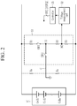
- FIG. 2 illustrates a detailed schematic view of an apparatus for estimating insulation resistance formed between each of positive and negative electrodes of a battery and a chassis ground according to an embodiment
- FIG. 3 illustrates a circuit diagram of an insulation resistance measurement circuit in a state in which first and second switches of FIG. 2 are turned on
- FIG. 4 illustrates a circuit diagram of an insulation resistance measurement circuit in a state in which a second switch of FIG. 2 is turned on
- FIG. 5 illustrates a circuit diagram of an insulation resistance measurement circuit in which a diagnosis resistor is added to an apparatus for estimating insulation resistance of FIG. 2 .
- the apparatus 50 for estimating the insulation resistance may include an insulation resistance measurement circuit 51, a voltage measurement part 52, and a controller 53.
- FIG. 1 illustrates that the apparatus 50 for estimating the insulation resistance is a separate configuration from the BMS 40, but the present invention is not limited thereto, and the apparatus 50 may be included in the BMS 40.
- the insulation resistance measurement circuit 51 includes a first resistor R1 having one end connected to one electrode of the battery 10, a first switch SW1 having one end connected to the other end of the first resistor R1, a second resistor R2 having one end connected to the other end of the first switch SW1, a third resistor R3 having one end connected to the other end of the second resistor R2 and the other end connected to the other electrode of the battery 10, and a second switch SW2 having one end connected to a first contact N1 between the first switch SW1 and the second resistor R2 and the other end connected to a chassis C ground.
- a value of the first resistor R1 may correspond to a sum of values of the second resistor R2 and the third resistor R3.
- a first insulation resistance Rp may be formed between the positive electrode of the battery 10 and the chassis C ground, and a second insulation resistance Rn may be formed between the negative electrode of the battery 10 and the chassis C ground.
- a value of an insulation resistance RL may be obtained by calculating a parallel (RpllRn) resistance value of the first insulation resistance Rp and the second insulation resistance Rn.
- the chassis C is a vehicle frame that forms a frame of a vehicle, and may mean a state in which a vehicle body is not mounted.
- the chassis C may be a form in which various constituent elements such as an engine, a transmission, a clutch, etc. are combined with a frame, which is a basic frame.
- the insulation resistance measurement circuit 51 is illustrated to be connected to the chassis C, but is not limited thereto, and may be combined with various devices.
- the voltage measurement part 52 measures a voltage of a second contact N2 between the second resistance R2 and the third resistance R3 according to an on or off state of the first switch SW1 and the second switch SW2 to transmit it to the controller 53.
- the voltage of the second contact N2 is a voltage Vp of the battery 10 applied to the third resistor R3 according to the on or off state of the first switch SW1 and the second switch SW2.
- the controller 53 controls switching of the first switch SW1 and the second switch SW2, and calculates the value of the insulation resistance RL based on a voltage measured at the second contact N2.
- the controller 53 may transmit the calculated value of the insulation resistance RL to the BMS 40.
- the controller 53 may derive the following Equation 1 based on a first voltage Va measured at the second contact N2 during an on period of the first switch SW1 and the second switch SW2.
- Va Rn11R 1 ⁇ Vp Pn11R 1 + Rp11R 1 ⁇ R 3 R 1
- the controller 53 may derive the following Equation 2 based on a second voltage Vb measured at the second contact N2 during an off period of the first switch SW1 and an on period of the second switch SW2.
- V b Rn11R 1 ⁇ Vp Pn11R 1 + Rp ⁇ R 3 R 1
- the controller 53 may derive the following Equation 3 by solving simultaneous equations of Equation 1 and Equation 2.
- Rp A ⁇ V b ⁇ V a A ⁇ V a ⁇ V b ⁇ 1 ⁇ R 1
- Rn A ⁇ V b ⁇ V a ⁇ A ⁇ V a ⁇ V b A ⁇ V a ⁇ A ⁇ A ⁇ V b ⁇ V a ⁇ R 1
- A R 3 ⁇ V p R 1
- the controller 53 may calculate the first insulation resistance Rp and the second insulation resistance Rn by Equation 3, and then may calculate a parallel (RpllRn) resistance value of the first insulation resistance Rp and the second insulation resistance Rn to obtain the value of the insulation resistance RL.
- the controller 53 may diagnose whether the insulation resistance measurement circuit 51 is normally operating by using the second switch SW2. Specifically, when the first switch SW1 is turned on by the controller 53 and when the second switch SW2 is turned off by the controller 53, the insulation resistance measurement circuit 51 is electrically separated from the first insulation resistance Rp, the second insulation resistance Rn, and the chassis C ground, while it is electrically connected to the positive and negative electrodes of the battery 10. In this case, the controller 53 may diagnose whether the insulation resistance measurement circuit 51 is normally operating based on the voltage measured at the second contact N2 and based on a resistance ratio of the first to third resistors R1, R2, and R3.
- the insulation resistance measurement circuit 51 may further include a diagnosis resistor RH connected between one electrode of the battery 10 and the other end of the second switch SW2.
- the controller 53 may diagnose whether the second switch SW2 is normally turned on or off by using the diagnosis resistor RH. Specifically, based on the voltage respectively measured at the second contact point N2 when the second switch SW2 is turned on and the second switch SW2 is turned off by the control unit 53 in the on state of the first switch SW1, and based on the values of the first to third resistors R1, R2, and R3 and the diagnostic resistor RH, whether the second switch SW2 is normally operated on/off may be diagnosed.
- FIG. 6 illustrates a detailed schematic view of an apparatus for estimating insulation resistance formed between an arbitrary electrode of a battery module and a chassis ground according to an embodiment
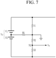
- FIG. 7 illustrates a circuit diagram of an insulation resistance measurement circuit in a state in which first and second switches of FIG. 6 are turned on
- FIG. 8 illustrates a circuit diagram of an insulation resistance measurement circuit in a state in which a first switch of FIG. 6 is turned off and a second switch thereof is turned on
- FIG. 9 illustrates a circuit diagram of an insulation resistance measurement circuit in which a diagnosis resistor is added to an apparatus for estimating insulation resistance of FIG. 6 .
- an apparatus 50 for estimating insulation resistance corresponds to the apparatus 50 for estimating the insulation resistance shown in FIG. 2 .
- Constituent elements respectively included in the apparatuses 50 for estimating the insulation resistance shown in FIG. 2 and FIG. 6 arrangements of the constituent elements, and functions thereof are the same.
- a description of the constituent elements of the apparatus 50 for estimating the insulation resistance illustrated in FIG. 6 will be replaced with the description of the constituent elements of the apparatus 50 for estimating the insulation resistance illustrated in FIG. 2 .
- the insulation resistance RL may be formed between an arbitrary electrode of the battery 10 and the chassis C ground.
- a sum of a voltage V1 between the positive electrode of battery 10 and a contact point connected to the insulation resistance RL and a voltage V2 between the contact point connected to the insulation resistance RL and the negative electrode of the battery 10 corresponds to a total voltage Vp of the battery 10.
- the controller 53 may derive the following Equation 4 based on the first voltage Va measured at the second contact N2 during the on period of the first switch SW1 and the second switch SW2.
- Va R 3 ⁇ R L 2 R L + R 1 ⁇ V p R 1 + V 2 R L
- the controller 53 may derive the following Equation 5 based on the second voltage Vb measured at the second contact N2 during the off period of the first switch SW1 and the on period of the second switch SW2.
- V 2 R L + R 1 ⁇ V b R 3
- the controller 53 may derive the following Equation 6 related to the insulation resistance RL by solving simultaneous equations of Equation 4 and Equation 5.
- Equation 6 V a ⁇ V b ⁇ R 1 V b ⁇ 2 V a + R 3 ⁇ V p R 1
- Rn) resistance value of the first insulation resistance Rp and the second insulation resistance Rn and the value of the insulation resistance RL obtained based on Equation 4 to Equation 6 are the same.
- the controller 53 may diagnose whether the insulation resistance measurement circuit 51 is normally operating by using the second switch SW2. Specifically, when the first switch SW1 is turned on by the controller 53 and when the second switch SW2 is turned off by the controller 53, the insulation resistance measurement circuit 51 is electrically separated from the first insulation resistance Rp, the second insulation resistance Rn, and the chassis C ground, while it is electrically connected to the positive and negative electrodes of the battery 10. In this case, the controller 53 may diagnose whether the insulation resistance measurement circuit 51 is normally operating based on the voltage measured at the second contact N2 and based on the resistance ratio of the first to third resistors R1, R2, and R3.
- the insulation resistance measurement circuit 51 may further include a diagnosis resistor RH connected between one electrode of the battery 10 and the other end of the second switch SW2.
- the controller 53 may diagnose whether the second switch SW2 is normally turned on or off by using the diagnosis resistor RH. Specifically, based on the voltage respectively measured at the second contact point N2 when the second switch SW2 is turned on and the second switch SW2 is turned off by the control unit 53 in the on state of the first switch SW1, and based on the values of the first to third resistors R1, R2, and R3 and the diagnostic resistor RH, whether the second switch SW2 is normally operated on/off may be diagnosed.
- the voltage measurement part 52 measures a voltage of a second contact N2 between the second resistance R2 and the third resistance R3 according to an on or off state of the first switch SW1 and the second switch SW2 to transmit it to the controller 53.
- the voltage of the second contact N2 is a voltage Vp of the battery 10 applied to the third resistor R3 according to the on or off state of the first switch SW1 and the second switch SW2.
- the controller 53 controls switching of the first switch SW1 and the second switch SW2, and calculates the value of the insulation resistance RL based on a voltage measured at the second contact N2.
- the controller 53 may transmit the calculated value of the insulation resistance RL to the BMS 40.
- the controller 53 may derive the following Equation 1 based on a first voltage Va measured at the second contact N2 during an on period of the first switch SW1 and the second switch SW2.
- Va Rn11R 1 ⁇ Vp Pn11R 1 + Rp11R 1 ⁇ R 3 R 1
- the controller 53 may derive the following Equation 2 based on a second voltage Vb measured at the second contact N2 during an off period of the first switch SW1 and an on period of the second switch SW2.
- Vb Rn11R 1 ⁇ Vp Pn11R 1 + Rp ⁇ R 3 R 1
- the controller 53 may derive the following Equation 3 by solving simultaneous equations of Equation 1 and Equation 2.
- Rp A ⁇ V b ⁇ V a A ⁇ V a ⁇ V b ⁇ 1 ⁇ R 1
- Rn A ⁇ V b ⁇ V a ⁇ A ⁇ V a ⁇ V b A ⁇ V a ⁇ A ⁇ A ⁇ V b ⁇ V a ⁇ R 1
- A R 3 ⁇ V p R 1
- the controller 53 may calculate the first insulation resistance Rp and the second insulation resistance Rn by Equation 3, and then may calculate a parallel (RpllRn) resistance value of the first insulation resistance Rp and the second insulation resistance Rn to obtain the value of the insulation resistance RL.
- the controller 53 may diagnose whether the insulation resistance measurement circuit 51 is normally operating by using the second switch SW2. Specifically, when the first switch SW1 is turned on by the controller 53 and when the second switch SW2 is turned off by the controller 53, the insulation resistance measurement circuit 51 is electrically separated from the first insulation resistance Rp, the second insulation resistance Rn, and the chassis C ground, while it is electrically connected to the positive and negative electrodes of the battery 10. In this case, the controller 53 may diagnose whether the insulation resistance measurement circuit 51 is normally operating based on the voltage measured at the second contact N2 and based on a estimating the insulation resistance shown in FIG. 2 and FIG. 6 , arrangements of the constituent elements, and functions thereof are the same. Hereinafter, a description of the constituent elements of the apparatus 50 for estimating the insulation resistance illustrated in FIG. 6 will be replaced with the description of the constituent elements of the apparatus 50 for estimating the insulation resistance illustrated in FIG. 2 .
- the insulation resistance RL may be formed between an arbitrary electrode of the battery 10 and the chassis C ground.
- a sum of a voltage V1 between the positive electrode of battery 10 and a contact point connected to the insulation resistance RL and a voltage V2 between the contact point connected to the insulation resistance RL and the negative electrode of the battery 10 corresponds to a total voltage Vp of the battery 10.
- the controller 53 may derive the following Equation 4 based on the first voltage Va measured at the second contact N2 during the on period of the first switch SW1 and the second switch SW2.
- Va R 3 ⁇ R L 2 R L + R 1 ⁇ V p R 1 + V 2 R L
- the controller 53 may derive the following Equation 5 based on the second voltage Vb measured at the second contact N2 during the off period of the first switch SW1 and the on period of the second switch SW2.
- V2 R L + R1 ⁇ V b R3
- the controller 53 may derive the following Equation 6 related to the insulation resistance RL by solving simultaneous equations of Equation 4 and Equation 5.
- Equation 6 V a ⁇ V b ⁇ R1 V b ⁇ 2 V a + R3 ⁇ V p R1
- Rn) resistance value of the first insulation resistance Rp and the second insulation resistance Rn and the value of the insulation resistance RL obtained based on Equation 4 to Equation 6 are the same.
- the controller 53 may diagnose whether the insulation resistance measurement circuit 51 is normally operating by using the second switch SW2. Specifically, when the first switch SW1 is turned on by the controller 53 and when the second switch SW2 is turned off by the controller 53, the insulation resistance measurement circuit 51 is electrically separated from the first insulation resistance Rp, the second insulation resistance Rn, and the chassis C ground, while it is electrically connected to the positive and negative electrodes of the battery 10. In this case, the controller 53 may diagnose whether the insulation resistance measurement circuit 51 is normally operating based on the voltage measured at the second contact N2 and based on the resistance ratio of the first to third resistors R1, R2, and R3.
- the insulation resistance measurement circuit 51 may further include a diagnosis resistor RH connected between one electrode
Landscapes
- Engineering & Computer Science (AREA)
- Physics & Mathematics (AREA)
- General Physics & Mathematics (AREA)
- Chemical & Material Sciences (AREA)
- Power Engineering (AREA)
- General Chemical & Material Sciences (AREA)
- Electrochemistry (AREA)
- Chemical Kinetics & Catalysis (AREA)
- Manufacturing & Machinery (AREA)
- Sustainable Energy (AREA)
- Sustainable Development (AREA)
- Life Sciences & Earth Sciences (AREA)
- Transportation (AREA)
- Mechanical Engineering (AREA)
- Combustion & Propulsion (AREA)
- Measurement Of Resistance Or Impedance (AREA)
- Secondary Cells (AREA)
- Testing Of Short-Circuits, Discontinuities, Leakage, Or Incorrect Line Connections (AREA)
Abstract
Description
- This application claims priority to and the benefit of
Korean Patent Application No. 10-2019-0147977 filed in the Korean Intellectual Property Office on 11/18/2019 - The present invention relates to an apparatus for estimating insulation resistance and a battery system using the same.
- In a situation in which high capacity is required as in an electric vehicle, an energy storage system, and an uninterruptible power supply, a plurality of battery cells of a secondary battery may be connected to be used as a battery module, or a plurality of battery modules may be connected to be used as a battery pack.
- In a case of using a battery at high voltage by connecting battery cells or modules, insulation resistance of a predetermined level or more should be maintained to prevent electric shock to a user and to prevent unnecessary discharge. For example, when a high-voltage battery is applied and used in a vehicle, the insulation resistance between positive and negative electrodes of a battery and a chassis of the vehicle should be measured, and the insulation resistance should be maintained at a predetermined level or more.
- Since a conventional apparatus for estimating insulation resistance has a complex configuration, when the apparatus for estimating the insulation resistance is implemented as a printed circuit board (PCB), a volume thereof is increased, and a calculation is complicated, causing error occurrence and a calculation error.
- The present invention provides an apparatus for estimating insulation resistance having a simple configuration of an insulation resistance estimation circuit, and a battery system using the same.
- The present invention provides an apparatus for estimating insulation resistance that may calculate insulation resistance formed between each of positive and negative electrodes of a battery and a chassis ground, and a battery system using the same.
- The present invention provides an apparatus for estimating insulation resistance that may calculate insulation resistance formed between an arbitrary electrode of a battery and a chassis ground, and a battery system using the same.
- An apparatus for estimating insulation resistance according to an embodiment of the present invention includes: an insulation resistance measurement circuit that includes a first resistor having a first end connected to a first electrode of a battery, a first switch having a first end connected to a second end of the first resistor, a second resistor having a first end connected to a second end of the first switch, a third resistor having a first end connected to a second end of the second resistor and a second end connected to a second electrode of the battery, and a second switch having a first end connected to a first contact point between the first switch and the second resistor and a second end connected to a chassis ground; a voltage sensor configured to measure a voltage of a second contact point between the second resistor and the third resistor; and a controller configured to: control respective states of the first switch and the second switch; and calculate the insulation resistance value based on (i) the voltage measured at the second contact point while the first switch and the second switch are in an ON state and (ii) the voltage measured at the second contact point during while the first switch is in an OFF state and the second switch is in the ON state.
- The controller may be configured to diagnose whether the insulation resistance measurement circuit operates normally based on the voltage measured at the second contact point and a resistance ratio of the first, second and third resistors while the first switch is in the ON state and the second switch is in an OFF state.
- The controller may be configured to electrically disconnect the insulation resistance measurement circuit by turning the first switch and the second switch to the OFF state.
- The insulation resistance measurement circuit may further include a diagnosis resistor connected between the first electrode of the battery and the second end of the second switch.
- The controller may be configured to diagnose normal operation of the second switch based on (i) the voltage measured at the second contact point when the second switch is switched between the OFF state and the ON state while the first switch is in the ON state, (ii) resistance values of the first, second and third resistors, and (iii) a resistance value of the diagnosis resistor.
- A battery system including an apparatus for estimating insulation resistance according to another embodiment of the present invention includes: a battery including a plurality of battery cells that are connected in series; and an insulation resistance measurement circuit that includes a first resistor having a first end connected to a first electrode of a battery, a first switch having a first end connected to a second end of the first resistor, a second resistor having a first end connected to a second end of the first switch, a third resistor having a first end connected to a second end of the second resistor and a second end connected to a second electrode of the battery, and a second switch having a first end connected to a first contact point between the first switch and the second resistor and a second end connected to a chassis ground, wherein the insulation resistance measurement circuit is configured to measure a voltage of a second contact between the second resistor and the third resistor, wherein the apparatus for estimating the insulation resistance is configured to calculate an insulation resistance value, based on (i) the voltage measured at the second contact point while the first switch and the second switch are in an ON state and (ii) the voltage measured at the second contact point while the first switch is in an OFF state and the second switch is in the ON state.
- The apparatus for estimating the insulation resistance may be configured to diagnose whether the apparatus for estimating the insulation resistance operates normally based on the voltage measured at the second contact point and a resistance ratio of the first, second and third resistors while the first switch is in the ON state and the second switch is in an OFF state.
- The apparatus for estimating the insulation resistance may be configured to electrically disconnect the apparatus for estimating the insulation resistance by turning the first switch and the second switch to the OFF state.
- The apparatus for estimating the insulation resistance may further include a diagnosis resistor connected between the first electrode of the battery and the second end of the second switch.
- The apparatus for estimating the insulation resistance may be configured to diagnose normal operation of the second switch based on (i) the voltagemeasured at the second contact point when the second switch is switched between the OFF state and the ON state while the first switch is in the ON state, (ii) resistance values of the first, second and third resistors, and (iii) a resistance value of the diagnosis resistor.
- The present invention provides an effect of simplifying a circuit for estimating insulation resistance to reduce a volume and reduce a cost when designing a PCB of an apparatus for estimating insulation resistance.
-
-
FIG. 1 illustrates a schematic view of a battery system according to an embodiment. -
FIG. 2 illustrates a detailed schematic view of an apparatus for estimating insulation resistance formed between each of positive and negative electrodes of a battery and a chassis ground according to an embodiment. -
FIG. 3 illustrates a circuit diagram of an insulation resistance measurement circuit in a state in which first and second switches ofFIG. 2 are turned on. -
FIG. 4 illustrates a circuit diagram of an insulation resistance measurement circuit in a state in which a second switch ofFIG. 2 is turned on. -
FIG. 5 illustrates a circuit diagram of an insulation resistance measurement circuit in which a diagnosis resistor is added to an apparatus for estimating insulation resistance ofFIG. 2 . -
FIG. 6 illustrates a detailed schematic view of an apparatus for estimating insulation resistance formed between an arbitrary electrode of a battery module and a chassis ground according to an embodiment. -
FIG. 7 illustrates a circuit diagram of an insulation resistance measurement circuit in a state in which first and second switches ofFIG. 6 are turned on. -
FIG. 8 illustrates a circuit diagram of an insulation resistance measurement circuit in a state in which a first switch ofFIG. 6 is turned off and a second switch thereof is turned on. -
FIG. 9 illustrates a circuit diagram of an insulation resistance measurement circuit in which a diagnosis resistor is added to an apparatus for estimating insulation resistance ofFIG. 6 . - All constituent elements that are in a current path in a battery system are insulated from a chassis ground. In this case, a resistance component between all the constituent elements that are in the current path in the battery system and the chassis ground is referred to as insulation resistance. In the following embodiment, an insulation resistance formed between each of a positive electrode and a negative electrode of a battery and a chassis ground is assumed and described, or an insulation resistance formed between an arbitrary electrode of a battery and a chassis ground is assumed and described. However, an insulation resistance that may be formed in a battery system to which the present invention is applied is not limited to the above example.
- Hereinafter, embodiments disclosed in the present specification will be described in detail with reference to the accompanying drawings, and in the present specification, the same or similar constituent elements will be denoted by the same or similar reference numerals, and a redundant description thereof will be omitted. The terms "module" and/or "unit, portion, or part" representing constituent element used in the following description are used only in order to make understanding of the specification easier, and thus, these terms do not have meanings or roles that distinguish them from each other by themselves. In addition, in describing exemplary embodiments of the present specification, when it is determined that a detailed description of the well-known art associated with the present invention may obscure the gist of the present invention, it will be omitted. Further, the accompanying drawings are provided only in order to allow embodiments disclosed in the present specification to be easily understood and are not to be interpreted as limiting the spirit disclosed in the present specification, and it is to be understood that the present invention includes all modifications, equivalents, and substitutions without departing from the scope and spirit of the present invention.
- Terms including ordinal numbers such as first, second, and the like will be used only to describe various constituent elements, and are not to be interpreted as limiting these constituent elements. The terms are only used to differentiate one constituent element from other constituent elements.
- It is to be understood that when one constituent element is referred to as being "connected" or "coupled" to another constituent element, it may be connected or coupled directly to the other constituent element or may be connected or coupled to the other constituent element with a further constituent element intervening therebetween. In contrast, it should be understood that, when it is described that an element is "directly coupled" or "directly connected" to another element, no element is present between the element and the other element.
- In the present application, it should be understood that the term "include", "comprise", "have", or "configure" indicates that a feature, a number, a step, an operation, a constituent element, a part, or a combination thereof described in the specification is present, but does not exclude a possibility of presence or addition of one or more other features, numbers, steps, operations, constituent elements, parts, or combinations, in advance.
-
FIG. 1 is a drawing for illustrating a battery system according to an embodiment. - Referring to
FIG. 1 , abattery system 1 includes abattery 10, arelay 20, acurrent sensor 30, a battery management system (BMS) 40, and anapparatus 50 for estimating insulation resistance. - The
battery 10 may supply necessary power by including a plurality of battery cells connected in series/in parallel. As shown inFIG. 1 , thebattery 10 includes a plurality of battery cells Cell1 to Celln connected in series, it is connected between two output terminals OUT1 and OUT2 of thebattery system 1, therelay 20 is connected between a positive electrode of thebattery 10 and the output terminal OUT1, and thecurrent sensor 30 is connected between a negative electrode of thebattery 10 and the output terminal OUT2. - The
relay 20 controls electrical connection between thebattery system 1 and an external device. When therelay 20 is turned on, thebattery system 1 and the external devices are electrically connected such that charging or discharging is performed, and whenrelay 20 is turned off, thebattery system 1 and the external devices are electrically separated. - The
current sensor 30 is serially connected to a current path between thebattery 10 and the external device. Thecurrent sensor 30 estimates a current flowing through thebattery 10, that is, a charging current and a discharging current, and transmits an estimated result to theBMS 40. - The
BMS 40 may monitor a voltage, a current, and a temperature of a cell of thebattery 10 in real time, uniformly maintain a voltage between the plurality of battery cells Cell1 to Celln, and prevent excessive charging/discharging to optimally manage a state thereof. For example, The BMS 40 may diagnose stability related to the insulation resistance by receiving an insulation resistance estimation result from theapparatus 50 for estimating the insulation resistance. When theBMS 40 determines that there is a problem with the stability of the insulation resistance, it may generate a notification message. - The
apparatus 50 for estimating the insulation resistance may measure insulation resistance formed between each of positive and negative electrodes of thebattery 10 and a chassis ground, or measure insulation resistance formed between an arbitrary electrode of thebattery 10 and the chassis ground. For example, since theapparatus 50 for estimating the insulation resistance is electrically connected to thebattery system 1 when the insulation resistance is measured, and is electrically separated from thebattery system 1 when the insulation resistance is not measured, it is possible to prevent unnecessary noise and leakage current from occurring. -
FIG. 2 illustrates a detailed schematic view of an apparatus for estimating insulation resistance formed between each of positive and negative electrodes of a battery and a chassis ground according to an embodiment,FIG. 3 illustrates a circuit diagram of an insulation resistance measurement circuit in a state in which first and second switches ofFIG. 2 are turned on,FIG. 4 illustrates a circuit diagram of an insulation resistance measurement circuit in a state in which a second switch ofFIG. 2 is turned on, andFIG. 5 illustrates a circuit diagram of an insulation resistance measurement circuit in which a diagnosis resistor is added to an apparatus for estimating insulation resistance ofFIG. 2 . - Referring to
FIG. 2 , theapparatus 50 for estimating the insulation resistance may include an insulationresistance measurement circuit 51, avoltage measurement part 52, and acontroller 53.FIG. 1 illustrates that theapparatus 50 for estimating the insulation resistance is a separate configuration from theBMS 40, but the present invention is not limited thereto, and theapparatus 50 may be included in theBMS 40. - The insulation
resistance measurement circuit 51 includes a first resistor R1 having one end connected to one electrode of thebattery 10, a first switch SW1 having one end connected to the other end of the first resistor R1, a second resistor R2 having one end connected to the other end of the first switch SW1, a third resistor R3 having one end connected to the other end of the second resistor R2 and the other end connected to the other electrode of thebattery 10, and a second switch SW2 having one end connected to a first contact N1 between the first switch SW1 and the second resistor R2 and the other end connected to a chassis C ground. A value of the first resistor R1 may correspond to a sum of values of the second resistor R2 and the third resistor R3. - A first insulation resistance Rp may be formed between the positive electrode of the
battery 10 and the chassis C ground, and a second insulation resistance Rn may be formed between the negative electrode of thebattery 10 and the chassis C ground. A value of an insulation resistance RL may be obtained by calculating a parallel (RpllRn) resistance value of the first insulation resistance Rp and the second insulation resistance Rn. - The chassis C is a vehicle frame that forms a frame of a vehicle, and may mean a state in which a vehicle body is not mounted. The chassis C may be a form in which various constituent elements such as an engine, a transmission, a clutch, etc. are combined with a frame, which is a basic frame. In
FIG. 2 , the insulationresistance measurement circuit 51 is illustrated to be connected to the chassis C, but is not limited thereto, and may be combined with various devices. - The
voltage measurement part 52 measures a voltage of a second contact N2 between the second resistance R2 and the third resistance R3 according to an on or off state of the first switch SW1 and the second switch SW2 to transmit it to thecontroller 53. The voltage of the second contact N2 is a voltage Vp of thebattery 10 applied to the third resistor R3 according to the on or off state of the first switch SW1 and the second switch SW2. - The
controller 53 controls switching of the first switch SW1 and the second switch SW2, and calculates the value of the insulation resistance RL based on a voltage measured at the second contact N2. Thecontroller 53 may transmit the calculated value of the insulation resistance RL to theBMS 40. - Referring to
FIG. 3 , thecontroller 53 may derive thefollowing Equation 1 based on a first voltage Va measured at the second contact N2 during an on period of the first switch SW1 and the second switch SW2.
- Referring to
FIG. 4 , thecontroller 53 may derive thefollowing Equation 2 based on a second voltage Vb measured at the second contact N2 during an off period of the first switch SW1 and an on period of the second switch SW2.
- The
controller 53 may derive the following Equation 3 by solving simultaneous equations ofEquation 1 andEquation 2.
- The
controller 53 may calculate the first insulation resistance Rp and the second insulation resistance Rn by Equation 3, and then may calculate a parallel (RpllRn) resistance value of the first insulation resistance Rp and the second insulation resistance Rn to obtain the value of the insulation resistance RL. - The
controller 53 may diagnose whether the insulationresistance measurement circuit 51 is normally operating by using the second switch SW2. Specifically, when the first switch SW1 is turned on by thecontroller 53 and when the second switch SW2 is turned off by thecontroller 53, the insulationresistance measurement circuit 51 is electrically separated from the first insulation resistance Rp, the second insulation resistance Rn, and the chassis C ground, while it is electrically connected to the positive and negative electrodes of thebattery 10. In this case, thecontroller 53 may diagnose whether the insulationresistance measurement circuit 51 is normally operating based on the voltage measured at the second contact N2 and based on a resistance ratio of the first to third resistors R1, R2, and R3. - Referring to
FIG. 5 , the insulationresistance measurement circuit 51 may further include a diagnosis resistor RH connected between one electrode of thebattery 10 and the other end of the second switch SW2. Thecontroller 53 may diagnose whether the second switch SW2 is normally turned on or off by using the diagnosis resistor RH. Specifically, based on the voltage respectively measured at the second contact point N2 when the second switch SW2 is turned on and the second switch SW2 is turned off by thecontrol unit 53 in the on state of the first switch SW1, and based on the values of the first to third resistors R1, R2, and R3 and the diagnostic resistor RH, whether the second switch SW2 is normally operated on/off may be diagnosed. -
FIG. 6 illustrates a detailed schematic view of an apparatus for estimating insulation resistance formed between an arbitrary electrode of a battery module and a chassis ground according to an embodiment,FIG. 7 illustrates a circuit diagram of an insulation resistance measurement circuit in a state in which first and second switches ofFIG. 6 are turned on,FIG. 8 illustrates a circuit diagram of an insulation resistance measurement circuit in a state in which a first switch ofFIG. 6 is turned off and a second switch thereof is turned on, andFIG. 9 illustrates a circuit diagram of an insulation resistance measurement circuit in which a diagnosis resistor is added to an apparatus for estimating insulation resistance ofFIG. 6 . - Referring to
FIG. 6 , anapparatus 50 for estimating insulation resistance corresponds to theapparatus 50 for estimating the insulation resistance shown inFIG. 2 . Constituent elements respectively included in theapparatuses 50 for estimating the insulation resistance shown inFIG. 2 andFIG. 6 , arrangements of the constituent elements, and functions thereof are the same. Hereinafter, a description of the constituent elements of theapparatus 50 for estimating the insulation resistance illustrated inFIG. 6 will be replaced with the description of the constituent elements of theapparatus 50 for estimating the insulation resistance illustrated inFIG. 2 . - The insulation resistance RL may be formed between an arbitrary electrode of the
battery 10 and the chassis C ground. A sum of a voltage V1 between the positive electrode ofbattery 10 and a contact point connected to the insulation resistance RL and a voltage V2 between the contact point connected to the insulation resistance RL and the negative electrode of thebattery 10 corresponds to a total voltage Vp of thebattery 10. - Referring to
FIG. 6 andFIG. 7 , thecontroller 53 may derive the following Equation 4 based on the first voltage Va measured at the second contact N2 during the on period of the first switch SW1 and the second switch SW2.
- Referring to
FIG. 6 andFIG. 8 , thecontroller 53 may derive the following Equation 5 based on the second voltage Vb measured at the second contact N2 during the off period of the first switch SW1 and the on period of the second switch SW2.
- The
controller 53 may derive the following Equation 6 related to the insulation resistance RL by solving simultaneous equations of Equation 4 and Equation 5.
- When the insulation resistance Rp and the second insulation resistance Rn based on
Equation 1 to Equation 3 are calculated, respectively, the value of the insulation resistance RL obtained by calculating the parallel (Rp || Rn) resistance value of the first insulation resistance Rp and the second insulation resistance Rn and the value of the insulation resistance RL obtained based on Equation 4 to Equation 6 are the same. - The
controller 53 may diagnose whether the insulationresistance measurement circuit 51 is normally operating by using the second switch SW2. Specifically, when the first switch SW1 is turned on by thecontroller 53 and when the second switch SW2 is turned off by thecontroller 53, the insulationresistance measurement circuit 51 is electrically separated from the first insulation resistance Rp, the second insulation resistance Rn, and the chassis C ground, while it is electrically connected to the positive and negative electrodes of thebattery 10. In this case, thecontroller 53 may diagnose whether the insulationresistance measurement circuit 51 is normally operating based on the voltage measured at the second contact N2 and based on the resistance ratio of the first to third resistors R1, R2, and R3. - Referring to
FIG. 9 , the insulationresistance measurement circuit 51 may further include a diagnosis resistor RH connected between one electrode of thebattery 10 and the other end of the second switch SW2. Thecontroller 53 may diagnose whether the second switch SW2 is normally turned on or off by using the diagnosis resistor RH. Specifically, based on the voltage respectively measured at the second contact point N2 when the second switch SW2 is turned on and the second switch SW2 is turned off by thecontrol unit 53 in the on state of the first switch SW1, and based on the values of the first to third resistors R1, R2, and R3 and the diagnostic resistor RH, whether the second switch SW2 is normally operated on/off may be diagnosed. - While this invention has been described in connection with what is presently considered to be practical exemplary embodiments, it is to be understood that the invention is not limited to the disclosed embodiments, but, on the contrary, is intended to cover various modifications and equivalent arrangements included within the spirit and scope of the appended claims.
-
- 1: battery system
- 10: battery
- 20: relay
- 30: current sensor
- 40: BMS
- 50: apparatus for estimating insulation resistance
- The
voltage measurement part 52 measures a voltage of a second contact N2 between the second resistance R2 and the third resistance R3 according to an on or off state of the first switch SW1 and the second switch SW2 to transmit it to thecontroller 53. The voltage of the second contact N2 is a voltage Vp of thebattery 10 applied to the third resistor R3 according to the on or off state of the first switch SW1 and the second switch SW2. - The
controller 53 controls switching of the first switch SW1 and the second switch SW2, and calculates the value of the insulation resistance RL based on a voltage measured at the second contact N2. Thecontroller 53 may transmit the calculated value of the insulation resistance RL to theBMS 40. - Referring to
FIG. 3 , thecontroller 53 may derive thefollowing Equation 1 based on a first voltage Va measured at the second contact N2 during an on period of the first switch SW1 and the second switch SW2.
- Referring to
FIG. 4 , thecontroller 53 may derive thefollowing Equation 2 based on a second voltage Vb measured at the second contact N2 during an off period of the first switch SW1 and an on period of the second switch SW2.
- The
controller 53 may derive the following Equation 3 by solving simultaneous equations ofEquation 1 andEquation 2.
- The
controller 53 may calculate the first insulation resistance Rp and the second insulation resistance Rn by Equation 3, and then may calculate a parallel (RpllRn) resistance value of the first insulation resistance Rp and the second insulation resistance Rn to obtain the value of the insulation resistance RL. - The
controller 53 may diagnose whether the insulationresistance measurement circuit 51 is normally operating by using the second switch SW2. Specifically, when the first switch SW1 is turned on by thecontroller 53 and when the second switch SW2 is turned off by thecontroller 53, the insulationresistance measurement circuit 51 is electrically separated from the first insulation resistance Rp, the second insulation resistance Rn, and the chassis C ground, while it is electrically connected to the positive and negative electrodes of thebattery 10. In this case, thecontroller 53 may diagnose whether the insulationresistance measurement circuit 51 is normally operating based on the voltage measured at the second contact N2 and based on a
estimating the insulation resistance shown inFIG. 2 andFIG. 6 , arrangements of the constituent elements, and functions thereof are the same. Hereinafter, a description of the constituent elements of theapparatus 50 for estimating the insulation resistance illustrated inFIG. 6 will be replaced with the description of the constituent elements of theapparatus 50 for estimating the insulation resistance illustrated inFIG. 2 . - The insulation resistance RL may be formed between an arbitrary electrode of the
battery 10 and the chassis C ground. A sum of a voltage V1 between the positive electrode ofbattery 10 and a contact point connected to the insulation resistance RL and a voltage V2 between the contact point connected to the insulation resistance RL and the negative electrode of thebattery 10 corresponds to a total voltage Vp of thebattery 10. - Referring to
FIG. 6 andFIG. 7 , thecontroller 53 may derive the following Equation 4 based on the first voltage Va measured at the second contact N2 during the on period of the first switch SW1 and the second switch SW2.
- Referring to
FIG. 6 andFIG. 8 , thecontroller 53 may derive the following Equation 5 based on the second voltage Vb measured at the second contact N2 during the off period of the first switch SW1 and the on period of the second switch SW2.
- The
controller 53 may derive the following Equation 6 related to the
insulation resistance RL by solving simultaneous equations of Equation 4 and Equation 5.
- When the insulation resistance Rp and the second insulation resistance Rn based on
Equation 1 to Equation 3 are calculated, respectively, the value of the insulation resistance RL obtained by calculating the parallel (Rp || Rn) resistance value of the first insulation resistance Rp and the second insulation resistance Rn and the value of the insulation resistance RL obtained based on Equation 4 to Equation 6 are the same. - The
controller 53 may diagnose whether the insulationresistance measurement circuit 51 is normally operating by using the second switch SW2. Specifically, when the first switch SW1 is turned on by thecontroller 53 and when the second switch SW2 is turned off by thecontroller 53, the insulationresistance measurement circuit 51 is electrically separated from the first insulation resistance Rp, the second insulation resistance Rn, and the chassis C ground, while it is electrically connected to the positive and negative electrodes of thebattery 10. In this case, thecontroller 53 may diagnose whether the insulationresistance measurement circuit 51 is normally operating based on the voltage measured at the second contact N2 and based on the resistance ratio of the first to third resistors R1, R2, and R3. - Referring to
FIG. 9 , the insulationresistance measurement circuit 51 may further include a diagnosis resistor RH connected between one electrode
Claims (10)
- An apparatus for estimating insulation resistance, comprising:an insulation resistance measurement circuit that includes a first resistor having a first end connected to a first electrode of a battery, a first switch having a first end connected to a second end of the first resistor, a second resistor having a first end connected to a second end of the first switch, a third resistor having a first end connected to a second end of the second resistor and a second end connected to a second electrode of the battery, and a second switch having a first end connected to a first contact point between the first switch and the second resistor and a second end connected to a chassis ground;a voltage sensor configured to measure a voltage of a second contact point between the second resistor and the third resistor; anda controller configured to:control respective states of the first switch and the second switch; andcalculate the insulation resistance value based on (i) the voltage measured at the second contact point while the first switch and the second switch are in an ON state and (ii) the voltage measured at the second contact point during while the first switch is in an OFF state and the second switch is in the ON state.
- The apparatus for estimating the insulation resistance of claim 1, wherein
the controller is configured to diagnose whether the insulation resistance measurement circuit operates normally based on the voltage measured at the second contact point and a resistance ratio of the first, second and third resistors while the first switch is in the ON state and the second switch is in an OFF state. - The apparatus for estimating the insulation resistance of claim 1, wherein
the controller is configured to electrically disconnect the insulation resistance measurement circuit by turning the first switch and the second switch to the OFF state. - The apparatus for estimating the insulation resistance of claim 1, wherein
the insulation resistance measurement circuit further includes a diagnosis resistor connected between the first electrode of the battery and the second end of the second switch. - The apparatus for estimating the insulation resistance of claim 4, wherein
the controller is configured to diagnose normal operation of the second switch based on (i) the voltage measured at the second contact point when the second switch is switched between the OFF state and the ON state while the first switch is in the ON state, (ii) resistance values of the first, second and third resistors, and (iii) a resistance value of the diagnosis resistor. - A battery system including an apparatus for estimating insulation resistance, comprising:a battery including a plurality of battery cells that are connected in series; andan insulation resistance measurement circuit that includes a first resistor having a first end connected to a first electrode of a battery, a first switch having a first end connected to a second end of the first resistor, a second resistor having a first end connected to a second end of the first switch, a third resistor having a first end connected to a second end of the second resistor and a second end connected to a second electrode of the battery, and a second switch having a first end connected to a first contact point between the first switch and the second resistor and a second end connected to a chassis ground, wherein the insulation resistance measurement circuit is configured to measure a voltage of a second contact between the second resistor and the third resistor,wherein the apparatus for estimating the insulation resistance is configured to calculate an insulation resistance value, based on (i) the voltage measured at the second contact point while the first switch and the second switch are in an ON state and (ii) the voltage measured at the second contact point while the first switch is in an OFF state and the second switch is in the ON state.
- The battery system of claim 6, wherein
the apparatus for estimating the insulation resistance is configured to diagnose whether the apparatus for estimating the insulation resistance operates normally based on the voltage measured at the second contact point and a resistance ratio of the first, second and third resistors while the first switch is in the ON state and the second switch is in an OFF state. - The battery system of claim 6, wherein
the apparatus for estimating the insulation resistance is configured to electrically disconnect the apparatus for estimating the insulation resistance by turning the first switch and the second switch to the OFF state. - The battery system of claim 6, wherein
the apparatus for estimating the insulation resistance further includes a diagnosis resistor connected between the first electrode of the battery and the second end of the second switch. - The battery system of claim 9, wherein
the apparatus for estimating the insulation resistance is configured to diagnose normal operation of the second switch based on (i) the voltagemeasured at the second contact point when the second switch is switched between the OFF state and the ON state while the first switch is in the ON state, (ii) resistance values of the first, second and third resistors, and (iii) a resistance value of the diagnosis resistor.
Applications Claiming Priority (2)
| Application Number | Priority Date | Filing Date | Title |
|---|---|---|---|
| KR1020190147977A KR102731446B1 (en) | 2019-11-18 | 2019-11-18 | Apparatus for estimating Insulation Resistance and Battery System using the same |
| PCT/KR2020/013068 WO2021101059A1 (en) | 2019-11-18 | 2020-09-25 | Apparatus for measuring insulation resistance and battery system using same |
Publications (3)
| Publication Number | Publication Date |
|---|---|
| EP3933415A1 true EP3933415A1 (en) | 2022-01-05 |
| EP3933415A4 EP3933415A4 (en) | 2022-06-01 |
| EP3933415B1 EP3933415B1 (en) | 2024-08-14 |
Family
ID=75981676
Family Applications (1)
| Application Number | Title | Priority Date | Filing Date |
|---|---|---|---|
| EP20889304.0A Active EP3933415B1 (en) | 2019-11-18 | 2020-09-25 | Apparatus for estimating insulation resistance and battery system using the same |
Country Status (8)
| Country | Link |
|---|---|
| US (1) | US11841389B2 (en) |
| EP (1) | EP3933415B1 (en) |
| JP (1) | JP7264578B2 (en) |
| KR (1) | KR102731446B1 (en) |
| CN (1) | CN113557435B (en) |
| ES (1) | ES2986968T3 (en) |
| HU (1) | HUE068307T2 (en) |
| WO (1) | WO2021101059A1 (en) |
Cited By (1)
| Publication number | Priority date | Publication date | Assignee | Title |
|---|---|---|---|---|
| TWI802331B (en) * | 2022-03-22 | 2023-05-11 | 新普科技股份有限公司 | An insulation resistance detecting equipment and detecting method thereof |
Families Citing this family (14)
| Publication number | Priority date | Publication date | Assignee | Title |
|---|---|---|---|---|
| DE102018221479A1 (en) * | 2018-12-12 | 2020-06-18 | Robert Bosch Gmbh | Circuit arrangement for fault detection in an unearthed high-voltage system |
| CN118418838B (en) * | 2021-09-23 | 2025-11-18 | 北京理工大学 | A high-voltage battery insulation monitoring system for electric vehicles |
| CN113777514B (en) * | 2021-09-24 | 2023-06-16 | 重庆电哥科技(集团)有限公司 | Insulation detection circuit, system and method of back-up energy storage system |
| KR102679033B1 (en) * | 2021-10-01 | 2024-06-26 | 재단법인 한국기계전기전자시험연구원 | Long term withstand voltage and insulation resistance measurement test system |
| DE102021127385B3 (en) * | 2021-10-21 | 2022-11-03 | Dr. Ing. H.C. F. Porsche Aktiengesellschaft | Method for plausibility checking of insulation monitoring of a high-voltage system of an electric vehicle while charging a traction battery of the electric vehicle |
| KR102920220B1 (en) * | 2021-11-12 | 2026-01-30 | 주식회사 엘지에너지솔루션 | Apparatus for measuring insulation resistance |
| KR102946713B1 (en) | 2021-11-22 | 2026-03-31 | 주식회사 엘지에너지솔루션 | Device for measuring insulation resistance and battery system comprising the same |
| CN114325102A (en) * | 2021-12-23 | 2022-04-12 | 珠海格力电器股份有限公司 | Insulation resistance detection circuit and insulation resistance detection method thereof, automobile |
| KR102945059B1 (en) * | 2022-01-06 | 2026-03-26 | 주식회사 엘지에너지솔루션 | Battery apparatus and battery management system for measuring insulation resistance |
| CN117991122A (en) * | 2022-10-31 | 2024-05-07 | 比亚迪股份有限公司 | Insulation monitoring circuit, battery energy storage system and insulation monitoring method |
| KR20240153794A (en) | 2023-04-17 | 2024-10-24 | 현대자동차주식회사 | System for diagnostic of a battery pack, and method thereof |
| KR20250035261A (en) * | 2023-09-05 | 2025-03-12 | 주식회사 엘지에너지솔루션 | Isolation diagnostic circuit and battery system comprising the same |
| CN117783672A (en) * | 2023-12-12 | 2024-03-29 | 江苏速豹动力科技有限公司 | Vehicle insulation testing devices and new energy vehicles |
| CN118518939B (en) * | 2024-07-19 | 2025-01-24 | 珠海科创储能科技有限公司 | Insulation resistance detection circuit, method and electronic device in battery cluster |
Family Cites Families (25)
| Publication number | Priority date | Publication date | Assignee | Title |
|---|---|---|---|---|
| JPH01165973A (en) * | 1987-12-23 | 1989-06-29 | Kawasaki Steel Corp | Measuring device of insulation resistance of direct-current circuit |
| JP2006220520A (en) | 2005-02-10 | 2006-08-24 | Honda Motor Co Ltd | Insulation resistance measuring apparatus and method for non-grounded DC power supply |
| JP2012173053A (en) * | 2011-02-18 | 2012-09-10 | Mitsubishi Heavy Ind Ltd | Electric leak detecting device and method for the same |
| WO2013018411A1 (en) * | 2011-07-29 | 2013-02-07 | 三洋電機株式会社 | Motor drive circuit, motor device, and moving vehicle |
| EP2570289B1 (en) | 2011-09-16 | 2018-08-15 | Samsung SDI Co., Ltd. | Device for determining the insulation resistance of a high-voltage battery system |
| KR101470553B1 (en) * | 2012-03-26 | 2014-12-10 | 주식회사 엘지화학 | Apparatus and method for measuring isolation resistance of battery |
| WO2013147493A1 (en) * | 2012-03-27 | 2013-10-03 | 주식회사 엘지화학 | Insulation resistance measurement device having malfuction self-diagnosis function, and method for self-diagnosing malfuction using same |
| US9046559B2 (en) | 2012-05-09 | 2015-06-02 | Curtis Instruments, Inc. | Isolation monitor |
| KR20130128597A (en) * | 2012-05-17 | 2013-11-27 | 현대모비스 주식회사 | Insulation resistance sensing circuit and battery management system including the same |
| JP2014020914A (en) | 2012-07-18 | 2014-02-03 | Keihin Corp | Leak detection device |
| KR101389362B1 (en) | 2012-09-27 | 2014-04-25 | 현대오트론 주식회사 | Apparatus and method for measuring insulation resistance |
| DE102013215731A1 (en) | 2013-08-09 | 2015-02-12 | Volkswagen Aktiengesellschaft | Method and device for measuring one or more insulation resistances in a motor vehicle |
| KR101512395B1 (en) | 2013-10-08 | 2015-04-16 | 현대오트론 주식회사 | Apparatus and method for measuring insulation resistance |
| KR101984326B1 (en) * | 2014-01-07 | 2019-09-03 | 에스케이이노베이션 주식회사 | Apparatus and method for measuring insulation resistance of battery |
| JP6433305B2 (en) | 2014-04-09 | 2018-12-05 | 矢崎総業株式会社 | Insulation detection device and insulation detection method for non-grounded power supply |
| KR101619328B1 (en) | 2014-11-17 | 2016-05-10 | 현대오트론 주식회사 | Apparatus for measuring isolation resistance and method thereof |
| US9772392B2 (en) | 2015-02-26 | 2017-09-26 | Lear Corporation | Apparatus and method for diagnosing hardware in an insulation resistance monitoring system for a vehicle |
| CN105277787B (en) * | 2015-09-30 | 2018-09-11 | 上海凌翼动力科技有限公司 | Electric automobile insulation Resistance Fault prediction technique and system |
| ITUB20159266A1 (en) | 2015-12-18 | 2017-06-18 | Magneti Marelli Spa | Electronic device, system and method for measurements of insulation resistance, with self-diagnosis 5 functions and diagnosis of loss of insulation of an electric apparatus energized with respect to ground. |
| CN206038771U (en) * | 2016-08-23 | 2017-03-22 | 深圳市国新动力科技有限公司 | Electric automobile insulation resistance detection circuitry |
| KR101887442B1 (en) | 2016-11-09 | 2018-08-10 | 현대오트론 주식회사 | Diagnosis apparatus of insulation resistance measurement circuit |
| EP3361271B1 (en) | 2017-02-08 | 2022-06-01 | Fico Triad, S.A. | Device and method for measuring isolation resistance of battery powered systems |
| KR102065822B1 (en) | 2017-06-27 | 2020-02-11 | 주식회사 엘지화학 | System and method for calculating insulation resistance |
| JP6698599B2 (en) | 2017-09-21 | 2020-05-27 | 矢崎総業株式会社 | Ground fault detector |
| CN108872812B (en) * | 2018-06-29 | 2021-01-01 | 深圳市国新动力科技有限公司 | Low-cost insulation leakage detection circuit and detection method |
-
2019
- 2019-11-18 KR KR1020190147977A patent/KR102731446B1/en active Active
-
2020
- 2020-09-25 ES ES20889304T patent/ES2986968T3/en active Active
- 2020-09-25 HU HUE20889304A patent/HUE068307T2/en unknown
- 2020-09-25 EP EP20889304.0A patent/EP3933415B1/en active Active
- 2020-09-25 CN CN202080020599.9A patent/CN113557435B/en active Active
- 2020-09-25 WO PCT/KR2020/013068 patent/WO2021101059A1/en not_active Ceased
- 2020-09-25 US US17/439,019 patent/US11841389B2/en active Active
- 2020-09-25 JP JP2021544341A patent/JP7264578B2/en active Active
Cited By (1)
| Publication number | Priority date | Publication date | Assignee | Title |
|---|---|---|---|---|
| TWI802331B (en) * | 2022-03-22 | 2023-05-11 | 新普科技股份有限公司 | An insulation resistance detecting equipment and detecting method thereof |
Also Published As
| Publication number | Publication date |
|---|---|
| CN113557435A (en) | 2021-10-26 |
| JP2022531527A (en) | 2022-07-07 |
| KR102731446B1 (en) | 2024-11-15 |
| WO2021101059A1 (en) | 2021-05-27 |
| ES2986968T3 (en) | 2024-11-13 |
| US11841389B2 (en) | 2023-12-12 |
| JP7264578B2 (en) | 2023-04-25 |
| KR20210060210A (en) | 2021-05-26 |
| US20220146561A1 (en) | 2022-05-12 |
| EP3933415B1 (en) | 2024-08-14 |
| CN113557435B (en) | 2024-04-05 |
| EP3933415A4 (en) | 2022-06-01 |
| HUE068307T2 (en) | 2024-12-28 |
Similar Documents
| Publication | Publication Date | Title |
|---|---|---|
| US11841389B2 (en) | Apparatus for estimating insulation resistance and battery system using the same | |
| EP3982140B1 (en) | Device for managing battery and method for managing battery | |
| JP6725201B2 (en) | Charge leveling device and power supply system | |
| EP1837944B1 (en) | Electric power supply control apparatus | |
| KR101497602B1 (en) | Balancing system for battery and Method for balancing of battery using the same | |
| JP5715694B2 (en) | Battery control device, battery system | |
| JP6382453B2 (en) | Battery monitoring device | |
| EP3998491B1 (en) | Apparatus and method for diagnosing insulation resistance measurement circuit | |
| EP3920308A1 (en) | Battery control device | |
| US20240066993A1 (en) | Battery Diagnosis Device, Battery Management System, Battery Pack, Electric Vehicle And Battery Diagnosis Method | |
| JP6706688B2 (en) | Battery control device | |
| EP3901640B1 (en) | DEVICE FOR MEASURING INSULATION RESISTANCE | |
| JP2009286292A (en) | Vehicular power supply device | |
| JPWO2013024541A1 (en) | Battery monitoring device and battery control device provided with the same | |
| CN108333522A (en) | Differential voltage measuring device | |
| EP3816639A1 (en) | Integrated circuit, battery monitoring device, and battery monitoring system | |
| KR20210051809A (en) | Method for estimating of battery's state of charge and Battery Management System | |
| EP4239350B1 (en) | Insulation resistance measurement device | |
| JP2023553024A5 (en) | ||
| JP6434245B2 (en) | Charging rate estimation device and power supply system | |
| GB2643966A (en) | Lithium ion battery pack and charging system | |
| EP4685502A1 (en) | Relay diagnosis circuit and battery device comprising same | |
| KR102818350B1 (en) | Battery module, battery management system and method | |
| KR20210007569A (en) | Apparatus for calculating error of current sensor | |
| JP2020193821A (en) | Voltage measurement circuit and battery pack |
Legal Events
| Date | Code | Title | Description |
|---|---|---|---|
| STAA | Information on the status of an ep patent application or granted ep patent |
Free format text: STATUS: THE INTERNATIONAL PUBLICATION HAS BEEN MADE |
|
| PUAI | Public reference made under article 153(3) epc to a published international application that has entered the european phase |
Free format text: ORIGINAL CODE: 0009012 |
|
| STAA | Information on the status of an ep patent application or granted ep patent |
Free format text: STATUS: REQUEST FOR EXAMINATION WAS MADE |
|
| PUAB | Information related to the publication of an a document modified or deleted |
Free format text: ORIGINAL CODE: 0009199EPPU |
|
| PUAI | Public reference made under article 153(3) epc to a published international application that has entered the european phase |
Free format text: ORIGINAL CODE: 0009012 |
|
| 17P | Request for examination filed |
Effective date: 20210910 |
|
| AK | Designated contracting states |
Kind code of ref document: A1 Designated state(s): AL AT BE BG CH CY CZ DE DK EE ES FI FR GB GR HR HU IE IS IT LI LT LU LV MC MK MT NL NO PL PT RO RS SE SI SK SM TR |
|
| RAP3 | Party data changed (applicant data changed or rights of an application transferred) |
Owner name: LG ENERGY SOLUTION, LTD. |
|
| A4 | Supplementary search report drawn up and despatched |
Effective date: 20220503 |
|
| RIC1 | Information provided on ipc code assigned before grant |
Ipc: B60L 3/00 20190101ALI20220426BHEP Ipc: G01R 31/00 20060101ALI20220426BHEP Ipc: G01R 31/382 20190101ALI20220426BHEP Ipc: G01R 27/08 20060101ALI20220426BHEP Ipc: G01R 27/02 20060101AFI20220426BHEP |
|
| DAV | Request for validation of the european patent (deleted) | ||
| DAX | Request for extension of the european patent (deleted) | ||
| GRAP | Despatch of communication of intention to grant a patent |
Free format text: ORIGINAL CODE: EPIDOSNIGR1 |
|
| STAA | Information on the status of an ep patent application or granted ep patent |
Free format text: STATUS: GRANT OF PATENT IS INTENDED |
|
| INTG | Intention to grant announced |
Effective date: 20240319 |
|
| GRAS | Grant fee paid |
Free format text: ORIGINAL CODE: EPIDOSNIGR3 |
|
| GRAA | (expected) grant |
Free format text: ORIGINAL CODE: 0009210 |
|
| STAA | Information on the status of an ep patent application or granted ep patent |
Free format text: STATUS: THE PATENT HAS BEEN GRANTED |
|
| P01 | Opt-out of the competence of the unified patent court (upc) registered |
Free format text: CASE NUMBER: APP_39706/2024 Effective date: 20240703 |
|
| AK | Designated contracting states |
Kind code of ref document: B1 Designated state(s): AL AT BE BG CH CY CZ DE DK EE ES FI FR GB GR HR HU IE IS IT LI LT LU LV MC MK MT NL NO PL PT RO RS SE SI SK SM TR |
|
| REG | Reference to a national code |
Ref country code: GB Ref legal event code: FG4D |
|
| REG | Reference to a national code |
Ref country code: CH Ref legal event code: EP |
|
| REG | Reference to a national code |
Ref country code: DE Ref legal event code: R096 Ref document number: 602020035965 Country of ref document: DE |
|
| REG | Reference to a national code |
Ref country code: IE Ref legal event code: FG4D |
|
| REG | Reference to a national code |
Ref country code: ES Ref legal event code: FG2A Ref document number: 2986968 Country of ref document: ES Kind code of ref document: T3 Effective date: 20241113 |
|
| REG | Reference to a national code |
Ref country code: LT Ref legal event code: MG9D |
|
| REG | Reference to a national code |
Ref country code: NL Ref legal event code: MP Effective date: 20240814 |
|
| REG | Reference to a national code |
Ref country code: HU Ref legal event code: AG4A Ref document number: E068307 Country of ref document: HU |
|
| PG25 | Lapsed in a contracting state [announced via postgrant information from national office to epo] |
Ref country code: NO Free format text: LAPSE BECAUSE OF FAILURE TO SUBMIT A TRANSLATION OF THE DESCRIPTION OR TO PAY THE FEE WITHIN THE PRESCRIBED TIME-LIMIT Effective date: 20241114 |
|
| REG | Reference to a national code |
Ref country code: AT Ref legal event code: MK05 Ref document number: 1713762 Country of ref document: AT Kind code of ref document: T Effective date: 20240814 |
|
| PG25 | Lapsed in a contracting state [announced via postgrant information from national office to epo] |
Ref country code: FI Free format text: LAPSE BECAUSE OF FAILURE TO SUBMIT A TRANSLATION OF THE DESCRIPTION OR TO PAY THE FEE WITHIN THE PRESCRIBED TIME-LIMIT Effective date: 20240814 Ref country code: NL Free format text: LAPSE BECAUSE OF FAILURE TO SUBMIT A TRANSLATION OF THE DESCRIPTION OR TO PAY THE FEE WITHIN THE PRESCRIBED TIME-LIMIT Effective date: 20240814 Ref country code: PT Free format text: LAPSE BECAUSE OF FAILURE TO SUBMIT A TRANSLATION OF THE DESCRIPTION OR TO PAY THE FEE WITHIN THE PRESCRIBED TIME-LIMIT Effective date: 20241216 Ref country code: PL Free format text: LAPSE BECAUSE OF FAILURE TO SUBMIT A TRANSLATION OF THE DESCRIPTION OR TO PAY THE FEE WITHIN THE PRESCRIBED TIME-LIMIT Effective date: 20240814 Ref country code: GR Free format text: LAPSE BECAUSE OF FAILURE TO SUBMIT A TRANSLATION OF THE DESCRIPTION OR TO PAY THE FEE WITHIN THE PRESCRIBED TIME-LIMIT Effective date: 20241115 |
|
| PG25 | Lapsed in a contracting state [announced via postgrant information from national office to epo] |
Ref country code: BG Free format text: LAPSE BECAUSE OF FAILURE TO SUBMIT A TRANSLATION OF THE DESCRIPTION OR TO PAY THE FEE WITHIN THE PRESCRIBED TIME-LIMIT Effective date: 20240814 |
|
| PG25 | Lapsed in a contracting state [announced via postgrant information from national office to epo] |
Ref country code: LV Free format text: LAPSE BECAUSE OF FAILURE TO SUBMIT A TRANSLATION OF THE DESCRIPTION OR TO PAY THE FEE WITHIN THE PRESCRIBED TIME-LIMIT Effective date: 20240814 |
|
| PG25 | Lapsed in a contracting state [announced via postgrant information from national office to epo] |
Ref country code: AT Free format text: LAPSE BECAUSE OF FAILURE TO SUBMIT A TRANSLATION OF THE DESCRIPTION OR TO PAY THE FEE WITHIN THE PRESCRIBED TIME-LIMIT Effective date: 20240814 Ref country code: IS Free format text: LAPSE BECAUSE OF FAILURE TO SUBMIT A TRANSLATION OF THE DESCRIPTION OR TO PAY THE FEE WITHIN THE PRESCRIBED TIME-LIMIT Effective date: 20241214 |
|
| PG25 | Lapsed in a contracting state [announced via postgrant information from national office to epo] |
Ref country code: HR Free format text: LAPSE BECAUSE OF FAILURE TO SUBMIT A TRANSLATION OF THE DESCRIPTION OR TO PAY THE FEE WITHIN THE PRESCRIBED TIME-LIMIT Effective date: 20240814 |
|
| PG25 | Lapsed in a contracting state [announced via postgrant information from national office to epo] |
Ref country code: RS Free format text: LAPSE BECAUSE OF FAILURE TO SUBMIT A TRANSLATION OF THE DESCRIPTION OR TO PAY THE FEE WITHIN THE PRESCRIBED TIME-LIMIT Effective date: 20241114 |
|
| PG25 | Lapsed in a contracting state [announced via postgrant information from national office to epo] |
Ref country code: RS Free format text: LAPSE BECAUSE OF FAILURE TO SUBMIT A TRANSLATION OF THE DESCRIPTION OR TO PAY THE FEE WITHIN THE PRESCRIBED TIME-LIMIT Effective date: 20241114 Ref country code: PT Free format text: LAPSE BECAUSE OF FAILURE TO SUBMIT A TRANSLATION OF THE DESCRIPTION OR TO PAY THE FEE WITHIN THE PRESCRIBED TIME-LIMIT Effective date: 20241216 Ref country code: PL Free format text: LAPSE BECAUSE OF FAILURE TO SUBMIT A TRANSLATION OF THE DESCRIPTION OR TO PAY THE FEE WITHIN THE PRESCRIBED TIME-LIMIT Effective date: 20240814 Ref country code: NO Free format text: LAPSE BECAUSE OF FAILURE TO SUBMIT A TRANSLATION OF THE DESCRIPTION OR TO PAY THE FEE WITHIN THE PRESCRIBED TIME-LIMIT Effective date: 20241114 Ref country code: NL Free format text: LAPSE BECAUSE OF FAILURE TO SUBMIT A TRANSLATION OF THE DESCRIPTION OR TO PAY THE FEE WITHIN THE PRESCRIBED TIME-LIMIT Effective date: 20240814 Ref country code: LV Free format text: LAPSE BECAUSE OF FAILURE TO SUBMIT A TRANSLATION OF THE DESCRIPTION OR TO PAY THE FEE WITHIN THE PRESCRIBED TIME-LIMIT Effective date: 20240814 Ref country code: IS Free format text: LAPSE BECAUSE OF FAILURE TO SUBMIT A TRANSLATION OF THE DESCRIPTION OR TO PAY THE FEE WITHIN THE PRESCRIBED TIME-LIMIT Effective date: 20241214 Ref country code: HR Free format text: LAPSE BECAUSE OF FAILURE TO SUBMIT A TRANSLATION OF THE DESCRIPTION OR TO PAY THE FEE WITHIN THE PRESCRIBED TIME-LIMIT Effective date: 20240814 Ref country code: GR Free format text: LAPSE BECAUSE OF FAILURE TO SUBMIT A TRANSLATION OF THE DESCRIPTION OR TO PAY THE FEE WITHIN THE PRESCRIBED TIME-LIMIT Effective date: 20241115 Ref country code: FI Free format text: LAPSE BECAUSE OF FAILURE TO SUBMIT A TRANSLATION OF THE DESCRIPTION OR TO PAY THE FEE WITHIN THE PRESCRIBED TIME-LIMIT Effective date: 20240814 Ref country code: BG Free format text: LAPSE BECAUSE OF FAILURE TO SUBMIT A TRANSLATION OF THE DESCRIPTION OR TO PAY THE FEE WITHIN THE PRESCRIBED TIME-LIMIT Effective date: 20240814 Ref country code: AT Free format text: LAPSE BECAUSE OF FAILURE TO SUBMIT A TRANSLATION OF THE DESCRIPTION OR TO PAY THE FEE WITHIN THE PRESCRIBED TIME-LIMIT Effective date: 20240814 |
|
| PG25 | Lapsed in a contracting state [announced via postgrant information from national office to epo] |
Ref country code: RO Free format text: LAPSE BECAUSE OF FAILURE TO SUBMIT A TRANSLATION OF THE DESCRIPTION OR TO PAY THE FEE WITHIN THE PRESCRIBED TIME-LIMIT Effective date: 20240814 Ref country code: SM Free format text: LAPSE BECAUSE OF FAILURE TO SUBMIT A TRANSLATION OF THE DESCRIPTION OR TO PAY THE FEE WITHIN THE PRESCRIBED TIME-LIMIT Effective date: 20240814 Ref country code: DK Free format text: LAPSE BECAUSE OF FAILURE TO SUBMIT A TRANSLATION OF THE DESCRIPTION OR TO PAY THE FEE WITHIN THE PRESCRIBED TIME-LIMIT Effective date: 20240814 |
|
| PG25 | Lapsed in a contracting state [announced via postgrant information from national office to epo] |
Ref country code: EE Free format text: LAPSE BECAUSE OF FAILURE TO SUBMIT A TRANSLATION OF THE DESCRIPTION OR TO PAY THE FEE WITHIN THE PRESCRIBED TIME-LIMIT Effective date: 20240814 |
|
| PG25 | Lapsed in a contracting state [announced via postgrant information from national office to epo] |
Ref country code: CZ Free format text: LAPSE BECAUSE OF FAILURE TO SUBMIT A TRANSLATION OF THE DESCRIPTION OR TO PAY THE FEE WITHIN THE PRESCRIBED TIME-LIMIT Effective date: 20240814 |
|
| PG25 | Lapsed in a contracting state [announced via postgrant information from national office to epo] |
Ref country code: SK Free format text: LAPSE BECAUSE OF FAILURE TO SUBMIT A TRANSLATION OF THE DESCRIPTION OR TO PAY THE FEE WITHIN THE PRESCRIBED TIME-LIMIT Effective date: 20240814 Ref country code: IT Free format text: LAPSE BECAUSE OF FAILURE TO SUBMIT A TRANSLATION OF THE DESCRIPTION OR TO PAY THE FEE WITHIN THE PRESCRIBED TIME-LIMIT Effective date: 20240814 |
|
| REG | Reference to a national code |
Ref country code: CH Ref legal event code: PL |
|
| REG | Reference to a national code |
Ref country code: DE Ref legal event code: R097 Ref document number: 602020035965 Country of ref document: DE |
|
| PG25 | Lapsed in a contracting state [announced via postgrant information from national office to epo] |
Ref country code: LU Free format text: LAPSE BECAUSE OF NON-PAYMENT OF DUE FEES Effective date: 20240925 |
|
| PLBE | No opposition filed within time limit |
Free format text: ORIGINAL CODE: 0009261 |
|
| STAA | Information on the status of an ep patent application or granted ep patent |
Free format text: STATUS: NO OPPOSITION FILED WITHIN TIME LIMIT |
|
| PG25 | Lapsed in a contracting state [announced via postgrant information from national office to epo] |
Ref country code: MC Free format text: LAPSE BECAUSE OF FAILURE TO SUBMIT A TRANSLATION OF THE DESCRIPTION OR TO PAY THE FEE WITHIN THE PRESCRIBED TIME-LIMIT Effective date: 20240814 |
|
| 26N | No opposition filed |
Effective date: 20250515 |
|
| PG25 | Lapsed in a contracting state [announced via postgrant information from national office to epo] |
Ref country code: CH Free format text: LAPSE BECAUSE OF NON-PAYMENT OF DUE FEES Effective date: 20240930 |
|
| PG25 | Lapsed in a contracting state [announced via postgrant information from national office to epo] |
Ref country code: IE Free format text: LAPSE BECAUSE OF NON-PAYMENT OF DUE FEES Effective date: 20240925 |
|
| PG25 | Lapsed in a contracting state [announced via postgrant information from national office to epo] |
Ref country code: SE Free format text: LAPSE BECAUSE OF FAILURE TO SUBMIT A TRANSLATION OF THE DESCRIPTION OR TO PAY THE FEE WITHIN THE PRESCRIBED TIME-LIMIT Effective date: 20240814 |
|
| PGFP | Annual fee paid to national office [announced via postgrant information from national office to epo] |
Ref country code: DE Payment date: 20250820 Year of fee payment: 6 |
|
| PGFP | Annual fee paid to national office [announced via postgrant information from national office to epo] |
Ref country code: HU Payment date: 20250929 Year of fee payment: 6 Ref country code: GB Payment date: 20250820 Year of fee payment: 6 Ref country code: BE Payment date: 20250820 Year of fee payment: 6 |
|
| PGFP | Annual fee paid to national office [announced via postgrant information from national office to epo] |
Ref country code: FR Payment date: 20250821 Year of fee payment: 6 |
|
| PG25 | Lapsed in a contracting state [announced via postgrant information from national office to epo] |
Ref country code: CY Free format text: LAPSE BECAUSE OF FAILURE TO SUBMIT A TRANSLATION OF THE DESCRIPTION OR TO PAY THE FEE WITHIN THE PRESCRIBED TIME-LIMIT; INVALID AB INITIO Effective date: 20200925 |
|
| PGFP | Annual fee paid to national office [announced via postgrant information from national office to epo] |
Ref country code: ES Payment date: 20251007 Year of fee payment: 6 |