EP3933361A1 - Arrangement and method for measuring temperature of cable connection terminal of electric drive - Google Patents
Arrangement and method for measuring temperature of cable connection terminal of electric drive Download PDFInfo
- Publication number
- EP3933361A1 EP3933361A1 EP20182836.5A EP20182836A EP3933361A1 EP 3933361 A1 EP3933361 A1 EP 3933361A1 EP 20182836 A EP20182836 A EP 20182836A EP 3933361 A1 EP3933361 A1 EP 3933361A1
- Authority
- EP
- European Patent Office
- Prior art keywords
- connection terminal
- cable connection
- temperature
- measuring
- electric drive
- Prior art date
- Legal status (The legal status is an assumption and is not a legal conclusion. Google has not performed a legal analysis and makes no representation as to the accuracy of the status listed.)
- Withdrawn
Links
- 238000000034 method Methods 0.000 title claims abstract description 15
- 238000012544 monitoring process Methods 0.000 claims description 28
- 230000008878 coupling Effects 0.000 claims description 9
- 238000010168 coupling process Methods 0.000 claims description 9
- 238000005859 coupling reaction Methods 0.000 claims description 9
- 230000001939 inductive effect Effects 0.000 claims description 4
- 238000012546 transfer Methods 0.000 claims description 4
- 238000004891 communication Methods 0.000 description 7
- 238000005516 engineering process Methods 0.000 description 7
- 238000004590 computer program Methods 0.000 description 6
- 230000015654 memory Effects 0.000 description 5
- 238000010586 diagram Methods 0.000 description 4
- 239000004020 conductor Substances 0.000 description 3
- 238000012545 processing Methods 0.000 description 3
- 238000004364 calculation method Methods 0.000 description 2
- 238000005259 measurement Methods 0.000 description 2
- 239000004065 semiconductor Substances 0.000 description 2
- 238000003860 storage Methods 0.000 description 2
- XUIMIQQOPSSXEZ-UHFFFAOYSA-N Silicon Chemical compound [Si] XUIMIQQOPSSXEZ-UHFFFAOYSA-N 0.000 description 1
- 238000004458 analytical method Methods 0.000 description 1
- 230000008901 benefit Effects 0.000 description 1
- 230000001413 cellular effect Effects 0.000 description 1
- 238000013523 data management Methods 0.000 description 1
- 230000002950 deficient Effects 0.000 description 1
- 230000001419 dependent effect Effects 0.000 description 1
- 238000013461 design Methods 0.000 description 1
- 238000005265 energy consumption Methods 0.000 description 1
- 230000005669 field effect Effects 0.000 description 1
- 230000006870 function Effects 0.000 description 1
- 230000014509 gene expression Effects 0.000 description 1
- 230000002452 interceptive effect Effects 0.000 description 1
- 238000010801 machine learning Methods 0.000 description 1
- 238000012423 maintenance Methods 0.000 description 1
- 238000007726 management method Methods 0.000 description 1
- 238000004519 manufacturing process Methods 0.000 description 1
- 230000007246 mechanism Effects 0.000 description 1
- 239000007769 metal material Substances 0.000 description 1
- 230000006855 networking Effects 0.000 description 1
- 230000003287 optical effect Effects 0.000 description 1
- 238000005457 optimization Methods 0.000 description 1
- 230000008569 process Effects 0.000 description 1
- 229910052710 silicon Inorganic materials 0.000 description 1
- 239000010703 silicon Substances 0.000 description 1
- 230000003936 working memory Effects 0.000 description 1
Images



Classifications
-
- G—PHYSICS
- G01—MEASURING; TESTING
- G01K—MEASURING TEMPERATURE; MEASURING QUANTITY OF HEAT; THERMALLY-SENSITIVE ELEMENTS NOT OTHERWISE PROVIDED FOR
- G01K1/00—Details of thermometers not specially adapted for particular types of thermometer
- G01K1/14—Supports; Fastening devices; Arrangements for mounting thermometers in particular locations
- G01K1/143—Supports; Fastening devices; Arrangements for mounting thermometers in particular locations for measuring surface temperatures
-
- G—PHYSICS
- G01—MEASURING; TESTING
- G01K—MEASURING TEMPERATURE; MEASURING QUANTITY OF HEAT; THERMALLY-SENSITIVE ELEMENTS NOT OTHERWISE PROVIDED FOR
- G01K1/00—Details of thermometers not specially adapted for particular types of thermometer
- G01K1/02—Means for indicating or recording specially adapted for thermometers
- G01K1/024—Means for indicating or recording specially adapted for thermometers for remote indication
-
- G—PHYSICS
- G01—MEASURING; TESTING
- G01K—MEASURING TEMPERATURE; MEASURING QUANTITY OF HEAT; THERMALLY-SENSITIVE ELEMENTS NOT OTHERWISE PROVIDED FOR
- G01K1/00—Details of thermometers not specially adapted for particular types of thermometer
- G01K1/16—Special arrangements for conducting heat from the object to the sensitive element
Definitions
- the present invention relates to an arrangement and a method for measuring a temperature of a cable connection terminal of an electric drive.
- An electric drive generally refers to an electronic apparatus, which may be used to regulate the performance of an electric motor or another kind of load, for example.
- An electric drive may control the power, frequency and/or current supplied to the load, for instance.
- An electric drive and e.g. an electric motor controlled by the electric drive may form an electric drive system.
- An electric drive may comprise one or more electric power converter units or modules, such as rectifiers, inverters or frequency converters, for example.
- the electric drive may comprise cable connection terminals for connecting various input and/or output cables such as input power cables supplying power to the electric drive and output power cables supplying power from the electric drive to the load, such as a motor, for example.
- condition monitoring of the cable connections to the cable connection terminals of the electric drive may be done by measuring the temperatures of the cable connection terminals. This may be performed by using e.g. an infrared thermometer which enables to measure the temperature without touching the cable connection terminal possibly under tension.
- a problem related to the above solution is that the cable connection terminals of the electric drive may be located inside the housing of the electric drive possibly behind other components and/or the electric drive may be located in a difficult to reach location. Then, in order to measure the temperature e.g. with an infrared thermometer, which requires a physical view to the measured object, the measuring could be complicated and time consuming.
- An object of the present invention is thus to provide a method and an apparatus for implementing the method so as to overcome the above problems or at least to alleviate them.
- the objects of the invention are achieved by a measuring arrangement, and a method, which are characterized by what is stated in the independent claims.
- the preferred embodiments of the invention are disclosed in the dependent claims.
- the invention is based on the idea of thermally connecting a temperature sensor to a cable connection terminal of the electric drive, measuring the temperature of the cable connection terminal by the temperature sensor connected to the cable connection terminal, and transmitting the measured temperature.
- An advantage of the solution of the invention is that it enables the monitoring of the temperature of the cable connection terminal to be performed remotely.
- a measuring arrangement for measuring a temperature of a cable connection terminal of an electric drive comprises measuring means configured to measure the temperature of the cable connection terminal, the measuring means comprising at least one temperature sensor configured to be thermally connected to the cable connection terminal of the electric drive, and transmitting means configured to transmit the measured temperature from the measuring arrangement.
- a method for measuring a temperature of a cable connection terminal of an electric drive comprises thermally connecting a temperature sensor of a measuring arrangement to the cable connection terminal of the electric drive, measuring the temperature of the cable connection terminal by the temperature sensor of the measuring arrangement thermally connected to the cable connection terminal, and transmitting the measured temperature from the measuring arrangement to a temperature monitoring entity.
- Term 'electric drive' herein generally refers to an electronic apparatus, which may be used to regulate the performance of an electric motor or another load.
- An electric drive may control the power, frequency and/or current supplied to the motor, for instance.
- An electric drive and an electric motor controlled by the electric drive may form an electric drive system.
- An electric drive may comprise one or more electric power converter units or modules, such as rectifiers, inverters or frequency converters, for example.
- 'inverter' generally refers to an electronic device or circuitry that is able to convert direct current to alternating current.
- inverter is a semiconductor bridge implemented by means of controllable semiconductor switches, such as IGBTs (Insulated-Gate Bipolar Transistor) or FETs (Field-Effect Transistor), which are controlled according to a modulation or control scheme used.
- IGBTs Insulated-Gate Bipolar Transistor
- FETs Field-Effect Transistor
- FIGS 1 and 2 show an example of a measuring arrangement 100 according to an embodiment.
- the exemplary measuring arrangement 100 is connected to a cable connection terminal 200 of an electric drive.
- the exemplary cable connection terminal 200 comprises an electrical connecting part 210, such as a busbar, or a part thereof, or a similar electric conductor structure, and suitable fastening means comprising e.g. one or more bolts 220 and nuts 221 for clamping or fastening a cable 300 to the cable connection terminal 200.
- the structure of the cable connection terminal 200 may vary from the example shown and may depend e.g. on the voltage level and/or current level of the electrical connection in question.
- the cable connection terminal may be an input power cable connection terminal or an output power cable connection terminal of the electric drive, for example.
- the cable 300 in the illustrated examples is provided with a cable shoe (a cable lug) 310 to assist the connection of the cable 300 end to the cable connection terminal 200.
- a cable shoe a cable lug
- the cable 300 end could be directly connected to the cable connection terminal 200.
- the measuring arrangement 100 comprises a connection part 110 and a measuring unit 120 housing other elements of the exemplary measuring arrangement 100.
- connection parts 110 connected in parallel and/or in series with each other, for connecting the measuring arrangement 100 to the cable connection terminal 200.
- the measuring arrangement 100 comprises thermal connection means configured to thermally indirectly connect the at least one temperature sensor to the cable connection terminal of the electric drive via the thermal connection means.
- the at least one connection part 110 may function as such thermal connection means and provide at least a thermal connection between the cable connection terminal 200 and the measuring unit 120.
- the at least one connection part 110 may be made of thermally conducting material, such as metal material.
- the exemplary at least one connection part 110 may also physically fasten the measuring arrangement 100 to the cable connection terminal 200 such that no further fastening of the measuring arrangement 100 is needed.
- the measuring arrangement 100, or some part or parts thereof, could be physically fastened to another part within the electric drive such that mainly a thermal connection between the measuring arrangement 100 and the cable connection terminal 200 is provided, for example.
- Such one or more connection parts 110 providing the thermal connection and/or physical fastening of the measuring arrangement 100 is preferably suitably shaped such that it can be connected to the cable connection terminal 200 without interfering the functioning of the cable connection terminal 200.
- the at least one connection part 110 comprises, at least partly, a sheet-like structure, which can be sandwiched between the cable connection terminal 200 and the end of the cable 300 connected to the connection terminal 200.
- the connection part 110 may accurately convey the actual temperature in the cable connection terminal 200 to the measuring unit 120.
- the thickness of such a sheet-like structure can be suitably selected such that it is thin enough to fit to the cable connection terminal 200 but at the same time thick enough to provide adequate physical fastening of the measuring arrangement 100 to the cable connection terminal 200, for example.
- the sheet-like structure of the connection part 110 may also comprise one or more holes for possible fastening bolts 220 or screws, for instance, as also shown in the example of Figures 1 and 2 to further facilitate the fastening of the measuring arrangement 100 to the cable connection terminal 200.
- the measuring arrangement 100 comprises measuring means configured to measure the temperature of the cable connection terminal 200 of the electric drive.
- Such measuring means may comprise at least one temperature sensor 101 configured to be thermally connected to the cable connection terminal 200 of the electric drive.
- the at least one temperature sensor 101 may be housed within the exemplary measuring unit 120 as shown in the example.
- the at least one temperature sensor 101 may be configured to be thermally directly connected to the cable connection terminal 200 of the electric drive.
- the at least one temperature sensor 101 could be directly connected to the cable connection terminal 200 hence providing a direct thermal connection.
- the at least one temperature sensor 101 may be configured to be thermally indirectly connected to the cable connection terminal 200 of the electric drive.
- Such indirect thermal connection may be provided via one or more intermediate parts 110 of thermally conducting material providing the thermal connection between the at least one temperature sensor 101 and the cable connection terminal 200 of the electric drive, as shown in the example of Figures 1 and 2 .
- the temperature sensor 101 may be arranged in direct thermal connection to the at least one connection part 110.
- the type of the at least one temperature sensor 101 may be selected according to characteristics of the electrical connection provided by the cable connection terminal 200 of the electric drive, for example.
- the at least one temperature sensor 101 may be an electrical temperature sensor, such as a thermistor, a thermocouple, a resistance thermometer, a silicon bandgap temperature sensor, or any combination thereof, or an integrated circuit sensor, for example.
- the measuring means of the measuring arrangement 100 may further comprise a control arrangement 102, which is configured to measure the temperature of the cable connection terminal 200 by the at least one temperature sensor 101 thermally connected to the cable connection terminal.
- the control arrangement 201 may also provide other functionalities within the measuring arrangement 100 according to any one of the embodiments described herein.
- the measuring arrangement 100 may comprise transmitting means configured to transmit the measured temperature from the measuring arrangement.
- the exemplary measuring unit 120 comprises a transmitter (TX) 103, which may be a wireless transmitter or a wired transmitter, or a combination thereof, and which is configured to send the measured temperature data from the measuring arrangement 100.
- TX transmitter
- a combined (wireless and/or wired) transmitter-receiver i.e. a transceiver, could be used, which could enable the measuring arrangement 100 to receive control and/or other data, for example.
- a wireless transmitter or transceiver could utilize Bluetooth, Wi-Fi, cellular and/or a low-power wide-area network (LPWAN) technology, for example, or any other wireless communication technology.
- LPWAN low-power wide-area network
- the exemplary measuring unit 120 further comprises a power supply (PS) 104, which may provide the operating power for the measuring arrangement 100.
- the measuring arrangement 100 comprises power supplying means configured to transfer electric power from the cable connection terminal 200 or from an electric circuit connected to the cable connection terminal to the measuring arrangement by means of inductive coupling and/or capacitive coupling.
- the power supply 104 of the exemplary measuring unit 120 could be configured to provide such wireless transfer of electric power by means of inductive coupling and/or capacitive coupling from the cable connection terminal 200 or from an electric circuit connected to the cable connection terminal to the measuring arrangement, such as the cable 300.
- the power supply 104 may comprise (not shown separately) a suitable coupling device(s), such as a coil(s), electrode(s) and/or antenna(s) for obtaining electric power wirelessly from the cable connection terminal 200 or from an electric circuit connected thereto.
- the power supply 104 of the exemplary measuring unit 120 may comprise one or more batteries, for instance.
- the measuring arrangement 100 could further comprise, e.g. within the control arrangement 102, a memory, such as a buffer memory, for at least temporarily storing e.g. measurement data.
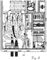
- Figure 4 illustrates an electric drive 500 according to an embodiment.
- the example six cable connection terminal 200 connected to six cables 300, respectively, are each equipped with a separate measuring arrangement 100 for measuring the temperature of the respective cable connection terminal.
- the exemplary cables 300 in the example of Figure 4 could be three input power phase cables and three output power phase cables of the electric drive, for example.
- only some cable terminals 200 of an electric drive 500, or all of them, could be equipped with measuring arrangements 100.
- one measuring arrangement comprises two or more temperature sensors and is configured to measure the temperature of two or more different cable connection terminals of the electric drive 500.
- the measuring arrangement 100 may be configured to perform the measuring and transmitting of the temperature of the cable connection terminal 200 of the electric drive continuously or at predetermined intervals.
- the measured temperature is transmitting from the measuring arrangement to a temperature monitoring entity.
- a temperature monitoring entity may be any kind of physical or logical arrangement or system performing temperature monitoring of the electric drive in question, for example.
- FIG. 5 illustrates a simplified block diagram of a monitoring system according to an embodiment.
- the connections shown in Figure 5 are logical connections and the actual physical connections may be different.
- two electric drives 500 are illustrated each of which may comprise a plurality of measuring arrangements 100 according to any one of the embodiments described herein.
- the example further shows a temperature monitoring arrangement (e.g. apparatus, device, equipment) 700, which is configured to obtain the temperature information transmitted by at least one of the at least one measuring arrangements 100.
- the temperature monitoring arrangement 700 may be located on a remote site. As shown in the example, the temperature information may be transmitted from the at least one of the at least one measuring arrangements 100 to the temperature monitoring arrangement 700 directly and/or indirectly via one or more further elements.
- the communication connections may utilize a fixed communication system or a wireless communication system or a communication system utilizing both fixed networks and wireless networks, for example.
- Figure 5 also illustrates a cloud platform 600, for example, in which network devices, computing devices and/or storage devices may provide shared resources, such as a database 610 for storing process data such as temperature data.
- a cloud platform 600 may be based on The Internet of Things (loT), which refers to the networking of physical devices (also referred to as 'connected devices' and 'smart devices'), such as vehicles, home appliances, machines, computers and other items that are embedded with electronics, software, sensors, actuators, and network connectivity that enables these objects to collect and exchange data.
- IoT allows objects to be sensed and/or controlled remotely across existing network infrastructure.
- the Industrial Internet of Things is the use of loT technologies in e.g. the manufacturing industry. It may incorporate machine learning and big data technology, harnessing the sensor data, machine-to-machine communication and automation technologies that have existed in industrial settings. IIoT also provides mechanisms to connect industrial devices to a cloud computing platform and to transfer information to the cloud platform for performing various operations, such as remote monitoring, e.g. for predictive maintenance, on the industrial data. It is apparent to a person skilled in the art that such systems also comprise other equipment, functional entities and structures, some of which may be used in or for big data, data management, and communication in the system or in one part of the system. They, as well as the possible protocols used, are considered known by persons skilled in the art.
- the temperature data transmitted from one measuring arrangements 100 could be stored to a database 610, managed by any suitable database management system, within the cloud platform 600, from where the one or more temperature monitoring arrangements 700 may obtain the data, for example.
- the temperature monitoring arrangement 700 may comprise a condition monitoring tool configured, for example, to identify in one or more condition parameters, such as temperature, changes indicative of a developing fault.
- condition of the cable connection terminals 200 can be monitored even remotely on the basis of the measured temperatures thereof.
- Another example of such a monitoring tool includes a possibly remote performance optimization tool, for example, to identify sources of issues indicative of e.g. increased energy consumption, and/or increased emissions.
- the purpose and actual functionality of the temperature monitoring arrangement 700 and its internal structure may vary and may depend on the system architecture and characteristics, for example.
- a condition monitoring of the cable connection terminal 200 of the electric drive 500 may be based on a trend analysis of the measured temperature data.
- condition monitoring may comprise collecting, over a period of time, a set of values of the measured temperature of the cable connection terminal 200 of the electric drive 500 transmitted from the measuring arrangement 100 to the temperature monitoring entity 70, and forming a temperature trend pattern on the basis of the collected set of values of the measured temperature.
- a trend pattern may be a trend line, e.g. a linear trend line or a non-linear trend line, or a trend curve, for example.
- a trend pattern can be formed by using any known method.
- a condition of the cable connection terminal 200 of the electric drive 500 can be determined on the basis of the formed temperature trend pattern.
- Such determination may comprise e.g. comparing the formed temperature trend pattern to one or more predetermined threshold values and/or patterns, which may be determined on the basis of an expected temperature, historical temperature data and/or calculations.
- Such calculations may be based on e.g. current and/or voltage values of the cable connection terminal 200, or any quantities in known relationship thereto, for example.
- the control arrangement 102 or other means controlling the one or more measuring arrangements 100, or one or more elements thereof, and/or the temperature monitoring arrangement 700, according to any one of the embodiments described herein, or any combination thereof, may be implemented as one physical unit or as two or more separate physical units that are configured to implement the functionality of the various embodiments.
- Any apparatus for implementing the functionality according to any one of the embodiments may be implemented at least partly by means of one or more computers or corresponding digital signal processing (DSP) equipment provided with suitable software, for example.
- DSP digital signal processing
- Such a computer or digital signal processing equipment preferably comprises at least a working memory (RAM) providing storage area for arithmetical operations and a central processing unit (CPU), such as a general-purpose digital signal processor.
- RAM working memory
- CPU central processing unit
- the CPU may comprise a set of registers, an arithmetic logic unit, and a CPU control unit.
- the CPU control unit is controlled by a sequence of program instructions transferred to the CPU from the RAM.
- the CPU control unit may contain a number of microinstructions for basic operations. The implementation of microinstructions may vary depending on the CPU design.
- the program instructions may be coded by a programming language, which may be a high-level programming language, such as C, Java, etc., or a low-level programming language, such as a machine language, or an assembler.
- the computer may also have an operating system, which may provide system services to a computer program written with the program instructions.
- the computer or other apparatus implementing any of the embodiments, or a part thereof, may further comprise suitable input means for receiving e.g. measurement and/or control data, and output means for outputting e.g. control data. It is also possible to use a specific integrated circuit or circuits, such as application-specific integrated circuits (ASIC), and/or programmable logic devices (PLD), such as a field-programmable gate array (FPGA), and/or discrete electric components and devices for implementing the functionality according to any one of the embodiments.
- ASIC application-specific integrated circuits
- PLD programmable logic devices
- FPGA field-programmable gate array
- any of the embodiments is implemented by software
- such software or program may be provided as a computer program product comprising computer program code which, when run on a computer, causes the computer or corresponding computing device to perform the functionality according to the embodiment.
- Such a computer program code may be stored or generally embodied on a computer readable medium, such as suitable memory, e.g. a flash memory or an optical memory, from which it is loadable to the unit or units executing the program code.
- suitable memory e.g. a flash memory or an optical memory
- such a computer program code implementing the embodiment may be loaded to the unit or units executing the computer program code via a suitable data network, for example, and it may replace or update a possibly existing program code.
Landscapes
- Physics & Mathematics (AREA)
- General Physics & Mathematics (AREA)
- Arrangements For Transmission Of Measured Signals (AREA)
- Measuring Temperature Or Quantity Of Heat (AREA)
Abstract
A measuring arrangement and method for measuring a temperature of a cable connection terminal of an electric drive, the measuring arrangement (100) comprising measuring means (110, 120) configured to measure the temperature of the cable connection terminal (200) of the electric drive, the measuring means (110, 120) comprising at least one temperature sensor configured to be thermally connected to the cable connection terminal (200) of the electric drive; and transmitting means configured to transmit the measured temperature from the measuring arrangement (100).
Description
- The present invention relates to an arrangement and a method for measuring a temperature of a cable connection terminal of an electric drive.
- An electric drive generally refers to an electronic apparatus, which may be used to regulate the performance of an electric motor or another kind of load, for example. An electric drive may control the power, frequency and/or current supplied to the load, for instance. An electric drive and e.g. an electric motor controlled by the electric drive may form an electric drive system. An electric drive may comprise one or more electric power converter units or modules, such as rectifiers, inverters or frequency converters, for example.
- The electric drive may comprise cable connection terminals for connecting various input and/or output cables such as input power cables supplying power to the electric drive and output power cables supplying power from the electric drive to the load, such as a motor, for example.
- If the connection of the cable to the cable connection terminal is loose or otherwise defective, the temperature of the cable connection terminal may rise and/or vary abnormally. Thus, e.g. condition monitoring of the cable connections to the cable connection terminals of the electric drive may be done by measuring the temperatures of the cable connection terminals. This may be performed by using e.g. an infrared thermometer which enables to measure the temperature without touching the cable connection terminal possibly under tension.
- A problem related to the above solution is that the cable connection terminals of the electric drive may be located inside the housing of the electric drive possibly behind other components and/or the electric drive may be located in a difficult to reach location. Then, in order to measure the temperature e.g. with an infrared thermometer, which requires a physical view to the measured object, the measuring could be complicated and time consuming.
- An object of the present invention is thus to provide a method and an apparatus for implementing the method so as to overcome the above problems or at least to alleviate them. The objects of the invention are achieved by a measuring arrangement, and a method, which are characterized by what is stated in the independent claims. The preferred embodiments of the invention are disclosed in the dependent claims.
- The invention is based on the idea of thermally connecting a temperature sensor to a cable connection terminal of the electric drive, measuring the temperature of the cable connection terminal by the temperature sensor connected to the cable connection terminal, and transmitting the measured temperature.
- An advantage of the solution of the invention is that it enables the monitoring of the temperature of the cable connection terminal to be performed remotely.
- In the following the invention will be described in greater detail by means of exemplary embodiments with reference to the accompanying drawings, in which
-
Figure 1 illustrates a measuring arrangement according to an embodiment; -
Figure 2 illustrates a measuring arrangement according to an embodiment; -
Figure 3 illustrates a block diagram according to an embodiment; -
Figure 4 illustrates an electric drive according to an embodiment; and -
Figure 5 illustrates a block diagram according to an embodiment. - The following embodiments are exemplary. Although the description may refer to "an", "one", or "some" embodiment(s) in several locations, this does not necessarily mean that each such reference is to the same embodiment(s), or that the feature only applies to a single embodiment, for example. Single features of different embodiments may also be combined to provide other embodiments. Generally, all terms and expressions used should be interpreted broadly and they are intended to illustrate, not to restrict, the embodiments. The figures only show components necessary for understanding the various embodiments. The number and/or shape of the various elements, and generally their implementation, could vary from the examples shown in the figures.
- According to an embodiment, a measuring arrangement for measuring a temperature of a cable connection terminal of an electric drive, comprises measuring means configured to measure the temperature of the cable connection terminal, the measuring means comprising at least one temperature sensor configured to be thermally connected to the cable connection terminal of the electric drive, and transmitting means configured to transmit the measured temperature from the measuring arrangement. According to an embodiment, a method for measuring a temperature of a cable connection terminal of an electric drive, comprises thermally connecting a temperature sensor of a measuring arrangement to the cable connection terminal of the electric drive, measuring the temperature of the cable connection terminal by the temperature sensor of the measuring arrangement thermally connected to the cable connection terminal, and transmitting the measured temperature from the measuring arrangement to a temperature monitoring entity. Term 'electric drive' herein generally refers to an electronic apparatus, which may be used to regulate the performance of an electric motor or another load. An electric drive may control the power, frequency and/or current supplied to the motor, for instance. An electric drive and an electric motor controlled by the electric drive may form an electric drive system. An electric drive may comprise one or more electric power converter units or modules, such as rectifiers, inverters or frequency converters, for example. Herein term 'inverter' generally refers to an electronic device or circuitry that is able to convert direct current to alternating current. An example of the inverter is a semiconductor bridge implemented by means of controllable semiconductor switches, such as IGBTs (Insulated-Gate Bipolar Transistor) or FETs (Field-Effect Transistor), which are controlled according to a modulation or control scheme used.
-
Figures 1 and2 show an example of ameasuring arrangement 100 according to an embodiment. Theexemplary measuring arrangement 100 is connected to acable connection terminal 200 of an electric drive. The exemplarycable connection terminal 200 comprises anelectrical connecting part 210, such as a busbar, or a part thereof, or a similar electric conductor structure, and suitable fastening means comprising e.g. one ormore bolts 220 andnuts 221 for clamping or fastening acable 300 to thecable connection terminal 200. The structure of thecable connection terminal 200 may vary from the example shown and may depend e.g. on the voltage level and/or current level of the electrical connection in question. The cable connection terminal may be an input power cable connection terminal or an output power cable connection terminal of the electric drive, for example. Thecable 300 in the illustrated examples is provided with a cable shoe (a cable lug) 310 to assist the connection of thecable 300 end to thecable connection terminal 200. However, depending on the structure of thecable connection terminal 200 and/or of thecable 300, such acable shoe 310 may not be needed and thecable 300 end could be directly connected to thecable connection terminal 200. - In the example illustrated in
Figures 1 and2 themeasuring arrangement 100 comprises aconnection part 110 and ameasuring unit 120 housing other elements of theexemplary measuring arrangement 100. There could also be more than onesuch connection parts 110, connected in parallel and/or in series with each other, for connecting themeasuring arrangement 100 to thecable connection terminal 200. According to an embodiment, themeasuring arrangement 100 comprises thermal connection means configured to thermally indirectly connect the at least one temperature sensor to the cable connection terminal of the electric drive via the thermal connection means. Accordingly, the at least oneconnection part 110 may function as such thermal connection means and provide at least a thermal connection between thecable connection terminal 200 and themeasuring unit 120. For this purpose, the at least oneconnection part 110 may be made of thermally conducting material, such as metal material. The exemplary at least oneconnection part 110 may also physically fasten themeasuring arrangement 100 to thecable connection terminal 200 such that no further fastening of themeasuring arrangement 100 is needed. Alternatively, themeasuring arrangement 100, or some part or parts thereof, could be physically fastened to another part within the electric drive such that mainly a thermal connection between themeasuring arrangement 100 and thecable connection terminal 200 is provided, for example. Such one ormore connection parts 110 providing the thermal connection and/or physical fastening of themeasuring arrangement 100 is preferably suitably shaped such that it can be connected to thecable connection terminal 200 without interfering the functioning of thecable connection terminal 200. In the example ofFigures 1 and2 the at least oneconnection part 110 comprises, at least partly, a sheet-like structure, which can be sandwiched between thecable connection terminal 200 and the end of thecable 300 connected to theconnection terminal 200. As a result, theconnection part 110 may accurately convey the actual temperature in thecable connection terminal 200 to themeasuring unit 120. The thickness of such a sheet-like structure can be suitably selected such that it is thin enough to fit to thecable connection terminal 200 but at the same time thick enough to provide adequate physical fastening of themeasuring arrangement 100 to thecable connection terminal 200, for example. The sheet-like structure of theconnection part 110 may also comprise one or more holes for possible fasteningbolts 220 or screws, for instance, as also shown in the example ofFigures 1 and2 to further facilitate the fastening of themeasuring arrangement 100 to thecable connection terminal 200. -
Figure 3 shows a simplified block diagram of theexemplary measuring unit 120. It should be noted that instead of onesuch measuring unit 120 or a similar entity, the elements and functionality thereof, as described in the following, could be distribute between two or more physically and/or logically separate units or entities within themeasuring arrangement 100. According to an embodiment, themeasuring arrangement 100 comprises measuring means configured to measure the temperature of thecable connection terminal 200 of the electric drive. Such measuring means may comprise at least onetemperature sensor 101 configured to be thermally connected to thecable connection terminal 200 of the electric drive. The at least onetemperature sensor 101 may be housed within theexemplary measuring unit 120 as shown in the example. According to an embodiment, the at least onetemperature sensor 101 may be configured to be thermally directly connected to thecable connection terminal 200 of the electric drive. Accordingly, the at least onetemperature sensor 101 could be directly connected to thecable connection terminal 200 hence providing a direct thermal connection. According to an embodiment, the at least onetemperature sensor 101 may be configured to be thermally indirectly connected to thecable connection terminal 200 of the electric drive. Such indirect thermal connection may be provided via one or moreintermediate parts 110 of thermally conducting material providing the thermal connection between the at least onetemperature sensor 101 and thecable connection terminal 200 of the electric drive, as shown in the example ofFigures 1 and2 . In the example ofFigures 1 and2 thetemperature sensor 101 may be arranged in direct thermal connection to the at least oneconnection part 110. There could also be one or more electrically insulating but thermally conducting layers (not shown in the figures) provided between the temperature sensor and the at least oneconnection part 110, for example. The type of the at least onetemperature sensor 101 may be selected according to characteristics of the electrical connection provided by thecable connection terminal 200 of the electric drive, for example. The at least onetemperature sensor 101 may be an electrical temperature sensor, such as a thermistor, a thermocouple, a resistance thermometer, a silicon bandgap temperature sensor, or any combination thereof, or an integrated circuit sensor, for example. According to an embodiment, the measuring means of the measuringarrangement 100 may further comprise acontrol arrangement 102, which is configured to measure the temperature of thecable connection terminal 200 by the at least onetemperature sensor 101 thermally connected to the cable connection terminal. The control arrangement 201 may also provide other functionalities within the measuringarrangement 100 according to any one of the embodiments described herein. According to an embodiment, the measuringarrangement 100 may comprise transmitting means configured to transmit the measured temperature from the measuring arrangement. Accordingly, theexemplary measuring unit 120 comprises a transmitter (TX) 103, which may be a wireless transmitter or a wired transmitter, or a combination thereof, and which is configured to send the measured temperature data from the measuringarrangement 100. Also a combined (wireless and/or wired) transmitter-receiver, i.e. a transceiver, could be used, which could enable the measuringarrangement 100 to receive control and/or other data, for example. Such a wireless transmitter or transceiver could utilize Bluetooth, Wi-Fi, cellular and/or a low-power wide-area network (LPWAN) technology, for example, or any other wireless communication technology. Such a wired transmitter or transceiver could utilize Ethernet technology, such as any Industrial Ethernet (IE) protocol, for example. Theexemplary measuring unit 120 further comprises a power supply (PS) 104, which may provide the operating power for the measuringarrangement 100. According to an embodiment, the measuringarrangement 100 comprises power supplying means configured to transfer electric power from thecable connection terminal 200 or from an electric circuit connected to the cable connection terminal to the measuring arrangement by means of inductive coupling and/or capacitive coupling. Accordingly, thepower supply 104 of theexemplary measuring unit 120 could be configured to provide such wireless transfer of electric power by means of inductive coupling and/or capacitive coupling from thecable connection terminal 200 or from an electric circuit connected to the cable connection terminal to the measuring arrangement, such as thecable 300. For this purpose, thepower supply 104 may comprise (not shown separately) a suitable coupling device(s), such as a coil(s), electrode(s) and/or antenna(s) for obtaining electric power wirelessly from thecable connection terminal 200 or from an electric circuit connected thereto. Additionally or alternatively, thepower supply 104 of theexemplary measuring unit 120 may comprise one or more batteries, for instance. The measuringarrangement 100 could further comprise, e.g. within thecontrol arrangement 102, a memory, such as a buffer memory, for at least temporarily storing e.g. measurement data. -
Figure 4 illustrates anelectric drive 500 according to an embodiment. In the example sixcable connection terminal 200 connected to sixcables 300, respectively, are each equipped with aseparate measuring arrangement 100 for measuring the temperature of the respective cable connection terminal. Theexemplary cables 300 in the example ofFigure 4 could be three input power phase cables and three output power phase cables of the electric drive, for example. It should be noted that only somecable terminals 200 of anelectric drive 500, or all of them, could be equipped with measuringarrangements 100. Moreover, it is also possible that one measuring arrangement comprises two or more temperature sensors and is configured to measure the temperature of two or more different cable connection terminals of theelectric drive 500. - According to an embodiment, the measuring
arrangement 100 may be configured to perform the measuring and transmitting of the temperature of thecable connection terminal 200 of the electric drive continuously or at predetermined intervals. According to an embodiment, the measured temperature is transmitting from the measuring arrangement to a temperature monitoring entity. Such a temperature monitoring entity may be any kind of physical or logical arrangement or system performing temperature monitoring of the electric drive in question, for example. -
Figure 5 illustrates a simplified block diagram of a monitoring system according to an embodiment. The connections shown inFigure 5 are logical connections and the actual physical connections may be different. In the example twoelectric drives 500 are illustrated each of which may comprise a plurality of measuringarrangements 100 according to any one of the embodiments described herein. The example further shows a temperature monitoring arrangement (e.g. apparatus, device, equipment) 700, which is configured to obtain the temperature information transmitted by at least one of the at least one measuringarrangements 100. Thetemperature monitoring arrangement 700 may be located on a remote site. As shown in the example, the temperature information may be transmitted from the at least one of the at least one measuringarrangements 100 to thetemperature monitoring arrangement 700 directly and/or indirectly via one or more further elements. The communication connections may utilize a fixed communication system or a wireless communication system or a communication system utilizing both fixed networks and wireless networks, for example.Figure 5 also illustrates acloud platform 600, for example, in which network devices, computing devices and/or storage devices may provide shared resources, such as adatabase 610 for storing process data such as temperature data. Such acloud platform 600 may be based on The Internet of Things (loT), which refers to the networking of physical devices (also referred to as 'connected devices' and 'smart devices'), such as vehicles, home appliances, machines, computers and other items that are embedded with electronics, software, sensors, actuators, and network connectivity that enables these objects to collect and exchange data. IoT allows objects to be sensed and/or controlled remotely across existing network infrastructure. The Industrial Internet of Things (IIoT) is the use of loT technologies in e.g. the manufacturing industry. It may incorporate machine learning and big data technology, harnessing the sensor data, machine-to-machine communication and automation technologies that have existed in industrial settings. IIoT also provides mechanisms to connect industrial devices to a cloud computing platform and to transfer information to the cloud platform for performing various operations, such as remote monitoring, e.g. for predictive maintenance, on the industrial data. It is apparent to a person skilled in the art that such systems also comprise other equipment, functional entities and structures, some of which may be used in or for big data, data management, and communication in the system or in one part of the system. They, as well as the possible protocols used, are considered known by persons skilled in the art. Therefore, they need not to be discussed in more detail herein. Accordingly, the temperature data transmitted from one measuringarrangements 100 could be stored to adatabase 610, managed by any suitable database management system, within thecloud platform 600, from where the one or moretemperature monitoring arrangements 700 may obtain the data, for example. Thetemperature monitoring arrangement 700 may comprise a condition monitoring tool configured, for example, to identify in one or more condition parameters, such as temperature, changes indicative of a developing fault. Thus, the condition of thecable connection terminals 200 can be monitored even remotely on the basis of the measured temperatures thereof. Another example of such a monitoring tool includes a possibly remote performance optimization tool, for example, to identify sources of issues indicative of e.g. increased energy consumption, and/or increased emissions. The purpose and actual functionality of thetemperature monitoring arrangement 700 and its internal structure may vary and may depend on the system architecture and characteristics, for example. - According to an embodiment, a condition monitoring of the
cable connection terminal 200 of theelectric drive 500, performed e.g. by thetemperature monitoring arrangement 700 and/or by another entity, may be based on a trend analysis of the measured temperature data. According to an embodiment, such condition monitoring may comprise collecting, over a period of time, a set of values of the measured temperature of thecable connection terminal 200 of theelectric drive 500 transmitted from the measuringarrangement 100 to the temperature monitoring entity 70, and forming a temperature trend pattern on the basis of the collected set of values of the measured temperature. Such a trend pattern may be a trend line, e.g. a linear trend line or a non-linear trend line, or a trend curve, for example. Moreover, such a trend pattern can be formed by using any known method. Then, a condition of thecable connection terminal 200 of theelectric drive 500 can be determined on the basis of the formed temperature trend pattern. Such determination may comprise e.g. comparing the formed temperature trend pattern to one or more predetermined threshold values and/or patterns, which may be determined on the basis of an expected temperature, historical temperature data and/or calculations. Such calculations may be based on e.g. current and/or voltage values of thecable connection terminal 200, or any quantities in known relationship thereto, for example. - The
control arrangement 102 or other means controlling the one ormore measuring arrangements 100, or one or more elements thereof, and/or thetemperature monitoring arrangement 700, according to any one of the embodiments described herein, or any combination thereof, may be implemented as one physical unit or as two or more separate physical units that are configured to implement the functionality of the various embodiments. Any apparatus for implementing the functionality according to any one of the embodiments may be implemented at least partly by means of one or more computers or corresponding digital signal processing (DSP) equipment provided with suitable software, for example. Such a computer or digital signal processing equipment preferably comprises at least a working memory (RAM) providing storage area for arithmetical operations and a central processing unit (CPU), such as a general-purpose digital signal processor. The CPU may comprise a set of registers, an arithmetic logic unit, and a CPU control unit. The CPU control unit is controlled by a sequence of program instructions transferred to the CPU from the RAM. The CPU control unit may contain a number of microinstructions for basic operations. The implementation of microinstructions may vary depending on the CPU design. The program instructions may be coded by a programming language, which may be a high-level programming language, such as C, Java, etc., or a low-level programming language, such as a machine language, or an assembler. The computer may also have an operating system, which may provide system services to a computer program written with the program instructions. The computer or other apparatus implementing any of the embodiments, or a part thereof, may further comprise suitable input means for receiving e.g. measurement and/or control data, and output means for outputting e.g. control data. It is also possible to use a specific integrated circuit or circuits, such as application-specific integrated circuits (ASIC), and/or programmable logic devices (PLD), such as a field-programmable gate array (FPGA), and/or discrete electric components and devices for implementing the functionality according to any one of the embodiments. - If at least part of the functionality of any of the embodiments is implemented by software, such software or program may be provided as a computer program product comprising computer program code which, when run on a computer, causes the computer or corresponding computing device to perform the functionality according to the embodiment. Such a computer program code may be stored or generally embodied on a computer readable medium, such as suitable memory, e.g. a flash memory or an optical memory, from which it is loadable to the unit or units executing the program code. In addition, such a computer program code implementing the embodiment may be loaded to the unit or units executing the computer program code via a suitable data network, for example, and it may replace or update a possibly existing program code.
- It will be obvious to a person skilled in the art that, as the technology advances, the inventive concept can be implemented in various ways. The invention and its embodiments are not limited to the examples described above but may vary within the scope of the claims.
Claims (15)
- A measuring arrangement for measuring a temperature of a cable connection terminal of an electric drive, comprising:measuring means (110, 120) configured to measure the temperature of the cable connection terminal (200) of the electric drive (500), the measuring means comprising at least one temperature sensor (101) configured to be thermally connected to the cable connection terminal (200) of the electric drive (500); andtransmitting means (103) configured to transmit the measured temperature from the measuring arrangement (100).
- A measuring arrangement as claimed in claim 1, wherein the measuring arrangement (100) is configured to perform the measuring and transmitting continuously or at predetermined intervals.
- A measuring arrangement as claimed in claim 1 or 2, wherein the transmitting means (103) are configured to transmit the measured temperature in a wireless and/or wired manner.
- A measuring arrangement as claimed in claim 1, 2 or 3, wherein the at least one temperature sensor (101) is configured to be thermally directly connected to the cable connection terminal (200) of the electric drive (500).
- A measuring arrangement as claimed in claim 1, 2 or 3, comprising thermal connection means (110) configured to thermally indirectly connect the at least one temperature sensor (101) to the cable connection terminal (200) of the electric drive (500) via the thermal connection means (110).
- A measuring arrangement as claimed in any one of claims 1 to 5, comprising power supplying means (104) configured to transfer electric power from the cable connection terminal (200) or from an electric circuit connected to the cable connection terminal (200) to the measuring arrangement (100) by means of inductive coupling and/or capacitive coupling.
- An electric drive, comprising:at least one cable connection terminal (200); andat least one measuring arrangement (100) as claimed in any one of claims 1 to 6, wherein the at least one temperature sensor (101) of the measuring arrangement (100) is thermally connected to the cable connection terminal (200) of the electric drive (500).
- A monitoring system, comprising:at least one measuring arrangement (100) as claimed in any one of claims 1 to 6; andat least one temperature monitoring arrangement (700) configured to obtain the temperature information transmitted by at least one of the at least one measuring arrangements (100).
- A monitoring system as claimed in claim 8, comprising:at least one database (610) configured to receive temperature information transmitted by the at least one measuring arrangement (100),wherein the at least one temperature monitoring arrangement (700) is configured to obtain the temperature information from the at least one database (610).
- A method for measuring a temperature of a cable connection terminal (200) of an electric drive (500), comprising:thermally connecting a temperature sensor (101) of a measuring arrangement (100) to the cable connection terminal (200) of the electric drive (500);measuring the temperature of the cable connection terminal (200) by the temperature sensor (101) of the measuring arrangement (100) thermally connected to the cable connection terminal (200); andtransmitting the measured temperature from the measuring arrangement (100) to a temperature monitoring entity (700).
- A method as claimed in claim 10, wherein the measuring is performed continuously or at predetermined intervals.
- A method as claimed in claim 10 or 11, wherein the measured temperature is transmitted from the measuring arrangement (100) to the temperature monitoring entity (700) in a wireless and/or wired manner.
- A method as claimed in claim 10, 11 or 12, wherein the temperature sensor (101) of the measuring arrangement (100) is thermally directly connected to the cable connection terminal (200) of the electric drive (500) or thermally indirectly connected to the cable connection terminal (200) of the electric drive (500).
- A method as claimed in any one of claims 10 to 13, comprising transferring electric power from the cable connection terminal (200) or from an electric circuit connected to the cable connection terminal (200) to the measuring arrangement (100) by means of inductive coupling and/or capacitive coupling.
- A method as claimed in any one of claims 10 to 14, comprising:collecting, over a period of time, a set of values of the measured temperature of the cable connection terminal (200) of the electric drive (500) transmitted from the measuring arrangement (100) to the temperature monitoring entity (700);forming a temperature trend pattern on the basis of the collected set of values of the measured temperature; anddetermining, on the basis of the formed temperature trend pattern, a condition of the cable connection terminal (200) of the electric drive (500).
Priority Applications (3)
| Application Number | Priority Date | Filing Date | Title |
|---|---|---|---|
| EP20182836.5A EP3933361A1 (en) | 2020-06-29 | 2020-06-29 | Arrangement and method for measuring temperature of cable connection terminal of electric drive |
| CN202121415798.8U CN216349195U (en) | 2020-06-29 | 2021-06-24 | Measuring device, electric drive and monitoring system |
| DE202021103459.9U DE202021103459U1 (en) | 2020-06-29 | 2021-06-29 | Arrangement for measuring the temperature of a cable connection connection of an electric drive |
Applications Claiming Priority (1)
| Application Number | Priority Date | Filing Date | Title |
|---|---|---|---|
| EP20182836.5A EP3933361A1 (en) | 2020-06-29 | 2020-06-29 | Arrangement and method for measuring temperature of cable connection terminal of electric drive |
Publications (1)
| Publication Number | Publication Date |
|---|---|
| EP3933361A1 true EP3933361A1 (en) | 2022-01-05 |
Family
ID=71266482
Family Applications (1)
| Application Number | Title | Priority Date | Filing Date |
|---|---|---|---|
| EP20182836.5A Withdrawn EP3933361A1 (en) | 2020-06-29 | 2020-06-29 | Arrangement and method for measuring temperature of cable connection terminal of electric drive |
Country Status (3)
| Country | Link |
|---|---|
| EP (1) | EP3933361A1 (en) |
| CN (1) | CN216349195U (en) |
| DE (1) | DE202021103459U1 (en) |
Cited By (1)
| Publication number | Priority date | Publication date | Assignee | Title |
|---|---|---|---|---|
| KR102567220B1 (en) * | 2022-08-11 | 2023-08-16 | (주)화인파워엑스 | RF temperature sensor for switchboard terminals, and switchboard device equipped with the RF temperature sensor, and monitoring system of a temperature of the switchboard device |
Families Citing this family (1)
| Publication number | Priority date | Publication date | Assignee | Title |
|---|---|---|---|---|
| ES3058888T3 (en) * | 2022-05-25 | 2026-03-13 | Nexans | Cross-bonding box integrity monitoring |
Citations (1)
| Publication number | Priority date | Publication date | Assignee | Title |
|---|---|---|---|---|
| CN205453072U (en) * | 2016-03-25 | 2016-08-10 | 国网山东省电力公司济宁供电公司 | Totally enclosed switchgear cable terminal and temperature measurement system |
-
2020
- 2020-06-29 EP EP20182836.5A patent/EP3933361A1/en not_active Withdrawn
-
2021
- 2021-06-24 CN CN202121415798.8U patent/CN216349195U/en active Active
- 2021-06-29 DE DE202021103459.9U patent/DE202021103459U1/en active Active
Patent Citations (1)
| Publication number | Priority date | Publication date | Assignee | Title |
|---|---|---|---|---|
| CN205453072U (en) * | 2016-03-25 | 2016-08-10 | 国网山东省电力公司济宁供电公司 | Totally enclosed switchgear cable terminal and temperature measurement system |
Cited By (1)
| Publication number | Priority date | Publication date | Assignee | Title |
|---|---|---|---|---|
| KR102567220B1 (en) * | 2022-08-11 | 2023-08-16 | (주)화인파워엑스 | RF temperature sensor for switchboard terminals, and switchboard device equipped with the RF temperature sensor, and monitoring system of a temperature of the switchboard device |
Also Published As
| Publication number | Publication date |
|---|---|
| CN216349195U (en) | 2022-04-19 |
| DE202021103459U1 (en) | 2021-11-04 |
Similar Documents
| Publication | Publication Date | Title |
|---|---|---|
| EP3203250B1 (en) | Method and device for estimating a level of damage or a lifetime expectation of a power semiconductor module | |
| CN216349195U (en) | Measuring device, electric drive and monitoring system | |
| US12062921B2 (en) | Smart power system | |
| US8170817B2 (en) | Method and device for determining the electrical loadability of overhead lines by means of temperature measurement | |
| US10453767B2 (en) | Control device and method for monitoring a function of a semiconductor component during the operation thereof and electrical assembly having a control device | |
| CN109298306A (en) | Semiconductor Failure Prediction | |
| EP3767312B1 (en) | Current sampling method and current sampling circuit | |
| EP3779386B1 (en) | System and method for modeling thermal circuits | |
| CN106445785A (en) | Computer fault alarm system and control method | |
| CN116488302A (en) | Integrated intelligent fast charging charger and data intelligent monitoring system | |
| CN113131725A (en) | Intelligent power module based on silicon carbide and application | |
| Wang et al. | Efficient multi-channel thermal monitoring and temperature prediction based on improved linear regression | |
| US20140346898A1 (en) | Junction box having the mppt control function that is individually embedded in a solar cell module, and method for driving same | |
| Qin et al. | Electrothermal management using in-situ junction temperature monitoring for enhanced reliability of SiC-based power electronics | |
| JP6420622B2 (en) | Management unit that transmits and receives state values indicating the state of the solar cell module | |
| US20140052302A1 (en) | Method and sensor node for managing power consumption and power consumption information collection apparatus using the same | |
| Tang et al. | Physics-Informed Intelligent Thermal Model for SiC Power Modules with High Generalization | |
| KR101924478B1 (en) | Junction box for a solar cell module contains the electric power state measurement and display functions and id setting method | |
| CN111819760A (en) | Monitoring of high or medium pressure equipment | |
| JP7208093B2 (en) | setting system | |
| CN115342938A (en) | Method and device for determining junction temperature of power semiconductor device | |
| Phuc et al. | Real-Time Monitoring Electric Motor Conditions Utilizing IoT and Deep Learning Algorithm | |
| Bentivogli et al. | Enabling predictive maintenance on electric motors through a self-sustainable wireless sensor node | |
| EP3346384B1 (en) | Industrial device fault management in a communications system | |
| CN120142828B (en) | Power component performance testing method and system based on thermal feedback topology |
Legal Events
| Date | Code | Title | Description |
|---|---|---|---|
| PUAI | Public reference made under article 153(3) epc to a published international application that has entered the european phase |
Free format text: ORIGINAL CODE: 0009012 |
|
| STAA | Information on the status of an ep patent application or granted ep patent |
Free format text: STATUS: THE APPLICATION HAS BEEN PUBLISHED |
|
| AK | Designated contracting states |
Kind code of ref document: A1 Designated state(s): AL AT BE BG CH CY CZ DE DK EE ES FI FR GB GR HR HU IE IS IT LI LT LU LV MC MK MT NL NO PL PT RO RS SE SI SK SM TR |
|
| B565 | Issuance of search results under rule 164(2) epc |
Effective date: 20201130 |
|
| STAA | Information on the status of an ep patent application or granted ep patent |
Free format text: STATUS: THE APPLICATION IS DEEMED TO BE WITHDRAWN |
|
| 18D | Application deemed to be withdrawn |
Effective date: 20220706 |