EP3933317A1 - A cooling appliance having an improved handle mechanism - Google Patents
A cooling appliance having an improved handle mechanism Download PDFInfo
- Publication number
- EP3933317A1 EP3933317A1 EP21176407.1A EP21176407A EP3933317A1 EP 3933317 A1 EP3933317 A1 EP 3933317A1 EP 21176407 A EP21176407 A EP 21176407A EP 3933317 A1 EP3933317 A1 EP 3933317A1
- Authority
- EP
- European Patent Office
- Prior art keywords
- tabs
- handle
- door
- pair
- supports
- Prior art date
- Legal status (The legal status is an assumption and is not a legal conclusion. Google has not performed a legal analysis and makes no representation as to the accuracy of the status listed.)
- Withdrawn
Links
- 238000001816 cooling Methods 0.000 title claims abstract description 26
- 230000000063 preceeding effect Effects 0.000 claims 3
- 230000000694 effects Effects 0.000 description 9
- 239000011111 cardboard Substances 0.000 description 2
- 238000012423 maintenance Methods 0.000 description 2
- 238000000034 method Methods 0.000 description 2
- 230000003247 decreasing effect Effects 0.000 description 1
- 230000001419 dependent effect Effects 0.000 description 1
Images

Classifications
-
- E—FIXED CONSTRUCTIONS
- E05—LOCKS; KEYS; WINDOW OR DOOR FITTINGS; SAFES
- E05B—LOCKS; ACCESSORIES THEREFOR; HANDCUFFS
- E05B3/00—Fastening knobs or handles to lock or latch parts
-
- E—FIXED CONSTRUCTIONS
- E05—LOCKS; KEYS; WINDOW OR DOOR FITTINGS; SAFES
- E05B—LOCKS; ACCESSORIES THEREFOR; HANDCUFFS
- E05B1/00—Knobs or handles for wings; Knobs, handles, or press buttons for locks or latches on wings
- E05B1/0015—Knobs or handles which do not operate the bolt or lock, e.g. non-movable; Mounting thereof
-
- F—MECHANICAL ENGINEERING; LIGHTING; HEATING; WEAPONS; BLASTING
- F25—REFRIGERATION OR COOLING; COMBINED HEATING AND REFRIGERATION SYSTEMS; HEAT PUMP SYSTEMS; MANUFACTURE OR STORAGE OF ICE; LIQUEFACTION SOLIDIFICATION OF GASES
- F25D—REFRIGERATORS; COLD ROOMS; ICE-BOXES; COOLING OR FREEZING APPARATUS NOT OTHERWISE PROVIDED FOR
- F25D23/00—General constructional features
- F25D23/02—Doors; Covers
- F25D23/028—Details
-
- F—MECHANICAL ENGINEERING; LIGHTING; HEATING; WEAPONS; BLASTING
- F25—REFRIGERATION OR COOLING; COMBINED HEATING AND REFRIGERATION SYSTEMS; HEAT PUMP SYSTEMS; MANUFACTURE OR STORAGE OF ICE; LIQUEFACTION SOLIDIFICATION OF GASES
- F25D—REFRIGERATORS; COLD ROOMS; ICE-BOXES; COOLING OR FREEZING APPARATUS NOT OTHERWISE PROVIDED FOR
- F25D2400/00—General features of, or devices for refrigerators, cold rooms, ice-boxes, or for cooling or freezing apparatus not covered by any other subclass
- F25D2400/32—Removal, transportation or shipping of refrigerating devices from one location to another
Definitions
- the present invention relates to a cooling appliance, in particular to a cooling appliance having an improved handle mechanism.
- the cooling devices are provided with a wide variety of door handles.
- the handles contain many features so as to meet the demand of the customers. In the event of changing the location of the cooling appliance inside the kitchen or moving to a new house, the necessity of changing the swing direction of the door may arise. In such cases, the handle must be switched to the opposing side of the door. Such a procedure requires the attendance of a skilled worker which is unwanted as it causes additional costs.
- Another problem caused by the handles during transportation is that the handle generally protrudes outwards from the door therefore increasing the projectional area and therefore the volume of the cooling appliance. This additional increase in the volume increases the volume of the cooling appliance during transportation.
- KR20070065743A A prior art publication in the technical field of the present invention may be referred to as KR20070065743A among others, the document disclosing a cooling appliance having an handle having simplified assembly and structure.
- WO2015144247A1 A prior art publication in the technical field of the present invention may be referred to as WO2015144247A1 among others, the document disclosing a cooling appliance having a handle wherein the handle has a simplified assembly and structure.
- WO2016177428A1 A prior art publication in the technical field of the present invention may be referred to as WO2016177428A1 among others, the document relating to a handle assembly for use in a household assembly, in particular a cooling appliance.
- An objective of the present invention is to provide a handle having simplified assembly.
- Another objective of the present invention is to provide a handle helping reduce the volume of the card board boxes during the transport by means of the handle being easily disassembled during the transportation.
- Another objective of the present invention is to provide a handle wherein the handle is easy to assemble and disassemble but is impossible to remove from the door by accident.
- the method realized to achieve the aim of the present invention and disclosed in the first claim and the dependent claims comprises a cooling appliance.
- the cooling appliance comprises a body and a door pivotably attached onto the body between a closed and an open position.
- the handle is attached onto the door by a pair of supports wherein the supports are provided on the door.
- the supports are distanced apart by a predetermined length. The length depends on the length of the handle.
- the handle comprises a canal extending almost through its length and the said canal accommodates a pair of tabs in a slidable manner. The pair of tabs slide along the canal between a first position during which the tabs are inserted inside the supports. During first position, the distance between the tabs are at maximum.
- the tabs are in the shape of a bent bar, and they are seated inside the supports from one end during the first position. During the first position, the handle is fixed onto the door. The tabs have a second position during which they slide along the canal and towards each other therefore releasing the said ends from the supports. Thus, the handle is freed from the door.
- the handle comprises a pair of cutouts provided on a rear surface of the handle.
- the cutout facilitates the movement of the tabs inside the canal as it helps the user to reach the tabs easily.
- the handle comprises a pair of biasing means biasing the tabs towards the first position.
- the user pulls the tabs towards each other so as to remove the handle from the door.
- the handle is fixed onto the door, should the user release the tabs.
- An advantageous effect provided by means of the biasing means is that the handle remains attached onto the door in a rigid manner.
- the elements are used as the means the user forces the tabs to slide along the canal.
- the elements have a serrated surface which helps the user to slide the elements conveniently.
- the tabs are configured to be seated inside the supports by means of a slot provided inside the supports.
- the slots and the tabs provide a rigid structure.
- the handle can be attached onto the door in a convenient manner reducing maintenance related costs.
- Another advantageous effect provided by means of this invention is that the structure of the handle and the locking mechanism is simplified reducing the overall costs of the cooling appliance.
- Another advantageous effect provided by means of the handle being easily removable helps reduce the volume of the cooling appliance during transport as the manufacturer can easily remove the handle and store it inside the cooling appliance. Upon arrival to the final user, user may slide the tabs and attach the handle onto the door easily and without the need for a trained staff.
- the present invention relates to a cooling appliance comprising; a body and a door (1) attached to the body between a closed position and an open position; a handle (2), having a canal (3) therein, attached onto an edge of the door (1) by means of a pair of supports (4a,4b) distanced apart from one another on the door (1); a pair of tabs (5a,5b), configured to slide along the canal (3) between a first position during which the tabs (5a,5b) are inserted inside the supports (4a,4b), fixing the handle (2) onto the door (1) and a second position during which the tabs (5a,5b) come out of the supports (4a,4b), releasing the handle (2) from the door (1).
- the tabs (5a,5b) are configured to slide along the canal (3) and inside the handle (2).
- the tabs (5a,5b) slide between a first position during which the tabs (5a,5b) are seated inside the supports (4a,4b), therefore fixing the handle (2) onto the supports (4a,4b).
- the tabs (5a,5b) slide inside the canal (3) and towards each other, releasing the tabs (5a,5b) from the supports (4a,4b) and therefore the handle (2) from the door (1).
- the tabs (5a,5b) provides a convenient assembly of the handle (2) onto the door (1).
- Another advantageous effect provided by means of the tabs (5a,5b) is that the handle (2) can be disassembled during transportation, decreasing the volume of the box and therefore transportation related costs.
- a further advantageous effect provided by means of the tabs (5a,5b) is that the user can easily assemble and disassemble the handle (2) from the door (1) eliminating the need to call for a maintenance staff.
- the handle (2) comprises a pair of cutouts (6a,6b) provided on a rear surface accommodating a first end of the pair of tabs (5a,5b).
- the cutouts (6a,6b) facilitates the sliding movement of the pair of tabs (5a,5b) inside the canal (3).
- the handle (2) comprises a pair of biasing means (7a,7b) biasing the tabs (5a,5b) towards the first position.
- the biasing means (7a,7b) are biasing the tabs (5a,5b) away from each other and towards the supports (4a,4b).
- the user forces the tabs (5a,5b) towards each other, compressing the biasing means (7a,7b) and releases the tabs (5a,5b) as the tabs (5a,5b) are in close vicinity of the supports (4a,4b). Due to the force created by the biasing means (7a,7b), the tabs (5a,5b) are automatically inserted inside the supports (4a,4b).
- accidental removal of the tabs (5a,5b) from the supports (4a,4b) is eliminated.
- the tabs (5a,5b) comprise an element (8a,8b) protruding outward from the cutouts (6a,6b) having a serrated holding surface.
- the elements (8a,8b) are used as the means the user forces the tabs (5a,5b) to slide along the canal (3).
- the serrated surface the elements (8a,8b) provides a strong holding area.
- any surface with a patterned structure can be used so as to increase the gripping force.
- the pair of supports (4a,4b) comprise a slot (9a,9b) configured to form fittingly accommodate the pair of tabs (5a,5b).
- the tabs (5a,5b) are seated inside the slots (9a,9b) form fittingly providing a rigid structure and assembly.
- Another advantageous effect provided by means of the pair of tabs (5a,5b) is that the handle (2) can be easily removed from the door (1).
- Another advantageous effect provided by means of the pair of tabs (5a,5b) is that the handle (2) is rigidly attached onto the door (1), eliminating the possibility of accidental disconnecting of the handle (2) from the door (1), providing safety for the children.
- handle (2) being easily disassembled from the door (1) provides the handle (2) to be stored inside the cooling appliance during transport, greatly reduces the dimensions of the card board box containing the cooling appliance and therefore the transportation related costs.
Landscapes
- Engineering & Computer Science (AREA)
- Mechanical Engineering (AREA)
- Chemical & Material Sciences (AREA)
- Combustion & Propulsion (AREA)
- Physics & Mathematics (AREA)
- Thermal Sciences (AREA)
- General Engineering & Computer Science (AREA)
- Casings For Electric Apparatus (AREA)
- Refrigerator Housings (AREA)
- Lock And Its Accessories (AREA)
Abstract
The present invention relates to a cooling appliance comprising; a body and a door (1) attached to the body between a closed position and an open position; a handle (2), having a canal (3) therein, attached onto an edge of the door (1) by means of a pair of supports (4a,4b) distanced apart from one another on the door (1), the appliance further comprising a pair of tabs (5a,5b), configured to slide along the canal (3) between a first position during which the tabs (5a,5b) are inserted inside the supports (4a,4b), fixing the handle (2) onto the door (1) and a second position during which the tabs (5a,5b) come out of the supports (4a,4b), releasing the handle (2) from the door (1).
Description
- The present invention relates to a cooling appliance, in particular to a cooling appliance having an improved handle mechanism.
- The cooling devices are provided with a wide variety of door handles. The handles contain many features so as to meet the demand of the customers. In the event of changing the location of the cooling appliance inside the kitchen or moving to a new house, the necessity of changing the swing direction of the door may arise. In such cases, the handle must be switched to the opposing side of the door. Such a procedure requires the attendance of a skilled worker which is unwanted as it causes additional costs. Another problem caused by the handles during transportation is that the handle generally protrudes outwards from the door therefore increasing the projectional area and therefore the volume of the cooling appliance. This additional increase in the volume increases the volume of the cooling appliance during transportation.
- A prior art publication in the technical field of the present invention may be referred to as
KR20070065743A - A prior art publication in the technical field of the present invention may be referred to as
US2010005631A1 among others, the document disclosing a cooling appliance having a handle wherein the handle is mounted to a front face of the door through interengagment of fasteners with clips - A prior art publication in the technical field of the present invention may be referred to as
WO2015144247A1 among others, the document disclosing a cooling appliance having a handle wherein the handle has a simplified assembly and structure. - A prior art publication in the technical field of the present invention may be referred to as
WO2016177428A1 among others, the document relating to a handle assembly for use in a household assembly, in particular a cooling appliance. - An objective of the present invention is to provide a handle having simplified assembly.
- Another objective of the present invention is to provide a handle helping reduce the volume of the card board boxes during the transport by means of the handle being easily disassembled during the transportation.
- Another objective of the present invention is to provide a handle wherein the handle is easy to assemble and disassemble but is impossible to remove from the door by accident.
- The method realized to achieve the aim of the present invention and disclosed in the first claim and the dependent claims comprises a cooling appliance. The cooling appliance comprises a body and a door pivotably attached onto the body between a closed and an open position. The handle is attached onto the door by a pair of supports wherein the supports are provided on the door. The supports are distanced apart by a predetermined length. The length depends on the length of the handle. The handle comprises a canal extending almost through its length and the said canal accommodates a pair of tabs in a slidable manner. The pair of tabs slide along the canal between a first position during which the tabs are inserted inside the supports. During first position, the distance between the tabs are at maximum. The tabs are in the shape of a bent bar, and they are seated inside the supports from one end during the first position. During the first position, the handle is fixed onto the door. The tabs have a second position during which they slide along the canal and towards each other therefore releasing the said ends from the supports. Thus, the handle is freed from the door.
- In an embodiment of the invention, the handle comprises a pair of cutouts provided on a rear surface of the handle. The cutout facilitates the movement of the tabs inside the canal as it helps the user to reach the tabs easily.
- In an embodiment of the invention, the handle comprises a pair of biasing means biasing the tabs towards the first position. The user pulls the tabs towards each other so as to remove the handle from the door. As soon as the tabs are freed, the move away from each other and towards the first position. By means of the biasing means, the handle is fixed onto the door, should the user release the tabs. An advantageous effect provided by means of the biasing means is that the handle remains attached onto the door in a rigid manner.
- In an embodiment of the invention, the elements are used as the means the user forces the tabs to slide along the canal. The elements have a serrated surface which helps the user to slide the elements conveniently.
- In an embodiment of the invention, the tabs are configured to be seated inside the supports by means of a slot provided inside the supports. The slots and the tabs provide a rigid structure.
- By means of the present invention, the handle can be attached onto the door in a convenient manner reducing maintenance related costs.
- Another advantageous effect provided by means of this invention is that the structure of the handle and the locking mechanism is simplified reducing the overall costs of the cooling appliance.
- Another advantageous effect provided by means of the handle being easily removable, helps reduce the volume of the cooling appliance during transport as the manufacturer can easily remove the handle and store it inside the cooling appliance. Upon arrival to the final user, user may slide the tabs and attach the handle onto the door easily and without the need for a trained staff.
- The drawings are not meant to delimit the scope of protection as identified in the claims nor should they be referred to alone in an effort to interpret the scope identified in the claims without recourse to the technical disclosure in the description of the present invention.
-
Figure 1 - is a perspective view of the cooling appliance -
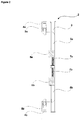
Figure 2 - is a cross sectional view of handle along dashed A-A lines inFigure 1 -
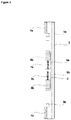
Figure 3 - is a rear view of the handle - The following numerals are assigned to different parts demonstrated in the drawings and referred to in the present detailed description of the invention:
- 1. Door
- 2. Handle
- 3. Canal
- 4. Supports
- 4a. First support
- 4b. Second support
- 5. Tabs
- 5a. First tab
- 5b. Second tab
- 6. Cutouts
- 6a. First cutout
- 6b. Second cutout
- 7. Biasing means
- 7a. First biasing means
- 7b. Second biasing means
- 8. Elements
- 8a. First element
- 8b. Second element
- 9. Slots
- 9a. First slot
- 9b. Second slot
- The present invention relates to a cooling appliance comprising; a body and a door (1) attached to the body between a closed position and an open position; a handle (2), having a canal (3) therein, attached onto an edge of the door (1) by means of a pair of supports (4a,4b) distanced apart from one another on the door (1);
a pair of tabs (5a,5b), configured to slide along the canal (3) between a first position during which the tabs (5a,5b) are inserted inside the supports (4a,4b), fixing the handle (2) onto the door (1) and a second position during which the tabs (5a,5b) come out of the supports (4a,4b), releasing the handle (2) from the door (1). The tabs (5a,5b) are configured to slide along the canal (3) and inside the handle (2). The tabs (5a,5b) slide between a first position during which the tabs (5a,5b) are seated inside the supports (4a,4b), therefore fixing the handle (2) onto the supports (4a,4b). The tabs (5a,5b) slide inside the canal (3) and towards each other, releasing the tabs (5a,5b) from the supports (4a,4b) and therefore the handle (2) from the door (1). The tabs (5a,5b) provides a convenient assembly of the handle (2) onto the door (1). Another advantageous effect provided by means of the tabs (5a,5b) is that the handle (2) can be disassembled during transportation, decreasing the volume of the box and therefore transportation related costs. A further advantageous effect provided by means of the tabs (5a,5b) is that the user can easily assemble and disassemble the handle (2) from the door (1) eliminating the need to call for a maintenance staff. - In another embodiment of the invention, the handle (2) comprises a pair of cutouts (6a,6b) provided on a rear surface accommodating a first end of the pair of tabs (5a,5b). The cutouts (6a,6b) facilitates the sliding movement of the pair of tabs (5a,5b) inside the canal (3).
- In another embodiment of the invention, the handle (2) comprises a pair of biasing means (7a,7b) biasing the tabs (5a,5b) towards the first position. The biasing means (7a,7b) are biasing the tabs (5a,5b) away from each other and towards the supports (4a,4b). The user forces the tabs (5a,5b) towards each other, compressing the biasing means (7a,7b) and releases the tabs (5a,5b) as the tabs (5a,5b) are in close vicinity of the supports (4a,4b). Due to the force created by the biasing means (7a,7b), the tabs (5a,5b) are automatically inserted inside the supports (4a,4b). By means of the biasing means (7a,7b), accidental removal of the tabs (5a,5b) from the supports (4a,4b) is eliminated.
- In another embodiment of the invention, the tabs (5a,5b) comprise an element (8a,8b) protruding outward from the cutouts (6a,6b) having a serrated holding surface. The elements (8a,8b) are used as the means the user forces the tabs (5a,5b) to slide along the canal (3). The serrated surface the elements (8a,8b) provides a strong holding area. Instead of the serrated surface any surface with a patterned structure can be used so as to increase the gripping force.
- In another embodiment of the invention, the pair of supports (4a,4b) comprise a slot (9a,9b) configured to form fittingly accommodate the pair of tabs (5a,5b). The tabs (5a,5b) are seated inside the slots (9a,9b) form fittingly providing a rigid structure and assembly.
- An advantageous effect provided by means of the invention is that the handle (2) can be assembled onto the door (1) in a convenient manner by means of the pair of tabs (5a,5b).
- Another advantageous effect provided by means of the pair of tabs (5a,5b) is that the handle (2) can be easily removed from the door (1).
- Another advantageous effect provided by means of the pair of tabs (5a,5b) is that the handle (2) is rigidly attached onto the door (1), eliminating the possibility of accidental disconnecting of the handle (2) from the door (1), providing safety for the children.
- Another advantageous effect provided by means of handle (2) being easily disassembled from the door (1) provides the handle (2) to be stored inside the cooling appliance during transport, greatly reduces the dimensions of the card board box containing the cooling appliance and therefore the transportation related costs.
Claims (5)
- A cooling appliance comprising;
a body and a door (1) attached to the body between a closed position and an open position;
a handle (2), having a canal (3) therein, attached onto an edge of the door (1) by means of a pair of supports (4a,4b) distanced apart from one another on the door (1);
characterized by
a pair of tabs (5a,5b), configured to slide along the canal (3) between a first position during which the tabs (5a,5b) are inserted inside the supports (4a,4b), fixing the handle (2) onto the door (1) and a second position during which the tabs (5a,5b) come out of the supports (4a,4b), releasing the handle (2) from the door (1). - A cooling appliance according to claim 1, characterized in that the handle (2) comprises a pair of cutouts (6a,6b) provided on a rear surface accommodating a first end of the pair of tabs (5a,5b)
- A cooling appliance according to any preceeding claim , characterized in that the handle (2) comprises a pair of biasing means (7a,7b) biasing the tabs (5a,5b) towards the first position.
- A cooling appliance according to any preceeding claim, characterized in that the tabs (5a,5b) comprise an element (8a,8b) protruding outward from the cutouts (6a,6b) having a serrated holding surface.
- A cooling appliance according to any preceeding claim, characterized in that the pair of supports (4a,4b) comprise a slot (9a,9b) configured to form fittingly accommodate the pair of tabs (5a,5b).
Applications Claiming Priority (1)
| Application Number | Priority Date | Filing Date | Title |
|---|---|---|---|
| TR2020/10220A TR202010220A2 (en) | 2020-06-29 | 2020-06-29 | COOLING DEVICE WITH IMPROVED HANDLE MECHANISM |
Publications (1)
| Publication Number | Publication Date |
|---|---|
| EP3933317A1 true EP3933317A1 (en) | 2022-01-05 |
Family
ID=76180878
Family Applications (1)
| Application Number | Title | Priority Date | Filing Date |
|---|---|---|---|
| EP21176407.1A Withdrawn EP3933317A1 (en) | 2020-06-29 | 2021-05-28 | A cooling appliance having an improved handle mechanism |
Country Status (2)
| Country | Link |
|---|---|
| EP (1) | EP3933317A1 (en) |
| TR (1) | TR202010220A2 (en) |
Citations (8)
| Publication number | Priority date | Publication date | Assignee | Title |
|---|---|---|---|---|
| US3017657A (en) * | 1959-08-19 | 1962-01-23 | Mills Prod Inc | Removable handle assembly for stove doors |
| KR20010061673A (en) * | 1999-12-28 | 2001-07-07 | 구자홍 | Mounting structure of door handle for refrigerator |
| KR20070065743A (en) | 2005-12-20 | 2007-06-25 | 주식회사 대우일렉트로닉스 | Refrigerator door handle fixing structure |
| US20100005631A1 (en) | 2008-07-09 | 2010-01-14 | Whirlpool Corporation | Handle assembly for a domestic appliance |
| KR20100043380A (en) * | 2008-10-20 | 2010-04-29 | 삼성전자주식회사 | Refrigerator |
| US20150115785A1 (en) * | 2013-10-31 | 2015-04-30 | General Electric Company | Appliance and a handle assembly for an appliance |
| WO2015144247A1 (en) | 2014-03-28 | 2015-10-01 | Arcelik Anonim Sirketi | Improved handle assembly for refrigeration appliance door |
| WO2016177428A1 (en) | 2015-05-06 | 2016-11-10 | Arcelik Anonim Sirketi | Door handle-assembly for use in a refrigerator |
-
2020
- 2020-06-29 TR TR2020/10220A patent/TR202010220A2/en unknown
-
2021
- 2021-05-28 EP EP21176407.1A patent/EP3933317A1/en not_active Withdrawn
Patent Citations (8)
| Publication number | Priority date | Publication date | Assignee | Title |
|---|---|---|---|---|
| US3017657A (en) * | 1959-08-19 | 1962-01-23 | Mills Prod Inc | Removable handle assembly for stove doors |
| KR20010061673A (en) * | 1999-12-28 | 2001-07-07 | 구자홍 | Mounting structure of door handle for refrigerator |
| KR20070065743A (en) | 2005-12-20 | 2007-06-25 | 주식회사 대우일렉트로닉스 | Refrigerator door handle fixing structure |
| US20100005631A1 (en) | 2008-07-09 | 2010-01-14 | Whirlpool Corporation | Handle assembly for a domestic appliance |
| KR20100043380A (en) * | 2008-10-20 | 2010-04-29 | 삼성전자주식회사 | Refrigerator |
| US20150115785A1 (en) * | 2013-10-31 | 2015-04-30 | General Electric Company | Appliance and a handle assembly for an appliance |
| WO2015144247A1 (en) | 2014-03-28 | 2015-10-01 | Arcelik Anonim Sirketi | Improved handle assembly for refrigeration appliance door |
| WO2016177428A1 (en) | 2015-05-06 | 2016-11-10 | Arcelik Anonim Sirketi | Door handle-assembly for use in a refrigerator |
Also Published As
| Publication number | Publication date |
|---|---|
| TR202010220A2 (en) | 2022-01-21 |
Similar Documents
| Publication | Publication Date | Title |
|---|---|---|
| US9033294B2 (en) | Release preventing system for wall cupboards | |
| JP6701298B2 (en) | Slide rail assembly | |
| EP2853362B1 (en) | A shaving blade cartridge | |
| US6640442B2 (en) | Cutting stroke-adjustable pruning shears | |
| EP3089852B1 (en) | Device for supporting razor heads | |
| US20080277250A1 (en) | Circuit breaker with improved lock-off accessory | |
| EP0927531A3 (en) | Drawer Cabinet | |
| EP3274762B1 (en) | A quick-release connecting assembly for spectacles | |
| US4837929A (en) | Dry shaver with a readily replaceable outer shearing foil | |
| CN107104366A (en) | Electrical equipment for track installation | |
| EP1975354A1 (en) | Case latch assembly | |
| CN109404384A (en) | Snap component | |
| JP2019532202A (en) | Finger pinching prevention device and its mounting shape | |
| US9924796B2 (en) | Slide rail assembly | |
| EP3933316A1 (en) | A cooling appliance having an improved handle mechanism | |
| EP3030065B1 (en) | Cable management arm supporting device and mounting assembly thereof | |
| EP4024110A1 (en) | Extendable cable enclosure | |
| US11096503B2 (en) | Device for presenting small articles in sales shelf systems | |
| US8690269B2 (en) | Device for fastening a functional unit in a furniture body | |
| KR200476654Y1 (en) | Mirror for bathroom | |
| EP1252070A1 (en) | A locking device and a method for manufacturing thereof | |
| KR100388623B1 (en) | Filing cabinet able to shelf exit and entranced | |
| KR102109012B1 (en) | circuit breaker having bow type joint device | |
| JPH0522096Y2 (en) | ||
| JPH0529Y2 (en) |
Legal Events
| Date | Code | Title | Description |
|---|---|---|---|
| PUAI | Public reference made under article 153(3) epc to a published international application that has entered the european phase |
Free format text: ORIGINAL CODE: 0009012 |
|
| STAA | Information on the status of an ep patent application or granted ep patent |
Free format text: STATUS: REQUEST FOR EXAMINATION WAS MADE |
|
| 17P | Request for examination filed |
Effective date: 20210528 |
|
| AK | Designated contracting states |
Kind code of ref document: A1 Designated state(s): AL AT BE BG CH CY CZ DE DK EE ES FI FR GB GR HR HU IE IS IT LI LT LU LV MC MK MT NL NO PL PT RO RS SE SI SK SM TR |
|
| B565 | Issuance of search results under rule 164(2) epc |
Effective date: 20211108 |
|
| STAA | Information on the status of an ep patent application or granted ep patent |
Free format text: STATUS: THE APPLICATION IS DEEMED TO BE WITHDRAWN |
|
| 18D | Application deemed to be withdrawn |
Effective date: 20220706 |