EP3933296A1 - Refrigeration cycle device - Google Patents
Refrigeration cycle device Download PDFInfo
- Publication number
- EP3933296A1 EP3933296A1 EP19916622.4A EP19916622A EP3933296A1 EP 3933296 A1 EP3933296 A1 EP 3933296A1 EP 19916622 A EP19916622 A EP 19916622A EP 3933296 A1 EP3933296 A1 EP 3933296A1
- Authority
- EP
- European Patent Office
- Prior art keywords
- refrigerant circuit
- compressor
- oil
- time
- controller
- Prior art date
- Legal status (The legal status is an assumption and is not a legal conclusion. Google has not performed a legal analysis and makes no representation as to the accuracy of the status listed.)
- Withdrawn
Links
Images





Classifications
-
- F—MECHANICAL ENGINEERING; LIGHTING; HEATING; WEAPONS; BLASTING
- F25—REFRIGERATION OR COOLING; COMBINED HEATING AND REFRIGERATION SYSTEMS; HEAT PUMP SYSTEMS; MANUFACTURE OR STORAGE OF ICE; LIQUEFACTION SOLIDIFICATION OF GASES
- F25B—REFRIGERATION MACHINES, PLANTS OR SYSTEMS; COMBINED HEATING AND REFRIGERATION SYSTEMS; HEAT PUMP SYSTEMS
- F25B43/00—Arrangements for separating or purifying gases or liquids; Arrangements for vaporising the residuum of liquid refrigerant, e.g. by heat
- F25B43/02—Arrangements for separating or purifying gases or liquids; Arrangements for vaporising the residuum of liquid refrigerant, e.g. by heat for separating lubricants from the refrigerant
-
- F—MECHANICAL ENGINEERING; LIGHTING; HEATING; WEAPONS; BLASTING
- F25—REFRIGERATION OR COOLING; COMBINED HEATING AND REFRIGERATION SYSTEMS; HEAT PUMP SYSTEMS; MANUFACTURE OR STORAGE OF ICE; LIQUEFACTION SOLIDIFICATION OF GASES
- F25B—REFRIGERATION MACHINES, PLANTS OR SYSTEMS; COMBINED HEATING AND REFRIGERATION SYSTEMS; HEAT PUMP SYSTEMS
- F25B9/00—Compression machines, plants or systems, in which the refrigerant is air or other gas of low boiling point
- F25B9/002—Compression machines, plants or systems, in which the refrigerant is air or other gas of low boiling point characterised by the refrigerant
- F25B9/006—Compression machines, plants or systems, in which the refrigerant is air or other gas of low boiling point characterised by the refrigerant the refrigerant containing more than one component
-
- F—MECHANICAL ENGINEERING; LIGHTING; HEATING; WEAPONS; BLASTING
- F25—REFRIGERATION OR COOLING; COMBINED HEATING AND REFRIGERATION SYSTEMS; HEAT PUMP SYSTEMS; MANUFACTURE OR STORAGE OF ICE; LIQUEFACTION SOLIDIFICATION OF GASES
- F25B—REFRIGERATION MACHINES, PLANTS OR SYSTEMS; COMBINED HEATING AND REFRIGERATION SYSTEMS; HEAT PUMP SYSTEMS
- F25B13/00—Compression machines, plants or systems, with reversible cycle
-
- F—MECHANICAL ENGINEERING; LIGHTING; HEATING; WEAPONS; BLASTING
- F25—REFRIGERATION OR COOLING; COMBINED HEATING AND REFRIGERATION SYSTEMS; HEAT PUMP SYSTEMS; MANUFACTURE OR STORAGE OF ICE; LIQUEFACTION SOLIDIFICATION OF GASES
- F25B—REFRIGERATION MACHINES, PLANTS OR SYSTEMS; COMBINED HEATING AND REFRIGERATION SYSTEMS; HEAT PUMP SYSTEMS
- F25B49/00—Arrangement or mounting of control or safety devices
- F25B49/02—Arrangement or mounting of control or safety devices for compression type machines, plants or systems
- F25B49/022—Compressor control arrangements
-
- F—MECHANICAL ENGINEERING; LIGHTING; HEATING; WEAPONS; BLASTING
- F25—REFRIGERATION OR COOLING; COMBINED HEATING AND REFRIGERATION SYSTEMS; HEAT PUMP SYSTEMS; MANUFACTURE OR STORAGE OF ICE; LIQUEFACTION SOLIDIFICATION OF GASES
- F25B—REFRIGERATION MACHINES, PLANTS OR SYSTEMS; COMBINED HEATING AND REFRIGERATION SYSTEMS; HEAT PUMP SYSTEMS
- F25B2500/00—Problems to be solved
- F25B2500/16—Lubrication
-
- F—MECHANICAL ENGINEERING; LIGHTING; HEATING; WEAPONS; BLASTING
- F25—REFRIGERATION OR COOLING; COMBINED HEATING AND REFRIGERATION SYSTEMS; HEAT PUMP SYSTEMS; MANUFACTURE OR STORAGE OF ICE; LIQUEFACTION SOLIDIFICATION OF GASES
- F25B—REFRIGERATION MACHINES, PLANTS OR SYSTEMS; COMBINED HEATING AND REFRIGERATION SYSTEMS; HEAT PUMP SYSTEMS
- F25B2600/00—Control issues
- F25B2600/02—Compressor control
- F25B2600/025—Compressor control by controlling speed
- F25B2600/0253—Compressor control by controlling speed with variable speed
-
- F—MECHANICAL ENGINEERING; LIGHTING; HEATING; WEAPONS; BLASTING
- F25—REFRIGERATION OR COOLING; COMBINED HEATING AND REFRIGERATION SYSTEMS; HEAT PUMP SYSTEMS; MANUFACTURE OR STORAGE OF ICE; LIQUEFACTION SOLIDIFICATION OF GASES
- F25B—REFRIGERATION MACHINES, PLANTS OR SYSTEMS; COMBINED HEATING AND REFRIGERATION SYSTEMS; HEAT PUMP SYSTEMS
- F25B2700/00—Sensing or detecting of parameters; Sensors therefor
- F25B2700/03—Oil level
-
- Y—GENERAL TAGGING OF NEW TECHNOLOGICAL DEVELOPMENTS; GENERAL TAGGING OF CROSS-SECTIONAL TECHNOLOGIES SPANNING OVER SEVERAL SECTIONS OF THE IPC; TECHNICAL SUBJECTS COVERED BY FORMER USPC CROSS-REFERENCE ART COLLECTIONS [XRACs] AND DIGESTS
- Y02—TECHNOLOGIES OR APPLICATIONS FOR MITIGATION OR ADAPTATION AGAINST CLIMATE CHANGE
- Y02B—CLIMATE CHANGE MITIGATION TECHNOLOGIES RELATED TO BUILDINGS, e.g. HOUSING, HOUSE APPLIANCES OR RELATED END-USER APPLICATIONS
- Y02B30/00—Energy efficient heating, ventilation or air conditioning [HVAC]
- Y02B30/70—Efficient control or regulation technologies, e.g. for control of refrigerant flow, motor or heating
Definitions
- the present invention relates to a refrigeration cycle apparatus.
- the refrigeration cycle apparatus described in PTL 1 has a function of determining that the compressor is operated at a low capacity where it is necessary to perform an oil return operation so as to return oil to the compressor and counting the operation time at the low capacity, a function of counting the number of start/stop times of the compressor, and a function of performing an oil return operation when the total operation time of the compressor at the low capacity is longer than a preset total operation time and the number of start/stop times of the compressor is greater than a preset number of start/stop times.
- the preset total operation time and the preset number of start/stop times are constant. Therefore, depending on the state of the refrigeration cycle apparatus, a property of the refrigerant circuit or the like, the oil return operation is performed even when an oil depletion does not occur. As a result, the comfort provided by the refrigeration cycle apparatus and the performance of the refrigeration cycle apparatus may be deteriorated.
- the refrigeration cycle apparatus of the present invention includes a refrigerant circuit.
- the refrigerant circuit includes a compressor, a high-pressure side heat exchanger, a decompressor, and a low-pressure side heat exchanger, which are annularly connected by a refrigerant pipe, and is configured to circulate refrigerant.
- the refrigerant circuit is configured to perform an oil recovery operation based on an operation history of the compressor during a normal operation of the refrigerant circuit and a property of the refrigerant circuit.
- the property of the refrigerant circuit includes at least one selected from the group of a length of the refrigerant pipe, a height difference of the refrigerant pipe, and an outside air temperature.
- the refrigerant circuit performs the oil recovery operation based on an operation history of the compressor during the normal operation of the refrigerant circuit and a property of the refrigerant circuit.
- the oil return operation is performed when the possibility for an oil depletion to occur is high.
- Fig. 1 is a diagram illustrating a configuration of a refrigeration cycle apparatus according to a first embodiment.
- the refrigeration cycle apparatus includes a refrigerant circuit 80 and a controller 5.
- the refrigerant circuit 80 includes a compressor 1, a high-pressure side heat exchanger 2, a decompressor 3, and a low-pressure side heat exchanger 4, which are annularly connected by a refrigerant pipe 81.
- the refrigerant circuit 80 is configured to circulate refrigerant.
- the compressor 1 is configured to allow capacity control.
- the compressor 1 sucks in low pressure refrigerant, compresses the low pressure refrigerant into high pressure refrigerant, and discharges the high pressure refrigerant.
- the high-pressure side heat exchanger 2 functions as a condenser.
- the high-pressure side heat exchanger 2 condenses the high pressure refrigerant compressed by the compressor 1.
- the decompressor 3 depressurizes the high pressure refrigerant condensed by the high-pressure side heat exchanger 2.
- the low-pressure side heat exchanger 4 functions as an evaporator.
- the low-pressure side heat exchanger 4 evaporates the refrigerant depressurized by the decompressor 3.
- the refrigerant circuit 80 is sealed with refrigeration oil.
- the refrigerator oil is simply referred to as oil.
- the refrigerant circuit 80 is controlled to perform either a normal operation or an oil recovery operation.
- the liquid mixture of refrigerant and oil discharged from the compressor 1 flows through the high-pressure side heat exchanger 2, the decompressor 3 and the low-pressure side heat exchanger 4 in this order into the compressor 1.
- the frequency of the compressor 1 decreases for a short time.
- the liquid mixture remains in the high-pressure side heat exchanger 2, the decompressor 3, the low-pressure side heat exchanger 4 and the refrigerant pipe 81, whereby the amount of the liquid mixture flowing into the compressor 1 decreases.
- the liquid mixture in the refrigerant circuit 80 flows according to a pressure difference in the refrigerant circuit 80.
- a total operation time Tt of the compressor 1 during the normal operation of the refrigerant circuit 80 is the sum of the operation time of the compressor 1 during the normal operation of the refrigerant circuit 80.
- the total operation time Tt is the sum of one or more cycle times during the normal operation of the refrigerant circuit 80.
- the number of start/stop times Nt of the compressor 1 during the normal operation of the refrigerant circuit 80 is the sum of the number of start times where the compressor 1 is started and the number of stop times where the compressor 1 is stopped during the normal operation of the refrigerant circuit 80.
- the oil remains in each component of the refrigerant circuit 80.
- the frequency of the compressor 1 is increased greater than the frequency thereof during the normal operation, or the opening degree of the decompressor 3 is increased.
- the oil flows out from each component of the refrigerant circuit 80, and thereby, the amount of oil flowing into the compressor 1 (the oil return amount) increases.
- the controller 5 controls the oil recovery operation of the refrigerant circuit 80 based on an operation history of the compressor 1 during the normal operation of the refrigerant circuit 80 and a property of the refrigerant circuit 80.
- the property of the refrigerant circuit 80 include at least one selected from the group of a length of the refrigerant pipe 81, a height difference of the refrigerant pipe 81, and an outside air temperature.
- the length of the refrigerant pipe 81 refers to the entire length of the refrigerant pipe 81.
- the height difference of the refrigerant pipe 81 refers to a difference between the highest position of the refrigerant pipe 81 and the lowest position of the refrigerant pipe 81.
- the outside air temperature refers to the temperature of air outside the refrigerant circuit 80.
- the controller 5 controls the refrigerant circuit 80 to perform the oil recovery operation when the total operation time Tt of the compressor 1 during the normal operation of the refrigerant circuit 80 is longer than a reference time Tth determined in accordance with a property of the refrigerant circuit 80.
- the controller 5 may set the reference time Tth smaller as the length of the refrigerant pipe 81 becomes longer. Alternatively, the controller 5 may set the reference time Tth to A1 when the length of the refrigerant pipe 81 is equal to or longer than a prescribed length, and set the reference time Tth to B1 when the length of the refrigerant pipe 81 is smaller than the prescribed length (A1 ⁇ B1).
- the controller 5 may set the reference time Tth smaller as the height difference of the refrigerant pipe 81 becomes greater.
- the controller 5 may set the reference time Tth to C1 when the height difference of the refrigerant pipe 81 is equal to or greater than a prescribed value, and set the reference time Tth to D1 when the height difference of the refrigerant pipe 81 is smaller than the prescribed value (C1 ⁇ D1).
- the controller 5 may set the reference time Tth smaller as the outside air temperature becomes lower.
- the controller 5 may set the reference time Tth to E1 when the outside air temperature is equal to or higher than a prescribed temperature, and may set the reference time Tth to F1 when the outside air temperature is lower than the prescribed temperature (E1 > F1).
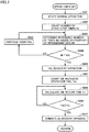
- Fig. 2 is a flowchart illustrating a control process of the refrigeration cycle apparatus according to the first embodiment.
- step S101 the controller 5 starts a normal operation of the refrigerant circuit 80.
- step S102 the controller 5 counts the total operation time Tt of the compressor 1 from the start of the normal operation of the refrigerant circuit 80.
- step S103 the controller 5 calculates the reference time Tth based on a property of the refrigerant circuit 80.
- step S104 if Tt ⁇ Tth, the process proceeds to step S105; and if Tt ⁇ Tth, the process proceeds to step S106.
- step S105 the controller 5 continues counting the total operation time Tt.
- step S106 the controller 5 controls the refrigerant circuit 80 to perform an oil recovery operation.
- the controller 5 increases the number of revolutions of the compressor 1. Accordingly, the amount of oil flowing out from each component of the refrigerant circuit 80 increases, and thereby, the amount of oil flowing into the compressor 1 (the oil return amount) increases.
- step S107 the process is ended.
- the oil recovery operation when the necessity of the oil recovery operation is low (for example, when the refrigerant pipe 81 is short, or the total operation time is small), the oil recovery operation is not performed, which makes it possible to prevent the comfort provided by the refrigeration cycle apparatus from being deteriorated.
- the necessity of the oil recovery operation when the necessity of the oil recovery operation is high (for example, when the length of the refrigerant pipe 81 is long and the total operation time is great), the oil recovery operation is performed, which makes it possible to improve the reliability of the compressor.
- the controller 5 controls the refrigerant circuit 80 to perform an oil recovery operation when the number of start/stop times Nt of the compressor 1 during the normal operation of the refrigerant circuit 80 is greater than a reference number of times Nth determined in accordance with a property of the refrigerant circuit 80.
- the controller 5 may set the reference number of times Nth smaller as the length of the refrigerant pipe 81 becomes longer. Alternatively, the controller 5 may set the reference number of times Nth to A2 when the length of the refrigerant pipe 81 is equal to or longer than a prescribed length, and set the reference number of times Nth to B2 when the length of the refrigerant pipe 81 is smaller than the prescribed length (A2 ⁇ B2).
- the controller 5 may set the reference number of times Nth smaller as the height difference of the refrigerant pipe 81 becomes greater.
- the controller 5 may set the reference number of times Nth to C2 when the height difference of the refrigerant pipe 81 is equal to or greater than a prescribed value, and set the reference number of times Nth to D2 when the height difference of the refrigerant pipe 81 is smaller than the prescribed value (C2 ⁇ D2).
- the controller 5 may set the reference number of times Nth smaller as the outside air temperature becomes lower.
- the controller 5 may set the reference number of times Nth to E2 when the outside air temperature is equal to or higher than a prescribed temperature, and may set the reference number of times Nth to F2 when the outside air temperature is lower than the prescribed temperature (E2 > F2).
- Fig. 3 is a flowchart illustrating a control process of the refrigeration cycle apparatus according to the second embodiment.
- step S601 the controller 5 starts a normal operation of the refrigerant circuit 80.
- step S602 the controller 5 counts the number of start/stop times Nt of the compressor 1 from the start of the normal operation of the refrigerant circuit 80.
- step S603 the controller 5 calculates the reference number of times Nth based on a property of the refrigerant circuit 80.
- step S604 if Nt ⁇ Nth, the process proceeds to step S105; and if Nt ⁇ Nth, the process proceeds to step S106.
- step S605 the controller 5 continues counting the number of start/stop times Nt.
- step S606 the controller 5 controls the refrigerant circuit 80 to perform an oil recovery operation.
- the controller 5 increases the number of revolutions of the compressor 1. Accordingly, the amount of oil flowing out from each component of the refrigerant circuit 80 increases, and thereby, the amount of oil flowing into the compressor 1 (the oil return amount) increases.
- step S607 the process is ended.
- the oil recovery operation when the necessity of the oil recovery operation is low (for example, when the refrigerant pipe 81 is short or the number of start/stop times of the compressor 1 is small), the oil recovery operation is not performed, which makes it possible to prevent the comfort provided by the refrigeration cycle apparatus from being deteriorated.
- the necessity of the oil recovery operation when the necessity of the oil recovery operation is high (for example, when the length of the refrigerant pipe 81 is long and the number of start/stop times of the compressor 1 is great), the oil recovery operation is performed, which makes it possible to improve the reliability of the compressor.
- the controller 5 calculates an oil return time To for the oil discharged from the compressor 1 to return to the compressor 1.
- the controller 5 controls the refrigerant circuit 80 to perform an oil recovery operation when one cycle time Tc from the start to the stop of the compressor 1 is shorter than the oil return time To and the total operation time Tt of the compressor 1 during the normal operation of the refrigerant circuit 80 is longer than the reference time Tth determined in accordance with a property of the refrigerant circuit 80.
- the controller 5 resets the total operation time Tt to 0.
- Fig. 4 is a flowchart illustrating a control process of the refrigeration cycle apparatus according to the third embodiment.
- step S201 the controller 5 starts a normal operation of the refrigerant circuit 80.
- step S202 the controller 5 counts the total operation time Tt of the compressor 1 from the start of the normal operation of the refrigerant circuit 80.
- step S203 the controller 5 calculates the reference time Tth based on a property of the refrigerant circuit 80.
- step S204 If the compressor 1 is started in step S204, the process proceeds to step S205.
- step S205 the controller 5 counts the cycle time Tc.
- step S206 the controller 5 calculates the oil return time To.
- step S207 If the compressor 1 is stopped in step S207, the process proceeds to step S208.
- step S208 if the cycle time Tc is shorter than the oil return time To, the process proceeds to step S210; and if the cycle time Tc is equal to or longer than the oil return time To, the process proceeds to step S209.
- step S209 the controller 5 resets the cycle time Tc to 0.
- step S210 if Tt ⁇ Tth, the process proceeds to step S211; and if Tt ⁇ Tth, the process proceeds to step S212.
- step S211 the controller 5 continues counting the total operation time Tt.
- step S212 the controller 5 controls the refrigerant circuit 80 to perform an oil recovery operation.
- the controller 5 increases the number of revolutions of the compressor 1. Accordingly, the amount of oil flowing out from each component of the refrigerant circuit 80 increases, and thereby, the amount of oil flowing into the compressor 1 (the oil return amount) increases.
- step S213 the process is ended.
- the oil recovery operation when the necessity of the oil recovery operation is low (for example, when the refrigerant pipe 81 is short, the total operation time of the compressor 1 is small, or the cycle time is longer than the oil return time), the oil recovery operation is not performed, which makes it possible to prevent the comfort provided by the refrigeration cycle apparatus from being deteriorated.
- the necessity of the oil recovery operation when the necessity of the oil recovery operation is high (for example, when the length of the refrigerant pipe 81 is long, the total operation time of the compressor 1 is great, and the cycle time is shorter than the oil return time), the oil recovery operation is performed, which makes it possible to improve the reliability of the compressor.
- step S203 the controller 5 determines the reference time Tth based on a property of the refrigerant circuit 80, but it is not limited thereto.
- the controller 5 may set the reference time Tth to a predetermined value irrespective of a property of the refrigerant circuit 80.
- the controller 5 calculates the oil return time To for the oil discharged from the compressor 1 to return to the compressor 1 in the same manner as in the third embodiment.
- the controller 5 controls the refrigerant circuit 80 to perform an oil recovery operation when one cycle time Tc from the start of the compressor 1 to the stop of the compressor 1 is shorter than the oil return time To and the number of start/stop times Nt of the compressor 1 during the normal operation of the refrigerant circuit 80 is greater than the reference number of times Nth determined in accordance with a property of the refrigerant circuit 80.
- the controller 5 resets the number of start/stop times Nt to 0.
- Fig. 5 is a flowchart illustrating a control process of the refrigeration cycle apparatus according to the fourth embodiment.
- step S701 the controller 5 starts a normal operation of the refrigerant circuit 80.
- step S702 the controller 5 counts the number of start/stop times Nt of the compressor 1 from the start of the normal operation of the refrigerant circuit 80.
- step S703 the controller 5 calculates the reference number of times Nth based on a property of the refrigerant circuit 80.
- step S704 If the compressor 1 is started in step S704, the process proceeds to step S705.
- step S705 the controller 5 counts the cycle time Tc.
- step S706 the controller 5 calculates the oil return time To.
- step S707 If the compressor 1 is stopped in step S707, the process proceeds to step S708.
- step S708 if the cycle time Tc is shorter than the oil return time To, the process proceeds to step S710; and if the cycle time Tc is equal to or longer than the oil return time To, the process proceeds to step S709.
- step S709 the controller 5 resets the number of start/stop times Nt to 0.
- step S710 if Nt ⁇ Nth, the process proceeds to step S711; and if Nt ⁇ Nth, the process proceeds to step S712.
- step S711 the controller 5 continues counting the number of start/stop times Nt.
- step S712 the controller 5 controls the refrigerant circuit 80 to perform an oil recovery operation.
- the controller 5 increases the number of revolutions of the compressor 1. Accordingly, the amount of oil flowing out from each component of the refrigerant circuit 80 increases, and thereby, the amount of oil flowing into the compressor 1 (the oil return amount) increases.
- step S713 the process is ended.
- the oil recovery operation when the necessity of the oil recovery operation is low (for example, when the refrigerant pipe 81 is short, the number of start/stop times of the compressor 1 is small, or the cycle time is equal to or longer than the oil return time), the oil recovery operation is not performed, which makes it possible to prevent the comfort provided by the refrigeration cycle apparatus from being deteriorated.
- the necessity of the oil recovery operation when the necessity of the oil recovery operation is high (for example, when the length of the refrigerant pipe 81 is long, the number of start/stop times of the compressor 1 is great and the cycle time is shorter than the oil return time), the oil recovery operation is performed, which makes it possible to improve the reliability of the compressor.
- step S703 the controller 5 determines the reference number of times Nth based on a property of the refrigerant circuit 80, but it is not limited thereto.
- the controller 5 may set the reference number Nth to a predetermined value irrespective of a property of the refrigerant circuit 80.
- the controller 5 calculates the oil return time To for the oil discharged from the compressor 1 to return to the compressor 1 in the same manner as in the third embodiment.
- the controller 5 terminates the oil recovery operation of the refrigerant circuit 80 when an oil recovery operation time is equal to or longer than the oil return time To during the oil recovery operation of the refrigerant circuit 80 according to the first embodiment.
- Fig. 6 is a flowchart illustrating a control process of the refrigeration cycle apparatus according to the fifth embodiment.
- step S301 the controller 5 starts a normal operation of the refrigerant circuit 80.
- step S302 the controller 5 counts the total operation time Tt of the compressor 1 from the start of the normal operation of the refrigerant circuit 80.
- step S303 the controller 5 calculates the reference time Tth based on a property of the refrigerant circuit 80.
- step S304 if Tt ⁇ Tth, the process proceeds to step S305; and if Tt ⁇ Tth, the process proceeds to step S306.
- step S305 the controller 5 continues counting the total operation time Tt.
- step S306 the controller 5 controls the refrigerant circuit 80 to perform an oil recovery operation.
- the controller 5 increases the number of revolutions of the compressor 1. Accordingly, the amount of oil flowing out from each component of the refrigerant circuit 80 increases, and thereby, the amount of oil flowing into the compressor 1 (the oil return amount) increases.
- step S307 the controller 5 counts an oil recovery operation time Tot.
- step S308 the controller 5 calculates the oil return time To.
- step S309 if Tot ⁇ To, the process returns to step S308; and if Tot ⁇ To, the process proceeds to step S310.
- step S310 the controller 5 terminates the oil recovery operation of the refrigerant circuit 80.
- the oil recovery operation may be terminated at an appropriate timing based on the oil return time, which makes it possible to improve the comfort provided by the refrigeration cycle apparatus and the performance of the compressor.
- step S303 the controller 5 determines the reference time Tth based on a property of the refrigerant circuit 80, but it is not limited thereto.
- the controller 5 may set the reference time Tth to a predetermined value irrespective of a property of the refrigerant circuit 80.
- the controller 5 calculates the oil return time To for the oil discharged from the compressor 1 to return to the compressor 1 in the same manner as in the third embodiment.
- the controller 5 terminates the oil recovery operation of the refrigerant circuit 80 when the oil recovery operation time is equal to or longer than the oil return time To during the oil recovery operation of the refrigerant circuit 80 according to the second embodiment.
- Fig. 7 is a flowchart illustrating a control process of a refrigeration cycle apparatus according to a sixth embodiment.
- step S801 the controller 5 starts a normal operation of the refrigerant circuit 80.
- step S802 the controller 5 counts the number of start/stop times Nt of the compressor 1 from the start of the normal operation of the refrigerant circuit 80.
- step S803 the controller 5 calculates the reference number of times Nth based on a property of the refrigerant circuit 80.
- step S804 if Nt ⁇ Nth, the process proceeds to step S805; and if Nt ⁇ Nth, the process proceeds to step S806.
- step S805 the controller 5 continues counting the number of start/stop times Nt.
- step S806 the controller 5 controls the refrigerant circuit 80 to perform an oil recovery operation.
- the controller 5 increases the number of revolutions of the compressor 1. Accordingly, the amount of oil flowing out from each component of the refrigerant circuit 80 increases, and thereby, the amount of oil flowing into the compressor 1 (the oil return amount) increases.
- step S807 the controller 5 counts the oil recovery operation time Tot of the refrigerant circuit 80.
- step S808 the controller 5 calculates the oil return time To.
- step S809 if Tot ⁇ To, the process returns to step S808; and if Tot ⁇ To, the process proceeds to step S810.
- step S810 the controller 5 terminates the oil recovery operation of the refrigerant circuit 80.
- the oil recovery operation may be terminated at an appropriate timing based on the oil return time during the oil recovery operation of the refrigerant circuit 80 according to the second embodiment, which makes it possible to improve the comfort provided by the refrigeration cycle apparatus and the performance of the compressor.
- step S803 the controller 5 determines the reference number of times Nth based on a property of the refrigerant circuit 80, but it is not limited thereto.
- the controller 5 may set the reference number Nth to a predetermined value irrespective of a property of the refrigerant circuit 80.
- the controller 5 controls the refrigerant circuit 80 to perform an oil recovery operation when the total operation time Tt of the compressor 1 during the normal operation of the refrigerant circuit 80 is longer than the reference time Tth determined in accordance with a property of the refrigerant circuit 80 and an amount of oil Om in the compressor 1 is equal to or smaller than a first prescribed value Oth.
- the controller 5 resets the total operation time Tt to 0 when the total operation time Tt of the compressor 1 during the normal operation of the refrigerant circuit 80 is longer than the reference time Tth determined in accordance with a property of the refrigerant circuit 80 and the amount of oil Om in the compressor 1 is greater than the first prescribed value Oth.
- Fig. 8 is a diagram illustrating a configuration of a refrigeration cycle apparatus according to a seventh embodiment.
- the refrigeration cycle apparatus includes an oil depletion sensor 6.
- the oil depletion sensor 6 detects the amount of oil in the compressor 1.
- the oil depletion sensor 6 may be a liquid level sensor or an oil concentration sensor.
- Fig. 9 is a flowchart illustrating a control process of the refrigeration cycle apparatus according to a seventh embodiment.
- step S401 the controller 5 starts a normal operation of the refrigerant circuit 80.
- step S402 the controller 5 detects the amount of oil Om in accordance with a signal from the oil depletion sensor 6.
- step S403 the controller 5 counts the total operation time Tt of the compressor 1 from the start of the normal operation of the refrigerant circuit 80.
- step S404 the controller 5 calculates the reference time Tth based on a property of the refrigerant circuit 80.
- step S405 if Tt ⁇ Tth, the process proceeds to step S406; and if Tt ⁇ Tth, the process proceeds to step S407.
- step S406 the controller 5 continues counting the total operation time Tt.
- step S407 if the amount of oil Om is equal to or smaller than the first prescribed value Oth, the process proceeds to step S409; and if the amount of oil Om is greater than the first prescribed value Oth, the process proceeds to step S408.
- step S408 the controller 5 resets the total operation time Tt to 0.
- step S409 the controller 5 controls the refrigerant circuit 80 to perform an oil recovery operation.
- the controller 5 increases the number of revolutions of the compressor 1. Accordingly, the amount of oil flowing out from each component of the refrigerant circuit 80 increases, and thereby, the amount of oil flowing into the compressor 1 (the oil return amount) increases.
- step S410 when the oil recovery operation of the refrigerant circuit 80 is finished, the process is ended.
- the oil recovery operation when the necessity of the oil recovery operation is low (for example, when the refrigerant pipe 81 is short, the total operation time of the compressor 1 is small, or the amount of oil in the compressor 1 is great), the oil recovery operation is not performed, which makes it possible to prevent the comfort provided by the refrigeration cycle apparatus from being deteriorated.
- the necessity of the oil recovery operation when the necessity of the oil recovery operation is high (for example, when the length of the refrigerant pipe 81 is long, the total operation time of the compressor 1 is great, and the amount of oil in the compressor 1 is small), the oil recovery operation is performed, which makes it possible to improve the reliability of the compressor 1.
- step S404 the controller 5 determines the reference time Tth based on a property of the refrigerant circuit 80, but it is not limited thereto.
- the controller 5 may set the reference time Tth to a predetermined value irrespective of a property of the refrigerant circuit 80.
- the controller 5 controls the refrigerant circuit 80 to perform an oil recovery operation when the number of start/stop times Nt of the compressor 1 during the normal operation of the refrigerant circuit 80 is greater than the reference number of times Nth determined in accordance with a property of the refrigerant circuit 80 and the amount of oil Om in the compressor 1 is equal to or smaller than the first prescribed value Oth.
- the controller 5 resets the number of start/stop times Nt to 0 when the number of start/stop times Nt of the compressor 1 during the normal operation of the refrigerant circuit 80 is greater than the reference number of times Nth determined in accordance with a property of the refrigerant circuit 80 and the amount of oil Om in the compressor 1 is greater than the first prescribed value Oth.
- Fig. 10 is a flowchart illustrating a control process of the refrigeration cycle apparatus according to an eighth embodiment.
- step S901 the controller 5 starts a normal operation of the refrigerant circuit 80.
- step S902 the controller 5 detects the amount of oil Om in accordance with a signal from the oil depletion sensor 6.
- step S903 the controller 5 counts the number of start/stop times Nt of the compressor 1 from the start of the normal operation of the refrigerant circuit 80.
- step S904 the controller 5 calculates the reference number of times Nth based on a property of the refrigerant circuit 80.
- step S905 if Nt ⁇ Nth, the process proceeds to step S906; and if Nt ⁇ Nth, the process proceeds to step S907.
- step S906 the controller 5 continues counting the number of start/stop times Nt.
- step S907 if the amount of oil Om is equal to or smaller than the first prescribed value Oth, the process proceeds to step S909; and if the amount of oil Om is greater the first prescribed value Oth, the process proceeds to step S908.
- step S908 the controller 5 resets the number of start/stop times Nt to 0.
- step S909 the controller 5 controls the refrigerant circuit 80 to perform an oil recovery operation.
- the controller 5 increases the number of revolutions of the compressor 1. Accordingly, the amount of oil flowing out from each component of the refrigerant circuit 80 increases, and thereby, the amount of oil flowing into the compressor 1 (the oil return amount) increases.
- step S910 the process is ended.
- the oil recovery operation when the necessity of the oil recovery operation is low (for example, when the refrigerant pipe 81 is short, the number of start/stop times of the compressor 1 is small, or the amount of oil in the compressor 1 is great), the oil recovery operation is not performed, which makes it possible to prevent the comfort provided by the refrigeration cycle apparatus from being deteriorated.
- the necessity of the oil recovery operation when the necessity of the oil recovery operation is high (for example, when the length of the refrigerant pipe 81 is long, the number of start/stop times of the compressor 1 is great, and the amount of oil in the compressor 1 is small), the oil recovery operation is performed, which makes it possible to improve the reliability of the compressor 1.
- step S904 the controller 5 determines the reference number of times Nth based on a property of the refrigerant circuit 80, but it is not limited thereto.
- the controller 5 may set the reference number Nth to a predetermined value irrespective of a property of the refrigerant circuit 80.
- the controller 5 terminates the oil recovery operation of the refrigerant circuit 80 when the amount of oil Om in the compressor 1 is equal to or greater than the first prescribed value Oth during the oil recovery operation of the refrigerant circuit 80 according to the first embodiment.
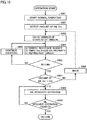
- Fig. 11 is a flowchart illustrating a control process of the refrigeration cycle apparatus according to the ninth embodiment.
- step S501 the controller 5 starts a normal operation of the refrigerant circuit 80.
- step S502 the controller 5 detects the amount of oil Om in accordance with a signal from the oil depletion sensor 6.
- step S503 the controller 5 counts the total operation time Tt of the compressor 1 from the start of the normal operation of the refrigerant circuit 80.
- step S504 the controller 5 calculates the reference time Tth based on a property of the refrigerant circuit 80.
- step S505 if Tt ⁇ Tth, the process proceeds to step S506; and if Tt ⁇ Tth, the process proceeds to step S507.
- step S506 the controller 5 continues counting the total operation time Tt.
- step S507 the controller 5 controls the refrigerant circuit 80 to perform an oil recovery operation.
- the controller 5 increases the number of revolutions of the compressor 1. Accordingly, the amount of oil flowing out from each component of the refrigerant circuit 80 increases, and thereby, the amount of oil flowing into the compressor 1 (the oil return amount) increases.
- step S508 if the amount of oil Om is equal to or greater than the first prescribed value Oth, the process proceeds to step S509; and if the amount of oil Om is smaller than the first prescribed value Oth, the process returns to step S507.
- step S509 the controller 5 terminates the oil recovery operation of the refrigerant circuit 80.
- the oil recovery operation may be terminated at an appropriate timing based on the amount of oil in the compressor detected during the oil recovery operation of the refrigerant circuit 80 according to the first embodiment, which makes it possible to improve the comfort provided by the refrigeration cycle apparatus and the performance of the compressor.
- step S504 the controller 5 determines the reference time Tth based on a property of the refrigerant circuit 80, but it is not limited thereto.
- the controller 5 may set the reference time Tth to a predetermined value irrespective of a property of the refrigerant circuit 80.
- the controller 5 terminates the oil recovery operation of the refrigerant circuit 80 when the amount of oil Om in the compressor 1 is equal to or greater than the first prescribed value Oth during the oil recovery operation of the refrigerant circuit 80 according to the second embodiment.
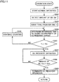
- Fig. 12 is a flowchart illustrating a control process of the refrigeration cycle apparatus according to a tenth embodiment.
- step S1001 the controller 5 starts a normal operation of the refrigerant circuit 80.
- step S1002 the controller 5 detects the amount of oil Om in accordance with the signal from the oil depletion sensor 6.
- step S1003 the controller 5 counts the number of start/stop times Nt of the compressor 1 from the start of the normal operation of the refrigerant circuit 80.
- step S1004 the controller 5 calculates the reference number of times Nth based on a property of the refrigerant circuit 80.
- step S1005 if Nt ⁇ Nth, the process proceeds to step S1006; and if Nt ⁇ Nth, the process proceeds to step S1007.
- step S1006 the controller 5 continues counting the number of start/stop times Nt.
- step S1007 the controller 5 controls the refrigerant circuit 80 to perform an oil recovery operation.
- the controller 5 increases the number of revolutions of the compressor 1. Accordingly, the amount of oil flowing out from each component of the refrigerant circuit 80 increases, and thereby, the amount of oil flowing into the compressor 1 (the oil return amount) increases.
- step S1008 If the amount of oil Om is equal to or greater than the first prescribed value Oth in step S1008, the process proceeds to step S1009; and if the amount of oil Om is smaller than the first prescribed value Oth, the process returns to step S1007.
- step S1009 the controller 5 terminates the oil recovery operation of the refrigerant circuit 80.
- the oil recovery operation may be terminated at an appropriate timing based on the amount of oil in the compressor detected during the oil recovery operation of the refrigerant circuit 80 according to the second embodiment, which makes it possible to improve the comfort provided by the refrigeration cycle apparatus and the performance of the compressor.
- step S1004 the controller 5 determines the reference number of times Nth based on a property of the refrigerant circuit 80, but it is not limited thereto.
- the controller 5 may set the reference number Nth to a predetermined value irrespective of a property of the refrigerant circuit 80.
Landscapes
- Engineering & Computer Science (AREA)
- Physics & Mathematics (AREA)
- Mechanical Engineering (AREA)
- Thermal Sciences (AREA)
- General Engineering & Computer Science (AREA)
- Chemical & Material Sciences (AREA)
- Analytical Chemistry (AREA)
- Power Engineering (AREA)
- Air Conditioning Control Device (AREA)
Abstract
Description
- The present invention relates to a refrigeration cycle apparatus.
- There is known a refrigeration cycle apparatus having a function of performing an oil return operation so as to return lubricating oil to a compressor. For example, the refrigeration cycle apparatus described in
PTL 1 has a function of determining that the compressor is operated at a low capacity where it is necessary to perform an oil return operation so as to return oil to the compressor and counting the operation time at the low capacity, a function of counting the number of start/stop times of the compressor, and a function of performing an oil return operation when the total operation time of the compressor at the low capacity is longer than a preset total operation time and the number of start/stop times of the compressor is greater than a preset number of start/stop times. - PTL 1:
Japanese Patent Laying-Open No. 2016-194389 - However, in the refrigeration cycle apparatus described in
PTL 1, the preset total operation time and the preset number of start/stop times are constant. Therefore, depending on the state of the refrigeration cycle apparatus, a property of the refrigerant circuit or the like, the oil return operation is performed even when an oil depletion does not occur. As a result, the comfort provided by the refrigeration cycle apparatus and the performance of the refrigeration cycle apparatus may be deteriorated. - Therefore, it is an object of the present invention to provide a refrigeration cycle apparatus which performs an oil return operation when the possibility for an oil depletion to occur is high.
- The refrigeration cycle apparatus of the present invention includes a refrigerant circuit. The refrigerant circuit includes a compressor, a high-pressure side heat exchanger, a decompressor, and a low-pressure side heat exchanger, which are annularly connected by a refrigerant pipe, and is configured to circulate refrigerant. The refrigerant circuit is configured to perform an oil recovery operation based on an operation history of the compressor during a normal operation of the refrigerant circuit and a property of the refrigerant circuit. The property of the refrigerant circuit includes at least one selected from the group of a length of the refrigerant pipe, a height difference of the refrigerant pipe, and an outside air temperature.
- According to the present invention, the refrigerant circuit performs the oil recovery operation based on an operation history of the compressor during the normal operation of the refrigerant circuit and a property of the refrigerant circuit. Thus, the oil return operation is performed when the possibility for an oil depletion to occur is high.
-
-
Fig. 1 is a diagram illustrating a configuration of a refrigeration cycle apparatus according to a first embodiment; -
Fig. 2 is a flowchart illustrating a control process of the refrigeration cycle apparatus according to the first embodiment; -
Fig. 3 is a flowchart illustrating a control process of a refrigeration cycle apparatus according to a second embodiment; -
Fig. 4 is a flowchart illustrating a control process of a refrigeration cycle apparatus according to a third embodiment; -
Fig. 5 is a flowchart illustrating a control process of a refrigeration cycle apparatus according to a fourth embodiment; -
Fig. 6 is a flowchart illustrating a control process of a refrigeration cycle apparatus according to a fifth embodiment; -
Fig. 7 is a flowchart illustrating a control process of a refrigeration cycle apparatus according to a sixth embodiment; -
Fig. 8 is a diagram illustrating a configuration of a refrigeration cycle apparatus according to a seventh embodiment; -
Fig. 9 is a flowchart illustrating a control process of the refrigeration cycle apparatus according to the seventh embodiment; -
Fig. 10 is a flowchart illustrating a control process of a refrigeration cycle apparatus according to an eighth embodiment; -
Fig. 11 is a flowchart illustrating a control process of a refrigeration cycle apparatus according to a ninth embodiment; and -
Fig. 12 is a flowchart illustrating a control process of a refrigeration cycle apparatus according to a tenth embodiment. - Hereinafter, embodiments will be described with reference to the drawings.
-
Fig. 1 is a diagram illustrating a configuration of a refrigeration cycle apparatus according to a first embodiment. - The refrigeration cycle apparatus includes a
refrigerant circuit 80 and acontroller 5. - The
refrigerant circuit 80 includes acompressor 1, a high-pressureside heat exchanger 2, adecompressor 3, and a low-pressureside heat exchanger 4, which are annularly connected by arefrigerant pipe 81. - The
refrigerant circuit 80 is configured to circulate refrigerant. Thecompressor 1 is configured to allow capacity control. Thecompressor 1 sucks in low pressure refrigerant, compresses the low pressure refrigerant into high pressure refrigerant, and discharges the high pressure refrigerant. The high-pressureside heat exchanger 2 functions as a condenser. The high-pressureside heat exchanger 2 condenses the high pressure refrigerant compressed by thecompressor 1. Thedecompressor 3 depressurizes the high pressure refrigerant condensed by the high-pressureside heat exchanger 2. The low-pressureside heat exchanger 4 functions as an evaporator. The low-pressureside heat exchanger 4 evaporates the refrigerant depressurized by thedecompressor 3. - The
refrigerant circuit 80 is sealed with refrigeration oil. In the following description, the refrigerator oil is simply referred to as oil. Therefrigerant circuit 80 is controlled to perform either a normal operation or an oil recovery operation. - The liquid mixture of refrigerant and oil discharged from the
compressor 1 flows through the high-pressureside heat exchanger 2, thedecompressor 3 and the low-pressureside heat exchanger 4 in this order into thecompressor 1. In the normal operation, since the amount of the liquid mixture discharged from thecompressor 1 increases abruptly at the start of thecompressor 1, the frequency of thecompressor 1 decreases for a short time. As a result, the liquid mixture remains in the high-pressureside heat exchanger 2, thedecompressor 3, the low-pressureside heat exchanger 4 and therefrigerant pipe 81, whereby the amount of the liquid mixture flowing into thecompressor 1 decreases. After thecompressor 1 is finally stopped, the liquid mixture in therefrigerant circuit 80 flows according to a pressure difference in therefrigerant circuit 80. Therefore, during the normal operation, in one cycle from the start to the stop of thecompressor 1, although the outflow amount of oil from thecompressor 1 increases, the inflow amount (the oil return amount) decreases. As thecompressor 1 performs such intermittent operation repeatedly, the amount of oil in thecompressor 1 will decrease. During the normal operation of therefrigerant circuit 80, thecompressor 1 is repeatedly started and stopped. A total operation time Tt of thecompressor 1 during the normal operation of therefrigerant circuit 80 is the sum of the operation time of thecompressor 1 during the normal operation of therefrigerant circuit 80. When the time from the start to the stop of thecompressor 1 is defined as a cycle time, the total operation time Tt is the sum of one or more cycle times during the normal operation of therefrigerant circuit 80. The number of start/stop times Nt of thecompressor 1 during the normal operation of therefrigerant circuit 80 is the sum of the number of start times where thecompressor 1 is started and the number of stop times where thecompressor 1 is stopped during the normal operation of therefrigerant circuit 80. - During the normal operation, the oil remains in each component of the
refrigerant circuit 80. In an oil recovery operation, for example, the frequency of thecompressor 1 is increased greater than the frequency thereof during the normal operation, or the opening degree of thedecompressor 3 is increased. As a result, the oil flows out from each component of therefrigerant circuit 80, and thereby, the amount of oil flowing into the compressor 1 (the oil return amount) increases. - The
controller 5 controls the oil recovery operation of therefrigerant circuit 80 based on an operation history of thecompressor 1 during the normal operation of therefrigerant circuit 80 and a property of therefrigerant circuit 80. - The property of the
refrigerant circuit 80 include at least one selected from the group of a length of therefrigerant pipe 81, a height difference of therefrigerant pipe 81, and an outside air temperature. The length of therefrigerant pipe 81 refers to the entire length of therefrigerant pipe 81. The height difference of therefrigerant pipe 81 refers to a difference between the highest position of therefrigerant pipe 81 and the lowest position of therefrigerant pipe 81. The outside air temperature refers to the temperature of air outside therefrigerant circuit 80. - Specifically, in the present embodiment, the
controller 5 controls therefrigerant circuit 80 to perform the oil recovery operation when the total operation time Tt of thecompressor 1 during the normal operation of therefrigerant circuit 80 is longer than a reference time Tth determined in accordance with a property of therefrigerant circuit 80. - The
controller 5 may set the reference time Tth smaller as the length of therefrigerant pipe 81 becomes longer. Alternatively, thecontroller 5 may set the reference time Tth to A1 when the length of therefrigerant pipe 81 is equal to or longer than a prescribed length, and set the reference time Tth to B1 when the length of therefrigerant pipe 81 is smaller than the prescribed length (A1 < B1). - Alternatively, the
controller 5 may set the reference time Tth smaller as the height difference of therefrigerant pipe 81 becomes greater. Alternatively, thecontroller 5 may set the reference time Tth to C1 when the height difference of therefrigerant pipe 81 is equal to or greater than a prescribed value, and set the reference time Tth to D1 when the height difference of therefrigerant pipe 81 is smaller than the prescribed value (C1 < D1). - Alternatively, the
controller 5 may set the reference time Tth smaller as the outside air temperature becomes lower. Alternatively, thecontroller 5 may set the reference time Tth to E1 when the outside air temperature is equal to or higher than a prescribed temperature, and may set the reference time Tth to F1 when the outside air temperature is lower than the prescribed temperature (E1 > F1). -
Fig. 2 is a flowchart illustrating a control process of the refrigeration cycle apparatus according to the first embodiment. - In step S101, the
controller 5 starts a normal operation of therefrigerant circuit 80. - In step S102, the
controller 5 counts the total operation time Tt of thecompressor 1 from the start of the normal operation of therefrigerant circuit 80. - In step S103, the
controller 5 calculates the reference time Tth based on a property of therefrigerant circuit 80. - In step S104, if Tt < Tth, the process proceeds to step S105; and if Tt ≥ Tth, the process proceeds to step S106.
- In step S105, the
controller 5 continues counting the total operation time Tt. - In step S106, the
controller 5 controls therefrigerant circuit 80 to perform an oil recovery operation. In the oil recovery operation, for example, thecontroller 5 increases the number of revolutions of thecompressor 1. Accordingly, the amount of oil flowing out from each component of therefrigerant circuit 80 increases, and thereby, the amount of oil flowing into the compressor 1 (the oil return amount) increases. - When the oil recovery operation of the
refrigerant circuit 80 is finished in step S107, the process is ended. - As described above, according to the present embodiment, when the necessity of the oil recovery operation is low (for example, when the
refrigerant pipe 81 is short, or the total operation time is small), the oil recovery operation is not performed, which makes it possible to prevent the comfort provided by the refrigeration cycle apparatus from being deteriorated. According to the present embodiment, when the necessity of the oil recovery operation is high (for example, when the length of therefrigerant pipe 81 is long and the total operation time is great), the oil recovery operation is performed, which makes it possible to improve the reliability of the compressor. - Specifically, in the present embodiment, the
controller 5 controls therefrigerant circuit 80 to perform an oil recovery operation when the number of start/stop times Nt of thecompressor 1 during the normal operation of therefrigerant circuit 80 is greater than a reference number of times Nth determined in accordance with a property of therefrigerant circuit 80. - The
controller 5 may set the reference number of times Nth smaller as the length of therefrigerant pipe 81 becomes longer. Alternatively, thecontroller 5 may set the reference number of times Nth to A2 when the length of therefrigerant pipe 81 is equal to or longer than a prescribed length, and set the reference number of times Nth to B2 when the length of therefrigerant pipe 81 is smaller than the prescribed length (A2 < B2). - Alternatively, the
controller 5 may set the reference number of times Nth smaller as the height difference of therefrigerant pipe 81 becomes greater. Alternatively, thecontroller 5 may set the reference number of times Nth to C2 when the height difference of therefrigerant pipe 81 is equal to or greater than a prescribed value, and set the reference number of times Nth to D2 when the height difference of therefrigerant pipe 81 is smaller than the prescribed value (C2 < D2). - Alternatively, the
controller 5 may set the reference number of times Nth smaller as the outside air temperature becomes lower. Alternatively, thecontroller 5 may set the reference number of times Nth to E2 when the outside air temperature is equal to or higher than a prescribed temperature, and may set the reference number of times Nth to F2 when the outside air temperature is lower than the prescribed temperature (E2 > F2). -
Fig. 3 is a flowchart illustrating a control process of the refrigeration cycle apparatus according to the second embodiment. - In step S601, the
controller 5 starts a normal operation of therefrigerant circuit 80. - In step S602, the
controller 5 counts the number of start/stop times Nt of thecompressor 1 from the start of the normal operation of therefrigerant circuit 80. - In step S603, the
controller 5 calculates the reference number of times Nth based on a property of therefrigerant circuit 80. - In step S604, if Nt < Nth, the process proceeds to step S105; and if Nt ≥ Nth, the process proceeds to step S106.
- In step S605, the
controller 5 continues counting the number of start/stop times Nt. - In step S606, the
controller 5 controls therefrigerant circuit 80 to perform an oil recovery operation. In the oil recovery operation, for example, thecontroller 5 increases the number of revolutions of thecompressor 1. Accordingly, the amount of oil flowing out from each component of therefrigerant circuit 80 increases, and thereby, the amount of oil flowing into the compressor 1 (the oil return amount) increases. - When the oil recovery operation of the
refrigerant circuit 80 is finished in step S607, the process is ended. - As described above, according to the present embodiment, when the necessity of the oil recovery operation is low (for example, when the
refrigerant pipe 81 is short or the number of start/stop times of thecompressor 1 is small), the oil recovery operation is not performed, which makes it possible to prevent the comfort provided by the refrigeration cycle apparatus from being deteriorated. According to the present embodiment, when the necessity of the oil recovery operation is high (for example, when the length of therefrigerant pipe 81 is long and the number of start/stop times of thecompressor 1 is great), the oil recovery operation is performed, which makes it possible to improve the reliability of the compressor. - In the present embodiment, the
controller 5 calculates an oil return time To for the oil discharged from thecompressor 1 to return to thecompressor 1. - For example, the
controller 5 calculates the oil return time To according to the following formula:

compressor 1, Vst represents a stroke volume of thecompressor 1, ps represents a density of the sucted refrigerant, ϕ represents an oil circulation rate, and Lt represents a total length of therefrigerant pipe 81. - The
controller 5 controls therefrigerant circuit 80 to perform an oil recovery operation when one cycle time Tc from the start to the stop of thecompressor 1 is shorter than the oil return time To and the total operation time Tt of thecompressor 1 during the normal operation of therefrigerant circuit 80 is longer than the reference time Tth determined in accordance with a property of therefrigerant circuit 80. When one cycle time Tc is equal to or longer than the oil return time To, thecontroller 5 resets the total operation time Tt to 0. -
Fig. 4 is a flowchart illustrating a control process of the refrigeration cycle apparatus according to the third embodiment. - In step S201, the
controller 5 starts a normal operation of therefrigerant circuit 80. - In step S202, the
controller 5 counts the total operation time Tt of thecompressor 1 from the start of the normal operation of therefrigerant circuit 80. - In step S203, the
controller 5 calculates the reference time Tth based on a property of therefrigerant circuit 80. - If the
compressor 1 is started in step S204, the process proceeds to step S205. - In step S205, the
controller 5 counts the cycle time Tc. - In step S206, the
controller 5 calculates the oil return time To. - If the
compressor 1 is stopped in step S207, the process proceeds to step S208. - In step S208, if the cycle time Tc is shorter than the oil return time To, the process proceeds to step S210; and if the cycle time Tc is equal to or longer than the oil return time To, the process proceeds to step S209.
- In step S209, the
controller 5 resets the cycle time Tc to 0. - In step S210, if Tt < Tth, the process proceeds to step S211; and if Tt ≥ Tth, the process proceeds to step S212.
- In step S211, the
controller 5 continues counting the total operation time Tt. - In step S212, the
controller 5 controls therefrigerant circuit 80 to perform an oil recovery operation. In the oil recovery operation, for example, thecontroller 5 increases the number of revolutions of thecompressor 1. Accordingly, the amount of oil flowing out from each component of therefrigerant circuit 80 increases, and thereby, the amount of oil flowing into the compressor 1 (the oil return amount) increases. - When the oil recovery operation of the
refrigerant circuit 80 is finished in step S213, the process is ended. - As described above, according to the present embodiment, when the necessity of the oil recovery operation is low (for example, when the
refrigerant pipe 81 is short, the total operation time of thecompressor 1 is small, or the cycle time is longer than the oil return time), the oil recovery operation is not performed, which makes it possible to prevent the comfort provided by the refrigeration cycle apparatus from being deteriorated. According to the present embodiment, when the necessity of the oil recovery operation is high (for example, when the length of therefrigerant pipe 81 is long, the total operation time of thecompressor 1 is great, and the cycle time is shorter than the oil return time), the oil recovery operation is performed, which makes it possible to improve the reliability of the compressor. - In the above embodiment, in step S203, the
controller 5 determines the reference time Tth based on a property of therefrigerant circuit 80, but it is not limited thereto. Thecontroller 5 may set the reference time Tth to a predetermined value irrespective of a property of therefrigerant circuit 80. - In the present embodiment, the
controller 5 calculates the oil return time To for the oil discharged from thecompressor 1 to return to thecompressor 1 in the same manner as in the third embodiment. - In the present embodiment, the
controller 5 controls therefrigerant circuit 80 to perform an oil recovery operation when one cycle time Tc from the start of thecompressor 1 to the stop of thecompressor 1 is shorter than the oil return time To and the number of start/stop times Nt of thecompressor 1 during the normal operation of therefrigerant circuit 80 is greater than the reference number of times Nth determined in accordance with a property of therefrigerant circuit 80. When one cycle time Tc is equal to or longer than the oil return time To, thecontroller 5 resets the number of start/stop times Nt to 0. -
Fig. 5 is a flowchart illustrating a control process of the refrigeration cycle apparatus according to the fourth embodiment. - In step S701, the
controller 5 starts a normal operation of therefrigerant circuit 80. - In step S702, the
controller 5 counts the number of start/stop times Nt of thecompressor 1 from the start of the normal operation of therefrigerant circuit 80. - In step S703, the
controller 5 calculates the reference number of times Nth based on a property of therefrigerant circuit 80. - If the
compressor 1 is started in step S704, the process proceeds to step S705. - In step S705, the
controller 5 counts the cycle time Tc. - In step S706, the
controller 5 calculates the oil return time To. - If the
compressor 1 is stopped in step S707, the process proceeds to step S708. - In step S708, if the cycle time Tc is shorter than the oil return time To, the process proceeds to step S710; and if the cycle time Tc is equal to or longer than the oil return time To, the process proceeds to step S709.
- In step S709, the
controller 5 resets the number of start/stop times Nt to 0. - In step S710, if Nt < Nth, the process proceeds to step S711; and if Nt ≥ Nth, the process proceeds to step S712.
- In step S711, the
controller 5 continues counting the number of start/stop times Nt. - In step S712, the
controller 5 controls therefrigerant circuit 80 to perform an oil recovery operation. In the oil recovery operation, for example, thecontroller 5 increases the number of revolutions of thecompressor 1. Accordingly, the amount of oil flowing out from each component of therefrigerant circuit 80 increases, and thereby, the amount of oil flowing into the compressor 1 (the oil return amount) increases. - When the oil recovery operation of the
refrigerant circuit 80 is finished in step S713, the process is ended. - As described above, according to the present embodiment, when the necessity of the oil recovery operation is low (for example, when the
refrigerant pipe 81 is short, the number of start/stop times of thecompressor 1 is small, or the cycle time is equal to or longer than the oil return time), the oil recovery operation is not performed, which makes it possible to prevent the comfort provided by the refrigeration cycle apparatus from being deteriorated. According to the present embodiment, when the necessity of the oil recovery operation is high (for example, when the length of therefrigerant pipe 81 is long, the number of start/stop times of thecompressor 1 is great and the cycle time is shorter than the oil return time), the oil recovery operation is performed, which makes it possible to improve the reliability of the compressor. - In the above embodiment, in step S703, the
controller 5 determines the reference number of times Nth based on a property of therefrigerant circuit 80, but it is not limited thereto. Thecontroller 5 may set the reference number Nth to a predetermined value irrespective of a property of therefrigerant circuit 80. - In the present embodiment, the
controller 5 calculates the oil return time To for the oil discharged from thecompressor 1 to return to thecompressor 1 in the same manner as in the third embodiment. - In the present embodiment, the
controller 5 terminates the oil recovery operation of therefrigerant circuit 80 when an oil recovery operation time is equal to or longer than the oil return time To during the oil recovery operation of therefrigerant circuit 80 according to the first embodiment. -
Fig. 6 is a flowchart illustrating a control process of the refrigeration cycle apparatus according to the fifth embodiment. - In step S301, the
controller 5 starts a normal operation of therefrigerant circuit 80. - In step S302, the
controller 5 counts the total operation time Tt of thecompressor 1 from the start of the normal operation of therefrigerant circuit 80. - In step S303, the
controller 5 calculates the reference time Tth based on a property of therefrigerant circuit 80. - In step S304, if Tt < Tth, the process proceeds to step S305; and if Tt ≥ Tth, the process proceeds to step S306.
- In step S305, the
controller 5 continues counting the total operation time Tt. - In step S306, the
controller 5 controls therefrigerant circuit 80 to perform an oil recovery operation. In the oil recovery operation, for example, thecontroller 5 increases the number of revolutions of thecompressor 1. Accordingly, the amount of oil flowing out from each component of therefrigerant circuit 80 increases, and thereby, the amount of oil flowing into the compressor 1 (the oil return amount) increases. - In step S307, the
controller 5 counts an oil recovery operation time Tot. - In step S308, the
controller 5 calculates the oil return time To. - In step S309, if Tot < To, the process returns to step S308; and if Tot ≥ To, the process proceeds to step S310.
- In step S310, the
controller 5 terminates the oil recovery operation of therefrigerant circuit 80. - As described above, according to the present embodiment, during the oil recovery operation of the
refrigerant circuit 80 according the first embodiment, the oil recovery operation may be terminated at an appropriate timing based on the oil return time, which makes it possible to improve the comfort provided by the refrigeration cycle apparatus and the performance of the compressor. - In the above embodiment, in step S303, the
controller 5 determines the reference time Tth based on a property of therefrigerant circuit 80, but it is not limited thereto. Thecontroller 5 may set the reference time Tth to a predetermined value irrespective of a property of therefrigerant circuit 80. - In the present embodiment, the
controller 5 calculates the oil return time To for the oil discharged from thecompressor 1 to return to thecompressor 1 in the same manner as in the third embodiment. - In the present embodiment, the
controller 5 terminates the oil recovery operation of therefrigerant circuit 80 when the oil recovery operation time is equal to or longer than the oil return time To during the oil recovery operation of therefrigerant circuit 80 according to the second embodiment. -
Fig. 7 is a flowchart illustrating a control process of a refrigeration cycle apparatus according to a sixth embodiment. - In step S801, the
controller 5 starts a normal operation of therefrigerant circuit 80. - In step S802, the
controller 5 counts the number of start/stop times Nt of thecompressor 1 from the start of the normal operation of therefrigerant circuit 80. - In step S803, the
controller 5 calculates the reference number of times Nth based on a property of therefrigerant circuit 80. - In step S804, if Nt < Nth, the process proceeds to step S805; and if Nt ≥ Nth, the process proceeds to step S806.
- In step S805, the
controller 5 continues counting the number of start/stop times Nt. - In step S806, the
controller 5 controls therefrigerant circuit 80 to perform an oil recovery operation. In the oil recovery operation, for example, thecontroller 5 increases the number of revolutions of thecompressor 1. Accordingly, the amount of oil flowing out from each component of therefrigerant circuit 80 increases, and thereby, the amount of oil flowing into the compressor 1 (the oil return amount) increases. - In step S807, the
controller 5 counts the oil recovery operation time Tot of therefrigerant circuit 80. - In step S808, the
controller 5 calculates the oil return time To. - In step S809, if Tot < To, the process returns to step S808; and if Tot ≥ To, the process proceeds to step S810.
- In step S810, the
controller 5 terminates the oil recovery operation of therefrigerant circuit 80. - As described above, according to the present embodiment, the oil recovery operation may be terminated at an appropriate timing based on the oil return time during the oil recovery operation of the
refrigerant circuit 80 according to the second embodiment, which makes it possible to improve the comfort provided by the refrigeration cycle apparatus and the performance of the compressor. - In the above embodiment, in step S803, the
controller 5 determines the reference number of times Nth based on a property of therefrigerant circuit 80, but it is not limited thereto. Thecontroller 5 may set the reference number Nth to a predetermined value irrespective of a property of therefrigerant circuit 80. - In the present embodiment, the
controller 5 controls therefrigerant circuit 80 to perform an oil recovery operation when the total operation time Tt of thecompressor 1 during the normal operation of therefrigerant circuit 80 is longer than the reference time Tth determined in accordance with a property of therefrigerant circuit 80 and an amount of oil Om in thecompressor 1 is equal to or smaller than a first prescribed value Oth. - The
controller 5 resets the total operation time Tt to 0 when the total operation time Tt of thecompressor 1 during the normal operation of therefrigerant circuit 80 is longer than the reference time Tth determined in accordance with a property of therefrigerant circuit 80 and the amount of oil Om in thecompressor 1 is greater than the first prescribed value Oth. -
Fig. 8 is a diagram illustrating a configuration of a refrigeration cycle apparatus according to a seventh embodiment. - The refrigeration cycle apparatus includes an
oil depletion sensor 6. Theoil depletion sensor 6 detects the amount of oil in thecompressor 1. Theoil depletion sensor 6 may be a liquid level sensor or an oil concentration sensor. -
Fig. 9 is a flowchart illustrating a control process of the refrigeration cycle apparatus according to a seventh embodiment. - In step S401, the
controller 5 starts a normal operation of therefrigerant circuit 80. - In step S402, the
controller 5 detects the amount of oil Om in accordance with a signal from theoil depletion sensor 6. - In step S403, the
controller 5 counts the total operation time Tt of thecompressor 1 from the start of the normal operation of therefrigerant circuit 80. - In step S404, the
controller 5 calculates the reference time Tth based on a property of therefrigerant circuit 80. - In step S405, if Tt < Tth, the process proceeds to step S406; and if Tt ≥ Tth, the process proceeds to step S407.
- In step S406, the
controller 5 continues counting the total operation time Tt. - In step S407, if the amount of oil Om is equal to or smaller than the first prescribed value Oth, the process proceeds to step S409; and if the amount of oil Om is greater than the first prescribed value Oth, the process proceeds to step S408.
- In step S408, the
controller 5 resets the total operation time Tt to 0. - In step S409, the
controller 5 controls therefrigerant circuit 80 to perform an oil recovery operation. In the oil recovery operation, for example, thecontroller 5 increases the number of revolutions of thecompressor 1. Accordingly, the amount of oil flowing out from each component of therefrigerant circuit 80 increases, and thereby, the amount of oil flowing into the compressor 1 (the oil return amount) increases. - In step S410, when the oil recovery operation of the
refrigerant circuit 80 is finished, the process is ended. - As described above, according to the present embodiment, when the necessity of the oil recovery operation is low (for example, when the
refrigerant pipe 81 is short, the total operation time of thecompressor 1 is small, or the amount of oil in thecompressor 1 is great), the oil recovery operation is not performed, which makes it possible to prevent the comfort provided by the refrigeration cycle apparatus from being deteriorated. According to the present embodiment, when the necessity of the oil recovery operation is high (for example, when the length of therefrigerant pipe 81 is long, the total operation time of thecompressor 1 is great, and the amount of oil in thecompressor 1 is small), the oil recovery operation is performed, which makes it possible to improve the reliability of thecompressor 1. - In the above embodiment, in step S404, the
controller 5 determines the reference time Tth based on a property of therefrigerant circuit 80, but it is not limited thereto. Thecontroller 5 may set the reference time Tth to a predetermined value irrespective of a property of therefrigerant circuit 80. - In the present embodiment, the
controller 5 controls therefrigerant circuit 80 to perform an oil recovery operation when the number of start/stop times Nt of thecompressor 1 during the normal operation of therefrigerant circuit 80 is greater than the reference number of times Nth determined in accordance with a property of therefrigerant circuit 80 and the amount of oil Om in thecompressor 1 is equal to or smaller than the first prescribed value Oth. - The
controller 5 resets the number of start/stop times Nt to 0 when the number of start/stop times Nt of thecompressor 1 during the normal operation of therefrigerant circuit 80 is greater than the reference number of times Nth determined in accordance with a property of therefrigerant circuit 80 and the amount of oil Om in thecompressor 1 is greater than the first prescribed value Oth. -
Fig. 10 is a flowchart illustrating a control process of the refrigeration cycle apparatus according to an eighth embodiment. - In step S901, the
controller 5 starts a normal operation of therefrigerant circuit 80. - In step S902, the
controller 5 detects the amount of oil Om in accordance with a signal from theoil depletion sensor 6. - In step S903, the
controller 5 counts the number of start/stop times Nt of thecompressor 1 from the start of the normal operation of therefrigerant circuit 80. - In step S904, the
controller 5 calculates the reference number of times Nth based on a property of therefrigerant circuit 80. - In step S905, if Nt < Nth, the process proceeds to step S906; and if Nt ≥ Nth, the process proceeds to step S907.
- In step S906, the
controller 5 continues counting the number of start/stop times Nt. - In step S907, if the amount of oil Om is equal to or smaller than the first prescribed value Oth, the process proceeds to step S909; and if the amount of oil Om is greater the first prescribed value Oth, the process proceeds to step S908.
- In step S908, the
controller 5 resets the number of start/stop times Nt to 0. - In step S909, the
controller 5 controls therefrigerant circuit 80 to perform an oil recovery operation. In the oil recovery operation, for example, thecontroller 5 increases the number of revolutions of thecompressor 1. Accordingly, the amount of oil flowing out from each component of therefrigerant circuit 80 increases, and thereby, the amount of oil flowing into the compressor 1 (the oil return amount) increases. - When the oil recovery operation of the
refrigerant circuit 80 is finished in step S910, the process is ended. - As described above, according to the present embodiment, when the necessity of the oil recovery operation is low (for example, when the
refrigerant pipe 81 is short, the number of start/stop times of thecompressor 1 is small, or the amount of oil in thecompressor 1 is great), the oil recovery operation is not performed, which makes it possible to prevent the comfort provided by the refrigeration cycle apparatus from being deteriorated. According to the present embodiment, when the necessity of the oil recovery operation is high (for example, when the length of therefrigerant pipe 81 is long, the number of start/stop times of thecompressor 1 is great, and the amount of oil in thecompressor 1 is small), the oil recovery operation is performed, which makes it possible to improve the reliability of thecompressor 1. - In the above embodiment, in step S904, the
controller 5 determines the reference number of times Nth based on a property of therefrigerant circuit 80, but it is not limited thereto. Thecontroller 5 may set the reference number Nth to a predetermined value irrespective of a property of therefrigerant circuit 80. - In the present embodiment, the
controller 5 terminates the oil recovery operation of therefrigerant circuit 80 when the amount of oil Om in thecompressor 1 is equal to or greater than the first prescribed value Oth during the oil recovery operation of therefrigerant circuit 80 according to the first embodiment. -
Fig. 11 is a flowchart illustrating a control process of the refrigeration cycle apparatus according to the ninth embodiment. - In step S501, the
controller 5 starts a normal operation of therefrigerant circuit 80. - In step S502, the
controller 5 detects the amount of oil Om in accordance with a signal from theoil depletion sensor 6. - In step S503, the
controller 5 counts the total operation time Tt of thecompressor 1 from the start of the normal operation of therefrigerant circuit 80. - In step S504, the
controller 5 calculates the reference time Tth based on a property of therefrigerant circuit 80. - In step S505, if Tt < Tth, the process proceeds to step S506; and if Tt ≥ Tth, the process proceeds to step S507.
- In step S506, the
controller 5 continues counting the total operation time Tt. - In step S507, the
controller 5 controls therefrigerant circuit 80 to perform an oil recovery operation. In the oil recovery operation, for example, thecontroller 5 increases the number of revolutions of thecompressor 1. Accordingly, the amount of oil flowing out from each component of therefrigerant circuit 80 increases, and thereby, the amount of oil flowing into the compressor 1 (the oil return amount) increases. - In step S508, if the amount of oil Om is equal to or greater than the first prescribed value Oth, the process proceeds to step S509; and if the amount of oil Om is smaller than the first prescribed value Oth, the process returns to step S507.
- In step S509, the
controller 5 terminates the oil recovery operation of therefrigerant circuit 80. - As described above, according to the present embodiment, the oil recovery operation may be terminated at an appropriate timing based on the amount of oil in the compressor detected during the oil recovery operation of the
refrigerant circuit 80 according to the first embodiment, which makes it possible to improve the comfort provided by the refrigeration cycle apparatus and the performance of the compressor. - In the above embodiment, in step S504, the
controller 5 determines the reference time Tth based on a property of therefrigerant circuit 80, but it is not limited thereto. Thecontroller 5 may set the reference time Tth to a predetermined value irrespective of a property of therefrigerant circuit 80. - In the present embodiment, the
controller 5 terminates the oil recovery operation of therefrigerant circuit 80 when the amount of oil Om in thecompressor 1 is equal to or greater than the first prescribed value Oth during the oil recovery operation of therefrigerant circuit 80 according to the second embodiment. -
Fig. 12 is a flowchart illustrating a control process of the refrigeration cycle apparatus according to a tenth embodiment. - In step S1001, the
controller 5 starts a normal operation of therefrigerant circuit 80. - In step S1002, the
controller 5 detects the amount of oil Om in accordance with the signal from theoil depletion sensor 6. - In step S1003, the
controller 5 counts the number of start/stop times Nt of thecompressor 1 from the start of the normal operation of therefrigerant circuit 80. - In step S1004, the
controller 5 calculates the reference number of times Nth based on a property of therefrigerant circuit 80. - In step S1005, if Nt < Nth, the process proceeds to step S1006; and if Nt ≥ Nth, the process proceeds to step S1007.
- In step S1006, the
controller 5 continues counting the number of start/stop times Nt. - In step S1007, the
controller 5 controls therefrigerant circuit 80 to perform an oil recovery operation. In the oil recovery operation, for example, thecontroller 5 increases the number of revolutions of thecompressor 1. Accordingly, the amount of oil flowing out from each component of therefrigerant circuit 80 increases, and thereby, the amount of oil flowing into the compressor 1 (the oil return amount) increases. - If the amount of oil Om is equal to or greater than the first prescribed value Oth in step S1008, the process proceeds to step S1009; and if the amount of oil Om is smaller than the first prescribed value Oth, the process returns to step S1007.
- In step S1009, the
controller 5 terminates the oil recovery operation of therefrigerant circuit 80. - As described above, according to the present embodiment, the oil recovery operation may be terminated at an appropriate timing based on the amount of oil in the compressor detected during the oil recovery operation of the
refrigerant circuit 80 according to the second embodiment, which makes it possible to improve the comfort provided by the refrigeration cycle apparatus and the performance of the compressor. - In the above embodiment, in step S1004, the
controller 5 determines the reference number of times Nth based on a property of therefrigerant circuit 80, but it is not limited thereto. Thecontroller 5 may set the reference number Nth to a predetermined value irrespective of a property of therefrigerant circuit 80. - It should be understood that the embodiment disclosed herein is merely by way of illustration and example but not limited in all aspects. The scope of the present invention is defined by the terms of the claims, rather than the description above, and is intended to include any modifications within the meaning and scope equivalent to the terms of the claims.
- 1: compressor; 2: high-pressure side heat exchanger; 3: decompressor; 4: low-pressure side heat exchanger; 5: controller; 6: oil depletion sensor; 80: refrigerant circuit; 81: refrigerant pipe
Claims (14)
- A refrigeration cycle apparatus comprising:a refrigerant circuit including a compressor, a high-pressure side heat exchanger, a decompressor, and a low-pressure side heat exchanger, which are annularly connected by a refrigerant pipe, and the refrigerant circuit being configured to circulate refrigerant,the refrigerant circuit being configured to perform an oil recovery operation based on an operation history of the compressor during a normal operation of the refrigerant circuit and a property of the refrigerant circuit,the property of the refrigerant circuit including at least one selected from the group of a length of the refrigerant pipe, a height difference of the refrigerant pipe, and an outside air temperature.
- The refrigeration cycle apparatus according to claim 1, wherein
when a total operation time of the compressor during the normal operation of the refrigerant circuit is longer than a reference time determined in accordance with a property of the refrigerant circuit, the refrigerant circuit performs the oil recovery operation. - The refrigeration cycle apparatus according to claim 1, wherein
when the number of start/stop times of the compressor during the normal operation of the refrigerant circuit is greater than a reference number of times determined in accordance with a property of the refrigerant circuit, the refrigerant circuit performs the oil recovery operation. - The refrigeration cycle apparatus according to claim 1, wherein
when an oil recovery operation time is equal to or longer than an oil return time for the oil discharged from the compressor to return to the compressor during the oil recovery operation of the refrigerant circuit, the refrigerant circuit terminates the oil recovery operation. - The refrigeration cycle apparatus according to claim 1 further including a sensor which detects an amount of oil in the compressor, wherein
when a total operation time of the compressor during the normal operation of the refrigerant circuit is longer than a reference time determined in accordance with a property of the refrigerant circuit and the amount of oil in the compressor is equal to or smaller than a first prescribed value, the refrigerant circuit performs the oil recovery operation. - The refrigeration cycle apparatus according to claim 5, wherein
when the total operation time of the compressor during the normal operation of the refrigerant circuit is longer than the reference time determined in accordance with a property of the refrigerant circuit and the amount of oil in the compressor is greater than the first prescribed value, the total operation time is reset. - The refrigeration cycle apparatus according to claim 1 further including a sensor which detects an amount of oil in the compressor, wherein
when the number of start/stop times of the compressor during the normal operation of the refrigerant circuit is greater than a reference number of times determined in accordance with a property of the refrigerant circuit and the amount of oil in the compressor is equal to or smaller than a first prescribed value, the refrigerant circuit performs the oil recovery operation. - The refrigeration cycle apparatus according to claim 7, wherein
when the number of start/stop times of the compressor during the normal operation of the refrigerant circuit is greater than the reference number of times determined in accordance with a property of the refrigerant circuit and the amount of oil in the compressor is greater than the first prescribed value, the number of start/stop times is reset. - The refrigeration cycle apparatus according to claim 1, wherein
when one cycle time from the start to the stop of the compressor is shorter than an oil return time for the oil discharged from the compressor to return to the compressor, and a total operation time of the compressor during the normal operation of the refrigerant circuit is longer than a reference time determined in accordance with a property of the refrigerant circuit, the refrigerant circuit performs the oil recovery operation. - The refrigeration cycle apparatus according to claim 9, wherein
when the one cycle time is equal to or longer than the oil return time, the total operation time is reset. - The refrigeration cycle apparatus according to claim 1, wherein
when one cycle time from the start to the stop of the compressor is shorter than an oil return time for the oil discharged from the compressor to return to the compressor and the number of start/stop times of the compressor during the normal operation of the refrigerant circuit is greater than a reference number of times determined in accordance with a property of the refrigerant circuit, the refrigerant circuit performs the oil recovery operation. - The refrigeration cycle apparatus according to claim 11, wherein
when the one cycle time is equal to or longer than the oil return time, the number of start/stop times is reset. - The refrigeration cycle apparatus according to claim 2, whereinthe reference time is smaller as the refrigerant pipe becomes longer,the reference time is smaller as the height difference becomes greater, andthe reference time is smaller as the outside air temperature becomes lower.
- The refrigeration cycle apparatus according to claim 3, whereinthe reference number of times is smaller as the refrigerant pipe becomes longer,the reference number of times is smaller as the height difference becomes greater, andthe reference number of times is smaller as the outside air temperature becomes lower.
Applications Claiming Priority (1)
| Application Number | Priority Date | Filing Date | Title |
|---|---|---|---|
| PCT/JP2019/007914 WO2020174677A1 (en) | 2019-02-28 | 2019-02-28 | Refrigeration cycle device |
Publications (2)
| Publication Number | Publication Date |
|---|---|
| EP3933296A1 true EP3933296A1 (en) | 2022-01-05 |
| EP3933296A4 EP3933296A4 (en) | 2022-03-02 |
Family
ID=72239370
Family Applications (1)
| Application Number | Title | Priority Date | Filing Date |
|---|---|---|---|
| EP19916622.4A Withdrawn EP3933296A4 (en) | 2019-02-28 | 2019-02-28 | REFRIGERATING CYCLE DEVICE |
Country Status (5)
| Country | Link |
|---|---|
| US (1) | US20220113072A1 (en) |
| EP (1) | EP3933296A4 (en) |
| JP (1) | JP7233517B2 (en) |
| CN (1) | CN113498467A (en) |
| WO (1) | WO2020174677A1 (en) |
Families Citing this family (2)
| Publication number | Priority date | Publication date | Assignee | Title |
|---|---|---|---|---|
| WO2023067747A1 (en) * | 2021-10-21 | 2023-04-27 | 三菱電機株式会社 | Air conditioner, control method, and program |
| JP7653025B2 (en) * | 2021-10-29 | 2025-03-28 | ダイキン工業株式会社 | Refrigeration Cycle Equipment |
Family Cites Families (19)
| Publication number | Priority date | Publication date | Assignee | Title |
|---|---|---|---|---|
| JP3732907B2 (en) * | 1996-12-12 | 2006-01-11 | 三洋電機株式会社 | Air conditioner and refrigeration oil recovery method thereof |
| JP3481076B2 (en) * | 1997-05-16 | 2003-12-22 | 東芝キヤリア株式会社 | Operation control device for air conditioner |
| KR100234748B1 (en) * | 1997-05-28 | 2000-01-15 | 구자홍 | Inverter air conditioner and control method |
| JPH11351683A (en) * | 1998-06-10 | 1999-12-24 | Matsushita Electric Ind Co Ltd | Refrigeration cycle device |
| JP2000002468A (en) * | 1998-06-16 | 2000-01-07 | Matsushita Electric Ind Co Ltd | Lubricating oil control device for refrigeration cycle |
| KR100280005B1 (en) * | 1998-08-14 | 2001-02-01 | 구자홍 | Oil separator |
| JP2003106690A (en) * | 2001-09-28 | 2003-04-09 | Mitsubishi Electric Corp | Operation control device for refrigerant circuit |
| KR200338071Y1 (en) * | 2003-10-17 | 2004-01-13 | 김광민 | Oil-separator of cooling unit |
| JP5259944B2 (en) * | 2006-10-11 | 2013-08-07 | 三菱重工業株式会社 | Air conditioner |
| JP5169295B2 (en) * | 2007-03-27 | 2013-03-27 | ダイキン工業株式会社 | Refrigeration equipment |
| KR101314620B1 (en) * | 2007-05-23 | 2013-10-07 | 엘지전자 주식회사 | A control method of a refrigerator |
| KR20100064836A (en) * | 2008-12-05 | 2010-06-15 | 엘지전자 주식회사 | Air conditioner and its operation method |
| US9541313B2 (en) * | 2009-03-31 | 2017-01-10 | Mitsubishi Electric Corporation | Refrigerating device |
| JP2013044512A (en) * | 2011-08-26 | 2013-03-04 | Yanmar Co Ltd | Air conditioning system |
| JP6230931B2 (en) * | 2014-02-20 | 2017-11-15 | 三菱重工サーマルシステムズ株式会社 | Multi-type air conditioner |
| CN104764253A (en) * | 2015-03-31 | 2015-07-08 | 广东美的暖通设备有限公司 | Refrigerating system |
| JP6509013B2 (en) * | 2015-04-01 | 2019-05-08 | 日立ジョンソンコントロールズ空調株式会社 | Refrigerating apparatus and refrigerator unit |
| WO2017183068A1 (en) * | 2016-04-18 | 2017-10-26 | 三菱電機株式会社 | Refrigeration cycle device |
| JP6790115B2 (en) * | 2016-11-25 | 2020-11-25 | 三菱電機株式会社 | Refrigeration cycle equipment |
-
2019
- 2019-02-28 JP JP2021501510A patent/JP7233517B2/en active Active
- 2019-02-28 EP EP19916622.4A patent/EP3933296A4/en not_active Withdrawn
- 2019-02-28 WO PCT/JP2019/007914 patent/WO2020174677A1/en not_active Ceased
- 2019-02-28 CN CN201980092621.8A patent/CN113498467A/en active Pending
- 2019-02-28 US US17/417,582 patent/US20220113072A1/en not_active Abandoned
Also Published As
| Publication number | Publication date |
|---|---|
| WO2020174677A1 (en) | 2020-09-03 |
| EP3933296A4 (en) | 2022-03-02 |
| CN113498467A (en) | 2021-10-12 |
| JPWO2020174677A1 (en) | 2020-09-03 |
| JP7233517B2 (en) | 2023-03-06 |
| US20220113072A1 (en) | 2022-04-14 |
Similar Documents
| Publication | Publication Date | Title |
|---|---|---|
| US11131490B2 (en) | Refrigeration device having condenser unit connected to compressor unit with on-site pipe interposed therebetween and remote from the compressor unit | |
| EP3115717A1 (en) | Refrigeration cycle device | |
| EP2407733A1 (en) | Air conditioning device | |
| CN110382980B (en) | Refrigerant leak detection device, refrigeration cycle device | |
| EP2578956A1 (en) | Method for controlling fan for heat source heat exchanger, and air conditioning device | |
| EP3933296A1 (en) | Refrigeration cycle device | |
| EP3578904B1 (en) | Air conditioner | |
| CN106895606B (en) | System and method for dynamically determining and controlling refrigerant film thickness at rolling element bearings of an oil-free cooler | |
| CN105627514A (en) | Air conditioner refrigerant fluorine deficiency judgment method and device | |
| EP3211353A1 (en) | Compressor having sound control system | |
| EP3951283A1 (en) | Refrigeration cycle device | |
| CN110382979B (en) | Refrigerant leak detection device, refrigeration cycle device | |
| EP2784402A1 (en) | Heat pump water heater | |
| CN115789995B (en) | Control method and device for compressor oil return, compressor system | |
| EP2762803A2 (en) | Two-stage compression device and chilling/air-conditioning device using the same | |
| JPWO2018235262A1 (en) | Refrigeration cycle device | |
| US11635234B2 (en) | Refrigeration cycle apparatus recovering refrigerator oil in refrigerant circuit | |
| EP4155630A1 (en) | Refrigeration cycle device | |
| CN116717840B (en) | An air conditioning system and its control method | |
| KR102532274B1 (en) | Air conditioner and control method | |
| JP7309064B2 (en) | refrigeration cycle equipment | |
| JP2008162438A (en) | Vehicular air-conditioner | |
| HK40015456B (en) | Refrigerant leakage detection device, and refrigeration cycle device | |
| HK40015456A (en) | Refrigerant leakage detection device, and refrigeration cycle device | |
| HK40015457A (en) | Refrigerant leakage detection device, and refrigeration cycle device |
Legal Events
| Date | Code | Title | Description |
|---|---|---|---|
| STAA | Information on the status of an ep patent application or granted ep patent |
Free format text: STATUS: THE INTERNATIONAL PUBLICATION HAS BEEN MADE |
|
| PUAI | Public reference made under article 153(3) epc to a published international application that has entered the european phase |
Free format text: ORIGINAL CODE: 0009012 |
|
| STAA | Information on the status of an ep patent application or granted ep patent |
Free format text: STATUS: REQUEST FOR EXAMINATION WAS MADE |
|
| 17P | Request for examination filed |
Effective date: 20210811 |
|
| AK | Designated contracting states |
Kind code of ref document: A1 Designated state(s): AL AT BE BG CH CY CZ DE DK EE ES FI FR GB GR HR HU IE IS IT LI LT LU LV MC MK MT NL NO PL PT RO RS SE SI SK SM TR |
|
| REG | Reference to a national code |
Ref country code: DE Ref legal event code: R079 Free format text: PREVIOUS MAIN CLASS: F25B0001000000 Ipc: F25B0031000000 |
|
| A4 | Supplementary search report drawn up and despatched |
Effective date: 20220202 |
|
| RIC1 | Information provided on ipc code assigned before grant |
Ipc: F25B 49/02 20060101ALI20220127BHEP Ipc: F25B 31/00 20060101AFI20220127BHEP |
|
| DAV | Request for validation of the european patent (deleted) | ||
| DAX | Request for extension of the european patent (deleted) | ||
| STAA | Information on the status of an ep patent application or granted ep patent |
Free format text: STATUS: EXAMINATION IS IN PROGRESS |
|
| 17Q | First examination report despatched |
Effective date: 20230328 |
|
| GRAP | Despatch of communication of intention to grant a patent |
Free format text: ORIGINAL CODE: EPIDOSNIGR1 |
|
| STAA | Information on the status of an ep patent application or granted ep patent |
Free format text: STATUS: GRANT OF PATENT IS INTENDED |
|
| INTG | Intention to grant announced |
Effective date: 20250221 |
|
| STAA | Information on the status of an ep patent application or granted ep patent |
Free format text: STATUS: THE APPLICATION IS DEEMED TO BE WITHDRAWN |
|
| 18D | Application deemed to be withdrawn |
Effective date: 20250624 |