EP3933130A1 - Sanitäres installationssystem - Google Patents
Sanitäres installationssystem Download PDFInfo
- Publication number
- EP3933130A1 EP3933130A1 EP20184026.1A EP20184026A EP3933130A1 EP 3933130 A1 EP3933130 A1 EP 3933130A1 EP 20184026 A EP20184026 A EP 20184026A EP 3933130 A1 EP3933130 A1 EP 3933130A1
- Authority
- EP
- European Patent Office
- Prior art keywords
- sound
- sanitary article
- installation system
- profile
- profile element
- Prior art date
- Legal status (The legal status is an assumption and is not a legal conclusion. Google has not performed a legal analysis and makes no representation as to the accuracy of the status listed.)
- Granted
Links
Images





Classifications
-
- E—FIXED CONSTRUCTIONS
- E03—WATER SUPPLY; SEWERAGE
- E03D—WATER-CLOSETS OR URINALS WITH FLUSHING DEVICES; FLUSHING VALVES THEREFOR
- E03D11/00—Other component parts of water-closets, e.g. noise-reducing means in the flushing system, flushing pipes mounted in the bowl, seals for the bowl outlet, devices preventing overflow of the bowl contents; devices forming a water seal in the bowl after flushing, devices eliminating obstructions in the bowl outlet or preventing backflow of water and excrements from the waterpipe
- E03D11/13—Parts or details of bowls; Special adaptations of pipe joints or couplings for use with bowls, e.g. provisions in bowl construction preventing backflow of waste-water from the bowl in the flushing pipe or cistern, provisions for a secondary flushing, for noise-reducing
- E03D11/14—Means for connecting the bowl to the wall, e.g. to a wall outlet
- E03D11/143—Mounting frames for toilets and urinals
- E03D11/146—Mounting frames for toilets and urinals with incorporated cistern
-
- E—FIXED CONSTRUCTIONS
- E03—WATER SUPPLY; SEWERAGE
- E03C—DOMESTIC PLUMBING INSTALLATIONS FOR FRESH WATER OR WASTE WATER; SINKS
- E03C1/00—Domestic plumbing installations for fresh water or waste water; Sinks
- E03C1/12—Plumbing installations for waste water; Basins or fountains connected thereto; Sinks
- E03C1/32—Holders or supports for basins
- E03C1/322—Holders or supports for basins connected to the wall only
-
- E—FIXED CONSTRUCTIONS
- E03—WATER SUPPLY; SEWERAGE
- E03D—WATER-CLOSETS OR URINALS WITH FLUSHING DEVICES; FLUSHING VALVES THEREFOR
- E03D11/00—Other component parts of water-closets, e.g. noise-reducing means in the flushing system, flushing pipes mounted in the bowl, seals for the bowl outlet, devices preventing overflow of the bowl contents; devices forming a water seal in the bowl after flushing, devices eliminating obstructions in the bowl outlet or preventing backflow of water and excrements from the waterpipe
- E03D11/13—Parts or details of bowls; Special adaptations of pipe joints or couplings for use with bowls, e.g. provisions in bowl construction preventing backflow of waste-water from the bowl in the flushing pipe or cistern, provisions for a secondary flushing, for noise-reducing
- E03D11/14—Means for connecting the bowl to the wall, e.g. to a wall outlet
-
- E—FIXED CONSTRUCTIONS
- E03—WATER SUPPLY; SEWERAGE
- E03D—WATER-CLOSETS OR URINALS WITH FLUSHING DEVICES; FLUSHING VALVES THEREFOR
- E03D11/00—Other component parts of water-closets, e.g. noise-reducing means in the flushing system, flushing pipes mounted in the bowl, seals for the bowl outlet, devices preventing overflow of the bowl contents; devices forming a water seal in the bowl after flushing, devices eliminating obstructions in the bowl outlet or preventing backflow of water and excrements from the waterpipe
- E03D11/13—Parts or details of bowls; Special adaptations of pipe joints or couplings for use with bowls, e.g. provisions in bowl construction preventing backflow of waste-water from the bowl in the flushing pipe or cistern, provisions for a secondary flushing, for noise-reducing
- E03D11/14—Means for connecting the bowl to the wall, e.g. to a wall outlet
- E03D11/143—Mounting frames for toilets and urinals
Definitions
- the present invention relates to an installation system with a sanitary article according to claim 1.
- Concealed installation systems for sanitary elements are known from the prior art.
- the applicant sells corresponding installation systems under the names Geberit GIS and Geberit Duofix.
- These installation systems each include a mounting structure with vertical and horizontal profile elements.
- the profile elements are each firmly anchored to a building and then the sanitary items such as cisterns, toilet bowls, washstands, fittings, siphons, etc. are connected to the assembly structure.
- the present invention is based on the object of specifying an installation system with a sanitary article which is designed to be more noise-absorbing with regard to sound noises emanating from the flow of water.
- an installation system comprises a mounting element with at least one profile element, a sanitary article that is to be attached to the mounting element, and at least one connecting element for connecting the sanitary article to the at least one Profile element, wherein the connection element has a connection part on the sanitary article side and a connection part on the profile element side.
- the connecting part on the sanitary article side can be brought into contact with the connecting part on the profile element side along an insertion movement and engages firmly.
- the two connecting parts come into contact with one another via contact surfaces lying on the connecting parts.
- there is a sound-absorbing material which is arranged in such a way that the two connecting parts are sound-decoupled from one another when they are in firm engagement with one another.
- the arrangement of the sound-absorbing material has the advantage that the sound bridge between the sanitary article and the mounting element can be interrupted in the area of the connecting elements. In this way, the transmission of sound, which is produced by the flow of water in the sanitary article or by opening or closing valves, from the sanitary article to the mounting element can be at least partially or completely avoided. If the sanitary article is a cistern, a corresponding flow of water occurs through the filling of the cistern and the emptying during a flush.
- the sound-absorbing material has the shape of a sound-absorbing layer.
- a sound-absorbing layer is arranged between the contact surfaces in such a way that the two connecting parts are sound-decoupled from one another by the sound-absorbing layer in firm engagement with one another.
- a corresponding sound-absorbing layer is preferably present between all the contact surfaces between the two connecting parts.
- the sound-absorbing layer preferably rests on one of two opposing contact surfaces.
- the sound-absorbing layer can, for example, be glued onto the respective contact surface.
- the sound-absorbing layer can be incorporated in one piece on or in one of two opposing contact surfaces.
- the sound-absorbing layer can be applied during the production of the connecting parts as part of a multi-component injection molding process.
- the sound-absorbing layer is preferably provided from an elastic plastic, such as an elastomer or polypropylene or polyethylene.
- the sound-absorbing layer also has a thickness in the range from 1 millimeter to 8 millimeters, in particular from 2 millimeters to 6 millimeters. However, the layer can also be thicker than 8 millimeters.
- the connecting part on the sanitary article side is preferably in engagement with the connecting part on the profile element side via at least one latching connection.
- the locking connection has said contact surface with said sound-absorbing layer.
- the sound-absorbing layer is accordingly arranged in the area of the latching connection.
- the elements of the latching connection have said contact surface.
- the latching connection preferably has a latching tab on one of the connecting parts and a latching recess on the other of the connecting parts, the latching tab engaging the latching recess and the two connecting parts being mechanically locked to one another via the engagement.
- the contact surface is provided by the latching tab and the latching recess.
- At least two locking connections are preferably arranged, the locking connections being arranged opposite one another with respect to the direction of the insertion movement and forming a pair of locking connections.
- one of the connecting parts has a receiving space and the other of the connecting parts has an engagement section that can be pushed into the receiving space.
- the engagement section can be pushed into the receiving space.
- the elements for the locking connection in particular the locking tab and the locking recess, are arranged on side surfaces of the receiving space and on side surfaces of the engagement section.
- the clear width of the receiving space is preferably smaller, viewed in the direction of the insertion movement.
- Each of the locking tabs is preferably articulated to the connecting part via a spring section and forms a free end of the spring section.
- the free end can be oriented in the direction of the insertion movement and / or against the insertion direction. If there are two locking tabs, it is conceivable that the free end of one locking tab is oriented in the direction of the insertion movement and the free end of the other locking tab is oriented against the insertion direction.
- the latching tab can be designed as a freely swinging arm. Alternatively, the latching tab can also be designed as a fixed arm.
- the connecting part on the sanitary article side is preferably connected to the sanitary article via a mechanically fixed connection, the mechanically fixed connection preferably being a latching connection.
- the connecting part on the sanitary article side is formed in one piece on the sanitary article.
- the connecting part on the profile element side is preferably connected to the profile element via a mechanically fixed connection, the mechanically fixed connection preferably being a latching connection or a screw connection.
- the connecting part on the profile element side is integrally formed on the profile element.
- the sanitary article furthermore has a bearing structure on the sanitary article side and one of the named profile elements has a bearing structure on the profile element side.
- the mounting element is designed with at least two profile elements running in the vertical and with at least one profile element running in the horizontal.
- the bearing structures can be brought into engagement with one another during the assembly of the sanitary article, the engagement being such that the sanitary article can be pivoted about a pivot axis from an initial position into an end position.
- the connecting part on the sanitary article side can be brought into contact with the connecting part on the profile element side along an insertion movement and when the end position is reached, the connecting part on the sanitary article side engages firmly with the connecting part on the profile element side.
- the pivoting of the sanitary article has the advantage that a simple and intuitive type of assembly is provided.
- the sanitary article can be installed very easily by one person alone, that is to say without the assistance of another person, due to its support via the bearing structures.
- Another advantage is that, in tight spaces, the sanitary article can be brought into contact with the mounting element from above or from the side via the bearing structures and is then pivoted accordingly. Mounting from the front, which usually requires a lot of space because, in addition to the sanitary item, the plumber also has to position himself in front of the mounting element, is easier. Because the assembly can be carried out from above or from the side due to the pivoting, the space problem is alleviated.
- the pivot axis preferably runs parallel to and at a distance from the profile axis of the profile element on which the bearing structure on the profile element side is arranged.
- the pivot axis can also move parallel to the profile axis during pivoting. It is therefore not necessarily a matter of a pivot axis that is always the same.
- the bearing structures can, however, also be designed in such a way that the pivot axis lies in the same position over the entire pivot movement.
- the insertion movement is essentially an arc-like movement.
- the center of the arc forms the pivot axis.
- the connecting part on the sanitary article side is spaced apart from the connecting part on the profile element side and that engagement between the two connecting parts is only created with increasing movement in the direction of the end position.
- the bearing structure on the profile element side is arranged on the profile element running in the horizontal and at least one connecting element is arranged between the profile elements running in the vertical and the sanitary article.
- the bearing structure on the profile element side is arranged on the vertical profile element and at least one connecting element is arranged between the horizontal profile element and the sanitary article.
- a connecting element is preferably arranged on both sides of the sanitary article, wherein the connecting elements are each at the same distance from the bearing structure on the sanitary article side or from the bearing structure on the profile element side.
- the sanitary article is mounted at three points, namely on two connecting elements and on the bearing structure on the mounting element.
- the arrangement of the two connecting elements at the said distance from the bearing structures also has the advantage that a symmetrical force distribution can be achieved when the connection of the connecting parts is made to one another.
- One of the two bearing structures is preferably designed as a recess and the other of the two bearing structures is designed as an elevation, the elevation engaging the recess in a pivotable manner.
- the bearing structure on the profile element side is preferably designed as a recess and the bearing structure on the sanitary article side is designed as an elevation. A reverse arrangement would also be conceivable.
- the recess is particularly preferably arranged in a tab bent out of the profile element.
- a plurality of recesses can preferably be arranged. But it is also conceivable that there is only one recess.
- the sanitary article is preferably pivoted from the starting position into the end position by a pivot angle in the range from 10 ° to 45 °, in particular in the range from 15 ° to 30 °. These angles are particularly advantageous when using tools such as drills in front of the bearing structure.
- the sanitary article is preferably a cistern with a flush pipe.
- other sanitary articles such as siphon elements, drainage elements or installation blocks for outlet fittings are also conceivable.
- the bearing structure on the sanitary article side rest on the cistern or on the flush pipe and extend away from the cistern or the flush pipe.
- the bearing structure on the sanitary article side is preferably a tab which extends from a flush pipe section to be positioned horizontally, transversely to the said flush pipe section.
- the lug is preferably formed on the flushing pipe and is therefore in one piece with the flushing pipe.
- the tab can have a circular seat. The tab can then be stored on the flush pipe via this receptacle.
- the profile elements are preferably made of metal, the horizontal profile element being connected to the vertical profile elements via a mechanically fixed connection.
- the mechanically fixed connection is a screw connection or a welded connection. In other variants, however, it is also conceivable that the profile elements are made of wood.
- at least the horizontal profile element has fastening points via which further sanitary articles can be fastened to the assembly element.
- the profile elements can also be supported on one another via support elements.
- the vertical profile elements preferably each include a telescopically extendable footrest.
- the profile elements and / or the footrest can be provided with fastening openings so that the assembly element can be connected to a building via screws or the like.
- a method for assembling an installation system is characterized by that in a first step the storage structure on the sanitary article side and the bearing structure on the profile element side are connected to one another, that in a subsequent second step the sanitary article is pivoted to the profile elements and that during the pivoting the sanitary article-side connection part can be brought into contact with the profile-element-side connection part along an insertion movement and when the end position is reached, the sanitary-article-side connection part engages firmly with the profile element-side connection part.
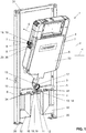
- FIG. 1 to 8 different views of an installation system 1 are shown.
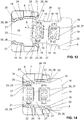
- the Figures 9 to 17 show details of a connecting element 7 according to FIG preferred embodiment of the present invention.
- the connecting element 7 can in the installation system 1 according to the Figures 1 to 8 or can be used in other installation systems.
- the installation system 1 comprises a mounting element 2, a sanitary article 6 and at least one connecting element 7.
- the sanitary article 6 is fastened to the mounting element 2 with the at least one connecting element 7.
- the mounting element 2 can be designed in various ways.
- the mounting element 2 is preferably provided by two profile elements 3, 4 running in the vertical V and at least one profile element 5 running in the horizontal H.
- a further profile element 31 running in the horizontal H is arranged.
- the profile elements 3, 4, 5 and 31 are firmly connected to one another.
- Optional support elements 32 are also arranged here, which connect the profile elements 3, 4 to the profile element 5 running in the horizontal H.
- the support elements 32 provide a corresponding support.
- the profile elements 3, 4 extending in the vertical V preferably comprise a footrest 35 which can be extended telescopically to the profile elements 3, 4.
- the connecting element 7 serves to connect the sanitary article 6 to at least one of the named profile elements 3, 4.
- the connecting element 7 has a connecting part 8 on the sanitary article side and a connecting part 9 on the profile element side.
- the detailed design of the connecting element 7 is based on the Figures 9 to 17 explained in more detail below.
- the bearing structure 11 on the profile element side is arranged on the profile elements 5 running in the horizontal H.
- the at least one connecting element 7 is arranged between the profile elements 3, 4 running in the vertical V and the sanitary article 6.
- two connecting elements 7 are each arranged on the left and right of the sanitary article 6.
- the connecting elements 7 are at the same vertical distance from the bearing structures 10, 11. That is, the connecting elements 7 are at the same height to one another.
- the Figure 8 shows a detailed view of the engagement of the bearing structure 10 on the sanitary article side in the bearing structure 11 on the profile element side the survey arrives.
- the sanitary article-side bearing structure 10 or the elevation 13 is a tab 16 which extends from a flush pipe section 17 to be positioned horizontally, transversely to the said flush pipe section 17.
- the tab 16 extends essentially at right angles from the corresponding flushing pipe section 17.
- the recess 12 is placed in a tab 14 bent out of the profile element 5.
- the tab 16 extends into the recess 12 and is correspondingly pivotable in the recess 12.
- Several recesses 12 can be arranged in the tab 14 so that the sanitary article 6 can be positioned at different positions.
- the sanitary article 6 is pivoted in the direction of its end position towards the mounting element 2.
- the Figures 2 and 5 show the position of the sanitary article 6 in an intermediate position between the starting position and the end position. From this position, the sanitary article is pivoted further, and with the further pivoting the two connecting parts 8, 9 can be brought into contact with one another. The two connecting parts 8, 9 then enter into a firm engagement when the cistern 6 has reached the end position.
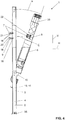
- the connecting part 8 on the sanitary article side can be brought into contact with the connecting part 9 on the profile element side along an insertion movement E.
- the insertion movement E runs essentially on an arc around the pivot axis S.
- the connecting part 8 on the sanitary article side is spaced apart from the connecting part 9 on the profile element side. Only with increasing movement in the direction of the end position is engagement between the two connecting parts 8, 9 created. The engagement thus takes place during the movement of the sanitary article 6 from the starting position into the end position.
- the sanitary article 6 is shown in the starting position.
- the sanitary article 6 is pivoted from this starting position into the end position.
- the pivoting takes place through the pivoting angle ⁇ .
- the pivot angle ⁇ is in the range from 10 ° to 45 °, in particular in the range from 15 ° to 30 °.
- the smaller the pivot angle ⁇ the more compact the installation system 1 is when the sanitary article 6 is in the starting position.
- the pivot axis S is then shown in more detail.
- the pivot axis S here runs parallel to the profile axis P of the profile element 5 and is thus in the horizontal H here.
- the profile axis P is essentially defined as the central axis of the respective profile element, here of the profile element 5.
- the horizontal profile element 5 comprises a plurality of fastening openings 34 on both sides in addition to the bearing structure 11 on the profile element side, which are intended to accommodate threaded rods or other fastening means for fastening further sanitary structures, such as a toilet bowl, to the mounting element 2.
- the connecting element 7 comprises a connecting part 8 on the sanitary article side and a connecting part 9 on the profile element side.
- the two connecting parts 8, 9 can be brought into contact with one another along an insertion movement E and enter into a fixed engagement with one another.
- FIGS 9, 10 and 13th show different perspectives of the connecting element 7, the two connecting parts 8, 9 not yet being in engagement with one another.
- the connecting part 8 is brought into contact with the connecting part 9 along the insertion movement E and then engages firmly.
- this fixed engagement is shown accordingly.
- a corresponding sound-absorbing layer 19 is present.
- the sanitary article 6 is not only in contact with the mounting element 2 via the connecting parts 8, 9, but also via the two bearing structures 10, 11.
- the two bearing structures 10, 11 accordingly also have corresponding contact surfaces 18 via which the Bring bearing structures 10, 11 into contact with one another.
- a corresponding sound-absorbing layer 19 is also arranged between these contact surfaces 18; this sound-absorbing layer 19 is also arranged such that the two bearing structures 10, 11 in engagement with one another are sound-decoupled by the sound-absorbing layer 19.
- the sound-absorbing layer 19 preferably rests on one of two contact surfaces 18 that can be brought into contact with one another, as well as in the Figures 9 to 15 is shown in more detail.
- the sound-absorbing layer 19 is applied to one of the contact surfaces 18 and rests there accordingly.
- the sound-absorbing layer 19 can be glued to the corresponding contact surface with an adhesive.
- the contact surface 18 and the sound-absorbing layer 19 could also be connected to one another in one piece.
- the sound-absorbing layer 19 are accordingly incorporated in one piece on or into the contact surfaces 18.
- the sound-absorbing material is preferably made of an elastic plastic, such as an elastomer or polypropylene or polyethylene.
- the thickness of the sound-absorbing layer 19 is preferably in the range from one millimeter to eight millimeters, in particular from two millimeters to six millimeters.
- the latching connection 20 comprises a latching tab 21, which is arranged on the connecting part 9 on the profile element side, and a latching recess 22, which is arranged on the connecting part 8 on the sanitary article side.
- the latching tab 21 engages in the latching recess 22, the two connecting parts 8, 9 being mechanically firmly latched to one another via the engagement.
- the locked position is in the Figures 10 , 12th and 14th shown. Between the latching tab 21 and the latching recess 22 there is in each case a sound-absorbing layer 19, as was described above. In the case of the latching connection 20, the latching tab 21 or the latching recess 22 provide the corresponding contact surface 18.
- the connecting part 9 on the profile element side has a receiving space 23 and the connecting part 8 on the sanitary article side has an engagement section 27 that can be pushed into the receiving space 23.
- the elements for the latching connection 20 are arranged on the side surfaces 24 of the receiving space 23 and the side surfaces 28 of the engagement section 27.
- the clear width W of the receiving space 23 is seen in the direction of the insertion movement E smaller. That is to say, the latching connections 20, which lie behind the other latching connections 20 in the insertion direction, are arranged closer to one another.
- Each of the locking tabs 20 is articulated to the corresponding connecting part 9 via a spring section 25.
- the latching tab forms a free end 26 of the spring section 25. Due to the arrangement of the spring section 25, the latching tab 21 can correspondingly move back when latched with the latching recess 22 and then spring into the latching recess 22.
- the free end 26 of one locking tab 21 extends in the direction of the insertion movement and the free end 26 of the other locking tab 21 extends counter to the insertion direction E.
- the connecting part 8 on the sanitary article side is connected to the sanitary article 6 via a mechanical connection 29.
- the connecting part 8 on the sanitary article side has corresponding structures for this mechanically fixed connection.
- Latching structures 36 are provided here, which latch onto the sanitary article 6.
- connection part 9 on the profile element side is also connected to the profile element 3, 4, 5 via a mechanically fixed connection 30.
- connection part 9 on the profile element side has corresponding latching structures 37 for this mechanically fixed connection 30.
- a method for assembling the installation system as described above comprises the following steps: In a first step, the sanitary article-side bearing structure 10 and the profile element-side bearing structure 11 are connected to one another.
- the sanitary article 6 is pivoted to the profile elements 3, 4, 5, wherein during the pivoting the sanitary article-side connection part 8 can be brought into contact with the profile-element-side connection part 9 along an insertion movement E, and when the end position is reached, the sanitary article-side connection part 8 with the profile element-side connecting part 9 enters into a firm engagement.
Landscapes
- Engineering & Computer Science (AREA)
- Health & Medical Sciences (AREA)
- Life Sciences & Earth Sciences (AREA)
- Hydrology & Water Resources (AREA)
- Public Health (AREA)
- Water Supply & Treatment (AREA)
- Environmental & Geological Engineering (AREA)
- Sanitary Device For Flush Toilet (AREA)
- Absorbent Articles And Supports Therefor (AREA)
Abstract
Description
- Die vorliegende Erfindung betrifft ein Installationssystem mit einem Sanitärartikel gemäss Anspruch 1.
- Aus dem Stand der Technik sind Unterputz-Installationssysteme für Sanitärelemente bekannt geworden. Beispielsweise vertreibt die Anmelderin unter den Bezeichnungen Geberit GIS und Geberit Duofix entsprechende Installationssysteme. Diese Installationssysteme umfassen jeweils eine Montagestruktur mit vertikalen und horizontalen Profilelementen. Die Profileelemente werden jeweils fest mit einem Gebäude verankert und anschliessend werden die Sanitärartikel, wie Spülkästen, Toilettenschüsseln, Waschtische, Armaturen, Siphons, etc. an der Montagestruktur verbunden.
- Durch den Wasserfluss in den Sanitärartikeln entstehen Geräusche, welche über die Montagestruktur in das Gebäude eingeleitet wird. Die Bewohner empfinden derartige Geräusche als störend.
- Der vorliegenden Erfindung liegt die Aufgabe zugrunde, ein Installationssystem mit einem Sanitärartikel anzugeben, welcher bezüglich Schallgeräusche, die vom Wasserfluss ergehen, geräuschdämmender ausgebildet ist.
- Diese Aufgabe wird mit dem Installationssystem gemäss Anspruch 1 gelöst. Demgemäss umfasst ein Installationssystem ein Montageelement mit mindestens einem Profilelement, einen Sanitärartikel, der am Montageelement zu befestigen ist, und mindestens ein Verbindungselement zur Verbindung des Sanitärartikels mit dem mindestens einen Profilelement, wobei das Verbindungselement ein sanitärartikelseitiges Verbindungsteil und ein profilelementseitiges Verbindungsteil aufweist. Das sanitärartikelseitige Verbindungsteil ist mit dem profilelementseitigen Verbindungsteil entlang einer Einschubbewegung in Kontakt bringbar und geht einen festen Eingriff ein. Die beiden Verbindungsteile kommen über an den Verbindungsteilen liegende Kontaktflächen miteinander in Kontakt. Weiterhin ist ein schalldämmendes Material vorhanden, welches derart angeordnet ist, dass die beiden Verbindungsteile zueinander schallentkoppelt sind, wenn diese sich im festen Eingriff miteinander befinden.
- Durch die Anordnung des schalldämmenden Materials ergeht der Vorteil, dass die Schallbrücke zwischen dem Sanitärartikel und dem Montageelement im Bereich der Verbindungselemente unterbrochen werden kann. Hierdurch kann eine Weiterleitung von Schall, der vom Wasserfluss im Sanitärartikel oder durch Öffnen bzw. Verschliessen von Ventilen, entsteht, vom Sanitärartikel zum Montageelement mindestens teilweise oder gar ganz vermieden werden. Falls der Sanitärartikel ein Spülkasten ist, tritt ein entsprechender Wasserfluss durch die Befüllung des Spülkastens und die Entleerung bei einer Spülung auf.
- In einer ersten Ausführungsform des schalldämmenden Materials weist das schalldämmende Material die Gestalt einer schalldämmenden Schicht auf. Zwischen den Kontaktflächen ist eine schalldämmende Schicht derart angeordnet, dass die beiden Verbindungsteile im festen Eingriff zueinander durch die schalldämmende Schicht voneinander schallentkoppelt sind.
- Vorzugsweise ist zwischen sämtlichen Kontaktflächen zwischen den beiden Verbindungsteilen eine entsprechende schalldämmende Schicht vorhanden.
- Vorzugsweise liegt die schalldämmende Schicht auf einer von zwei gegenüberliegenden Kontaktflächen auf. Die schalldämmende Schicht kann beispielsweise auf der jeweiligen Kontaktfläche aufgeklebt werden.
- Alternativ kann die schalldämmende Schicht auf oder in eine von zwei gegenüberliegenden Kontaktflächen einstückig eingearbeitet sein. Beispielsweise kann die schalldämmende Schicht bei der Herstellung der Verbindungsteile im Rahmen eines Mehrkomponenten-Spritzgiessverfahrens aufgebracht werden.
- Vorzugsweise sind eine erste Kontaktfläche und eine zweite Kontaktfläche einander zugewandt und eine dritte Kontaktfläche ist im Wesentlichen rechtwinklig zu der ersten und der zweiten Kontaktfläche orientiert. Hierdurch ergeht der Vorteil, dass die Schallübertragung in zwei unterschiedliche Richtungen unterbrochen wird.
- Vorzugsweise wird die schalldämmende Schicht aus einem elastischen Kunststoff, wie ein Elastomer oder Polypropylen oder Polyethylen bereitgestellt. Weiter weist die schalldämmende Schicht eine Dicke im Bereich von 1 Millimeter bis 8 Millimeter, insbesondere von 2 Millimeter bis 6 Millimeter auf. Die Schicht kann aber auch dicker als 8 Millimeter sein.
- In einer zweiten Ausführungsform ist eines oder sind beide Verbindungsteile vollständig oder mehrheitlich aus einem schalldämmenden Material. Vorzugsweise ist das schalldämmende Material ein elastischer Kunststoff, wie ein Elastomer oder Polypropylen oder Polyethylen. Bei dieser Ausführungsform wird der Kunststoff bei der Herstellung vorzugsweise expandiert, was dann zu einem entsprechenden Formteil führt. Besonders bevorzugt können Befestigungselemente, wie Schrauben, Gewindeteile oder ähnliches während der Herstellung eingelegt werden, wobei diese Befestigungselemente entsprechend fest mit dem Kunststoff verbunden werden.
- Vorzugsweise steht das sanitärartikelseitige Verbindungsteil gemäss beiden Ausführungsformen mit dem profilelementseitigen Verbindungsteil über mindestens eine Rastverbindung im Eingriff. Bei der ersten Ausführungsform weist die Rastverbindung die besagte Kontaktfläche mit der besagten schalldämmende Schicht auf. Die schalldämmende Schicht ist demnach im Bereich der Rastverbindung angeordnet. Die Elemente der Rastverbindung weisen die besagte Kontaktfläche auf.
- Vorzugsweise weist die Rastverbindung bei beiden Ausführungsformen eine Rastlasche an einem der Verbindungsteile und eine Rastausnehmung am anderen der Verbindungsteile auf, wobei die Rastlasche in die Rastausnehmung eingreift und wobei über das Eingreifen die beiden Verbindungsteile miteinander mechanisch fest verrastet sind. Die Kontaktfläche wird durch die Rastlasche und die Rastausnehmung bereitgestellt.
- Vorzugsweise sind mindestens zwei Rastverbindungen angeordnet, wobei die Rastverbindungen bezüglich der Richtung der Einschubbewegung gegenüber einander angeordnet sind und ein Paar von Rastverbindungen bilden.
- Besonders bevorzugt sind zwei Paare von Rastverbindungen in Richtung der Einschubbewegung beabstandet zueinander vorhanden.
- Vorzugsweise weist eines der Verbindungsteile einen Aufnahmeraum auf und das andere der Verbindungsteile weist einen in den Aufnahmeraum einschiebbaren Eingriffsabschnitt auf. Der Eingriffsabschnitt ist in den Aufnahmeraum einschiebbar. Die Elemente für die Rastverbindung, insbesondere die Rastlasche und die Rastausnehmung, sind an Seitenflächen des Aufnahmeraums und an Seitenflächen des Eingriffsabschnitts angeordnet.
- Bei der Anordnung mit den zwei Paaren von Rastverbindungen sind pro Seitenfläche jeweils zwei Rastlaschen bzw. zwei Rastausnehmungen vorhanden.
- Vorzugsweise wird die lichte Weite des Aufnahmeraums in Richtung der Einschubbewegung gesehen kleiner wird.
- Vorzugsweise ist jede der Rastlaschen über einen Federabschnitt am Verbindungsteil angelenkt und bildet ein freies Ende des Federabschnitts. Das freie Ende kann in Richtung der Einschubbewegung und/oder entgegen der Einschubrichtung orientiert sein. Sofern zwei Rastlaschen vorhanden sind, ist es denkbar, dass das freie Ende der einen Rastlasche in Richtung der Einschubbewegung und das freie Ende der anderen Rastlasche entgegen der Einschubrichtung orientiert ist.
- Die Rastlasche kann als freischwingender Arm ausgebildet sein. Alternativerweise kann die Rastlasche auch als festgelegter Arm ausgebildet sein.
- Vorzugsweise ist das sanitärartikelseitige Verbindungsteil mit dem Sanitärartikel über eine mechanisch feste Verbindung verbunden, wobei die mechanisch feste Verbindung vorzugsweise eine Rastverbindung ist. Alternativerweise ist das sanitärartikelseitige Verbindungsteil einstückig am Sanitärartikel angeformt.
- Vorzugsweise ist das profilelementseitige Verbindungsteil mit dem Profilelement über eine mechanisch feste Verbindung verbunden, wobei die mechanisch feste Verbindung vorzugsweise eine Rastverbindung oder eine Schraubverbindung ist. Alternativerweise ist das profilelementseitige Verbindungsteil einstückig am Profilelement angeformt. Gemäss einer Weiterbildung weist der Sanitärartikel weiter eine sanitärartikelseitige Lagerstruktur und eines der genannten Profilelemente weist eine profilelementseitige Lagerstruktur auf. In dieser Weiterbildung ist das Montageelement mit mindestens zwei in der Vertikalen verlaufenden Profilelementen und mit mindestens einem in der Horizontalen verlaufenden Profilelement ausgebildet. Die Lagerstrukturen sind bei der Montage des Sanitärartikels miteinander in Eingriff bringbar, wobei der Eingriff derart ist, dass der Sanitärartikel von einer Ausgangsposition in eine Endposition um eine Schwenkachse verschwenkbar ist. Bei der Verschwenkung ist das sanitärartikelseitige Verbindungsteil mit dem profilelementseitiges Verbindungsteil entlang einer Einschubbewegung in Kontakt bringbar und bei Erreichen der Endposition geht das sanitärartikelseitige Verbindungsteil mit dem profilelementseitiges Verbindungsteil einen festen Eingriff ein.
- Durch die Verschwenkung des Sanitärartikels ergeht der Vorteil, dass eine einfache und intuitive Art der Montage bereitgestellt wird. Insbesondere kann der Sanitärartikel aufgrund dessen Abstützung über die Lagerstrukturen von einer Person sehr einfach alleine, das heisst ohne Zuhilfenahme einer weiteren Person, montiert werden. Weiter entfällt ein mühsames Festhalten des Sanitärartikels und ein gleichzeitiges Manipulieren von Befestigungselementen, weil der Sanitärartikel über die Lagerstruktur gestützt und bewegbar ist.
- Ein weiterer Vorteil ist, dass bei engen Platzverhältnissen der Sanitärartikel von oben oder von der Seite über die Lagerstrukturen in Kontakt mit dem Montageelement gebracht werden kann und dann entsprechend verschwenkt wird. Eine Montage von der Frontseite, die üblicherweise viel Platz benötigt, weil nebst dem Sanitärartikel auch noch der Installateur sich vor dem Montageelement positionieren muss, wird einfacher. Dadurch, dass die Montage aufgrund der Verschwenkung von oben her oder von der Seite her erfolgen kann, wird das Platzproblem entschärft.
- Die genannten Vorteile werden nicht nur bei der Montage, sondern auch bei der Demontage des Spülkastens erzielt.
- Vorzugsweise kommen die beiden Lagerstrukturen über an den Lagerstrukturen liegende Kontaktflächen miteinander in Kontakt. Ebenfalls ist vorteilhafterweise im Bereich der Lagerstrukturen ein oben genanntes schalldämmendes Material vorhanden. Das schalldämmende Material kann eine zwischen den Kontaktflächen angeordnete schalldämmende Schicht sein. Die Schicht ist derart angeordnet, dass die beiden Lagerstrukturen im festen Eingriff zueinander durch die schalldämmende Schicht schallentkoppelt sind. Auch kann eine oder beide der Lagerstrukturen aus dem schalldämmenden Material ausgebildet sein. Hierdurch kann die Schallübertragung im Bereich der Lagerstelle ebenfalls vermieden werden.
- Die Schwenkachse verläuft vorzugsweise parallel und beabstandet zur Profilachse des Profilelements, an dem die profilelementseitige Lagerstruktur angeordnet ist. Je nach Ausbildung der Lagerstrukturen kann sich die Schwenkachse bei der Verschwenkung auch parallel zur Profilachse verschieben. Es handelt sich demnach nicht zwangsläufig um eine immer gleich liegende Schwenkachse. Die Lagerstrukturen können aber auch derart ausgebildet sein, dass die Schwenkachse über die gesamte Schwenkbewegung an der gleichen Position liegt.
- Die Einschubbewegung ist aufgrund der Verschwenkbewegung des Sanitärartikels eine im Wesentlichen bogenartige Bewegung. Das Zentrum des Bogens bildet die Schwenkachse.
- Bevorzugt ist, dass in der Ausgangslage das sanitärartikelseitige Verbindungsteil beabstandet zum profilelementseitigen Verbindungsteil und dass erst mit zunehmender Bewegung in Richtung der Endposition ein Eingriff zwischen den beiden Verbindungsteilen geschaffen wird.
- Hierdurch ergeht der Vorteil, dass das Verbinden des Sanitärartikels mit dem Montageelement über die beiden Lagerstrukturen unabhängig vom Verbindungselement erfolgen kann, was die Montage einfacher gestaltet.
- In einer Ausführungsform ist die profilelementseitige Lagerstruktur an dem in der Horizontalen verlaufenden Profilelement angeordnet und mindestens ein Verbindungselement ist zwischen den in der Vertikalen verlaufenden Profilelementen und dem Sanitärartikel angeordnet.
- In einer anderen Ausführungsform ist die profilelementseitige Lagerstruktur an dem in der Vertikalen verlaufenden Profilelement angeordnet und mindestens ein Verbindungselement ist zwischen dem in der Horizontalen verlaufenden Profilelement und dem Sanitärartikel angeordnet.
- Vorzugsweise ist beidseitig zum Sanitärartikel jeweils ein Verbindungselement angeordnet, wobei die Verbindungselemente jeweils in einem gleichen Abstand zur sanitärartikelseitigen Lagerstruktur bzw. zur profilelementseitigen Lagerstruktur liegen.
- Durch diese Anordnung ist der Sanitärartikel an drei Punkten, nämlich an zwei Verbindungselementen und an der Lagerstruktur am Montageelement gelagert. Die Anordnung der beiden Verbindungselemente mit dem besagten Abstand zu den Lagerstrukturen hat zudem den Vorteil, dass eine symmetrische Kraftverteilung bei der Herstellung der Verbindung der Verbindungsteile miteinander erreicht werden kann.
- Vorzugsweise ist eine der beiden Lagerstrukturen als Ausnehmung ausgebildet und die andere der beiden Lagerstrukturen ist als Erhebung ausgebildet, wobei die Erhebung schwenkbar in die Ausnehmung eingreift.
- Vorzugsweise ist die profilelementseitige Lagerstruktur als Ausnehmung und die sanitärartikelseitige Lagerstruktur als Erhebung ausgebildet. Eine umgekehrte Anordnung wäre auch denkbar.
- Besonders bevorzugt ist die Ausnehmung in einer aus dem Profilelement herausgebogenen Lasche angeordnet. Bevorzugt können mehrere Ausnehmungen angeordnet sein. Es ist aber auch denkbar, dass nur eine Ausnehmung vorhanden ist.
- Vorzugsweise wird der Sanitärartikel von der Ausgangsposition in die Endposition um einen Schwenkwinkel im Bereich von 10° bis 45°, insbesondere im Bereich von 15° bis 30°, verschwenkt. Gerade beim Einsatz von Werkzeugen, wie Bohrmaschinen, vor der Lagerstruktur sind diese Winkel vorteilhaft.
- Vorzugsweise ist zwischen der sanitärartikelseitigen Lagerstruktur und der profilelementseitigen Lagerstruktur Spiel in eine Richtung quer zur Schwenkachse bzw. zur Profilachse vorhanden, wobei das Spiel vorzugsweise derart bemessen ist, dass Toleranzen zwischen den Lagerstrukturen und dem mindestens einen Verbindungselement ausgleichbar sind.
- Vorzugsweise ist der Sanitärartikel ein Spülkasten mit einem Spülrohr. Andere Sanitärartikel, wie Siphonelemente, Abflusselemente oder Einbaublöcke für Auslaufarmaturen sind aber auch denkbar.
- Im Fall des Spülkastens liegen die sanitärartikelseitige Lagerstruktur am Spülkasten oder am Spülrohr an und erstrecken sich vom Spülkasten oder vom Spülrohr weg.
- Vorzugsweise ist die sanitärartikelseitige Lagerstruktur eine Lasche, welche sich von einem in der Horizontalen zu positionierenden Spülrohrabschnitt quer zum besagten Spülrohrabschnitt weg erstreckt.
- Vorzugsweise ist die Lasche am Spülrohr angeformt und ist somit einteilig mit dem Spülrohr in Verbindung. Alternativerweise kann die Lasche eine kreisrunde Aufnahme aufweisen. Über diese Aufnahme kann die Lasche dann am Spülrohr gelagert werden.
- Vorzugsweise sind die Profilelemente aus Metall, wobei das horizontale Profilelement über eine mechanisch feste Verbindung mit den vertikalen Profilelementen verbunden ist. Die mechanisch feste Verbindung eine Schraubverbindung oder eine Schweissverbindung. In anderen Varianten ist es aber auch denkbar, dass die Profilelemente aus Holz sind. Weiter weist mindestens das in der Horizontalen verlaufende Profilelement Befestigungsstellen auf, über welche weitere Sanitärartikel zum Montageelement befestigt werden können. Die Profilelemente können weiter über Stützelemente zueinander abgestützt sein. Die in der Vertikalen verlaufenden Profileelement umfassen bevorzugt jeweils eine teleskopisch ausziehbare Fussstütze. Zudem können die Profilelemente und/oder die Fussstütze mit Befestigungsöffnungen versehen sein, so dass das Montageelement über Schrauben oder dergleichen mit einem Gebäude verbunden werden kann.
- Ein Verfahren zur Montage eines Installationssystems nach obiger Beschreibung ist dadurch charakterisiert,
dass in einem ersten Schritt die sanitärartikelseitige Lagerstruktur und die profilelementseitige Lagerstruktur miteinander verbunden werden,
dass in einem nachfolgenden zweiten Schritt der Sanitärartikel zu den Profilelementen verschwenkt wird und
dass bei der Verschwenkung das sanitärartikelseitige Verbindungsteil mit dem profilelementseitiges Verbindungsteil entlang einer Einschubbewegung in Kontakt bringbar ist und bei Erreichen der Endposition das sanitärartikelseitige Verbindungsteil mit dem profilelementseitiges Verbindungsteil einen festen Eingriff eingeht. - Weitere Ausführungsformen sind in den abhängigen Ansprüchen angegeben.
- Bevorzugte Ausführungsformen der Erfindung werden im Folgenden anhand der Zeichnungen beschrieben, die lediglich zur Erläuterung dienen und nicht einschränkend auszulegen sind. In den Zeichnungen zeigen:
- Fig. 1
- eine perspektivische Ansicht eines Installationssystems gemäss einer Ausführungsform der vorliegenden Erfindung, wobei sich ein Sanitärartikel in der Ausgangsposition befindet;
- Fig. 2
- eine perspektivische Ansicht des Installationssystems gemäss der
Figur 1 , wobei sich der Sanitärartikel zwischen der Ausgangsposition und der Endposition befindet; - Fig. 3
- eine perspektivische Ansicht des Installationssystems gemäss der
Figur 1 , wobei sich der Sanitärartikel in der Endposition befindet; - Fig. 4
- eine Seitenansicht eines Installationssystems gemäss
Figur 1 ; - Fig. 5
- eine Seitenansicht eines Installationssystems gemäss
Figur 2 ; - Fig. 6
- eine Seitenansicht eines Installationssystems gemäss
Figur 3 ; - Fig. 7
- eine teilweise geschnittene Ansicht des Installationssystems gemäss den vorhergehenden Figuren;
- Fig. 8
- eine Detailansicht des Installationssystems gemäss den vorhergehenden Figuren;
- Fig. 9
- eine Detailansicht eines Verbindungselements des Installationssystems gemäss den vorhergehenden Figuren vor der Verbindung;
- Fig. 10
- die Detailansicht gemäss der
Figur 9 im verbundenen Zustand; - Fig. 11
- eine weitere Detailansicht eines Verbindungselements des Installationssystems gemäss den vorhergehenden Figuren vor der Verbindung;
- Fig. 12
- die Detailansicht gemäss der
Figur 11 im verbundenen Zustand; - Fig. 13
- eine weitere Detailansicht eines Verbindungselements des Installationssystems gemäss den vorhergehenden Figuren vor der Verbindung;
- Fig. 14
- die Detailansicht gemäss der
Figur 13 im verbundenen Zustand; und - Fig. 15
- eine Detailansicht des Verbindungselements nach den
Figuren 9 bis 14 . - In den
Figuren 1 bis 8 werden verschiedene Ansichten eines Installationssystems 1 gezeigt. DieFiguren 9 bis 17 zeigen Details eines Verbindungselementes 7 gemäss einer bevorzugten Ausführungsform der vorliegenden Erfindung. Das Verbindungselement 7 kann im Installationssystem 1 gemäss denFiguren 1 bis 8 oder in anderen Installationssystemen eingesetzt werden kann. - Das Installationssystem 1 umfasst ein Montageelement 2, einen Sanitärartikel 6 und mindestens ein Verbindungselement 7. Der Sanitärartikel 6 wird mit dem mindestens einen Verbindungselement 7 zum Montageelement 2 befestigt.
- Das Montageelement 2 kann verschiedenartig ausgebildet sein. Vorzugsweise wird das Montageelement 2 durch zwei in der Vertikalen V verlaufende Profilelemente 3, 4 und mindestens einem in der Horizontalen H verlaufenden Profilelement 5 bereitgestellt. In der gezeigten Ausführungsform ist noch ein weiteres in der Horizontalen H verlaufendes Profilelement 31 angeordnet. Die Profilelement 3, 4, 5 und 31 sind fest miteinander verbunden. Weiter sind hier optionale Stützenelemente 32 angeordnet, welche die Profilelemente 3, 4 mit dem in der Horizontalen H verlaufenden Profilelement 5 verbinden. Die Stützenelemente 32 sorgen für eine entsprechende Abstützung. Vorzugsweise umfassen die in der Vertikalen V verlaufenden Profilelemente 3, 4 eine teleskopisch zu den Profilelemente 3, 4 ausfahrbare Fussstütze 35 auf.
- Der Sanitärartikel 6 ist in der gezeigten Ausführungsform ein Spülkasten. Der Spülkasten umfasst einen Kastenkörper 33, von welchem sich unterseitig ein Spülrohr 15 wegerstreckt. Der Kastenkörper 33 dient der Aufnahme von Spülwasser, welches dann über das Spülrohr 15 zu einer Toilette abgegeben werden kann. Der Sanitärartikel 6 kann aber auch ein anderes Sanitärelement sein.
- Das Verbindungselement 7 dient der Verbindung des Sanitärartikels 6 mit mindestens einem der genannten Profilelemente 3, 4. Das Verbindungselement 7 weist ein sanitärartikelseitiges Verbindungsteil 8 und ein profilelementseitiges Verbindungsteil 9 auf. Die detaillierte Ausbildung der Verbindungselementes 7 wird anhand der
Figuren 9 bis 17 weiter unten genauer erläutert. - Weiter umfasst der Sanitärartikel 6 eine sanitärartikelseitige Lagerstruktur 10 und eines der genannten Profilelemente, hier das in der Horizontalen H verlaufende Profilelement 5, umfasst eine profilelementseitige Lagerstruktur 11. Bei der Montage des Sanitärartikels 6 zum Montageelement 2 sind die Lagerstrukturen 10, 11 miteinander in Eingriff bringbar. Der Eingriff ist dabei derart, dass der Sanitärartikel 6 von einer Ausgangsposition in eine Endposition um eine Schwenkachse S verschwenkbar ist. Die Lagerstrukturen 10, 11 sind dabei derart ausgebildet, dass der Sanitärartikel 6 kontrolliert verschwenkt werden kann.
- In der gezeigten Ausführungsform gemäss den
Figuren 1 bis 8 ist die profilelementseitige Lagerstruktur 11 an den in der Horizontalen H verlaufenden Profilelementen 5 angeordnet. Das mindestens eine Verbindungselement 7 ist zwischen den in der Vertikalen V verlaufenden Profilelementen 3, 4 und dem Sanitärartikel 6 angeordnet. In der gezeigten Ausführungsform sind zwei Verbindungselemente 7 jeweils links und rechts zum Sanitärartikel 6 angeordnet. Die Verbindungselemente 7 liegen dabei im gleichen vertikalen Abstand zu den Lagerstrukturen 10, 11. Das heisst, die Verbindungselemente 7 liegen auf gleicher Höhe zueinander. - In den
Figuren 1 ,4 und7 sowie 8 wird der Sanitärartikel 6 in seiner Ausgangslage gezeigt. In der Ausgangslage sind die beiden Lagerstrukturen 10, 11 miteinander im Eingriff und der Sanitärartikel 6 kann entsprechend verschwenkt werden. - Die
Figur 8 zeigt eine Detailansicht des Eingriffs der sanitärartikelseitigen Lagerstruktur 10 in die profilelementseitige Lagerstruktur 11. Eine der Lagerstrukturen, hier die sanitärartikelseitige Lagerstruktur 10, ist als Erhebung 13 ausgebildet und die andere der Lagerstrukturen, hier die profilelementseitige Lagerstruktur 11, ist als Ausnehmung 12 ausgebildet, in welche die Erhebung einragt. In der gezeigten Ausführungsform ist die sanitärartikelseitige Lagerstruktur 10 bzw. die Erhebung 13 eine Lasche 16, welche sich von einem in der Horizontalen zu positionierenden Spülrohrabschnitt 17 quer zum besagten Spülrohrabschnitt 17 wegerstreckt. Die Lasche 16 erstreckt sich dabei im Wesentlichen rechtwinklig vom entsprechenden Spülrohrabschnitt 17 ab. Die Ausnehmung 12 ist in der gezeigten Ausführungsform in einer aus dem Profilelement 5 herausgebogenen Lasche 14 platziert. Die Lasche 16 erstreckt sich in die Ausnehmung 12 hinein und ist in der Ausnehmung 12 entsprechend verschwenkbar. Es können mehrere Ausnehmungen 12 in der Lasche 14 angeordnet sein, so dass der Sanitärartikel 6 an unterschiedlichen Positionen positioniert werden kann. - De Lagerstrukturen 10, 11 sind in der gezeigten Ausführungsform derart ausgebildet, dass der Sanitärartikel 6 mit seiner in den Figuren gezeigten winkligen Ausrichtung von oben her in Richtung der profilelementseitigen Lagerstruktur 11 in Eingriff gebracht werden kann. Diese Bewegung wird in der
Figur 4 durch den Pfeil B dargestellt. Der Sanitärartikel 6 kann also von oben her mit einer winkligen Ausrichtung zur Vertikalen entlang der Bewegung B mit seiner Lagerstruktur 10 in die profilelementseitige Lagerstruktur 11 eingesetzt werden. - Ausgehend von der Ausgangslage, wie in den
Figuren 1 ,4 ,7 und8 gezeigt, wird der Sanitärartikel 6 in Richtung seiner Endlage zum Montageelement 2 hin verschwenkt. - Die
Figuren 2 und5 zeigen die Position des Sanitärartikels 6 in einer Zwischenposition zwischen der Ausgangsposition und der Endposition. Aus dieser Position wird der Sanitärartikel weiter verschwenkt und bei der weiteren Verschwenkung sind die beiden Verbindungsteile 8, 9 miteinander in Kontakt bringbar. Die beiden Verbindungsteile 8, 9 gehen dann einen festen Eingriff ein, wenn der Spülkasten 6 die Endposition erreicht hat. - In der
Figur 5 wird gezeigt, dass das sanitärartikelseitige Verbindungsteil 8 mit dem profilelementseitigen Verbindungsteil 9 entlang einer Einschubbewegung E in Kontakt bringbar ist. Die Einschubbewegung E verläuft im Wesentlichen auf einem Kreisbogen um die Schwenkachse S. Von denFiguren 4 ,5 und6 wird ersichtlich, dass in der Ausgangslage das sanitärartikelseitige Verbindungsteil 8 beabstandet zum profilelementseitigen Verbindungsteil 9 liegt. Erst mit zunehmender Bewegung in Richtung der Endposition wird ein Eingriff zwischen den beiden Verbindungsteilen 8, 9 geschaffen. Der Eingriff erfolgt also während der Bewegung des Sanitärartikels 6 von der Ausgangsposition in die Endposition. - In der
Figur 4 wird der Sanitärartikel 6 in der Ausgangsposition gezeigt. Von dieser Ausgangsposition wird der Sanitärartikel 6 in die Endposition verschwenkt. Die Verschwenkung erfolgt dabei um den Schwenkwinkel α. Der Schwenkwinkel α liegt im Bereich von 10° bis 45°, insbesondere im Bereich von 15° bis 30°. Je kleiner der Verschwenkwinkel α, desto kompakter ist das Installationssystem 1, wenn sich der Sanitärartikel 6 in der Ausgangsposition befindet. In derFigur 8 wird sodann die Schwenkachse S genauer gezeigt. Die Schwenkachse S verläuft hier parallel zur Profilachse P des Profilelements 5 und liegt hier somit in der Horizontalen H. Die Profilachse P definiert sich im Wesentlichen als Mittelachse des jeweiligen Profilelementes, hier vom Profilelement 5. - Weiter ist zwischen der sanitärartikelseitigen Lagerstruktur 10 und der profilelementseitigen Lagerstruktur 11 Spiel in einer Richtung quer zur Schwenkachse S bzw. zur Profilachse P vorhanden. Dieses Spiel ist dabei so bemessen, dass Toleranzen zwischen den Lagerstrukturen 10, 11 und dem mindestens einem Verbindungselement 7 ausgleichbar sind. Dies insbesondere für den Fall, dass die Verbindungselemente 7 ungenau montiert werden.
- Weiter umfasst das horizontale Profilelement 5 in der gezeigten Ausführungsform beidseitig neben der profilelementseitigen Lagerstruktur 11 eine Vielzahl von Befestigungsöffnungen 34, welche der Aufnahme von Gewindestangen oder anderen Befestigungsmitteln für die Befestigung von weiterer Sanitärstrukturen, wie beispielsweise eine Toilettenschüssel an das Montageelement 2 vorgesehen sind.
- Anhand der
Figuren 9 bis 17 wird nun eine bevorzugte Ausführungsform des Verbindungselementes 7 gezeigt. Das Verbindungselement 7 umfasst, wie oben erwähnt, ein sanitärartikelseitiges Verbindungsteil 8 und ein profilelementseitiges Verbindungsteil 9. Die beiden Verbindungsteile 8, 9 sind entlang einer Einschubbewegung E miteinander in Kontakt bringbar und gehen miteinander einen festen Eingriff ein. - Die
Figuren 9, 10 und13 zeigen verschiedene Perspektiven des Verbindungselementes 7, wobei die beiden Verbindungsteile 8, 9 noch nicht im Eingriff miteinander stehen. Das Verbindungsteil 8 wird entlang der Einschubbewegung E mit dem Verbindungsteil 9 in Kontakt gebracht und geht dann einen festen Eingriff ein. In denFiguren 10 ,12 und14 wird dieser feste Eingriff entsprechend dargestellt. - Die beiden Verbindungsteile 8, 9 kommen über Kontaktflächen 18, die an den Verbindungsteilen 8, 9 vorhanden sind, miteinander in Kontakt. Weiterhin ist ein schalldämmendes Material vorhanden, welches derart angeordnet ist, dass die beiden Verbindungsteile 8, 9 zueinander schallentkoppelt sind, wenn diese im festen Eingriff zueinander sind. In der gezeigten Ausführungsform ist zwischen den Kontaktflächen 18 ist eine schalldämmende Schicht 19 angeordnet. Die schalldämmende Schicht 19 ist dabei derart angeordnet, dass wenn sich die beiden Verbindungsteile 8, 9 im festen Eingriff zueinander befinden, durch die schalldämmende Schicht 19 schallentkoppelt sind. Die schalldämmende Schicht 19 ist dabei derart ausgebildet, dass allfälliger Schall, der vom Sanitärartikel 6 herrührt, nicht vom sanitärartikelseitigen Verbindungsteil 8 auf das profilelementseitige Verbindungsteil 9 übergeht. Die schalldämmende Schicht 19 wirkt einer möglichen Schallbrücke entsprechend entgegen. In einer anderen Ausführungsform ist eines oder beide der Verbindungsteile 8, 9 mehrheitlich oder ganz aus dem schalldämmenden Material.
- Vorzugsweise ist zwischen sämtlichen Kontaktflächen zwischen den beiden Verbindungsteilen 8, 9 eine entsprechende schalldämmende Schicht 19 vorhanden.
- In der gezeigten Ausführungsform steht der Sanitärartikel 6 nicht nur über die Verbindungsteile 8, 9 mit dem Montageelement 2 in Kontakt, sondern auch über die beiden Lagerstrukturen 10, 11. Auch die beiden Lagerstrukturen 10, 11 weisen demnach entsprechende Kontaktflächen 18 auf, über welche die Lagerstrukturen 10, 11 miteinander in Kontakt bringen. Auch zwischen diesen Kontaktflächen 18 ist eine entsprechende schalldämmende Schicht 19 angeordnet, diese schalldämmende Schicht 19 ist ebenfalls derart angeordnet, dass die beiden Lagerstrukturen 10, 11 im Eingriff zueinander durch die schalldämmende Schicht 19 schallentkoppelt sind.
- Vorzugsweise liegt die schalldämmende Schicht 19 auf einer von zwei miteinander in Kontakt bringbare Kontaktflächen 18 auf, sowie dies in den
Figuren 9 bis 15 genauer dargestellt ist. Die schalldämmende Schicht 19 wird dabei auf eine der Kontaktflächen 18 aufgebracht und liegt dort entsprechend auf. Beispielsweise kann die schalldämmende Schicht 19 auf die entsprechende Kontaktfläche mit einem Kleber aufgeklebt werden. Alternativerweise könnte die Kontaktfläche 18 und die schalldämmende Schicht 19 auch einstückig miteinander verbunden sein. Beispielsweise wäre es denkbar, dass die schalldämmende Schicht 19 auf oder in die Kontaktflächen 18 entsprechend einstückig eingearbeitet sind. - Die schalldämmende Material ist vorzugsweise aus einem elastischen Kunststoff, wie aus einem Elastomer oder Polypropylen oder Polyethylen bereitgestellt. Die Dicke der schalldämmenden Schicht 19 liegt vorzugsweise im Beriech von einem Millimeter bis acht Millimeter, insbesondere von zwei Millimeter bis sechs Millimeter.
- In der gezeigten Ausführungsform steht das sanitärartikelseitige Verbindungsteil 8 mit dem profilelementseitigen Verbindungsteil 9 über mindestens eine Rastverbindung 20 im Eingriff. In der gezeigten Ausführungsform sind insgesamt vier Rastverbindungen 20 vorgesehen. Jeweils zwei Rastverbindungen 20 liegen bezüglich der Richtung der Einschubbewegung E gegenüber einander und bilden ein Paar von Rastverbindungen 20. In der gezeigten Ausführungsform sind zwei Paare von Rastverbindungen 20 in Richtung der Einschubbewegung E beabstandet zueinander angeordnet.
- Die Rastverbindung 20 umfasst in der gezeigten Ausführungsform eine Rastlasche 21, die am profilelementseitigen Verbindungsteil 9 angeordnet ist und eine Rastausnehmung 22, die am sanitärartikelseitigen Verbindungsteil 8 angeordnet ist. In der Eingriffslage greift die Rastlasche 21 in die Rastausnehmung 22 ein, wobei über das Eingreifen die beiden Verbindungsteile 8, 9 miteinander mechanisch fest verrastet sind. Die verrastete Position wird in den
Figuren 10 ,12 und14 gezeigt. Zwischen der Rastlasche 21 und der Rastausnehmung 22 liegt dabei jeweils eine schalldämmende Schicht 19, sowie dies oben beschrieben wurde. Im Falle der Rastverbindung 20 stellen dabei die Rastlasche 21 bzw. die Rastausnehmung 22 die entsprechende Kontaktfläche 18 bereit. - In der gezeigten Ausführungsform weist das profilelementseitige Verbindungsteil 9 einen Aufnahmeraum 23 auf und das sanitärartikelseitige Verbindungsteil 8 weist einen in den Aufnahmeraum 23 einschiebbaren Eingriffsabschnitt 27 auf. Die Elemente für die Rastverbindung 20 sind dabei an den Seitenflächen 24 des Aufnahmeraumes 23 und den Seitenflächen 28 des Eingriffsabschnittes 27 angeordnet. Die lichte Weite W des Aufnahmeraumes 23 wird in Richtung der Einschubbewegung E gesehen kleiner. Das heisst, die Rastverbindungen 20, welche in Einschubrichtung hinter den anderen Rastverbindungen 20 liegen, sind näher zueinander angeordnet.
- Jede der Rastlaschen 20 ist über einen Federabschnitt 25 am entsprechenden Verbindungsteil 9 angelenkt. Die Rastlasche bildet dabei ein freies Ende 26 des Federabschnittes 25. Durch die Anordnung des Federabschnittes 25 kann die Rastlasche 21 bei Verrastung mit der Rastausnehmung 22 entsprechend zurück weichen und dann in die Rastausnehmung 22 einfedern. In der gezeigten Ausführungsform erstreckt sich das freie Ende 26 der einen Rastlasche 21 in Richtung der Einschubbewegung und das freie Ende 26 der anderen Rastlasche 21 erstreckt sich entgegen der Einschubrichtung E.
- Weiter ist das sanitärartikelseitige Verbindungsteil 8 mit dem Sanitärartikel 6 über eine mechanische Verbindung 29 verbunden. In der gezeigten Ausführungsform weist das sanitärartikelseitige Verbindungsteil 8 entsprechende Strukturen für diese mechanisch feste Verbindung auf. Hier sind Raststrukturen 36 vorhanden, welche am Sanitärartikel 6 einrasten.
- Weiter ist das profilelementseitige Verbindungsteil 9 mit dem Profilelement 3, 4, 5 ebenfalls über eine mechanisch feste Verbindung 30 verbunden. In der
Figur 15 kann gut erkannt werden, dass das profilelementseitige Verbindungsteil 9 entsprechende Raststrukturen 37 für diese mechanisch feste Verbindung 30 aufweist. - Ein Verfahren zur Montage des Installationssystems nach obiger Beschreibung umfasst folgende Schritte:
In einem ersten Schritt werden die sanitärartikelseitige Lagerstruktur 10 und die profilelementseitige Lagerstruktur 11 miteinander verbunden. - In einem nachfolgenden zweiten Schritt wird der Sanitärartikel 6 zu den Profilelementen 3, 4, 5 verschwenkt wird, wobei bei der Verschwenkung das sanitärartikelseitige Verbindungsteil 8 mit dem profilelementseitiges Verbindungsteil 9 entlang einer Einschubbewegung E in Kontakt bringbar ist und bei Erreichen der Endposition das sanitärartikelseitige Verbindungsteil 8 mit dem profilelementseitiges Verbindungsteil 9 einen festen Eingriff eingeht.
BEZUGSZEICHENLISTE 1 Installationssystem 22 Rastausnehmung 2 Montageelement 23 Aufnahmeraum 3 vertikales Profilelement 24 Seitenflächen 4 vertikales Profilelement 25 Federabschnitt 5 horizontales Profilelement 26 freies Ende 6 Sanitärartikel 27 Eingriffsabschnitt 7 Verbindungselement 28 Seitenflächen 8 sanitärartikelseitiges 29 Verbindung Verbindungsteil 30 Verbindung 9 profilelementseitiges 31 Profilelement Verbindungsteil 32 Stützenelemente 10 sanitärartikelseitige Lagerstruktur 33 Kastenkörper 11 profilelementseitige Lagerstruktur 34 Befestigungsöffnungen α Schwenkwinkel 12 Ausnehmung E Einschubbewegung 13 Erhebung S Schwenkachse 14 Lasche P Profilachse 15 Spülrohr 16 Lasche W lichte Weite 17 Spülrohrabschnitt 18 Kontaktflächen V Vertikale 19 schalldämmende Schicht H Horizontale 20 Rastverbindung 21 Rastlasche
Claims (17)
- Installationssystem (1) umfassend
ein Montageelement (2) mit mindestens einem Profilelement (3, 4, 5),
einen Sanitärartikel (6), der am Montageelement (5) zu befestigen ist, und mindestens ein Verbindungselement (7) zur Verbindung des Sanitärartikels (6) mit dem mindestens eine Profilelemente (3, 4, 5), wobei das Verbindungselement (7) ein sanitärartikelseitiges Verbindungsteil (8) und ein profilelementseitiges Verbindungsteil (9) aufweist,
wobei das sanitärartikelseitige Verbindungsteil (8) mit dem profilelementseitiges Verbindungsteil (9) entlang einer Einschubbewegung (E) in Kontakt bringbar ist und einen festen Eingriff eingeht,
wobei die beiden Verbindungsteile (8, 9) über an den Verbindungsteilen (8, 9) liegende Kontaktflächen (18) miteinander in Kontakt kommen, und
wobei weiterhin ein schalldämmendes Material vorhanden ist, welches derart angeordnet ist, dass die beiden Verbindungsteile (8, 9) im festen Eingriff zueinander schallentkoppelt sind. - Installationssystem nach Anspruch 1, dadurch gekennzeichnet, dass das schalldämmende Material eine zwischen den Kontaktflächen (18) angeordnete schalldämmende Schicht (19) ist.
- Installationssystem nach Anspruch 2, dadurch gekennzeichnet, dass die beiden Lagerstrukturen (10, 11) über an den Lagerstrukturen (10, 11) liegende Kontaktflächen (18) miteinander in Kontakt kommen, und
wobei zwischen den Kontaktflächen (18) eine schalldämmende Schicht (19) angeordnet ist, derart, dass die beiden Lagerstrukturen (10, 11) im Eingriff zueinander durch die schalldämmende Schicht (19) schallentkoppelt sind. - Installationssystem (1) nach Anspruch 2 oder 3, dadurch gekennzeichnet, dass die schalldämmende Schicht (19) auf einer von zwei gegenüberliegenden Kontaktflächen (18) aufliegt und/oder dass die schalldämmende Schicht (19) auf oder in eine von zwei gegenüberliegenden Kontaktflächen (18) einstückig eingearbeitet ist.
- Installationssystem (1) nach einem der vorhergehenden Ansprüche, dadurch gekennzeichnet, dass eine erste Kontaktfläche und eine zweite Kontaktfläche einander zugewandt sind und dass eine dritte Kontaktfläche im Wesentlichen rechtwinklig zu der ersten und der zweiten Kontaktfläche orientiert ist.
- Installationssystem (1) nach einem der vorhergehenden Ansprüche, dadurch gekennzeichnet, dass die schalldämmende Schicht (19) aus einem elastischen Kunststoff, wie ein Elastomer oder Polypropylen oder Polyethylen bereitgestellt wird; und/oder dass die schalldämmende Schicht (19) eine Dicke im Bereich von 1 Millimeter bis 8 Millimeter, insbesondere von 2 Millimeter bis 6 Millimeter aufweist.
- Installationssystem (1) nach Anspruch 1, dadurch gekennzeichnet, dass eines oder beide Verbindungsteile (8, 9) vollständig oder mehrheitlich aus einem schalldämmenden Material sind, wobei das schalldämmende Material vorzugsweise ein elastischer Kunststoff, wie ein Elastomer oder Polypropylen oder Polyethylen ist.
- Installationssystem (1) nach einem der vorhergehenden Ansprüche, dadurch gekennzeichnet, dass das sanitärartikelseitige Verbindungsteil (8) mit dem profilelementseitigen Verbindungsteil (9) über mindestens eine Rastverbindung (20) im Eingriff steht.
- Installationssystem (1) nach Anspruch 8, dadurch gekennzeichnet, dass die Rastverbindung (20) eine Rastlasche (21) an einem der Verbindungsteile (8, 9) und eine Rastausnehmung (22) am anderen der Verbindungsteile (9, 8) aufweist, wobei die Rastlasche (21) in die Rastausnehmung (22) eingreift und wobei über das Eingreifen die beiden Verbindungsteile (8, 9) miteinander mechanisch fest verrastet sind.
- Installationssystem (1) nach Anspruch 8 oder 9, dadurch gekennzeichnet, dass mindestens zwei Rastverbindungen (20) angeordnet sind, wobei die Rastverbindungen (20) bezüglich der Richtung der Einschubbewegung (E) gegenüber einander angeordnet sind und ein Paar von Rastverbindungen (20) bilden.
- Installationssystem (1) nach Anspruch 10, dadurch gekennzeichnet, dass zwei Paare von Rastverbindungen (20) in Richtung der Einschubbewegung (E) beabstandet zueinander vorhanden sind.
- Installationssystem (1) nach einem der Ansprüche 8 bis 11, dadurch gekennzeichnet, dass eines der Verbindungsteile (8, 9) einen Aufnahmeraum (23) und dass das andere der Verbindungsteile (8, 9) einen in den Aufnahmeraum (23) einschiebbaren Eingriffsabschnitt (27) aufweist, wobei der Eingriffsabschnitt (27) in den Aufnahmeraum einschiebbar ist und wobei die Elemente für die Rastverbindung (20) an Seitenflächen (24) des Aufnahmeraums (23) und an Seitenflächen (28) des Eingriffsabschnitts (27) angeordnet sind.
- Installationssystem (1) nach Anspruch 12, dadurch gekennzeichnet, dass die lichte Weite (W) des Aufnahmeraums (23) in Richtung der Einschubbewegung (E) gesehen kleiner wird.
- Installationssystem (1) nach einem der Ansprüche 8 bis 12, dadurch gekennzeichnet, dass jede der Rastlaschen (21) über einen Federabschnitt (25) am Verbindungsteil (8, 9) angelenkt ist und ein freies Ende (26) des Federabschnitts (25) bildet, wobei das freie Ende (26) der Rastlasche (21) in Richtung der Einschubbewegung (E) und/oder das freie Ende (26) der Rastlasche (21) entgegen der Einschubrichtung (E) orientiert ist.
- Installationssystem (1) nach einem der vorhergehenden Ansprüche, dadurch gekennzeichnet, dass das sanitärartikelseitige Verbindungsteil (8) mit dem Sanitärartikel (6) über eine mechanisch feste Verbindung (29) verbunden ist, wobei die mechanisch feste Verbindung (29) vorzugsweise eine Rastverbindung ist; oder dass das sanitärartikelseitige Verbindungsteil (8) einstückig am Sanitärartikel (6) angeformt ist.
- Installationssystem (1) nach einem der vorhergehenden Ansprüche, dadurch gekennzeichnet, dass das profilelementseitige Verbindungsteil (8) mit dem Profilelement (3, 4, 5) über eine mechanisch feste Verbindung (30) verbunden ist, wobei die mechanisch feste Verbindung (30) vorzugsweise eine Rastverbindung oder eine Schraubverbindung ist; oder dass das profilelementseitige Verbindungsteil (8) einstückig am Profilelement (3, 4, 5) angeformt ist.
- Installationssystem (1) nach einem der vorhergehenden Ansprüche, dadurch gekennzeichnet, dass der Sanitärartikel (6) eine sanitärartikelseitige Lagerstruktur (10) und eines der genannten Profilelemente (3, 4, 5) eine profilelementseitige Lagerstruktur (11) aufweist,
dass die Lagerstrukturen (10, 11) bei der Montage des Sanitärartikels (6) miteinander in Eingriff bringbar sind, wobei der Eingriff derart ist, dass der Sanitärartikel (6) von einer Ausgangsposition in eine Endposition um eine Schwenkachse (S) verschwenkbar ist, und
dass bei der Verschwenkung das sanitärartikelseitige Verbindungsteil (8) mit dem profilelementseitiges Verbindungsteil (9) entlang einer Einschubbewegung (E) in Kontakt bringbar ist und bei Erreichen der Endposition das sanitärartikelseitige Verbindungsteil (8) mit dem profilelementseitiges Verbindungsteil (9) einen festen Eingriff eingeht.
Priority Applications (1)
| Application Number | Priority Date | Filing Date | Title |
|---|---|---|---|
| EP20184026.1A EP3933130B1 (de) | 2020-07-03 | 2020-07-03 | Sanitäres installationssystem |
Applications Claiming Priority (1)
| Application Number | Priority Date | Filing Date | Title |
|---|---|---|---|
| EP20184026.1A EP3933130B1 (de) | 2020-07-03 | 2020-07-03 | Sanitäres installationssystem |
Publications (2)
| Publication Number | Publication Date |
|---|---|
| EP3933130A1 true EP3933130A1 (de) | 2022-01-05 |
| EP3933130B1 EP3933130B1 (de) | 2025-08-20 |
Family
ID=71514960
Family Applications (1)
| Application Number | Title | Priority Date | Filing Date |
|---|---|---|---|
| EP20184026.1A Active EP3933130B1 (de) | 2020-07-03 | 2020-07-03 | Sanitäres installationssystem |
Country Status (1)
| Country | Link |
|---|---|
| EP (1) | EP3933130B1 (de) |
Citations (3)
| Publication number | Priority date | Publication date | Assignee | Title |
|---|---|---|---|---|
| DE4345049A1 (de) * | 1993-12-31 | 1995-07-06 | Missel Gmbh & Co E | Sanitärinstallationssystem |
| EP1178159A2 (de) * | 2000-08-03 | 2002-02-06 | E. Missel GmbH & Co. | Montageeinheit |
| EP2166162A1 (de) * | 2008-09-17 | 2010-03-24 | Geberit International AG | Spülvorrichtung für ein Wasserklosett |
-
2020
- 2020-07-03 EP EP20184026.1A patent/EP3933130B1/de active Active
Patent Citations (3)
| Publication number | Priority date | Publication date | Assignee | Title |
|---|---|---|---|---|
| DE4345049A1 (de) * | 1993-12-31 | 1995-07-06 | Missel Gmbh & Co E | Sanitärinstallationssystem |
| EP1178159A2 (de) * | 2000-08-03 | 2002-02-06 | E. Missel GmbH & Co. | Montageeinheit |
| EP2166162A1 (de) * | 2008-09-17 | 2010-03-24 | Geberit International AG | Spülvorrichtung für ein Wasserklosett |
Also Published As
| Publication number | Publication date |
|---|---|
| EP3933130B1 (de) | 2025-08-20 |
Similar Documents
| Publication | Publication Date | Title |
|---|---|---|
| EP3773098B1 (de) | Waschtisch | |
| EP3746608B1 (de) | Befestigungssystem zur befestigung eines sanitärartikels | |
| EP1863976B1 (de) | Vorrichtung und verfahren zur befestigung eines sanitärgegenstandes an einer tragfläche unter verwendung einer montageplatte | |
| EP2876222B1 (de) | Einheit umfassend eine Befestigungsvorrichtung für ein hängendes WC und ein Halteelement. | |
| EP3296474B1 (de) | Befestigungseinrichtung für ein wandhängendes sanitärobjekt und befestigungsanordnung | |
| DE4345049A1 (de) | Sanitärinstallationssystem | |
| DE102012103721A1 (de) | Befestigungsvorrichtung für Sanitärkeramiken und Befestigungsanordnung | |
| EP3933129A1 (de) | Sanitäres installationssystem | |
| EP3071757B1 (de) | Anordnung mit einer montagevorrichtung und ein an der montagevorrichtung montierter sanitärartikel | |
| EP3296473B1 (de) | Befestigungseinrichtung für ein wandhängendes sanitärobjekt, befestigungsanordnung und verfahren zur demontage eines wandhängenden sanitärobjekts | |
| EP3933130B1 (de) | Sanitäres installationssystem | |
| EP3401452B1 (de) | Montageeinrichtung für einen sanitärgegenstand | |
| AT510724A4 (de) | Eckverbindungsbeschlag | |
| DE202020005761U1 (de) | Sanitäres Installationssystem | |
| EP4230885B1 (de) | Wandanker | |
| EP3825481A1 (de) | Spülwasserverteiler | |
| EP4202132B1 (de) | Sanitäranordnung, wandanordnung umfassend eine solche sanitäranordnung und verfahren zur montage einer solchen wandanordnung | |
| EP2149644B1 (de) | Ablaufventil für einen Spülkasten | |
| EP3064113B1 (de) | Duschabtrennung | |
| CH693860A5 (de) | Rohrfoermiges Putzstueck fur Rohrleitungen. | |
| EP4259882B1 (de) | Montagevorrichtung | |
| CH718518A2 (de) | Bauanschlussprofil. | |
| EP1921217A2 (de) | Klosett | |
| EP4223946B1 (de) | Montagesystem für sanitärartikel | |
| EP0733750A1 (de) | Befestigungsvorrichtung eines Spülkastens |
Legal Events
| Date | Code | Title | Description |
|---|---|---|---|
| PUAI | Public reference made under article 153(3) epc to a published international application that has entered the european phase |
Free format text: ORIGINAL CODE: 0009012 |
|
| STAA | Information on the status of an ep patent application or granted ep patent |
Free format text: STATUS: THE APPLICATION HAS BEEN PUBLISHED |
|
| AK | Designated contracting states |
Kind code of ref document: A1 Designated state(s): AL AT BE BG CH CY CZ DE DK EE ES FI FR GB GR HR HU IE IS IT LI LT LU LV MC MK MT NL NO PL PT RO RS SE SI SK SM TR |
|
| B565 | Issuance of search results under rule 164(2) epc |
Effective date: 20201215 |
|
| STAA | Information on the status of an ep patent application or granted ep patent |
Free format text: STATUS: REQUEST FOR EXAMINATION WAS MADE |
|
| 17P | Request for examination filed |
Effective date: 20220308 |
|
| RBV | Designated contracting states (corrected) |
Designated state(s): AL AT BE BG CH CY CZ DE DK EE ES FI FR GB GR HR HU IE IS IT LI LT LU LV MC MK MT NL NO PL PT RO RS SE SI SK SM TR |
|
| STAA | Information on the status of an ep patent application or granted ep patent |
Free format text: STATUS: EXAMINATION IS IN PROGRESS |
|
| 17Q | First examination report despatched |
Effective date: 20231218 |
|
| RAP1 | Party data changed (applicant data changed or rights of an application transferred) |
Owner name: GEBERIT INTERNATIONAL AG |
|
| GRAP | Despatch of communication of intention to grant a patent |
Free format text: ORIGINAL CODE: EPIDOSNIGR1 |
|
| STAA | Information on the status of an ep patent application or granted ep patent |
Free format text: STATUS: GRANT OF PATENT IS INTENDED |
|
| INTG | Intention to grant announced |
Effective date: 20250217 |
|
| P01 | Opt-out of the competence of the unified patent court (upc) registered |
Free format text: CASE NUMBER: APP_10020/2025 Effective date: 20250227 |
|
| GRAS | Grant fee paid |
Free format text: ORIGINAL CODE: EPIDOSNIGR3 |
|
| GRAA | (expected) grant |
Free format text: ORIGINAL CODE: 0009210 |
|
| STAA | Information on the status of an ep patent application or granted ep patent |
Free format text: STATUS: THE PATENT HAS BEEN GRANTED |
|
| AK | Designated contracting states |
Kind code of ref document: B1 Designated state(s): AL AT BE BG CH CY CZ DE DK EE ES FI FR GB GR HR HU IE IS IT LI LT LU LV MC MK MT NL NO PL PT RO RS SE SI SK SM TR |
|
| REG | Reference to a national code |
Ref country code: GB Ref legal event code: FG4D Free format text: NOT ENGLISH |
|
| REG | Reference to a national code |
Ref country code: CH Ref legal event code: EP |
|
| REG | Reference to a national code |
Ref country code: IE Ref legal event code: FG4D Free format text: LANGUAGE OF EP DOCUMENT: GERMAN |
|
| REG | Reference to a national code |
Ref country code: DE Ref legal event code: R096 Ref document number: 502020011660 Country of ref document: DE |
|
| REG | Reference to a national code |
Ref country code: NL Ref legal event code: MP Effective date: 20250820 |
|
| PG25 | Lapsed in a contracting state [announced via postgrant information from national office to epo] |
Ref country code: IS Free format text: LAPSE BECAUSE OF FAILURE TO SUBMIT A TRANSLATION OF THE DESCRIPTION OR TO PAY THE FEE WITHIN THE PRESCRIBED TIME-LIMIT Effective date: 20251220 |
|
| PG25 | Lapsed in a contracting state [announced via postgrant information from national office to epo] |
Ref country code: NO Free format text: LAPSE BECAUSE OF FAILURE TO SUBMIT A TRANSLATION OF THE DESCRIPTION OR TO PAY THE FEE WITHIN THE PRESCRIBED TIME-LIMIT Effective date: 20251120 |
|
| REG | Reference to a national code |
Ref country code: LT Ref legal event code: MG9D |
|
| PG25 | Lapsed in a contracting state [announced via postgrant information from national office to epo] |
Ref country code: PT Free format text: LAPSE BECAUSE OF FAILURE TO SUBMIT A TRANSLATION OF THE DESCRIPTION OR TO PAY THE FEE WITHIN THE PRESCRIBED TIME-LIMIT Effective date: 20251222 |
|
| PG25 | Lapsed in a contracting state [announced via postgrant information from national office to epo] |
Ref country code: FI Free format text: LAPSE BECAUSE OF FAILURE TO SUBMIT A TRANSLATION OF THE DESCRIPTION OR TO PAY THE FEE WITHIN THE PRESCRIBED TIME-LIMIT Effective date: 20250820 |
|
| PG25 | Lapsed in a contracting state [announced via postgrant information from national office to epo] |
Ref country code: NL Free format text: LAPSE BECAUSE OF FAILURE TO SUBMIT A TRANSLATION OF THE DESCRIPTION OR TO PAY THE FEE WITHIN THE PRESCRIBED TIME-LIMIT Effective date: 20250820 Ref country code: HR Free format text: LAPSE BECAUSE OF FAILURE TO SUBMIT A TRANSLATION OF THE DESCRIPTION OR TO PAY THE FEE WITHIN THE PRESCRIBED TIME-LIMIT Effective date: 20250820 |
|
| PG25 | Lapsed in a contracting state [announced via postgrant information from national office to epo] |
Ref country code: GR Free format text: LAPSE BECAUSE OF FAILURE TO SUBMIT A TRANSLATION OF THE DESCRIPTION OR TO PAY THE FEE WITHIN THE PRESCRIBED TIME-LIMIT Effective date: 20251121 |
|
| PG25 | Lapsed in a contracting state [announced via postgrant information from national office to epo] |
Ref country code: SE Free format text: LAPSE BECAUSE OF FAILURE TO SUBMIT A TRANSLATION OF THE DESCRIPTION OR TO PAY THE FEE WITHIN THE PRESCRIBED TIME-LIMIT Effective date: 20250820 |
|
| PG25 | Lapsed in a contracting state [announced via postgrant information from national office to epo] |
Ref country code: LV Free format text: LAPSE BECAUSE OF FAILURE TO SUBMIT A TRANSLATION OF THE DESCRIPTION OR TO PAY THE FEE WITHIN THE PRESCRIBED TIME-LIMIT Effective date: 20250820 |
|
| PG25 | Lapsed in a contracting state [announced via postgrant information from national office to epo] |
Ref country code: BG Free format text: LAPSE BECAUSE OF FAILURE TO SUBMIT A TRANSLATION OF THE DESCRIPTION OR TO PAY THE FEE WITHIN THE PRESCRIBED TIME-LIMIT Effective date: 20250820 Ref country code: PL Free format text: LAPSE BECAUSE OF FAILURE TO SUBMIT A TRANSLATION OF THE DESCRIPTION OR TO PAY THE FEE WITHIN THE PRESCRIBED TIME-LIMIT Effective date: 20250820 |
|
| PG25 | Lapsed in a contracting state [announced via postgrant information from national office to epo] |
Ref country code: RS Free format text: LAPSE BECAUSE OF FAILURE TO SUBMIT A TRANSLATION OF THE DESCRIPTION OR TO PAY THE FEE WITHIN THE PRESCRIBED TIME-LIMIT Effective date: 20251120 |
|
| PG25 | Lapsed in a contracting state [announced via postgrant information from national office to epo] |
Ref country code: ES Free format text: LAPSE BECAUSE OF FAILURE TO SUBMIT A TRANSLATION OF THE DESCRIPTION OR TO PAY THE FEE WITHIN THE PRESCRIBED TIME-LIMIT Effective date: 20250820 |
|
| PG25 | Lapsed in a contracting state [announced via postgrant information from national office to epo] |
Ref country code: SM Free format text: LAPSE BECAUSE OF FAILURE TO SUBMIT A TRANSLATION OF THE DESCRIPTION OR TO PAY THE FEE WITHIN THE PRESCRIBED TIME-LIMIT Effective date: 20250820 |
|
| PG25 | Lapsed in a contracting state [announced via postgrant information from national office to epo] |
Ref country code: DK Free format text: LAPSE BECAUSE OF FAILURE TO SUBMIT A TRANSLATION OF THE DESCRIPTION OR TO PAY THE FEE WITHIN THE PRESCRIBED TIME-LIMIT Effective date: 20250820 |
|
| PG25 | Lapsed in a contracting state [announced via postgrant information from national office to epo] |
Ref country code: IT Free format text: LAPSE BECAUSE OF FAILURE TO SUBMIT A TRANSLATION OF THE DESCRIPTION OR TO PAY THE FEE WITHIN THE PRESCRIBED TIME-LIMIT Effective date: 20250820 |
|
| PG25 | Lapsed in a contracting state [announced via postgrant information from national office to epo] |
Ref country code: CZ Free format text: LAPSE BECAUSE OF FAILURE TO SUBMIT A TRANSLATION OF THE DESCRIPTION OR TO PAY THE FEE WITHIN THE PRESCRIBED TIME-LIMIT Effective date: 20250820 |
|
| PG25 | Lapsed in a contracting state [announced via postgrant information from national office to epo] |
Ref country code: EE Free format text: LAPSE BECAUSE OF FAILURE TO SUBMIT A TRANSLATION OF THE DESCRIPTION OR TO PAY THE FEE WITHIN THE PRESCRIBED TIME-LIMIT Effective date: 20250820 Ref country code: SK Free format text: LAPSE BECAUSE OF FAILURE TO SUBMIT A TRANSLATION OF THE DESCRIPTION OR TO PAY THE FEE WITHIN THE PRESCRIBED TIME-LIMIT Effective date: 20250820 |