EP3933110B1 - Cap beam mounting method achieving mutual constraint of adjacent pier columns in prefabricated bridge - Google Patents
Cap beam mounting method achieving mutual constraint of adjacent pier columns in prefabricated bridge Download PDFInfo
- Publication number
- EP3933110B1 EP3933110B1 EP20924982.0A EP20924982A EP3933110B1 EP 3933110 B1 EP3933110 B1 EP 3933110B1 EP 20924982 A EP20924982 A EP 20924982A EP 3933110 B1 EP3933110 B1 EP 3933110B1
- Authority
- EP
- European Patent Office
- Prior art keywords
- prefabricated
- bent cap
- pier stud
- pier
- embedded
- Prior art date
- Legal status (The legal status is an assumption and is not a legal conclusion. Google has not performed a legal analysis and makes no representation as to the accuracy of the status listed.)
- Active
Links
Images


Classifications
-
- E—FIXED CONSTRUCTIONS
- E01—CONSTRUCTION OF ROADS, RAILWAYS, OR BRIDGES
- E01D—CONSTRUCTION OF BRIDGES, ELEVATED ROADWAYS OR VIADUCTS; ASSEMBLY OF BRIDGES
- E01D19/00—Structural or constructional details of bridges
- E01D19/02—Piers; Abutments ; Protecting same against drifting ice
-
- E—FIXED CONSTRUCTIONS
- E01—CONSTRUCTION OF ROADS, RAILWAYS, OR BRIDGES
- E01D—CONSTRUCTION OF BRIDGES, ELEVATED ROADWAYS OR VIADUCTS; ASSEMBLY OF BRIDGES
- E01D21/00—Methods or apparatus specially adapted for erecting or assembling bridges
-
- E—FIXED CONSTRUCTIONS
- E01—CONSTRUCTION OF ROADS, RAILWAYS, OR BRIDGES
- E01D—CONSTRUCTION OF BRIDGES, ELEVATED ROADWAYS OR VIADUCTS; ASSEMBLY OF BRIDGES
- E01D19/00—Structural or constructional details of bridges
- E01D19/005—Piers, trestles, bearings, expansion joints or parapets specially adapted for portable or sectional bridges
Definitions
- the disclosure relates to a construction field of prefabricated and assembled bridges, and in particular, relates to an installation and construction method for pier studs and bent caps in a prefabricated and assembled bridge in highway bridge engineering.
- the bent cap construction is carried out after the pier studs are fixed.
- the accuracy of the spatial position and state of the pier studs are important for the installation quality of the prefabricated bent caps.
- accurate positioning is required so that the accuracy of spatial position of the pier studs may be ensured.
- the disclosure provides an installation method of a bent cap for mutually restraining adjacent pier studs in a prefabricated and assembled bridge with an aim to improve construction efficiency of bent cap installation and ensure engineering quality.
- the technical solution adopted by the disclosure includes the following.
- the disclosure provides an installation method of a bent cap for mutually restraining adjacent pier studs in a prefabricated and assembled bridge.
- the pier studs are prefabricated pier studs, and a top portion of each of the prefabricated pier studs is provided with pier stud pre-embedded steel bars.
- the pier stud pre-embedded steel bars are evenly distributed into a circular ring shape on the top portion of each of the prefabricated pier studs and form a pier stud pre-embedded steel bar ring with a radius r.
- the bent cap is a prefabricated bent cap, and two ends of the prefabricated bent cap are pre-embedded with bent cap pre-embedded sleeves.
- Vertical grouting ducts are provided on a top portion of the prefabricated bent cap to communicate with the bent cap pre-embedded sleeves.
- the bent cap pre-embedded sleeves on the two ends of the prefabricated bent cap are evenly distributed into a circular ring shape at each end to form a bent cap pre-embedded sleeve ring with a radius r.
- bent cap pre-embedded sleeves in the bent cap pre-embedded sleeve ring correspond to the pier stud pre-embedded steel bars in the pier stud pre-embedded steel bar ring one to one, such that the pier stud pre-embedded steel bars may be inserted into the bent cap pre-embedded sleeves of corresponding positions for anchorage.
- CN 110 004 821 A describes an installation method in accordance with the features of the preamble of claim 1.
- a bent cap mold base is configured as follows.
- Limiting steel rings are fixedly arranged at two ends of a rectangular frame, and steel bar sleeves are vertically arranged in the limiting steel rings.
- the steel bar sleeves are evenly distributed into a circular ring shape in each limiting steel ring and form a steel bar sleeve ring with a radius r.
- a center-to-center distance of the steel bar sleeve rings at the two ends and a center-to-center distance of the bent cap pre-embedded sleeve rings at the two ends in the prefabricated bent cap are set to be identical.
- Positions of the steel bar sleeves in the steel bar sleeve ring are set to correspond to positions of the bent cap pre-embedded sleeves in the bent cap pre-embedded sleeve ring of the corresponding end one to one.
- the installation method of the bent cap is performed in constructed pile top cup bearing platforms through the following steps.
- step 1 through hoisting, the prefabricated pier studs are placed in two adjacent pile top cup bearing platforms, and a center distance and a plane position between the two prefabricated pier studs are preliminarily adjusted.
- step 2 the cap bent mold base is hoisted on the top portions of the two prefabricated pier studs, such that the pier stud pre-embedded steel bars protruding from the top portions of the two prefabricated pier studs are correspondingly inserted into the steel bar sleeves at two ends of the bent cap mold base one by one.
- the prefabricated pier studs are lifted again by a crane, the center distance and/or the plane position between the two prefabricated pier studs are readjusted until the pier stud pre-embedded steel bars in the two prefabricated pier studs are correspondingly inserted into the vertical steel bar sleeves at the two ends of the bent cap mold base one by one, such that the adjacent two prefabricated pier studs are limited in the bent cap mold base.
- step 3 heights and perpendicularity of the adjacent two prefabricated pier studs are adjusted to satisfy design needs, and the prefabricated pier studs are kept in a state which satisfies the design needs.
- step 4 anchorage is performed between each of the pile top cup bearing platforms and the corresponding prefabricated pier stud to complete assembly of the prefabricated pier studs.
- step 5 the bent cap mold base is removed, the bent cap mold base is replaced with the bent cap, and the pier stud pre-embedded steel bars protruding from the top portions of the prefabricated pier studs are inserted into the bent cap pre-embedded sleeves pre-embedded in the bent cap one by one.
- step 6 grouting is performed through the grouting ducts on the bent cap, anchorage is performed between the prefabricated pier studs and the prefabricated bent cap, and assembly of the prefabricated bent cap is completed.
- the installation method of the bent cap for mutually restraining the adjacent pier studs in the prefabricated and assembled bridge further includes the following.
- an auxiliary adjustment mechanism is arranged to adjust the height and perpendicularity of each prefabricated pier stud, and a structure of the auxiliary adjustment mechanism is provided as follows.
- Top support mechanisms are arranged between a top surface of each pile top cup bearing platform and an outer side wall of each prefabricated pier stud.
- the top support mechanisms are evenly distributed in at least three groups around the outer side wall of the prefabricated pier stud.
- Each group of the top support mechanisms may independently adjust a top support height thereof, and adjustment of the height and/or perpendicularity of the pier stud is achieved through adjusting the top support height of the top support mechanisms of one group or plural groups.
- the installation method of the bent cap for mutually restraining the adjacent pier studs in the prefabricated and assembled bridge further includes the following.
- a structure of each of the top support mechanisms is that: a jack is provided on the top surface of each pile top cup bearing platform.
- a reaction frame with a horizontal support surface is provided on a corresponding position of the outer side wall of each prefabricated pier stud, and the jack is supported between the top surface of the pile top cup bearing platform and the support surface of the reaction frame.
- the installation method of the bent cap for mutually restraining the adjacent pier studs in the prefabricated and assembled bridge further includes the following.
- the reaction frame is formed by a vertical universal beam and a horizontal universal beam.
- the vertical universal beam is attached to the outer side wall of the prefabricated pier stud and is attached to the outer side wall of the prefabricated pier stud through flange slabs separately disposed on two sides of a web of the vertical universal beam.
- One end of the horizontal universal beam abuts against the web of the vertical universal beam and is fixedly connected to the vertical universal beam, and a bottom surface of a lower flange slab in the horizontal universal beam is the support surface of the reaction frame.
- a fixed structure of the arranged reaction frame is that: a web reserved hole is provided on the web of the vertical universal beam.
- Pier stud reserved holes are radially and horizontally arranged in each prefabricated pier stud.
- One end of a steel rod is inserted into one of the pier stud reserved holes, and the other end of the steel rod penetrates through the web reserved hole in the vertical universal beam and is disposed on a top surface of an upper flange slab of the horizontal universal beam.
- the installation method of the bent cap for mutually restraining the adjacent pier studs in the prefabricated and assembled bridge further includes the following.
- the fixed structure of the reaction frame is further provided with a lower-layer fixed structure formed by: a lower-layer web reserved hole, lower-layer pier stud reserved holes, and a lower-layer steel rod.
- the lower- layer fixed structure is located at a position that does not interfere with the horizontal universal beam.
- One end of the lower-layer steel rod is inserted into one of the lower-layer pier stud reserved holes of the prefabricated pier stud, and the other end of the lower-layer steel rod is directly disposed in the lower-layer web reserved hole in the vertical universal beam.
- the installation method of the bent cap for mutually restraining the adjacent pier studs in the prefabricated and assembled bridge further includes the following.
- Performing anchorage between each of the pile top cup bearing platforms and the corresponding prefabricated pier stud in step 4 further includes the following steps.
- a pier stud metal bellow is pre-embedded on an outer circumferential surface of a lower section of the prefabricated pier stud, and a pier stud installation section whose outer circumferential surface is bellow-shaped is formed.
- a cup metal bellow is pre-embedded on a wall surface of a stud chamber, and a socket whose stud chamber wall surface is bellow-shaped is formed.
- a central steel pad is pre-embedded on a bottom surface of the stud chamber.
- the pier stud installation section is placed in the socket, an annular grouting chamber is formed between circumferential surfaces of each other, and a bottom plane grouting chamber is formed on a bottom surface.
- a high-strength grouting material is injected in the annular grouting chamber and the bottom plane grouting chamber to achieve the anchorage between the pile top cup bearing platform and the corresponding prefabricated pier stud.
- the installation method of the bent cap for mutually restraining the adjacent pier studs in the prefabricated and assembled bridge further includes the following.
- Both the pier stud metal bellow and the cup metal bellow adopt galvanized metal bellows.
- a thickness of the annular grouting chamber is 50 mm, and a thickness of the bottom plane grouting chamber is 20 mm.
- advantages of the disclosure include the following.
- Reference numerals provided in the drawings include: pile top cup bearing platform 1, prefabricated pier stud 2, reaction frame 3, steel rod 4, lower-layer steel rod 4a, horizontal universal beam 5, vertical universal beam 6, web reserved hole 7, lower-layer web reserved hole 7a, jack 8, consolidation surface 9, circular pad 10, pile foundation 11, rectangular frame 12, limiting steel ring 13, central steel pad 14, pier stud pre-embedded steel bar 15, steel backing plate 16, grouting duct 17, steel bar sleeve 18, bent cap pre-embedded sleeve 19, pier stud reserved hole 20, lower-layer pier stud reserved hole 20a, prefabricated bent cap 22, pier stud metal bellow 23, and cup metal bellow 24.
- pier studs are prefabricated pier studs 2.
- a top portion of each of the prefabricated pier studs 2 is provided with protruding pier stud pre-embedded steel bars 15, and the pier stud pre-embedded steel bars 15 are evenly distributed into a circular ring shape on the top portion of each of the prefabricated pier studs 2 and form a pier stud pre-embedded steel bar ring with a radius r.
- a bent cap is a prefabricated bent cap 22, and two ends of the prefabricated bent cap 22 are respectively pre-embedded with bent cap pre-embedded sleeves 19.
- Steel bellows may be adopted to be used as the bent cap pre-embedded sleeves 19, and the use of the bellow structure may further enhance bonding and firmness between the pier stud pre-embedded steel bars 15 and the bent cap pre-embedded sleeves 19.
- Vertical grouting ducts 17 are provided on a top portion of the prefabricated bent cap 22 to communicate with the steel bar connection sleeves 19, and the bent cap pre-embedded sleeves 19 on the two ends of the prefabricated bent cap are evenly distributed into a circular ring shape at each end to form a bent cap pre-embedded sleeve ring with a radius r.
- bent cap pre-embedded sleeves 19 in the bent cap pre-embedded sleeve ring correspond to the pier stud pre-embedded steel bars 15 in the pier stud pre-embedded steel bar ring one to one, such that the pier stud pre-embedded steel bars 15 may be inserted into the bent cap pre-embedded sleeves 19 of corresponding positions for anchorage.
- a bent cap mold base in this embodiment is configured as follows.
- Limiting steel rings 13 are fixedly arranged at two ends of a rectangular frame 12 of a steel structure, and steel bar sleeves 18 are vertically arranged in the limiting steel rings 13.
- the steel bar sleeves 18 are evenly distributed into a circular ring shape in each limiting steel ring 13 and form a steel bar sleeve ring with a radius r.
- a center-to-center distance of the steel bar sleeve rings at the two ends and a center-to-center distance of the bent cap pre-embedded sleeve rings at the two ends in the prefabricated bent cap are set to be identical.
- Positions of the steel bar sleeves 18 in the steel bar sleeve ring are set to correspond to positions of the bent cap pre-embedded sleeves 19 in the bent cap pre-embedded sleeve ring of the corresponding end one to one.
- An installation method of a bent cap for mutually restraining adjacent pier studs in a prefabricated and assembled bridge is performed in constructed pile top cup bearing platforms 1 through the following steps.
- step 1 the pile top cup bearing platforms 1 are formed on pile foundations 11, the prefabricated pier studs 2 are placed in two adjacent pile top cup bearing platforms 1 through hoisting, and a center distance and a plane position between the two prefabricated pier studs 2 are preliminarily adjusted.
- step 2 the cap bent mold base is hoisted on the top portions of the two prefabricated pier studs 2, such that the pier stud pre-embedded steel bars 15 protruding from the top portions of the two prefabricated pier studs are correspondingly inserted into the steel bar sleeves 18 at two ends of the bent cap mold base one by one.
- the prefabricated pier studs are lifted again by a crane, the center distance and/or the plane position between the two prefabricated pier studs are readjusted until the pier stud pre-embedded steel bars 15 in the two prefabricated pier studs are correspondingly inserted into the vertical sleeves at the two ends of the bent cap mold base one by one, such that the adjacent two prefabricated pier studs 2 are limited in the bent cap mold base based on design needs.
- step 3 heights and perpendicularity of the adjacent two prefabricated pier studs 2 are adjusted to satisfy the design needs, and the prefabricated pier studs 2 are kept in a state which satisfies the design needs.
- step 4 anchorage is performed between each of the pile top cup bearing platforms 1 and the corresponding prefabricated pier stud 2 to complete assembly of the prefabricated pier studs 2.
- step 5 the bent cap mold base is removed, the bent cap mold base is replaced with the bent cap, steel backing plates 16 are placed between the top portions of the pier studs and the bent cap, and the pier stud pre-embedded steel bars 15 protruding from the top portions of the prefabricated pier studs are inserted into the bent cap pre-embedded sleeves 19 pre-embedded in the bent cap one by one.
- step 6 grouting is performed through the grouting ducts 17 on the bent cap, anchorage is performed between the prefabricated pier studs 2 and the prefabricated bent cap 22, and assembly of the prefabricated bent cap 22 is thus completed.
- step 3 further includes the following step.
- An auxiliary adjustment mechanism is arranged to adjust the height and perpendicularity of each prefabricated pier stud 2.
- top support mechanisms are arranged between a top surface of each pile top cup bearing platform 1 and an outer side wall of each prefabricated pier stud 2.
- the top support mechanisms are evenly distributed in at least three groups around the outer side wall of the prefabricated pier stud 2.
- Each group of the top support mechanisms may independently adjust a top support height thereof, and adjustment of the height and/or perpendicularity of the pier stud 2 is achieved through adjusting the top support height of the top support mechanisms of one group or plural groups.
- four groups of the top support mechanisms distributed in a cross shape are provided, and the top support mechanisms at four positions may independently adjust their respective top support heights.
- the top support heights of the top support mechanisms at the corresponding positions are adjusted, such that the pier stud may meet the perpendicularity and height requirements, and spatial position of the pier stud may be ensured to be accurate.
- a structure of each of the top support mechanisms is that a jack 8 is provided on the top surface of each pile top cup bearing platform 1.
- a reaction frame 3 having a horizontal support surface is provided on a corresponding position of the outer side wall of the prefabricated pier stud 2, and the jack 8 is supported between the top surface of the pile top cup bearing platform 1 and the support surface of the reaction frame 3.
- the reaction frame 3 is formed by a vertical universal beam 6 and a horizontal universal beam 5.
- the vertical universal beam 6 is attached to the outer side wall of the prefabricated pier stud 2 and is attached to the outer side wall of the prefabricated pier stud 2 through flange slabs separately disposed on two sides of a web of the vertical universal beam 6.
- One end of the horizontal universal beam 5 abuts against the web of the vertical universal beam 6 and is fixedly connected to the vertical universal beam 6, and a bottom surface of a lower flange slab in the horizontal universal beam 5 is the support surface of the reaction frame 5.
- a fixed structure of the arranged reaction frame 3 is that: a web reserved hole 7 is provided on the web of the vertical universal beam 6.
- pier stud reserved holes 20 are radially and horizontally arranged in the prefabricated pier stud 2.
- One end of a steel rod 4 is inserted into one of the pier stud reserved holes 20, and the other end of the steel rod 4 penetrates through the web reserved hole 7 in the vertical universal beam 6 and is disposed on a top surface of an upper flange slab of the horizontal universal beam 5.
- the fixed structure of the reaction frame 3 is further provided with a lower-layer fixed structure formed by: a lower-layer web reserved hole 7a, lower-layer pier stud reserved holes 20a, and a lower-layer steel rod 4a.
- the lower- layer fixed structure is located at a position that does not interfere with the horizontal universal beam 5.
- One end of the lower-layer steel rod 4a is inserted into one of the lower-layer pier stud reserved holes 20a of the prefabricated pier stud, and the other end of the lower-layer steel rod 4a is directly disposed in the lower-layer web reserved hole 7a in the vertical universal beam 6.
- a center of the jack 8 should be as close as possible to the prefabricated pier stud 2 when operating conditions are met, so as to reduce concrete damage when the steel rod is inserted into a mouth portion.
- a circular pad 10 with a larger area than that of a bottom portion of the jack 8 may be placed on the bottom portion of the jack 8, so that a force may be evenly received.
- step of performing anchorage between each of the pile top cup bearing platforms 1 and the corresponding prefabricated pier stud 2 in step 4 further includes the following steps.
- a pier stud metal bellow 23 is pre-embedded on an outer circumferential surface of a lower section of the prefabricated pier stud 2, and a pier stud installation section whose outer circumferential surface is bellow-shaped is formed.
- a cup metal bellow 24 is pre-embedded on a wall surface of a stud chamber, and a socket whose stud chamber wall surface is bellow-shaped.
- a central steel pad 14 with a protruding thickness of 20 mm is pre-embedded on a bottom surface of the stud chamber.
- the pier stud installation section is placed in the socket, an annular grouting chamber is formed between circumferential surfaces of each other, and a bottom plane grouting chamber is formed on a bottom surface.
- a high-strength grouting material is injected in the annular grouting chamber and the bottom plane grouting chamber to form a consolidation surface 9 to achieve the anchorage between the pile top cup bearing platform 1 and the corresponding prefabricated pier stud 2.
- Both the pier stud metal bellow and the cup metal bellow adopt galvanized metal bellows.
- a thickness of the annular grouting chamber is 50 mm, and a thickness of the bottom plane grouting chamber is 20 mm.
- the high-strength grouting material is CGM-2 high-strength non-shrinkage grouting material, and a water-to-material ratio is 12% during mixing.
- the installation method of the bent cap for mutually restraining the adjacent pier studs in the prefabricated and assembled bridge provided by the disclosure is verified in the assembly construction of the assembly-type pier studs and bent caps of the reconstruction and expansion project of the Tai'an to Zaozhuang (Lu-Sujie) section of the Jingtai Expressway.
- the success rate of one-time assembly construction of pier studs and bent caps reaches 100%, and the construction efficiency is significantly improved. Construction difficulty of difficult construction matching and low accuracy found in assembly construction of prefabricated circular pier studs and prefabricated bent caps is effectively prevented, and a good application prospect is provided in the same type of assembly construction.
Landscapes
- Engineering & Computer Science (AREA)
- Architecture (AREA)
- Civil Engineering (AREA)
- Structural Engineering (AREA)
- Bridges Or Land Bridges (AREA)
Description
- The disclosure relates to a construction field of prefabricated and assembled bridges, and in particular, relates to an installation and construction method for pier studs and bent caps in a prefabricated and assembled bridge in highway bridge engineering.
- At present, fully assembled bridges are becoming the development trend of bridge construction. The pier studs, bent caps, and other components are prefabricated in factory and assembled on site, and in this way, the level of mechanized operation may be significantly improved, and the construction progress is accelerated while improving quality. Further, the improvement of construction efficiency of the fully assembled bridges may greatly reduce the interference to traffic and is beneficial to environmental protection as well.
- Regarding the installation and construction of prefabricated and assembled pier studs and bent caps in highway bridge engineering, the bent cap construction is carried out after the pier studs are fixed. The accuracy of the spatial position and state of the pier studs are important for the installation quality of the prefabricated bent caps. Regarding the prefabricated pier studs, accurate positioning is required so that the accuracy of spatial position of the pier studs may be ensured. Nevertheless, in the related art, it is difficult to ensure the degree of matching between the pier studs and the bent caps in a construction method in which each single stud of the prefabricated pier studs is individually adjusted and installed one by one. Once installation deviation occurs in the prefabricated pier studs, the bent caps may not be aligned and installed, which may greatly increase the construction costs and delay the construction period due to rework.
- In order to prevent the problems found in the related art from occurring, the disclosure provides an installation method of a bent cap for mutually restraining adjacent pier studs in a prefabricated and assembled bridge with an aim to improve construction efficiency of bent cap installation and ensure engineering quality.
- The technical solution adopted by the disclosure includes the following.
- The disclosure provides an installation method of a bent cap for mutually restraining adjacent pier studs in a prefabricated and assembled bridge.
- The pier studs are prefabricated pier studs, and a top portion of each of the prefabricated pier studs is provided with pier stud pre-embedded steel bars. The pier stud pre-embedded steel bars are evenly distributed into a circular ring shape on the top portion of each of the prefabricated pier studs and form a pier stud pre-embedded steel bar ring with a radius r.
- The bent cap is a prefabricated bent cap, and two ends of the prefabricated bent cap are pre-embedded with bent cap pre-embedded sleeves. Vertical grouting ducts are provided on a top portion of the prefabricated bent cap to communicate with the bent cap pre-embedded sleeves. The bent cap pre-embedded sleeves on the two ends of the prefabricated bent cap are evenly distributed into a circular ring shape at each end to form a bent cap pre-embedded sleeve ring with a radius r.
- The bent cap pre-embedded sleeves in the bent cap pre-embedded sleeve ring correspond to the pier stud pre-embedded steel bars in the pier stud pre-embedded steel bar ring one to one, such that the pier stud pre-embedded steel bars may be inserted into the bent cap pre-embedded sleeves of corresponding positions for anchorage.
CN 110 004 821 A describes an installation method in accordance with the features of the preamble of claim 1. - A bent cap mold base is configured as follows.
- Limiting steel rings are fixedly arranged at two ends of a rectangular frame, and steel bar sleeves are vertically arranged in the limiting steel rings. The steel bar sleeves are evenly distributed into a circular ring shape in each limiting steel ring and form a steel bar sleeve ring with a radius r. A center-to-center distance of the steel bar sleeve rings at the two ends and a center-to-center distance of the bent cap pre-embedded sleeve rings at the two ends in the prefabricated bent cap are set to be identical. Positions of the steel bar sleeves in the steel bar sleeve ring are set to correspond to positions of the bent cap pre-embedded sleeves in the bent cap pre-embedded sleeve ring of the corresponding end one to one.
- The installation method of the bent cap is performed in constructed pile top cup bearing platforms through the following steps.
- In step 1, through hoisting, the prefabricated pier studs are placed in two adjacent pile top cup bearing platforms, and a center distance and a plane position between the two prefabricated pier studs are preliminarily adjusted.
- In step 2: the cap bent mold base is hoisted on the top portions of the two prefabricated pier studs, such that the pier stud pre-embedded steel bars protruding from the top portions of the two prefabricated pier studs are correspondingly inserted into the steel bar sleeves at two ends of the bent cap mold base one by one. If the pier stud pre-embedded steel bars in the two prefabricated pier studs and the steel bar sleeves at the two ends of the bent cap mold base are not aligned due to deviation, the prefabricated pier studs are lifted again by a crane, the center distance and/or the plane position between the two prefabricated pier studs are readjusted until the pier stud pre-embedded steel bars in the two prefabricated pier studs are correspondingly inserted into the vertical steel bar sleeves at the two ends of the bent cap mold base one by one, such that the adjacent two prefabricated pier studs are limited in the bent cap mold base.
- In
step 3, heights and perpendicularity of the adjacent two prefabricated pier studs are adjusted to satisfy design needs, and the prefabricated pier studs are kept in a state which satisfies the design needs. - In
step 4, anchorage is performed between each of the pile top cup bearing platforms and the corresponding prefabricated pier stud to complete assembly of the prefabricated pier studs. - In step 5, the bent cap mold base is removed, the bent cap mold base is replaced with the bent cap, and the pier stud pre-embedded steel bars protruding from the top portions of the prefabricated pier studs are inserted into the bent cap pre-embedded sleeves pre-embedded in the bent cap one by one.
- In
step 6, grouting is performed through the grouting ducts on the bent cap, anchorage is performed between the prefabricated pier studs and the prefabricated bent cap, and assembly of the prefabricated bent cap is completed. - The installation method of the bent cap for mutually restraining the adjacent pier studs in the prefabricated and assembled bridge provided by the disclosure further includes the following.
- In
step 3, an auxiliary adjustment mechanism is arranged to adjust the height and perpendicularity of each prefabricated pier stud, and a structure of the auxiliary adjustment mechanism is provided as follows. - Top support mechanisms are arranged between a top surface of each pile top cup bearing platform and an outer side wall of each prefabricated pier stud. The top support mechanisms are evenly distributed in at least three groups around the outer side wall of the prefabricated pier stud. Each group of the top support mechanisms may independently adjust a top support height thereof, and adjustment of the height and/or perpendicularity of the pier stud is achieved through adjusting the top support height of the top support mechanisms of one group or plural groups.
- The installation method of the bent cap for mutually restraining the adjacent pier studs in the prefabricated and assembled bridge provided by the disclosure further includes the following. A structure of each of the top support mechanisms is that: a jack is provided on the top surface of each pile top cup bearing platform. A reaction frame with a horizontal support surface is provided on a corresponding position of the outer side wall of each prefabricated pier stud, and the jack is supported between the top surface of the pile top cup bearing platform and the support surface of the reaction frame.
- The installation method of the bent cap for mutually restraining the adjacent pier studs in the prefabricated and assembled bridge provided by the disclosure further includes the following. The reaction frame is formed by a vertical universal beam and a horizontal universal beam. The vertical universal beam is attached to the outer side wall of the prefabricated pier stud and is attached to the outer side wall of the prefabricated pier stud through flange slabs separately disposed on two sides of a web of the vertical universal beam. One end of the horizontal universal beam abuts against the web of the vertical universal beam and is fixedly connected to the vertical universal beam, and a bottom surface of a lower flange slab in the horizontal universal beam is the support surface of the reaction frame.
- The installation method of the bent cap for mutually restraining the adjacent pier studs in the prefabricated and assembled bridge provided by the disclosure further includes the following. A fixed structure of the arranged reaction frame is that: a web reserved hole is provided on the web of the vertical universal beam. Pier stud reserved holes are radially and horizontally arranged in each prefabricated pier stud. One end of a steel rod is inserted into one of the pier stud reserved holes, and the other end of the steel rod penetrates through the web reserved hole in the vertical universal beam and is disposed on a top surface of an upper flange slab of the horizontal universal beam.
- The installation method of the bent cap for mutually restraining the adjacent pier studs in the prefabricated and assembled bridge provided by the disclosure further includes the following. The fixed structure of the reaction frame is further provided with a lower-layer fixed structure formed by: a lower-layer web reserved hole, lower-layer pier stud reserved holes, and a lower-layer steel rod. The lower- layer fixed structure is located at a position that does not interfere with the horizontal universal beam. One end of the lower-layer steel rod is inserted into one of the lower-layer pier stud reserved holes of the prefabricated pier stud, and the other end of the lower-layer steel rod is directly disposed in the lower-layer web reserved hole in the vertical universal beam.
- The installation method of the bent cap for mutually restraining the adjacent pier studs in the prefabricated and assembled bridge provided by the disclosure further includes the following.
- Performing anchorage between each of the pile top cup bearing platforms and the corresponding prefabricated pier stud in
step 4 further includes the following steps. - A pier stud metal bellow is pre-embedded on an outer circumferential surface of a lower section of the prefabricated pier stud, and a pier stud installation section whose outer circumferential surface is bellow-shaped is formed.
- In a cup mouth of each pile top cup bearing platform, a cup metal bellow is pre-embedded on a wall surface of a stud chamber, and a socket whose stud chamber wall surface is bellow-shaped is formed. A central steel pad is pre-embedded on a bottom surface of the stud chamber.
- The pier stud installation section is placed in the socket, an annular grouting chamber is formed between circumferential surfaces of each other, and a bottom plane grouting chamber is formed on a bottom surface. A high-strength grouting material is injected in the annular grouting chamber and the bottom plane grouting chamber to achieve the anchorage between the pile top cup bearing platform and the corresponding prefabricated pier stud.
- The installation method of the bent cap for mutually restraining the adjacent pier studs in the prefabricated and assembled bridge provided by the disclosure further includes the following. Both the pier stud metal bellow and the cup metal bellow adopt galvanized metal bellows. A thickness of the annular grouting chamber is 50 mm, and a thickness of the bottom plane grouting chamber is 20 mm.
- Compared to the related art, advantages of the disclosure include the following.
- 1. The bent cap mold base is configured in the form of the bent cap in the disclosure. In the installation process, the cap bent mold base is hoisted on the top portions of the adjacent two prefabricated pier studs, such that the pier stud pre-embedded steel bars protruding from the top portions of the two prefabricated pier studs are correspondingly inserted into the steel bar sleeves at the two ends of the bent cap mold base one by one. The adjacent two prefabricated pier studs are limited in the bent cap mold base, so that the degree of matching between the pier studs and the bent cap is effectively ensured through the form of mutual restraint of adjacent pier studs through the use of the bent cap mold base. The situation that the bent cap may not be aligned and installed is thus prevented from occurring, construction efficiency of bent cap installation is significantly improved, and engineering quality is also ensured.
- 2. The auxiliary adjustment mechanism is provided in the disclosure and is arranged to adjust the height and perpendicularity of each prefabricated pier stud. In this way, the perpendicularity and height of the prefabricated pier stud being placed into the bearing platform cup may be quickly and effectively adjusted.
- 3. A high-strength bonding surface is formed between the pier stud installation section and the socket of the pile top cup bearing platform by using the high-strength grouting material in the disclosure. In this way, consolidation between the pier stud installation section and the socket is achieved, the secondary wet connection of the cast-in-place concrete is avoided, and a quick construction process is provided.
- 4. Consolidation of the high-strength grouting material is implemented between the pier stud installation section whose outer circumferential surface is bellow-shaped and the socket whose stud chamber wall surface is bellow-shaped. In this way, the bonding force between the combined members is significantly improved, and the structure is ensured to be firm and stable.
- 5. The auxiliary adjustment mechanism and the bent cap mold base in the disclosure may be recycled after being removed, which is conducive to resource saving.
-
-
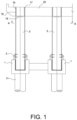
FIG. 1 is a schematic view of a structure formed by pier studs and a bent cap in the disclosure. -
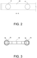
FIG. 2 is a schematic view ofFIG. 1 taken along line A-A. -
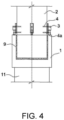
FIG. 3 is a schematic view of a bent cap mold base in the disclosure. -
FIG. 4 is a schematic front view of an auxiliary adjustment mechanism in the disclosure. -
FIG. 5 is a schematic top view of the auxiliary adjustment mechanism in the disclosure. -
FIG. 6 is a schematic view of a structure of a reaction frame in the disclosure. -
FIG. 7 is a schematic view of a matching structure between a pile top cup bearing platform and a prefabricated pier stud in the disclosure. - Reference numerals provided in the drawings include: pile top cup bearing platform 1,
prefabricated pier stud 2,reaction frame 3,steel rod 4, lower-layer steel rod 4a, horizontal universal beam 5, verticaluniversal beam 6, web reserved hole 7, lower-layer web reservedhole 7a, jack 8,consolidation surface 9,circular pad 10, pilefoundation 11,rectangular frame 12, limitingsteel ring 13, central steel pad 14, pier studpre-embedded steel bar 15,steel backing plate 16,grouting duct 17,steel bar sleeve 18, bent cappre-embedded sleeve 19, pier stud reservedhole 20, lower-layer pier stud reservedhole 20a, prefabricatedbent cap 22, pierstud metal bellow 23, andcup metal bellow 24. - With reference to
FIG. 1 andFIG. 2 , in this embodiment, pier studs are prefabricatedpier studs 2. A top portion of each of theprefabricated pier studs 2 is provided with protruding pier stud pre-embedded steel bars 15, and the pier stud pre-embedded steel bars 15 are evenly distributed into a circular ring shape on the top portion of each of theprefabricated pier studs 2 and form a pier stud pre-embedded steel bar ring with a radius r. A bent cap is a prefabricatedbent cap 22, and two ends of the prefabricatedbent cap 22 are respectively pre-embedded with bent cappre-embedded sleeves 19. Steel bellows may be adopted to be used as the bent cappre-embedded sleeves 19, and the use of the bellow structure may further enhance bonding and firmness between the pier stud pre-embedded steel bars 15 and the bent cappre-embedded sleeves 19.Vertical grouting ducts 17 are provided on a top portion of the prefabricatedbent cap 22 to communicate with the steelbar connection sleeves 19, and the bent cappre-embedded sleeves 19 on the two ends of the prefabricated bent cap are evenly distributed into a circular ring shape at each end to form a bent cap pre-embedded sleeve ring with a radius r. The bent cappre-embedded sleeves 19 in the bent cap pre-embedded sleeve ring correspond to the pier stud pre-embedded steel bars 15 in the pier stud pre-embedded steel bar ring one to one, such that the pier stud pre-embedded steel bars 15 may be inserted into the bent cappre-embedded sleeves 19 of corresponding positions for anchorage. - With reference to
FIG. 1 ,FIG. 2, and FIG. 3 , a bent cap mold base in this embodiment is configured as follows. - Limiting steel rings 13 are fixedly arranged at two ends of a
rectangular frame 12 of a steel structure, andsteel bar sleeves 18 are vertically arranged in the limiting steel rings 13. Thesteel bar sleeves 18 are evenly distributed into a circular ring shape in each limitingsteel ring 13 and form a steel bar sleeve ring with a radius r. A center-to-center distance of the steel bar sleeve rings at the two ends and a center-to-center distance of the bent cap pre-embedded sleeve rings at the two ends in the prefabricated bent cap are set to be identical. Positions of thesteel bar sleeves 18 in the steel bar sleeve ring are set to correspond to positions of the bent cappre-embedded sleeves 19 in the bent cap pre-embedded sleeve ring of the corresponding end one to one. - An installation method of a bent cap for mutually restraining adjacent pier studs in a prefabricated and assembled bridge provided by this embodiment is performed in constructed pile top cup bearing platforms 1 through the following steps.
- In step 1, the pile top cup bearing platforms 1 are formed on
pile foundations 11, theprefabricated pier studs 2 are placed in two adjacent pile top cup bearing platforms 1 through hoisting, and a center distance and a plane position between the twoprefabricated pier studs 2 are preliminarily adjusted. - In step 2: the cap bent mold base is hoisted on the top portions of the two
prefabricated pier studs 2, such that the pier stud pre-embedded steel bars 15 protruding from the top portions of the two prefabricated pier studs are correspondingly inserted into thesteel bar sleeves 18 at two ends of the bent cap mold base one by one. If the pier stud pre-embedded steel bars 15 in the two prefabricated pier studs and thesteel bar sleeves 18 at the two ends of the bent cap mold base are not aligned due to deviation, the prefabricated pier studs are lifted again by a crane, the center distance and/or the plane position between the two prefabricated pier studs are readjusted until the pier stud pre-embedded steel bars 15 in the two prefabricated pier studs are correspondingly inserted into the vertical sleeves at the two ends of the bent cap mold base one by one, such that the adjacent twoprefabricated pier studs 2 are limited in the bent cap mold base based on design needs. - In
step 3, heights and perpendicularity of the adjacent twoprefabricated pier studs 2 are adjusted to satisfy the design needs, and theprefabricated pier studs 2 are kept in a state which satisfies the design needs. - In
step 4, anchorage is performed between each of the pile top cup bearing platforms 1 and the correspondingprefabricated pier stud 2 to complete assembly of theprefabricated pier studs 2. - In step 5, the bent cap mold base is removed, the bent cap mold base is replaced with the bent cap,
steel backing plates 16 are placed between the top portions of the pier studs and the bent cap, and the pier stud pre-embedded steel bars 15 protruding from the top portions of the prefabricated pier studs are inserted into the bent cappre-embedded sleeves 19 pre-embedded in the bent cap one by one. - In
step 6, grouting is performed through thegrouting ducts 17 on the bent cap, anchorage is performed between theprefabricated pier studs 2 and the prefabricatedbent cap 22, and assembly of the prefabricatedbent cap 22 is thus completed. - In specific implementation,
step 3 further includes the following step. An auxiliary adjustment mechanism is arranged to adjust the height and perpendicularity of eachprefabricated pier stud 2. - A structure of the auxiliary adjustment mechanism shown in
FIG. 4 ,FIG. 5, and FIG. 6 is that: top support mechanisms are arranged between a top surface of each pile top cup bearing platform 1 and an outer side wall of eachprefabricated pier stud 2. The top support mechanisms are evenly distributed in at least three groups around the outer side wall of theprefabricated pier stud 2. Each group of the top support mechanisms may independently adjust a top support height thereof, and adjustment of the height and/or perpendicularity of thepier stud 2 is achieved through adjusting the top support height of the top support mechanisms of one group or plural groups. In this embodiment, four groups of the top support mechanisms distributed in a cross shape are provided, and the top support mechanisms at four positions may independently adjust their respective top support heights. According to spatial position information of theprefabricated pier stud 2 fed back by a total station, the top support heights of the top support mechanisms at the corresponding positions are adjusted, such that the pier stud may meet the perpendicularity and height requirements, and spatial position of the pier stud may be ensured to be accurate. - A structure of each of the top support mechanisms is that a jack 8 is provided on the top surface of each pile top cup bearing platform 1. A
reaction frame 3 having a horizontal support surface is provided on a corresponding position of the outer side wall of theprefabricated pier stud 2, and the jack 8 is supported between the top surface of the pile top cup bearing platform 1 and the support surface of thereaction frame 3. - As shown in
FIG. 6 , thereaction frame 3 is formed by a verticaluniversal beam 6 and a horizontal universal beam 5. The verticaluniversal beam 6 is attached to the outer side wall of theprefabricated pier stud 2 and is attached to the outer side wall of theprefabricated pier stud 2 through flange slabs separately disposed on two sides of a web of the verticaluniversal beam 6. One end of the horizontal universal beam 5 abuts against the web of the verticaluniversal beam 6 and is fixedly connected to the verticaluniversal beam 6, and a bottom surface of a lower flange slab in the horizontal universal beam 5 is the support surface of the reaction frame 5. - A fixed structure of the arranged
reaction frame 3 is that: a web reserved hole 7 is provided on the web of the verticaluniversal beam 6. As shown inFIG. 7 , pier stud reservedholes 20 are radially and horizontally arranged in theprefabricated pier stud 2. One end of asteel rod 4 is inserted into one of the pier stud reservedholes 20, and the other end of thesteel rod 4 penetrates through the web reserved hole 7 in the verticaluniversal beam 6 and is disposed on a top surface of an upper flange slab of the horizontal universal beam 5. - In specific implementation, in order to provide structural stability, the fixed structure of the
reaction frame 3 is further provided with a lower-layer fixed structure formed by: a lower-layer web reservedhole 7a, lower-layer pier stud reservedholes 20a, and a lower-layer steel rod 4a. The lower- layer fixed structure is located at a position that does not interfere with the horizontal universal beam 5. One end of the lower-layer steel rod 4a is inserted into one of the lower-layer pier stud reservedholes 20a of the prefabricated pier stud, and the other end of the lower-layer steel rod 4a is directly disposed in the lower-layer web reservedhole 7a in the verticaluniversal beam 6. - In addition, a center of the jack 8 should be as close as possible to the
prefabricated pier stud 2 when operating conditions are met, so as to reduce concrete damage when the steel rod is inserted into a mouth portion. Acircular pad 10 with a larger area than that of a bottom portion of the jack 8 may be placed on the bottom portion of the jack 8, so that a force may be evenly received. - In this embodiment, the step of performing anchorage between each of the pile top cup bearing platforms 1 and the corresponding
prefabricated pier stud 2 instep 4 further includes the following steps. - As shown in
FIG. 6 , a pierstud metal bellow 23 is pre-embedded on an outer circumferential surface of a lower section of theprefabricated pier stud 2, and a pier stud installation section whose outer circumferential surface is bellow-shaped is formed. In a cup mouth of each pile top cup bearing platform 1, acup metal bellow 24 is pre-embedded on a wall surface of a stud chamber, and a socket whose stud chamber wall surface is bellow-shaped. A central steel pad 14 with a protruding thickness of 20 mm is pre-embedded on a bottom surface of the stud chamber. The pier stud installation section is placed in the socket, an annular grouting chamber is formed between circumferential surfaces of each other, and a bottom plane grouting chamber is formed on a bottom surface. A high-strength grouting material is injected in the annular grouting chamber and the bottom plane grouting chamber to form aconsolidation surface 9 to achieve the anchorage between the pile top cup bearing platform 1 and the correspondingprefabricated pier stud 2. Both the pier stud metal bellow and the cup metal bellow adopt galvanized metal bellows. A thickness of the annular grouting chamber is 50 mm, and a thickness of the bottom plane grouting chamber is 20 mm. The high-strength grouting material is CGM-2 high-strength non-shrinkage grouting material, and a water-to-material ratio is 12% during mixing. - The installation method of the bent cap for mutually restraining the adjacent pier studs in the prefabricated and assembled bridge provided by the disclosure is verified in the assembly construction of the assembly-type pier studs and bent caps of the reconstruction and expansion project of the Tai'an to Zaozhuang (Lu-Sujie) section of the Jingtai Expressway. The success rate of one-time assembly construction of pier studs and bent caps reaches 100%, and the construction efficiency is significantly improved. Construction difficulty of difficult construction matching and low accuracy found in assembly construction of prefabricated circular pier studs and prefabricated bent caps is effectively prevented, and a good application prospect is provided in the same type of assembly construction.
Claims (8)
- An installation method of a bent cap for mutually restraining adjacent pier studs in a prefabricated and assembled bridge, wherein:the pier studs are prefabricated pier studs (2), a top portion of each of the prefabricated pier studs (2) is provided with pier stud pre-embedded steel bars (15), the pier stud pre-embedded steel bars (15) are evenly distributed into a circular ring shape on the top portion of each of the prefabricated pier studs (2) and form a pier stud pre-embedded steel bar ring with a radius r;the bent cap is a prefabricated bent cap (22), two ends of the prefabricated bent cap (22) are respectively pre-embedded with bent cap pre-embedded sleeves (19), vertical grouting ducts (17) are provided on a top portion of the prefabricated bent cap (22) and are in communication with the bent cap pre-embedded sleeves (19), the bent cap pre-embedded sleeves (19) on the two ends of the prefabricated bent cap are evenly distributed into a circular ring shape at each end to form a bent cap pre-embedded sleeve ring with a radius r; andthe bent cap pre-embedded sleeves (19) in the bent cap pre-embedded sleeve ring correspond to the pier stud pre-embedded steel bars (15) in the pier stud pre-embedded steel bar ring one to one, such that the pier stud pre-embedded steel bars (15) are able to be inserted into the bent cap pre-embedded sleeves (19) of corresponding positions for anchorage;characterised in that a bent cap mold base is configured as follows:fixedly arranging limiting steel rings (13) at two ends of a rectangular frame (12), and vertically arranging steel bar sleeves (18) in the limiting steel rings (13), wherein the steel bar sleeves (18) are evenly distributed into a circular ring shape in each of the limiting steel rings (13) and form a steel bar sleeve ring with a radius r; setting a center-to-center distance of the steel bar sleeve rings at the two ends and a center-to-center distance of the bent cap pre-embedded sleeve rings at the two ends in the prefabricated bent cap to be identical; and setting positions of the steel bar sleeves (18) in the steel bar sleeve ring to correspond to positions of the bent cap pre-embedded sleeves (19) in the bent cap pre-embedded sleeve ring of the corresponding end one to one;the installation method of the bent cap is performed in constructed pile top cup bearing platforms (1) through the following steps:step 1: through hoisting, placing the prefabricated pier studs (2) in two adjacent pile top cup bearing platforms (1), respectively, and preliminarily adjusting a center distance and a plane position between the two prefabricated pier studs (2);step 2: hoisting the cap bent mold base on the top portions of the two prefabricated pier studs (2), such that the pier stud pre-embedded steel bars (15) protruding from the top portions of the two prefabricated pier studs are correspondingly inserted into the steel bar sleeves (18) at two ends of the bent cap mold base one by one; and when the pier stud pre-embedded steel bars (15) in the two prefabricated pier studs and the steel bar sleeves (18) at the two ends of the bent cap mold base are not aligned due to deviation, lifting the prefabricated pier studs again by a crane and readjusting the center distance and/or the plane position between the two prefabricated pier studs until the pier stud pre-embedded steel bars (15) in the two prefabricated pier studs are correspondingly inserted into the vertical steel bar sleeves at the two ends of the bent cap mold base one by one, such that the adjacent two prefabricated pier studs (2) are limited in the bent cap mold base;step 3: adjusting heights and perpendicularity of the adjacent two prefabricated pier studs (2) to satisfy design needs, and keeping the prefabricated pier studs (2) in a state which satisfies the design needs;step 4: performing anchorage between each of the pile top cup bearing platforms (1) and the corresponding prefabricated pier stud (2) to complete assembly of the prefabricated pier studs (2);step 5: removing the bent cap mold base, replacing the bent cap mold base with the bent cap, and inserting the pier stud pre-embedded steel bars (15) protruding from the top portions of the prefabricated pier studs into the bent cap pre-embedded sleeves (19) pre-embedded in the bent cap one by one; andstep 6: performing grouting through the grouting ducts (17) on the bent cap, performing anchorage between the prefabricated pier studs (2) and the prefabricated bent cap (22), and completing assembly of the prefabricated bent cap (22).
- The installation method of the bent cap for mutually restraining the adjacent pier studs in the prefabricated and assembled bridge according to claim 1, characterized in that:
in step 3, arranging an auxiliary adjustment mechanism to adjust the height and perpendicularity of each prefabricated pier stud (2), wherein a structure of the auxiliary adjustment mechanism is that top support mechanisms are arranged between a top surface of each pile top cup bearing platform (1) and an outer side wall of each prefabricated pier stud (2), the top support mechanisms are evenly distributed in at least three groups around the outer side wall of the prefabricated pier stud (2), each group of the top support mechanisms is able to independently adjust a top support height thereof, and adjustment of the height and/or the perpendicularity of the prefabricated pier stud is achieved through adjusting the top support height of the top support mechanisms of one group or plural groups. - The installation method of the bent cap for mutually restraining the adjacent pier studs in the prefabricated and assembled bridge according to claim 2, characterized in that: a structure of each of the top support mechanisms is that a jack (8) is provided on the top surface of each pile top cup bearing platform (1), a reaction frame (3) having a horizontal support surface is provided on a corresponding position of the outer side wall of each prefabricated pier stud (2), and the jack (8) is supported between the top surface of the pile top cup bearing platform (1) and the support surface of the reaction frame (3).
- The installation method of the bent cap for mutually restraining the adjacent pier studs in the prefabricated and assembled bridge according to claim 3, characterized in that: the reaction frame (3) is formed by a vertical universal beam (6) and a horizontal universal beam (5), the vertical universal beam (6) is attached to the outer side wall of the prefabricated pier stud (2) and is attached to the outer side wall of the prefabricated pier stud (2) through flange slabs separately disposed on two sides of a web of the vertical universal beam (6), one end of the horizontal universal beam (5) abuts against the web of the vertical universal beam (6) and is fixedly connected to the vertical universal beam (6), and a bottom surface of a lower flange slab in the horizontal universal beam (5) is the support surface of the reaction frame (3).
- The installation method of the bent cap for mutually restraining the adjacent pier studs in the prefabricated and assembled bridge according to claim 4, characterized in that: a fixed structure of the reaction frame (3) is that a web reserved hole (7) is provided on the web of the vertical universal beam (6), pier stud reserved holes (20) are radially and horizontally arranged in each prefabricated pier stud (2), one end of a steel rod (4) is inserted into one of the pier stud reserved holes (20), and the other end of the steel rod penetrates through the web reserved hole (7) in the vertical universal beam (6) and is disposed on a top surface of an upper flange slab of the horizontal universal beam (5).
- The installation method of the bent cap for mutually restraining the adjacent pier studs in the prefabricated and assembled bridge according to claim 5, characterized in that: the fixed structure of the reaction frame (3) is further provided with a lower-layer fixed structure formed by a lower-layer web reserved hole (7a), lower-layer pier stud reserved holes (20a), and a lower-layer steel rod (4a), wherein the lower- layer fixed structure is located at a position that does not interfere with the horizontal universal beam (5), one end of the lower-layer steel rod (4a) is inserted into one of the lower-layer pier stud reserved holes (20a) of the prefabricated pier stud, and the other end of the lower-layer steel rod is directly disposed in the lower-layer web reserved hole (7a) in the vertical universal beam (6).
- The installation method of the bent cap for mutually restraining the adjacent pier studs in the prefabricated and assembled bridge according to claim 1, characterized in that:
performing anchorage between each of the pile top cup bearing platforms (1) and the corresponding prefabricated pier stud (2) in step 4 comprises the following steps:pre-embedding a pier stud metal bellow (23) on an outer circumferential surface of a lower section of the prefabricated pier stud (2), and forming a pier stud installation section having an outer circumferential surface being bellow-shaped;pre-embedding a cup metal bellow (24) on a wall surface of a stud chamber in a cup mouth of each pile top cup bearing platform (1), forming a socket having a stud chamber wall surface being bellow-shaped, and pre-embedding a central steel pad (14) on a bottom surface of the stud chamber; andplacing the pier stud installation section in the socket, forming an annular grouting chamber between circumferential surfaces of each other, forming a bottom plane grouting chamber on a bottom surface, and injecting a high-strength grouting material in the annular grouting chamber and the bottom plane grouting chamber to achieve the anchorage between the pile top cup bearing platform (1) and the corresponding prefabricated pier stud (2). - The installation method of the bent cap for mutually restraining the adjacent pier studs in the prefabricated and assembled bridge according to claim 7, characterized in that: both the pier stud metal bellow (23) and the cup metal bellow adopt galvanized metal bellows, a thickness of the annular grouting chamber is 50 mm, and a thickness of the bottom plane grouting chamber is 20 mm.
Applications Claiming Priority (2)
| Application Number | Priority Date | Filing Date | Title |
|---|---|---|---|
| CN202010261163.0A CN111305082B (en) | 2020-04-03 | 2020-04-03 | Cover beam installation method for mutual restraint between adjacent piers and columns in prefabricated bridges |
| PCT/CN2020/136425 WO2021196739A1 (en) | 2020-04-03 | 2020-12-15 | Cap beam mounting method achieving mutual constraint of adjacent pier columns in prefabricated bridge |
Publications (3)
| Publication Number | Publication Date |
|---|---|
| EP3933110A1 EP3933110A1 (en) | 2022-01-05 |
| EP3933110A4 EP3933110A4 (en) | 2022-07-27 |
| EP3933110B1 true EP3933110B1 (en) | 2024-02-28 |
Family
ID=71159156
Family Applications (1)
| Application Number | Title | Priority Date | Filing Date |
|---|---|---|---|
| EP20924982.0A Active EP3933110B1 (en) | 2020-04-03 | 2020-12-15 | Cap beam mounting method achieving mutual constraint of adjacent pier columns in prefabricated bridge |
Country Status (4)
| Country | Link |
|---|---|
| US (1) | US11708671B2 (en) |
| EP (1) | EP3933110B1 (en) |
| CN (1) | CN111305082B (en) |
| WO (1) | WO2021196739A1 (en) |
Families Citing this family (28)
| Publication number | Priority date | Publication date | Assignee | Title |
|---|---|---|---|---|
| CN109853363B (en) * | 2018-12-18 | 2024-07-02 | 中交第二公路勘察设计研究院有限公司 | Connecting structure of pipe pier and bearing platform and construction method |
| CN111305082B (en) * | 2020-04-03 | 2021-04-06 | 中铁四局集团有限公司 | Cover beam installation method for mutual restraint between adjacent piers and columns in prefabricated bridges |
| CN111809526B (en) * | 2020-07-30 | 2021-07-16 | 兰州理工大学 | Prefabricated bridge double-column pier system and construction method with recoverable function after earthquake |
| CN112030724B (en) * | 2020-08-10 | 2021-11-09 | 山东高速建设管理集团有限公司 | Bidirectional socket type prefabricated assembly type pier and construction method thereof |
| CN111996906B (en) * | 2020-09-21 | 2021-07-13 | 山东鲁桥建设有限公司 | Efficient construction method of assembled pier |
| CN112095453A (en) * | 2020-09-24 | 2020-12-18 | 安徽省交通规划设计研究总院股份有限公司 | Multi-shear-resistant prefabricated pier beam connecting device and implementation method thereof |
| CN113005915A (en) * | 2021-03-19 | 2021-06-22 | 中交四公局第三工程有限公司 | Positioning device and positioning method for embedded steel bars at top of assembled bridge tied beam |
| CN113373815A (en) * | 2021-06-22 | 2021-09-10 | 中铁十九局集团第一工程有限公司 | Construction method for on-site wet joint of prefabricated bent cap |
| CN114164764B (en) * | 2021-11-10 | 2023-11-21 | 中交第四航务工程局有限公司 | Construction method of high-filling bridge bearing platform structure |
| CN114635349A (en) * | 2021-12-06 | 2022-06-17 | 中交第二公路勘察设计研究院有限公司 | Lightweight fabricated bridge piers suitable for non-strong earthquake areas |
| CN114032795B (en) * | 2021-12-14 | 2023-12-22 | 安徽省路港工程有限责任公司 | Bracket capping beam method for integrally utilizing overpass during reconstruction and expansion of expressway |
| CN114319080B (en) * | 2022-01-17 | 2024-06-04 | 宁波市高等级公路建设管理中心 | High strength bent cap structure based on UHPC shell |
| CN115030160B (en) * | 2022-05-17 | 2023-10-27 | 中铁四局集团有限公司 | A method and positioning system for inserting and driving steel pipe piles |
| CN114892992B (en) * | 2022-06-24 | 2024-04-02 | 北京博大新元房地产开发有限公司 | Precision control device for embedded bars of assembled wall conversion layer and construction process |
| CN115595882A (en) * | 2022-09-24 | 2023-01-13 | 南昌大学(Cn) | A Rapid Construction Method of Prestressed Concrete Cap Beam of Wide Bridge |
| CN115726270B (en) * | 2022-11-02 | 2025-11-21 | 上海城投公路投资(集团)有限公司 | Construction method of bridge large-span gate pier structure |
| CN115748802A (en) * | 2022-11-17 | 2023-03-07 | 国网湖北省电力有限公司宜昌供电公司 | Prefabricated concrete buttress structure of GIS (gas insulated switchgear) equipment of transformer substation and digital assembly method thereof |
| CN115949091A (en) * | 2022-11-21 | 2023-04-11 | 山东大学 | A pile foundation structure and method suitable for pile foundation underpinning of stacked tunnels |
| CN115898118B (en) * | 2022-12-05 | 2024-06-18 | 北京工业大学 | Prefabricated assembly type railway platform canopy structure in medium and high intensity area and construction method |
| CN115807394B (en) * | 2022-12-09 | 2025-09-09 | 保利长大工程有限公司 | Capping beam construction process |
| CN116356693A (en) * | 2023-01-07 | 2023-06-30 | 中铁大桥局武汉桥梁特种技术有限公司 | A construction method for assembly-type cover-beam connection and a cover-beam connection structure |
| CN116591043B (en) * | 2023-04-19 | 2024-04-26 | 中铁一局集团市政环保工程有限公司 | Construction method of pier stud embedded bars on splicing surface of assembled bridge bearing platform |
| CN116357058A (en) * | 2023-05-09 | 2023-06-30 | 中国十九冶集团有限公司 | Steel construction lateral wall working in face platform mounting structure |
| CN117569216A (en) * | 2023-12-28 | 2024-02-20 | 中交一公局第七工程有限公司 | A method for controlling the verticality of a lifting frame |
| CN117646384B (en) * | 2024-01-25 | 2024-10-18 | 湖南省交通规划勘察设计院有限公司 | A non-capping assembled bridge pier and construction method for conventional areas |
| CN117661432B (en) * | 2024-01-30 | 2024-04-16 | 中建八局第二建设有限公司 | Pier structure anchored by high-strength steel bars |
| CN118228371B (en) * | 2024-05-27 | 2024-07-16 | 贵州省公路工程集团有限公司 | Intelligent design method and system for thin-wall hollow pier capping beam bracket |
| CN119434084B (en) * | 2024-12-10 | 2025-09-12 | 福州大学 | FRP composite reinforced recycled concrete prefabricated assembly pier-foundation socket joint and construction method |
Family Cites Families (18)
| Publication number | Priority date | Publication date | Assignee | Title |
|---|---|---|---|---|
| US4910940A (en) * | 1977-08-29 | 1990-03-27 | Grady Ii Clyde C | Modular structural arrays |
| US5586417A (en) * | 1994-11-23 | 1996-12-24 | Henderson; Allan P. | Tensionless pier foundation |
| US6571717B2 (en) * | 1998-04-08 | 2003-06-03 | Einar Svensson | Y-shaped support structure for elevated rail-vehicle guideway |
| US7618217B2 (en) * | 2003-12-15 | 2009-11-17 | Henderson Allan P | Post-tension pile anchor foundation and method therefor |
| US7546656B2 (en) * | 2005-08-16 | 2009-06-16 | Daewoo Engineering & Construction Co., Ltd | Method of installing prefabricated, segment concrete filled tube members |
| US8006339B1 (en) * | 2009-03-27 | 2011-08-30 | Jeffery W Bennett | Prefabricated articulating pier cap |
| KR100950715B1 (en) * | 2009-10-26 | 2010-03-31 | (주)대우건설 | Method for constructing precast coping for bridge |
| KR20110103000A (en) * | 2010-03-12 | 2011-09-20 | 고려대학교 산학협력단 | Steel composite hollow precast pier joint structure using concrete filling unit and construction method |
| KR101203980B1 (en) * | 2010-09-30 | 2012-11-22 | 주식회사 아앤시티 | upper structure of bridge |
| KR101351829B1 (en) | 2012-03-08 | 2014-01-16 | 충남대학교산학협력단 | Pier construction method using pile and precast capbeam |
| CN105803925B (en) * | 2016-03-17 | 2017-05-17 | 浙江大学 | Quick connection method for prefabricated steel pipe constraint type steel concrete pier columns and cover beam |
| CN106049259A (en) * | 2016-06-16 | 2016-10-26 | 安徽省交通规划设计研究总院股份有限公司 | Bridge integrally-assembled pier and construction method |
| CN106677056A (en) * | 2017-02-16 | 2017-05-17 | 上海市城市建设设计研究总院(集团)有限公司 | Prefabricated double-column vase bridge pier and assembling construction method thereof |
| CN107100078B (en) * | 2017-05-19 | 2019-01-08 | 中国五冶集团有限公司 | A kind of packaged type bridges Precast Pier Columns component installation method |
| CN208280001U (en) * | 2018-02-05 | 2018-12-25 | 横琴共轭科技有限公司 | A kind of assembled pier of regular reinforcement and finish rolling deformed bar hybrid reinforcement |
| CN110004821A (en) * | 2019-05-23 | 2019-07-12 | 福州大学 | A kind of prefabricated bridge pier connection structure and its construction method |
| CN110629664A (en) * | 2019-10-24 | 2019-12-31 | 北京市市政工程设计研究总院有限公司 | A prefabricated assembled UHPC lattice bridge pier column structure and its construction method |
| CN111305082B (en) | 2020-04-03 | 2021-04-06 | 中铁四局集团有限公司 | Cover beam installation method for mutual restraint between adjacent piers and columns in prefabricated bridges |
-
2020
- 2020-04-03 CN CN202010261163.0A patent/CN111305082B/en active Active
- 2020-12-15 WO PCT/CN2020/136425 patent/WO2021196739A1/en not_active Ceased
- 2020-12-15 EP EP20924982.0A patent/EP3933110B1/en active Active
- 2020-12-15 US US17/416,526 patent/US11708671B2/en active Active
Also Published As
| Publication number | Publication date |
|---|---|
| US20220220677A1 (en) | 2022-07-14 |
| WO2021196739A1 (en) | 2021-10-07 |
| EP3933110A1 (en) | 2022-01-05 |
| US11708671B2 (en) | 2023-07-25 |
| CN111305082A (en) | 2020-06-19 |
| CN111305082B (en) | 2021-04-06 |
| EP3933110A4 (en) | 2022-07-27 |
Similar Documents
| Publication | Publication Date | Title |
|---|---|---|
| US11708671B2 (en) | Installation method of bent cap for mutually restraining adjacent pier studs in prefabricated and assembled bridge | |
| CN107653781A (en) | Big steel pipe truss and construction method for bent cap cast-in-place construction | |
| KR101916744B1 (en) | Upper structure of bridge with improved stiffness, and Bridge construction method using it | |
| CN110644371A (en) | Prefabricated cover beam installation method and system | |
| CN217652349U (en) | Temporary supporting system for post-cast strip template of basement roof | |
| CN107326816A (en) | A kind of method for improving of prefabricated pinner and bridge | |
| JP3237751U (en) | Concrete placing platform | |
| CN218893398U (en) | Tower crane foundation structure for high-altitude tower column construction | |
| CN113373815A (en) | Construction method for on-site wet joint of prefabricated bent cap | |
| CN113293790B (en) | Pre-leveling tower foundation and leveling construction method thereof | |
| CN114635446A (en) | Installation method of large steel cylinder annular foundation | |
| CN210767913U (en) | Structure for temporarily supporting precast concrete outer wall | |
| CN218708498U (en) | Vertical non-adhesive steel bar integral hoisting and mounting device | |
| CN214883824U (en) | Pre-leveling tower foundation | |
| CN113026766A (en) | Supporting structure for foundation pit excavation and using method | |
| CN215594609U (en) | Anchor plate and stiff column fixing structure in stiff structure | |
| CN212025900U (en) | Auxiliary adjusting device in installation of assembled bridge pier stud | |
| CN215857280U (en) | High mound river-crossing bridge penetrating bar cantilever supporting system | |
| CN118563822A (en) | High pile beam slab structure and construction method | |
| CN110565830A (en) | construction method for mounting assembled type coupling beam damper in advance | |
| JP4395090B2 (en) | Replacement method for multi-function bearings on existing bridges | |
| CN215594920U (en) | Back-jacking type overhanging structure formwork supporting system | |
| CN213296364U (en) | Connecting piece and supporting beam steel bar assembly for cast-in-place reinforced concrete foundation pit inner support sectional construction | |
| CN112376918A (en) | Method for quickly positioning precast reinforced concrete beam | |
| CN222314006U (en) | Base plate prestressing force trades and props structure |
Legal Events
| Date | Code | Title | Description |
|---|---|---|---|
| STAA | Information on the status of an ep patent application or granted ep patent |
Free format text: STATUS: UNKNOWN |
|
| STAA | Information on the status of an ep patent application or granted ep patent |
Free format text: STATUS: THE INTERNATIONAL PUBLICATION HAS BEEN MADE |
|
| PUAI | Public reference made under article 153(3) epc to a published international application that has entered the european phase |
Free format text: ORIGINAL CODE: 0009012 |
|
| STAA | Information on the status of an ep patent application or granted ep patent |
Free format text: STATUS: THE APPLICATION HAS BEEN PUBLISHED |
|
| AK | Designated contracting states |
Kind code of ref document: A1 Designated state(s): AL AT BE BG CH CY CZ DE DK EE ES FI FR GB GR HR HU IE IS IT LI LT LU LV MC MK MT NL NO PL PT RO RS SE SI SK SM TR |
|
| STAA | Information on the status of an ep patent application or granted ep patent |
Free format text: STATUS: REQUEST FOR EXAMINATION WAS MADE |
|
| 17P | Request for examination filed |
Effective date: 20220407 |
|
| RBV | Designated contracting states (corrected) |
Designated state(s): AL AT BE BG CH CY CZ DE DK EE ES FI FR GB GR HR HU IE IS IT LI LT LU LV MC MK MT NL NO PL PT RO RS SE SI SK SM TR |
|
| A4 | Supplementary search report drawn up and despatched |
Effective date: 20220629 |
|
| RIC1 | Information provided on ipc code assigned before grant |
Ipc: E01D 19/02 20060101ALI20220623BHEP Ipc: E01D 19/00 20060101ALI20220623BHEP Ipc: E01D 21/00 20060101AFI20220623BHEP |
|
| RIN1 | Information on inventor provided before grant (corrected) |
Inventor name: ZHANG, SHOUFENG Inventor name: XING, BIAO Inventor name: XU, JINMIAO Inventor name: REN, HAO Inventor name: XU, TAO Inventor name: ZHU, ZHENYE Inventor name: FANG, SHISHENG Inventor name: XU, XINGHUO Inventor name: JIN, LIJUN Inventor name: YAO, DACHUANG Inventor name: WANG, JIAQING |
|
| DAV | Request for validation of the european patent (deleted) | ||
| DAX | Request for extension of the european patent (deleted) | ||
| GRAP | Despatch of communication of intention to grant a patent |
Free format text: ORIGINAL CODE: EPIDOSNIGR1 |
|
| STAA | Information on the status of an ep patent application or granted ep patent |
Free format text: STATUS: GRANT OF PATENT IS INTENDED |
|
| INTG | Intention to grant announced |
Effective date: 20230719 |
|
| GRAS | Grant fee paid |
Free format text: ORIGINAL CODE: EPIDOSNIGR3 |
|
| GRAJ | Information related to disapproval of communication of intention to grant by the applicant or resumption of examination proceedings by the epo deleted |
Free format text: ORIGINAL CODE: EPIDOSDIGR1 |
|
| GRAL | Information related to payment of fee for publishing/printing deleted |
Free format text: ORIGINAL CODE: EPIDOSDIGR3 |
|
| STAA | Information on the status of an ep patent application or granted ep patent |
Free format text: STATUS: REQUEST FOR EXAMINATION WAS MADE |
|
| GRAP | Despatch of communication of intention to grant a patent |
Free format text: ORIGINAL CODE: EPIDOSNIGR1 |
|
| STAA | Information on the status of an ep patent application or granted ep patent |
Free format text: STATUS: GRANT OF PATENT IS INTENDED |
|
| INTC | Intention to grant announced (deleted) | ||
| INTG | Intention to grant announced |
Effective date: 20231214 |
|
| GRAA | (expected) grant |
Free format text: ORIGINAL CODE: 0009210 |
|
| STAA | Information on the status of an ep patent application or granted ep patent |
Free format text: STATUS: THE PATENT HAS BEEN GRANTED |
|
| AK | Designated contracting states |
Kind code of ref document: B1 Designated state(s): AL AT BE BG CH CY CZ DE DK EE ES FI FR GB GR HR HU IE IS IT LI LT LU LV MC MK MT NL NO PL PT RO RS SE SI SK SM TR |
|
| REG | Reference to a national code |
Ref country code: GB Ref legal event code: FG4D |
|
| REG | Reference to a national code |
Ref country code: CH Ref legal event code: EP |
|
| REG | Reference to a national code |
Ref country code: DE Ref legal event code: R096 Ref document number: 602020026614 Country of ref document: DE |
|
| REG | Reference to a national code |
Ref country code: IE Ref legal event code: FG4D |
|
| REG | Reference to a national code |
Ref country code: LT Ref legal event code: MG9D |
|
| PG25 | Lapsed in a contracting state [announced via postgrant information from national office to epo] |
Ref country code: IS Free format text: LAPSE BECAUSE OF FAILURE TO SUBMIT A TRANSLATION OF THE DESCRIPTION OR TO PAY THE FEE WITHIN THE PRESCRIBED TIME-LIMIT Effective date: 20240628 |
|
| REG | Reference to a national code |
Ref country code: NL Ref legal event code: MP Effective date: 20240228 |
|
| PG25 | Lapsed in a contracting state [announced via postgrant information from national office to epo] |
Ref country code: LT Free format text: LAPSE BECAUSE OF FAILURE TO SUBMIT A TRANSLATION OF THE DESCRIPTION OR TO PAY THE FEE WITHIN THE PRESCRIBED TIME-LIMIT Effective date: 20240228 |
|
| PG25 | Lapsed in a contracting state [announced via postgrant information from national office to epo] |
Ref country code: GR Free format text: LAPSE BECAUSE OF FAILURE TO SUBMIT A TRANSLATION OF THE DESCRIPTION OR TO PAY THE FEE WITHIN THE PRESCRIBED TIME-LIMIT Effective date: 20240529 |
|
| PG25 | Lapsed in a contracting state [announced via postgrant information from national office to epo] |
Ref country code: HR Free format text: LAPSE BECAUSE OF FAILURE TO SUBMIT A TRANSLATION OF THE DESCRIPTION OR TO PAY THE FEE WITHIN THE PRESCRIBED TIME-LIMIT Effective date: 20240228 Ref country code: RS Free format text: LAPSE BECAUSE OF FAILURE TO SUBMIT A TRANSLATION OF THE DESCRIPTION OR TO PAY THE FEE WITHIN THE PRESCRIBED TIME-LIMIT Effective date: 20240528 Ref country code: NL Free format text: LAPSE BECAUSE OF FAILURE TO SUBMIT A TRANSLATION OF THE DESCRIPTION OR TO PAY THE FEE WITHIN THE PRESCRIBED TIME-LIMIT Effective date: 20240228 |
|
| PG25 | Lapsed in a contracting state [announced via postgrant information from national office to epo] |
Ref country code: ES Free format text: LAPSE BECAUSE OF FAILURE TO SUBMIT A TRANSLATION OF THE DESCRIPTION OR TO PAY THE FEE WITHIN THE PRESCRIBED TIME-LIMIT Effective date: 20240228 |
|
| PG25 | Lapsed in a contracting state [announced via postgrant information from national office to epo] |
Ref country code: RS Free format text: LAPSE BECAUSE OF FAILURE TO SUBMIT A TRANSLATION OF THE DESCRIPTION OR TO PAY THE FEE WITHIN THE PRESCRIBED TIME-LIMIT Effective date: 20240528 Ref country code: NO Free format text: LAPSE BECAUSE OF FAILURE TO SUBMIT A TRANSLATION OF THE DESCRIPTION OR TO PAY THE FEE WITHIN THE PRESCRIBED TIME-LIMIT Effective date: 20240528 Ref country code: NL Free format text: LAPSE BECAUSE OF FAILURE TO SUBMIT A TRANSLATION OF THE DESCRIPTION OR TO PAY THE FEE WITHIN THE PRESCRIBED TIME-LIMIT Effective date: 20240228 Ref country code: LT Free format text: LAPSE BECAUSE OF FAILURE TO SUBMIT A TRANSLATION OF THE DESCRIPTION OR TO PAY THE FEE WITHIN THE PRESCRIBED TIME-LIMIT Effective date: 20240228 Ref country code: IS Free format text: LAPSE BECAUSE OF FAILURE TO SUBMIT A TRANSLATION OF THE DESCRIPTION OR TO PAY THE FEE WITHIN THE PRESCRIBED TIME-LIMIT Effective date: 20240628 Ref country code: HR Free format text: LAPSE BECAUSE OF FAILURE TO SUBMIT A TRANSLATION OF THE DESCRIPTION OR TO PAY THE FEE WITHIN THE PRESCRIBED TIME-LIMIT Effective date: 20240228 Ref country code: GR Free format text: LAPSE BECAUSE OF FAILURE TO SUBMIT A TRANSLATION OF THE DESCRIPTION OR TO PAY THE FEE WITHIN THE PRESCRIBED TIME-LIMIT Effective date: 20240529 Ref country code: FI Free format text: LAPSE BECAUSE OF FAILURE TO SUBMIT A TRANSLATION OF THE DESCRIPTION OR TO PAY THE FEE WITHIN THE PRESCRIBED TIME-LIMIT Effective date: 20240228 Ref country code: ES Free format text: LAPSE BECAUSE OF FAILURE TO SUBMIT A TRANSLATION OF THE DESCRIPTION OR TO PAY THE FEE WITHIN THE PRESCRIBED TIME-LIMIT Effective date: 20240228 Ref country code: BG Free format text: LAPSE BECAUSE OF FAILURE TO SUBMIT A TRANSLATION OF THE DESCRIPTION OR TO PAY THE FEE WITHIN THE PRESCRIBED TIME-LIMIT Effective date: 20240228 |
|
| PG25 | Lapsed in a contracting state [announced via postgrant information from national office to epo] |
Ref country code: PT Free format text: LAPSE BECAUSE OF FAILURE TO SUBMIT A TRANSLATION OF THE DESCRIPTION OR TO PAY THE FEE WITHIN THE PRESCRIBED TIME-LIMIT Effective date: 20240628 Ref country code: PL Free format text: LAPSE BECAUSE OF FAILURE TO SUBMIT A TRANSLATION OF THE DESCRIPTION OR TO PAY THE FEE WITHIN THE PRESCRIBED TIME-LIMIT Effective date: 20240228 |
|
| REG | Reference to a national code |
Ref country code: AT Ref legal event code: MK05 Ref document number: 1661346 Country of ref document: AT Kind code of ref document: T Effective date: 20240228 |
|
| PG25 | Lapsed in a contracting state [announced via postgrant information from national office to epo] |
Ref country code: SE Free format text: LAPSE BECAUSE OF FAILURE TO SUBMIT A TRANSLATION OF THE DESCRIPTION OR TO PAY THE FEE WITHIN THE PRESCRIBED TIME-LIMIT Effective date: 20240228 Ref country code: PT Free format text: LAPSE BECAUSE OF FAILURE TO SUBMIT A TRANSLATION OF THE DESCRIPTION OR TO PAY THE FEE WITHIN THE PRESCRIBED TIME-LIMIT Effective date: 20240628 Ref country code: PL Free format text: LAPSE BECAUSE OF FAILURE TO SUBMIT A TRANSLATION OF THE DESCRIPTION OR TO PAY THE FEE WITHIN THE PRESCRIBED TIME-LIMIT Effective date: 20240228 Ref country code: LV Free format text: LAPSE BECAUSE OF FAILURE TO SUBMIT A TRANSLATION OF THE DESCRIPTION OR TO PAY THE FEE WITHIN THE PRESCRIBED TIME-LIMIT Effective date: 20240228 |
|
| PG25 | Lapsed in a contracting state [announced via postgrant information from national office to epo] |
Ref country code: DK Free format text: LAPSE BECAUSE OF FAILURE TO SUBMIT A TRANSLATION OF THE DESCRIPTION OR TO PAY THE FEE WITHIN THE PRESCRIBED TIME-LIMIT Effective date: 20240228 |
|
| PG25 | Lapsed in a contracting state [announced via postgrant information from national office to epo] |
Ref country code: SM Free format text: LAPSE BECAUSE OF FAILURE TO SUBMIT A TRANSLATION OF THE DESCRIPTION OR TO PAY THE FEE WITHIN THE PRESCRIBED TIME-LIMIT Effective date: 20240228 |
|
| PG25 | Lapsed in a contracting state [announced via postgrant information from national office to epo] |
Ref country code: CZ Free format text: LAPSE BECAUSE OF FAILURE TO SUBMIT A TRANSLATION OF THE DESCRIPTION OR TO PAY THE FEE WITHIN THE PRESCRIBED TIME-LIMIT Effective date: 20240228 Ref country code: EE Free format text: LAPSE BECAUSE OF FAILURE TO SUBMIT A TRANSLATION OF THE DESCRIPTION OR TO PAY THE FEE WITHIN THE PRESCRIBED TIME-LIMIT Effective date: 20240228 |
|
| PG25 | Lapsed in a contracting state [announced via postgrant information from national office to epo] |
Ref country code: AT Free format text: LAPSE BECAUSE OF FAILURE TO SUBMIT A TRANSLATION OF THE DESCRIPTION OR TO PAY THE FEE WITHIN THE PRESCRIBED TIME-LIMIT Effective date: 20240228 |
|
| PG25 | Lapsed in a contracting state [announced via postgrant information from national office to epo] |
Ref country code: SK Free format text: LAPSE BECAUSE OF FAILURE TO SUBMIT A TRANSLATION OF THE DESCRIPTION OR TO PAY THE FEE WITHIN THE PRESCRIBED TIME-LIMIT Effective date: 20240228 |
|
| PG25 | Lapsed in a contracting state [announced via postgrant information from national office to epo] |
Ref country code: SM Free format text: LAPSE BECAUSE OF FAILURE TO SUBMIT A TRANSLATION OF THE DESCRIPTION OR TO PAY THE FEE WITHIN THE PRESCRIBED TIME-LIMIT Effective date: 20240228 Ref country code: SK Free format text: LAPSE BECAUSE OF FAILURE TO SUBMIT A TRANSLATION OF THE DESCRIPTION OR TO PAY THE FEE WITHIN THE PRESCRIBED TIME-LIMIT Effective date: 20240228 Ref country code: RO Free format text: LAPSE BECAUSE OF FAILURE TO SUBMIT A TRANSLATION OF THE DESCRIPTION OR TO PAY THE FEE WITHIN THE PRESCRIBED TIME-LIMIT Effective date: 20240228 Ref country code: EE Free format text: LAPSE BECAUSE OF FAILURE TO SUBMIT A TRANSLATION OF THE DESCRIPTION OR TO PAY THE FEE WITHIN THE PRESCRIBED TIME-LIMIT Effective date: 20240228 Ref country code: DK Free format text: LAPSE BECAUSE OF FAILURE TO SUBMIT A TRANSLATION OF THE DESCRIPTION OR TO PAY THE FEE WITHIN THE PRESCRIBED TIME-LIMIT Effective date: 20240228 Ref country code: CZ Free format text: LAPSE BECAUSE OF FAILURE TO SUBMIT A TRANSLATION OF THE DESCRIPTION OR TO PAY THE FEE WITHIN THE PRESCRIBED TIME-LIMIT Effective date: 20240228 Ref country code: AT Free format text: LAPSE BECAUSE OF FAILURE TO SUBMIT A TRANSLATION OF THE DESCRIPTION OR TO PAY THE FEE WITHIN THE PRESCRIBED TIME-LIMIT Effective date: 20240228 |
|
| REG | Reference to a national code |
Ref country code: DE Ref legal event code: R097 Ref document number: 602020026614 Country of ref document: DE |
|
| PG25 | Lapsed in a contracting state [announced via postgrant information from national office to epo] |
Ref country code: IT Free format text: LAPSE BECAUSE OF FAILURE TO SUBMIT A TRANSLATION OF THE DESCRIPTION OR TO PAY THE FEE WITHIN THE PRESCRIBED TIME-LIMIT Effective date: 20240228 |
|
| PG25 | Lapsed in a contracting state [announced via postgrant information from national office to epo] |
Ref country code: IT Free format text: LAPSE BECAUSE OF FAILURE TO SUBMIT A TRANSLATION OF THE DESCRIPTION OR TO PAY THE FEE WITHIN THE PRESCRIBED TIME-LIMIT Effective date: 20240228 |
|
| PLBE | No opposition filed within time limit |
Free format text: ORIGINAL CODE: 0009261 |
|
| STAA | Information on the status of an ep patent application or granted ep patent |
Free format text: STATUS: NO OPPOSITION FILED WITHIN TIME LIMIT |
|
| 26N | No opposition filed |
Effective date: 20241129 |
|
| PG25 | Lapsed in a contracting state [announced via postgrant information from national office to epo] |
Ref country code: SI Free format text: LAPSE BECAUSE OF FAILURE TO SUBMIT A TRANSLATION OF THE DESCRIPTION OR TO PAY THE FEE WITHIN THE PRESCRIBED TIME-LIMIT Effective date: 20240228 |
|
| PG25 | Lapsed in a contracting state [announced via postgrant information from national office to epo] |
Ref country code: MC Free format text: LAPSE BECAUSE OF FAILURE TO SUBMIT A TRANSLATION OF THE DESCRIPTION OR TO PAY THE FEE WITHIN THE PRESCRIBED TIME-LIMIT Effective date: 20240228 |
|
| REG | Reference to a national code |
Ref country code: CH Ref legal event code: PL |
|
| PG25 | Lapsed in a contracting state [announced via postgrant information from national office to epo] |
Ref country code: LU Free format text: LAPSE BECAUSE OF NON-PAYMENT OF DUE FEES Effective date: 20241215 |
|
| GBPC | Gb: european patent ceased through non-payment of renewal fee |
Effective date: 20241215 |
|
| REG | Reference to a national code |
Ref country code: BE Ref legal event code: MM Effective date: 20241231 |
|
| PG25 | Lapsed in a contracting state [announced via postgrant information from national office to epo] |
Ref country code: BE Free format text: LAPSE BECAUSE OF NON-PAYMENT OF DUE FEES Effective date: 20241231 Ref country code: GB Free format text: LAPSE BECAUSE OF NON-PAYMENT OF DUE FEES Effective date: 20241215 |
|
| PG25 | Lapsed in a contracting state [announced via postgrant information from national office to epo] |
Ref country code: FR Free format text: LAPSE BECAUSE OF NON-PAYMENT OF DUE FEES Effective date: 20241231 |
|
| PG25 | Lapsed in a contracting state [announced via postgrant information from national office to epo] |
Ref country code: CH Free format text: LAPSE BECAUSE OF NON-PAYMENT OF DUE FEES Effective date: 20241231 |
|
| PG25 | Lapsed in a contracting state [announced via postgrant information from national office to epo] |
Ref country code: IE Free format text: LAPSE BECAUSE OF NON-PAYMENT OF DUE FEES Effective date: 20241215 |
|
| PGFP | Annual fee paid to national office [announced via postgrant information from national office to epo] |
Ref country code: DE Payment date: 20251222 Year of fee payment: 6 |
|
| PG25 | Lapsed in a contracting state [announced via postgrant information from national office to epo] |
Ref country code: CY Free format text: LAPSE BECAUSE OF FAILURE TO SUBMIT A TRANSLATION OF THE DESCRIPTION OR TO PAY THE FEE WITHIN THE PRESCRIBED TIME-LIMIT Effective date: 20240228 |