EP3933013A2 - Quenchbehälteranordnung für hydroprozessreaktor - Google Patents
Quenchbehälteranordnung für hydroprozessreaktor Download PDFInfo
- Publication number
- EP3933013A2 EP3933013A2 EP21180472.9A EP21180472A EP3933013A2 EP 3933013 A2 EP3933013 A2 EP 3933013A2 EP 21180472 A EP21180472 A EP 21180472A EP 3933013 A2 EP3933013 A2 EP 3933013A2
- Authority
- EP
- European Patent Office
- Prior art keywords
- quench
- gas
- swirling
- box assembly
- liquid
- Prior art date
- Legal status (The legal status is an assumption and is not a legal conclusion. Google has not performed a legal analysis and makes no representation as to the accuracy of the status listed.)
- Pending
Links
Images

Classifications
-
- B—PERFORMING OPERATIONS; TRANSPORTING
- B01—PHYSICAL OR CHEMICAL PROCESSES OR APPARATUS IN GENERAL
- B01F—MIXING, e.g. DISSOLVING, EMULSIFYING OR DISPERSING
- B01F25/00—Flow mixers; Mixers for falling materials, e.g. solid particles
- B01F25/40—Static mixers
- B01F25/42—Static mixers in which the mixing is affected by moving the components jointly in changing directions, e.g. in tubes provided with baffles or obstructions
- B01F25/43—Mixing tubes, e.g. wherein the material is moved in a radial or partly reversed direction
- B01F25/431—Straight mixing tubes with baffles or obstructions that do not cause substantial pressure drop; Baffles therefor
- B01F25/4312—Straight mixing tubes with baffles or obstructions that do not cause substantial pressure drop; Baffles therefor having different kinds of baffles, e.g. plates alternating with screens
-
- C—CHEMISTRY; METALLURGY
- C10—PETROLEUM, GAS OR COKE INDUSTRIES; TECHNICAL GASES CONTAINING CARBON MONOXIDE; FUELS; LUBRICANTS; PEAT
- C10G—CRACKING HYDROCARBON OILS; PRODUCTION OF LIQUID HYDROCARBON MIXTURES, e.g. BY DESTRUCTIVE HYDROGENATION, OLIGOMERISATION, POLYMERISATION; RECOVERY OF HYDROCARBON OILS FROM OIL-SHALE, OIL-SAND, OR GASES; REFINING MIXTURES MAINLY CONSISTING OF HYDROCARBONS; REFORMING OF NAPHTHA; MINERAL WAXES
- C10G49/00—Treatment of hydrocarbon oils, in the presence of hydrogen or hydrogen-generating compounds, not provided for in a single one of groups C10G45/02, C10G45/32, C10G45/44, C10G45/58 or C10G47/00
- C10G49/002—Apparatus for fixed bed hydrotreatment processes
-
- B—PERFORMING OPERATIONS; TRANSPORTING
- B01—PHYSICAL OR CHEMICAL PROCESSES OR APPARATUS IN GENERAL
- B01F—MIXING, e.g. DISSOLVING, EMULSIFYING OR DISPERSING
- B01F23/00—Mixing according to the phases to be mixed, e.g. dispersing or emulsifying
- B01F23/20—Mixing gases with liquids
- B01F23/23—Mixing gases with liquids by introducing gases into liquid media, e.g. for producing aerated liquids
- B01F23/232—Mixing gases with liquids by introducing gases into liquid media, e.g. for producing aerated liquids using flow-mixing means for introducing the gases, e.g. baffles
-
- B—PERFORMING OPERATIONS; TRANSPORTING
- B01—PHYSICAL OR CHEMICAL PROCESSES OR APPARATUS IN GENERAL
- B01J—CHEMICAL OR PHYSICAL PROCESSES, e.g. CATALYSIS OR COLLOID CHEMISTRY; THEIR RELEVANT APPARATUS
- B01J19/00—Chemical, physical or physico-chemical processes in general; Their relevant apparatus
- B01J19/0006—Controlling or regulating processes
- B01J19/0013—Controlling the temperature of the process
-
- B—PERFORMING OPERATIONS; TRANSPORTING
- B01—PHYSICAL OR CHEMICAL PROCESSES OR APPARATUS IN GENERAL
- B01J—CHEMICAL OR PHYSICAL PROCESSES, e.g. CATALYSIS OR COLLOID CHEMISTRY; THEIR RELEVANT APPARATUS
- B01J19/00—Chemical, physical or physico-chemical processes in general; Their relevant apparatus
- B01J19/0053—Details of the reactor
- B01J19/006—Baffles
-
- B—PERFORMING OPERATIONS; TRANSPORTING
- B01—PHYSICAL OR CHEMICAL PROCESSES OR APPARATUS IN GENERAL
- B01J—CHEMICAL OR PHYSICAL PROCESSES, e.g. CATALYSIS OR COLLOID CHEMISTRY; THEIR RELEVANT APPARATUS
- B01J8/00—Chemical or physical processes in general, conducted in the presence of fluids and solid particles; Apparatus for such processes
- B01J8/02—Chemical or physical processes in general, conducted in the presence of fluids and solid particles; Apparatus for such processes with stationary particles, e.g. in fixed beds
- B01J8/04—Chemical or physical processes in general, conducted in the presence of fluids and solid particles; Apparatus for such processes with stationary particles, e.g. in fixed beds the fluid passing successively through two or more beds
- B01J8/0446—Chemical or physical processes in general, conducted in the presence of fluids and solid particles; Apparatus for such processes with stationary particles, e.g. in fixed beds the fluid passing successively through two or more beds the flow within the beds being predominantly vertical
- B01J8/0449—Chemical or physical processes in general, conducted in the presence of fluids and solid particles; Apparatus for such processes with stationary particles, e.g. in fixed beds the fluid passing successively through two or more beds the flow within the beds being predominantly vertical in two or more cylindrical beds
- B01J8/0453—Chemical or physical processes in general, conducted in the presence of fluids and solid particles; Apparatus for such processes with stationary particles, e.g. in fixed beds the fluid passing successively through two or more beds the flow within the beds being predominantly vertical in two or more cylindrical beds the beds being superimposed one above the other
-
- B—PERFORMING OPERATIONS; TRANSPORTING
- B01—PHYSICAL OR CHEMICAL PROCESSES OR APPARATUS IN GENERAL
- B01J—CHEMICAL OR PHYSICAL PROCESSES, e.g. CATALYSIS OR COLLOID CHEMISTRY; THEIR RELEVANT APPARATUS
- B01J8/00—Chemical or physical processes in general, conducted in the presence of fluids and solid particles; Apparatus for such processes
- B01J8/02—Chemical or physical processes in general, conducted in the presence of fluids and solid particles; Apparatus for such processes with stationary particles, e.g. in fixed beds
- B01J8/04—Chemical or physical processes in general, conducted in the presence of fluids and solid particles; Apparatus for such processes with stationary particles, e.g. in fixed beds the fluid passing successively through two or more beds
- B01J8/0496—Heating or cooling the reactor
-
- C—CHEMISTRY; METALLURGY
- C10—PETROLEUM, GAS OR COKE INDUSTRIES; TECHNICAL GASES CONTAINING CARBON MONOXIDE; FUELS; LUBRICANTS; PEAT
- C10G—CRACKING HYDROCARBON OILS; PRODUCTION OF LIQUID HYDROCARBON MIXTURES, e.g. BY DESTRUCTIVE HYDROGENATION, OLIGOMERISATION, POLYMERISATION; RECOVERY OF HYDROCARBON OILS FROM OIL-SHALE, OIL-SAND, OR GASES; REFINING MIXTURES MAINLY CONSISTING OF HYDROCARBONS; REFORMING OF NAPHTHA; MINERAL WAXES
- C10G45/00—Refining of hydrocarbon oils using hydrogen or hydrogen-generating compounds
-
- C—CHEMISTRY; METALLURGY
- C10—PETROLEUM, GAS OR COKE INDUSTRIES; TECHNICAL GASES CONTAINING CARBON MONOXIDE; FUELS; LUBRICANTS; PEAT
- C10G—CRACKING HYDROCARBON OILS; PRODUCTION OF LIQUID HYDROCARBON MIXTURES, e.g. BY DESTRUCTIVE HYDROGENATION, OLIGOMERISATION, POLYMERISATION; RECOVERY OF HYDROCARBON OILS FROM OIL-SHALE, OIL-SAND, OR GASES; REFINING MIXTURES MAINLY CONSISTING OF HYDROCARBONS; REFORMING OF NAPHTHA; MINERAL WAXES
- C10G47/00—Cracking of hydrocarbon oils, in the presence of hydrogen or hydrogen- generating compounds, to obtain lower boiling fractions
-
- B—PERFORMING OPERATIONS; TRANSPORTING
- B01—PHYSICAL OR CHEMICAL PROCESSES OR APPARATUS IN GENERAL
- B01F—MIXING, e.g. DISSOLVING, EMULSIFYING OR DISPERSING
- B01F25/00—Flow mixers; Mixers for falling materials, e.g. solid particles
- B01F2025/91—Direction of flow or arrangement of feed and discharge openings
- B01F2025/913—Vortex flow, i.e. flow spiraling in a tangential direction and moving in an axial direction
-
- B—PERFORMING OPERATIONS; TRANSPORTING
- B01—PHYSICAL OR CHEMICAL PROCESSES OR APPARATUS IN GENERAL
- B01F—MIXING, e.g. DISSOLVING, EMULSIFYING OR DISPERSING
- B01F25/00—Flow mixers; Mixers for falling materials, e.g. solid particles
- B01F2025/91—Direction of flow or arrangement of feed and discharge openings
- B01F2025/916—Turbulent flow, i.e. every point of the flow moves in a random direction and intermixes
-
- B—PERFORMING OPERATIONS; TRANSPORTING
- B01—PHYSICAL OR CHEMICAL PROCESSES OR APPARATUS IN GENERAL
- B01F—MIXING, e.g. DISSOLVING, EMULSIFYING OR DISPERSING
- B01F2215/00—Auxiliary or complementary information in relation with mixing
- B01F2215/04—Technical information in relation with mixing
- B01F2215/0413—Numerical information
- B01F2215/0418—Geometrical information
- B01F2215/0422—Numerical values of angles
-
- B—PERFORMING OPERATIONS; TRANSPORTING
- B01—PHYSICAL OR CHEMICAL PROCESSES OR APPARATUS IN GENERAL
- B01J—CHEMICAL OR PHYSICAL PROCESSES, e.g. CATALYSIS OR COLLOID CHEMISTRY; THEIR RELEVANT APPARATUS
- B01J2208/00—Processes carried out in the presence of solid particles; Reactors therefor
- B01J2208/00008—Controlling the process
- B01J2208/00017—Controlling the temperature
- B01J2208/00327—Controlling the temperature by direct heat exchange
- B01J2208/00336—Controlling the temperature by direct heat exchange adding a temperature modifying medium to the reactants
- B01J2208/00353—Non-cryogenic fluids
- B01J2208/00371—Non-cryogenic fluids gaseous
-
- B—PERFORMING OPERATIONS; TRANSPORTING
- B01—PHYSICAL OR CHEMICAL PROCESSES OR APPARATUS IN GENERAL
- B01J—CHEMICAL OR PHYSICAL PROCESSES, e.g. CATALYSIS OR COLLOID CHEMISTRY; THEIR RELEVANT APPARATUS
- B01J2208/00—Processes carried out in the presence of solid particles; Reactors therefor
- B01J2208/00796—Details of the reactor or of the particulate material
- B01J2208/00823—Mixing elements
- B01J2208/00831—Stationary elements
- B01J2208/00849—Stationary elements outside the bed, e.g. baffles
-
- B—PERFORMING OPERATIONS; TRANSPORTING
- B01—PHYSICAL OR CHEMICAL PROCESSES OR APPARATUS IN GENERAL
- B01J—CHEMICAL OR PHYSICAL PROCESSES, e.g. CATALYSIS OR COLLOID CHEMISTRY; THEIR RELEVANT APPARATUS
- B01J2208/00—Processes carried out in the presence of solid particles; Reactors therefor
- B01J2208/00796—Details of the reactor or of the particulate material
- B01J2208/00893—Feeding means for the reactants
-
- B—PERFORMING OPERATIONS; TRANSPORTING
- B01—PHYSICAL OR CHEMICAL PROCESSES OR APPARATUS IN GENERAL
- B01J—CHEMICAL OR PHYSICAL PROCESSES, e.g. CATALYSIS OR COLLOID CHEMISTRY; THEIR RELEVANT APPARATUS
- B01J2208/00—Processes carried out in the presence of solid particles; Reactors therefor
- B01J2208/00796—Details of the reactor or of the particulate material
- B01J2208/00938—Flow distribution elements
-
- B—PERFORMING OPERATIONS; TRANSPORTING
- B01—PHYSICAL OR CHEMICAL PROCESSES OR APPARATUS IN GENERAL
- B01J—CHEMICAL OR PHYSICAL PROCESSES, e.g. CATALYSIS OR COLLOID CHEMISTRY; THEIR RELEVANT APPARATUS
- B01J2219/00—Chemical, physical or physico-chemical processes in general; Their relevant apparatus
- B01J2219/00049—Controlling or regulating processes
- B01J2219/00051—Controlling the temperature
- B01J2219/00121—Controlling the temperature by direct heating or cooling
- B01J2219/00123—Controlling the temperature by direct heating or cooling adding a temperature modifying medium to the reactants
-
- B—PERFORMING OPERATIONS; TRANSPORTING
- B01—PHYSICAL OR CHEMICAL PROCESSES OR APPARATUS IN GENERAL
- B01J—CHEMICAL OR PHYSICAL PROCESSES, e.g. CATALYSIS OR COLLOID CHEMISTRY; THEIR RELEVANT APPARATUS
- B01J2219/00—Chemical, physical or physico-chemical processes in general; Their relevant apparatus
- B01J2219/00761—Details of the reactor
- B01J2219/00763—Baffles
- B01J2219/00765—Baffles attached to the reactor wall
- B01J2219/0077—Baffles attached to the reactor wall inclined
Definitions
- the present invention covers Quench box assembly comprising quench pipe and quench box for down-flow, three-phase fixed bed hydro-processing reactor is disclosed.
- the quench pipe is in the form of ring having aperture while quench box consists of swirling section and a mixing chamber.
- EP0471117A1 covers the quench box assembly having improved mixing efficiency comprises a series of mixing zones: quench fluid inlet zone; quench box mixing zone; a jet stirred mixing zone; and a distributor zone.
- quench fluid inlet zone quench fluid is introduced to fluid from the catalytic bed above.
- reaction fluid and quench fluid enter the quench mixing zone through the central opening (16) and no means to mix theses fluids thoroughly is provided.
- plurality of pipes (22) for introduction of quench gas and process fluid into jet stirred mixing zone may result into non-uniform temperature from different pipes.
- US7112312B2 covers the compact quench box design for a multi-bed, mixed-phase co-current downflow fixed-bed reactor has a quench pipe manifold and nozzle assembly, a collection tray, a mixing chamber, and a single final distributor tray.
- the quench pipe manifold and nozzle assembly is an annular ring pipe having nozzles arising there from.
- the multiple ramps (50) and mixing chamber (36) for reaction fluid and quench fluid may lead to different temperature in ramps (50) and mixing chamber (36) leading to uneven temperature after the quench-box assembly.
- the quench pipe is in the form of a ring with apertures for quench gas flow.
- the quench box consists of a swirling section and a mixing chamber. It provides higher interfacial area and flow path for heat transfer between quench gas and hot reactor effluent.
- the swirling motion in the swirling section provides better contacting.
- the weir in the mixing section creates turbulence and helps to attain equilibrium temperature for entire fluid as it is the only passage for fluid flow.
- the baffle on the plate calms liquid down and provide higher residence time and turbulence for the incoming fluid resulting in higher heat transfer rate.
- the perforated plate being open from all the sides allowing the liquid to flow uniformly from all directions thus providing uniform distribution on the distributor tray. Hence, eliminates the requirement of rough liquid distributor before the distribution tray.
- Quench box assembly comprising quench pipe and quench box for down-flow, three-phase fixed bed hydro-processing reactor.
- quench pipe is in the form of ring having aperture while quench box consists of swirling section and a mixing chamber.
- the object of this invention is that the aforesaid quench box helps to achieve the equilibrium temperature to the hot-reactor effluent and the quench gas entering from the quench pipe.
- FIG. 1 A commonly used vapor liquid downward flow fixed bed reactor is shown in Figure-1 ( prior art ).
- the gas-liquid mixture enters through a feed pipe 101 and through inlet diffuser 102 gets distributed on the distributer tray 104, having distribution units 105 through catalyst bed 106 installed inside the reactor 103.
- the hot effluent from the catalyst bed 106 and the quench gas from quench pipe 107 gets mixed in the quench box 108 and flows to the catalyst bed 106 /outlet 109.
- Figure-1 is a schematic view of an exemplary configuration of a prior art hydro-processing reactor.
- the quench pipe is in the form of a ring with apertures for quench gas flow.
- the quench box consists of a swirling section and a mixing chamber. It provides higher interfacial area and flow path for heat transfer between quench gas and hot reactor effluent.
- the swirling motion in the swirling section provides better contacting.
- the weir in the mixing section creates turbulence and helps to attain equilibrium temperature for entire fluid as it is the only passage for fluid flow.
- the baffle on the plate calms liquid down and provide higher residence time and turbulence for the incoming fluid resulting in higher heat transfer rate.
- the perforated plate being open from all the sides allowing the liquid to flow uniformly from all directions thus providing uniform distribution on the distributor tray. Hence, eliminates the requirement of rough liquid distributor before the distribution tray.
- the present invention provides a Quench box assembly for hydro-processing reactors comprising:
- the present invention provides a Quench box assembly, wherein the quench pipe ( 201 ) is located around the swirling section ( 203 ) of the quench box and the swirling section ( 203 ) is having inclined baffles ( 204 ) to provide swirling motion to the incoming gas-liquid mixture.
- the present invention provides a Quench box assembly, wherein the gas-liquid mixture from the swirling section ( 203 ) impinges on the plate ( 205 ) and splash around in the mixing chamber ( 206 ) and flows downward through the weir ( 207 ).
- the present invention provides a Quench box assembly, wherein gas-liquid mixture travels from the weir ( 207 ) to the perforated plate ( 208 ) which is solid at the centre ( 209 ) below the weir outlet and having aperture ( 210 ) and a baffle in the form of the ring ( 211 ).
- the present invention provides a Quench box assembly, wherein the perforated plate ( 208 ) is open from the sides allowing the liquid to flow uniformly from all directions thus providing uniform distribution on the distributor tray ( 212 ).
- the present invention provides a Quench box assembly, wherein swirling section ( 203 ) is having baffles ( 204 ) inclined at an angle preferably between 30 to 60°.
- the present invention provides a process for mixing quench gas and vapor-liquid effluent by Quench box assembly, said process comprising:
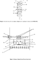
- FIG. 2 design of proposed Quench box is given in Figure-2.
- the quench pipe and quench box is shown in Figure 2 .
- the quench pipe 201 is in the form of circular ring having apertures 202 on its surface and is located around the swirling section 203 of the quench box.
- the swirling section is having inclined baffles 204 to provide swirling motion to the incoming gas-liquid mixture.
- the gas-liquid mixture from the swirling section impinges on the plate 205 and splash around in the mixing chamber 206 and flows downward through the weir 207.
- the perforated plate 208 which is solid at the centre 209 below the weir outlet and having aperture 210 and a baffle in the form of the ring 211.
- the perforated plate 208 is open from the sides allowing the liquid to flow uniformly from all directions thus providing uniform distribution on the distributor tray 212.
- the present invention covers Quench box assembly comprising quench pipe and quench box for mixing hot reactor effluent and cold quench gas for down-flow, three-phase fixed bed hydro-processing reactor is disclosed.
- Figure 2 along with Figure 3 describe Quench box and process in accordance with the present invention.
- Figure 3 shows the Fluid motion in accordance with the present invention.
- the quench pipe (201) is in the form of ring having aperture while quench box consists of swirling section (203) and a mixing chamber (206) and it is located around the swirling section of quench box.
- the swirling section is having baffles (204) inclined at an angle preferably between 30 to 60° to provide swirling motion to the incoming fluid.
- the swirling motion provides better contacting between the flowing fluids.
- the fluid from the swirling section (203) travels to the mixing chamber (206) and impinges on the flat surface and splash around providing the residence time in the mixing chamber (206) for attaining equilibrium temperature.
- gas-liquid mixture flows downward through the weir (207) located at the centre of mixing chamber on the perforated plate (208).
- the plate is having aperture (210) on its surface except the area at the centre (209) where the incoming liquid from the weir impinges the plate.
- a circular baffle is provided on the plate for creating turbulence and increase the residence time of fluid on the plate.
- the plate is having open sides and fluid travels in all direction downward on the distributor plate (212). The design is compact and eliminates the requirement of rough liquid distributor before the distribution tray. It may be noted there is only one passage for the fluid flow thus entire fluid stream will have same temperature.
- the swirling section (203) with inclined baffles (204) splits the incoming stream into different parts providing high gas liquid interfacial area between the quench-gas and incoming liquid. This will result in better contacting and achieving equilibrium temperature. Furthermore, the turbulence created by the swirling action (203) increases the heat transfer rate thus requiring the smaller reactor volume to attain equilibrium temperature. Furthermore, as there is only one passage for the fluid to pass through the mixing chamber (206) with high velocity, it creates high turbulence inside the mixing chamber resulting in no dead zones inside it. Due to high velocities in mixing chamber there will be no accumulation of solids/fines in the quench box. Hence, the proposed design shows better resistance to fouling.
- the circular baffle on the perforated plate (208) further increases the residence time of the fluid in the quench box leading to achieve equilibrium temperature.
- the perforated plate (208) being open from all the sides allowing the liquid to flow uniformly from all directions thus providing uniform distribution on the distributor tray (212). Hence, eliminates the requirement of rough liquid distributor before the distribution tray.
Landscapes
- Chemical & Material Sciences (AREA)
- Chemical Kinetics & Catalysis (AREA)
- Organic Chemistry (AREA)
- Oil, Petroleum & Natural Gas (AREA)
- Engineering & Computer Science (AREA)
- General Chemical & Material Sciences (AREA)
- Dispersion Chemistry (AREA)
- Devices And Processes Conducted In The Presence Of Fluids And Solid Particles (AREA)
Applications Claiming Priority (1)
| Application Number | Priority Date | Filing Date | Title |
|---|---|---|---|
| IN202021028524 | 2020-07-04 |
Publications (2)
| Publication Number | Publication Date |
|---|---|
| EP3933013A2 true EP3933013A2 (de) | 2022-01-05 |
| EP3933013A3 EP3933013A3 (de) | 2022-01-12 |
Family
ID=76532121
Family Applications (1)
| Application Number | Title | Priority Date | Filing Date |
|---|---|---|---|
| EP21180472.9A Pending EP3933013A3 (de) | 2020-07-04 | 2021-06-18 | Quenchbehälteranordnung für hydroprozessreaktor |
Country Status (3)
| Country | Link |
|---|---|
| US (1) | US11498038B2 (de) |
| EP (1) | EP3933013A3 (de) |
| SA (1) | SA121420827B1 (de) |
Cited By (1)
| Publication number | Priority date | Publication date | Assignee | Title |
|---|---|---|---|---|
| CN115301160A (zh) * | 2022-07-26 | 2022-11-08 | 中国石油化工股份有限公司 | 抽吸式旋流混合分布器及气液混合分布设备 |
Families Citing this family (1)
| Publication number | Priority date | Publication date | Assignee | Title |
|---|---|---|---|---|
| CN114950173B (zh) * | 2022-05-09 | 2023-06-16 | 中国石油化工股份有限公司 | 微气泡冷氢传质机构和催化加氢反应器 |
Citations (2)
| Publication number | Priority date | Publication date | Assignee | Title |
|---|---|---|---|---|
| EP0471117A1 (de) | 1988-12-14 | 1992-02-19 | Exxon Research And Engineering Company | Quench Gehäuseanordnung |
| US7112312B2 (en) | 2001-04-02 | 2006-09-26 | Tai-Sheng Chou | Quench box for a multi-bed, mixed-phase cocurrent downflow fixed-bed reactor |
Family Cites Families (4)
| Publication number | Priority date | Publication date | Assignee | Title |
|---|---|---|---|---|
| US3787189A (en) * | 1971-12-17 | 1974-01-22 | Standard Oil Co | Apparatus for mixing fluids in a vessel between beds of solids |
| WO2013092886A1 (en) * | 2011-12-22 | 2013-06-27 | Shell Internationale Research Maatschappij B.V. | Distributor device for a multiple-bed downflow reactor |
| US9321023B2 (en) * | 2013-06-28 | 2016-04-26 | Uop Llc | Fluid mixing and distribution device and method for multibed reactors |
| US10668442B1 (en) * | 2019-02-07 | 2020-06-02 | Uop Llc | Hydroprocessing reactor internals having reduced height |
-
2021
- 2021-06-18 EP EP21180472.9A patent/EP3933013A3/de active Pending
- 2021-06-23 SA SA121420827A patent/SA121420827B1/ar unknown
- 2021-06-30 US US17/364,182 patent/US11498038B2/en active Active
Patent Citations (2)
| Publication number | Priority date | Publication date | Assignee | Title |
|---|---|---|---|---|
| EP0471117A1 (de) | 1988-12-14 | 1992-02-19 | Exxon Research And Engineering Company | Quench Gehäuseanordnung |
| US7112312B2 (en) | 2001-04-02 | 2006-09-26 | Tai-Sheng Chou | Quench box for a multi-bed, mixed-phase cocurrent downflow fixed-bed reactor |
Cited By (1)
| Publication number | Priority date | Publication date | Assignee | Title |
|---|---|---|---|---|
| CN115301160A (zh) * | 2022-07-26 | 2022-11-08 | 中国石油化工股份有限公司 | 抽吸式旋流混合分布器及气液混合分布设备 |
Also Published As
| Publication number | Publication date |
|---|---|
| EP3933013A3 (de) | 2022-01-12 |
| US20220001341A1 (en) | 2022-01-06 |
| US11498038B2 (en) | 2022-11-15 |
| SA121420827B1 (ar) | 2024-01-24 |
Similar Documents
| Publication | Publication Date | Title |
|---|---|---|
| US6508459B1 (en) | Distribution apparatus having bubble caps with riser vanes | |
| US6881387B1 (en) | Reactor distribution apparatus and quench zone mixing apparatus | |
| EP2767333B1 (de) | Mischvorrichtung mit Tangentialeinsätzen für Zweiphasen-Parallelstrombehälter | |
| US6180068B1 (en) | Interbed gas-liquid mixing system for cocurrent downflow reactors | |
| AU699855B2 (en) | Distributor device for multiple-bed downflow reactors | |
| US7074372B2 (en) | Multiphase mixing device with improved quench injection for inducing rotational flow | |
| JP2004237283A (ja) | 多段ガス導入を伴う改良された多相混合装置 | |
| US11498038B2 (en) | Quench-box assembly for hydroprocessing reactors | |
| EP3658271B1 (de) | Vorrichtung zur flüssigkeitskontaktierung in einem abstromgefäss | |
| EP0716881A1 (de) | Verteilervorrichtung für abwärtsfliessende mehrstufige Reaktoren | |
| EP3658270B1 (de) | Vorrichtung zur fluidkontaktierung in einem ablaufbehälter | |
| EP3747536A1 (de) | Einlassdiffusor für festbettreaktoren | |
| US4792229A (en) | Device for mixing disperse streams before they enter a catalyst bed | |
| EP3658267B1 (de) | Verfahren zur fluidkontaktierung in einem abwärtsflussbehälter | |
| CN111344056B (zh) | 用于在下流式容器中进行流体接触的方法和设备 | |
| CN116322969B (zh) | 具有减小高度的加氢处理反应器内构件 | |
| US20240181416A1 (en) | Quench mixing device for multi-bed downflow reactors | |
| CN111246935B (zh) | 带有纵向开口的混合和分布装置 | |
| MXPA01004052A (en) | Reactor distribution apparatus and quench zone mixing apparatus |
Legal Events
| Date | Code | Title | Description |
|---|---|---|---|
| PUAI | Public reference made under article 153(3) epc to a published international application that has entered the european phase |
Free format text: ORIGINAL CODE: 0009012 |
|
| STAA | Information on the status of an ep patent application or granted ep patent |
Free format text: STATUS: THE APPLICATION HAS BEEN PUBLISHED |
|
| PUAL | Search report despatched |
Free format text: ORIGINAL CODE: 0009013 |
|
| AK | Designated contracting states |
Kind code of ref document: A2 Designated state(s): AL AT BE BG CH CY CZ DE DK EE ES FI FR GB GR HR HU IE IS IT LI LT LU LV MC MK MT NL NO PL PT RO RS SE SI SK SM TR |
|
| AK | Designated contracting states |
Kind code of ref document: A3 Designated state(s): AL AT BE BG CH CY CZ DE DK EE ES FI FR GB GR HR HU IE IS IT LI LT LU LV MC MK MT NL NO PL PT RO RS SE SI SK SM TR |
|
| RIC1 | Information provided on ipc code assigned before grant |
Ipc: B01J 8/04 20060101ALI20211203BHEP Ipc: C10G 49/00 20060101AFI20211203BHEP |
|
| STAA | Information on the status of an ep patent application or granted ep patent |
Free format text: STATUS: REQUEST FOR EXAMINATION WAS MADE |
|
| 17P | Request for examination filed |
Effective date: 20220613 |
|
| RBV | Designated contracting states (corrected) |
Designated state(s): AL AT BE BG CH CY CZ DE DK EE ES FI FR GB GR HR HU IE IS IT LI LT LU LV MC MK MT NL NO PL PT RO RS SE SI SK SM TR |
|
| P01 | Opt-out of the competence of the unified patent court (upc) registered |
Effective date: 20230712 |