EP3932853A1 - Container sterilization device, content filling system, container sterilization method, and content filling method - Google Patents
Container sterilization device, content filling system, container sterilization method, and content filling method Download PDFInfo
- Publication number
- EP3932853A1 EP3932853A1 EP20766467.3A EP20766467A EP3932853A1 EP 3932853 A1 EP3932853 A1 EP 3932853A1 EP 20766467 A EP20766467 A EP 20766467A EP 3932853 A1 EP3932853 A1 EP 3932853A1
- Authority
- EP
- European Patent Office
- Prior art keywords
- sterilizing
- bottle
- container
- agent
- nozzle
- Prior art date
- Legal status (The legal status is an assumption and is not a legal conclusion. Google has not performed a legal analysis and makes no representation as to the accuracy of the status listed.)
- Pending
Links
Images






Classifications
-
- B—PERFORMING OPERATIONS; TRANSPORTING
- B67—OPENING, CLOSING OR CLEANING BOTTLES, JARS OR SIMILAR CONTAINERS; LIQUID HANDLING
- B67C—CLEANING, FILLING WITH LIQUIDS OR SEMILIQUIDS, OR EMPTYING, OF BOTTLES, JARS, CANS, CASKS, BARRELS, OR SIMILAR CONTAINERS, NOT OTHERWISE PROVIDED FOR; FUNNELS
- B67C7/00—Concurrent cleaning, filling, and closing of bottles; Processes or devices for at least two of these operations
- B67C7/0073—Sterilising, aseptic filling and closing
-
- A—HUMAN NECESSITIES
- A61—MEDICAL OR VETERINARY SCIENCE; HYGIENE
- A61L—METHODS OR APPARATUS FOR STERILISING MATERIALS OR OBJECTS IN GENERAL; DISINFECTION, STERILISATION OR DEODORISATION OF AIR; CHEMICAL ASPECTS OF BANDAGES, DRESSINGS, ABSORBENT PADS OR SURGICAL ARTICLES; MATERIALS FOR BANDAGES, DRESSINGS, ABSORBENT PADS OR SURGICAL ARTICLES
- A61L2/00—Disinfection or sterilisation of materials or objects, in general; Accessories therefor
- A61L2/16—Disinfection or sterilisation of materials or objects, in general; Accessories therefor using chemical substances
- A61L2/22—Phase substances, e.g. smokes or aerosols
-
- B—PERFORMING OPERATIONS; TRANSPORTING
- B29—WORKING OF PLASTICS; WORKING OF SUBSTANCES IN A PLASTIC STATE IN GENERAL
- B29C—SHAPING OR JOINING OF PLASTICS; SHAPING OF MATERIAL IN A PLASTIC STATE, NOT OTHERWISE PROVIDED FOR; AFTER-TREATMENT OF THE SHAPED PRODUCTS, e.g. REPAIRING
- B29C49/00—Blow-moulding, i.e. blowing a preform or parison to a desired shape within a mould; Apparatus therefor
- B29C49/08—Biaxial stretching during blow-moulding
-
- B—PERFORMING OPERATIONS; TRANSPORTING
- B29—WORKING OF PLASTICS; WORKING OF SUBSTANCES IN A PLASTIC STATE IN GENERAL
- B29C—SHAPING OR JOINING OF PLASTICS; SHAPING OF MATERIAL IN A PLASTIC STATE, NOT OTHERWISE PROVIDED FOR; AFTER-TREATMENT OF THE SHAPED PRODUCTS, e.g. REPAIRING
- B29C49/00—Blow-moulding, i.e. blowing a preform or parison to a desired shape within a mould; Apparatus therefor
- B29C49/42—Component parts, details or accessories; Auxiliary operations
- B29C49/4273—Auxiliary operations after the blow-moulding operation not otherwise provided for
-
- B—PERFORMING OPERATIONS; TRANSPORTING
- B67—OPENING, CLOSING OR CLEANING BOTTLES, JARS OR SIMILAR CONTAINERS; LIQUID HANDLING
- B67C—CLEANING, FILLING WITH LIQUIDS OR SEMILIQUIDS, OR EMPTYING, OF BOTTLES, JARS, CANS, CASKS, BARRELS, OR SIMILAR CONTAINERS, NOT OTHERWISE PROVIDED FOR; FUNNELS
- B67C7/00—Concurrent cleaning, filling, and closing of bottles; Processes or devices for at least two of these operations
- B67C7/0006—Conveying; Synchronising
- B67C7/0013—Synchronising
-
- B—PERFORMING OPERATIONS; TRANSPORTING
- B67—OPENING, CLOSING OR CLEANING BOTTLES, JARS OR SIMILAR CONTAINERS; LIQUID HANDLING
- B67C—CLEANING, FILLING WITH LIQUIDS OR SEMILIQUIDS, OR EMPTYING, OF BOTTLES, JARS, CANS, CASKS, BARRELS, OR SIMILAR CONTAINERS, NOT OTHERWISE PROVIDED FOR; FUNNELS
- B67C7/00—Concurrent cleaning, filling, and closing of bottles; Processes or devices for at least two of these operations
- B67C7/0006—Conveying; Synchronising
- B67C7/004—Conveying; Synchronising the containers travelling along a circular path
-
- A—HUMAN NECESSITIES
- A61—MEDICAL OR VETERINARY SCIENCE; HYGIENE
- A61L—METHODS OR APPARATUS FOR STERILISING MATERIALS OR OBJECTS IN GENERAL; DISINFECTION, STERILISATION OR DEODORISATION OF AIR; CHEMICAL ASPECTS OF BANDAGES, DRESSINGS, ABSORBENT PADS OR SURGICAL ARTICLES; MATERIALS FOR BANDAGES, DRESSINGS, ABSORBENT PADS OR SURGICAL ARTICLES
- A61L2103/00—Materials or objects being the target of disinfection or sterilisation
- A61L2103/23—Containers other than laboratory or medical, e.g. bottles or mail
-
- A—HUMAN NECESSITIES
- A61—MEDICAL OR VETERINARY SCIENCE; HYGIENE
- A61L—METHODS OR APPARATUS FOR STERILISING MATERIALS OR OBJECTS IN GENERAL; DISINFECTION, STERILISATION OR DEODORISATION OF AIR; CHEMICAL ASPECTS OF BANDAGES, DRESSINGS, ABSORBENT PADS OR SURGICAL ARTICLES; MATERIALS FOR BANDAGES, DRESSINGS, ABSORBENT PADS OR SURGICAL ARTICLES
- A61L2202/00—Aspects relating to methods or apparatus for disinfecting or sterilising materials or objects
- A61L2202/10—Apparatus features
- A61L2202/15—Biocide distribution means, e.g. nozzles, pumps, manifolds, fans, baffles, sprayers
-
- A—HUMAN NECESSITIES
- A61—MEDICAL OR VETERINARY SCIENCE; HYGIENE
- A61L—METHODS OR APPARATUS FOR STERILISING MATERIALS OR OBJECTS IN GENERAL; DISINFECTION, STERILISATION OR DEODORISATION OF AIR; CHEMICAL ASPECTS OF BANDAGES, DRESSINGS, ABSORBENT PADS OR SURGICAL ARTICLES; MATERIALS FOR BANDAGES, DRESSINGS, ABSORBENT PADS OR SURGICAL ARTICLES
- A61L2202/00—Aspects relating to methods or apparatus for disinfecting or sterilising materials or objects
- A61L2202/10—Apparatus features
- A61L2202/16—Mobile applications, e.g. portable devices, trailers, devices mounted on vehicles
-
- B—PERFORMING OPERATIONS; TRANSPORTING
- B29—WORKING OF PLASTICS; WORKING OF SUBSTANCES IN A PLASTIC STATE IN GENERAL
- B29C—SHAPING OR JOINING OF PLASTICS; SHAPING OF MATERIAL IN A PLASTIC STATE, NOT OTHERWISE PROVIDED FOR; AFTER-TREATMENT OF THE SHAPED PRODUCTS, e.g. REPAIRING
- B29C49/00—Blow-moulding, i.e. blowing a preform or parison to a desired shape within a mould; Apparatus therefor
- B29C49/42—Component parts, details or accessories; Auxiliary operations
- B29C49/46—Component parts, details or accessories; Auxiliary operations characterised by using particular environment or blow fluids other than air
- B29C2049/4673—Environments
- B29C2049/4697—Clean room
-
- B—PERFORMING OPERATIONS; TRANSPORTING
- B29—WORKING OF PLASTICS; WORKING OF SUBSTANCES IN A PLASTIC STATE IN GENERAL
- B29C—SHAPING OR JOINING OF PLASTICS; SHAPING OF MATERIAL IN A PLASTIC STATE, NOT OTHERWISE PROVIDED FOR; AFTER-TREATMENT OF THE SHAPED PRODUCTS, e.g. REPAIRING
- B29C2949/00—Indexing scheme relating to blow-moulding
- B29C2949/07—Preforms or parisons characterised by their configuration
- B29C2949/0715—Preforms or parisons characterised by their configuration the preform having one end closed
-
- B—PERFORMING OPERATIONS; TRANSPORTING
- B29—WORKING OF PLASTICS; WORKING OF SUBSTANCES IN A PLASTIC STATE IN GENERAL
- B29C—SHAPING OR JOINING OF PLASTICS; SHAPING OF MATERIAL IN A PLASTIC STATE, NOT OTHERWISE PROVIDED FOR; AFTER-TREATMENT OF THE SHAPED PRODUCTS, e.g. REPAIRING
- B29C49/00—Blow-moulding, i.e. blowing a preform or parison to a desired shape within a mould; Apparatus therefor
- B29C49/02—Combined blow-moulding and manufacture of the preform or the parison
- B29C49/06—Injection blow-moulding
-
- B—PERFORMING OPERATIONS; TRANSPORTING
- B29—WORKING OF PLASTICS; WORKING OF SUBSTANCES IN A PLASTIC STATE IN GENERAL
- B29C—SHAPING OR JOINING OF PLASTICS; SHAPING OF MATERIAL IN A PLASTIC STATE, NOT OTHERWISE PROVIDED FOR; AFTER-TREATMENT OF THE SHAPED PRODUCTS, e.g. REPAIRING
- B29C49/00—Blow-moulding, i.e. blowing a preform or parison to a desired shape within a mould; Apparatus therefor
- B29C49/42—Component parts, details or accessories; Auxiliary operations
- B29C49/4273—Auxiliary operations after the blow-moulding operation not otherwise provided for
- B29C49/4282—Purging or cleaning the article
- B29C49/42822—Sterilizing the article
-
- B—PERFORMING OPERATIONS; TRANSPORTING
- B29—WORKING OF PLASTICS; WORKING OF SUBSTANCES IN A PLASTIC STATE IN GENERAL
- B29L—INDEXING SCHEME ASSOCIATED WITH SUBCLASS B29C, RELATING TO PARTICULAR ARTICLES
- B29L2031/00—Other particular articles
- B29L2031/712—Containers; Packaging elements or accessories, Packages
- B29L2031/7158—Bottles
-
- B—PERFORMING OPERATIONS; TRANSPORTING
- B65—CONVEYING; PACKING; STORING; HANDLING THIN OR FILAMENTARY MATERIAL
- B65B—MACHINES, APPARATUS OR DEVICES FOR, OR METHODS OF, PACKAGING ARTICLES OR MATERIALS; UNPACKING
- B65B3/00—Packaging plastic material, semiliquids, liquids or mixed solids and liquids, in individual containers or receptacles, e.g. bags, sacks, boxes, cartons, cans, or jars
- B65B3/04—Methods of, or means for, filling the material into the containers or receptacles
-
- B—PERFORMING OPERATIONS; TRANSPORTING
- B65—CONVEYING; PACKING; STORING; HANDLING THIN OR FILAMENTARY MATERIAL
- B65B—MACHINES, APPARATUS OR DEVICES FOR, OR METHODS OF, PACKAGING ARTICLES OR MATERIALS; UNPACKING
- B65B55/00—Preserving, protecting or purifying packages or package contents in association with packaging
- B65B55/02—Sterilising, e.g. of complete packages
- B65B55/04—Sterilising wrappers or receptacles prior to, or during, packaging
- B65B55/10—Sterilising wrappers or receptacles prior to, or during, packaging by liquids or gases
-
- B—PERFORMING OPERATIONS; TRANSPORTING
- B67—OPENING, CLOSING OR CLEANING BOTTLES, JARS OR SIMILAR CONTAINERS; LIQUID HANDLING
- B67C—CLEANING, FILLING WITH LIQUIDS OR SEMILIQUIDS, OR EMPTYING, OF BOTTLES, JARS, CANS, CASKS, BARRELS, OR SIMILAR CONTAINERS, NOT OTHERWISE PROVIDED FOR; FUNNELS
- B67C3/00—Bottling liquids or semiliquids; Filling jars or cans with liquids or semiliquids using bottling or like apparatus; Filling casks or barrels with liquids or semiliquids
- B67C3/02—Bottling liquids or semiliquids; Filling jars or cans with liquids or semiliquids using bottling or like apparatus
- B67C3/22—Details
- B67C2003/227—Additional apparatus related to blow-moulding of the containers, e.g. a complete production line forming filled containers from preforms
-
- B—PERFORMING OPERATIONS; TRANSPORTING
- B67—OPENING, CLOSING OR CLEANING BOTTLES, JARS OR SIMILAR CONTAINERS; LIQUID HANDLING
- B67C—CLEANING, FILLING WITH LIQUIDS OR SEMILIQUIDS, OR EMPTYING, OF BOTTLES, JARS, CANS, CASKS, BARRELS, OR SIMILAR CONTAINERS, NOT OTHERWISE PROVIDED FOR; FUNNELS
- B67C3/00—Bottling liquids or semiliquids; Filling jars or cans with liquids or semiliquids using bottling or like apparatus; Filling casks or barrels with liquids or semiliquids
- B67C3/02—Bottling liquids or semiliquids; Filling jars or cans with liquids or semiliquids using bottling or like apparatus
- B67C3/22—Details
- B67C2003/228—Aseptic features
Definitions
- the present disclosure relates to a container sterilizing device, a content filling system, a container sterilizing method, and a content filling method.
- An aseptic filling system that fills a sterilized container (plastic bottle) with a sterilized content in an aseptic environment and then closes the container with a cap is known.
- a molded container is supplied to the aseptic filling system, and hydrogen peroxide aqueous solution as a sterilizing agent is sprayed to the container in the aseptic filling system. Subsequently, the container is dried to be sterilized, and then the container is aseptically filled with a content.
- Patent Literature 1 in the sterilizing method that sterilizes a container while inserting a nozzle into a container, it is necessary to move the nozzle up and down in order to insert the nozzle into the container. Therefore, the sterilizing method has a problem in that it takes a long operation time to perform a step of supplying the sterilizing agent and the cost of a sterilizing device is high. In recent years, reduction in weight of a container has been demanded, and the thickness of the wall of the container has decreased. Therefore, when a sterilizing agent is sprayed to a container having a thin wall while inserting a nozzle into the container, the container may deform due to heat of the sterilizing agent.
- Patent Literature 2 With the sterilizing method in which the sterilizing agent is supplied to the inner surface and the outer surface of the container without inserting a nozzle into the container, there is a case where it is difficult to efficiently supply the sterilizing agent to the inner surface of the container. In this case, a problem arises in that it is necessary to increase the amount of the sterilizing agent used, in order to efficiently supply the sterilizing agent to the inner surface of the container.
- Patent Literature 3 there is a method in which heat applied to a bottle due to blow molding is used for sterilization.
- the cost of the method is high because it is necessary to provide temperature adjusting equipment for adjusting the temperature of the bottle, and it is necessary to measure the temperature of the bottle because heat after blow molding is one of the sterilizing factors.
- the present disclosure has been made in consideration of such points, and an object of the present disclosure is to provide a container sterilizing device, a content filling system, a container sterilizing method, and a content filling method with each of which it is possible to reduce the cost of a sterilizing device and to efficiently supply a sterilizing agent to a container.
- An embodiment of the present disclosure is a container sterilizing device including: a transport mechanism that transports a container; and a supply unit that supplies a sterilizing agent to the container that is being transported by the transport mechanism.
- the supply unit includes a nozzle for spraying the sterilizing agent. The nozzle does not move in a vertical direction and, without being inserted into the container, moves in synchronization with the container that is being transported by the transport mechanism.
- the supply unit may further include a fixed cover that includes an inlet through which the sterilizing agent flows into the fixed cover, and a rotary plate that holds the nozzle and that is rotatably provided in the fixed cover; and a sealing member may be interposed between the fixed cover and the rotary plate.
- a fixed shield plate that has an opening formed along a transport path of the container may be interposed between the fixed cover and the rotary plate.
- An embodiment of the present disclosure is a content filling system including: the container sterilizing device according to the present disclosure; a filling device that fills the container with a content; and a cap attachment device that closes the container with a cap.
- An embodiment of the present disclosure is a container sterilizing method including: a transport step of transporting a container by using a transport mechanism; and a sterilizing-agent supplying step of supplying a sterilizing agent to the container that is being transported by the transport mechanism by using a supply unit including a nozzle for spraying the sterilizing agent.
- the nozzle does not move in a vertical direction and, without being inserted into the container, supplies the sterilizing agent to the container while moving in synchronization with the container that is being transported by the transport mechanism.
- the supply unit may include a fixed cover that includes an inlet through which the sterilizing agent flows into the fixed cover, and a rotary plate that holds the nozzle and that is rotatably provided in the fixed cover; and a sealing member may be interposed between the fixed cover and the rotary plate.
- a fixed shield plate that has an opening formed along a transport path of the container may be interposed between the fixed cover and the rotary plate.
- An embodiment of the present disclosure is a content filling method including: a step of sterilizing a container by using the container sterilizing method according to the present disclosure; a step of filling the container with a content; and a step of closing the container with a cap.
- FIG. 1 to 8 illustrate an embodiment of the present invention.
- a content filling system (aseptic filling system) according to the embodiment will be described.
- Fig. 1 illustrates a content filling system 10 that fills a bottle 100 (container) with a content such as a beverage.
- the bottle 100 can be made by biaxial-stretch blow-molding a preform that has been made by injection-molding a synthetic resin material.
- a thermoplastic resin in particular, polyethylene (PE), polypropylene (PP), polyethylene terephthalate (PET), or polyethylene naphthalate (PEN) is used as the material of the bottle 100.
- the container may be a glass container, a can, a paper container, a pouch, or a combined container of any of these. In the present embodiment, a case where a bottle is used as the container will be described as an example.
- the content filling system 10 includes a bottle molding section 30, a sterilizing device 11 (container sterilizing device), an air rinse device 14, an aseptic-water rinse device 15, a filling device 20 (filler), a cap attachment device 16 (a capper, a seamer, and a capping machine), and a product-bottle discharge section 22.
- the bottle molding section 30, the sterilizing device 11, the air rinse device 14, the aseptic-water rinse device 15, the filling device 20, the cap attachment device 16, and the product-bottle discharge section 22 are arranged in this order from the upstream side toward the downstream side in the transport direction of the bottle 100.
- a plurality of transport wheels 12 that transport the bottle 100 between these devices are provided between an adjustment transport unit 5 (described below), the sterilizing device 11, the air rinse device 14, the aseptic-water rinse device 15, the filling device 20, and the cap attachment device 16.
- the bottle molding section 30 successively receives a preform 100a from the outside, molds the bottle 100, and transports the molded bottle 100 toward the sterilizing device 11 to supply the molded bottle 100.
- the content filling system 10 can continuously perform a step of supplying the preform 100a, a step of molding the bottle 100, a step of filling the bottle 100 with a content, and a step of closing the bottle 100.
- the transport cost can be reduced, because, instead of the bottle 100 having a large volume, the preform 100a having a small volume can be transported from the outside to the content filling system 10.
- the bottle molding section 30 includes a preform transport unit 31 that transports the preform 100a, a blow molding unit 32 that molds the bottle 100 by blow-molding the preform 100a, and a bottle transport unit 33 that transports the molded bottle 100.
- the preform transport unit 31 includes a receiving portion 34 that receives the preform 100a that is supplied from a preform supply device 1 via a preform supply conveyor 2, a heating portion 35 that receives the preform 100a from the receiving portion 34 and heats the preform 100a while transporting the preform 100a, and a transfer portion 36 that receives the preform 100a that has been heated by the heating portion 35 and transfers the preform 100a to the blow molding unit 32.
- a preform sterilizing device 34a for sterilizing the preform 100a is provided in the receiving portion 34.
- the preform sterilizing device 34a blows mist or gas of hydrogen peroxide aqueous solution to the preform 100a to sterilize the preform 100a (preliminary sterilization).
- the sterilizing agent for sterilizing the preform 100a may be any substance that can deactivate microorganisms.
- the sterilizing agent include hydrogen peroxide, peracetic acid, acetic acid, pernitric acid, nitric acid, a chlorine-based agent, sodium hydroxide, potassium hydroxide, alcohols such as ethyl alcohol and isopropyl alcohol, chlorine dioxide, ozone water, acid water, and a surface-active agent.
- One of these may be used, or a combination of two or more of these may be used.
- the heating portion 35 includes a heater 35a that heats the preform 100a.
- the heater 35a may be, for example, an infrared heater.
- the heater 35a heats the preform 100a to a temperature of about 90°C or higher and 130°C or lower.
- the temperature of the mouth of the preform 100a is controlled to be 70°C or lower, in order to prevent deformation and the like.
- the blow molding unit 32 includes a die (not shown), and the bottle 100 is molded by blow-molding the preform 100a by using the die.
- the adjustment transport unit 5 which receives the bottle 100 from the bottle transport unit 33 of the bottle molding section 30 and transfers the bottle 100 to the sterilizing device 11, is provided.
- the adjustment transport unit 5 is accommodated in an atmosphere shut-off chamber 70b (described below).
- the atmosphere shut-off chamber 70b it is possible to suppress a failure such that gas or mist of the sterilizing agent or a mixture of these that is generated in a sterilizing-agent spraying chamber 70c (described below) flows into a molding section chamber 70a (described below) that accommodates the bottle molding section 30.
- the sterilizing device 11 sterilizes the inside of the bottle 100 by ejecting the sterilizing agent to the bottle 100.
- the bottle 100 is sterilized by the sterilizing agent before the bottle 100 is filled with a content.
- the sterilizing agent for example, hydrogen peroxide aqueous solution is used.
- the sterilizing device 11 generates mist or gas of the hydrogen peroxide aqueous solution, and sprays the mist or gas to the inner and outer surfaces of the bottle 100. Because the bottle 100 is sterilized by the mist or gas of the hydrogen peroxide aqueous solution, the inner and outer surfaces of the bottle 100 are uniformly sterilized.
- the air rinse device 14 supplies heated aseptic air or room-temperature aseptic air to the bottle 100, thereby removing foreign substances, hydrogen peroxide, and the like from the inside of the bottle 100 while activating hydrogen peroxide.
- room-temperature aseptic air may be mixed with condensation mist of low-concentration hydrogen peroxide to gasify hydrogen peroxide, and the mixture may be supplied to the bottle 100.
- the configuration of the air rinse device 14 may be substantially the same as that of the sterilizing device 11 illustrated in Fig. 2 (described below).
- the aseptic-water rinse device 15 cleans the bottle 100, which has been sterilized by hydrogen peroxide as a sterilizing agent, by using aseptic water having a temperature in the range of 15°C to 85°C. Thus, hydrogen peroxide adhering to the bottle 100 is washed away, and foreign substances are removed.
- the filling device 20 fills the inside of the bottle 100 with a content, which has been sterilized, from the mouth of the bottle 100.
- the filling device 20 fills the bottle 100 in an empty state with a content.
- the filling device 20 fills a plurality of bottles 100 with contents while the bottles 100 are rotated and transported.
- the cap attachment device 16 closes the bottle 100 by attaching a cap 80 to the mouth of the bottle 100.
- the cap attachment device 16 closes the mouth of the bottle 100 with the cap 80 and tightly seals the mouth so that external air and microorganism may not enter the bottle 100.
- the cap attachment device 16 attaches the cap 80 to the mouth of each of a plurality of the bottles 100, which have been filled with contents, while the bottles 100 rotate (revolve).
- a product bottle 101 is obtained by attaching the cap 80 to the mouth of the bottle 100.
- the cap 80 is sterilized beforehand by a cap sterilizing device 18.
- the cap sterilizing device 18 is disposed, for example, at a position that is outside of an aseptic chamber 70f (described below) and near the cap attachment device 16.
- the cap sterilizing device 18 gathers multiple caps 80, which have been transported from the outside of the content filling system 10, and transports the caps 80 toward the cap attachment device 16 in a row. While the caps 80 are being transported toward the cap attachment device 16, mist or gas of hydrogen peroxide is blown toward the inner and outer surfaces of the caps 80, and then the caps 80 are dried with hot air to be sterilized.
- the product-bottle discharge section 22 continuously discharges the product bottle 101, to which the cap attachment device 16 has attached the cap 80, toward the outside of the content filling system 10.
- the content filling system 10 includes the molding section chamber 70a, the atmosphere shut-off chamber 70b, the sterilizing-agent spraying chamber 70c, a first sterilizing-agent removing chamber 70d, a second sterilizing-agent removing chamber 70e, and the aseptic chamber 70f.
- the bottle molding section 30 is accommodated in the molding section chamber 70a, and the adjustment transport unit 5 is accommodated in the atmosphere shut-off chamber 70b.
- the sterilizing device 11 is accommodated in the sterilizing-agent spraying chamber 70c, the air rinse device 14 is accommodated in the first sterilizing-agent removing chamber 70d, and the aseptic-water rinse device 15 is accommodated in the second sterilizing-agent removing chamber 70e.
- the filling device 20, the cap sterilizing device 18, and the cap attachment device 16 described above are accommodated in the aseptic chamber 70f.
- the content filling system 10 may be, for example, an aseptic filling system.
- the inside of each of the sterilizing-agent spraying chamber 70c, the first sterilizing-agent removing chamber 70d, the second sterilizing-agent removing chamber 70e, and the aseptic chamber 70f is maintained in an aseptic state.
- the content filling system 10 may be a high-temperature filling system that fills a container with a content in a high temperature of 85°C or higher and lower than 100°C.
- the content filling system 10 may be an intermediate-temperature filling system that fills a container with a content in an intermediate temperature of 55°C or higher and lower than 85°C.
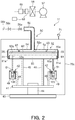
- FIG. 2 is a schematic sectional view illustrating the sterilizing device 11.
- the sterilizing device 11 includes a transport mechanism 40, and a supply unit 50 that supplies a sterilizing agent to the bottle 100 that is being transported by the transport mechanism 40.
- the transport mechanism 40 includes a wheel 41 that is rotatable, and a gripper 42 that is coupled to the wheel 41 and that transports the bottle 100 while holding the bottle 100.
- the wheel 41 is configured to rotate by using driving force from a predetermined driving source, and is horizontally attached to a swiveling shaft 44 that stands on a base 43.
- Supporting poles 45 extend upward from a round surface of the wheel 41, and a rotary plate 53 (described below) of the supply unit 50 is coupled to the upper ends of the supporting poles 45.
- Other supporting poles 48 extend upward from the round surface of the wheel 41, and grippers 42 for holding the bottles 100 are attached to upper parts of the supporting poles 48.
- Multiple supporting poles 48 and multiple grippers 42 are arranged at a predetermined pitch around the wheel 41.
- the multiple grippers 42 are coupled to the wheel 41 via the supporting poles 48 and rotate together with the wheel 41.
- a tunnel 49 is provided around the wheel 41 so as to surround the path of the bottles 100 held by the grippers 42.
- a sterilizing agent sprayed from a nozzle 51 (described below) is accumulated in the tunnel 49, and, as the bottle 100 passes through the tunnel 49, the outer surface of the bottle 100 is uniformly sterilized. It is possible to efficiently sterilize the outer surface of the bottle 100 by providing the tunnel 49.
- the tunnel 49 may be omitted.
- the supply unit 50 supplies the sterilizing agent to at least the inner surface of the bottle 100.
- the supply unit 50 may supply the sterilizing agent to the inner and outer surfaces of the bottle 100.
- the supply unit 50 includes the nozzle 51 for spraying the sterilizing agent, a fixed cover 52 including an inlet 52a through which the sterilizing agent flows into the fixed cover 52, and the rotary plate 53 that holds the nozzle 51 and that is rotatably provided in the fixed cover 52.
- the nozzle 51 does not move in the vertical direction and, without being inserted into the bottle 100, moves in synchronization with the bottle 100 that is being transported by the gripper 42 of the transport mechanism 40.
- the nozzle 51 is held by the rotary plate 53 so that an opening at the tip thereof directly faces the mouth of the bottle 100 held by the gripper 42.
- the nozzle 51 swivels around the swiveling shaft 44 together with the bottle 100 held by the gripper 42, and sprays the sterilizing agent to the bottle 100 while moving in synchronization with the bottle 100 that is being transported by the gripper 42 of the transport mechanism 40.
- the inside diameter of the opening at the tip of the nozzle 51 may be 2 mm or larger and 10 mm or smaller, and preferably may be 3 mm or larger and 8 mm or smaller.
- the inside diameter of the opening at the tip of the nozzle 51 is 2 mm or larger, it is possible to make the sterilizing agent, which is sprayed from the nozzle 51, efficiently adhere not only to the inner surface of the bottle 100 but also to the outer surface of the bottle 100. Therefore, it is possible to sterilize not only the inner surface of the bottle 100 but also the outer surface of the bottle 100.
- the inside diameter of the opening at the tip of the nozzle 51 is 10 mm or smaller, it is possible to efficiently spray the sterilizing agent to the inner surface of the bottle 100, and it is possible to sterilize the bottle 100 while heating the bottle 100 to a desirable temperature as described below.
- the tip of the nozzle 51 may have a truncated-cone shape.
- the nozzle 51 includes a flange 51a that is coaxial with the nozzle 51, and an annular wall 51b that protrudes from the periphery of the flange 51a toward the bottle 100.
- a nozzle having such a truncated-cone shape can guide a part of hot air that is supplied into the bottle 100 and that is blown out from the mouth to the outside of the bottle 100, toward the outer periphery of the mouth of the bottle 100.
- the mouth can be preheated and sterilized. Therefore, it is possible to efficiently and reliably sterilize a boundary portion between the outer surface and the inner surface of the bottle 100.
- the length of the nozzle 51 is 5 mm or larger and 200 mm or smaller.
- the length of the nozzle 51 is 5 mm or larger, it is possible to appropriately maintain a driving force of sterilizing-agent gas.
- the length of the nozzle 51 is 200 mm or smaller, it is possible to suppress condensation of gasified sterilizing agent due to decrease of temperature, and it is possible to effectively maintain a gas concentration that is necessary for bottle sterilization.
- the fixed cover 52 includes a top portion 54 having a substantially disc-like shape, and a side wall 55 that extends downward from the periphery of the top portion 54.
- the inlet 52a (described above) is formed in an upper central part of the top portion 54 of the fixed cover 52, and a conduit 56 is coupled to the inlet 52a.
- a valve 56a that controls flow of hydrogen peroxide gas in the conduit 56 is attached to the conduit 56.
- a gas supply device which is composed of a blower 57, a high efficiency particulate air (HEPA) filter 58, and an electric heater 59, are provided.
- a hydrogen-peroxide adding device 60 is installed on one or both of the upstream side and the downstream side of the electric heater 59. In a case where the hydrogen-peroxide adding device 60 is set on the downstream side of the electric heater 59, preferably, the hydrogen-peroxide adding device 60 mixes hydrogen peroxide in a gas phase into the pipe. If hydrogen peroxide is not in a gas phase, the residual value of hydrogen peroxide tends to increase.
- the hydrogen-peroxide adding device 60 may, for example, spray hydrogen peroxide in a liquid phase into the pipe.
- the temperature of the electric heater 59 is set to be the boiling point, or higher, of the sterilizing agent to be supplied but the temperature may be set to be 100°C or higher (preferably, 130°C or higher) in accordance with the degree to which the bottle 100 is to be sterilized.
- Another electric heater may be provided on the upstream side of the hydrogen-peroxide adding device 60, and the hydrogen-peroxide adding device 60 may spray hydrogen peroxide in a liquid phase to aseptic hot air (80°C or higher).
- the hydrogen-peroxide adding device 60 may be installed on both of the upstream side and the downstream side of the electric heater 59.
- the material of the bottle 100 is polyethylene terephthalate (PET)
- PET polyethylene terephthalate
- HDPE high-density polyethylene
- the adsorption amount of hydrogen peroxide is in the range of 1/5 to 1/20 and very small. Therefore, if the material of the bottle 100 is high-density polyethylene (HDPE), not only a method in which hydrogen peroxide solution is gasified and added to aseptic air but also a method in which hydrogen peroxide solution is sprayed to be mixed may be used.
- the hydrogen peroxide gas is supplied into the fixed cover 52 through the conduit 56, is blown out from the nozzle 51 to the bottle 100 via the rotary plate 53, and sterilizes the bottle 100.
- a pressure gauge 71 that measures the pressure of the inside of the sterilizing-agent spraying chamber 70c is attached to the sterilizing-agent spraying chamber 70c.
- the sterilizing agent may be any sterilizing agent that includes hydrogen peroxide of a concentration of 1% or higher. A 35% hydrogen peroxide solution diluted with ethanol may be used. When hydrogen peroxide is used as a sterilizing agent, a stabilizer included in the hydrogen peroxide component accumulates in the conduit 56.
- a structure that can cause water, an alkaline solution, an acid solution, or the like to flow to the supply unit 50 to perform cleaning in place (CIP) of the supply unit 50 is provided.
- a conduit 56b for CIP and a valve 56c that controls flow of a cleaning liquid in the conduit 56b is attached to the upstream side of the valve 56a.
- the conduit 56b for CIP may be attached to one or both of the upstream side and the downstream side of the hydrogen-peroxide adding device 60.
- the conduit 56b for CIP may be directly attached to the hydrogen-peroxide adding device 60.
- the sterilizing agent may be any substance that can deactivate microorganisms.
- Examples of the sterilizing agent include hydrogen peroxide, ethanol, peracetic acid, acetic acid, pernitric acid, nitric acid, sodium hypochlorite, chlorine, and sodium hydroxide. One of these may be used, or a combination of two or more of these may be used.
- the rotary plate 53 is coupled to the upper end of the supporting poles 45, and is rotatable together with the wheel 41 around the swiveling shaft 44.
- the rotary plate 53 has a substantially disc-like shape, and the rotary plate 53 has an opening 53a for supplying the sterilizing agent, which is supplied into the fixed cover 52, to the nozzle 51.
- a sealing member 61 is interposed between the fixed cover 52 and the rotary plate 53.
- the sealing member 61 is interposed between the side wall 55 of the fixed cover 52 and the rotary plate 53.
- the sealing member 61 prevents leakage of the sterilizing agent from the gap between the fixed cover 52 and the rotary plate 53.
- the sealing member 61 for example, polyetheretherketone (PEEK) or Teflon (registered trademark) may be used.
- the sealing member 61 may be interposed between the top portion 54 of the fixed cover 52 and the rotary plate 53.
- a cover 61a for preventing entry of foreign substances may be attached to the rotary plate 53.
- the cover 61a may be attached to an upper part of the tunnel 49.
- the sealing member 61 is interposed between the fixed cover 52 and the rotary plate 53.
- the position of the sealing member 61 is not limited to this.
- the sealing member 61 need not be interposed between the fixed cover 52 and the rotary plate 53.
- the diameter of the tip of the nozzle 51 attached to the rotary plate 53 is smaller than or equal to a half of the diameter of the mouth of the bottle 100, and is preferably 3 mm or larger.
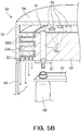
- the fixed cover 52 may include protruding portions 550 that protrude from the side wall 55 inward in the radial direction
- the rotary plate 53 may include protruding portions 530 that protrude outward in the radial direction.
- the sterilizing-agent flow path between the fixed cover 52 and the rotary plate 53 can be made to have a labyrinthine shape.
- the total area of a clearance A1 (dotted region in Fig. 5B ) between the fixed cover 52 (non-rotational body) and the rotary plate 53 (rotational body) in a plan view may be smaller than or equal to a half of the total area of entrances A2 (dotted regions in Fig. 5B ) of the openings 53a in a plan view, and preferably may be 1/5 of the total area of the entrances A2.
- one of the protruding portions 550 and 530 that is positioned nearest to the bottle 100 may have a through hole extending therethrough in the vertical direction.
- one of the protruding portion 530 that is positioned nearest to the bottle 100 has through-holes 531 extending therethrough in the vertical direction.
- a fixed shield plate 62 is interposed between the fixed cover 52 and the rotary plate 53.
- the fixed shield plate 62 is attached to the top portion 54 of the fixed cover 52 via an attachment member 63.
- the fixed shield plate 62 may be attached to the side wall 55 of the fixed cover 52.
- the fixed shield plate 62 has an opening 62a that is formed along the transport path of the bottle 100.
- the opening 62a has an arc shape in a plan view.
- the gripper 42 of the sterilizing device 11 receives the bottle 100 from the adjustment transport unit 5 on the upstream side thereof and transfers the bottle 100 to the air rinse device 14 on the downstream side thereof. Therefore, as illustrated in Fig. 6 , in a plan view, there is a region where the bottle 100 passes below the rotary plate 53 and a region where the bottle 100 does not pass below the rotary plate 53 (region where the wheel 41 is shown by a broken line).
- the fixed shield plate 62 has the openings 62a that are formed along the transport path of the bottle 100, it is possible to effectively supply the sterilizing agent that has flowed from the inlet 52a of the fixed cover 52 to, among the openings 53a of the rotary plate 53, each opening 53a that is positioned in the region where the bottle 100 passes below the rotary plate 53.
- the sterilizing agent it is possible to effectively supply the sterilizing agent to, among the nozzles 51, each nozzle 51 that directly faces the bottle 100. Therefore, it is possible to efficiently spray the sterilizing agent to the bottle 100, and to reduce the amount of the sterilizing agent used.
- the fixed shield plate 62 may be omitted.
- a chamber wall is provided between the wheel 41 and wheels that are disposed on both sides of the wheel 41 (in the example illustrate in Fig. 1 , a wheel of the adjustment transport unit 5 and a wheel of the air rinse device 14, which are disposed on both sides of the sterilizing device 11), or the entire periphery of the wheel 41 has a tunnel structure.
- the chamber wall or the tunnel structure can form a space having a small volume, and the sterilizing agent can be accumulated with high concentration in the space. Therefore, it is possible to enable the sterilizing agent accumulated in the space to effectively sterilize the outer surface of the bottle 100.
- the preform supply device 1 successively supplies a plurality of preforms 100a via the preform supply conveyor 2 to the receiving portion 34 of the preform transport unit 31 (preform supplying step S1 in Fig. 8 ).
- the preform sterilizing device 34a sterilizes each preform 100a by blowing mist or gas of hydrogen peroxide to the preform 100a and dries the preform 100a with hot air.
- the preform 100a is supplied to the heating portion 35 and heated by the heater 35a to a temperature of, for example, about 90°C or higher and 130°C or lower.
- the preform 100a which has been heated by the heating portion 35, is supplied to the transfer portion 36.
- the preform 100a is supplied from the transfer portion 36 to the blow molding unit 32.
- the bottle 100 is blow-molded by blow-molding the preform 100a, which has been supplied to the blow molding unit 32, by using a die (not shown) (bottle molding step S2 in Fig. 8 ). Then, the blow-molded bottle 100 is supplied to the bottle transport unit 33.
- the sterilizing device 11 sterilizes the bottle 100 by using hydrogen peroxide aqueous solution as a sterilizing agent (container sterilizing step S3 in Fig. 8 ).
- the hydrogen peroxide aqueous solution is gas or mist into which the solution is temporarily gasified at a temperature of the boiling point or higher, and is supplied toward the bottle 100.
- the mist of hydrogen peroxide aqueous solution adheres to the inner surface and the outer surface of the bottle 100, and sterilizes the inner and outer surfaces of the bottle 100.
- the transport mechanism 40 transports the bottle 100 (transport step S31 in Fig. 8 ).
- the gripper 42 which is coupled to the wheel 41, transports the bottle 100.
- the supply unit 50 which has the nozzle 51 for spraying the sterilizing agent, supplies the sterilizing agent to the bottle 100 that is being transported by the transport mechanism 40 (sterilizing-agent supplying step S32 in Fig. 8 ).
- the sterilizing agent flows through the conduit 56, and flows into the fixed cover 52 from the inlet 52a of the fixed cover 52.
- the sealing member 61 (an oil seal or a V-ring) is interposed between the fixed cover 52 and the rotary plate 53.
- the sealing member 61 can prevent leakage of the sterilizing agent through the gap between the fixed cover 52 (non-rotational body) and the rotary plate 53 (rotational body).
- the sealing member 61 is interposed between the fixed cover 52 and the rotary plate 53, it is possible to easily connect the non-rotational body and the rotational body without providing a so-called rotary joint in the supply unit 50 that supplies the sterilizing agent. Therefore, it is possible to reduce the manufacturing cost of the sterilizing device 11.
- the sterilizing agent which has flowed into the fixed cover 52, passes through the opening 62a of the fixed shield plate 62, and is supplied to the nozzle 51 from the opening 53a of the rotary plate 53.
- the opening 62a of the fixed shield plate 62 is formed along the transport path of the bottle 100 as described above.
- the sterilizing agent is effectively supplied to, among the openings 53a of the rotary plate 53, each opening 53a that is positioned in a region below which the bottle 100 passes. Therefore, it is possible to effectively supply the sterilizing agent to, among the nozzles 51, each nozzle 51 that directly faces the bottle 100.
- the sterilizing agent which has been supplied to the nozzle 51, is supplied to the bottle 100.
- the nozzle 51 does not move in the vertical direction and, without being inserted into the bottle 100, supplies the sterilizing agent to the bottle 100 while moving in synchronization with the bottle 100 that is being transported by the gripper 42 of the transport mechanism 40.
- the nozzle 51 does not move in the vertical direction and is not inserted into the bottle 100, it is possible to reduce the operation time for supplying the sterilizing agent. Because the nozzle 51 is not inserted into the bottle 100, even if the bottle 100 has a thin wall, it is possible to suppress deformation of the bottle 100 due to heat of the sterilizing agent.
- the nozzle 51 can supply the sterilizing agent to the bottle 100 while following the bottle 100.
- the sterilizing agent is efficiently supplied to the inner surface of the bottle 100, it is possible to heat the bottle 100 to a desirable temperature by using heat of the sterilizing agent. Therefore, it is possible to improve efficiency in sterilization of the bottle 100 without providing temperature adjusting equipment, which may be generally provided on the downstream side of the blow molding unit 32 in order to prevent thermal contraction of the bottle 100 and to improve sterilization efficiency.
- the concentration of the hydrogen peroxide gas may be, for example, 5 mg/L or larger and 50 mg/L or smaller.
- the concentration of the hydrogen peroxide gas is 5 mg/L or higher, it is possible to obtain a sufficient sterilizing effect.
- the concentration of the hydrogen peroxide gas is 50 mg/L or lower, it is possible to suppress increase of time for supplying hot air for removing residual hydrogen peroxide, and thus it is possible to reduce the sizes of the sterilizing device 11 and the content filling system 10.
- the amount of the mist of hydrogen peroxide is, on a 35 mass% basis, for example, 5 ⁇ L/bottle or larger and 100 ⁇ L/bottle or smaller.
- the amount of mist of hydrogen peroxide is 5 ⁇ L/bottle or higher, it is possible to obtain a sufficient sterilizing effect.
- the amount of the mist of hydrogen peroxide is 100 ⁇ L/bottle or smaller, it is possible to suppress increase of time for supplying hot air for removing residual hydrogen peroxide, and thus it is possible to reduce the sizes of the sterilizing device 11 and the content filling system 10.
- the flow rate of the sterilizing agent may be 30 L/min or higher and 400 L/min or lower, and preferably may be 50 L/min or lower and 300 L/min or lower.
- the flow rate of sterilizing agent is 30 L/min or higher, it is possible to increase the efficiency in sterilization of the bottle 100.
- the flow rate of sterilizing agent is 400 L/min or lower, it is possible to reduce the cost while maintaining the efficiency in sterilization of the bottle 100.
- the temperature of the sterilizing agent may be 70°C or higher and 200°C or lower.
- the temperature of the sterilizing agent is 70°C or higher, it is possible to improve the efficiency in sterilization of the bottle 100.
- the temperature of the sterilizing agent is 200°C or lower, even if the bottle 100 has a thin wall, it is possible to suppress deformation of the bottle 100 due to heat of the sterilizing agent.
- the time for supplying the sterilizing agent may be 0.2 seconds or longer and 4.0 seconds or shorter, and preferably may be 0.5 seconds or longer and 4.0 seconds or shorter.
- the time for supplying the sterilizing agent is 0.2 seconds or longer, it is possible to improve the efficiency in sterilization of the bottle 100.
- the time for supplying the sterilizing agent is 0.5 seconds or longer, it is possible to effectively warm the bottle 100 by using heat of the sterilizing agent.
- the time for supplying the sterilizing agent is 4.0 seconds or shorter, it is possible to reduce the operation time for supplying the sterilizing agent while maintaining the efficiency in sterilization of the bottle 100.
- the bottle 100 is supplied to the air rinse device 14, and the air rinse device 14 removes foreign substances, hydrogen peroxide, and the like from the bottle 100 while activating hydrogen peroxide by supplying aseptic heated air or room-temperature air.
- hydrogen peroxide may be gasified by mixing condensation mist of low-concentration hydrogen peroxide with room-temperature aseptic air, and the hydrogen peroxide gas may be supplied to the bottle 100.
- the bottle 100 is transported to the aseptic-water rinse device 15.
- the aseptic-water rinse device 15 performs cleaning by using aseptic water having a temperature of about 15°C or higher and 85°C or lower (rinse step S4 in Fig. 8 ).
- aseptic water having a temperature of about 15°C or higher and 85°C or lower is supplied to the bottle 100 at a flow rate of 5 L/min or higher and 15 L/min or lower.
- the bottle 100 is in an inverted state, the aseptic water is supplied into the bottle 100 from the mouth facing downward, and the aseptic water flows out of the bottle 100 from the mouth.
- the warm water washes off hydrogen peroxide adhering to the bottle 100 and removes foreign substances.
- the filling device 20 fills the bottle 100 with a content from the mouth of the bottle 100 while the bottle 100 is rotated (revolved) (filling step S5 in Fig. 8 ).
- the content is prepared and heat-sterilized in advance before the filling device 20 fills the bottle 100 with the content.
- the heating temperature is about 60°C or higher and 120°C or lower if the pH of the content is lower than 4.0, and about 115°C or higher and 150°C or lower if the pH of the content is 4.0 or higher.
- all microorganisms that is in the content before filling the bottle with and may grow in the product bottle 101 are all killed.
- the content that has been heat-sterilized is cooled to a temperature of about 3°C or higher and 40°C or lower.
- the filling device 20 fills the sterilized bottle 100 with the content that has been sterilized and cooled to room temperature.
- the temperature of the content during filling is, for example, about 3°C or higher and 40°C or lower.
- the transport wheel 12 transports the bottle 100, which has been filled with the content, to the cap attachment device 16.
- the cap sterilizing device 18 sterilizes the cap 80 beforehand (cap sterilizing step S6 in Fig. 8 ). First, the cap 80 is transported from the outside of the content filling system 10 into the cap sterilizing device 18. Next, the cap sterilizing device 18 sterilizes the inner and outer surfaces of the cap 80 by blowing mist or gas of hydrogen peroxide to the cap 80, and dries the cap 80 with hot air. Then, the cap 80 is supplied to the cap attachment device 16.
- the cap attachment device 16 attaches the sterilized cap 80 to the mouth of the bottle 100, which has been transported from the filling device 20, to close the bottle 100, thereby obtaining the product bottle 101 (closing step S7 in Fig. 8 ).
- the product bottle 101 is transported from the cap attachment device 16 to the product-bottle discharge section 22, and is discharged to the outside of the content filling system 10.
- Each of the steps from the container sterilizing step to the closing step is performed in an aseptic atmosphere surrounded by the sterilizing-agent spraying chamber 70c, the first sterilizing-agent removing chamber 70d, the second sterilizing-agent removing chamber 70e, or the aseptic chamber 70f, that is, in an aseptic environment.
- the inside of the sterilizing-agent spraying chamber 70c, the first sterilizing-agent removing chamber 70d, the second sterilizing-agent removing chamber 70e, or the aseptic chamber 70f is sterilized beforehand by spraying of hydrogen peroxide, ejection of warm water, or the like.
- aseptic air having a positive pressure is supplied into the sterilizing-agent spraying chamber 70c, the first sterilizing-agent removing chamber 70d, the second sterilizing-agent removing chamber 70e, or the aseptic chamber 70f so that the aseptic air is constantly blown out toward the outside from the sterilizing-agent spraying chamber 70c, the first sterilizing-agent removing chamber 70d, the second sterilizing-agent removing chamber 70e, or the aseptic chamber 70f.
- the content filling system 10 produces the bottle 100 with a production (transport) speed of 100 bpm or higher and 1500 bpm or lower.
- bpm bottle per minute refers to the transport speed of the bottles 100 per minute.
- the supply unit 50 includes the nozzle 51 for spraying a sterilizing agent; and the nozzle 51 does not move in the vertical direction and, without being inserted into the bottle 100, moves in synchronization with the bottle 100 that is being transported by the transport mechanism 40.
- the nozzle 51 does not move in the vertical direction and is not inserted into the bottle 100, it is possible to reduce an operation time for supplying the sterilizing agent.
- the nozzle 51 is not inserted into the bottle 100, it is possible to suppress deformation of the bottle 100 due to heat of the sterilizing agent, even if the bottle 100 has a thin wall.
- a mechanism for moving the nozzle 51 in the vertical direction is not necessary in the sterilizing device 11, and the cost of the sterilizing device 11 can be reduced.
- the existing technology described above has an advantage in that a bottle having a thick wall can be efficiently warmed by inserting the nozzle into the bottle.
- the thickness of the wall of the bottle 100 has been reduced in recent years, it has been found that it is possible to effectively warm the bottle 100 by making the time for supplying the sterilizing agent be 0.5 seconds or longer, even if the nozzle 51 is not inserted into the bottle 100.
- the mouth having a thick wall is warmed and the sterilization effect is improved by spraying high-temperature hydrogen peroxide gas to the mouth of the bottle 100 from above the mouth without inserting the nozzle 51 into the bottle 100. Therefore, with the present embodiment, it is possible to improve the effect of sterilizing the mouth, because the nozzle 51 does not move in the vertical direction and, without being inserted into the bottle 100, moves in synchronization with the bottle 100 that is being transported by the gripper 42 of the transport mechanism 40.
- the nozzle 51 can supply the sterilizing agent to the bottle 100 while following the bottle 100.
- the sterilizing agent is efficiently supplied to the inner surface of the bottle 100, it is possible to heat the bottle 100 to a desirable temperature by using heat of the sterilizing agent. Therefore, it is possible to increase the efficiency in sterilization of the bottle 100 without providing temperature adjusting equipment on the downstream side of the blow molding unit 32.
- the temperature adjusting equipment is not necessary, it is possible to reduce the size and the cost of the content filling system 10, and it becomes possible to install the content filling system 10 in a space in which it has not been possible to install the content filling system 10. Moreover, because the temperature adjusting equipment is not necessary, temperature monitoring equipment for monitoring the temperature of the bottle 100 is not necessary, and it is possible to further reduce the cost of the sterilizing device 11.
- the supply unit 50 includes the fixed cover 52 including the inlet 52a through which the sterilizing agent flows into the fixed cover 52, and the rotary plate 53 that holds the nozzle 51 and that is rotatably provided in the fixed cover 52; and the sealing member 61 is interposed between the fixed cover 52 and the rotary plate 53.
- the fixed cover 52 including the inlet 52a through which the sterilizing agent flows into the fixed cover 52
- the rotary plate 53 that holds the nozzle 51 and that is rotatably provided in the fixed cover 52
- the sealing member 61 is interposed between the fixed cover 52 and the rotary plate 53.
- the fixed shield plate 62 that has the opening 62a formed along the transport path of the bottle 100 is interposed between the fixed cover 52 and the rotary plate 53.
- the sterilizing agent it is possible to effectively supply the sterilizing agent to, among the openings 53a of the rotary plate 53, each opening 53a that is positioned in the region below which the bottle 100 passes. Therefore, it is possible to effectively supply the sterilizing agent to, among the nozzles 51, each nozzle 51 that directly faces the bottle 100.
- the container sterilizing device is not limited to this.
- the container sterilizing device may be a sterilizing device that performs peracetic acid sterilization that sterilizes the inner and outer surfaces of a bottle with peracetic acid solution (or gas or mist of peracetic acid, or a combination of these) and then rinses the inner and outer surfaces with aseptic water.
- the container sterilizing device may be: a sterilizing device that uses, instead of hydrogen peroxide or ethanol, one of peracetic acid, acetic acid, pernitric acid, nitric acid, sodium hypochlorite, chlorine, sodium hydroxide, and the like as a sterilizing agent; a sterilizing device that uses only one of these as a sterilizing agent; or a sterilizing device that uses a combination of two or more of these as a sterilization agent.
- the sterilizing device may be used not only to sterilize a bottle but also to sterilize a preform, a cup, a pouch, a paper container, or a combination body of any of these.
- the transport mechanism 40 includes the wheel 41 that is rotatable and the gripper 42 that is coupled to the wheel 41 and that transports the bottle 100 while holding the bottle 100 has been described.
- the transport mechanism 40 is not limited to this.
- a star wheel or a conveyor may be used as the transport mechanism 40.
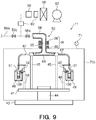
- the sterilizing device 11 may include a rotary joint R that connects a non-rotational body and a rotational body.
- a manifold 64 into which a sterilizing agent flows, is fixed to the upper end of the supporting poles 45.
- a conduit 65 extends upward from an upper central part of the manifold 64 along an extension line of the axis of the swiveling shaft 44.
- the conduit 65 is held by a frame member of the sterilizing-agent spraying chamber 70c, which is coupled to the base 43, via a bearing 66 that configures a part of the rotary joint R.
- the manifold 64 is rotatable together with the wheel 41 around the swiveling shaft 44.
- Supply pipes 67 for supplying the sterilizing agent respectively extend from peripheral parts of the manifold 64 toward the grippers 42, and the nozzle 51 is attached to the tip of each of the supply pipes 67.
- the nozzle 51 is fixed to the supporting pole 48.
- the conduit 56 is connected to an upper end of the conduit 65, which extends upward from the manifold 64, via a seal portion 68 that configures a part of the rotary joint R.
- the conduit 65 rotates together with the manifold 64 relative to the conduit 56, and the seal portion 68 prevents leakage of the sterilizing agent from a connection portion where the conduits 56 and 65 are connected. Also in this case, it is possible to obtain the advantageous effects described above.
- the rotary plate 53 is not limited to this.
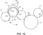
- an auxiliary member 90 for supplying the sterilizing agent may be attached to the rotary plate 53.
- the auxiliary member 90 includes a body 91 which is hollow and an introducing portion 92 for introducing the sterilizing agent into the body 91.
- the body 91 covers, among openings 53c (described below) of the rotary plate 53, each opening 53c that is positioned in a region below which the bottle 100 passes.
- a protective member 93 for protecting the body 91 and the rotary plate 53 and improving closeness of contact with the rotary plate 53, is attached to an end of the body 91 on a side opposite to the introducing portion 92.
- a resin material such as a fluorine resin or polyetheretherketone (PEEK) may be used.
- the plurality of openings 53c that are arranged at intervals in the circumferential direction are formed in a side surface 53b of the rotary plate 53.
- the pitch of the plurality of the openings 53c is the substantially the same as the pitch the nozzle 51 so that each of the openings 53c and a corresponding one of the openings at the tip of the nozzle 51 communicate with each other as illustrated in Fig. 11 .
- the body 91 of the auxiliary member 90 covers, among the openings 53c of the rotary plate 53, each opening 53c that is positioned in the region below which the bottle 100 passes, it is possible to effectively supply the sterilizing agent to, among the openings 53c of the rotary plate 53, each opening 53c that is positioned in the region below which the bottle 100 passes. Therefore, it is possible to effectively supply the sterilizing agent to, among the nozzles 51, each nozzle 51 that directly faces the bottle 100. Therefore, it is possible to efficiently spray the sterilizing agent to the bottle 100, and to reduce the amount of the sterilizing agent used.
- the content filling system 10 includes the bottle molding section 30 .
- the content filling system 10 is not limited to this.
- the content filling system may be configured to successively receive a molded empty bottle 100 from the outside and to transport the received bottle 100 toward the sterilizing device 11.
- the advantageous effects described above if the content filling system 10 successively receives a molded empty bottle 100 from the outside, there may be a case where the bottle 100 to be sterilized by the sterilizing device 11 has released heat generated by blow molding.
- the bottle 100 can be heated to a desirable temperature by using heat of the sterilizing agent, it is possible to improve the efficiency in sterilization of the bottle 100 without providing temperature adjusting equipment on the downstream side of the blow molding unit 32.
- a plurality of constituent elements disclosed in the embodiments and the modifications described above may be combined as appropriate if necessary. Some of the constituent elements shown in the embodiments and the modifications described above may be omitted.
Landscapes
- Manufacturing & Machinery (AREA)
- Mechanical Engineering (AREA)
- Engineering & Computer Science (AREA)
- Health & Medical Sciences (AREA)
- Chemical & Material Sciences (AREA)
- General Chemical & Material Sciences (AREA)
- Chemical Kinetics & Catalysis (AREA)
- Epidemiology (AREA)
- Life Sciences & Earth Sciences (AREA)
- Animal Behavior & Ethology (AREA)
- General Health & Medical Sciences (AREA)
- Public Health (AREA)
- Veterinary Medicine (AREA)
- Filling Of Jars Or Cans And Processes For Cleaning And Sealing Jars (AREA)
- Apparatus For Disinfection Or Sterilisation (AREA)
Abstract
Description
- The present disclosure relates to a container sterilizing device, a content filling system, a container sterilizing method, and a content filling method.
- An aseptic filling system that fills a sterilized container (plastic bottle) with a sterilized content in an aseptic environment and then closes the container with a cap is known. To be specific, in the aseptic filling system, a molded container is supplied to the aseptic filling system, and hydrogen peroxide aqueous solution as a sterilizing agent is sprayed to the container in the aseptic filling system. Subsequently, the container is dried to be sterilized, and then the container is aseptically filled with a content.
- As a method of sterilizing a container, a sterilizing method in which a sterilizing agent is sprayed from the mouth of the container while inserting a nozzle into the container, and a sterilizing method in which a sterilizing agent is supplied to the inner surface and the outer surface of the container without inserting a nozzle into the container are known (see, for
example Patent Literatures 1 and 2). - However, as described in
Patent Literature 1, in the sterilizing method that sterilizes a container while inserting a nozzle into a container, it is necessary to move the nozzle up and down in order to insert the nozzle into the container. Therefore, the sterilizing method has a problem in that it takes a long operation time to perform a step of supplying the sterilizing agent and the cost of a sterilizing device is high. In recent years, reduction in weight of a container has been demanded, and the thickness of the wall of the container has decreased. Therefore, when a sterilizing agent is sprayed to a container having a thin wall while inserting a nozzle into the container, the container may deform due to heat of the sterilizing agent. - As described in
Patent Literature 2, with the sterilizing method in which the sterilizing agent is supplied to the inner surface and the outer surface of the container without inserting a nozzle into the container, there is a case where it is difficult to efficiently supply the sterilizing agent to the inner surface of the container. In this case, a problem arises in that it is necessary to increase the amount of the sterilizing agent used, in order to efficiently supply the sterilizing agent to the inner surface of the container. - As described in Patent Literature 3, there is a method in which heat applied to a bottle due to blow molding is used for sterilization. However, the cost of the method is high because it is necessary to provide temperature adjusting equipment for adjusting the temperature of the bottle, and it is necessary to measure the temperature of the bottle because heat after blow molding is one of the sterilizing factors.
-
- [Patent Literature 1]
Japanese Patent No. 4526820 - [Patent Literature 2]
Japanese Patent No. 4700946 - [Patent Literature 3]
Japanese Patent No. 5332603 - The present disclosure has been made in consideration of such points, and an object of the present disclosure is to provide a container sterilizing device, a content filling system, a container sterilizing method, and a content filling method with each of which it is possible to reduce the cost of a sterilizing device and to efficiently supply a sterilizing agent to a container.
- An embodiment of the present disclosure is a container sterilizing device including: a transport mechanism that transports a container; and a supply unit that supplies a sterilizing agent to the container that is being transported by the transport mechanism. The supply unit includes a nozzle for spraying the sterilizing agent. The nozzle does not move in a vertical direction and, without being inserted into the container, moves in synchronization with the container that is being transported by the transport mechanism.
- In an embodiment of the present disclosure, the supply unit may further include a fixed cover that includes an inlet through which the sterilizing agent flows into the fixed cover, and a rotary plate that holds the nozzle and that is rotatably provided in the fixed cover; and a sealing member may be interposed between the fixed cover and the rotary plate.
- In an embodiment of the present disclosure, a fixed shield plate that has an opening formed along a transport path of the container may be interposed between the fixed cover and the rotary plate.
- An embodiment of the present disclosure is a content filling system including: the container sterilizing device according to the present disclosure; a filling device that fills the container with a content; and a cap attachment device that closes the container with a cap.
- An embodiment of the present disclosure is a container sterilizing method including: a transport step of transporting a container by using a transport mechanism; and a sterilizing-agent supplying step of supplying a sterilizing agent to the container that is being transported by the transport mechanism by using a supply unit including a nozzle for spraying the sterilizing agent. In the sterilizing-agent supplying step, the nozzle does not move in a vertical direction and, without being inserted into the container, supplies the sterilizing agent to the container while moving in synchronization with the container that is being transported by the transport mechanism.
- In an embodiment of the present disclosure, the supply unit may include a fixed cover that includes an inlet through which the sterilizing agent flows into the fixed cover, and a rotary plate that holds the nozzle and that is rotatably provided in the fixed cover; and a sealing member may be interposed between the fixed cover and the rotary plate.
- In an embodiment of the present disclosure, a fixed shield plate that has an opening formed along a transport path of the container may be interposed between the fixed cover and the rotary plate.
- An embodiment of the present disclosure is a content filling method including: a step of sterilizing a container by using the container sterilizing method according to the present disclosure; a step of filling the container with a content; and a step of closing the container with a cap.
- With the present disclosure, it is possible to reduce the cost of a sterilizing device, and it is possible to efficiently supply a sterilizing agent to a container. Brief Description of Drawings
-
- [
Fig. 1] Fig. 1 is a schematic plan view illustrating a content filling system according to the present embodiment. - [
Fig. 2] Fig. 2 is a schematic sectional view illustrating a container sterilizing device according to the present embodiment. - [
Fig. 3] Fig. 3 is an enlarged schematic front view illustrating a nozzle of the container sterilizing device according to the present embodiment. - [
Fig. 4] Fig. 4 is a schematic sectional view illustrating another example of the container sterilizing device according to the present embodiment. - [
Fig. 5A] Fig. 5A is a schematic sectional view illustrating other examples of a fixed cover and a rotary plate of the container sterilizing device according to the present embodiment. - [
Fig. 5B] Fig. 5B is a schematic sectional view illustrating other examples of the fixed cover and the rotary plate of the container sterilizing device according to the present embodiment. - [
Fig. 6] Fig. 6 is an enlarged schematic plan view illustrating the container sterilizing device according to the present embodiment. - [
Fig. 7] Fig. 7 is a schematic perspective view illustrating a fixed shield plate of the container sterilizing device according to the present embodiment. - [
Fig. 8] Fig. 8 is a flowchart illustrating a content filling method using the content filling system according to the present embodiment. - [
Fig. 9] Fig. 9 is a schematic sectional view illustrating a modification of the container sterilizing device according to the present embodiment. - [
Fig. 10] Fig. 10 is an enlarged schematic plan view illustrating a modification of the container sterilizing device according to the present embodiment. - [
Fig. 11] Fig. 11 is a sectional view (sectional view taken along line XI-XI ofFig. 10 ) illustrating a rotary plate and an auxiliary member of the modification of the container sterilizing device according to the present embodiment. - Hereafter, embodiments of the present invention will be described with reference to the drawings.
Figs. 1 to 8 illustrate an embodiment of the present invention. - First, referring to
Fig. 1 , a content filling system (aseptic filling system) according to the embodiment will be described. -
Fig. 1 illustrates a content filling system 10 that fills a bottle 100 (container) with a content such as a beverage. Thebottle 100 can be made by biaxial-stretch blow-molding a preform that has been made by injection-molding a synthetic resin material. Preferably, a thermoplastic resin, in particular, polyethylene (PE), polypropylene (PP), polyethylene terephthalate (PET), or polyethylene naphthalate (PEN) is used as the material of thebottle 100. In addition, the container may be a glass container, a can, a paper container, a pouch, or a combined container of any of these. In the present embodiment, a case where a bottle is used as the container will be described as an example. - As illustrated in
Fig. 1 , the content filling system 10 includes abottle molding section 30, a sterilizing device 11 (container sterilizing device), anair rinse device 14, an aseptic-water rinse device 15, a filling device 20 (filler), a cap attachment device 16 (a capper, a seamer, and a capping machine), and a product-bottle discharge section 22. Thebottle molding section 30, thesterilizing device 11, theair rinse device 14, the aseptic-water rinse device 15, thefilling device 20, thecap attachment device 16, and the product-bottle discharge section 22 are arranged in this order from the upstream side toward the downstream side in the transport direction of thebottle 100. A plurality oftransport wheels 12 that transport thebottle 100 between these devices are provided between an adjustment transport unit 5 (described below), the sterilizingdevice 11, theair rinse device 14, the aseptic-water rinse device 15, thefilling device 20, and thecap attachment device 16. - The
bottle molding section 30 successively receives a preform 100a from the outside, molds thebottle 100, and transports themolded bottle 100 toward the sterilizingdevice 11 to supply the moldedbottle 100. Thus, because thebottle molding section 30 is configured to receive thepreform 100a and to mold thebottle 100, the content filling system 10 can continuously perform a step of supplying thepreform 100a, a step of molding thebottle 100, a step of filling thebottle 100 with a content, and a step of closing thebottle 100. In this case, the transport cost can be reduced, because, instead of thebottle 100 having a large volume, the preform 100a having a small volume can be transported from the outside to the content filling system 10. - The
bottle molding section 30 includes apreform transport unit 31 that transports the preform 100a, ablow molding unit 32 that molds thebottle 100 by blow-molding thepreform 100a, and abottle transport unit 33 that transports the moldedbottle 100. - The
preform transport unit 31 includes a receiving portion 34 that receives thepreform 100a that is supplied from apreform supply device 1 via apreform supply conveyor 2, a heating portion 35 that receives thepreform 100a from the receiving portion 34 and heats the preform 100a while transporting thepreform 100a, and a transfer portion 36 that receives thepreform 100a that has been heated by the heating portion 35 and transfers the preform 100a to theblow molding unit 32. In the receiving portion 34, apreform sterilizing device 34a for sterilizing thepreform 100a is provided. Thepreform sterilizing device 34a blows mist or gas of hydrogen peroxide aqueous solution to the preform 100a to sterilize the preform 100a (preliminary sterilization). The sterilizing agent for sterilizing thepreform 100a may be any substance that can deactivate microorganisms. Examples of the sterilizing agent include hydrogen peroxide, peracetic acid, acetic acid, pernitric acid, nitric acid, a chlorine-based agent, sodium hydroxide, potassium hydroxide, alcohols such as ethyl alcohol and isopropyl alcohol, chlorine dioxide, ozone water, acid water, and a surface-active agent. One of these may be used, or a combination of two or more of these may be used. - The heating portion 35 includes a
heater 35a that heats thepreform 100a. Theheater 35a may be, for example, an infrared heater. Theheater 35a heats the preform 100a to a temperature of about 90°C or higher and 130°C or lower. The temperature of the mouth of the preform 100a is controlled to be 70°C or lower, in order to prevent deformation and the like. - The
blow molding unit 32 includes a die (not shown), and thebottle 100 is molded by blow-molding thepreform 100a by using the die. - Between the
bottle molding section 30 and the sterilizingdevice 11, theadjustment transport unit 5, which receives thebottle 100 from thebottle transport unit 33 of thebottle molding section 30 and transfers thebottle 100 to the sterilizingdevice 11, is provided. Theadjustment transport unit 5 is accommodated in an atmosphere shut-offchamber 70b (described below). Thus, because theadjustment transport unit 5 is accommodated in the atmosphere shut-offchamber 70b, it is possible to suppress a failure such that gas or mist of the sterilizing agent or a mixture of these that is generated in a sterilizing-agent spraying chamber 70c (described below) flows into amolding section chamber 70a (described below) that accommodates thebottle molding section 30. - The sterilizing
device 11 sterilizes the inside of thebottle 100 by ejecting the sterilizing agent to thebottle 100. Thus, thebottle 100 is sterilized by the sterilizing agent before thebottle 100 is filled with a content. As the sterilizing agent, for example, hydrogen peroxide aqueous solution is used. The sterilizingdevice 11 generates mist or gas of the hydrogen peroxide aqueous solution, and sprays the mist or gas to the inner and outer surfaces of thebottle 100. Because thebottle 100 is sterilized by the mist or gas of the hydrogen peroxide aqueous solution, the inner and outer surfaces of thebottle 100 are uniformly sterilized. - The air rinse
device 14 supplies heated aseptic air or room-temperature aseptic air to thebottle 100, thereby removing foreign substances, hydrogen peroxide, and the like from the inside of thebottle 100 while activating hydrogen peroxide. As necessary, room-temperature aseptic air may be mixed with condensation mist of low-concentration hydrogen peroxide to gasify hydrogen peroxide, and the mixture may be supplied to thebottle 100. The configuration of the air rinsedevice 14 may be substantially the same as that of the sterilizingdevice 11 illustrated inFig. 2 (described below). - The aseptic-water rinse
device 15 cleans thebottle 100, which has been sterilized by hydrogen peroxide as a sterilizing agent, by using aseptic water having a temperature in the range of 15°C to 85°C. Thus, hydrogen peroxide adhering to thebottle 100 is washed away, and foreign substances are removed. - The filling
device 20 fills the inside of thebottle 100 with a content, which has been sterilized, from the mouth of thebottle 100. The fillingdevice 20 fills thebottle 100 in an empty state with a content. The fillingdevice 20 fills a plurality ofbottles 100 with contents while thebottles 100 are rotated and transported. - The
cap attachment device 16 closes thebottle 100 by attaching acap 80 to the mouth of thebottle 100. Thecap attachment device 16 closes the mouth of thebottle 100 with thecap 80 and tightly seals the mouth so that external air and microorganism may not enter thebottle 100. Thecap attachment device 16 attaches thecap 80 to the mouth of each of a plurality of thebottles 100, which have been filled with contents, while thebottles 100 rotate (revolve). Thus, aproduct bottle 101 is obtained by attaching thecap 80 to the mouth of thebottle 100. - The
cap 80 is sterilized beforehand by acap sterilizing device 18. Thecap sterilizing device 18 is disposed, for example, at a position that is outside of anaseptic chamber 70f (described below) and near thecap attachment device 16. Thecap sterilizing device 18 gathersmultiple caps 80, which have been transported from the outside of the content filling system 10, and transports thecaps 80 toward thecap attachment device 16 in a row. While thecaps 80 are being transported toward thecap attachment device 16, mist or gas of hydrogen peroxide is blown toward the inner and outer surfaces of thecaps 80, and then thecaps 80 are dried with hot air to be sterilized. - The product-
bottle discharge section 22 continuously discharges theproduct bottle 101, to which thecap attachment device 16 has attached thecap 80, toward the outside of the content filling system 10. - The content filling system 10 includes the
molding section chamber 70a, the atmosphere shut-offchamber 70b, the sterilizing-agent spraying chamber 70c, a first sterilizing-agent removing chamber 70d, a second sterilizing-agent removing chamber 70e, and theaseptic chamber 70f. Thebottle molding section 30 is accommodated in themolding section chamber 70a, and theadjustment transport unit 5 is accommodated in the atmosphere shut-offchamber 70b. The sterilizingdevice 11 is accommodated in the sterilizing-agent spraying chamber 70c, the air rinsedevice 14 is accommodated in the first sterilizing-agent removing chamber 70d, and the aseptic-water rinsedevice 15 is accommodated in the second sterilizing-agent removing chamber 70e. The fillingdevice 20, thecap sterilizing device 18, and thecap attachment device 16 described above are accommodated in theaseptic chamber 70f. The content filling system 10 may be, for example, an aseptic filling system. In this case, the inside of each of the sterilizing-agent spraying chamber 70c, the first sterilizing-agent removing chamber 70d, the second sterilizing-agent removing chamber 70e, and theaseptic chamber 70f is maintained in an aseptic state. - Alternatively, the content filling system 10 may be a high-temperature filling system that fills a container with a content in a high temperature of 85°C or higher and lower than 100°C. The content filling system 10 may be an intermediate-temperature filling system that fills a container with a content in an intermediate temperature of 55°C or higher and lower than 85°C.
- Next, referring to
Fig. 2 , the sterilizing device 11 (container sterilizing device) according to the present embodiment will be described in detail.Fig. 2 is a schematic sectional view illustrating the sterilizingdevice 11. As illustrated inFig. 2 , the sterilizingdevice 11 includes a transport mechanism 40, and asupply unit 50 that supplies a sterilizing agent to thebottle 100 that is being transported by the transport mechanism 40. In the present embodiment, the transport mechanism 40 includes awheel 41 that is rotatable, and agripper 42 that is coupled to thewheel 41 and that transports thebottle 100 while holding thebottle 100. - The
wheel 41 is configured to rotate by using driving force from a predetermined driving source, and is horizontally attached to a swivelingshaft 44 that stands on abase 43. Supportingpoles 45 extend upward from a round surface of thewheel 41, and a rotary plate 53 (described below) of thesupply unit 50 is coupled to the upper ends of the supportingpoles 45. - Other supporting
poles 48 extend upward from the round surface of thewheel 41, andgrippers 42 for holding thebottles 100 are attached to upper parts of the supportingpoles 48. Multiple supportingpoles 48 andmultiple grippers 42 are arranged at a predetermined pitch around thewheel 41. Themultiple grippers 42 are coupled to thewheel 41 via the supportingpoles 48 and rotate together with thewheel 41. Atunnel 49 is provided around thewheel 41 so as to surround the path of thebottles 100 held by thegrippers 42. A sterilizing agent sprayed from a nozzle 51 (described below) is accumulated in thetunnel 49, and, as thebottle 100 passes through thetunnel 49, the outer surface of thebottle 100 is uniformly sterilized. It is possible to efficiently sterilize the outer surface of thebottle 100 by providing thetunnel 49. However, thetunnel 49 may be omitted. For example, it is possible to efficiently sterilize the outer surface of thebottle 100 by providing a camber wall between thewheel 41 and wheels that are disposed on both sides of the wheel 41 (in the example illustrated inFig. 1 , a wheel of theadjustment transport unit 5 and a wheel of the air rinsedevice 14, which are disposed on both sides of the sterilizing device 11) so that the camber wall forms a space having a small volume. - Next, the
supply unit 50 of the sterilizingdevice 11 will be described. Thesupply unit 50 supplies the sterilizing agent to at least the inner surface of thebottle 100. Thesupply unit 50 may supply the sterilizing agent to the inner and outer surfaces of thebottle 100. Thesupply unit 50 includes thenozzle 51 for spraying the sterilizing agent, a fixedcover 52 including aninlet 52a through which the sterilizing agent flows into the fixedcover 52, and therotary plate 53 that holds thenozzle 51 and that is rotatably provided in the fixedcover 52. Thenozzle 51 does not move in the vertical direction and, without being inserted into thebottle 100, moves in synchronization with thebottle 100 that is being transported by thegripper 42 of the transport mechanism 40. In this case, thenozzle 51 is held by therotary plate 53 so that an opening at the tip thereof directly faces the mouth of thebottle 100 held by thegripper 42. Thus, as thewheel 41 and therotary plate 53 rotate, thenozzle 51 swivels around the swivelingshaft 44 together with thebottle 100 held by thegripper 42, and sprays the sterilizing agent to thebottle 100 while moving in synchronization with thebottle 100 that is being transported by thegripper 42 of the transport mechanism 40. - The inside diameter of the opening at the tip of the
nozzle 51 may be 2 mm or larger and 10 mm or smaller, and preferably may be 3 mm or larger and 8 mm or smaller. When the inside diameter of the opening at the tip of thenozzle 51 is 2 mm or larger, it is possible to make the sterilizing agent, which is sprayed from thenozzle 51, efficiently adhere not only to the inner surface of thebottle 100 but also to the outer surface of thebottle 100. Therefore, it is possible to sterilize not only the inner surface of thebottle 100 but also the outer surface of thebottle 100. When the inside diameter of the opening at the tip of thenozzle 51 is 10 mm or smaller, it is possible to efficiently spray the sterilizing agent to the inner surface of thebottle 100, and it is possible to sterilize thebottle 100 while heating thebottle 100 to a desirable temperature as described below. The tip of thenozzle 51 may have a truncated-cone shape. In this case, as illustrated inFig. 3 , thenozzle 51 includes aflange 51a that is coaxial with thenozzle 51, and anannular wall 51b that protrudes from the periphery of theflange 51a toward thebottle 100. A nozzle having such a truncated-cone shape can guide a part of hot air that is supplied into thebottle 100 and that is blown out from the mouth to the outside of thebottle 100, toward the outer periphery of the mouth of thebottle 100. Thus, the mouth can be preheated and sterilized. Therefore, it is possible to efficiently and reliably sterilize a boundary portion between the outer surface and the inner surface of thebottle 100. In this case, preferably, the length of thenozzle 51 is 5 mm or larger and 200 mm or smaller. When the length of thenozzle 51 is 5 mm or larger, it is possible to appropriately maintain a driving force of sterilizing-agent gas. When the length of thenozzle 51 is 200 mm or smaller, it is possible to suppress condensation of gasified sterilizing agent due to decrease of temperature, and it is possible to effectively maintain a gas concentration that is necessary for bottle sterilization. - As illustrated in
Fig. 2 , the fixedcover 52 includes atop portion 54 having a substantially disc-like shape, and aside wall 55 that extends downward from the periphery of thetop portion 54. Theinlet 52a (described above) is formed in an upper central part of thetop portion 54 of the fixedcover 52, and aconduit 56 is coupled to theinlet 52a. Avalve 56a that controls flow of hydrogen peroxide gas in theconduit 56 is attached to theconduit 56. - On the upstream side of the
conduit 56, a gas supply device, which is composed of ablower 57, a high efficiency particulate air (HEPA)filter 58, and anelectric heater 59, are provided. A hydrogen-peroxide adding device 60 is installed on one or both of the upstream side and the downstream side of theelectric heater 59. In a case where the hydrogen-peroxide adding device 60 is set on the downstream side of theelectric heater 59, preferably, the hydrogen-peroxide adding device 60 mixes hydrogen peroxide in a gas phase into the pipe. If hydrogen peroxide is not in a gas phase, the residual value of hydrogen peroxide tends to increase. On the other hand, in a case where the hydrogen-peroxide adding device 60 is set on the upstream side of theelectric heater 59, the hydrogen-peroxide adding device 60 may, for example, spray hydrogen peroxide in a liquid phase into the pipe. In this case, preferably, the temperature of theelectric heater 59 is set to be the boiling point, or higher, of the sterilizing agent to be supplied but the temperature may be set to be 100°C or higher (preferably, 130°C or higher) in accordance with the degree to which thebottle 100 is to be sterilized. Another electric heater may be provided on the upstream side of the hydrogen-peroxide adding device 60, and the hydrogen-peroxide adding device 60 may spray hydrogen peroxide in a liquid phase to aseptic hot air (80°C or higher). The hydrogen-peroxide adding device 60 may be installed on both of the upstream side and the downstream side of theelectric heater 59. Here, if the material of thebottle 100 is polyethylene terephthalate (PET), hydrogen peroxide is easily adsorbed and the residual value tends increase; but, if the material is high-density polyethylene (HDPE), the adsorption amount of hydrogen peroxide is in the range of 1/5 to 1/20 and very small. Therefore, if the material of thebottle 100 is high-density polyethylene (HDPE), not only a method in which hydrogen peroxide solution is gasified and added to aseptic air but also a method in which hydrogen peroxide solution is sprayed to be mixed may be used. The hydrogen peroxide gas is supplied into the fixedcover 52 through theconduit 56, is blown out from thenozzle 51 to thebottle 100 via therotary plate 53, and sterilizes thebottle 100. Apressure gauge 71 that measures the pressure of the inside of the sterilizing-agent spraying chamber 70c is attached to the sterilizing-agent spraying chamber 70c. The sterilizing agent may be any sterilizing agent that includes hydrogen peroxide of a concentration of 1% or higher. A 35% hydrogen peroxide solution diluted with ethanol may be used. When hydrogen peroxide is used as a sterilizing agent, a stabilizer included in the hydrogen peroxide component accumulates in theconduit 56. Therefore, in order to prevent blocking of thenozzle 51 by the stabilizer accumulated in theconduit 56, preferably, a structure that can cause water, an alkaline solution, an acid solution, or the like to flow to thesupply unit 50 to perform cleaning in place (CIP) of thesupply unit 50 is provided. In the illustrated example, aconduit 56b for CIP and avalve 56c that controls flow of a cleaning liquid in theconduit 56b is attached to the upstream side of thevalve 56a. Theconduit 56b for CIP may be attached to one or both of the upstream side and the downstream side of the hydrogen-peroxide adding device 60. Alternatively, theconduit 56b for CIP may be directly attached to the hydrogen-peroxide adding device 60. - The sterilizing agent may be any substance that can deactivate microorganisms. Examples of the sterilizing agent include hydrogen peroxide, ethanol, peracetic acid, acetic acid, pernitric acid, nitric acid, sodium hypochlorite, chlorine, and sodium hydroxide. One of these may be used, or a combination of two or more of these may be used.
- As described above, the
rotary plate 53 is coupled to the upper end of the supportingpoles 45, and is rotatable together with thewheel 41 around the swivelingshaft 44.
Therotary plate 53 has a substantially disc-like shape, and therotary plate 53 has anopening 53a for supplying the sterilizing agent, which is supplied into the fixedcover 52, to thenozzle 51. - A sealing
member 61 is interposed between the fixedcover 52 and therotary plate 53. To be specific, the sealingmember 61 is interposed between theside wall 55 of the fixedcover 52 and therotary plate 53. The sealingmember 61 prevents leakage of the sterilizing agent from the gap between the fixedcover 52 and therotary plate 53. As the sealingmember 61, for example, polyetheretherketone (PEEK) or Teflon (registered trademark) may be used. The sealingmember 61 may be interposed between thetop portion 54 of the fixedcover 52 and therotary plate 53. If there is a possibility that the sealingmember 61 wears and deteriorates, in order to prevent the sealingmember 61 from entering thebottle 100, acover 61a for preventing entry of foreign substances may be attached to therotary plate 53. As illustrated inFig. 4 , thecover 61a may be attached to an upper part of thetunnel 49. In the illustrated example, the sealingmember 61 is interposed between the fixedcover 52 and therotary plate 53. However, the position of the sealingmember 61 is not limited to this. For example, as illustrated inFig. 5A , the sealingmember 61 need not be interposed between the fixedcover 52 and therotary plate 53. In this case, it is possible to supply sterilizing-agent gas to the outer surface of thebottle 100 through the gap between the fixed cover 52 (non-rotational body) and the rotary plate 53 (rotational body). That is, it is possible to guide the sterilizing-agent gas that has passed through the gap between the fixedcover 52 and therotary plate 53 to the outer surface of thebottle 100. Therefore, an additional nozzle for sterilizing the outer surface of thebottle 100 is not necessary. In this case, preferably, the diameter of the tip of thenozzle 51 attached to therotary plate 53 is smaller than or equal to a half of the diameter of the mouth of thebottle 100, and is preferably 3 mm or larger. Thus, it is possible to efficiently guide the sterilizing-agent gas that has passed through theopening 53a to the inner surface of thebottle 100. Moreover, for example, it is also possible to suppress leakage of the sterilizing agent through the gap between the fixedcover 52 and therotary plate 53 by using a labyrinthine structure. In this case, as illustrated inFig. 5B , the fixedcover 52 may include protrudingportions 550 that protrude from theside wall 55 inward in the radial direction, and therotary plate 53 may include protrudingportions 530 that protrude outward in the radial direction. Thus, the sterilizing-agent flow path between the fixedcover 52 and therotary plate 53 can be made to have a labyrinthine shape. In this case, the total area of a clearance A1 (dotted region inFig. 5B ) between the fixed cover 52 (non-rotational body) and the rotary plate 53 (rotational body) in a plan view may be smaller than or equal to a half of the total area of entrances A2 (dotted regions inFig. 5B ) of theopenings 53a in a plan view, and preferably may be 1/5 of the total area of the entrances A2. In this case, it is possible to suppress leakage of the sterilizing agent mist or gas and to effectively introduce the sterilizing agent into thebottle 100. Moreover, in this case, one of the protrudingportions bottle 100 may have a through hole extending therethrough in the vertical direction. In the illustrated example, one of the protrudingportion 530 that is positioned nearest to thebottle 100 has through-holes 531 extending therethrough in the vertical direction. Thus, it is possible to guide the sterilizing-agent gas that has passed through the gap between the fixedcover 52 and therotary plate 53 to the outer surface of thebottle 100. Therefore, an additional nozzle for sterilizing the outer surface of thebottle 100 is not necessary. - Moreover, as illustrated in
Fig. 2 , a fixedshield plate 62 is interposed between the fixedcover 52 and therotary plate 53. In the present embodiment, the fixedshield plate 62 is attached to thetop portion 54 of the fixedcover 52 via anattachment member 63. The fixedshield plate 62 may be attached to theside wall 55 of the fixedcover 52. - As illustrated in
Figs. 2 ,6, and 7 , the fixedshield plate 62 has anopening 62a that is formed along the transport path of thebottle 100. In this case, as illustrated inFigs. 6 and 7 , theopening 62a has an arc shape in a plan view. Thegripper 42 of the sterilizingdevice 11 receives thebottle 100 from theadjustment transport unit 5 on the upstream side thereof and transfers thebottle 100 to the air rinsedevice 14 on the downstream side thereof. Therefore, as illustrated inFig. 6 , in a plan view, there is a region where thebottle 100 passes below therotary plate 53 and a region where thebottle 100 does not pass below the rotary plate 53 (region where thewheel 41 is shown by a broken line). Here, because the fixedshield plate 62 has theopenings 62a that are formed along the transport path of thebottle 100, it is possible to effectively supply the sterilizing agent that has flowed from theinlet 52a of the fixedcover 52 to, among theopenings 53a of therotary plate 53, eachopening 53a that is positioned in the region where thebottle 100 passes below therotary plate 53. Thus, it is possible to effectively supply the sterilizing agent to, among thenozzles 51, eachnozzle 51 that directly faces thebottle 100. Therefore, it is possible to efficiently spray the sterilizing agent to thebottle 100, and to reduce the amount of the sterilizing agent used. The fixedshield plate 62 may be omitted. However, if the fixedshield plate 62 is omitted, mist or gas of the sterilizing agent is sprayed from all of thenozzles 51. In this case, the sterilizing agent is sprayed from thenozzle 51 even in the region where thegripper 42 does not hold thebottle 100. Therefore, preferably, a chamber wall is provided between thewheel 41 and wheels that are disposed on both sides of the wheel 41 (in the example illustrate inFig. 1 , a wheel of theadjustment transport unit 5 and a wheel of the air rinsedevice 14, which are disposed on both sides of the sterilizing device 11), or the entire periphery of thewheel 41 has a tunnel structure. Thus, the chamber wall or the tunnel structure can form a space having a small volume, and the sterilizing agent can be accumulated with high concentration in the space. Therefore, it is possible to enable the sterilizing agent accumulated in the space to effectively sterilize the outer surface of thebottle 100. - Next, referring to
Fig. 8 , a content filling method using the content filling system 10 (Fig. 1 ) will be described. - First, the
preform supply device 1 successively supplies a plurality ofpreforms 100a via thepreform supply conveyor 2 to the receiving portion 34 of the preform transport unit 31 (preform supplying step S1 inFig. 8 ). At this time, thepreform sterilizing device 34a sterilizes eachpreform 100a by blowing mist or gas of hydrogen peroxide to thepreform 100a and dries the preform 100a with hot air. - Next, the
preform 100a is supplied to the heating portion 35 and heated by theheater 35a to a temperature of, for example, about 90°C or higher and 130°C or lower. Next, the preform 100a, which has been heated by the heating portion 35, is supplied to the transfer portion 36. Then, thepreform 100a is supplied from the transfer portion 36 to theblow molding unit 32. - Next, the
bottle 100 is blow-molded by blow-molding the preform 100a, which has been supplied to theblow molding unit 32, by using a die (not shown) (bottle molding step S2 inFig. 8 ). Then, the blow-moldedbottle 100 is supplied to thebottle transport unit 33. - Next, the sterilizing
device 11 sterilizes thebottle 100 by using hydrogen peroxide aqueous solution as a sterilizing agent (container sterilizing step S3 inFig. 8 ). At this time, the hydrogen peroxide aqueous solution is gas or mist into which the solution is temporarily gasified at a temperature of the boiling point or higher, and is supplied toward thebottle 100. The mist of hydrogen peroxide aqueous solution adheres to the inner surface and the outer surface of thebottle 100, and sterilizes the inner and outer surfaces of thebottle 100. - At this time, first, the transport mechanism 40 transports the bottle 100 (transport step S31 in
Fig. 8 ). In the present embodiment, thegripper 42, which is coupled to thewheel 41, transports thebottle 100. - Next, the
supply unit 50, which has thenozzle 51 for spraying the sterilizing agent, supplies the sterilizing agent to thebottle 100 that is being transported by the transport mechanism 40 (sterilizing-agent supplying step S32 inFig. 8 ). - At this time, first, the sterilizing agent flows through the
conduit 56, and flows into the fixedcover 52 from theinlet 52a of the fixedcover 52. Here, the sealing member 61 (an oil seal or a V-ring) is interposed between the fixedcover 52 and therotary plate 53. The sealingmember 61 can prevent leakage of the sterilizing agent through the gap between the fixed cover 52 (non-rotational body) and the rotary plate 53 (rotational body). Thus, because the sealingmember 61 is interposed between the fixedcover 52 and therotary plate 53, it is possible to easily connect the non-rotational body and the rotational body without providing a so-called rotary joint in thesupply unit 50 that supplies the sterilizing agent. Therefore, it is possible to reduce the manufacturing cost of the sterilizingdevice 11. - Next, the sterilizing agent, which has flowed into the fixed
cover 52, passes through theopening 62a of the fixedshield plate 62, and is supplied to thenozzle 51 from theopening 53a of therotary plate 53. Here, theopening 62a of the fixedshield plate 62 is formed along the transport path of thebottle 100 as described above. Thus, the sterilizing agent is effectively supplied to, among theopenings 53a of therotary plate 53, eachopening 53a that is positioned in a region below which thebottle 100 passes. Therefore, it is possible to effectively supply the sterilizing agent to, among thenozzles 51, eachnozzle 51 that directly faces thebottle 100. - Next, the sterilizing agent, which has been supplied to the
nozzle 51, is supplied to thebottle 100. At this time, thenozzle 51 does not move in the vertical direction and, without being inserted into thebottle 100, supplies the sterilizing agent to thebottle 100 while moving in synchronization with thebottle 100 that is being transported by thegripper 42 of the transport mechanism 40. Thus, because thenozzle 51 does not move in the vertical direction and is not inserted into thebottle 100, it is possible to reduce the operation time for supplying the sterilizing agent. Because thenozzle 51 is not inserted into thebottle 100, even if thebottle 100 has a thin wall, it is possible to suppress deformation of thebottle 100 due to heat of the sterilizing agent. - Because the
nozzle 51 moves in synchronization with thebottle 100 that is being transported by thegripper 42 of the transport mechanism 40, thenozzle 51 can supply the sterilizing agent to thebottle 100 while following thebottle 100. Thus, it is possible to efficiently supply the sterilizing agent to the inner surface of thebottle 100 and to reduce the amount of the sterilizing agent used. Because the sterilizing agent is efficiently supplied to the inner surface of thebottle 100, it is possible to heat thebottle 100 to a desirable temperature by using heat of the sterilizing agent. Therefore, it is possible to improve efficiency in sterilization of thebottle 100 without providing temperature adjusting equipment, which may be generally provided on the downstream side of theblow molding unit 32 in order to prevent thermal contraction of thebottle 100 and to improve sterilization efficiency. - In this case, if the sterilizing agent supplied into the
bottle 100 is hydrogen peroxide gas, the concentration of the hydrogen peroxide gas may be, for example, 5 mg/L or larger and 50 mg/L or smaller. When the concentration of the hydrogen peroxide gas is 5 mg/L or higher, it is possible to obtain a sufficient sterilizing effect. When the concentration of the hydrogen peroxide gas is 50 mg/L or lower, it is possible to suppress increase of time for supplying hot air for removing residual hydrogen peroxide, and thus it is possible to reduce the sizes of the sterilizingdevice 11 and the content filling system 10. If the sterilizing agent is mist of hydrogen peroxide, the amount of the mist of hydrogen peroxide is, on a 35 mass% basis, for example, 5 µL/bottle or larger and 100 µL/bottle or smaller. When the amount of mist of hydrogen peroxide is 5 µL/bottle or higher, it is possible to obtain a sufficient sterilizing effect. When the amount of the mist of hydrogen peroxide is 100 µL/bottle or smaller, it is possible to suppress increase of time for supplying hot air for removing residual hydrogen peroxide, and thus it is possible to reduce the sizes of the sterilizingdevice 11 and the content filling system 10. - If the sterilizing agent is 35 mass% hydrogen peroxide, the flow rate of the sterilizing agent may be 30 L/min or higher and 400 L/min or lower, and preferably may be 50 L/min or lower and 300 L/min or lower. When the flow rate of sterilizing agent is 30 L/min or higher, it is possible to increase the efficiency in sterilization of the
bottle 100. When the flow rate of sterilizing agent is 400 L/min or lower, it is possible to reduce the cost while maintaining the efficiency in sterilization of thebottle 100. - The temperature of the sterilizing agent may be 70°C or higher and 200°C or lower. When the temperature of the sterilizing agent is 70°C or higher, it is possible to improve the efficiency in sterilization of the
bottle 100. When the temperature of the sterilizing agent is 200°C or lower, even if thebottle 100 has a thin wall, it is possible to suppress deformation of thebottle 100 due to heat of the sterilizing agent. - Moreover, the time for supplying the sterilizing agent may be 0.2 seconds or longer and 4.0 seconds or shorter, and preferably may be 0.5 seconds or longer and 4.0 seconds or shorter. When the time for supplying the sterilizing agent is 0.2 seconds or longer, it is possible to improve the efficiency in sterilization of the
bottle 100. When the time for supplying the sterilizing agent is 0.5 seconds or longer, it is possible to effectively warm thebottle 100 by using heat of the sterilizing agent. When the time for supplying the sterilizing agent is 4.0 seconds or shorter, it is possible to reduce the operation time for supplying the sterilizing agent while maintaining the efficiency in sterilization of thebottle 100. - Next, the
bottle 100 is supplied to the air rinsedevice 14, and the air rinsedevice 14 removes foreign substances, hydrogen peroxide, and the like from thebottle 100 while activating hydrogen peroxide by supplying aseptic heated air or room-temperature air. As necessary, hydrogen peroxide may be gasified by mixing condensation mist of low-concentration hydrogen peroxide with room-temperature aseptic air, and the hydrogen peroxide gas may be supplied to thebottle 100. Next, thebottle 100 is transported to the aseptic-water rinsedevice 15. The aseptic-water rinsedevice 15 performs cleaning by using aseptic water having a temperature of about 15°C or higher and 85°C or lower (rinse step S4 inFig. 8 ). To be specific, aseptic water having a temperature of about 15°C or higher and 85°C or lower is supplied to thebottle 100 at a flow rate of 5 L/min or higher and 15 L/min or lower. At this time, preferably, thebottle 100 is in an inverted state, the aseptic water is supplied into thebottle 100 from the mouth facing downward, and the aseptic water flows out of thebottle 100 from the mouth. The warm water washes off hydrogen peroxide adhering to thebottle 100 and removes foreign substances. - Next, the
bottle 100 is transported to the fillingdevice 20. The fillingdevice 20 fills thebottle 100 with a content from the mouth of thebottle 100 while thebottle 100 is rotated (revolved) (filling step S5 inFig. 8 ). - The content is prepared and heat-sterilized in advance before the filling
device 20 fills thebottle 100 with the content. In general, the heating temperature is about 60°C or higher and 120°C or lower if the pH of the content is lower than 4.0, and about 115°C or higher and 150°C or lower if the pH of the content is 4.0 or higher. Thus, all microorganisms that is in the content before filling the bottle with and may grow in theproduct bottle 101 are all killed. The content that has been heat-sterilized is cooled to a temperature of about 3°C or higher and 40°C or lower. - The filling
device 20 fills the sterilizedbottle 100 with the content that has been sterilized and cooled to room temperature. The temperature of the content during filling is, for example, about 3°C or higher and 40°C or lower. - Next, the
transport wheel 12 transports thebottle 100, which has been filled with the content, to thecap attachment device 16. - The
cap sterilizing device 18 sterilizes thecap 80 beforehand (cap sterilizing step S6 inFig. 8 ). First, thecap 80 is transported from the outside of the content filling system 10 into thecap sterilizing device 18. Next, thecap sterilizing device 18 sterilizes the inner and outer surfaces of thecap 80 by blowing mist or gas of hydrogen peroxide to thecap 80, and dries thecap 80 with hot air. Then, thecap 80 is supplied to thecap attachment device 16. - Next, the
cap attachment device 16 attaches the sterilizedcap 80 to the mouth of thebottle 100, which has been transported from the fillingdevice 20, to close thebottle 100, thereby obtaining the product bottle 101 (closing step S7 inFig. 8 ). - Subsequently, the
product bottle 101 is transported from thecap attachment device 16 to the product-bottle discharge section 22, and is discharged to the outside of the content filling system 10. - Each of the steps from the container sterilizing step to the closing step is performed in an aseptic atmosphere surrounded by the sterilizing-
agent spraying chamber 70c, the first sterilizing-agent removing chamber 70d, the second sterilizing-agent removing chamber 70e, or theaseptic chamber 70f, that is, in an aseptic environment. The inside of the sterilizing-agent spraying chamber 70c, the first sterilizing-agent removing chamber 70d, the second sterilizing-agent removing chamber 70e, or theaseptic chamber 70f is sterilized beforehand by spraying of hydrogen peroxide, ejection of warm water, or the like. Then, after the sterilization, aseptic air having a positive pressure is supplied into the sterilizing-agent spraying chamber 70c, the first sterilizing-agent removing chamber 70d, the second sterilizing-agent removing chamber 70e, or theaseptic chamber 70f so that the aseptic air is constantly blown out toward the outside from the sterilizing-agent spraying chamber 70c, the first sterilizing-agent removing chamber 70d, the second sterilizing-agent removing chamber 70e, or theaseptic chamber 70f. - Preferably, the content filling system 10 produces the
bottle 100 with a production (transport) speed of 100 bpm or higher and 1500 bpm or lower. Here, "bpm" (bottle per minute) refers to the transport speed of thebottles 100 per minute. - As described above, with the present embodiment, the
supply unit 50 includes thenozzle 51 for spraying a sterilizing agent; and thenozzle 51 does not move in the vertical direction and, without being inserted into thebottle 100, moves in synchronization with thebottle 100 that is being transported by the transport mechanism 40. Thus, because thenozzle 51 does not move in the vertical direction and is not inserted into thebottle 100, it is possible to reduce an operation time for supplying the sterilizing agent. Because thenozzle 51 is not inserted into thebottle 100, it is possible to suppress deformation of thebottle 100 due to heat of the sterilizing agent, even if thebottle 100 has a thin wall. Moreover, a mechanism for moving thenozzle 51 in the vertical direction is not necessary in the sterilizingdevice 11, and the cost of the sterilizingdevice 11 can be reduced. - With an existing technology in which a rotary joint is used and a nozzle is inserted into a bottle, it is possible to reliably guide gas of hydrogen peroxide into the bottle while maintaining the gas concentration of hydrogen peroxide without allowing the gas to leak to the outside an aseptic chamber. However, it has been found that, provided that the hydrogen peroxide gas concentration can be maintained at a certain level or higher, it is possible to sterilize a bottle without any problem even if the hydrogen peroxide gas leaks to the outside of an aseptic chamber. With the present embodiment, because an expensive rotary joint is not necessary, it is possible to reduce the manufacturing cost of the sterilizing
device 11 and to sterilize thebottle 100 without any problem. - The existing technology described above has an advantage in that a bottle having a thick wall can be efficiently warmed by inserting the nozzle into the bottle. However, because the thickness of the wall of the
bottle 100 has been reduced in recent years, it has been found that it is possible to effectively warm thebottle 100 by making the time for supplying the sterilizing agent be 0.5 seconds or longer, even if thenozzle 51 is not inserted into thebottle 100. Moreover, it has been found that, by not inserting thenozzle 51 into thebottle 100, it is possible to effectively warm the mouth of thebottle 100, which is the thickest part of thebottle 100. That is, it has been found that the mouth having a thick wall is warmed and the sterilization effect is improved by spraying high-temperature hydrogen peroxide gas to the mouth of thebottle 100 from above the mouth without inserting thenozzle 51 into thebottle 100. Therefore, with the present embodiment, it is possible to improve the effect of sterilizing the mouth, because thenozzle 51 does not move in the vertical direction and, without being inserted into thebottle 100, moves in synchronization with thebottle 100 that is being transported by thegripper 42 of the transport mechanism 40. - Because the
nozzle 51 moves in synchronization with thebottle 100 that is being transported by thegripper 42 of the transport mechanism 40, thenozzle 51 can supply the sterilizing agent to thebottle 100 while following thebottle 100. Thus, it is possible to efficiently supply the sterilizing agent to the inner surface of thebottle 100 and to reduce the amount of the sterilizing agent used. Because the sterilizing agent is efficiently supplied to the inner surface of thebottle 100, it is possible to heat thebottle 100 to a desirable temperature by using heat of the sterilizing agent. Therefore, it is possible to increase the efficiency in sterilization of thebottle 100 without providing temperature adjusting equipment on the downstream side of theblow molding unit 32. Because the temperature adjusting equipment is not necessary, it is possible to reduce the size and the cost of the content filling system 10, and it becomes possible to install the content filling system 10 in a space in which it has not been possible to install the content filling system 10. Moreover, because the temperature adjusting equipment is not necessary, temperature monitoring equipment for monitoring the temperature of thebottle 100 is not necessary, and it is possible to further reduce the cost of the sterilizingdevice 11. - The
supply unit 50 includes the fixedcover 52 including theinlet 52a through which the sterilizing agent flows into the fixedcover 52, and therotary plate 53 that holds thenozzle 51 and that is rotatably provided in the fixedcover 52; and the sealingmember 61 is interposed between the fixedcover 52 and therotary plate 53. Thus, it is possible to prevent leakage of the sterilizing agent from the gap between the fixed cover 52 (non-rotational body) and the rotary plate 53 (rotational body). Therefore, it is possible to easily connect a non-rotational body and a rotational body without providing a so-called rotary joint, and it is possible to reduce the manufacturing cost of the sterilizingdevice 11. - Moreover, with the present embodiment, the fixed
shield plate 62 that has theopening 62a formed along the transport path of thebottle 100 is interposed between the fixedcover 52 and therotary plate 53. Thus, it is possible to effectively supply the sterilizing agent to, among theopenings 53a of therotary plate 53, eachopening 53a that is positioned in the region below which thebottle 100 passes. Therefore, it is possible to effectively supply the sterilizing agent to, among thenozzles 51, eachnozzle 51 that directly faces thebottle 100. As a result, it is possible to efficiently spray the sterilizing agent to thebottle 100 and to reduce the amount of the sterilizing agent used. - In the embodiment described above, a case where a sterilizing device that performs hydrogen peroxide sterilization and warm-water sterilization is used as a container sterilizing device has been described. However, the container sterilizing device is not limited to this. For example, the container sterilizing device may be a sterilizing device that performs peracetic acid sterilization that sterilizes the inner and outer surfaces of a bottle with peracetic acid solution (or gas or mist of peracetic acid, or a combination of these) and then rinses the inner and outer surfaces with aseptic water. Alternatively, the container sterilizing device may be: a sterilizing device that uses, instead of hydrogen peroxide or ethanol, one of peracetic acid, acetic acid, pernitric acid, nitric acid, sodium hypochlorite, chlorine, sodium hydroxide, and the like as a sterilizing agent; a sterilizing device that uses only one of these as a sterilizing agent; or a sterilizing device that uses a combination of two or more of these as a sterilization agent. The sterilizing device may be used not only to sterilize a bottle but also to sterilize a preform, a cup, a pouch, a paper container, or a combination body of any of these.
- In the embodiment described above, an example in which the transport mechanism 40 includes the
wheel 41 that is rotatable and thegripper 42 that is coupled to thewheel 41 and that transports thebottle 100 while holding thebottle 100 has been described. However, the transport mechanism 40 is not limited to this. For example, a star wheel or a conveyor may be used as the transport mechanism 40. - In the embodiment described above, a case where the sterilizing
device 11 does not include a rotary joint has been described. However, the sterilizingdevice 11 is not limited to this. As necessary, as illustrated inFig. 9 , the sterilizingdevice 11 may include a rotary joint R that connects a non-rotational body and a rotational body. In this case, for example, a manifold 64, into which a sterilizing agent flows, is fixed to the upper end of the supportingpoles 45. Aconduit 65 extends upward from an upper central part of the manifold 64 along an extension line of the axis of the swivelingshaft 44. Theconduit 65 is held by a frame member of the sterilizing-agent spraying chamber 70c, which is coupled to thebase 43, via abearing 66 that configures a part of the rotary joint R. Thus, the manifold 64 is rotatable together with thewheel 41 around the swivelingshaft 44. -
Supply pipes 67 for supplying the sterilizing agent respectively extend from peripheral parts of the manifold 64 toward thegrippers 42, and thenozzle 51 is attached to the tip of each of thesupply pipes 67. Thenozzle 51 is fixed to the supportingpole 48. Thus, as thewheel 41 rotates, thenozzle 51 rotates around the swivelingshaft 44 together with thebottle 100 held by thegripper 42 and sprays the sterilizing agent to thebottle 100. - The
conduit 56 is connected to an upper end of theconduit 65, which extends upward from the manifold 64, via aseal portion 68 that configures a part of the rotary joint R. Theconduit 65 rotates together with the manifold 64 relative to theconduit 56, and theseal portion 68 prevents leakage of the sterilizing agent from a connection portion where theconduits - In the embodiment described above, a case where the fixed
shield plate 62 that has theopening 62a formed along the transport path of thebottle 100 is interposed between the fixedcover 52 and therotary plate 53 has been described. However, therotary plate 53 is not limited to this. For example, as illustrated inFigs. 10 and11 , anauxiliary member 90 for supplying the sterilizing agent may be attached to therotary plate 53. Theauxiliary member 90 includes abody 91 which is hollow and an introducingportion 92 for introducing the sterilizing agent into thebody 91. Thebody 91 covers, amongopenings 53c (described below) of therotary plate 53, eachopening 53c that is positioned in a region below which thebottle 100 passes. Thus, it is possible to effectively supply the sterilizing agent to, among theopenings 53c of therotary plate 53, eachopening 53c that is positioned in the region below which thebottle 100 passes. Aprotective member 93, for protecting thebody 91 and therotary plate 53 and improving closeness of contact with therotary plate 53, is attached to an end of thebody 91 on a side opposite to the introducingportion 92. As theprotective member 93, for example, a resin material such as a fluorine resin or polyetheretherketone (PEEK) may be used. - In the present modification, the plurality of
openings 53c that are arranged at intervals in the circumferential direction are formed in aside surface 53b of therotary plate 53. The pitch of the plurality of theopenings 53c is the substantially the same as the pitch thenozzle 51 so that each of theopenings 53c and a corresponding one of the openings at the tip of thenozzle 51 communicate with each other as illustrated inFig. 11 . - Also with the present modification, because the
body 91 of theauxiliary member 90 covers, among theopenings 53c of therotary plate 53, eachopening 53c that is positioned in the region below which thebottle 100 passes, it is possible to effectively supply the sterilizing agent to, among theopenings 53c of therotary plate 53, eachopening 53c that is positioned in the region below which thebottle 100 passes. Therefore, it is possible to effectively supply the sterilizing agent to, among thenozzles 51, eachnozzle 51 that directly faces thebottle 100. Therefore, it is possible to efficiently spray the sterilizing agent to thebottle 100, and to reduce the amount of the sterilizing agent used. - Moreover, in the embodiment described above, a case where the content filling system 10 includes the
bottle molding section 30 has been described. However, the content filling system 10 is not limited to this. For example, the content filling system may be configured to successively receive a moldedempty bottle 100 from the outside and to transport the receivedbottle 100 toward the sterilizingdevice 11. Also in this case, it is possible to obtain the advantageous effects described above. In particular, if the content filling system 10 successively receives a moldedempty bottle 100 from the outside, there may be a case where thebottle 100 to be sterilized by the sterilizingdevice 11 has released heat generated by blow molding. Also in this case, because thebottle 100 can be heated to a desirable temperature by using heat of the sterilizing agent, it is possible to improve the efficiency in sterilization of thebottle 100 without providing temperature adjusting equipment on the downstream side of theblow molding unit 32. - A plurality of constituent elements disclosed in the embodiments and the modifications described above may be combined as appropriate if necessary. Some of the constituent elements shown in the embodiments and the modifications described above may be omitted.
Claims (8)
- A container sterilizing device comprising:a transport mechanism that transports a container; anda supply unit that supplies a sterilizing agent to the container that is being transported by the transport mechanism,wherein the supply unit includes a nozzle for spraying the sterilizing agent, andthe nozzle does not move in a vertical direction and, without being inserted into the container, moves in synchronization with the container that is being transported by the transport mechanism.
- The container sterilizing device according to Claim 1,wherein the supply unit further includes a fixed cover that includes an inlet through which the sterilizing agent flows into the fixed cover, and a rotary plate that holds the nozzle and that is rotatably provided in the fixed cover, anda sealing member is interposed between the fixed cover and the rotary plate.
- The container sterilizing device according to Claim 2, wherein a fixed shield plate that has an opening formed along a transport path of the container is interposed between the fixed cover and the rotary plate.
- A content filling system comprising:the container sterilizing device according to Claim 1;a filling device that fills the container with a content; anda cap attachment device that closes the container with a cap.
- A container sterilizing method comprising:a transport step of transporting a container by using a transport mechanism; anda sterilizing-agent supplying step of supplying a sterilizing agent to the container that is being transported by the transport mechanism by using a supply unit including a nozzle for spraying the sterilizing agent,wherein, in the sterilizing-agent supplying step, the nozzle does not move in a vertical direction and, without being inserted into the container, supplies the sterilizing agent to the container while moving in synchronization with the container that is being transported by the transport mechanism.
- The container sterilizing method according to Claim 5,wherein the supply unit includes a fixed cover that includes an inlet through which the sterilizing agent flows into the fixed cover, and a rotary plate that holds the nozzle and that is rotatably provided in the fixed cover, anda sealing member is interposed between the fixed cover and the rotary plate.
- The container sterilizing method according to Claim 6, wherein a fixed shield plate that has an opening formed along a transport path of the container is interposed between the fixed cover and the rotary plate.
- A content filling method comprising:a container sterilizing step of sterilizing a container by using the container sterilizing method according to Claim 5;a filling step of filling the container with a content; anda closing step of closing the container with a cap.
Applications Claiming Priority (2)
| Application Number | Priority Date | Filing Date | Title |
|---|---|---|---|
| JP2019037645A JP6819709B2 (en) | 2019-03-01 | 2019-03-01 | Container sterilizer, content filling system, container sterilization method and content filling method |
| PCT/JP2020/007240 WO2020179521A1 (en) | 2019-03-01 | 2020-02-21 | Container sterilization device, content filling system, container sterilization method, and content filling method |
Publications (2)
| Publication Number | Publication Date |
|---|---|
| EP3932853A1 true EP3932853A1 (en) | 2022-01-05 |
| EP3932853A4 EP3932853A4 (en) | 2022-11-23 |
Family
ID=72264316
Family Applications (1)
| Application Number | Title | Priority Date | Filing Date |
|---|---|---|---|
| EP20766467.3A Pending EP3932853A4 (en) | 2019-03-01 | 2020-02-21 | CONTAINER STERILIZATION DEVICE, CONTENTS FILLING SYSTEM, CONTAINER STERILIZATION METHOD AND CONTENTS FILLING METHOD |
Country Status (5)
| Country | Link |
|---|---|
| US (1) | US12162740B2 (en) |
| EP (1) | EP3932853A4 (en) |
| JP (1) | JP6819709B2 (en) |
| CN (1) | CN113382951B (en) |
| WO (1) | WO2020179521A1 (en) |
Families Citing this family (7)
| Publication number | Priority date | Publication date | Assignee | Title |
|---|---|---|---|---|
| DE102021107727A1 (en) * | 2021-03-26 | 2022-09-29 | Krones Aktiengesellschaft | Filling installation and process for aseptic filling of liquid products into bottles |
| EP4269256A4 (en) * | 2021-10-14 | 2024-07-24 | Dai Nippon Printing Co., Ltd. | CONTENT FILLING SYSTEM AND STERILIZATION PROCESS |
| JP7245454B1 (en) * | 2021-10-14 | 2023-03-24 | 大日本印刷株式会社 | Content filling system and sterilization method |
| JP7245453B1 (en) | 2021-10-14 | 2023-03-24 | 大日本印刷株式会社 | Content filling system and sterilization method |
| JP2024104853A (en) | 2023-01-25 | 2024-08-06 | 澁谷工業株式会社 | Container sterilization equipment |
| WO2025037432A1 (en) * | 2023-08-17 | 2025-02-20 | 三菱重工機械システム株式会社 | Sterilization agent supply device, nozzle, and sterilization method |
| JP7825661B2 (en) * | 2024-05-02 | 2026-03-06 | 三菱重工機械システム株式会社 | Disinfectant supply device |
Family Cites Families (25)
| Publication number | Priority date | Publication date | Assignee | Title |
|---|---|---|---|---|
| JPS5164724A (en) | 1974-12-03 | 1976-06-04 | Kajima Corp | PUREKYASUTOKONKURIITOBARINO SETSUGOKOHO |
| US4326568A (en) * | 1980-02-07 | 1982-04-27 | Rexham Corporation | Packaging machine with continuous motion filler |
| JPH08244729A (en) * | 1995-03-10 | 1996-09-24 | Dainippon Printing Co Ltd | Aseptic filling method of container |
| JPH0986522A (en) * | 1995-09-21 | 1997-03-31 | Ishikawajima Harima Heavy Ind Co Ltd | Food container and its room temperature sterilization method |
| SE511170C2 (en) * | 1997-01-29 | 1999-08-16 | Tetra Laval Holdings & Finance | Ways of handling, filling and sealing packaging containers |
| US6119440A (en) * | 1998-10-02 | 2000-09-19 | R. A. Jones & Co. Inc. | Single level multiple product filler wheel |
| DE19956186A1 (en) | 1999-11-22 | 2001-05-23 | Krones Ag | Packaging container sterilization process, comprises using a mixing nozzle to produce a disinfectant - steam mixt which is then sprayed onto the container surfaces. |
| JP4526820B2 (en) | 2001-09-05 | 2010-08-18 | 大日本印刷株式会社 | PET bottle sterilization method and sterilizer |
| JP4700946B2 (en) | 2004-10-13 | 2011-06-15 | 大日本印刷株式会社 | Container sterilization method and sterilizer |
| DE102005047427B3 (en) * | 2005-09-30 | 2006-12-28 | Sig Technology Ag | Container e.g. cardboard or plastic composite package, fixing device, has distributed mediums coupled above container with transport device, where container is stressed by processing medium in each handling area |
| US20070253863A1 (en) * | 2006-04-27 | 2007-11-01 | Toyo Seikan Kaisha, Ltd. | Method and apparatus for sterilizing a container |
| JP4831683B2 (en) * | 2006-10-17 | 2011-12-07 | 三菱重工食品包装機械株式会社 | Liquid supply device and method for starting the same |
| JP5332603B2 (en) | 2008-12-26 | 2013-11-06 | 大日本印刷株式会社 | Beverage filling method and apparatus |
| US9108835B2 (en) * | 2008-05-20 | 2015-08-18 | Dai Nippon Printing Co., Ltd. | Beverage filling method and apparatus |
| JP5401828B2 (en) * | 2008-05-20 | 2014-01-29 | 大日本印刷株式会社 | Container sterilization method and apparatus |
| US8621824B2 (en) * | 2009-09-29 | 2014-01-07 | American Sterilizer Company | Bottle decontamination system |
| JP2011162220A (en) * | 2010-02-08 | 2011-08-25 | Shibuya Kogyo Co Ltd | Container sterilizer |
| JPWO2013061956A1 (en) * | 2011-10-25 | 2015-04-02 | 大日本印刷株式会社 | Beverage filling method and apparatus |
| JP6144935B2 (en) * | 2013-03-18 | 2017-06-07 | 三菱重工メカトロシステムズ株式会社 | Container sterilizer |
| JP5574025B1 (en) * | 2013-06-25 | 2014-08-20 | 大日本印刷株式会社 | Sterilization method and apparatus for beverage supply system piping |
| CN105658526B (en) | 2013-12-25 | 2018-05-04 | 大日本印刷株式会社 | Beverage filling device |
| JP5920433B2 (en) * | 2014-09-25 | 2016-05-18 | 大日本印刷株式会社 | Method and apparatus for sterilizing filling nozzle |
| CN107530946B (en) * | 2015-04-30 | 2019-12-31 | 大日本印刷株式会社 | Molding method and device of aseptic container and aseptic filling method and device |
| WO2017154933A1 (en) | 2016-03-08 | 2017-09-14 | 大日本印刷株式会社 | Method for confirming initial bacteria in content filling system, content filling system verification method, and culture medium |
| JP6521396B2 (en) * | 2017-07-04 | 2019-05-29 | 大日本印刷株式会社 | Aseptic filling system |
-
2019
- 2019-03-01 JP JP2019037645A patent/JP6819709B2/en active Active
-
2020
- 2020-02-21 WO PCT/JP2020/007240 patent/WO2020179521A1/en not_active Ceased
- 2020-02-21 CN CN202080012177.7A patent/CN113382951B/en active Active
- 2020-02-21 EP EP20766467.3A patent/EP3932853A4/en active Pending
- 2020-02-21 US US17/310,901 patent/US12162740B2/en active Active
Also Published As
| Publication number | Publication date |
|---|---|
| CN113382951A (en) | 2021-09-10 |
| US20220127125A1 (en) | 2022-04-28 |
| US12162740B2 (en) | 2024-12-10 |
| JP6819709B2 (en) | 2021-01-27 |
| WO2020179521A1 (en) | 2020-09-10 |
| JP2020138802A (en) | 2020-09-03 |
| CN113382951B (en) | 2023-04-28 |
| EP3932853A4 (en) | 2022-11-23 |
Similar Documents
| Publication | Publication Date | Title |
|---|---|---|
| US12162740B2 (en) | Container sterilizing device, content filling system, container sterilizing method, and content filling method | |
| US10449708B2 (en) | Method and apparatus for sterilizing bottle | |
| CN105658526B (en) | Beverage filling device | |
| JP5286929B2 (en) | Container sterilization method and apparatus | |
| US10137217B2 (en) | Method and apparatus for sterilizing preform | |
| US11655133B2 (en) | Cap sterilizer, content filling system, cap sterilization method, and content filling method | |
| US11261072B2 (en) | Aseptic filling machine and aseptic filling method | |
| JP5401828B2 (en) | Container sterilization method and apparatus | |
| JP7673779B2 (en) | Container sterilization method, container sterilization device, and content filling system | |
| CN116615379B (en) | Container sterilization method, container sterilization device and contents filling system |
Legal Events
| Date | Code | Title | Description |
|---|---|---|---|
| STAA | Information on the status of an ep patent application or granted ep patent |
Free format text: STATUS: THE INTERNATIONAL PUBLICATION HAS BEEN MADE |
|
| PUAI | Public reference made under article 153(3) epc to a published international application that has entered the european phase |
Free format text: ORIGINAL CODE: 0009012 |
|
| STAA | Information on the status of an ep patent application or granted ep patent |
Free format text: STATUS: REQUEST FOR EXAMINATION WAS MADE |
|
| 17P | Request for examination filed |
Effective date: 20210909 |
|
| AK | Designated contracting states |
Kind code of ref document: A1 Designated state(s): AL AT BE BG CH CY CZ DE DK EE ES FI FR GB GR HR HU IE IS IT LI LT LU LV MC MK MT NL NO PL PT RO RS SE SI SK SM TR |
|
| DAV | Request for validation of the european patent (deleted) | ||
| DAX | Request for extension of the european patent (deleted) | ||
| A4 | Supplementary search report drawn up and despatched |
Effective date: 20221020 |
|
| RIC1 | Information provided on ipc code assigned before grant |
Ipc: B65B 3/04 20060101ALI20221014BHEP Ipc: B29L 31/00 20060101ALI20221014BHEP Ipc: B29C 49/46 20060101ALI20221014BHEP Ipc: B29C 49/06 20060101ALI20221014BHEP Ipc: B67C 3/22 20060101ALI20221014BHEP Ipc: B29C 49/42 20060101ALI20221014BHEP Ipc: B29C 49/08 20060101ALI20221014BHEP Ipc: A61L 2/22 20060101ALI20221014BHEP Ipc: B65B 55/10 20060101ALI20221014BHEP Ipc: B67C 7/00 20060101AFI20221014BHEP |