EP3932778A1 - Steering device - Google Patents
Steering device Download PDFInfo
- Publication number
- EP3932778A1 EP3932778A1 EP21751739.0A EP21751739A EP3932778A1 EP 3932778 A1 EP3932778 A1 EP 3932778A1 EP 21751739 A EP21751739 A EP 21751739A EP 3932778 A1 EP3932778 A1 EP 3932778A1
- Authority
- EP
- European Patent Office
- Prior art keywords
- command value
- driving assistance
- function
- steering
- function group
- Prior art date
- Legal status (The legal status is an assumption and is not a legal conclusion. Google has not performed a legal analysis and makes no representation as to the accuracy of the status listed.)
- Granted
Links
Images


Classifications
-
- B—PERFORMING OPERATIONS; TRANSPORTING
- B62—LAND VEHICLES FOR TRAVELLING OTHERWISE THAN ON RAILS
- B62D—MOTOR VEHICLES; TRAILERS
- B62D5/00—Power-assisted or power-driven steering
- B62D5/04—Power-assisted or power-driven steering electrical, e.g. using an electric servo-motor connected to, or forming part of, the steering gear
- B62D5/0409—Electric motor acting on the steering column
-
- B—PERFORMING OPERATIONS; TRANSPORTING
- B62—LAND VEHICLES FOR TRAVELLING OTHERWISE THAN ON RAILS
- B62D—MOTOR VEHICLES; TRAILERS
- B62D15/00—Steering not otherwise provided for
- B62D15/02—Steering position indicators ; Steering position determination; Steering aids
- B62D15/025—Active steering aids, e.g. helping the driver by actively influencing the steering system after environment evaluation
-
- B—PERFORMING OPERATIONS; TRANSPORTING
- B62—LAND VEHICLES FOR TRAVELLING OTHERWISE THAN ON RAILS
- B62D—MOTOR VEHICLES; TRAILERS
- B62D15/00—Steering not otherwise provided for
- B62D15/02—Steering position indicators ; Steering position determination; Steering aids
- B62D15/027—Parking aids, e.g. instruction means
- B62D15/0285—Parking performed automatically
-
- B—PERFORMING OPERATIONS; TRANSPORTING
- B62—LAND VEHICLES FOR TRAVELLING OTHERWISE THAN ON RAILS
- B62D—MOTOR VEHICLES; TRAILERS
- B62D6/00—Arrangements for automatically controlling steering depending on driving conditions sensed and responded to, e.g. control circuits
- B62D6/002—Arrangements for automatically controlling steering depending on driving conditions sensed and responded to, e.g. control circuits computing target steering angles for front or rear wheels
Definitions
- the present invention relates to a steering device such as a power steering device.
- the power steering device has a number of steering feeling improving functions such as driving track convergence control and self-alignment torque compensation, in addition to a steering assistance function that reduces the load on the driver by motor power.
- the steering system control device described in Patent Document 1 arbitrates the steering request directed to the steering system according to the driving situation based on the priority.
- the steering system control device described in Patent Document 1 selects and starts one of the driving assistance functions based on the priority.
- Patent Document 1 United States Patent No. 8,406,956
- the steering system control device described in Patent Document 1 can arbitrate and exclusively operate a plurality of driving assistance functions based on priority, but cannot operate a plurality of driving assistance functions at the same time in a coordinated manner.
- the present invention proposes the following means.
- the steering device includes a motor that assists or performs steering, and a controller that controls the motor.
- the controller receives a steering request for a plurality of assistance functions, selects a driving assistance function to be operated at the same time from the driving assistance functions for which the steering request was made, calculates a command value for the motor for each of the selected driving assistance functions, adjusts the command value based on a combination of the selected driving assistance function, and calculates a final command value for the motor using the adjusted command value.
- a plurality of driving assistance functions can be operated in a coordinated manner.
- FIGS. 1 to 11 A first embodiment of the present invention will be described with reference to FIGS. 1 to 11 .
- FIG. 1 is a schematic view showing a configuration of a power steering device 200 according to the present embodiment.
- the power steering device 200 is a column assist type electric power steering device in which an electric motor and a reduction mechanism are arranged on a column portion (steering shaft).
- the power steering device (steering device) 200 includes a steering wheel 1 that is a steering member for steering a vehicle, a steering mechanism 2 that steers the steering wheels in conjunction with the rotation of the steering wheel 1, and a steering assistance mechanism 3 that assists the steering of the driver.
- the steering mechanism 2 includes a steering shaft (column shaft, steering wheel shaft) 20 connected to the steering wheel 1, a steering angle sensor 20a that detects the steering angle of the steering wheel 1, a universal joint 24, an intermediate shaft 25, a pinion rack mechanism 26, tie rods 27a and 27b, and hub units 28a and 28b.
- the steering shaft 20 is connected to the steering wheel via the universal joint 24, the intermediate shaft 25, the pinion rack mechanism 26, the tie rods 27a and 27b, and further via the hub units 28a and 28b.
- the steering shaft 20 is provided with a torque sensor 29.
- the torque sensor 29 is used to calculate the steering torque (steering torque) Ts.
- the pinion rack mechanism 26 has a pinion and a rack (not shown in the figure).
- the pinion is connected to the intermediate shaft 25 and rotates in conjunction with the rotation of the intermediate shaft 25.
- the rack extends linearly along the left-right direction (direction orthogonal to the straight-ahead direction) of the automobile.
- the rack meshes with the pinion near the axial middle of the rack.
- the pinion and rack translate the rotation of the pinion into the axial movement of the rack.
- Steering wheels are steered by moving the rack in the axial direction.
- the steering assistance mechanism 3 includes an electric motor 30, a reduction mechanism 31, a vehicle speed sensor 32 that detects vehicle speed, and an ECU (controller) 33.
- the electric motor 30 is an electric motor that assists the steering force of the steering wheel 1, and is, for example, a three-phase brushless motor.
- the electric motor 30 is connected to the steering shaft 20 via the reduction mechanism 31.
- the reduction mechanism 31 includes a worm gear mechanism having a worm 31a and a worm wheel 31b that meshes with the worm 31a.
- the worm 31a is rotationally driven by the electric motor 30.
- the worm wheel 31b is integrally rotatably connected to the steering shaft 20.
- the worm wheel 31b is rotationally driven by the worm 31a.
- the vehicle speed sensor 32 is a sensor that detects the vehicle speed Vel.
- the vehicle speed sensor 32 outputs the detected vehicle speed Vel to the ECU 33.
- FIG. 2 is a block diagram showing the configuration of the ECU 33.
- the ECU (controller) 33 includes a controller 34 and a motor drive circuit 35.
- FIG. 3 is a block diagram showing a configuration of the controller 34.
- the controller 34 is a program-executable device (computer) including a CPU (Central Processing Unit) 36, a memory 37, a storage unit 38, and an input / output controller 39. By executing a predetermined program, it functions as a plurality of functional blocks such as a motor control module 120 described later. At least a part of the functions of the controller 34 may be configured by a dedicated logic circuit or the like.
- a CPU Central Processing Unit
- the storage unit 38 is a non-volatile recording medium that stores the above-mentioned program and necessary data.
- the storage unit 38 is composed of, for example, a ROM, a hard disk, or the like.
- the program recorded in the storage unit 38 is read into the memory 37 and executed by the CPU 36.
- the input / output controller 39 receives input data from the vehicle speed sensor 32, the rotation angle sensor of the electric motor 30, the external vehicle system, and the like. Further, when the CPU 36 controls the vehicle speed sensor 32 and the electric motor 30, the input / output controller 39 generates a control signal for the vehicle speed sensor 32 and the electric motor 30 based on an instruction of the CPU 36.
- the motor drive circuit 35 is an inverter or the like that drives the electric motor 30.
- the motor drive circuit 35 uses, for example, a FET (field effect transistor) as a drive element, and is composed of a bridge circuit of the FET. Further, the motor drive circuit 35 includes a motor current detection circuit.
- FET field effect transistor
- FIG. 4 is a functional block diagram of the controller 34.
- the controller 34 receives steering requests related to a plurality of driving assistance functions.
- the steering request is a control request related to steering such as steering angle and steering torque.
- the controller 34 receives a basic steering request SR0 related to the steering assistance function, a first steering request SRI related to a function belonging to the automatic driving function group (first function group), a second steering request SR2 related to a function belonging to the steering feeling improving function group (second function group), and a third steering request SR3 related to other functions.
- the controller 34 receives the relevant parameters along with the steering request.
- the parameters relate to a function corresponding to a steering requirement, for example, a target steering angle, an additional torque amount, a vehicle speed, a wheel speed, a steering angle, a steering angular velocity, a steering vibration pattern, an operation mode, and the like.
- the functional block of the controller 34 includes a driving assistance subsystem 100 that receives steering requests (SRI, SR2, SR3) other than the basic steering request SR0, an arbitration module 110, and a motor control module 120.
- the basic steering request SR0 is directly received by the motor control module 120.
- the steering assistance function is a basic function of the power steering device 200 that assists the steering of the operator.
- the controller 34 which has received the steering request by the steering assistance function, calculates a current command value of an assist (steering assistance) command based on the steering torque Ts detected by the torque sensor 29 and the vehicle speed Vel detected by the vehicle speed sensor 32, further calculates a voltage command value with compensation or the like, and controls the inverter that drives the electric motor 30.
- the automatic driving function group includes, for example, a parking assistance function (Parking Assist), a lane keeping assistance function (Lane Keep Assist), a traffic jam driving assistance function (Traffic Jam Assist), and the like.
- the steering request SRI relating to the function (first driving assistance function) belonging to the automatic driving function group (first function group) is a steering request by these automatic driving functions.
- the steering feeling improving function group includes, for example, a drive mode switching function (Change Drive Mode), a banked road compensation function (Banked Road Compensation), a driving track convergence control function (Drive Route Convergence Control), and a self-alignment torque compensation (Self Alignment Torque Compensation), and the like.
- the steering request SR2 relating to the function (second driving assistance function) belonging to the steering feeling improving function group (second function group) is a steering request by these steering feeling improving functions.
- the drive mode switching function is a function for switching the steering feeling by preparing a plurality of settings in which the magnitude of the steering assistance command for the steering torque is different.
- the banked road compensation function is a function to output a steering assistance force for reducing the steering wheel holding force (load) of the driver when driving straight on the bank (cant) for drainage.
- the driving track convergence control function outputs a damping compensation value for converging the yaw rate of the vehicle to ensure vehicle stability.
- the self-alignment torque compensation adjusts the steering reaction force due to the self-aligning torque from the tire to improve the steering feeling.
- third function group are, for example, a lane departure warning function (Lane Departure Warning), and are steering driving functions that do not belong to the steering assistance function, the automatic driving function group (first function group), and the steering feeling improving function group (second function group).
- the third steering request SR3 regarding other functions (third function group) is a steering request by the lane departure warning function (Lane Departure Warning).
- the driving assistance subsystem 100 receives steering requests (SRI, SR2, SR3) other than the basic steering request SR0, converts the received steering request into a command value for the electric motor 30, and outputs the received steering request to the motor control module 120.
- the command value for the electric motor 30 is a current command value, a steering torque, a steering angle, a start command for a predetermined function, and the like.
- the driving assistance subsystem 100 is provided independently for each function (function of automatic driving function group, function of steering feeling improving function group, and other functions).
- the driving assistance subsystem 100 is provided for each of the eight functions shown in Table 1.
- the names of the driving assistance subsystems 100 for each function are shown in Table 1.
- FIG. 5 is a functional block diagram of the driving assistance subsystem 100.
- the driving assistance subsystem 100 includes a start determination module 101, a driving assistance module 102, and a command value output module 103.
- the start determination module 101 determines whether or not it is necessary to start the driving assistance subsystem 100 from steering requests and parameters received from an external vehicle system or the like. When the start determination module 101 determines that it is necessary to operate the driving assistance subsystem 100, it further inquires the arbitration module 110 whether or not the driving assistance subsystem 100 can be started, and determines whether or not the driving assistance subsystem 100 can be started. When the arbitration module 110 determines that the driving assistance subsystem 100 can be started, the start determination module 101 starts the driving assistance module 102.
- the driving assistance module 102 performs the function assigned to the driving assistance subsystem 100.
- the driving assistance module 102 calculates and outputs a command value for the electric motor 30 based on the driving assistance function.
- the command value is sent to the command value output module 103 and the arbitration module 110.
- the command value output module 103 adjusts and outputs the command value for the electric motor 30 calculated by the driving assistance module 102 based on the command value adjustment amount (gain or gain change speed) instructed from the arbitration module 110. For example, when the instructed gain is "50%", the command value output module 103 adjusts the command value for the electric motor 30 calculated by the driving assistance module 102 to 50% and outputs the command value.
- the command value adjustment amount is not instructed from the arbitration module 110.
- the command value output module 103 may have a limiter module that performs limiting processing so that the command value or the change speed of the command value with respect to the electric motor 30 falls within a safe range, and a gradual change module that changes the command value at a specified rate of change so that the command value does not change suddenly at the start or end of operation.
- FIG. 6 is a functional block diagram of the arbitration module 110.
- the arbitration module 110 includes a priority determination module 111, a start-approval determination module 112, and a command value adjusting module 113.
- the priority determination module 111 determines the driving assistance subsystem 100 as a startable candidate.
- FIG. 7 is a diagram showing input / output of the priority determination module 111.
- the input of the priority determination module 111 is a start request from a plurality of driving assistance subsystems 100.
- the output of the priority determination module 111 is the driving assistance subsystem 100 determined to be startable.
- the priority determination module 111 determines the driving assistance subsystem 100 as a startable candidate based on the priority table shown in Table 2.
- the driving assistance subsystem 100 which has a smaller value indicating priority, has a higher priority.
- the driving assistance subsystem TJA has the highest priority.
- the priority determination module 111 determines the driving assistance subsystem 100 having the highest priority among the driving assistance subsystems 100 having the priority as a startable candidate.
- the priority determination module 111 determines the driving assistance subsystem TJA having a high priority as a startable candidate.
- the driving assistance subsystem 100 (driving assistance subsystems PA, LKA, TJA) of the function belonging to the automatic driving function group (first function group) has a priority, and is exclusively selected as a startable candidate by the priority determination module 111.
- the driving assistance subsystem 100 having no priority is not subject to the startable candidate determination based on the priority.
- the priority determination module 111 When receiving a new start request from the driving assistance subsystem 100 having no priority, the priority determination module 111 always determines the driving assistance subsystem 100 as a startable candidate. Therefore, the startable candidates determined by the priority determination module 111 may be a plurality of driving assistance subsystems 100.
- the driving assistance subsystem 100 (driving assistance subsystem CDM, BRC, DRCC, SATC) of the function belonging to the steering feeling improving function group (second function group) and the driving assistance subsystem 100 (driving assistance subsystem LDW) of the function belonging to other functions (third function group) do not have priority, and are not subject to startable candidate determination based on priority.
- the driving assistance subsystem 100 is always determined to be a startable candidate.
- the start-approval determination module 112 determines whether or not the driving assistance subsystem 100 determined by the priority determination module 111 to be a startable candidate can be started in consideration of the operation status of the other driving assistance subsystems 100.
- the operation status of the driving assistance subsystem 100 is either "operating" or "stopping".
- FIG. 8 is a diagram showing input / output of the start-approval determination module 112.
- the input of the start-approval determination module 112 is the operation status (input 1) of all the driving assistance subsystems 100 and the driving assistance subsystem 100 (input 2) determined to be startable, which is the output of the priority determination module 111.
- the output of the start-approval determination module 112 is the start-approval of the driving assistance subsystem 100 determined to be startable.
- the start-approval determination module 112 determines the startable driving assistance subsystem 100 based on the start-approval determination table shown in Table 3.
- “possible” indicates that the driving assistance subsystem 100 can be started.
- “Impossible” indicates that the driving assistance subsystem 100 cannot be started.
- “-” Indicates that the driving assistance subsystem 100 is already in operation and does not determine whether or not it can be started.
- the start-approval determination table has entries corresponding to the combination of the operation status (input 1) of all the driving assistance subsystems 100. Since there are eight types of driving assistance subsystems 100 in this embodiment, the start-approval determination table has 256 entries. Any one entry is selected based on the operation status (input 1) of all driving assistance subsystems 100.
- the start-approval determination table has the start-approval (output) of the driving assistance subsystem 100 for each entry. Whether or not to start the operation corresponding to the driving assistance subsystem 100 (input 2) determined to be startable is selected and output. The start-approval determined by the start-approval determination module 112 is sent to the start determination module 101.
- the driving assistance subsystems TJA, SATC, and LDW are input as the input 2 in the operation status (input 1) of the driving assistance subsystem 100 as shown in the entry number 2 in Table 3, "possible" for the driving assistance subsystem TJA, "possible” for the driving assistance subsystem SATC, and "possible” for the driving assistance subsystem LDW are output, based on the start-approval determination table.
- the driving assistance subsystems TJA, SATC, and LDW are input as the input 2 in the operation status (input 1) of the driving assistance subsystem 100 as shown in the entry number 4 of Table 3, "impossible" for the driving assistance subsystem TJA, "possible” for the driving assistance subsystem SATC, and "possible” for the driving assistance subsystem LDW are output, based on the start-approval determination table.
- driving assistance subsystem 100 driving assistance subsystem CDM, BRC, DRCC, SATC
- driving assistance subsystem BRC driving assistance subsystem
- DRCC driving assistance subsystem
- SATC steering feeling improving function group
- driving assistance subsystem LDW driving assistance subsystem
- the command value adjusting module 113 monitors the command value and the start / stop status output by the driving assistance subsystem 100 (driving assistance subsystems PA, LKA, TJA) of the function belonging to the automatic driving function group (first function group), and determines the command value adjustment amount for the driving assistance subsystem 100 (driving assistance subsystem CDM, BRC, DRCC, SATC) of the function belonging to the steering feeling improving function group (second function group).
- FIG. 9 is a diagram showing input / output of the command value adjusting module 113.
- the input of the command value adjusting module 113 is command value or start / stop status output by the driving assistance subsystem 100 (driving assistance subsystems PA, LKA, TJA) of the function belonging to the automatic driving function group (first function group).
- the output of the command value adjusting module 113 is a command value adjustment amount for the driving assistance subsystem 100 (driving assistance subsystem CDM, BRC, DRCC, SATC) of the function belonging to the steering feeling improving function group (second function group).
- the command value adjusting module 113 outputs a command value adjustment amount based on the start-up command value adjustment table shown in Table 4 when the driving assistance subsystem 100 of the function belonging to the automatic driving function group (first function group) is started.
- the values shown in Table 4 are examples and are adjusted according to the characteristics of the vehicle.
- the start-up command value adjustment table has a command value adjustment amount for the driving assistance subsystem 100 (driving assistance subsystem CDM, BRC, DRCC, SATC) of the function belonging to the steering feeling improving function group (second function group), for each driving assistance subsystem 100 (driving assistance subsystem PA, LKA, TJA) of the function belonging to the automatic driving function group (first function group) to be started.
- the command value adjusting module 113 outputs the command value adjustment amount shown in the bottom line of Table 4 to the driving assistance subsystems CDM, BRC, DRCC, and SATC. Specifically, a command value adjustment amount of "gradually decreasing the command value at 10% / s until the command value reaches 0%" is output to the driving assistance subsystem BRC. Further, a command value adjustment amount of "changing the drive mode to the Normal mode” is output to the driving assistance subsystem CDM. Further, for the driving assistance subsystems DRCC and SATC, a command value adjustment amount of "gradually decreasing the command value at 10% / s until the command value reaches 50%" is output.
- the command value adjusting module 113 outputs a command value adjustment amount for adjusting the command value of the driving assistance subsystem 100 of the function belonging to the steering feeling improving function group (second function group), so that the command value output by the driving assistance subsystem 100 of the function belonging to the started automatic driving function group (first function group) is prioritized.
- the command value adjusting module 113 outputs, for example, a command value adjustment amount for reducing the command value to the driving assistance subsystems BRC, DRCC, and SATC.
- the command value adjusting module 113 outputs a command value adjustment amount to the driving assistance subsystem CDM so as to change the drive mode to the normal mode so that the specific function is invalidated.
- the command value adjusting module 113 outputs a command value adjustment amount based on the stop command value adjustment table shown in Table 5 when the driving assistance subsystem 100 of the function belonging to the automatic driving function group (first function group) is stopped.
- the values shown in Table 5 are examples and are adjusted according to the characteristics of the vehicle.
- the stop command value adjustment table has a command value adjustment amount for the driving assistance subsystem 100 (driving assistance subsystem CDM, BRC, DRCC, SATC) of the function belonging to the steering feeling improving function group (second function group), for each driving assistance subsystem 100 (driving assistance subsystem PA, LKA, TJA) of the function belonging to the automatic driving function group (first function group) to be stopped.
- the command value adjusting module 113 when the driving assistance subsystem TJA is stopped, the command value adjusting module 113 outputs the command value adjustment amount shown in the bottom line of Table 5 to the driving assistance subsystems CDM, BRC, DRCC, and SATC. Specifically, for the driving assistance subsystems BRC, DRCC, and SATC, a command value adjustment amount of "gradually increasing the command value at 10% / s until the command value reaches 100%" is output. Further, the command value adjustment amount of "changing the drive mode to the original drive mode before changing to the normal mode" is output to the driving assistance subsystem CDM.
- the command value adjusting module 113 When the driving assistance subsystem 100 of the function belonging to the automatic driving function group (first function group) is stopped, the command value adjusting module 113 outputs a command value adjustment amount that restores the adjusted command value of the driving assistance subsystem 100 of the function belonging to the steering feeling improving function group (second function group).
- the motor control module 120 receives a command value output by the driving assistance subsystem 100, and outputs a signal for driving the electric motor 30. As shown in FIG. 4 , the motor control module 120 includes a torque control module 121 and a current control module 122.
- the torque control module 121 adds the command value calculated based on the steering torque Ts output by the torque sensor 29 and the command value output by each driving assistance subsystem 100 and converts the command value into a current command value.
- the current control module 122 performs processing such as limiting the maximum value of the current command value output by the torque control module 121, converts it into a signal for driving the electric motor 30, and outputs the signal.
- FIG. 10 is a control flowchart of the controller 34 that has received the steering request (SRI, SR2, SR3).
- step S10 when the controller 34 is started, the controller 34 starts control after performing initialization (step S10). Next, the controller 34 performs step S11.
- step S11 the controller 34 receives the steering request (SRI, SR2, SR3).
- step S12 the controller 34 determines whether or not the predetermined period has elapsed. When the predetermined period has not elapsed, the controller 34 performs step S11 and continues to receive the steering request. When the predetermined period has elapsed, the controller 34 performs step S13.
- step S13 the controller 34 determines whether there is a driving assistance subsystem 100 that needs to be started by the start determination module 101. When there is no driving assistance subsystem 100 that needs to be started, the controller 34 performs step S11 again. When there is a driving assistance subsystem 100 that needs to be started, the controller 34 performs step S14. For example, suppose that in step S13, it is determined that the driving assistance subsystems PA, LKA, TJA, SATC, and LDW can be started.
- step S14 the controller 34 determines the candidates for the functions that can be started at the same time by the priority determination module 111.
- the driving assistance subsystems PA, LKA, and TJA have priorities, and are exclusively selected as startable candidates by the priority determination module 111.
- the driving assistance subsystem TJA has the highest priority. Therefore, the driving assistance subsystem TJA is determined to be a startable candidate, and the driving assistance subsystems PA and LKA are not determined to be startable candidates.
- the driving assistance subsystem SATC and the driving assistance subsystem LDW do not have priority and are not subject to the startable candidate determination based on the priority, and both are determined to be startable candidates.
- step S14 the controller 34 determines that the driving assistance subsystems TJA, SATC, and LDW are startable candidates. Next, the controller 34 performs step S15.
- step S15 the controller 34 determines whether or not the driving assistance subsystem 100 determined to be a startable candidate can be started in consideration of the operation status of the other driving assistance subsystems 100 by the start-approval determination module 112.
- the controller 34 determines that the driving assistance subsystems TJA, SATC, and LDW can be started based on the start-approval determination table.
- step S16 the controller 34 performs step S16.
- step S16 the controller 34 causes the driving assistance module 102 of the driving assistance subsystems TJA, SATC, and LDW to calculate a command value for the electric motor 30 based on each function.
- step S17 the controller 34 performs step S17.
- step S17 the controller 34 determines the command value adjustment amount for the driving assistance subsystems CDM, BRC, DRCC, and SATC by the command value adjusting module 113.
- the controller 34 outputs the command value adjustment amount for the driving assistance subsystems CDM, BRC, DRCC, and SATC when the driving assistance subsystem TJA is started, based on the start-up command value adjustment table shown in Table 4.
- step S18 the controller 34 performs step S18.
- step S18 the controller 34 adjusts and outputs the command value for the electric motor 30 calculated by the driving assistance module 102 based on the command value adjustment amount by the command value output module 103.
- step S19 the controller 34 performs step S19.
- step S19 the controller 34 receives the command value output by the driving assistance subsystem 100 by the motor control module 120, and calculates the command value to be final (final command value) for the electric motor 30. Next, the controller 34 performs step S20.
- step S20 the controller 34 determines whether to end the control. When the control is not ended, the controller 34 performs step S11. When ending the control, the controller performs step S21.
- FIG. 11 is a functional block diagram of the motor control module 120 in the controller 34 that has received the basic steering request SR0.
- the steering torque Ts detected by the torque sensor 29 and the vehicle speed Vel detected by the vehicle speed sensor 32 are input to the current command value calculation unit 41 that calculates the current command value Iref1.
- the current command value calculation unit 41 calculates the current command value Iref1, which is the control target value of the current supplied to the electric motor 30, by using the assist map or the like based on the input steering torque Ts and the vehicle speed Vel.
- the current command value Iref1 is input to the current limiting unit 43 in the current control module 122 via the adding unit 42A, the current command value Ireffm whose maximum current is limited is input to the subtracting unit 42B, and the deviation I (Irefm-Im) from the fed-back motor current value Im is calculated.
- the deviation I is input to the PI (proportional integration) controller 45 in order to improve the characteristics of the steering operation.
- the voltage control value Vref PI-controlled by the PI controller 45 is input to the PWM controller 46 together with the modulation signal (carrier) CF.
- the PWM controller 46 calculates the duty and PWM-drives the electric motor 30 via the motor drive circuit 35 by the PWM signal.
- the motor current value is detected by the motor current detecting means, input to the subtracting unit 42B, and fed back.
- the PWM controller 46 is composed of a duty calculation unit, which calculates a PWM duty value D for three phases according to a predetermined formula, and a gate drive unit that drives the gate of the FET as a drive element with a PWM duty value D and turns on / off by compensating for dead time.
- the motor drive circuit 35 is composed of, for example, a three-phase bridge including an upper and lower arms composed of a U-phase upper FET and a lower FET, and the electric motor 30 is driven by turning on / off each FET at the PWM duty value D.
- each driving assistance subsystem 100 is input to the adding unit 42A.
- the steering reaction force due to the self-aligning torque from the tire is compensated.
- the torque sensor 29 detects the steering torque Ts.
- the ECU 33 controls the drive of the electric motor 30 so that the steering torque Ts becomes smaller based on the steering torque Ts and the vehicle speed Vel detected by the vehicle speed sensor 32.
- the worm 31a is rotationally driven by the electric motor 30 controlled by the ECU 33.
- the electric motor 30 can assist the driver in steering by rotationally driving the worm 31a.
- the controller 34 which has received the steering request (SRI, SR2, SR3) in accordance with the basic steering request SR0, adds the command value output by the driving assistance subsystem 100 to the command value for the electric motor 30 calculated based on the basic steering request SR0, to calculate and output the command value (final command value) for the final electric motor 30.
- the controller 34 may replace the command value for the electric motor 30 calculated based on the basic steering request SR0 by the command value output by the driving assistance subsystem 100 (driving assistance subsystems PA, LKA, TJA) of the function belonging to the automatic driving function group (first function group). In this case, regardless of the steering of the steering wheel 1 of the driver, steering by a function belonging to the automatic driving function group (first function group) is performed.
- a plurality of driving assistance functions that can be operated at the same time can be operated in a coordinated manner.
- the power steering device 200 outputs a command value adjustment amount for adjusting the command value of the driving assistance subsystem 100 of the function belonging to the steering feeling improving function group (second function group), so that the command value output by the operation assistance subsystem 100 of the function belonging to the started automatic operation function group (first function group) is prioritized.
- a command value adjustment amount that restores the adjusted command value of the driving assistance subsystem 100 of the function belonging to the steering feeling improving function group (second function group) is output. Therefore, the function belonging to the automatic driving function group (first function group) can be appropriately coordinated with the function belonging to the steering feeling improving function group (second function group) that the power steering device 200 conventionally has.
- the command value adjustment method when adjusting the command value of the driving assistance subsystem 100 of the function belonging to the steering feeling improving function group (second function group), the command value adjustment method can be set in advance according to the function, based on the start command value adjustment table and the stop command value adjustment table. Therefore, when a function belonging to the automatic driving function group (first function group) is started or stopped, the command value can be adjusted according to the function.
- FIGS. 12 to 14 A second embodiment of the present invention will be described with reference to FIGS. 12 to 14 .
- the same reference numerals will be given to the configurations common to those already described, and a duplicate description will be omitted.
- the power steering device 200B according to the second embodiment has the same configuration as the power steering device 200 according to the first embodiment, and only a part of the functions of the controller 34 is different from the power steering device 200.
- the functional block of the controller 34 includes a driving assistance subsystem 100 that receives steering requests (SRI, SR2, SR3) other than the basic steering request SR0, an arbitration module 110B, and a motor control module 120.
- the arbitration module 110B includes a priority determination module 111, a start-approval determination module 112, and a command value adjusting module 113B.
- the command value adjusting module 113B monitors the command value and the start / stop status output by the driving assistance subsystem 100 (driving assistance subsystems PA, LKA, TJA) of the function belonging to the automatic driving function group (first function group), and determines the command value adjustment amount for the driving assistance subsystem 100 (driving assistance subsystem CDM, BRC, DRCC, SATC) of the function belonging to the steering feeling improving function group (second function group).
- the command value adjusting module 113 monitors the start / stop status of the driving assistance subsystem 100 (driving assistance subsystem PA, LKA, TJA) of the function belonging to the automatic driving function group (first function group).
- the command value adjusting module 113B monitors the command value output by the driving assistance subsystem 100 (driving assistance subsystems PA, LKA, TJA) of the function belonging to the automatic driving function group (first function group).
- the command value adjusting module 113B outputs a command value adjustment amount based on the command value adjustment table shown in Table 6 with respect to the command value output by the driving assistance subsystem 100 (driving assistance subsystems PA, LKA, TJA).
- the command value adjusting module 113B When the command value output by the driving assistance subsystem 100 (driving assistance subsystems PA, LKA, TJA) corresponds to the conditions of the command value adjustment table, the command value adjusting module 113B outputs the command value adjustment amount for the driving assistance subsystem 100 (driving assistance subsystems CDM, BRC, DRCC, SATC) of the function belonging to the steering feeling improvement function group (second function group), based on the command value adjustment table.
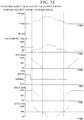
- FIG. 12 shows a command value adjustment amount output by the command value adjusting module 113B to the driving assistance subsystems CDM, BRC, DRCC, and SATC based on the command value output by the driving assistance subsystem PA.
- the driving assistance subsystem PA receives the "target steering angle" as a parameter together with the steering request SRI.
- the command value V output by the driving assistance subsystem PA is obtained by converting the target steering angle into the current command value for the electric motor 30 and then calculating the moving average of the absolute value to calculate the ratio (%) with the maximum output current. By the above calculation, the displacement of the command value V becomes gentle, and it is possible to prevent the output command value adjustment amount from suddenly fluctuating.
- the command value adjusting module 113B gradually increases the output gain of the driving assistance subsystem DRCC at 50% / s, and finally outputs a command value adjustment amount with a gain of 100%.
- the command value adjusting module 113B gradually decreases the output gain of the driving assistance subsystem DRCC at 50% / s, and finally outputs a command value adjustment amount with a gain of 50%.
- the command value adjusting module 113B gradually increases the output gain of the driving assistance subsystem SATC at 50% / s, and finally outputs a command value adjustment amount with a gain of 100%.
- the command value adjusting module 113B gradually decreases or gradually increases the output gain of the driving assistance subsystem SATC at 50% / s, and finally outputs a command value adjustment amount with a gain of 50%.
- the command value adjusting module 113B gradually decreases the output gain of the driving assistance subsystem SATC at 50% / s, and finally outputs a command value adjustment amount with a gain of 0%.
- the command value adjusting module 113B does not output the command value adjustment amount for adjusting the command value to the driving assistance subsystems CDM and BRC.
- FIG. 13 is a command value adjustment amount output by the command value adjusting module 113B to the driving assistance subsystems CDM, BRC, DRCC, and SATC based on the command value output by the driving assistance subsystem LKA.
- the driving assistance subsystem LKA receives the "target torque" as a parameter together with the steering request SRI.
- the command value V output by the driving assistance subsystem LKA is obtained by converting the target torque into the current command value for the electric motor 30 and then calculating the moving average of the absolute value to calculate the ratio (%) with the maximum output current. By the above calculation, the displacement of the command value V becomes gentle, and it is possible to prevent the output command value adjustment amount from suddenly fluctuating.
- the command value adjusting module 113B gradually increases the output gain of the driving assistance subsystem BRC at 10% / s, and finally outputs a command value adjustment amount with a gain of 100%.
- the command value adjusting module 113B gradually decreases the output gain of the driving assistance subsystem BRC at 10% / s, and finally outputs a command value adjustment amount with a gain of 0%.
- the command value adjusting module 113B When the driving assistance subsystem LKA is started and the command value V of the driving assistance subsystem LKA becomes larger than 0%, the command value adjusting module 113B outputs a command value adjustment amount such that the drive mode of the driving assistance subsystem CDM is changed from "Sport mode” to "Normal mode” (process 1).
- the command value adjusting module 113B When the command value V of the driving assistance subsystem LKA becomes 0%, the command value adjusting module 113B outputs a command value adjustment amount such that the drive mode of the driving assistance subsystem CDM returns to "Sport mode" (process 2).
- the command value adjusting module 113B does not output the command value adjustment amount for adjusting the command value to the driving assistance subsystems DRCC and SATC.
- FIG. 14 is a command value adjustment amount output by the command value adjusting module 113B to the driving assistance subsystems CDM, BRC, DRCC, and SATC based on the command value output by the driving assistance subsystem TJA.
- the driving assistance subsystem TJA receives the "target steering angle" as a parameter together with the steering request SRI.
- the command value V output by the driving assistance subsystem TJA is obtained by converting the target steering angle into the current command value for the electric motor 30 and then calculating the moving average of the absolute value to calculate the ratio (%) with the maximum output current. By the above calculation, the displacement of the command value V becomes gentle, and it is possible to prevent the output command value adjustment amount from suddenly fluctuating.
- the command value adjusting module 113B gradually increases the output gain of the driving assistance subsystem BRC at 10% / s, and finally outputs a command value adjustment amount with a gain of 100%.
- the command value adjusting module 113B gradually decreases the output gain of the driving assistance subsystem BRC at 10% / s, and finally outputs a command value adjustment amount with a gain of 0%.
- the command value adjusting module 113B When the driving assistance subsystem TJA is started and the command value V of the driving assistance subsystem TJA becomes larger than 0%, the command value adjusting module 113B outputs a command value adjustment amount such that the drive mode of the driving assistance subsystem CDM is changed from "Sport mode” to "Normal mode” (process 1).
- the command value adjusting module 113B When the command value V of the driving assistance subsystem TJA becomes 0%, the command value adjusting module 113B outputs a command value adjustment amount so that the drive mode of the driving assistance subsystem CDM returns to "Sport mode" (process 2).
- the command value adjusting module 113B gradually increases the output gain of the driving assistance subsystem DRCC at 10% / s, and finally outputs a command value adjustment amount with a gain of 100%.
- the command value adjusting module 113B gradually decreases the output gain of the driving assistance subsystem DRCC at 10% / s, and finally outputs a command value adjustment amount with a gain of 50%.
- the command value adjusting module 113B gradually increases the output gain of the driving assistance subsystem SATC at 10% / s, and finally outputs a command value adjustment amount with a gain of 100%.
- the command value adjusting module 113B gradually decreases or gradually increases the output gain of the driving assistance subsystem SATC at 10% / s, and finally outputs a command value adjustment amount with a gain of 50%.
- the command value adjusting module 113B gradually decreases the output gain of the driving assistance subsystem SATC at 10% / s, and finally outputs a command value adjustment amount with a gain of 0%.
- the adjustment method when adjusting the command value of the driving assistance subsystem 100 of the function belonging to the steering feeling improving function group (second function group), the adjustment method can be set in more detail based on the command value adjustment table. Therefore, the command value can be adjusted in more detail according to the command value output by the function belonging to the automatic driving function group (first function group). Specifically, when the magnitude (absolute value) of the command value output by the function belonging to the automatic driving function group (first function group) is large, the command value of the driving assistance subsystem 100 of the function belonging to the steering feeling improving function group (second function group) is gradually decreased to a smaller value.
- the target gain, gradual increase rate, and gradual decrease rate shown in Table 6 are examples, and are adjusted from various vehicle tests and the like. Further, the gradual increase rate and the gradual decrease rate may be changed depending on the magnitude (absolute value) of the command value output by the function belonging to the automatic driving function group (first function group). For example, the larger the magnitude (absolute value) of the command value output by the function belonging to the automatic driving function group (first function group), the faster the gradual decrease rate may be set, and the smaller the magnitude (absolute value) of the command value output by the function belonging to the automatic driving function group (first function group), the faster the gradual increase rate may be set.
- the power steering device 200 is a column assist type electric power steering device, but the mode of the electric power steering device is not limited to this.
- the electric power steering device may be a downstream type electric power steering device or a steer-by-wire type electric power steering device.
- the power steering device can also be applied to a hydraulic power steering device.
- the power steering device 200 has a steering assistance function that controls the drive of the electric motor 30 so that the steering torque Ts becomes smaller from the basic steering request SR0, but the mode of the power steering device is not limited to this.
- the power steering device may be a steering device that does not have a steering assistance function and is steered by an automatic driving function.
- the power steering device 200C according to the third embodiment is different from the first embodiment in that, when the driving assistance subsystem 100 of the function belonging to the steering feeling improvement function group (second function group) is started or stopped, the command value of the driving assistance subsystem 100 of the function belonging to the automatic driving function group (first function group) is adjusted.
- the power steering device 200C according to the third embodiment has the same configuration as the power steering device 200 according to the first embodiment, and only a part of the functions of the controller 34 is different from the power steering device 200.
- the functional block of the controller 34 includes a driving assistance subsystem 100 that receives steering requests (SRI, SR2, SR3) other than the basic steering request SR0, an arbitration module 110C, and a motor control module 120.
- the arbitration module 110C includes a priority determination module 111, a start-approval determination module 112, and a command value adjusting module 113C.
- the command value adjusting module 113 monitors the start / stop status of the driving assistance subsystem 100 of the function belonging to the automatic driving function group (first function group).
- the command value adjusting module 113C monitors the start / stop status of the driving assistance subsystem 100 of the function belonging to the steering feeling improving function group (second function group).
- the command value adjusting module 113C outputs a command value adjustment amount based on the command value adjustment table shown in Table 7 with respect to the command value output by the driving assistance subsystem 100 (driving assistance subsystem PA, LKA, TJA).
- the command value adjusting module 113C outputs a command value adjustment amount of "gradually decreasing the output gain at 50% / s to a gain of 0%" to the driving assistance subsystem LKA as shown in Table 7.
- the command value adjusting module 113C outputs a command value adjustment amount for adjusting the command value of the driving assistance subsystem 100 of the function belonging to the automatic driving function group (first function group), so that the command value output by the driving assistance subsystem 100 of the function belonging to the steering feeling improvement function group (second function group) to be started is prioritized.
- the command value adjusting module 113C outputs a command value adjustment amount to the driving assistance subsystem LKA so as to "decrease the output gain at 50% / s and finally set the gain to 0%".
- the command value adjusting module 113C When the driving assistance subsystem 100 of the function belonging to the steering feeling improving function group (second function group) is stopped, the command value adjusting module 113C outputs the command value adjustment amount based on the stop command value adjustment table shown in Table 8.
- the stop command value adjustment table has a command value adjustment amount for the driving assistance subsystem 100 (driving assistance subsystems PA, LKA, TJA) of the function belonging to the automatic driving function group (first function group), for each driving assistance subsystem 100 (driving assistance subsystems BRC, DRCC, STAC) of the function belonging to the steering feeling improving function group (second function group) to be stopped.
- the command value adjusting module 113C outputs a command value adjustment amount of "gradually increasing the output gain at 50% / s to finally make the gain 100%" to the driving assistance subsystem LKA as shown in Table 8.
- the command value adjusting module 113C When the driving assistance subsystem 100 of the function belonging to the steering feeling improvement function group (second function group) is stopped, the command value adjusting module 113C outputs a command value adjustment amount that restores the adjusted command value of the driving assistance subsystem 100 of the function belonging to the automatic driving function group (first function group).
- a plurality of driving assistance functions that can be operated at the same time can be operated in a coordinated manner.
- the functions belonging to the automatic driving function group (first function group) and the steering feeling improving function group (second function group) can be operated in coordination at the same time.
- the present invention can be applied to a steering device or the like having a driving assistance function classified into two or more types of functions such as a steering feeling improving function group and an automatic driving function group.
Landscapes
- Engineering & Computer Science (AREA)
- Chemical & Material Sciences (AREA)
- Combustion & Propulsion (AREA)
- Transportation (AREA)
- Mechanical Engineering (AREA)
- Physics & Mathematics (AREA)
- Mathematical Physics (AREA)
- Steering Control In Accordance With Driving Conditions (AREA)
Abstract
Description
- The present invention relates to a steering device such as a power steering device.
- The present application claims priority based on
Japanese Patent Application No. 2020-075728 filed on April 21, 2020 - The power steering device has a number of steering feeling improving functions such as driving track convergence control and self-alignment torque compensation, in addition to a steering assistance function that reduces the load on the driver by motor power.
- In recent years, vehicles equipped with automatic driving functions such as parking assistance, lane keeping assistance, and traffic jam driving assistance have been developed. The power steering device mounted on the vehicle equipped with the automatic driving function needs to operate without interfering with the driving assistance functions such as the steering feeling improving function and the automatic driving function.
- The steering system control device described in
Patent Document 1 arbitrates the steering request directed to the steering system according to the driving situation based on the priority. When a plurality of driving assistance functions are requested at the same time, the steering system control device described inPatent Document 1 selects and starts one of the driving assistance functions based on the priority. - [Patent Document 1]
United States Patent No. 8,406,956 - However, the steering system control device described in
Patent Document 1 can arbitrate and exclusively operate a plurality of driving assistance functions based on priority, but cannot operate a plurality of driving assistance functions at the same time in a coordinated manner. - Based on the above circumstances, it is an object of the present invention to provide a steering device capable of coordinating and operating a plurality of driving assistance functions.
- In order to solve the above problems, the present invention proposes the following means.
- The steering device according to the first aspect of the present invention includes a motor that assists or performs steering, and a controller that controls the motor. The controller receives a steering request for a plurality of assistance functions, selects a driving assistance function to be operated at the same time from the driving assistance functions for which the steering request was made, calculates a command value for the motor for each of the selected driving assistance functions, adjusts the command value based on a combination of the selected driving assistance function, and calculates a final command value for the motor using the adjusted command value.
- According to the steering device of the present invention, a plurality of driving assistance functions can be operated in a coordinated manner.
-
-
FIG. 1 is a schematic view showing a configuration of a power steering device according to a first embodiment of the present invention. -
FIG. 2 is a block diagram showing a configuration of an ECU of the power steering device. -
FIG. 3 is a block diagram showing a configuration of a controller of the ECU. -
FIG. 4 is a functional block diagram of the controller. -
FIG. 5 is a functional block diagram of a driving assistance subsystem, which is a function of the controller. -
FIG. 6 is a functional block diagram of an arbitration module, which is a function of the controller. -
FIG. 7 is a diagram showing input / output of a priority determination module, which is a function of the controller. -
FIG. 8 is a diagram showing input / output of a start-approval determination module, which is a function of the controller. -
FIG. 9 is a diagram showing input / output of a command value adjusting module, which is a function of the controller. -
FIG. 10 is a control flowchart of the controller that has received a steering request (SRI, SR2, SR3). -
FIG. 11 is a functional block diagram of the controller that has received a basic steering request. -
FIG. 12 is a command value adjustment amount output by a command value adjusting module based on a command value output by a driving assistance subsystem PA of a power steering device according to a second embodiment of the present invention. -
FIG. 13 is a command value adjustment amount output by the command value adjusting module based on the command value output by a driving assistance subsystem LKA of the power steering device. -
FIG. 14 is a command value adjustment amount output by the command value adjusting module based on the command value output by a driving assistance subsystem TJA of the power steering device. - A first embodiment of the present invention will be described with reference to
FIGS. 1 to 11 . -
FIG. 1 is a schematic view showing a configuration of a power steering device 200 according to the present embodiment. The power steering device 200 is a column assist type electric power steering device in which an electric motor and a reduction mechanism are arranged on a column portion (steering shaft). - As shown in
FIG. 1 , the power steering device (steering device) 200 includes asteering wheel 1 that is a steering member for steering a vehicle, asteering mechanism 2 that steers the steering wheels in conjunction with the rotation of thesteering wheel 1, and asteering assistance mechanism 3 that assists the steering of the driver. - The
steering mechanism 2 includes a steering shaft (column shaft, steering wheel shaft) 20 connected to thesteering wheel 1, asteering angle sensor 20a that detects the steering angle of thesteering wheel 1, auniversal joint 24, anintermediate shaft 25, apinion rack mechanism 26,tie rods hub units - The
steering shaft 20 is connected to the steering wheel via theuniversal joint 24, theintermediate shaft 25, thepinion rack mechanism 26, thetie rods hub units steering shaft 20 is provided with atorque sensor 29. Thetorque sensor 29 is used to calculate the steering torque (steering torque) Ts. - The
pinion rack mechanism 26 has a pinion and a rack (not shown in the figure). - The pinion is connected to the
intermediate shaft 25 and rotates in conjunction with the rotation of theintermediate shaft 25. - The rack extends linearly along the left-right direction (direction orthogonal to the straight-ahead direction) of the automobile. The rack meshes with the pinion near the axial middle of the rack. The pinion and rack translate the rotation of the pinion into the axial movement of the rack. Steering wheels are steered by moving the rack in the axial direction.
- When the
steering wheel 1 is steered (rotated) by the driver, the rotation of thesteering wheel 1 is transmitted to the pinion via thesteering shaft 20 and theintermediate shaft 25. Then, the rotation of the pinion is converted into the axial movement of the rack. Thetie rods hub units pinion rack mechanism 26 move in the axial direction of the rack, and the steering wheels connected to thehub units - As shown in
FIG. 1 , thesteering assistance mechanism 3 includes anelectric motor 30, areduction mechanism 31, avehicle speed sensor 32 that detects vehicle speed, and an ECU (controller) 33. - The
electric motor 30 is an electric motor that assists the steering force of thesteering wheel 1, and is, for example, a three-phase brushless motor. Theelectric motor 30 is connected to thesteering shaft 20 via thereduction mechanism 31. - The
reduction mechanism 31 includes a worm gear mechanism having aworm 31a and aworm wheel 31b that meshes with theworm 31a. Theworm 31a is rotationally driven by theelectric motor 30. Further, theworm wheel 31b is integrally rotatably connected to thesteering shaft 20. Theworm wheel 31b is rotationally driven by theworm 31a. - The
vehicle speed sensor 32 is a sensor that detects the vehicle speed Vel. Thevehicle speed sensor 32 outputs the detected vehicle speed Vel to theECU 33. -
FIG. 2 is a block diagram showing the configuration of theECU 33. - As shown in
FIG. 2 , the ECU (controller) 33 includes acontroller 34 and amotor drive circuit 35. -
FIG. 3 is a block diagram showing a configuration of thecontroller 34. - As shown in
FIG. 3 , thecontroller 34 is a program-executable device (computer) including a CPU (Central Processing Unit) 36, amemory 37, astorage unit 38, and an input /output controller 39. By executing a predetermined program, it functions as a plurality of functional blocks such as amotor control module 120 described later. At least a part of the functions of thecontroller 34 may be configured by a dedicated logic circuit or the like. - The
storage unit 38 is a non-volatile recording medium that stores the above-mentioned program and necessary data. Thestorage unit 38 is composed of, for example, a ROM, a hard disk, or the like. The program recorded in thestorage unit 38 is read into thememory 37 and executed by theCPU 36. - The input /
output controller 39 receives input data from thevehicle speed sensor 32, the rotation angle sensor of theelectric motor 30, the external vehicle system, and the like. Further, when theCPU 36 controls thevehicle speed sensor 32 and theelectric motor 30, the input /output controller 39 generates a control signal for thevehicle speed sensor 32 and theelectric motor 30 based on an instruction of theCPU 36. - The
motor drive circuit 35 is an inverter or the like that drives theelectric motor 30. Themotor drive circuit 35 uses, for example, a FET (field effect transistor) as a drive element, and is composed of a bridge circuit of the FET. Further, themotor drive circuit 35 includes a motor current detection circuit. -
FIG. 4 is a functional block diagram of thecontroller 34. - The
controller 34 receives steering requests related to a plurality of driving assistance functions. The steering request is a control request related to steering such as steering angle and steering torque. Thecontroller 34 receives a basic steering request SR0 related to the steering assistance function, a first steering request SRI related to a function belonging to the automatic driving function group (first function group), a second steering request SR2 related to a function belonging to the steering feeling improving function group (second function group), and a third steering request SR3 related to other functions. - The
controller 34 receives the relevant parameters along with the steering request. The parameters relate to a function corresponding to a steering requirement, for example, a target steering angle, an additional torque amount, a vehicle speed, a wheel speed, a steering angle, a steering angular velocity, a steering vibration pattern, an operation mode, and the like. - The functional block of the
controller 34 includes a drivingassistance subsystem 100 that receives steering requests (SRI, SR2, SR3) other than the basic steering request SR0, anarbitration module 110, and amotor control module 120. The basic steering request SR0 is directly received by themotor control module 120. - The steering assistance function is a basic function of the power steering device 200 that assists the steering of the operator. The
controller 34, which has received the steering request by the steering assistance function, calculates a current command value of an assist (steering assistance) command based on the steering torque Ts detected by thetorque sensor 29 and the vehicle speed Vel detected by thevehicle speed sensor 32, further calculates a voltage command value with compensation or the like, and controls the inverter that drives theelectric motor 30. - The automatic driving function group (first function group) includes, for example, a parking assistance function (Parking Assist), a lane keeping assistance function (Lane Keep Assist), a traffic jam driving assistance function (Traffic Jam Assist), and the like. The steering request SRI relating to the function (first driving assistance function) belonging to the automatic driving function group (first function group) is a steering request by these automatic driving functions.
- The steering feeling improving function group (second function group) includes, for example, a drive mode switching function (Change Drive Mode), a banked road compensation function (Banked Road Compensation), a driving track convergence control function (Drive Route Convergence Control), and a self-alignment torque compensation (Self Alignment Torque Compensation), and the like. The steering request SR2 relating to the function (second driving assistance function) belonging to the steering feeling improving function group (second function group) is a steering request by these steering feeling improving functions. The drive mode switching function is a function for switching the steering feeling by preparing a plurality of settings in which the magnitude of the steering assistance command for the steering torque is different. The banked road compensation function is a function to output a steering assistance force for reducing the steering wheel holding force (load) of the driver when driving straight on the bank (cant) for drainage. The driving track convergence control function outputs a damping compensation value for converging the yaw rate of the vehicle to ensure vehicle stability. The self-alignment torque compensation adjusts the steering reaction force due to the self-aligning torque from the tire to improve the steering feeling.
- Other functions (third function group) are, for example, a lane departure warning function (Lane Departure Warning), and are steering driving functions that do not belong to the steering assistance function, the automatic driving function group (first function group), and the steering feeling improving function group (second function group). In the present embodiment, the third steering request SR3 regarding other functions (third function group) is a steering request by the lane departure warning function (Lane Departure Warning).
- The driving
assistance subsystem 100 receives steering requests (SRI, SR2, SR3) other than the basic steering request SR0, converts the received steering request into a command value for theelectric motor 30, and outputs the received steering request to themotor control module 120. The command value for theelectric motor 30 is a current command value, a steering torque, a steering angle, a start command for a predetermined function, and the like. - The driving
assistance subsystem 100 is provided independently for each function (function of automatic driving function group, function of steering feeling improving function group, and other functions). In the present embodiment, the drivingassistance subsystem 100 is provided for each of the eight functions shown in Table 1. The names of the drivingassistance subsystems 100 for each function are shown in Table 1.[Table 1] FUNCTION NAME NAME OF DRIVING ASSISTANCE SUBSYSTEM 100PARKING ASSIST FUNCTION (PARKING ASSIST) DRIVING ASSISTANCE SUBSYSTEM PA LANE KEEP ASSIST FUNCTION (LANE KEEP ASSIST) DRIVING ASSISTANCE SUBSYSTEM LKA TRAFFIC JAM ASSIST FUNCTION (TRAFFIC JAM ASSIST) DRIVING ASSISTANCE SUBSYSTEM TJA CHANGE DRIVE MODE FUNCTION (CHANGE DRIVE MODE) DRIVING ASSISTANCE SUBSYSTEM CDM BANKED ROAD COMPENSATION FUNCTION (BANKED ROAD COMPENSATION) DRIVING ASSISTANCE SUBSYSTEM BRC DRIVE ROUTE CONVERGENCE CONTROL FUNCTION (DRIVE ROUTE CONVERGENCE CONTROL) DRIVING ASSISTANCE SUBSYSTEM DRCC SELF ALIGNMENT TORQUE COMPENSATION FUNCTION (SELF ALIGNMENT TORQUE COMPENSATION) DRIVING ASSISTANCE SUBSYSTEM SATC LANE DEPARTURE WARNING FUNCTION (LANE DEPARTURE WARNING) DRIVING ASSISTANCE SUBSYSTEM LDW -
FIG. 5 is a functional block diagram of the drivingassistance subsystem 100. - The driving
assistance subsystem 100 includes astart determination module 101, a drivingassistance module 102, and a commandvalue output module 103. - The
start determination module 101 determines whether or not it is necessary to start the drivingassistance subsystem 100 from steering requests and parameters received from an external vehicle system or the like. When thestart determination module 101 determines that it is necessary to operate the drivingassistance subsystem 100, it further inquires thearbitration module 110 whether or not the drivingassistance subsystem 100 can be started, and determines whether or not the drivingassistance subsystem 100 can be started. When thearbitration module 110 determines that the drivingassistance subsystem 100 can be started, thestart determination module 101 starts the drivingassistance module 102. - The driving
assistance module 102 performs the function assigned to the drivingassistance subsystem 100. The drivingassistance module 102 calculates and outputs a command value for theelectric motor 30 based on the driving assistance function. The command value is sent to the commandvalue output module 103 and thearbitration module 110. - The command
value output module 103 adjusts and outputs the command value for theelectric motor 30 calculated by the drivingassistance module 102 based on the command value adjustment amount (gain or gain change speed) instructed from thearbitration module 110. For example, when the instructed gain is "50%", the commandvalue output module 103 adjusts the command value for theelectric motor 30 calculated by the drivingassistance module 102 to 50% and outputs the command value. - In the present embodiment, for the driving assistance subsystem 100 (driving assistance subsystem PA, LKA, TJA) of the function belonging to the automatic driving function group (first function group), the command value adjustment amount is not instructed from the
arbitration module 110. - The command
value output module 103 may have a limiter module that performs limiting processing so that the command value or the change speed of the command value with respect to theelectric motor 30 falls within a safe range, and a gradual change module that changes the command value at a specified rate of change so that the command value does not change suddenly at the start or end of operation. -
FIG. 6 is a functional block diagram of thearbitration module 110. - The
arbitration module 110 includes apriority determination module 111, a start-approval determination module 112, and a commandvalue adjusting module 113. - When the
priority determination module 111 newly receives a start request from a plurality of drivingassistance subsystems 100 in a predetermined period, thepriority determination module 111 determines the drivingassistance subsystem 100 as a startable candidate. -
FIG. 7 is a diagram showing input / output of thepriority determination module 111. - The input of the
priority determination module 111 is a start request from a plurality of drivingassistance subsystems 100. The output of thepriority determination module 111 is the drivingassistance subsystem 100 determined to be startable. - The
priority determination module 111 determines the drivingassistance subsystem 100 as a startable candidate based on the priority table shown in Table 2. The drivingassistance subsystem 100, which has a smaller value indicating priority, has a higher priority. In this embodiment, the driving assistance subsystem TJA has the highest priority.[Table 2] DRIVING ASSISTANCE SUBSYSTEM 100PRIORITY DRIVING ASSISTANCE SUBSYSTEM PA 3 DRIVING ASSISTANCE SUBSYSTEM LKA 2 DRIVING ASSISTANCE SUBSYSTEM TJA 1 DRIVING ASSISTANCE SUBSYSTEM CDM - DRIVING ASSISTANCE SUBSYSTEM BRC - DRIVING ASSISTANCE SUBSYSTEM DRCC - DRIVING ASSISTANCE SUBSYSTEM SATC - DRIVING ASSISTANCE SUBSYSTEM LDW - - When receiving a new start request from a plurality of driving
assistance subsystems 100 in a predetermined period, thepriority determination module 111 determines the drivingassistance subsystem 100 having the highest priority among the drivingassistance subsystems 100 having the priority as a startable candidate. - For example, when newly receiving a start request from the driving assistance subsystem TJA and the driving assistance subsystem LKA in a predetermined period, the
priority determination module 111 determines the driving assistance subsystem TJA having a high priority as a startable candidate. - The driving assistance subsystem 100 (driving assistance subsystems PA, LKA, TJA) of the function belonging to the automatic driving function group (first function group) has a priority, and is exclusively selected as a startable candidate by the
priority determination module 111. - The driving
assistance subsystem 100 having no priority is not subject to the startable candidate determination based on the priority. When receiving a new start request from the drivingassistance subsystem 100 having no priority, thepriority determination module 111 always determines the drivingassistance subsystem 100 as a startable candidate. Therefore, the startable candidates determined by thepriority determination module 111 may be a plurality of drivingassistance subsystems 100. - The driving assistance subsystem 100 (driving assistance subsystem CDM, BRC, DRCC, SATC) of the function belonging to the steering feeling improving function group (second function group) and the driving assistance subsystem 100 (driving assistance subsystem LDW) of the function belonging to other functions (third function group) do not have priority, and are not subject to startable candidate determination based on priority. When a new start request is received from the driving
assistance subsystem 100 of the functions belonging to the steering feeling improving function group (second function group) and other functions (third function group), the drivingassistance subsystem 100 is always determined to be a startable candidate. - The start-
approval determination module 112 determines whether or not the drivingassistance subsystem 100 determined by thepriority determination module 111 to be a startable candidate can be started in consideration of the operation status of the otherdriving assistance subsystems 100. The operation status of the drivingassistance subsystem 100 is either "operating" or "stopping". -
FIG. 8 is a diagram showing input / output of the start-approval determination module 112. - The input of the start-
approval determination module 112 is the operation status (input 1) of all the drivingassistance subsystems 100 and the driving assistance subsystem 100 (input 2) determined to be startable, which is the output of thepriority determination module 111. The output of the start-approval determination module 112 is the start-approval of the drivingassistance subsystem 100 determined to be startable. - The start-
approval determination module 112 determines the startabledriving assistance subsystem 100 based on the start-approval determination table shown in Table 3. In Table 3, "possible" indicates that the drivingassistance subsystem 100 can be started. "Impossible" indicates that the drivingassistance subsystem 100 cannot be started. "-" Indicates that the drivingassistance subsystem 100 is already in operation and does not determine whether or not it can be started.

- The start-approval determination table has entries corresponding to the combination of the operation status (input 1) of all the driving
assistance subsystems 100. Since there are eight types of drivingassistance subsystems 100 in this embodiment, the start-approval determination table has 256 entries. Any one entry is selected based on the operation status (input 1) of all drivingassistance subsystems 100. - The start-approval determination table has the start-approval (output) of the driving
assistance subsystem 100 for each entry. Whether or not to start the operation corresponding to the driving assistance subsystem 100 (input 2) determined to be startable is selected and output. The start-approval determined by the start-approval determination module 112 is sent to thestart determination module 101. - For example, when the driving assistance subsystems TJA, SATC, and LDW are input as the
input 2 in the operation status (input 1) of the drivingassistance subsystem 100 as shown in theentry number 2 in Table 3, "possible" for the driving assistance subsystem TJA, "possible" for the driving assistance subsystem SATC, and "possible" for the driving assistance subsystem LDW are output, based on the start-approval determination table. - For example, when the driving assistance subsystems TJA, SATC, and LDW are input as the
input 2 in the operation status (input 1) of the drivingassistance subsystem 100 as shown in the entry number 4 of Table 3, "impossible" for the driving assistance subsystem TJA, "possible" for the driving assistance subsystem SATC, and "possible" for the driving assistance subsystem LDW are output, based on the start-approval determination table. - When the operation status of the driving assistance subsystem 100 (driving assistance subsystems PA, LKA, TJA) of the function belonging to the automatic driving function group (first function group) is "operating", whether or not the driving
assistance subsystem 100 of other functions belonging to the automatic driving function group (first function group) can be started is "impossible". That is, two or more functions belonging to the automatic driving function group (first function group) are not performed at the same time. - Whether or not the functions can be started for the driving assistance subsystem 100 (driving assistance subsystem CDM, BRC, DRCC, SATC) belonging to the steering feeling improving function group (second function group) is all "possible" unless its own function is "operating".
- Whether or not the functions can be started for the driving assistance subsystem 100 (driving assistance subsystem LDW) belonging to the other functions (third function group) is "possible" unless the driving assistance subsystem PA or its own function is "operating".
- The command
value adjusting module 113 monitors the command value and the start / stop status output by the driving assistance subsystem 100 (driving assistance subsystems PA, LKA, TJA) of the function belonging to the automatic driving function group (first function group), and determines the command value adjustment amount for the driving assistance subsystem 100 (driving assistance subsystem CDM, BRC, DRCC, SATC) of the function belonging to the steering feeling improving function group (second function group). -
FIG. 9 is a diagram showing input / output of the commandvalue adjusting module 113. - The input of the command
value adjusting module 113 is command value or start / stop status output by the driving assistance subsystem 100 (driving assistance subsystems PA, LKA, TJA) of the function belonging to the automatic driving function group (first function group). The output of the commandvalue adjusting module 113 is a command value adjustment amount for the driving assistance subsystem 100 (driving assistance subsystem CDM, BRC, DRCC, SATC) of the function belonging to the steering feeling improving function group (second function group). - The command
value adjusting module 113 outputs a command value adjustment amount based on the start-up command value adjustment table shown in Table 4 when the drivingassistance subsystem 100 of the function belonging to the automatic driving function group (first function group) is started. Here, the values shown in Table 4 are examples and are adjusted according to the characteristics of the vehicle.

- The start-up command value adjustment table has a command value adjustment amount for the driving assistance subsystem 100 (driving assistance subsystem CDM, BRC, DRCC, SATC) of the function belonging to the steering feeling improving function group (second function group), for each driving assistance subsystem 100 (driving assistance subsystem PA, LKA, TJA) of the function belonging to the automatic driving function group (first function group) to be started.
- For example, when the driving assistance subsystem TJA is started, the command
value adjusting module 113 outputs the command value adjustment amount shown in the bottom line of Table 4 to the driving assistance subsystems CDM, BRC, DRCC, and SATC. Specifically, a command value adjustment amount of "gradually decreasing the command value at 10% / s until the command value reaches 0%" is output to the driving assistance subsystem BRC. Further, a command value adjustment amount of "changing the drive mode to the Normal mode" is output to the driving assistance subsystem CDM. Further, for the driving assistance subsystems DRCC and SATC, a command value adjustment amount of "gradually decreasing the command value at 10% / s until the command value reaches 50%" is output. - The command
value adjusting module 113 outputs a command value adjustment amount for adjusting the command value of the drivingassistance subsystem 100 of the function belonging to the steering feeling improving function group (second function group), so that the command value output by the drivingassistance subsystem 100 of the function belonging to the started automatic driving function group (first function group) is prioritized. The commandvalue adjusting module 113 outputs, for example, a command value adjustment amount for reducing the command value to the driving assistance subsystems BRC, DRCC, and SATC. The commandvalue adjusting module 113 outputs a command value adjustment amount to the driving assistance subsystem CDM so as to change the drive mode to the normal mode so that the specific function is invalidated. - The command
value adjusting module 113 outputs a command value adjustment amount based on the stop command value adjustment table shown in Table 5 when the drivingassistance subsystem 100 of the function belonging to the automatic driving function group (first function group) is stopped. Here, the values shown in Table 5 are examples and are adjusted according to the characteristics of the vehicle.
- The stop command value adjustment table has a command value adjustment amount for the driving assistance subsystem 100 (driving assistance subsystem CDM, BRC, DRCC, SATC) of the function belonging to the steering feeling improving function group (second function group), for each driving assistance subsystem 100 (driving assistance subsystem PA, LKA, TJA) of the function belonging to the automatic driving function group (first function group) to be stopped.
- For example, when the driving assistance subsystem TJA is stopped, the command
value adjusting module 113 outputs the command value adjustment amount shown in the bottom line of Table 5 to the driving assistance subsystems CDM, BRC, DRCC, and SATC. Specifically, for the driving assistance subsystems BRC, DRCC, and SATC, a command value adjustment amount of "gradually increasing the command value at 10% / s until the command value reaches 100%" is output. Further, the command value adjustment amount of "changing the drive mode to the original drive mode before changing to the normal mode" is output to the driving assistance subsystem CDM. - When the driving
assistance subsystem 100 of the function belonging to the automatic driving function group (first function group) is stopped, the commandvalue adjusting module 113 outputs a command value adjustment amount that restores the adjusted command value of the drivingassistance subsystem 100 of the function belonging to the steering feeling improving function group (second function group). - The
motor control module 120 receives a command value output by the drivingassistance subsystem 100, and outputs a signal for driving theelectric motor 30. As shown inFIG. 4 , themotor control module 120 includes atorque control module 121 and acurrent control module 122. - The
torque control module 121 adds the command value calculated based on the steering torque Ts output by thetorque sensor 29 and the command value output by each drivingassistance subsystem 100 and converts the command value into a current command value. - The
current control module 122 performs processing such as limiting the maximum value of the current command value output by thetorque control module 121, converts it into a signal for driving theelectric motor 30, and outputs the signal. - Next, the
controller 34 that has received the steering request (SRI, SR2, SR3) will be described in detail.FIG. 10 is a control flowchart of thecontroller 34 that has received the steering request (SRI, SR2, SR3). - As shown in
FIG. 10 , when thecontroller 34 is started, thecontroller 34 starts control after performing initialization (step S10). Next, thecontroller 34 performs step S11. - In step S11, the
controller 34 receives the steering request (SRI, SR2, SR3). Next, in step S12, thecontroller 34 determines whether or not the predetermined period has elapsed. When the predetermined period has not elapsed, thecontroller 34 performs step S11 and continues to receive the steering request. When the predetermined period has elapsed, thecontroller 34 performs step S13. - In step S13, the
controller 34 determines whether there is a drivingassistance subsystem 100 that needs to be started by thestart determination module 101. When there is no drivingassistance subsystem 100 that needs to be started, thecontroller 34 performs step S11 again. When there is a drivingassistance subsystem 100 that needs to be started, thecontroller 34 performs step S14. For example, suppose that in step S13, it is determined that the driving assistance subsystems PA, LKA, TJA, SATC, and LDW can be started. - In step S14, the
controller 34 determines the candidates for the functions that can be started at the same time by thepriority determination module 111. The driving assistance subsystems PA, LKA, and TJA have priorities, and are exclusively selected as startable candidates by thepriority determination module 111. In this embodiment, the driving assistance subsystem TJA has the highest priority. Therefore, the driving assistance subsystem TJA is determined to be a startable candidate, and the driving assistance subsystems PA and LKA are not determined to be startable candidates. The driving assistance subsystem SATC and the driving assistance subsystem LDW do not have priority and are not subject to the startable candidate determination based on the priority, and both are determined to be startable candidates. - . In step S14, the
controller 34 determines that the driving assistance subsystems TJA, SATC, and LDW are startable candidates. Next, thecontroller 34 performs step S15. - In step S15, the
controller 34 determines whether or not the drivingassistance subsystem 100 determined to be a startable candidate can be started in consideration of the operation status of the otherdriving assistance subsystems 100 by the start-approval determination module 112. Thecontroller 34 determines that the driving assistance subsystems TJA, SATC, and LDW can be started based on the start-approval determination table. Next, thecontroller 34 performs step S16. - In step S16, the
controller 34 causes the drivingassistance module 102 of the driving assistance subsystems TJA, SATC, and LDW to calculate a command value for theelectric motor 30 based on each function. Next, thecontroller 34 performs step S17. - In step S17, the
controller 34 determines the command value adjustment amount for the driving assistance subsystems CDM, BRC, DRCC, and SATC by the commandvalue adjusting module 113. Thecontroller 34 outputs the command value adjustment amount for the driving assistance subsystems CDM, BRC, DRCC, and SATC when the driving assistance subsystem TJA is started, based on the start-up command value adjustment table shown in Table 4. Next, thecontroller 34 performs step S18. - In step S18, the
controller 34 adjusts and outputs the command value for theelectric motor 30 calculated by the drivingassistance module 102 based on the command value adjustment amount by the commandvalue output module 103. Next, thecontroller 34 performs step S19. - In step S19, the
controller 34 receives the command value output by the drivingassistance subsystem 100 by themotor control module 120, and calculates the command value to be final (final command value) for theelectric motor 30. Next, thecontroller 34 performs step S20. - In step S20, the
controller 34 determines whether to end the control. When the control is not ended, thecontroller 34 performs step S11. When ending the control, the controller performs step S21. -
FIG. 11 is a functional block diagram of themotor control module 120 in thecontroller 34 that has received the basic steering request SR0. The steering torque Ts detected by thetorque sensor 29 and the vehicle speed Vel detected by thevehicle speed sensor 32 are input to the current commandvalue calculation unit 41 that calculates the current command value Iref1. The current commandvalue calculation unit 41 calculates the current command value Iref1, which is the control target value of the current supplied to theelectric motor 30, by using the assist map or the like based on the input steering torque Ts and the vehicle speed Vel. - The current command value Iref1 is input to the current limiting
unit 43 in thecurrent control module 122 via the addingunit 42A, the current command value Ireffm whose maximum current is limited is input to thesubtracting unit 42B, and the deviation I (Irefm-Im) from the fed-back motor current value Im is calculated. The deviation I is input to the PI (proportional integration)controller 45 in order to improve the characteristics of the steering operation. - The voltage control value Vref PI-controlled by the
PI controller 45 is input to thePWM controller 46 together with the modulation signal (carrier) CF. ThePWM controller 46 calculates the duty and PWM-drives theelectric motor 30 via themotor drive circuit 35 by the PWM signal. - The motor current value is detected by the motor current detecting means, input to the
subtracting unit 42B, and fed back. In the case of a three-phase brushless motor, thePWM controller 46 is composed of a duty calculation unit, which calculates a PWM duty value D for three phases according to a predetermined formula, and a gate drive unit that drives the gate of the FET as a drive element with a PWM duty value D and turns on / off by compensating for dead time. Themotor drive circuit 35 is composed of, for example, a three-phase bridge including an upper and lower arms composed of a U-phase upper FET and a lower FET, and theelectric motor 30 is driven by turning on / off each FET at the PWM duty value D. - The output from each driving
assistance subsystem 100 is input to the addingunit 42A. For example, when the driving assistance subsystem SATC is started, the steering reaction force due to the self-aligning torque from the tire is compensated. - When the driver steers the
steering wheel 1, thetorque sensor 29 detects the steering torque Ts. Upon receiving the basic steering request SR0, theECU 33 controls the drive of theelectric motor 30 so that the steering torque Ts becomes smaller based on the steering torque Ts and the vehicle speed Vel detected by thevehicle speed sensor 32. As a result, theworm 31a is rotationally driven by theelectric motor 30 controlled by theECU 33. Theelectric motor 30 can assist the driver in steering by rotationally driving theworm 31a. - The
controller 34, which has received the steering request (SRI, SR2, SR3) in accordance with the basic steering request SR0, adds the command value output by the drivingassistance subsystem 100 to the command value for theelectric motor 30 calculated based on the basic steering request SR0, to calculate and output the command value (final command value) for the finalelectric motor 30. - The
controller 34 may replace the command value for theelectric motor 30 calculated based on the basic steering request SR0 by the command value output by the driving assistance subsystem 100 (driving assistance subsystems PA, LKA, TJA) of the function belonging to the automatic driving function group (first function group). In this case, regardless of the steering of thesteering wheel 1 of the driver, steering by a function belonging to the automatic driving function group (first function group) is performed. - According to the power steering device 200 of the present embodiment, a plurality of driving assistance functions that can be operated at the same time can be operated in a coordinated manner. In particular, the power steering device 200 outputs a command value adjustment amount for adjusting the command value of the driving
assistance subsystem 100 of the function belonging to the steering feeling improving function group (second function group), so that the command value output by theoperation assistance subsystem 100 of the function belonging to the started automatic operation function group (first function group) is prioritized. Further, when the drivingassistance subsystem 100 of the function belonging to the automatic driving function group (first function group) is stopped, a command value adjustment amount that restores the adjusted command value of the drivingassistance subsystem 100 of the function belonging to the steering feeling improving function group (second function group) is output. Therefore, the function belonging to the automatic driving function group (first function group) can be appropriately coordinated with the function belonging to the steering feeling improving function group (second function group) that the power steering device 200 conventionally has. - According to the power steering device 200 of the present embodiment, when adjusting the command value of the driving
assistance subsystem 100 of the function belonging to the steering feeling improving function group (second function group), the command value adjustment method can be set in advance according to the function, based on the start command value adjustment table and the stop command value adjustment table. Therefore, when a function belonging to the automatic driving function group (first function group) is started or stopped, the command value can be adjusted according to the function. - Although the first embodiment of the present invention has been described in detail with reference to the drawings, the specific configuration is not limited to this embodiment, and includes design changes and the like within a range that does not deviate from the gist of the present invention. In addition, the components shown in the above-described embodiments and modifications can be appropriately combined and configured.
- A second embodiment of the present invention will be described with reference to
FIGS. 12 to 14 . In the following description, the same reference numerals will be given to the configurations common to those already described, and a duplicate description will be omitted. - The power steering device 200B according to the second embodiment has the same configuration as the power steering device 200 according to the first embodiment, and only a part of the functions of the
controller 34 is different from the power steering device 200. - In the second embodiment, the functional block of the
controller 34 includes a drivingassistance subsystem 100 that receives steering requests (SRI, SR2, SR3) other than the basic steering request SR0, an arbitration module 110B, and amotor control module 120. - The arbitration module 110B includes a
priority determination module 111, a start-approval determination module 112, and a command value adjusting module 113B. - The command value adjusting module 113B monitors the command value and the start / stop status output by the driving assistance subsystem 100 (driving assistance subsystems PA, LKA, TJA) of the function belonging to the automatic driving function group (first function group), and determines the command value adjustment amount for the driving assistance subsystem 100 (driving assistance subsystem CDM, BRC, DRCC, SATC) of the function belonging to the steering feeling improving function group (second function group).
- In the first embodiment, the command
value adjusting module 113 monitors the start / stop status of the driving assistance subsystem 100 (driving assistance subsystem PA, LKA, TJA) of the function belonging to the automatic driving function group (first function group). On the other hand, in the second embodiment, the command value adjusting module 113B monitors the command value output by the driving assistance subsystem 100 (driving assistance subsystems PA, LKA, TJA) of the function belonging to the automatic driving function group (first function group). - The command value adjusting module 113B outputs a command value adjustment amount based on the command value adjustment table shown in Table 6 with respect to the command value output by the driving assistance subsystem 100 (driving assistance subsystems PA, LKA, TJA).


- When the command value output by the driving assistance subsystem 100 (driving assistance subsystems PA, LKA, TJA) corresponds to the conditions of the command value adjustment table, the command value adjusting module 113B outputs the command value adjustment amount for the driving assistance subsystem 100 (driving assistance subsystems CDM, BRC, DRCC, SATC) of the function belonging to the steering feeling improvement function group (second function group), based on the command value adjustment table.
-
FIG. 12 shows a command value adjustment amount output by the command value adjusting module 113B to the driving assistance subsystems CDM, BRC, DRCC, and SATC based on the command value output by the driving assistance subsystem PA. - The driving assistance subsystem PA receives the "target steering angle" as a parameter together with the steering request SRI. The command value V output by the driving assistance subsystem PA is obtained by converting the target steering angle into the current command value for the
electric motor 30 and then calculating the moving average of the absolute value to calculate the ratio (%) with the maximum output current. By the above calculation, the displacement of the command value V becomes gentle, and it is possible to prevent the output command value adjustment amount from suddenly fluctuating. - When the command value V of the driving assistance subsystem PA is within 5%, the command value adjusting module 113B gradually increases the output gain of the driving assistance subsystem DRCC at 50% / s, and finally outputs a command value adjustment amount with a gain of 100%.
- When the command value V of the driving assistance subsystem PA is larger than 5%, the command value adjusting module 113B gradually decreases the output gain of the driving assistance subsystem DRCC at 50% / s, and finally outputs a command value adjustment amount with a gain of 50%.
- When the command value V of the driving assistance subsystem PA is within 10%, the command value adjusting module 113B gradually increases the output gain of the driving assistance subsystem SATC at 50% / s, and finally outputs a command value adjustment amount with a gain of 100%.
- When the command value V of the driving assistance subsystem PA is 20% or less and larger than 10%, the command value adjusting module 113B gradually decreases or gradually increases the output gain of the driving assistance subsystem SATC at 50% / s, and finally outputs a command value adjustment amount with a gain of 50%.
- When the command value V of the driving assistance subsystem PA is larger than 20%, the command value adjusting module 113B gradually decreases the output gain of the driving assistance subsystem SATC at 50% / s, and finally outputs a command value adjustment amount with a gain of 0%.
- Regardless of the command value V of the driving assistance subsystem PA, the command value adjusting module 113B does not output the command value adjustment amount for adjusting the command value to the driving assistance subsystems CDM and BRC.
-
FIG. 13 is a command value adjustment amount output by the command value adjusting module 113B to the driving assistance subsystems CDM, BRC, DRCC, and SATC based on the command value output by the driving assistance subsystem LKA. - The driving assistance subsystem LKA receives the "target torque" as a parameter together with the steering request SRI. The command value V output by the driving assistance subsystem LKA is obtained by converting the target torque into the current command value for the
electric motor 30 and then calculating the moving average of the absolute value to calculate the ratio (%) with the maximum output current. By the above calculation, the displacement of the command value V becomes gentle, and it is possible to prevent the output command value adjustment amount from suddenly fluctuating. - When the command value V of the driving assistance subsystem LKA is 0%, the command value adjusting module 113B gradually increases the output gain of the driving assistance subsystem BRC at 10% / s, and finally outputs a command value adjustment amount with a gain of 100%.
- When the command value V of the driving assistance subsystem LKA is larger than 0%, the command value adjusting module 113B gradually decreases the output gain of the driving assistance subsystem BRC at 10% / s, and finally outputs a command value adjustment amount with a gain of 0%.
- For example, suppose that the user sets the drive mode of the driving assistance subsystem CDM to "Sport mode".
- When the driving assistance subsystem LKA is started and the command value V of the driving assistance subsystem LKA becomes larger than 0%, the command value adjusting module 113B outputs a command value adjustment amount such that the drive mode of the driving assistance subsystem CDM is changed from "Sport mode" to "Normal mode" (process 1).
- When the command value V of the driving assistance subsystem LKA becomes 0%, the command value adjusting module 113B outputs a command value adjustment amount such that the drive mode of the driving assistance subsystem CDM returns to "Sport mode" (process 2).
- Regardless of the command value V of the driving assistance subsystem LKA, the command value adjusting module 113B does not output the command value adjustment amount for adjusting the command value to the driving assistance subsystems DRCC and SATC.
-
FIG. 14 is a command value adjustment amount output by the command value adjusting module 113B to the driving assistance subsystems CDM, BRC, DRCC, and SATC based on the command value output by the driving assistance subsystem TJA. - The driving assistance subsystem TJA receives the "target steering angle" as a parameter together with the steering request SRI. The command value V output by the driving assistance subsystem TJA is obtained by converting the target steering angle into the current command value for the
electric motor 30 and then calculating the moving average of the absolute value to calculate the ratio (%) with the maximum output current. By the above calculation, the displacement of the command value V becomes gentle, and it is possible to prevent the output command value adjustment amount from suddenly fluctuating. - When the command value V of the driving assistance subsystem TJA is 0%, the command value adjusting module 113B gradually increases the output gain of the driving assistance subsystem BRC at 10% / s, and finally outputs a command value adjustment amount with a gain of 100%.
- When the command value V of the driving assistance subsystem TJA is larger than 0%, the command value adjusting module 113B gradually decreases the output gain of the driving assistance subsystem BRC at 10% / s, and finally outputs a command value adjustment amount with a gain of 0%.
- When the driving assistance subsystem TJA is started and the command value V of the driving assistance subsystem TJA becomes larger than 0%, the command value adjusting module 113B outputs a command value adjustment amount such that the drive mode of the driving assistance subsystem CDM is changed from "Sport mode" to "Normal mode" (process 1).
- When the command value V of the driving assistance subsystem TJA becomes 0%, the command value adjusting module 113B outputs a command value adjustment amount so that the drive mode of the driving assistance subsystem CDM returns to "Sport mode" (process 2).
- When the command value V of the driving assistance subsystem TJA is within 5%, the command value adjusting module 113B gradually increases the output gain of the driving assistance subsystem DRCC at 10% / s, and finally outputs a command value adjustment amount with a gain of 100%.
- When the command value V of the driving assistance subsystem TJA is larger than 5%, the command value adjusting module 113B gradually decreases the output gain of the driving assistance subsystem DRCC at 10% / s, and finally outputs a command value adjustment amount with a gain of 50%.
- When the command value V of the driving assistance subsystem TJA is within 10%, the command value adjusting module 113B gradually increases the output gain of the driving assistance subsystem SATC at 10% / s, and finally outputs a command value adjustment amount with a gain of 100%.
- When the command value V of the driving assistance subsystem TJA is 20% or less and larger than 10%, the command value adjusting module 113B gradually decreases or gradually increases the output gain of the driving assistance subsystem SATC at 10% / s, and finally outputs a command value adjustment amount with a gain of 50%.
- When the command value V of the driving assistance subsystem TJA is larger than 20%, the command value adjusting module 113B gradually decreases the output gain of the driving assistance subsystem SATC at 10% / s, and finally outputs a command value adjustment amount with a gain of 0%.
- According to the power steering device 200B of the present embodiment, when adjusting the command value of the driving
assistance subsystem 100 of the function belonging to the steering feeling improving function group (second function group), the adjustment method can be set in more detail based on the command value adjustment table. Therefore, the command value can be adjusted in more detail according to the command value output by the function belonging to the automatic driving function group (first function group). Specifically, when the magnitude (absolute value) of the command value output by the function belonging to the automatic driving function group (first function group) is large, the command value of the drivingassistance subsystem 100 of the function belonging to the steering feeling improving function group (second function group) is gradually decreased to a smaller value. As a result, in a situation where the output of the function belonging to the automatic driving function group is required, the interference with the function belonging to the automatic driving function group due to the output of the function belonging to the steering feeling improving function group (second function group) can be suppressed. In addition, when the magnitude (absolute value) of the command value output by the function belonging to the automatic driving function group (first function group) is small, since the command value of the drivingassistance subsystem 100 of the function belonging to the steering feeling improving function group (second function group) is increased, it is possible to suppress a feeling of steering discomfort. Further, since the adjustment is made using the moving average of the absolute value, the momentary adjustment fluctuation can be suppressed, and the deterioration of the steering feeling can be suppressed. - The target gain, gradual increase rate, and gradual decrease rate shown in Table 6 are examples, and are adjusted from various vehicle tests and the like. Further, the gradual increase rate and the gradual decrease rate may be changed depending on the magnitude (absolute value) of the command value output by the function belonging to the automatic driving function group (first function group). For example, the larger the magnitude (absolute value) of the command value output by the function belonging to the automatic driving function group (first function group), the faster the gradual decrease rate may be set, and the smaller the magnitude (absolute value) of the command value output by the function belonging to the automatic driving function group (first function group), the faster the gradual increase rate may be set.
- Although the second embodiment of the present invention has been described in detail with reference to the drawings, the specific configuration is not limited to this embodiment, and includes design changes and the like within a range that does not deviate from the gist of the present invention. In addition, the components shown in the above-described embodiments and modifications can be appropriately combined and configured.
- For example, the power steering device 200 according to the above embodiment is a column assist type electric power steering device, but the mode of the electric power steering device is not limited to this. The electric power steering device may be a downstream type electric power steering device or a steer-by-wire type electric power steering device. The power steering device can also be applied to a hydraulic power steering device.
- For example, the power steering device 200 according to the above embodiment has a steering assistance function that controls the drive of the
electric motor 30 so that the steering torque Ts becomes smaller from the basic steering request SR0, but the mode of the power steering device is not limited to this. The power steering device may be a steering device that does not have a steering assistance function and is steered by an automatic driving function. - A third embodiment of the present invention will be described with reference to the drawings. In the following description, the same reference numerals will be given to the configurations common to those already described, and duplicate description will be omitted.
- The power steering device 200C according to the third embodiment is different from the first embodiment in that, when the driving
assistance subsystem 100 of the function belonging to the steering feeling improvement function group (second function group) is started or stopped, the command value of the drivingassistance subsystem 100 of the function belonging to the automatic driving function group (first function group) is adjusted. - The power steering device 200C according to the third embodiment has the same configuration as the power steering device 200 according to the first embodiment, and only a part of the functions of the
controller 34 is different from the power steering device 200. - In the third embodiment, the functional block of the
controller 34 includes a drivingassistance subsystem 100 that receives steering requests (SRI, SR2, SR3) other than the basic steering request SR0, an arbitration module 110C, and amotor control module 120. - The arbitration module 110C includes a
priority determination module 111, a start-approval determination module 112, and a command value adjusting module 113C. - In the first embodiment, the command
value adjusting module 113 monitors the start / stop status of the drivingassistance subsystem 100 of the function belonging to the automatic driving function group (first function group). On the other hand, in the third embodiment, the command value adjusting module 113C monitors the start / stop status of the drivingassistance subsystem 100 of the function belonging to the steering feeling improving function group (second function group). - The command value adjusting module 113C outputs a command value adjustment amount based on the command value adjustment table shown in Table 7 with respect to the command value output by the driving assistance subsystem 100 (driving assistance subsystem PA, LKA, TJA).


- For example, when the command value of the driving assistance subsystem BRC exceeds the threshold value, or when the moving average of the absolute value of the command value exceeds the threshold value, the command value adjusting module 113C outputs a command value adjustment amount of "gradually decreasing the output gain at 50% / s to a gain of 0%" to the driving assistance subsystem LKA as shown in Table 7. By comparing the moving average of the absolute value of the command value with the threshold value, it is possible to suppress the momentary gradual decrease, and the steering discomfort is reduced.
- The command value adjusting module 113C outputs a command value adjustment amount for adjusting the command value of the driving
assistance subsystem 100 of the function belonging to the automatic driving function group (first function group), so that the command value output by the drivingassistance subsystem 100 of the function belonging to the steering feeling improvement function group (second function group) to be started is prioritized. The command value adjusting module 113C outputs a command value adjustment amount to the driving assistance subsystem LKA so as to "decrease the output gain at 50% / s and finally set the gain to 0%". - When the driving
assistance subsystem 100 of the function belonging to the steering feeling improving function group (second function group) is stopped, the command value adjusting module 113C outputs the command value adjustment amount based on the stop command value adjustment table shown in Table 8.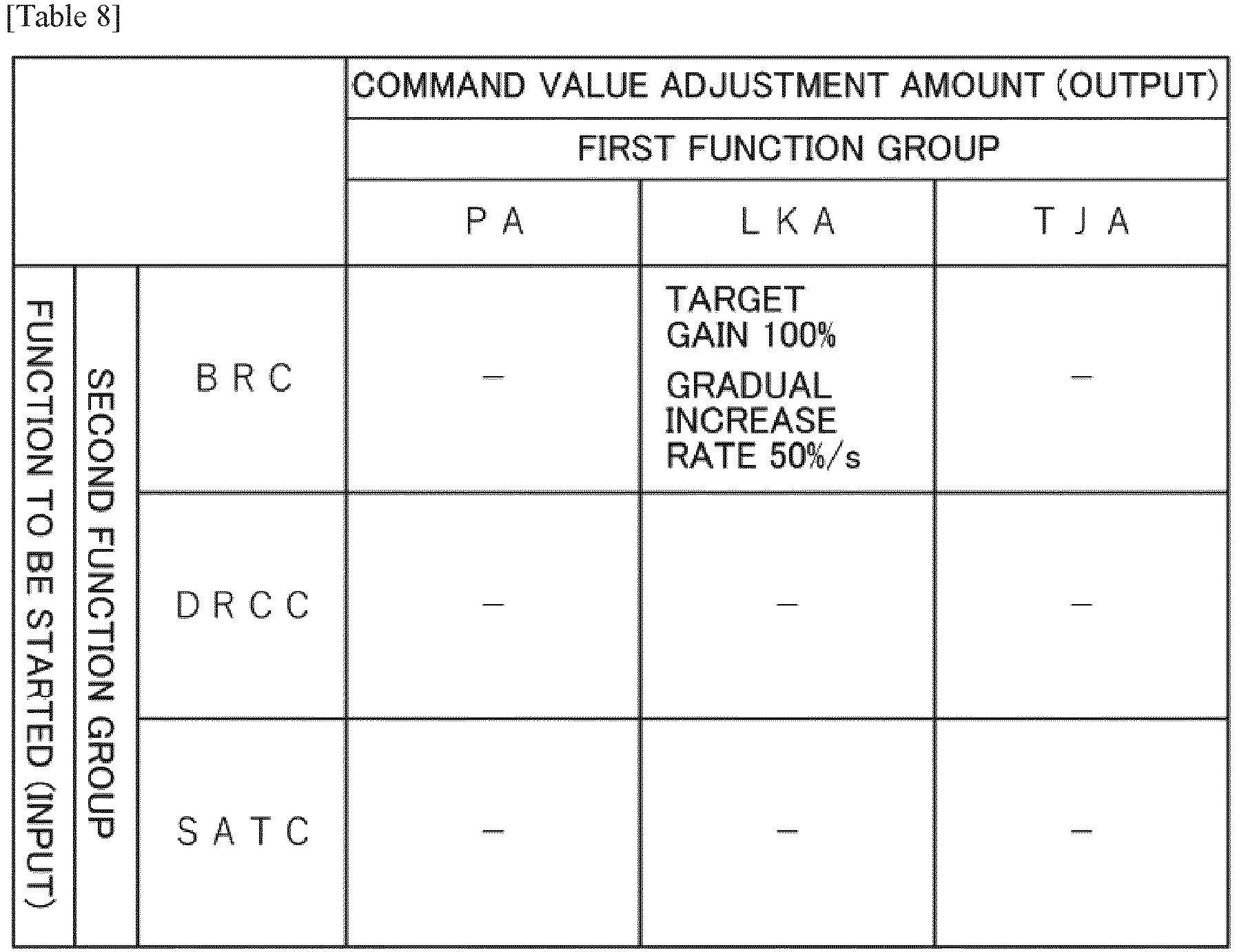
- The stop command value adjustment table has a command value adjustment amount for the driving assistance subsystem 100 (driving assistance subsystems PA, LKA, TJA) of the function belonging to the automatic driving function group (first function group), for each driving assistance subsystem 100 (driving assistance subsystems BRC, DRCC, STAC) of the function belonging to the steering feeling improving function group (second function group) to be stopped.
- For example, when the command value of the driving assistance subsystem BRC is equal to or less than the threshold value, or when the moving average of the absolute value of the command value is equal to or less than the threshold value, the command value adjusting module 113C outputs a command value adjustment amount of "gradually increasing the output gain at 50% / s to finally make the gain 100%" to the driving assistance subsystem LKA as shown in Table 8. By comparing the moving average of the absolute value of the command value with the threshold value, the momentary gradual increase can be suppressed and the steering discomfort is reduced.
- When the driving
assistance subsystem 100 of the function belonging to the steering feeling improvement function group (second function group) is stopped, the command value adjusting module 113C outputs a command value adjustment amount that restores the adjusted command value of the drivingassistance subsystem 100 of the function belonging to the automatic driving function group (first function group). - According to the power steering device 200C of the present embodiment, a plurality of driving assistance functions that can be operated at the same time can be operated in a coordinated manner. The functions belonging to the automatic driving function group (first function group) and the steering feeling improving function group (second function group) can be operated in coordination at the same time.
- The present invention can be applied to a steering device or the like having a driving assistance function classified into two or more types of functions such as a steering feeling improving function group and an automatic driving function group.
-
- 200, 200B
- Power steering device (Steering device)
- 1
- Handle
- 2
- Steering mechanism
- 20
- Steering shaft
- 29
- Torque sensor
- 3
- Steering assistance mechanism
- 30
- Electric motor
- 31
- Reduction mechanism
- 32
- Vehicle speed sensor
- 34
- Controller
- 35
- Motor drive circuit
- 100
- Driving assistance subsystem
- 101
- Start determination module
- 102
- Driving assistance module
- 103
- Command value output module
- 110, 110B
- Arbitration module
- 111
- Priority determination module
- 112
- Start-approval determination module
- 113, 113B
- Command value adjusting module
- 120
- Motor control module
- 121
- Torque control module
- 122
- Current control module
Claims (11)
- A steering device comprising:a motor configured to assist or drive a steering; anda controller configured to control the motor,wherein the controller is configured toreceive a steering request for a plirlity of assistance functions,select a driving assistance function to be operated at the same time from the driving assistance functions for which the steering request was made,calculate a command value for the motor for each of the selected driving assistance function,adjust the command value based on a combination of the selected driving assistance function, andcalculate a final command value for the motor using the adjusted command value.
- The steering device according to Claim 1, whereinthe plurality of driving assistance functions include first driving assistance functions belonging to a first function group and second driving assistance functions belonging to a second function group, andwhen selecting the driving assistance functions to be operated at the same time, the controller is configured to select one of the first driving assistance functions based on a priority from the first driving assistance functions belonging to the first function group.
- The steering device according to Claim 2, wherein
when selecting the driving assistance functions to be operated at the same time, the controller is configured to select all the second driving assistance functions for which the steering request has been made from the second driving assistance functions belonging to the second function group. - The steering device according to Claim 2 or Claim 3, wherein
the controller is configured tocalculate a first command value, which is the command value by the selected first driving assistance function,calculate a second command value, which is the command value by the selected second driving assistance function,adjust the second command value so that the first command value has priority, andcalculate the final command value using the first command value and the adjusted second command value. - The steering device according to Claim 4, wherein the controller is configured to use a moving average value of an absolute value of the first command value when adjusting the second command value.
- The steering device according to Claim 2 or Claim 3, wherein
the controller is configured tocalculate a first command value, which is the command value by the selected first driving assistance function,calculate a second command value, which is the command value by the selected second driving assistance function,adjust the first command value so that the second command value has priority, andcalculate the final command value using the second command value and the adjusted first command value. - The steering device according to Claim 6, wherein the controller uses a moving average value of an absolute value of the second command value when adjusting the first command value.
- The steering device according to any one of Claims 1 to 7, wherein the command value is at least one of a current command value for the motor, a steering torque, a vehicle speed, a steering angle, a steering angular velocity, and a steering angular acceleration.
- The steering device according to any one of Claims 2 to 7, whereinthe first driving assistance function belonging to the first function group is an automatic driving function, andthe second driving assistance function belonging to the second function group is a steering feeling improving function.
- The steering device according to Claim 9, wherein the automatic driving function includes at least one of a parking assistance function, a lane keeping assistance function, and a traffic jam driving assistance function.
- The steering device according to Claim 9, wherein the steering feeling improving function includes at least one of a drive mode switching function, a bank road driving compensation function, a driving track convergence control, and a self-alignment torque compensation.
Applications Claiming Priority (2)
| Application Number | Priority Date | Filing Date | Title |
|---|---|---|---|
| JP2020075728 | 2020-04-21 | ||
| PCT/JP2021/004590 WO2021215078A1 (en) | 2020-04-21 | 2021-02-08 | Steering device |
Publications (3)
| Publication Number | Publication Date |
|---|---|
| EP3932778A1 true EP3932778A1 (en) | 2022-01-05 |
| EP3932778A4 EP3932778A4 (en) | 2022-03-09 |
| EP3932778B1 EP3932778B1 (en) | 2023-09-06 |
Family
ID=78150229
Family Applications (1)
| Application Number | Title | Priority Date | Filing Date |
|---|---|---|---|
| EP21751739.0A Active EP3932778B1 (en) | 2020-04-21 | 2021-02-08 | Steering device |
Country Status (4)
| Country | Link |
|---|---|
| US (1) | US11465672B2 (en) |
| EP (1) | EP3932778B1 (en) |
| JP (1) | JP6954506B1 (en) |
| CN (1) | CN114080345B (en) |
Families Citing this family (1)
| Publication number | Priority date | Publication date | Assignee | Title |
|---|---|---|---|---|
| JP7619910B2 (en) * | 2021-08-26 | 2025-01-22 | トヨタ自動車株式会社 | Steering system |
Family Cites Families (28)
| Publication number | Priority date | Publication date | Assignee | Title |
|---|---|---|---|---|
| JP3738673B2 (en) * | 2000-06-29 | 2006-01-25 | トヨタ自動車株式会社 | Automatic steering device for vehicles |
| JP4613976B2 (en) * | 2008-04-07 | 2011-01-19 | トヨタ自動車株式会社 | Vehicle steering control device |
| DE102009000868B4 (en) | 2009-02-16 | 2011-12-29 | Ford Global Technologies, Llc | Device and method for controlling a steering system in a vehicle |
| CN102596690B (en) | 2009-10-30 | 2015-04-29 | 丰田自动车株式会社 | Device for controlling vehicle travel |
| EP2979956B1 (en) * | 2013-03-28 | 2018-04-25 | Toyota Jidosha Kabushiki Kaisha | Collision avoidance assistance device and collision avoidance assistance method |
| JP6036522B2 (en) * | 2013-04-26 | 2016-11-30 | 株式会社デンソー | Electric steering control device |
| EP3000693B1 (en) * | 2013-05-22 | 2018-09-05 | Nissan Motor Co., Ltd | Parking assist device, and parking assist method |
| JP6314752B2 (en) * | 2014-08-28 | 2018-04-25 | 株式会社デンソー | Electric steering control device |
| EP3254933B1 (en) * | 2015-02-04 | 2019-08-14 | NSK Ltd. | Electric power steering device |
| JP6532786B2 (en) * | 2015-08-07 | 2019-06-19 | 株式会社日立製作所 | Vehicle travel control device and speed control method |
| KR102494255B1 (en) | 2016-01-04 | 2023-02-03 | 에이치엘만도 주식회사 | Steering Arbitration Apparatus and Method of Vehicle, and Steering Arbitration System having the same |
| JP6641595B2 (en) * | 2016-02-15 | 2020-02-05 | 株式会社ジェイテクト | Vehicle alarm system |
| WO2017208652A1 (en) * | 2016-06-03 | 2017-12-07 | 日立オートモティブシステムズ株式会社 | Motor control device |
| US10513287B2 (en) * | 2016-06-06 | 2019-12-24 | Nsk Ltd. | Electric power steering apparatus |
| JP6705314B2 (en) * | 2016-07-05 | 2020-06-03 | 株式会社デンソー | Steering control device |
| JP6801593B2 (en) * | 2017-06-14 | 2020-12-16 | 株式会社デンソー | Vehicle steering support device and steering support control method |
| JP6601595B2 (en) * | 2017-06-16 | 2019-11-06 | 日本精工株式会社 | Motor control device and electric power steering device equipped with the same |
| JP6955197B2 (en) * | 2017-07-26 | 2021-10-27 | 株式会社ジェイテクト | Steering control device |
| CN111278714B (en) * | 2017-11-02 | 2022-07-05 | 株式会社捷太格特 | Steering control device |
| JP2019098964A (en) * | 2017-12-04 | 2019-06-24 | 日本精工株式会社 | Electric power steering device |
| US20190210649A1 (en) * | 2018-01-08 | 2019-07-11 | Robert Bosch Gmbh | Control Unit and a Method for Adapting a Steer-By-Wire System for an Automobile Driver |
| JP7014028B2 (en) * | 2018-04-19 | 2022-02-15 | 株式会社デンソー | Steering control device |
| CN109017974B (en) * | 2018-07-02 | 2020-12-25 | 南京航空航天大学 | Auxiliary steering system with active steering function and control method thereof |
| JP7087836B2 (en) * | 2018-08-29 | 2022-06-21 | トヨタ自動車株式会社 | Vehicle control systems, controls, managers, methods, programs, actuator systems, and vehicles |
| JP7254474B2 (en) * | 2018-10-09 | 2023-04-10 | 日立Astemo株式会社 | vehicle control system |
| JP7067405B2 (en) * | 2018-10-11 | 2022-05-16 | 株式会社デンソー | Rotation detector, steering system |
| JP7387998B2 (en) * | 2019-04-15 | 2023-11-29 | 株式会社ジェイテクト | Steering control device |
| US11407442B2 (en) * | 2019-07-31 | 2022-08-09 | Steering Solutions Ip Holding Corporation | Steer-by-wire system |
-
2021
- 2021-02-08 JP JP2021535775A patent/JP6954506B1/en active Active
- 2021-02-08 US US17/431,817 patent/US11465672B2/en active Active
- 2021-02-08 CN CN202180002511.5A patent/CN114080345B/en active Active
- 2021-02-08 EP EP21751739.0A patent/EP3932778B1/en active Active
Also Published As
| Publication number | Publication date |
|---|---|
| CN114080345A (en) | 2022-02-22 |
| US20220097755A1 (en) | 2022-03-31 |
| EP3932778B1 (en) | 2023-09-06 |
| EP3932778A4 (en) | 2022-03-09 |
| JP6954506B1 (en) | 2021-10-27 |
| US11465672B2 (en) | 2022-10-11 |
| JPWO2021215078A1 (en) | 2021-10-28 |
| CN114080345B (en) | 2023-08-08 |
Similar Documents
| Publication | Publication Date | Title |
|---|---|---|
| CN100560417C (en) | Vehicular steering control apparatus | |
| JP4492230B2 (en) | Vehicle steering control device | |
| US11066095B2 (en) | Controller for steering system and method for controlling steering system | |
| US6782968B2 (en) | Automatic steering apparatus for vehicle and control method of same | |
| EP1935753A1 (en) | Electric power steering system | |
| US6886656B2 (en) | Electric power steering apparatus | |
| EP3138758B1 (en) | Travel control device for vehicle | |
| JP5217794B2 (en) | Electric power steering device | |
| CN112124423A (en) | Steering angle calculation device and motor control device including the same | |
| JP4684698B2 (en) | Vehicle steering control device | |
| EP3287341B1 (en) | Vehicle controller | |
| KR20100074305A (en) | Steering control | |
| US7882925B2 (en) | Vehicle steering apparatus | |
| EP3932778B1 (en) | Steering device | |
| US11685429B2 (en) | Steering control device | |
| US20210122413A1 (en) | Steering control device | |
| JP2010158987A (en) | Vehicular steering control device | |
| JP4811188B2 (en) | Vehicle steering control device | |
| WO2022085536A1 (en) | Steering device | |
| US7134522B2 (en) | Reaction force control apparatus | |
| JP2007510582A (en) | Auto assist power steering system | |
| WO2021215078A1 (en) | Steering device | |
| US12037055B2 (en) | Steering control device | |
| JP4904518B2 (en) | Control device for electric power steering device | |
| JP2005289190A (en) | Electric power steering device |
Legal Events
| Date | Code | Title | Description |
|---|---|---|---|
| STAA | Information on the status of an ep patent application or granted ep patent |
Free format text: STATUS: UNKNOWN |
|
| STAA | Information on the status of an ep patent application or granted ep patent |
Free format text: STATUS: THE INTERNATIONAL PUBLICATION HAS BEEN MADE |
|
| PUAI | Public reference made under article 153(3) epc to a published international application that has entered the european phase |
Free format text: ORIGINAL CODE: 0009012 |
|
| STAA | Information on the status of an ep patent application or granted ep patent |
Free format text: STATUS: REQUEST FOR EXAMINATION WAS MADE |
|
| 17P | Request for examination filed |
Effective date: 20210817 |
|
| AK | Designated contracting states |
Kind code of ref document: A1 Designated state(s): AL AT BE BG CH CY CZ DE DK EE ES FI FR GB GR HR HU IE IS IT LI LT LU LV MC MK MT NL NO PL PT RO RS SE SI SK SM TR |
|
| STAA | Information on the status of an ep patent application or granted ep patent |
Free format text: STATUS: EXAMINATION IS IN PROGRESS |
|
| A4 | Supplementary search report drawn up and despatched |
Effective date: 20220209 |
|
| RIC1 | Information provided on ipc code assigned before grant |
Ipc: B62D 15/02 20060101ALI20220203BHEP Ipc: B62D 5/04 20060101ALI20220203BHEP Ipc: B62D 6/00 20060101AFI20220203BHEP |
|
| 17Q | First examination report despatched |
Effective date: 20220221 |
|
| GRAP | Despatch of communication of intention to grant a patent |
Free format text: ORIGINAL CODE: EPIDOSNIGR1 |
|
| STAA | Information on the status of an ep patent application or granted ep patent |
Free format text: STATUS: GRANT OF PATENT IS INTENDED |
|
| INTG | Intention to grant announced |
Effective date: 20230404 |
|
| DAV | Request for validation of the european patent (deleted) | ||
| DAX | Request for extension of the european patent (deleted) | ||
| GRAS | Grant fee paid |
Free format text: ORIGINAL CODE: EPIDOSNIGR3 |
|
| GRAA | (expected) grant |
Free format text: ORIGINAL CODE: 0009210 |
|
| STAA | Information on the status of an ep patent application or granted ep patent |
Free format text: STATUS: THE PATENT HAS BEEN GRANTED |
|
| AK | Designated contracting states |
Kind code of ref document: B1 Designated state(s): AL AT BE BG CH CY CZ DE DK EE ES FI FR GB GR HR HU IE IS IT LI LT LU LV MC MK MT NL NO PL PT RO RS SE SI SK SM TR |
|
| REG | Reference to a national code |
Ref country code: GB Ref legal event code: FG4D |
|
| RIN1 | Information on inventor provided before grant (corrected) |
Inventor name: SHIBATA, TSUTOMU |
|
| REG | Reference to a national code |
Ref country code: CH Ref legal event code: EP |
|
| REG | Reference to a national code |
Ref country code: IE Ref legal event code: FG4D |
|
| REG | Reference to a national code |
Ref country code: DE Ref legal event code: R096 Ref document number: 602021004990 Country of ref document: DE |
|
| REG | Reference to a national code |
Ref country code: LT Ref legal event code: MG9D |
|
| REG | Reference to a national code |
Ref country code: NL Ref legal event code: MP Effective date: 20230906 |
|
| PG25 | Lapsed in a contracting state [announced via postgrant information from national office to epo] |
Ref country code: GR Free format text: LAPSE BECAUSE OF FAILURE TO SUBMIT A TRANSLATION OF THE DESCRIPTION OR TO PAY THE FEE WITHIN THE PRESCRIBED TIME-LIMIT Effective date: 20231207 |
|
| PG25 | Lapsed in a contracting state [announced via postgrant information from national office to epo] |
Ref country code: SE Free format text: LAPSE BECAUSE OF FAILURE TO SUBMIT A TRANSLATION OF THE DESCRIPTION OR TO PAY THE FEE WITHIN THE PRESCRIBED TIME-LIMIT Effective date: 20230906 Ref country code: RS Free format text: LAPSE BECAUSE OF FAILURE TO SUBMIT A TRANSLATION OF THE DESCRIPTION OR TO PAY THE FEE WITHIN THE PRESCRIBED TIME-LIMIT Effective date: 20230906 Ref country code: NO Free format text: LAPSE BECAUSE OF FAILURE TO SUBMIT A TRANSLATION OF THE DESCRIPTION OR TO PAY THE FEE WITHIN THE PRESCRIBED TIME-LIMIT Effective date: 20231206 Ref country code: LV Free format text: LAPSE BECAUSE OF FAILURE TO SUBMIT A TRANSLATION OF THE DESCRIPTION OR TO PAY THE FEE WITHIN THE PRESCRIBED TIME-LIMIT Effective date: 20230906 Ref country code: LT Free format text: LAPSE BECAUSE OF FAILURE TO SUBMIT A TRANSLATION OF THE DESCRIPTION OR TO PAY THE FEE WITHIN THE PRESCRIBED TIME-LIMIT Effective date: 20230906 Ref country code: HR Free format text: LAPSE BECAUSE OF FAILURE TO SUBMIT A TRANSLATION OF THE DESCRIPTION OR TO PAY THE FEE WITHIN THE PRESCRIBED TIME-LIMIT Effective date: 20230906 Ref country code: GR Free format text: LAPSE BECAUSE OF FAILURE TO SUBMIT A TRANSLATION OF THE DESCRIPTION OR TO PAY THE FEE WITHIN THE PRESCRIBED TIME-LIMIT Effective date: 20231207 Ref country code: FI Free format text: LAPSE BECAUSE OF FAILURE TO SUBMIT A TRANSLATION OF THE DESCRIPTION OR TO PAY THE FEE WITHIN THE PRESCRIBED TIME-LIMIT Effective date: 20230906 |
|
| REG | Reference to a national code |
Ref country code: AT Ref legal event code: MK05 Ref document number: 1608192 Country of ref document: AT Kind code of ref document: T Effective date: 20230906 |
|
| PG25 | Lapsed in a contracting state [announced via postgrant information from national office to epo] |
Ref country code: NL Free format text: LAPSE BECAUSE OF FAILURE TO SUBMIT A TRANSLATION OF THE DESCRIPTION OR TO PAY THE FEE WITHIN THE PRESCRIBED TIME-LIMIT Effective date: 20230906 |
|
| PG25 | Lapsed in a contracting state [announced via postgrant information from national office to epo] |
Ref country code: IS Free format text: LAPSE BECAUSE OF FAILURE TO SUBMIT A TRANSLATION OF THE DESCRIPTION OR TO PAY THE FEE WITHIN THE PRESCRIBED TIME-LIMIT Effective date: 20240106 |
|
| PG25 | Lapsed in a contracting state [announced via postgrant information from national office to epo] |
Ref country code: AT Free format text: LAPSE BECAUSE OF FAILURE TO SUBMIT A TRANSLATION OF THE DESCRIPTION OR TO PAY THE FEE WITHIN THE PRESCRIBED TIME-LIMIT Effective date: 20230906 |
|
| PG25 | Lapsed in a contracting state [announced via postgrant information from national office to epo] |
Ref country code: ES Free format text: LAPSE BECAUSE OF FAILURE TO SUBMIT A TRANSLATION OF THE DESCRIPTION OR TO PAY THE FEE WITHIN THE PRESCRIBED TIME-LIMIT Effective date: 20230906 |
|
| PG25 | Lapsed in a contracting state [announced via postgrant information from national office to epo] |
Ref country code: SM Free format text: LAPSE BECAUSE OF FAILURE TO SUBMIT A TRANSLATION OF THE DESCRIPTION OR TO PAY THE FEE WITHIN THE PRESCRIBED TIME-LIMIT Effective date: 20230906 Ref country code: RO Free format text: LAPSE BECAUSE OF FAILURE TO SUBMIT A TRANSLATION OF THE DESCRIPTION OR TO PAY THE FEE WITHIN THE PRESCRIBED TIME-LIMIT Effective date: 20230906 Ref country code: IS Free format text: LAPSE BECAUSE OF FAILURE TO SUBMIT A TRANSLATION OF THE DESCRIPTION OR TO PAY THE FEE WITHIN THE PRESCRIBED TIME-LIMIT Effective date: 20240106 Ref country code: ES Free format text: LAPSE BECAUSE OF FAILURE TO SUBMIT A TRANSLATION OF THE DESCRIPTION OR TO PAY THE FEE WITHIN THE PRESCRIBED TIME-LIMIT Effective date: 20230906 Ref country code: EE Free format text: LAPSE BECAUSE OF FAILURE TO SUBMIT A TRANSLATION OF THE DESCRIPTION OR TO PAY THE FEE WITHIN THE PRESCRIBED TIME-LIMIT Effective date: 20230906 Ref country code: CZ Free format text: LAPSE BECAUSE OF FAILURE TO SUBMIT A TRANSLATION OF THE DESCRIPTION OR TO PAY THE FEE WITHIN THE PRESCRIBED TIME-LIMIT Effective date: 20230906 Ref country code: AT Free format text: LAPSE BECAUSE OF FAILURE TO SUBMIT A TRANSLATION OF THE DESCRIPTION OR TO PAY THE FEE WITHIN THE PRESCRIBED TIME-LIMIT Effective date: 20230906 Ref country code: SK Free format text: LAPSE BECAUSE OF FAILURE TO SUBMIT A TRANSLATION OF THE DESCRIPTION OR TO PAY THE FEE WITHIN THE PRESCRIBED TIME-LIMIT Effective date: 20230906 Ref country code: PT Free format text: LAPSE BECAUSE OF FAILURE TO SUBMIT A TRANSLATION OF THE DESCRIPTION OR TO PAY THE FEE WITHIN THE PRESCRIBED TIME-LIMIT Effective date: 20240108 |
|
| PG25 | Lapsed in a contracting state [announced via postgrant information from national office to epo] |
Ref country code: PL Free format text: LAPSE BECAUSE OF FAILURE TO SUBMIT A TRANSLATION OF THE DESCRIPTION OR TO PAY THE FEE WITHIN THE PRESCRIBED TIME-LIMIT Effective date: 20230906 Ref country code: IT Free format text: LAPSE BECAUSE OF FAILURE TO SUBMIT A TRANSLATION OF THE DESCRIPTION OR TO PAY THE FEE WITHIN THE PRESCRIBED TIME-LIMIT Effective date: 20230906 |
|
| REG | Reference to a national code |
Ref country code: DE Ref legal event code: R097 Ref document number: 602021004990 Country of ref document: DE |
|
| PG25 | Lapsed in a contracting state [announced via postgrant information from national office to epo] |
Ref country code: DK Free format text: LAPSE BECAUSE OF FAILURE TO SUBMIT A TRANSLATION OF THE DESCRIPTION OR TO PAY THE FEE WITHIN THE PRESCRIBED TIME-LIMIT Effective date: 20230906 |
|
| PLBE | No opposition filed within time limit |
Free format text: ORIGINAL CODE: 0009261 |
|
| STAA | Information on the status of an ep patent application or granted ep patent |
Free format text: STATUS: NO OPPOSITION FILED WITHIN TIME LIMIT |
|
| PG25 | Lapsed in a contracting state [announced via postgrant information from national office to epo] |
Ref country code: DK Free format text: LAPSE BECAUSE OF FAILURE TO SUBMIT A TRANSLATION OF THE DESCRIPTION OR TO PAY THE FEE WITHIN THE PRESCRIBED TIME-LIMIT Effective date: 20230906 Ref country code: SI Free format text: LAPSE BECAUSE OF FAILURE TO SUBMIT A TRANSLATION OF THE DESCRIPTION OR TO PAY THE FEE WITHIN THE PRESCRIBED TIME-LIMIT Effective date: 20230906 |
|
| 26N | No opposition filed |
Effective date: 20240607 |
|
| PG25 | Lapsed in a contracting state [announced via postgrant information from national office to epo] |
Ref country code: MC Free format text: LAPSE BECAUSE OF FAILURE TO SUBMIT A TRANSLATION OF THE DESCRIPTION OR TO PAY THE FEE WITHIN THE PRESCRIBED TIME-LIMIT Effective date: 20230906 |
|
| REG | Reference to a national code |
Ref country code: CH Ref legal event code: PL |
|
| PG25 | Lapsed in a contracting state [announced via postgrant information from national office to epo] |
Ref country code: LU Free format text: LAPSE BECAUSE OF NON-PAYMENT OF DUE FEES Effective date: 20240208 |
|
| PG25 | Lapsed in a contracting state [announced via postgrant information from national office to epo] |
Ref country code: CH Free format text: LAPSE BECAUSE OF NON-PAYMENT OF DUE FEES Effective date: 20240229 |
|
| PG25 | Lapsed in a contracting state [announced via postgrant information from national office to epo] |
Ref country code: LU Free format text: LAPSE BECAUSE OF NON-PAYMENT OF DUE FEES Effective date: 20240208 Ref country code: CH Free format text: LAPSE BECAUSE OF NON-PAYMENT OF DUE FEES Effective date: 20240229 |
|
| PG25 | Lapsed in a contracting state [announced via postgrant information from national office to epo] |
Ref country code: BG Free format text: LAPSE BECAUSE OF FAILURE TO SUBMIT A TRANSLATION OF THE DESCRIPTION OR TO PAY THE FEE WITHIN THE PRESCRIBED TIME-LIMIT Effective date: 20230906 |
|
| PG25 | Lapsed in a contracting state [announced via postgrant information from national office to epo] |
Ref country code: BG Free format text: LAPSE BECAUSE OF FAILURE TO SUBMIT A TRANSLATION OF THE DESCRIPTION OR TO PAY THE FEE WITHIN THE PRESCRIBED TIME-LIMIT Effective date: 20230906 |
|
| REG | Reference to a national code |
Ref country code: BE Ref legal event code: MM Effective date: 20240229 |
|
| PG25 | Lapsed in a contracting state [announced via postgrant information from national office to epo] |
Ref country code: BE Free format text: LAPSE BECAUSE OF NON-PAYMENT OF DUE FEES Effective date: 20240229 |
|
| PG25 | Lapsed in a contracting state [announced via postgrant information from national office to epo] |
Ref country code: IE Free format text: LAPSE BECAUSE OF NON-PAYMENT OF DUE FEES Effective date: 20240208 |
|
| PG25 | Lapsed in a contracting state [announced via postgrant information from national office to epo] |
Ref country code: IE Free format text: LAPSE BECAUSE OF NON-PAYMENT OF DUE FEES Effective date: 20240208 Ref country code: BE Free format text: LAPSE BECAUSE OF NON-PAYMENT OF DUE FEES Effective date: 20240229 |
|
| PG25 | Lapsed in a contracting state [announced via postgrant information from national office to epo] |
Ref country code: CY Free format text: LAPSE BECAUSE OF FAILURE TO SUBMIT A TRANSLATION OF THE DESCRIPTION OR TO PAY THE FEE WITHIN THE PRESCRIBED TIME-LIMIT; INVALID AB INITIO Effective date: 20210208 |
|
| PG25 | Lapsed in a contracting state [announced via postgrant information from national office to epo] |
Ref country code: HU Free format text: LAPSE BECAUSE OF FAILURE TO SUBMIT A TRANSLATION OF THE DESCRIPTION OR TO PAY THE FEE WITHIN THE PRESCRIBED TIME-LIMIT; INVALID AB INITIO Effective date: 20210208 |
|
| GBPC | Gb: european patent ceased through non-payment of renewal fee |
Effective date: 20250208 |
|
| PG25 | Lapsed in a contracting state [announced via postgrant information from national office to epo] |
Ref country code: TR Free format text: LAPSE BECAUSE OF FAILURE TO SUBMIT A TRANSLATION OF THE DESCRIPTION OR TO PAY THE FEE WITHIN THE PRESCRIBED TIME-LIMIT Effective date: 20230906 |
|
| PG25 | Lapsed in a contracting state [announced via postgrant information from national office to epo] |
Ref country code: GB Free format text: LAPSE BECAUSE OF NON-PAYMENT OF DUE FEES Effective date: 20250208 |
|
| PGFP | Annual fee paid to national office [announced via postgrant information from national office to epo] |
Ref country code: FR Payment date: 20251231 Year of fee payment: 6 |
|
| PGFP | Annual fee paid to national office [announced via postgrant information from national office to epo] |
Ref country code: DE Payment date: 20251230 Year of fee payment: 6 |