EP3932624A1 - Gravity compensation assembly, and robot waist structure including same - Google Patents
Gravity compensation assembly, and robot waist structure including same Download PDFInfo
- Publication number
- EP3932624A1 EP3932624A1 EP20763452.8A EP20763452A EP3932624A1 EP 3932624 A1 EP3932624 A1 EP 3932624A1 EP 20763452 A EP20763452 A EP 20763452A EP 3932624 A1 EP3932624 A1 EP 3932624A1
- Authority
- EP
- European Patent Office
- Prior art keywords
- rotation portion
- assembly
- rotation
- auxiliary
- link
- Prior art date
- Legal status (The legal status is an assumption and is not a legal conclusion. Google has not performed a legal analysis and makes no representation as to the accuracy of the status listed.)
- Pending
Links
Images






Classifications
-
- B—PERFORMING OPERATIONS; TRANSPORTING
- B25—HAND TOOLS; PORTABLE POWER-DRIVEN TOOLS; MANIPULATORS
- B25J—MANIPULATORS; CHAMBERS PROVIDED WITH MANIPULATION DEVICES
- B25J19/00—Accessories fitted to manipulators, e.g. for monitoring, for viewing; Safety devices combined with or specially adapted for use in connection with manipulators
- B25J19/0008—Balancing devices
- B25J19/0016—Balancing devices using springs
-
- B—PERFORMING OPERATIONS; TRANSPORTING
- B25—HAND TOOLS; PORTABLE POWER-DRIVEN TOOLS; MANIPULATORS
- B25J—MANIPULATORS; CHAMBERS PROVIDED WITH MANIPULATION DEVICES
- B25J17/00—Joints
-
- B—PERFORMING OPERATIONS; TRANSPORTING
- B25—HAND TOOLS; PORTABLE POWER-DRIVEN TOOLS; MANIPULATORS
- B25J—MANIPULATORS; CHAMBERS PROVIDED WITH MANIPULATION DEVICES
- B25J19/00—Accessories fitted to manipulators, e.g. for monitoring, for viewing; Safety devices combined with or specially adapted for use in connection with manipulators
- B25J19/0008—Balancing devices
- B25J19/002—Balancing devices using counterweights
Definitions
- the present disclosure relates to gravity compensation assemblies and/or waist structures of a robot including the same, and more particularly, to gravity compensation assemblies capable of performing gravity compensation by an elastic force providing assembly, and/or waist structures of a robot including the gravity compensation assembly.
- Such humanoid robots essentially require a gravity compensation structure for compensating for a shift in the center of gravity according to movement of an upper body, in a waist structure connecting the upper body and a lower body.
- a gravity compensation structure currently applied to a waist structure of a robot has a complicated mechanism, and thus but it is not only difficult to implement the gravity compensation structure, but also difficult to secure multi-degree of freedom, manufacturing costs are high, and it is difficult to quickly deal with a malfunction.
- the present disclosure has been devised to solve the problems of the related art, and the present disclosure provides gravity compensation structures having a high degree of freedom and relatively simple structures.
- the present disclosure provides methods of applying such gravity compensation structures to waist structures of a robot to reproduce the waist movement of a human with improved precision.
- a gravity compensation assembly includes a main frame assembly having one side connected to a weight body that is to be supported, and the other side where an inner rotation portion and an outer rotation portion spaced apart from each other and having rotation axes in an x-axis direction are coupled, an auxiliary frame assembly having one side rotatably connected to the inner rotation portion of the main frame assembly, and the other side where an auxiliary rotation portion having a rotation axis in the x-axis direction is coupled, and an elastic force providing assembly having one side rotatably connected to the outer rotation portion of the main frame assembly, and the other side coupled to the auxiliary rotation portion of the auxiliary frame assembly, the elastic force providing assembly configured to perform load compensation by an elastic force when a center of gravity changes as a relative angle of the main frame assembly and the auxiliary frame assembly changes.
- the auxiliary frame assembly may include a fixed frame and a roll rotation portion connected to the inner rotation portion and configured to rotate based on a rotation axis in a y-axis direction from one side of the fixed frame.
- the auxiliary rotation portion may be configured to rotate based on the rotation axis in the y-axis direction from the other side of the fixed frame.
- the main frame assembly may include an auxiliary roll rotation portion configured to rotate the outer rotation portion based on the rotation axis in the y-axis direction, and the auxiliary roll rotation portion may be configured to rotate in connection with rotation of the roll rotation portion and rotation of the auxiliary rotation portion.
- the elastic force providing assembly may include a center bar having one side rotatably connected to the outer rotation portion of the main frame assembly, and elongated in a length direction, a fixing member provided on the other side of the center bar, and an elastic member having one side coupled to the auxiliary rotation portion and the other side coupled to the fixing member, the elastic member configured to perform load compensation by an elastic force by being compressed with movement of the center bar according to movement of the main frame assembly.
- the elastic force providing assembly may further include an elastic force adjusting part configured to adjust an elastic force of the elastic member by changing a distance between the fixing member and the elastic member.
- the main frame assembly may include a center of gravity changing part configured to change the center of gravity by adjusting a horizontal position of the outer rotation portion.
- the main frame assembly may include a distance changing part configured to change a distance between the inner rotation portion and the outer rotation portion.
- the main frame assembly may be configured to be rotatably connected to the weight body based on the rotation axis in the x-axis direction.
- the gravity compensation assembly may further include a link assembly spaced apart from and in parallel with the main frame assembly, the link assembly comprising a link frame having one side where a first link rotation portion rotatably connected to the weight body based on the rotation axis in the x-axis direction is coupled, and the other side where a second link rotation portion rotatably connected to the auxiliary frame assembly based on the rotation axis in the x-axis direction is coupled, the link assembly coupled to perform compensation such that, when the center of gravity of the weight body is changed, a constant center of gravity is achieved according to rotation of the first link rotation portion and second link rotation portion.
- the gravity compensation assembly further includes a pair of link frames including the link frame and spaced apart from each other in a left-and-right direction.
- Each of the pair of link frames may be curved inward.
- the gravity compensation assembly further includes a third link rotation portion rotatably connected to the weight body based on a rotation axis in a y-axis direction and being on the one side of the link frame, and a fourth link rotation portion rotatably connected to the auxiliary frame assembly based on the rotation axis in the y-axis direction and being on the other side of the link frame.
- the auxiliary frame assembly may include a fixed frame to which the second link rotation portion of the link frame is rotatably connected and a roll rotation portion connected to the inner rotation portion and configured to rotate based on a rotation axis in a y-axis direction from one side of the fixed frame.
- the auxiliary rotation portion may be configured rotate based on the rotation axis in the y-axis direction from the other side of the fixed frame.
- the main frame assembly may include an auxiliary roll rotation portion configured to rotate the outer rotation portion based on the rotation axis in the y-axis direction, and the auxiliary roll rotation portion may be configured to rotate in connection with rotation of the roll rotation portion and rotation of the auxiliary rotation portion.
- the inner rotation portion and the auxiliary rotation portion each may include a universal joint, and the outer rotation portion may include a ball joint.
- the main frame assembly may include a main frame that is a center support structure.
- the main frame assembly may further include an auxiliary roll rotation portion configured to rotate the outer rotation portion based on a rotation axis in a y-axis direction, and a connecting portion connecting the main frame and the auxiliary roll rotation portion to each other.
- a waist structure of a robot includes the aforementioned gravity compensation assembly.
- a gravity compensation assembly and a waist structure of a robot including the same of the present disclosure for resolving the above problems may have following effects.
- a degree of freedom is high because not only pitch rotation, but also roll rotation of a joint can be implemented, and thus an operation similar to waist movement of a human can be performed with improved precision.
- a structure is relatively simple and can be relatively easily implemented, and thus a quicker response may be possible even during a malfunction.
- FIG. 1 is a diagram showing a structure of a gravity compensation assembly according to an example embodiment of the present disclosure
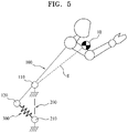
- FIGS. 2 through 5 are diagrams schematically showing a principle of the gravity compensation assembly, according to an example embodiment of the present disclosure.
- the gravity compensation assembly largely includes a main frame assembly 100, an auxiliary frame assembly 200, and an elastic force providing assembly 300.
- one side is connected to a weight body 10 to be supported, and an inner rotation portion 110 and an outer rotation portion 120 spaced apart from each other and having rotation axes in an x-axis direction are provided on the other side.
- the auxiliary frame assembly 200 has a form in which one side is rotatably connected to the inner rotation portion 110 of the main frame assembly 100, and an auxiliary rotation portion 210 having a rotation axis in the x-axis direction is formed or provided on the other side.
- the auxiliary frame assembly 200 is realized in a form in which a plurality of components are connected to each other, but may be shown in a schematic form as shown in FIGS. 2 through 5 .
- one side is rotatably connected to the outer rotation portion 120 of the main frame assembly 100, and the other side is coupled or fixed to the auxiliary rotation portion 210 of the auxiliary frame assembly 200.
- the elastic force providing assembly 300 has one side rotatably connected to the outer rotation portion 120 of the main frame assembly 100 based on the x-axis direction and the other side fixed to the auxiliary rotation portion 210 of the auxiliary frame assembly 200, and performs load compensation by an elastic force when the center of gravity changes as a relative angle between the main frame assembly 100 and the auxiliary frame assembly 200 changes.
- the gravity compensation assembly has a form in which a pair of any one of the inner rotation portion 110, the outer rotation portion 120, and the auxiliary rotation portion 210 are connected to each other as shown in FIGS. 1 and 2 , and the main frame assembly 100 extends further upward than the inner rotation portion 110 to support the weight body 10.
- a universal joint type is applied to the inner rotation portion 110 and the auxiliary rotation portion 210, and a ball joint type for realizing two-degree-of-freedom described below is applied to the outer rotation portion 120, but it is obvious that the two-degree-of-freedom to be realized in the present disclosure may be configured even when the universal joint type is applied to the inner rotation portion 110 and the outer rotation portion 120, and the ball joint type is applied to the auxiliary rotation portion 210.
- the inner rotation portion 110 and the auxiliary rotation portion 210 each include a universal joint
- the outer rotation portion 120 includes a ball joint
- FIGS. 3 and 4 schematically shows such a gravity compensation assembly being applied to a waist joint of a robot, wherein the weight body 10 being supported is an upper body structure of the robot.
- the inner rotation portion 110, the outer rotation portion 120, and the auxiliary rotation portion 210 are balanced by being positioned on a straight line with the center of gravity g.
- the main frame assembly 100 when the waist joint of the robot is pitch-rotated, the main frame assembly 100 is tilted and thus the center of gravity g of the weight body 10 is changed, and accordingly, the main frame assembly 100, the auxiliary frame assembly 200, and the elastic force providing assembly 300 are relatively rotated to form a triangular shape, based on the inner rotation portion 110, the outer rotation portion 120, and the auxiliary rotation portion 210.
- the elastic force providing assembly 300 is elastically deformed, and the changed center of gravity g of the weight body 10 is compensated for by a consequent restoring force, thereby achieving balance. Also, when a pitch rotation angle is increased or decreased, the deformation of the elastic force providing assembly 300 is also changed proportionally, and thus the center of gravity g of the weight body 10 may be compensated for in a similar manner to achieve balance.
- the auxiliary frame assembly 200 may further include a roll rotation portion configured to rotate based on a rotation axis in a y-axis direction, and the auxiliary rotation portion 210 may also be configured to rotate based on a rotation axis in the y-axis direction, such that the weight body 10 is not only to pitch-rotated, but also roll-rotated.
- the elastic force providing assembly 300 is elastically deformed, and thus the center of gravity g of the weight body 10 may be compensated for. This will be described in detail below.
- the center of gravity g of the upper body structure of the robot (e.g., the weight body 10) may change according to movement of an arm or the like.
- the gravity compensation assembly of the present disclosure may further include a structure for compensating for the change in the center of gravity g according to the movement of the weight body 10.
- FIG. 6 is a diagram of a structure for compensating for a shift of the center of gravity, in the gravity compensation assembly according to an example embodiment of the present disclosure.
- the gravity compensation assembly may further include a link assembly 400 spaced apart from and in parallel with the main frame assembly 100, and having one side where a first link rotation portion 410 rotatably connected to the weight body 10 based on a rotation axis in the x-axis direction is formed (e.g., provided, coupled, or attached) and the other side where a second link rotation portion 420 rotatably connected based on a rotation axis in the x-axis direction is formed (e.g., provided, coupled, or attached), to perform compensation such that, when the center of gravity of the weight body 10 is changed, the constant center of gravity is achieved according to rotation of the first link rotation portion 410 and second link rotation portion 420.
- a link assembly 400 spaced apart from and in parallel with the main frame assembly 100, and having one side where a first link rotation portion 410 rotatably connected to the weight body 10 based on a rotation axis in the x-axis direction is formed (e.g., provided, coupled, or attached) and the
- the main frame assembly 100 further includes an auxiliary link rotation portion 130 rotatably connected to the weight body 10 based on a rotation axis in the x-axis direction.
- the link assembly 400 supports the weight body 10 together with the main frame assembly 100, and the first link rotation portion 410 and second link rotation portion 420 form vertices of a parallelogram together with the inner rotation portion 110 and auxiliary link rotation portion 130, thereby performing compensation for a change in the center of gravity of the weight body 10 caused by various reasons.
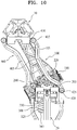
- FIGS. 7 and 8 are diagrams of a structure of the waist structure of the robot, according to an example embodiment of the present disclosure.
- the gravity compensation assembly applied as the waist structure of the robot is positioned between the weight body 10 that is the upper body structure of the robot positioned at an upper portion, and a base 20 that is a lower body structure of robot positioned at a lower portion.
- the waist structure of the robot includes the main frame assembly 100, the auxiliary frame assembly 200, the elastic force providing assembly 300, and the link assembly 400 as described above.
- the main frame assembly 100 includes a main frame 105 that is a center support structure, and the inner rotation portion 110 and the outer rotation portion 120 that are spaced apart from each other at the main frame 105.
- the auxiliary frame assembly 200 includes a fixed frame 205, a roll rotation portion 220 connected to the inner rotation portion 110 of the main frame assembly 100 and configured to rotate based on a rotation axis in the y-axis direction from one side of the fixed frame 205, and the auxiliary rotation portion 210 configured to rotate based on a rotation axis in the y-axis direction from the other side of the fixed frame 205 and having a rotation axis in the x-axis direction with respect to the elastic force providing assembly 300.
- the main frame assembly 100 may further include an auxiliary roll rotation portion 140 connected to the main frame 105 such that the outer rotation portion 120 rotates based on a rotation axis in the y-axis direction.
- the auxiliary roll rotation portion may be configured to rotate the outer rotation portion 120 based on a rotation axis in the y-axis direction.
- the auxiliary roll rotation portion 140 is formed or configured to rotate in connection with rotation of the roll rotation portion 220 and rotation of the auxiliary rotation portion 210.
- the main frame assembly 100 may perform pitch rotation as shown in FIG. 9 , according to rotation of the inner rotation portion 110 and outer rotation portion 120 based on the rotation axis in the x-axis direction, and rotation of the auxiliary rotation portion 210 based on the rotation axis in the x-axis direction.
- the main frame assembly 100 may perform roll rotation as shown in FIGS. 10 and 11 , according to rotation of the auxiliary rotation portion 210 and rotation of the roll rotation portion 220 based on the rotation axis in the y-axis direction, and associated rotation of the auxiliary roll rotation portion 140 based on the rotation axis in the y-axis direction.
- the gravity compensation assembly of the present disclosure is able to compensate for shift of the center of gravity while having a multi-degree of freedom, the gravity compensation assembly may realize movement to the waist of a human with improved precision.
- the elastic force providing assembly 300 includes a center bar 310 having one side rotatably connected to the outer rotation portion 120 of the main frame assembly 100, and elongated in a length direction, a fixing member 320 provided on the other side of the center bar 310, and an elastic member 330 having one side rotatably fixed by or rotatably coupled to the auxiliary rotation portion 210 based on a rotation axis in the x-axis direction and the other side fixed by or coupled to the fixing member 320 to perform load compensation by an elastic force by being compressed with movement of the center bar 310 according to movement of the main frame assembly 100.
- the center bar 310 linearly moves during the pitch rotation shown in FIG. 9 and the roll rotation shown in FIGS. 10 and 11 , and accordingly, a distance between the fixing member 320 and the auxiliary rotation portion 210 is drawn near, and thus the elastic member 330 may perform the load compensation by being compressed.
- the link assembly 400 includes a pair of link frames 405 spaced apart from each other in a left-and-right direction.
- the link frame 405 is spaced apart from and in parallel with the main frame 105 of the main frame assembly 100, and has one side where the first link rotation portion 410 rotatably connected to the weight body 10 based on the rotation axis in the x-axis direction is formed (e.g., provided, coupled, or attached) and the other side where the second link rotation portion 420 rotatably connected to the auxiliary frame assembly 200 based on the rotation axis in the x-axis direction is formed (e.g., provided, coupled, or attached).
- the second link rotation portion of the link frame 420 may be rotatably connected to the fixed frame 205.
- the first link rotation portion 410 and second link rotation portion 420 rotate together with the auxiliary link rotation portion 130 and the inner rotation portion 110 of the main frame 105 such that the weight body 10 maintains balance, and even when the center of gravity of the weight body 10 is changed.
- full gravity compensation may be possible.
- a third link rotation portion 415 rotatably connected to the weight body 10 based on a rotation axis in the y-axis direction is further formed (e.g., provided, coupled, or attached) at one side of the link frame 405, and a fourth link rotation portion 425 rotatably connected to the auxiliary frame assembly 200 based on a rotation axis in the y-axis direction may be further formed (e.g., provided, coupled, or attached) at the other side of the link frame 405.
- the third link rotation portion 415 and the fourth link rotation portion 425 may enable the weight body 10 to maintain the balance even during the roll rotation by rotating the link frame 405 in response to the roll rotation of the main frame 105.
- the pair of link frames 405 are formed (e.g., provided) such that a distance therebetween is drawn near as the one side and the other side are curved inward, to reduce interference with various instruments that may be added to the weight body 10.
- each of the pair of link frames 405 is curved inward.
- the full gravity compensation may be performed even during the shift of the center of gravity of the weight body 10 connected to the upper portion, and because not only the pitch rotation, but also the roll rotation of the waist joint are realized, the waist structure of the robot has a relatively high degree of freedom, and thus an operation similar to waist movement of a human may be performed with improved precision.
- FIG. 12 is a diagram showing a variable structure of the center of gravity and a distance variable structure between rotation axes, in the waist structure of the robot, according to an example embodiment of the present disclosure.
- the main frame assembly 100 may further include a center of gravity changing part 107 and a distance changing part 108.
- the main frame assembly 100 includes a connecting portion 106 connecting the main frame 105 and the auxiliary roll rotation portion 140 to each other, and the connecting portion 106 and the main frame 105 are connected to each other by the center of gravity changing part 107.
- the center of gravity changing part 107 adjusts a horizontal position of the connecting portion 106 according to a screw adjustment method.
- a horizontal position of the outer rotation portion 120 connected to the auxiliary roll rotation portion 140 is also adjusted, and thus the center of gravity of the entire structure may be changed.
- Such a center of gravity changing part 107 may compensate for the center of gravity of the entire structure when the center of gravity is misaligned from a desired state.
- the connecting portion 106 and the auxiliary roll rotation portion 140 are connected by the distance changing part 108.
- the distance changing part 108 adjusts a vertical position of the connecting portion 106 according to a screw adjustment method.
- a vertical position of the outer rotation portion 120 connected to the auxiliary roll rotation portion 140 is also adjusted, and thus the distance between the inner rotation portion 110 and the outer rotation portion 120 may be changed.
- Such a distance changing part 108 may adjust weight balance by changing the distance between the inner rotation portion 110 and the outer rotation portion 120 according to factors, such as a weight of the weight body 10, a distance between the weight body 10 and the outer rotation portion 120, and the like.
- FIG. 13 is a diagram showing an elastic variable structure of the elastic force providing assembly 300 in the waist structure of the robot, according to an example embodiment of the present disclosure.
- the elastic force providing assembly 300 may further include an elastic force adjusting part 340.
- the elastic force adjusting part 340 may change a distance between the fixing member 320 and the elastic member 330 according to a screw adjustment method.
- the elastic force adjusting part 340 may change a distance between the fixing member 320 and the auxiliary rotation portion 210 according to a screw adjustment method. This is to adjust a degree of compression of the elastic member 330 to adjust the elastic force of the elastic member 330.
- the weight balance may be adjusted by adjusting the elastic force of the elastic member 330 according to the factors, such as the weight of the weight body 10, the distance between the weight body 10 and the outer rotation portion 120, and the like.
Landscapes
- Engineering & Computer Science (AREA)
- Robotics (AREA)
- Mechanical Engineering (AREA)
- Manipulator (AREA)
- Toys (AREA)
Abstract
Description
- The present disclosure relates to gravity compensation assemblies and/or waist structures of a robot including the same, and more particularly, to gravity compensation assemblies capable of performing gravity compensation by an elastic force providing assembly, and/or waist structures of a robot including the gravity compensation assembly.
- Since Unimate, which is the first industrial robot, was used for automobile assembly in 1962, robotics has become an essential technology in the fields of production, service, medical treatment, exploration, military, and aerospace, owing to the rapid technology development and the spread of application fields.
- Purposes of conventional robots were to precisely perform simple repetitive operations at a high speed, but recently, various types and various levels of robots have been developed, such as robots for sharing activity spaces with humans via remote connection, surgery robots for facilitating various types of surgery, such as laparoscopic surgery, and industrial robots enabling safe physical contacts with humans.
- In particular, recently, there is also a focus on the development of humanoid robots very similar to humans, and accordingly, there have been efforts to mechanically reproduce body structures including joints of the humans.
- Such humanoid robots essentially require a gravity compensation structure for compensating for a shift in the center of gravity according to movement of an upper body, in a waist structure connecting the upper body and a lower body.
- However, a gravity compensation structure currently applied to a waist structure of a robot has a complicated mechanism, and thus but it is not only difficult to implement the gravity compensation structure, but also difficult to secure multi-degree of freedom, manufacturing costs are high, and it is difficult to quickly deal with a malfunction.
- Accordingly, a method for resolving such problems is required.
- The present disclosure has been devised to solve the problems of the related art, and the present disclosure provides gravity compensation structures having a high degree of freedom and relatively simple structures.
- Also, the present disclosure provides methods of applying such gravity compensation structures to waist structures of a robot to reproduce the waist movement of a human with improved precision.
- The problems of the present disclosure are not limited to those mentioned above, and other problems that are not mentioned may be clearly understood by one of ordinary skill in the art from the following description.
- According to an example embodiment of the present disclosure, a gravity compensation assembly includes a main frame assembly having one side connected to a weight body that is to be supported, and the other side where an inner rotation portion and an outer rotation portion spaced apart from each other and having rotation axes in an x-axis direction are coupled, an auxiliary frame assembly having one side rotatably connected to the inner rotation portion of the main frame assembly, and the other side where an auxiliary rotation portion having a rotation axis in the x-axis direction is coupled, and an elastic force providing assembly having one side rotatably connected to the outer rotation portion of the main frame assembly, and the other side coupled to the auxiliary rotation portion of the auxiliary frame assembly, the elastic force providing assembly configured to perform load compensation by an elastic force when a center of gravity changes as a relative angle of the main frame assembly and the auxiliary frame assembly changes.
- The auxiliary frame assembly may include a fixed frame and a roll rotation portion connected to the inner rotation portion and configured to rotate based on a rotation axis in a y-axis direction from one side of the fixed frame.
- The auxiliary rotation portion may be configured to rotate based on the rotation axis in the y-axis direction from the other side of the fixed frame.
- The main frame assembly may include an auxiliary roll rotation portion configured to rotate the outer rotation portion based on the rotation axis in the y-axis direction, and the auxiliary roll rotation portion may be configured to rotate in connection with rotation of the roll rotation portion and rotation of the auxiliary rotation portion.
- The elastic force providing assembly may include a center bar having one side rotatably connected to the outer rotation portion of the main frame assembly, and elongated in a length direction, a fixing member provided on the other side of the center bar, and an elastic member having one side coupled to the auxiliary rotation portion and the other side coupled to the fixing member, the elastic member configured to perform load compensation by an elastic force by being compressed with movement of the center bar according to movement of the main frame assembly.
- The elastic force providing assembly may further include an elastic force adjusting part configured to adjust an elastic force of the elastic member by changing a distance between the fixing member and the elastic member.
- The main frame assembly may include a center of gravity changing part configured to change the center of gravity by adjusting a horizontal position of the outer rotation portion.
- The main frame assembly may include a distance changing part configured to change a distance between the inner rotation portion and the outer rotation portion.
- The main frame assembly may be configured to be rotatably connected to the weight body based on the rotation axis in the x-axis direction.
- The gravity compensation assembly may further include a link assembly spaced apart from and in parallel with the main frame assembly, the link assembly comprising a link frame having one side where a first link rotation portion rotatably connected to the weight body based on the rotation axis in the x-axis direction is coupled, and the other side where a second link rotation portion rotatably connected to the auxiliary frame assembly based on the rotation axis in the x-axis direction is coupled, the link assembly coupled to perform compensation such that, when the center of gravity of the weight body is changed, a constant center of gravity is achieved according to rotation of the first link rotation portion and second link rotation portion.
- The gravity compensation assembly further includes a pair of link frames including the link frame and spaced apart from each other in a left-and-right direction.
- Each of the pair of link frames may be curved inward.
- The gravity compensation assembly further includes a third link rotation portion rotatably connected to the weight body based on a rotation axis in a y-axis direction and being on the one side of the link frame, and a fourth link rotation portion rotatably connected to the auxiliary frame assembly based on the rotation axis in the y-axis direction and being on the other side of the link frame.
- The auxiliary frame assembly may include a fixed frame to which the second link rotation portion of the link frame is rotatably connected and a roll rotation portion connected to the inner rotation portion and configured to rotate based on a rotation axis in a y-axis direction from one side of the fixed frame.
- The auxiliary rotation portion may be configured rotate based on the rotation axis in the y-axis direction from the other side of the fixed frame.
- The main frame assembly may include an auxiliary roll rotation portion configured to rotate the outer rotation portion based on the rotation axis in the y-axis direction, and the auxiliary roll rotation portion may be configured to rotate in connection with rotation of the roll rotation portion and rotation of the auxiliary rotation portion.
- The inner rotation portion and the auxiliary rotation portion each may include a universal joint, and the outer rotation portion may include a ball joint.
- The main frame assembly may include a main frame that is a center support structure.
- The main frame assembly may further include an auxiliary roll rotation portion configured to rotate the outer rotation portion based on a rotation axis in a y-axis direction, and a connecting portion connecting the main frame and the auxiliary roll rotation portion to each other.
- According to another example embodiment of the present disclosure, a waist structure of a robot includes the aforementioned gravity compensation assembly.
- A gravity compensation assembly and a waist structure of a robot including the same of the present disclosure for resolving the above problems may have following effects.
- First, full gravity compensation can be performed even when the center of gravity of a weight body connected to an upper portion shifts.
- Second, a degree of freedom is high because not only pitch rotation, but also roll rotation of a joint can be implemented, and thus an operation similar to waist movement of a human can be performed with improved precision.
- Third, a structure is relatively simple and can be relatively easily implemented, and thus a quicker response may be possible even during a malfunction.
- The effects of the present disclosure are not limited to those mentioned above, and other effects that are not mentioned may be clearly understood by one of ordinary skill in the art from the scope of claims.
-
-
FIG. 1 is a diagram of a structure of a gravity compensation assembly, according to an example embodiment of the present disclosure. -
FIGS. 2 through 5 are diagrams schematically showing a principle of the gravity compensation assembly, according to an example embodiment of the present disclosure. -
FIG. 6 is a diagram of a structure for compensating for a shift of the center of gravity, in the gravity compensation assembly according to an example embodiment of the present disclosure. -
FIGS. 7 and8 are diagrams of a structure of a waist structure of a robot, according to an example embodiment of the present disclosure. -
FIG. 9 is a diagram showing pitch rotation of the waist structure of the robot, according to an example embodiment of the present disclosure. -
FIGS. 10 and11 are diagrams showing roll rotation of the waist structure of the robot, according to an example embodiment of the present disclosure. -
FIG. 12 is a diagram showing a variable structure of the center of gravity and a distance variable structure between rotation axes, in the waist structure of the robot, according to an example embodiment of the present disclosure. -
FIG. 13 is a diagram showing an elastic variable structure of an elastic force providing assembly in the waist structure of the robot, according to an example embodiment of the present disclosure. - Hereinafter, some embodiments of the present disclosure will be described with reference to the accompanying drawings. While describing some example embodiments, like names and like reference numerals are used for like elements, and the additional description thereof will be omitted.
- It will be understood that when an element or layer is referred to as being "on," "connected to" or "coupled to" another element or layer, it can be directly on, connected or coupled to the other element or layer or intervening elements or layers may be present. In contrast, when an element is referred to as being "directly on," "directly connected to" or "directly coupled to" another element or layer, there are no intervening elements or layers present.
-
FIG. 1 is a diagram showing a structure of a gravity compensation assembly according to an example embodiment of the present disclosure, andFIGS. 2 through 5 are diagrams schematically showing a principle of the gravity compensation assembly, according to an example embodiment of the present disclosure. - As shown in
FIGS. 1 through 5 , the gravity compensation assembly according to the present disclosure largely includes amain frame assembly 100, anauxiliary frame assembly 200, and an elasticforce providing assembly 300. - In the
main frame assembly 100, one side is connected to aweight body 10 to be supported, and aninner rotation portion 110 and anouter rotation portion 120 spaced apart from each other and having rotation axes in an x-axis direction are provided on the other side. - Also, the
auxiliary frame assembly 200 has a form in which one side is rotatably connected to theinner rotation portion 110 of themain frame assembly 100, and anauxiliary rotation portion 210 having a rotation axis in the x-axis direction is formed or provided on the other side. InFIG. 1 , theauxiliary frame assembly 200 is realized in a form in which a plurality of components are connected to each other, but may be shown in a schematic form as shown inFIGS. 2 through 5 . - In the elastic
force providing assembly 300, one side is rotatably connected to theouter rotation portion 120 of themain frame assembly 100, and the other side is coupled or fixed to theauxiliary rotation portion 210 of theauxiliary frame assembly 200. The elasticforce providing assembly 300 has one side rotatably connected to theouter rotation portion 120 of themain frame assembly 100 based on the x-axis direction and the other side fixed to theauxiliary rotation portion 210 of theauxiliary frame assembly 200, and performs load compensation by an elastic force when the center of gravity changes as a relative angle between themain frame assembly 100 and theauxiliary frame assembly 200 changes. - In other words, the gravity compensation assembly according to the present disclosure has a form in which a pair of any one of the
inner rotation portion 110, theouter rotation portion 120, and theauxiliary rotation portion 210 are connected to each other as shown inFIGS. 1 and2 , and themain frame assembly 100 extends further upward than theinner rotation portion 110 to support theweight body 10. - In such a gravity compensation assembly, a universal joint type is applied to the
inner rotation portion 110 and theauxiliary rotation portion 210, and a ball joint type for realizing two-degree-of-freedom described below is applied to theouter rotation portion 120, but it is obvious that the two-degree-of-freedom to be realized in the present disclosure may be configured even when the universal joint type is applied to theinner rotation portion 110 and theouter rotation portion 120, and the ball joint type is applied to theauxiliary rotation portion 210. In other words, theinner rotation portion 110 and theauxiliary rotation portion 210 each include a universal joint, and theouter rotation portion 120 includes a ball joint,
FIGS. 3 and4 schematically shows such a gravity compensation assembly being applied to a waist joint of a robot, wherein theweight body 10 being supported is an upper body structure of the robot. - In other words, while the waist joint of the robot is erected as shown in
FIG. 3 , theinner rotation portion 110, theouter rotation portion 120, and theauxiliary rotation portion 210 are balanced by being positioned on a straight line with the center of gravity g. - However, as shown in
FIG. 4 , when the waist joint of the robot is pitch-rotated, themain frame assembly 100 is tilted and thus the center of gravity g of theweight body 10 is changed, and accordingly, themain frame assembly 100, theauxiliary frame assembly 200, and the elasticforce providing assembly 300 are relatively rotated to form a triangular shape, based on theinner rotation portion 110, theouter rotation portion 120, and theauxiliary rotation portion 210. - At this time, the elastic
force providing assembly 300 is elastically deformed, and the changed center of gravity g of theweight body 10 is compensated for by a consequent restoring force, thereby achieving balance. Also, when a pitch rotation angle is increased or decreased, the deformation of the elasticforce providing assembly 300 is also changed proportionally, and thus the center of gravity g of theweight body 10 may be compensated for in a similar manner to achieve balance. - In addition, in the gravity compensation assembly according to the present disclosure, the
auxiliary frame assembly 200 may further include a roll rotation portion configured to rotate based on a rotation axis in a y-axis direction, and theauxiliary rotation portion 210 may also be configured to rotate based on a rotation axis in the y-axis direction, such that theweight body 10 is not only to pitch-rotated, but also roll-rotated. - As such, even when the
weight body 10 is roll-rotated, the elasticforce providing assembly 300 is elastically deformed, and thus the center of gravity g of theweight body 10 may be compensated for. This will be described in detail below. - Meanwhile, when the gravity compensation assembly is shown to be applied to the waist joint of the robot as shown in
FIG. 5 , the center of gravity g of the upper body structure of the robot (e.g., the weight body 10) may change according to movement of an arm or the like. - Accordingly, the gravity compensation assembly of the present disclosure may further include a structure for compensating for the change in the center of gravity g according to the movement of the
weight body 10. -
FIG. 6 is a diagram of a structure for compensating for a shift of the center of gravity, in the gravity compensation assembly according to an example embodiment of the present disclosure. - As shown in
FIG. 6 , the gravity compensation assembly according to an example embodiments may further include alink assembly 400 spaced apart from and in parallel with themain frame assembly 100, and having one side where a firstlink rotation portion 410 rotatably connected to theweight body 10 based on a rotation axis in the x-axis direction is formed (e.g., provided, coupled, or attached) and the other side where a secondlink rotation portion 420 rotatably connected based on a rotation axis in the x-axis direction is formed (e.g., provided, coupled, or attached), to perform compensation such that, when the center of gravity of theweight body 10 is changed, the constant center of gravity is achieved according to rotation of the firstlink rotation portion 410 and secondlink rotation portion 420. - Here, the
main frame assembly 100 further includes an auxiliarylink rotation portion 130 rotatably connected to theweight body 10 based on a rotation axis in the x-axis direction. - In other words, the
link assembly 400 supports theweight body 10 together with themain frame assembly 100, and the firstlink rotation portion 410 and secondlink rotation portion 420 form vertices of a parallelogram together with theinner rotation portion 110 and auxiliarylink rotation portion 130, thereby performing compensation for a change in the center of gravity of theweight body 10 caused by various reasons. - Hereinafter, an example embodiment of the present disclosure, in which the above-described gravity compensation assembly is actually implemented as a waist structure of the robot, will be described in detail.
-
FIGS. 7 and8 are diagrams of a structure of the waist structure of the robot, according to an example embodiment of the present disclosure. - As shown in
FIGS. 7 and8 , the gravity compensation assembly applied as the waist structure of the robot is positioned between theweight body 10 that is the upper body structure of the robot positioned at an upper portion, and a base 20 that is a lower body structure of robot positioned at a lower portion. - The waist structure of the robot includes the
main frame assembly 100, theauxiliary frame assembly 200, the elasticforce providing assembly 300, and thelink assembly 400 as described above. - In the current example embodiment, the
main frame assembly 100 includes amain frame 105 that is a center support structure, and theinner rotation portion 110 and theouter rotation portion 120 that are spaced apart from each other at themain frame 105. - Also, the
auxiliary frame assembly 200 includes a fixedframe 205, aroll rotation portion 220 connected to theinner rotation portion 110 of themain frame assembly 100 and configured to rotate based on a rotation axis in the y-axis direction from one side of the fixedframe 205, and theauxiliary rotation portion 210 configured to rotate based on a rotation axis in the y-axis direction from the other side of the fixedframe 205 and having a rotation axis in the x-axis direction with respect to the elasticforce providing assembly 300. - Also, in the current example embodiment, the
main frame assembly 100 may further include an auxiliaryroll rotation portion 140 connected to themain frame 105 such that theouter rotation portion 120 rotates based on a rotation axis in the y-axis direction. In other words, the auxiliary roll rotation portion may be configured to rotate theouter rotation portion 120 based on a rotation axis in the y-axis direction. Accordingly, the auxiliaryroll rotation portion 140 is formed or configured to rotate in connection with rotation of theroll rotation portion 220 and rotation of theauxiliary rotation portion 210. - In other words, the
main frame assembly 100 may perform pitch rotation as shown inFIG. 9 , according to rotation of theinner rotation portion 110 andouter rotation portion 120 based on the rotation axis in the x-axis direction, and rotation of theauxiliary rotation portion 210 based on the rotation axis in the x-axis direction. - Further, the
main frame assembly 100 may perform roll rotation as shown inFIGS. 10 and11 , according to rotation of theauxiliary rotation portion 210 and rotation of theroll rotation portion 220 based on the rotation axis in the y-axis direction, and associated rotation of the auxiliaryroll rotation portion 140 based on the rotation axis in the y-axis direction. - As such, because the gravity compensation assembly of the present disclosure is able to compensate for shift of the center of gravity while having a multi-degree of freedom, the gravity compensation assembly may realize movement to the waist of a human with improved precision.
- According to the current example embodiment, the elastic
force providing assembly 300 includes acenter bar 310 having one side rotatably connected to theouter rotation portion 120 of themain frame assembly 100, and elongated in a length direction, a fixingmember 320 provided on the other side of thecenter bar 310, and anelastic member 330 having one side rotatably fixed by or rotatably coupled to theauxiliary rotation portion 210 based on a rotation axis in the x-axis direction and the other side fixed by or coupled to the fixingmember 320 to perform load compensation by an elastic force by being compressed with movement of thecenter bar 310 according to movement of themain frame assembly 100. - In other words, the
center bar 310 linearly moves during the pitch rotation shown inFIG. 9 and the roll rotation shown inFIGS. 10 and11 , and accordingly, a distance between the fixingmember 320 and theauxiliary rotation portion 210 is drawn near, and thus theelastic member 330 may perform the load compensation by being compressed. - According to the current example embodiment, the
link assembly 400 includes a pair of link frames 405 spaced apart from each other in a left-and-right direction. - The
link frame 405 is spaced apart from and in parallel with themain frame 105 of themain frame assembly 100, and has one side where the firstlink rotation portion 410 rotatably connected to theweight body 10 based on the rotation axis in the x-axis direction is formed (e.g., provided, coupled, or attached) and the other side where the secondlink rotation portion 420 rotatably connected to theauxiliary frame assembly 200 based on the rotation axis in the x-axis direction is formed (e.g., provided, coupled, or attached). For example, the second link rotation portion of thelink frame 420 may be rotatably connected to the fixedframe 205. - Accordingly, when the center of gravity of the
weight body 10 is changed according to movement of an arm of the like, the firstlink rotation portion 410 and secondlink rotation portion 420 rotate together with the auxiliarylink rotation portion 130 and theinner rotation portion 110 of themain frame 105 such that theweight body 10 maintains balance, and even when the center of gravity of theweight body 10 is changed. Thus, full gravity compensation may be possible. - According to the current example embodiment, a third
link rotation portion 415 rotatably connected to theweight body 10 based on a rotation axis in the y-axis direction is further formed (e.g., provided, coupled, or attached) at one side of thelink frame 405, and a fourthlink rotation portion 425 rotatably connected to theauxiliary frame assembly 200 based on a rotation axis in the y-axis direction may be further formed (e.g., provided, coupled, or attached) at the other side of thelink frame 405. - The third
link rotation portion 415 and the fourthlink rotation portion 425 may enable theweight body 10 to maintain the balance even during the roll rotation by rotating thelink frame 405 in response to the roll rotation of themain frame 105. - In the current example embodiment, the pair of link frames 405 are formed (e.g., provided) such that a distance therebetween is drawn near as the one side and the other side are curved inward, to reduce interference with various instruments that may be added to the
weight body 10. In other words, each of the pair of link frames 405 is curved inward. - As described above, in the current example embodiment, the full gravity compensation may be performed even during the shift of the center of gravity of the
weight body 10 connected to the upper portion, and because not only the pitch rotation, but also the roll rotation of the waist joint are realized, the waist structure of the robot has a relatively high degree of freedom, and thus an operation similar to waist movement of a human may be performed with improved precision. -
FIG. 12 is a diagram showing a variable structure of the center of gravity and a distance variable structure between rotation axes, in the waist structure of the robot, according to an example embodiment of the present disclosure. - As shown in
FIG. 12 , themain frame assembly 100 according to the current example embodiment may further include a center ofgravity changing part 107 and adistance changing part 108. - For example, in the current example embodiment, the
main frame assembly 100 includes a connectingportion 106 connecting themain frame 105 and the auxiliaryroll rotation portion 140 to each other, and the connectingportion 106 and themain frame 105 are connected to each other by the center ofgravity changing part 107. - The center of
gravity changing part 107 adjusts a horizontal position of the connectingportion 106 according to a screw adjustment method. When the horizontal position of the connectingportion 106 is adjusted, a horizontal position of theouter rotation portion 120 connected to the auxiliaryroll rotation portion 140 is also adjusted, and thus the center of gravity of the entire structure may be changed. - Such a center of
gravity changing part 107 may compensate for the center of gravity of the entire structure when the center of gravity is misaligned from a desired state. - In the current example embodiment, the connecting
portion 106 and the auxiliaryroll rotation portion 140 are connected by thedistance changing part 108. - The
distance changing part 108 adjusts a vertical position of the connectingportion 106 according to a screw adjustment method. When the vertical position of the connectingportion 106 is adjusted, a vertical position of theouter rotation portion 120 connected to the auxiliaryroll rotation portion 140 is also adjusted, and thus the distance between theinner rotation portion 110 and theouter rotation portion 120 may be changed. - Such a
distance changing part 108 may adjust weight balance by changing the distance between theinner rotation portion 110 and theouter rotation portion 120 according to factors, such as a weight of theweight body 10, a distance between theweight body 10 and theouter rotation portion 120, and the like. -
FIG. 13 is a diagram showing an elastic variable structure of the elasticforce providing assembly 300 in the waist structure of the robot, according to an example embodiment of the present disclosure. - As shown in
FIG. 13 , the elasticforce providing assembly 300 according to the current example embodiment may further include an elasticforce adjusting part 340. - The elastic
force adjusting part 340 may change a distance between the fixingmember 320 and theelastic member 330 according to a screw adjustment method. For example, the elasticforce adjusting part 340 may change a distance between the fixingmember 320 and theauxiliary rotation portion 210 according to a screw adjustment method. This is to adjust a degree of compression of theelastic member 330 to adjust the elastic force of theelastic member 330. - In other words, according to the current example embodiment, in addition to a weight balance adjusting function of the
distance changing part 108 described above, the weight balance may be adjusted by adjusting the elastic force of theelastic member 330 according to the factors, such as the weight of theweight body 10, the distance between theweight body 10 and theouter rotation portion 120, and the like. - Hereinabove, some example embodiments according to the present disclosure have been described, and it would be obvious to one of ordinary skill in the art that the present disclosure may be embodied in other specific forms, in addition to the above-described example embodiments, without departing from the intent or scope of the present disclosure. Therefore, the above-described example embodiments should be considered as examples. Accordingly, the present disclosure is not limited to the above-described example embodiments and may be changed within the scope of the appended claims and within the equivalent range of the appended claims.
Claims (20)
- A gravity compensation assembly comprising:a main frame assembly having one side connected to a weight body that is to be supported, and the other side where an inner rotation portion and an outer rotation portion spaced apart from each other and having rotation axes in an x-axis direction are coupled;an auxiliary frame assembly having one side rotatably connected to the inner rotation portion of the main frame assembly, and the other side where an auxiliary rotation portion having a rotation axis in the x-axis direction is coupled; andan elastic force providing assembly having one side rotatably connected to the outer rotation portion of the main frame assembly, and the other side coupled to the auxiliary rotation portion of the auxiliary frame assembly, the elastic force providing assembly configured to perform load compensation by an elastic force when a center of gravity changes as a relative angle of the main frame assembly and the auxiliary frame assembly changes.
- The gravity compensation assembly of claim 1, wherein the auxiliary frame assembly comprises:a fixed frame; anda roll rotation portion connected to the inner rotation portion, the roll rotation portion configured to rotate based on a rotation axis in a y-axis direction from one side of the fixed frame.
- The gravity compensation assembly of claim 2, wherein the auxiliary rotation portion is configured to rotate based on the rotation axis in the y-axis direction from the other side of the fixed frame.
- The gravity compensation assembly of claim 3, whereinthe main frame assembly comprises an auxiliary roll rotation portion configured to rotate the outer rotation portion based on the rotation axis in the y-axis direction, andthe auxiliary roll rotation portion is configured to rotate in connection with rotation of the roll rotation portion and rotation of the auxiliary rotation portion.
- The gravity compensation assembly of claim 1, wherein the elastic force providing assembly comprises:a center bar having one side rotatably connected to the outer rotation portion of the main frame assembly, and elongated in a length direction;a fixing member provided on the other side of the center bar; andan elastic member having one side coupled to the auxiliary rotation portion and the other side coupled to the fixing member, the elastic member configured to perform load compensation by an elastic force by being compressed with movement of the center bar according to movement of the main frame assembly.
- The gravity compensation assembly of claim 5, wherein the elastic force providing assembly further comprises an elastic force adjusting part configured to adjust an elastic force of the elastic member by changing a distance between the fixing member and the elastic member.
- The gravity compensation assembly of claim 1, wherein the main frame assembly comprises a center of gravity changing part configured to change the center of gravity by adjusting a horizontal position of the outer rotation portion.
- The gravity compensation assembly of claim 1, wherein the main frame assembly comprises a distance changing part configured to change a distance between the inner rotation portion and the outer rotation portion.
- The gravity compensation assembly of claim 1, wherein the main frame assembly is configured to be rotatably connected to the weight body based on the rotation axis in the x-axis direction.
- The gravity compensation assembly of claim 9, further comprising:
a link assembly spaced apart from and in parallel with the main frame assembly, the link assembly comprising a link frame having one side where a first link rotation portion rotatably connected to the weight body based on the rotation axis in the x-axis direction is coupled, and the other side where a second link rotation portion rotatably connected to the auxiliary frame assembly based on the rotation axis in the x-axis direction is coupled, the link assembly configured to perform compensation such that, when the center of gravity of the weight body is changed, a constant center of gravity is achieved according to rotation of the first link rotation portion and second link rotation portion. - The gravity compensation assembly of claim 10, further comprising:
a pair of link frames including the link frame and spaced apart from each other. - The gravity compensation assembly of claim 11, wherein each of the pair of link frames is curved inward.
- The gravity compensation assembly of claim 10, further comprising:a third link rotation portion rotatably connected to the weight body based on a rotation axis in a y-axis direction and being on the one side of the link frame, anda fourth link rotation portion rotatably connected to the auxiliary frame assembly based on the rotation axis in the y-axis direction and being on the other side of the link frame.
- The gravity compensation assembly of claim 10, wherein the auxiliary frame assembly comprises:a fixed frame to which the second link rotation portion of the link frame is rotatably connected; anda roll rotation portion connected to the inner rotation portion and configured to rotate based on a rotation axis in a y-axis direction from one side of the fixed frame.
- The gravity compensation assembly of claim 14, wherein the auxiliary rotation portion is configured to rotate based on the rotation axis in the y-axis direction from the other side of the fixed frame.
- The gravity compensation assembly of claim 15, whereinthe main frame assembly comprises an auxiliary roll rotation portion configured to rotate the outer rotation portion based on the rotation axis in the y-axis direction, andthe auxiliary roll rotation portion is configured to rotate in connection with rotation of the roll rotation portion and rotation of the auxiliary rotation portion.
- The gravity compensation assembly of claim 1, whereinthe inner rotation portion and the auxiliary rotation portion each include a universal joint, andthe outer rotation portion includes a ball joint.
- The gravity compensation assembly of claim 1, wherein the main frame assembly comprises a main frame that is a center support structure.
- The gravity compensation assembly of claim 18, wherein the main frame assembly further comprises:an auxiliary roll rotation portion configured to rotate the outer rotation portion based on a rotation axis in a y-axis direction; anda connecting portion connecting the main frame and the auxiliary roll rotation portion to each other.
- A waist structure of a robot, comprising the gravity compensation assembly of claim 1.
Applications Claiming Priority (3)
| Application Number | Priority Date | Filing Date | Title |
|---|---|---|---|
| KR1020190024275A KR102154921B1 (en) | 2019-02-28 | 2019-02-28 | Gravity Compensation Assembly Having Link Unit and Waist Structure Having the Same |
| KR1020190024276A KR102154922B1 (en) | 2019-02-28 | 2019-02-28 | Gravity Compensation Assembly Having Elasticity Unit and Waist Structure Having the Same |
| PCT/KR2020/002865 WO2020175949A1 (en) | 2019-02-28 | 2020-02-28 | Gravity compensation assembly, and robot waist structure including same |
Publications (2)
| Publication Number | Publication Date |
|---|---|
| EP3932624A1 true EP3932624A1 (en) | 2022-01-05 |
| EP3932624A4 EP3932624A4 (en) | 2022-12-14 |
Family
ID=72239687
Family Applications (1)
| Application Number | Title | Priority Date | Filing Date |
|---|---|---|---|
| EP20763452.8A Pending EP3932624A4 (en) | 2019-02-28 | 2020-02-28 | GRAVITY COMPENSATION ASSEMBLY, AND ROBOT SIZE STRUCTURE INCLUDING THIS ASSEMBLY |
Country Status (3)
| Country | Link |
|---|---|
| US (1) | US12083672B2 (en) |
| EP (1) | EP3932624A4 (en) |
| WO (1) | WO2020175949A1 (en) |
Families Citing this family (12)
| Publication number | Priority date | Publication date | Assignee | Title |
|---|---|---|---|---|
| US10828767B2 (en) | 2016-11-11 | 2020-11-10 | Sarcos Corp. | Tunable actuator joint modules having energy recovering quasi-passive elastic actuators with internal valve arrangements |
| US10821614B2 (en) | 2016-11-11 | 2020-11-03 | Sarcos Corp. | Clutched joint modules having a quasi-passive elastic actuator for a robotic assembly |
| US11241801B2 (en) | 2018-12-31 | 2022-02-08 | Sarcos Corp. | Robotic end effector with dorsally supported actuation mechanism |
| US11833676B2 (en) | 2020-12-07 | 2023-12-05 | Sarcos Corp. | Combining sensor output data to prevent unsafe operation of an exoskeleton |
| US20230098713A1 (en) * | 2021-09-27 | 2023-03-30 | Sarcos Corp. | System and Method for Restoring Upper Robotic Assemblies Supported About a Base Platform to One Or More Self-Supporting Stable Support Positions |
| KR102684997B1 (en) * | 2021-11-03 | 2024-07-15 | 한국과학기술원 | Positioning arm with 3-DOF gravity compensation |
| US11826907B1 (en) | 2022-08-17 | 2023-11-28 | Sarcos Corp. | Robotic joint system with length adapter |
| US11717956B1 (en) | 2022-08-29 | 2023-08-08 | Sarcos Corp. | Robotic joint system with integrated safety |
| WO2024098070A1 (en) | 2022-11-04 | 2024-05-10 | Sarcos Corp. | Robotic end-effector having dynamic stiffening elements with resilient spacers for conforming object interaction |
| US11924023B1 (en) | 2022-11-17 | 2024-03-05 | Sarcos Corp. | Systems and methods for redundant network communication in a robot |
| US11897132B1 (en) | 2022-11-17 | 2024-02-13 | Sarcos Corp. | Systems and methods for redundant network communication in a robot |
| CN116747028A (en) * | 2023-06-13 | 2023-09-15 | 山东威高手术机器人有限公司 | A wrist mechanism, main operator, main operating table and surgical robot |
Family Cites Families (12)
| Publication number | Priority date | Publication date | Assignee | Title |
|---|---|---|---|---|
| US4592697A (en) * | 1983-04-26 | 1986-06-03 | Kabushiki Kaisha Kobe Seiko Sho | Gravity balancing device for rocking arm |
| JP2698028B2 (en) * | 1992-09-30 | 1998-01-19 | 三菱電機株式会社 | robot |
| DE19726552A1 (en) * | 1997-06-23 | 1998-12-24 | Hans Richter | Device for balancing the weight of the arms of a robot |
| NL1009883C1 (en) * | 1998-03-05 | 1999-09-07 | Logo Motive Systems B V | Hub cap with logo for motor vehicle |
| DE10007251A1 (en) * | 2000-02-17 | 2001-08-23 | Kuka Roboter Gmbh | Device for weight balancing of robot arm has unit for easy fitting and removal of at least one additional exchangeable coil spring in cylinder |
| KR100837928B1 (en) | 2006-10-10 | 2008-06-13 | 현대자동차주식회사 | Jig device for screwing |
| CN102471043B (en) * | 2009-07-15 | 2014-12-24 | 学校法人庆应义塾 | Load Compensation Device |
| CN102990677A (en) * | 2011-09-13 | 2013-03-27 | 鸿富锦精密工业(深圳)有限公司 | Balance mechanism and robot using same |
| KR102363642B1 (en) * | 2015-06-16 | 2022-02-17 | 삼성전자주식회사 | Robot arm having weight compensation mechanism |
| US10471610B2 (en) | 2015-06-16 | 2019-11-12 | Samsung Electronics Co., Ltd. | Robot arm having weight compensation mechanism |
| WO2017167962A1 (en) * | 2016-03-31 | 2017-10-05 | H. Schinkel Holding B.V. | Apparatus comprising a pivotable arm and a configurable spring |
| JP7016213B2 (en) * | 2016-11-09 | 2022-02-04 | 株式会社東芝 | Arm structure and transfer device |
-
2020
- 2020-02-28 EP EP20763452.8A patent/EP3932624A4/en active Pending
- 2020-02-28 WO PCT/KR2020/002865 patent/WO2020175949A1/en not_active Ceased
-
2021
- 2021-08-17 US US17/404,396 patent/US12083672B2/en active Active
Also Published As
| Publication number | Publication date |
|---|---|
| US12083672B2 (en) | 2024-09-10 |
| US20210370530A1 (en) | 2021-12-02 |
| EP3932624A4 (en) | 2022-12-14 |
| WO2020175949A1 (en) | 2020-09-03 |
Similar Documents
| Publication | Publication Date | Title |
|---|---|---|
| US12083672B2 (en) | Gravity compensation assembly and robot waist structure including same | |
| Qu et al. | A piezo-driven 2-DOF compliant micropositioning stage with remote center of motion | |
| JP2021500244A (en) | Hybrid delta robot | |
| KR101787265B1 (en) | A positioning arm | |
| US20200188212A1 (en) | Wearable apparatus for increasing muscular force | |
| US7275332B2 (en) | Multi-axis positioning apparatus | |
| US20210197403A1 (en) | Robot hand | |
| CN107073722B (en) | Rotary drive mechanism in robot | |
| IL271033A (en) | Adjusting device | |
| JPWO2017043230A1 (en) | Elastic mechanism | |
| KR102154922B1 (en) | Gravity Compensation Assembly Having Elasticity Unit and Waist Structure Having the Same | |
| CN113715055B (en) | Series mechanical arm | |
| KR102154921B1 (en) | Gravity Compensation Assembly Having Link Unit and Waist Structure Having the Same | |
| Liu et al. | Dynamic modeling and analysis of 3-R RS parallel manipulator with flexible links | |
| JP2019188500A (en) | Robot control method | |
| KR102684997B1 (en) | Positioning arm with 3-DOF gravity compensation | |
| US20220111540A1 (en) | Vibration reduction assembly with a gravity aligned reduction system | |
| US20260084286A1 (en) | Robotic joint including a remote center of motion mechanism | |
| US12502329B2 (en) | Upper arm module of wearable muscular strength assisting apparatus and wearable muscular strength assisting apparatus including same | |
| KR102925629B1 (en) | Gravity compensation apparatus | |
| Yang et al. | Trajectory control a flexible space manipulator utilizing a macro-micro architecture | |
| CN120734987B (en) | A parallel mechanism with six degrees of freedom for pose decoupling | |
| WO2020246171A1 (en) | Robot control method | |
| JP3932283B2 (en) | Robot compliance device | |
| KR20260068306A (en) | Wearable grabity compensation device for robot |
Legal Events
| Date | Code | Title | Description |
|---|---|---|---|
| STAA | Information on the status of an ep patent application or granted ep patent |
Free format text: STATUS: THE INTERNATIONAL PUBLICATION HAS BEEN MADE |
|
| PUAI | Public reference made under article 153(3) epc to a published international application that has entered the european phase |
Free format text: ORIGINAL CODE: 0009012 |
|
| STAA | Information on the status of an ep patent application or granted ep patent |
Free format text: STATUS: REQUEST FOR EXAMINATION WAS MADE |
|
| 17P | Request for examination filed |
Effective date: 20210826 |
|
| AK | Designated contracting states |
Kind code of ref document: A1 Designated state(s): AL AT BE BG CH CY CZ DE DK EE ES FI FR GB GR HR HU IE IS IT LI LT LU LV MC MK MT NL NO PL PT RO RS SE SI SK SM TR |
|
| RAP3 | Party data changed (applicant data changed or rights of an application transferred) |
Owner name: NAVER LABS CORPORATION Owner name: KOREA UNIVERSITY OF TECHNOLOGY AND EDUCATION INDUSTRY-UNIVERSITY CORPORATION FOUNDATION |
|
| DAV | Request for validation of the european patent (deleted) | ||
| DAX | Request for extension of the european patent (deleted) | ||
| A4 | Supplementary search report drawn up and despatched |
Effective date: 20221115 |
|
| RIC1 | Information provided on ipc code assigned before grant |
Ipc: B25J 19/00 20060101ALI20221109BHEP Ipc: B25J 9/00 20060101ALI20221109BHEP Ipc: B25J 9/10 20060101AFI20221109BHEP |
|
| RAP1 | Party data changed (applicant data changed or rights of an application transferred) |
Owner name: NAVER CORPORATION Owner name: KOREA UNIVERSITY OF TECHNOLOGY AND EDUCATIONINDUSTRY-UNIVERSITY CORPORATION FOUNDATION |
|
| STAA | Information on the status of an ep patent application or granted ep patent |
Free format text: STATUS: EXAMINATION IS IN PROGRESS |
|
| 17Q | First examination report despatched |
Effective date: 20260107 |