EP3932618A1 - Pneumatic tool - Google Patents
Pneumatic tool Download PDFInfo
- Publication number
- EP3932618A1 EP3932618A1 EP21182501.3A EP21182501A EP3932618A1 EP 3932618 A1 EP3932618 A1 EP 3932618A1 EP 21182501 A EP21182501 A EP 21182501A EP 3932618 A1 EP3932618 A1 EP 3932618A1
- Authority
- EP
- European Patent Office
- Prior art keywords
- timer
- trigger
- piston
- timer switch
- valve
- Prior art date
- Legal status (The legal status is an assumption and is not a legal conclusion. Google has not performed a legal analysis and makes no representation as to the accuracy of the status listed.)
- Pending
Links
- 238000005259 measurement Methods 0.000 description 6
- 230000002093 peripheral effect Effects 0.000 description 6
- 238000004891 communication Methods 0.000 description 2
- 230000006835 compression Effects 0.000 description 2
- 238000007906 compression Methods 0.000 description 2
- 238000010304 firing Methods 0.000 description 1
- 238000003780 insertion Methods 0.000 description 1
- 230000037431 insertion Effects 0.000 description 1
- 239000010687 lubricating oil Substances 0.000 description 1
- 238000000034 method Methods 0.000 description 1
- 238000012986 modification Methods 0.000 description 1
- 230000004048 modification Effects 0.000 description 1
- 238000011144 upstream manufacturing Methods 0.000 description 1
Images


Classifications
-
- B—PERFORMING OPERATIONS; TRANSPORTING
- B25—HAND TOOLS; PORTABLE POWER-DRIVEN TOOLS; MANIPULATORS
- B25C—HAND-HELD NAILING OR STAPLING TOOLS; MANUALLY OPERATED PORTABLE STAPLING TOOLS
- B25C1/00—Hand-held nailing tools; Nail feeding devices
- B25C1/04—Hand-held nailing tools; Nail feeding devices operated by fluid pressure, e.g. by air pressure
- B25C1/047—Mechanical details
-
- B—PERFORMING OPERATIONS; TRANSPORTING
- B25—HAND TOOLS; PORTABLE POWER-DRIVEN TOOLS; MANIPULATORS
- B25C—HAND-HELD NAILING OR STAPLING TOOLS; MANUALLY OPERATED PORTABLE STAPLING TOOLS
- B25C1/00—Hand-held nailing tools; Nail feeding devices
- B25C1/008—Safety devices
-
- H—ELECTRICITY
- H01—ELECTRIC ELEMENTS
- H01H—ELECTRIC SWITCHES; RELAYS; SELECTORS; EMERGENCY PROTECTIVE DEVICES
- H01H43/00—Time or time-programme switches providing a choice of time-intervals for executing one or more switching actions and automatically terminating their operations after the programme is completed
-
- B—PERFORMING OPERATIONS; TRANSPORTING
- B25—HAND TOOLS; PORTABLE POWER-DRIVEN TOOLS; MANIPULATORS
- B25C—HAND-HELD NAILING OR STAPLING TOOLS; MANUALLY OPERATED PORTABLE STAPLING TOOLS
- B25C1/00—Hand-held nailing tools; Nail feeding devices
- B25C1/04—Hand-held nailing tools; Nail feeding devices operated by fluid pressure, e.g. by air pressure
- B25C1/041—Hand-held nailing tools; Nail feeding devices operated by fluid pressure, e.g. by air pressure with fixed main cylinder
- B25C1/043—Trigger valve and trigger mechanism
Definitions
- the present disclosure relates to a pneumatic tool.
- a pneumatic tool in which and a driver connected integrally with a striking piston strikes a nail into an object by reciprocating the striking piston slidably provided in a striking cylinder by using compressed air as a drive source.
- a striking method of a pneumatic tool for example, a contact striking in which a nail is struck into an object in a state where a contact arm is pressed against a member to be struck while a trigger is pulled, and a trigger striking in which a nail is struck into an object by pulling a trigger from a state in which a contact arm is pressed against an object are known.
- a pneumatic tool may operate to erroneously fire a nail when the contact arm is inadvertently pushed while the trigger is stilled pulled. Therefore, in a pneumatic tool, in order to prevent unintentional erroneous firing of a nail, a timer is provided to limit the operation of the pneumatic tool when a certain period of time has elapsed in a state where a trigger is pulled.
- a timer may be configured by an air valve or a circuit and the air valve or the circuit may be operated in response to a pulling operation of a trigger.
- PTL 1 discloses a pneumatic fastener drive tool in which, when a workpiece contact element does not come into contact with a workpiece within a predetermined time, for example, 1 to 4 seconds, a sufficient amount of air flows out from a tank and an allowed valve assembly is closed through a pneumatic signal line to render the tool inoperable.
- the present disclosure aims to provide a pneumatic tool that includes a timer operated by an operation of a trigger and can reduce the operation load of an operator by providing a transmitting mechanism for transmitting the operation of the trigger.
- a pneumatic tool including: a trigger configured to perform a first operation of operating a drive part; a contact member configured to perform a second operation of operating the drive part; a timer configured to measure the time during which the drive part can be operated by the second operation of the contact member and to switch the operation mode of the drive part after the time has elapsed; and a timer switch configured to control the operation of the timer, wherein the first operation of the trigger is transmitted to the timer switch using a transmitting member.
- the transmitting member for transmitting the operation of the trigger to the timer switch since the transmitting member for transmitting the operation of the trigger to the timer switch is provided, the load direction based on the operation of the trigger can be converted into the load direction for operating the timer switch.
- the timer switch and the timer can be operated via the transmitting member by operating the trigger, the operation load of the operator can be reduced as compared with the case where both the trigger and the timer switch are operated.
- FIG. 1 is a side sectional view of a nailing machine 1 according to the present embodiment
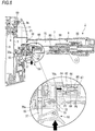
- FIG. 2 is an enlarged view of a trigger valve 30, a trigger 50, a timer switch 60, and a link member 70 according to the present embodiment
- FIG. 3A is an enlarged view of a timer 8 according to the present embodiment
- FIG. 3B is an enlarged view of a throttle part 90 constituting the timer according to the present embodiment.
- FIGS. 1 and 2 show a state before compressed air is supplied into a main chamber 15 of the nailing machine 1
- FIGS. 3A and 3B show a state while compressed air is supplied into the main chamber 15 of the nailing machine 1.
- the side where the contact arm 20 is provided is defined as the lower side of the nailing machine 1, and the opposite side thereof is defined as the upper side of the nailing machine 1. Further, the side where a housing 2 is provided is defined as the front side of the nailing machine 1, and the opposite side thereof is defined as the rear side of the nailing machine 1.
- the nailing machine 1 which is an example of a pneumatic tool, includes the cylindrical housing (tool body) 2 extending in an upper and lower direction, a grip 7 extending from a side surface of the housing 2 in a direction (front and rear direction) substantially orthogonal to an operating direction of the trigger 50 (to be described later), a nose 6 protruding downward from a lower end portion of the housing 2, and a magazine 22 for supplying a nail (not shown) to the nose 6.
- An air plug 13 to which one end portion of an air hose (not shown) can be connected is provided at a rear end portion of the grip 7.
- An air compressor (not shown) is connected to the other end portion of the air hose.
- a striking cylinder 3 is provided inside the housing 2, and a striking piston 4 is provided inside the striking cylinder 3 so as to be slidable in an upper and lower direction (axial direction).
- a rod-shaped striking driver 5 is integrally connected to a lower surface of the striking piston 4. The striking piston 4 is driven by compressed air supplied from the main chamber 15 and guides the striking driver 5 to the nose 6 to strike out a nail (not shown) supplied from the magazine 22 to the hose 6 toward an object.
- the main chamber 15 capable of containing compressed air is provided inside the grip 7. Compressed air is supplied from an air compressor into the main chamber 15 via an air hose connected to the air plug 13.
- a blowback chamber 18 is provided inside the housing 2 and on an outer peripheral portion on the lower side of the striking cylinder 3.
- the blowback chamber 18 contains compressed air for returning the striking piston 4 after the striking operation.
- the blowback chamber 18 communicates with the inside of the striking cylinder 3 via an inflow/discharge port 17 formed in a substantially intermediate portion in the upper and lower direction of the striking cylinder 3, and compressed air in the main chamber 15 is supplied into the blowback chamber 18 via the striking cylinder 3.
- the inflow/discharge port 17 is provided with a check valve 19 that allows air to flow from the striking cylinder 3 to the blowback chamber 18 but regulates the flow of air from the blowback chamber 18 to the striking cylinder 3.
- a head valve 9 having a substantially annular shape is provided on the upper side of the striking cylinder 3.
- the head valve 9 includes a head valve cylinder 10 provided at an upper end portion of the housing 2, and a head valve piston 11 arranged inside the head valve cylinder 10 so as to be slidable in the upper and lower direction.
- a recess 10a is provided on a peripheral edge of the head valve cylinder 10, and the head valve piston 11 is arranged in the recess 10a via a spring 16.
- the head valve piston 11 is urged downward by the spring 16, and a lower surface of the head valve piston 11 is in close contact with an upper end edge of the striking cylinder 3.
- the head valve piston 11 is in close contact with an inner wall surface of the recess 10a via an O-ring and forms a head valve chamber 9a which is a space between the head valve piston 11 and the recess 10a.
- the head valve chamber 9a communicates with a passage P2 (see FIG. 2 , to be described later) of the trigger valve 30 via a passage P1.
- the head valve piston 11 When the head valve piston 11 is located at a bottom dead center, that is, when a lower end portion of the head valve piston 11 is in close contact with an upper end edge of the striking cylinder 3, the inside of the main chamber 15 and the inside of the striking cylinder 3 are shut off.
- the head valve piston 11 When the head valve piston 11 is located at a top dead center, that is, when the lower end portion of the head valve piston 11 is separated from the upper end edge of the striking cylinder 3 to form a gap, the inside of the main chamber 15 and the inside of the striking cylinder 3 communicate with each other via the gap.
- a piston stop 12 made of, for example, an elastic member is provided inside the head valve piston 11.
- the piston stop 12 holds the striking piston 4 at the top dead center while reliably preventing the striking piston 4 from rebounding.
- the nailing machine 1 includes the trigger valve 30 that operates a drive part including the striking piston 4 and the head valve 9 and the like, the trigger 50 that performs a pulling operation (first operation) of operating the drive part via the trigger valve 30, the contact arm 20 that performs a pushing operation (second operation) of operating the drive part via the trigger valve 30, the timer 8 that measures the time when the drive part can be operated by operating the contact arm 20 and switches an operation mode of the drive part after the time has elapsed, the timer switch 60 that controls the operation of the timer 8, and the link member (transmitting member) 70 that is provided between the trigger 50 and the timer switch 60 and transmits the operation of the trigger 50 to the timer switch 60.
- the trigger valve 30 that operates a drive part including the striking piston 4 and the head valve 9 and the like
- the trigger 50 that performs a pulling operation (first operation) of operating the drive part via the trigger valve 30
- the contact arm 20 that performs a pushing operation (second operation) of operating the drive part via the trigger valve 30
- the trigger 50 is provided on a side surface of the housing 2 substantially in the middle in the upper and lower direction and on the front end side of the grip 7.
- the trigger 50 includes a trigger lever 52, a contact lever 54, and a pressing part 55.
- the trigger lever 52 is pivotably mounted via a shaft 51 provided in the housing 2 and pivots with the shaft 51 as a fulcrum in response to a pulling operation of the trigger lever 52 by an operator.
- the pressing part 55 presses one end portion 70a of the link member 70 by moving upward with the pivoting of the trigger lever 52.
- the contact lever 54 is pivotably mounted via a shaft 53 provided in the trigger lever 52 and presses a trigger valve stem 37 upward by pivoting with the shaft 53 as a fulcrum in conjunction with a pushing operation of the contact arm 20 against an object.
- the contact arm 20 is provided on the tip side of the nose 6 and is connected to a rod 20a.
- the contact arm 20 is configured to be reciprocally movable along an axial direction of the nose 6.
- the contact arm 20 is urged by a compression spring 20b so as to protrude downward from a tip portion of the nose 6 and relatively moves in the direction of compressing the compression spring 20b against the nose 6 by its tip portion being pressed against an object.
- An upper end portion of the rod 20a is in contact with the contact lever 54 and presses the contact lever 54 upward in conjunction with a pressing operation of the contact arm 20.
- the trigger valve 30 includes a pair of lower housing 34a and upper housing 34b, a pilot valve 35, the trigger valve stem 37, and a spring 38.
- the lower housing 34a and the upper housing 34b are formed of a substantially cylindrical body and are arranged to face each other with a predetermined interval.
- the passage P1 and the passage P2 communicating with a gap S1 (to be described later) are formed in the upper housing 34b.
- the pilot valve 35 and the trigger valve stem 37 are accommodated inside the lower housing 34a and the upper housing 34b.
- a cap 36 is arranged between the lower housing 34a and the trigger valve stem 37, and an inner surface of an upper end portion of the cap 36 is in close contact with an outer peripheral surface of a lower end portion of the pilot valve 35 via an O-ring 35e.
- the pilot valve 35 is configured to be reciprocally movable with respect to the upper housing 34b and the cap 36 in response to the operation of the trigger valve stem 37 and switches the communication or disconnection between the passage P1 on the side of the striking piston 4 and a passage P4 connected to the atmosphere on the side of the trigger valve 30.
- the gap S1 communicating with the passage P2 is provided between the pilot valve 35 and the upper housing 34b.
- a space inside the pilot valve 35 and the main chamber 15 communicate with each other via a passage P3 formed in an upper end portion of the pilot valve 35. Further, when an O-ring 35d mounted on the pilot valve 35 abuts on a lower end edge of the upper housing 34b, the upward movement of the pilot valve 35 is restricted, and a path between the gap S1 and the passage P4 is shut off.
- the trigger valve stem 37 is arranged inside the pilot valve 35 and the lower housing 34a via the spring 38 arranged on the pilot valve 35 and moves up and down in response to the pulling operation of the trigger 50 to switch the operation or non-operation of the pilot valve 35.
- the trigger valve stem 37 is configured by an elongated substantially cylindrical body extending in the upper and lower direction. The upper end side of the trigger valve stem 37 is urged downward by the spring 38, and the lower end portion of the trigger valve stem 37 is configured to be retractable to the side of the trigger 50 with respect to the cap 36.
- a trigger valve chamber 35a is provided between an inner wall surface of the cap 36 and a lower surface of the trigger valve stem 37.
- the trigger valve chamber 35a communicates with the main chamber 15 via the space inside the pilot valve 35 and the passage P3, and compressed air is stored in the trigger valve chamber 35a in a state (initial state) before the operation of the pilot valve 35.
- a valve operation control chamber 39 communicating with a passage P8 is provided between an outer peripheral surface of the cap 36 and an inner wall surface of the lower housing 34a.
- the timer switch 60 is a switch that is arranged inside the grip 7 between the timer 8 and the trigger 50 (the trigger valve 30) and is provided for operating the timer 8 in conjunction with the pulling operation of the trigger 50.
- the operating direction of the timer switch 60 is parallel to the extending direction of the grip 7 (grip axis).
- the timer switch 60 includes a timer switch housing 62, a timer switch stem 64, and a timer switch valve 66.
- the timer switch stem 64 and the timer switch valve 66 are accommodated in the timer switch housing 62 so as to be movable in a front and rear direction.
- a passage P5 communicating with the main chamber 15 is formed in the upper portion of the timer switch housing 62.
- the timer switch stem 64 is an elongated substantially cylindrical body extending in the front and rear direction.
- the timer switch stem 64 is configured to be movable in the front and rear direction with the pivoting of the link member 70, which pivots when the one end portion 70a of the link member 70 is pushed up by the pressing part 55 of the trigger 50 by operating the trigger lever 52.
- the tip portion of the timer switch stem 64 protrudes into a space S5 formed between the trigger valve 30 and the timer switch 60 and is in contact with the other end portion 70b of the link member 70.
- the timer switch valve 66 is arranged coaxially with the timer switch stem 64 and in contact with a rear end surface of the timer switch stem 64 and is urged toward the timer switch stem 64 by a spring 67.
- the timer switch valve 66 is configured to be movable in the front and rear direction in the timer switch housing 62 in response to the operation of the timer switch stem 64, and switches the communication or disconnection between a passage P6 and a passage P7 and between the passage P5 and the passage P6.
- the link member 70 is a member for converting the movement in the upper and lower direction based on the pulling operation of the trigger 50 into the movement in the front and rear direction for operating the timer switch 60.
- the link member 70 is configured by, for example, an inverted L-shaped plate member.
- the one end portion 70a of the link member 70 is provided in contact with the pressing part 55 of the trigger 50, and the other end portion 70b is in contact with the timer switch stem 64 of the timer switch 60.
- a curved portion of the link member 70 is pivotably supported by a shaft 72.
- the link member 70 is urged toward the trigger 50 by a spring (not shown) provided on the shaft 72 and air pressure applied to the timer switch stem 64.
- the other end side of the link member 70 is arranged in the space S5 formed between the trigger valve 30 and the timer switch 60, and the one end side of the link member 70 is arranged between the trigger valve 30 and the trigger 50.
- a first length L1 between an acting portion of the one end portion 70a of the link member 70 and the shaft 72 is set longer than a second length L2 between an acting portion of the other end portion 70b of the link member 70 and the shaft 72, and the operating amount of the trigger 50 is set longer than the operating amount of the timer switch stem 64 of the timer switch 60.
- the operating amount of the timer switch stem 64 of the timer switch 60 can be arbitrarily set by setting a ratio (lever ratio) of the first length L1 and the second length L2 of the link member 70.
- the timer 8 measures a predetermined time that allows the operation of the contact arm 20, and switches from an operation mode in which the striking of the nailing machine 1 can be performed to an operation mode in which the striking of the nailing machine 1 is prohibited after a lapse of a predetermined time.
- the timer 8 includes a timer piston 80 that generates compressed air for timekeeping as a load, and a timer piston spring 81 that urges the timer piston 80.
- An example of the predetermined time of the timer 8 is, for example, 3 seconds to 5 seconds, but the predetermined time is not limited to this.
- the timer 8 includes timer piston housings 82A to 82F that movably support the timer piston 80 and form a flow path through which air passes. Furthermore, the timer 8 includes a preset piston 83 that operates the timer piston 80, a preset piston spring 84 that urges the preset piston 83, and a preset piston housing 85 that movably supports the preset piston 83.
- the timer 8 is configured such that the timer piston 80 and the preset piston 83 can move along the extending direction of the grip 7.
- the timer piston housings 82A to 82F are arranged along the extending direction of the grip 7, the timer piston housing 82F movably supports the timer piston 80, and the timer piston housings 82A to 82E movably support a timer piston shaft 86 of the timer piston 80.
- a Y-ring 80a that has a Y-shaped cross section is fitted to the outer periphery of the timer piston 80.
- the Y-ring 80a rubs on an inner peripheral surface of the timer piston cylinder 80d.
- the timer 8 is configured such that the cylindrical timer piston housing 82C is inserted inside the timer piston housing 82B and the timer piston housing 82D, and the timer piston shaft 86 passes through the inside of the timer piston housing 82C.
- a gap between the timer piston housing 82B and the timer piston housing 82D communicates with a passage P9 connected to the main chamber 15 to form a flow path through which air passes.
- a gap between the timer piston housing 82B and the timer piston housing 82D, a gap between the timer piston housing 82B and the timer piston housing 82C, and a gap between the timer piston housing 82B and the timer piston housing 82A communicate the passage P9 and the passage P8 with each other to form a flow path through which air passes.
- a flow path forming recess 87b having a concave shape along the circumferential direction is formed in the vicinity of substantially the center of the timer piston shaft 86 in an axial direction.
- a flow path communicating the passage P9 and the passage P8 with each other is closed by an O-ring 87a in a state where the O-ring 87a provided on the timer piston housing 82B is in contact with the timer piston shaft 86.
- the flow path communicating the passage P9 and the passage P8 with each other is opened by a gap between the O-ring 87a and the flow path forming recess 87b when the timer piston 80 is moved to a position where the flow path forming recess 87b faces the O-ring 87a.
- the preset piston 83 is provided coaxially with the timer piston 80. As shown in FIG. 2 or the like, the preset piston housing 85 is connected to the blowback chamber 18 via the passage P6 formed between the preset piston housing 85 and the timer switch housing 62, the inside of the timer switch housing 62, and the passage P7 formed between the timer switch 60 and the blowback chamber 18, and the like.
- the throttle part 90 that adjusts the flow rate of air and discharges the air into the atmosphere is provided in the passage P10.
- the throttle part 90 is provided in the middle of the path of the passage P10 and includes a narrow portion 92 having a smaller flow path area (narrower width) than the other passages, and an adjustment member 94 mounted on the narrow portion 92.
- the adjustment member 94 is configured so that the flow path area, that is, the flow rate passing through a gap between a peripheral surface of the adjustment member 94 and a wall surface of the passage P10 can be adjusted by adjusting an insertion depth with respect to the narrow portion 92.
- the switching time of the operation mode of the nailing machine 1 is controlled by adjusting the flow rate of air compressed in the timer chamber 88 using the throttle part 90 and adjusting the moving speed of the timer piston 80 from a timer measurement start position to a timer measurement end position.
- a filter 96 for preventing the intrusion of lubricating oil or the like into the throttle part 90 is provided on the upstream side of the throttle part 90 in the passage P10.
- FIGS. 4 to 11 are operational views of the nailing machine 1 according to the present embodiment.
- the link member 70 can convert the movement in the upper and lower direction based on the pulling operation of the trigger 50 into the movement in the front and rear direction for pressing the timer switch stem 64.
- the timer switch stem 64 and the timer switch valve 66 are moved backward against an elastic force of the spring 67.
- the passage P6 is opened by the movement of an O-ring 68 of the timer switch valve 66, so that the flow path of air is switched, and the passage P6 and the passage P7 communicate with each other via the inside of the timer switch housing 62.
- the compressed air in the preset piston housing 85 flows into the blowback chamber 18 via the passage P6, the inside of the timer switch housing 62, and the passage P7.
- the compressed air introduced into the blowback chamber 18 is exhausted to the outside (into the atmosphere) via the inside of the striking cylinder 3.
- the preset piston 83 advances by the amount of exhausted air in the timer switch housing 62. Further, the timer piston 80 also advances with the movement of the preset piston 83. In this way, the measurement of the timer 8 is initiated.
- the compressed air in the timer chamber 88 is gradually exhausted into the atmosphere by passing through the throttle part 90 after flowing into the passage P10.
- the timer piston 80 gradually advances by the amount of exhausted air in the timer chamber 88.
- the timer 8 becomes time-out.
- the O-ring 87a is located at a position facing the flow path forming recess 87b, and the passage P9 and the passage P8 communicate with each other via a gap formed between the O-ring 87a and the flow path forming recess 87b.
- the compressed air in the main chamber 15 flows into the valve operation control chamber 39 via the passage P9, the flow path formed between the timer piston housings 82B and 82C, the gap between the O-ring 87a and the flow path forming recess 87b, and the passage P8.
- the cap 36 constituting the trigger valve 30 is pushed up by the compressed air introduced into the valve operation control chamber 39 and abuts on a lower surface of the pilot valve 35 on the upper side, so that the trigger valve chamber 35a (see FIG. 7 ) is closed.
- the tip portion of the contact arm 20 When the tip portion of the contact arm 20 is pressed against an object after the timer 8 shown in FIG. 8 becomes time-out, the striking operation of the nailing machine 1 is prohibited. Specifically, as shown in FIG. 9 , when the contact arm 20 is pressed against the object, the trigger valve stem 37 is pushed up by the contact lever 54 constituting the trigger 50. However, in the present embodiment, the trigger valve chamber 35a formed between the pilot valve 35 and the cap 36 is closed, and the downward movement of the pilot valve 35 is restricted.
- the striking operation is performed. Specifically, as shown in FIG. 10 , the contact lever 54 is pushed up when the contact arm 20 is pressed against the object. Along with this, the compressed air contained in the trigger valve chamber 35a (see FIG. 7 ) is exhausted into the atmosphere through a gap S2 between the trigger valve stem 37 and the cap 36.
- the upper end portion of the pilot valve 35 is urged downward by the compressed air in the main chamber 15 when the compressed air in the trigger valve chamber 35a is exhausted.
- the pilot valve 35 is lowered and its lower surface comes into contact with the inner wall surface of the cap 36.
- the O-ring 35d is also lowered with the operation of the pilot valve 35.
- the gap S1 and the passage P4 communicate with each other, and the compress air in the head valve chamber 9a on the side of the striking piston 4 is discharged into the atmosphere via the passage P1, the passage P2, the gap S1, and the passage P4.
- the lower end portion of the head valve piston 11 is pushed up by the compressed air in the main chamber 15, the compressed air in the main chamber 15 flows into the striking cylinder 3 through the gap between the striking cylinder 3 and the head valve piston 11, and as shown in FIG. 11 , the striking piston 4 is rapidly lowered in the striking cylinder 3, so that the striking driver 5 strikes a nail into the object.
- the compressed air in the striking cylinder 3 flows into the blowback chamber 18 through the inflow/discharge port 17.
- the compressed air introduced into the blowback chamber 18 acts on the lower surface of the striking piston 4 moved to the vicinity of the bottom dead center to return the striking piston 4 to the top dead center.
- the trigger valve stem 37 is lowered together with the contact lever 54, and compressed air is supplied again into the trigger valve chamber 35a and the head valve chamber 9a.
- the head valve piston 11 is lowered and returned to its original position, and the gap between the striking cylinder 3 and the head valve piston 11 is closed.
- the compressed air in the striking cylinder 3 flows into the blowback chamber 18 through the inflow/discharge port 17 and flows into the preset piston housing 85 via the passage P7, the inside of the timer switch housing 62, and the passage P6.
- the preset piston 83 and the timer piston 80 move to the timer measurement start position, and the timer 8 is reset.
- the timer 8 is reset using the compressed air for returning the striking piston 4.
- the link member 70 for transmitting the operation of the trigger 50 to the timer switch 60 is provided. Therefore, it is possible to convert the movement in the upper and lower direction based on the pulling operation of the trigger 50 into the movement in the front and rear direction for operating the timer switch 60. In this way, even when the timer 8 is arranged inside the grip 7 extending in a direction (direction substantially orthogonal to) different from the operating direction of the trigger 50, the operation load of the trigger 50 can be efficiently converted into the operation load for operating the timer 8.
- the timer switch 60 and the timer 8 can be operated via the link member 70 by pulling the trigger 50.
- the operation load of the trigger 50 can be reduced, and as a result, the operation load of the operator can be reduced.
- the operation load of the trigger 50 can be set depending on the setting (lever ratio) of the first length L1 between the shaft 72 of the link member 70 and the one end portion 70a and the second length L2 between the shaft 72 and the other end portion 70b.
- the timer switch 60 and the timer 8 are arranged together in the grip 7. Therefore, the operation load of the timer switch 60 can be transmitted to the timer 8. Further, the size of the nailing machine 1 can be reduced by arranging the timer 8 and the timer switch 60 together in the grip 7.
- the operating directions of the timer switch 60 and the timer 8 are arranged along the grip 7 (according to the grip axis). Therefore, the timer unit including the timer 8 and the timer switch 60 can be assembled to be inserted from the end (rear end) of the grip 7, which simplifies the assembly.
- the link member 70 is adopted as an example of the transmitting member
- the present disclosure is not limited to this.
- at least one or more parts of a gear and a cam may be used to convert the movement in the upper and lower direction based on the pulling operation of the trigger 50 into the movement in the front and rear direction for operating the timer switch 60 to operate the timer 8.
- the operation of the trigger 50 and the operation of the timer switch 60 may be linked by a string-shaped member such as a wire of a belt.
Abstract
Description
- The present disclosure relates to a pneumatic tool.
- Conventionally, a pneumatic tool has been used in which and a driver connected integrally with a striking piston strikes a nail into an object by reciprocating the striking piston slidably provided in a striking cylinder by using compressed air as a drive source.
- As a striking method of a pneumatic tool, for example, a contact striking in which a nail is struck into an object in a state where a contact arm is pressed against a member to be struck while a trigger is pulled, and a trigger striking in which a nail is struck into an object by pulling a trigger from a state in which a contact arm is pressed against an object are known.
- Here, in the case of performing the contact striking, a pneumatic tool may operate to erroneously fire a nail when the contact arm is inadvertently pushed while the trigger is stilled pulled. Therefore, in a pneumatic tool, in order to prevent unintentional erroneous firing of a nail, a timer is provided to limit the operation of the pneumatic tool when a certain period of time has elapsed in a state where a trigger is pulled.
- For example, a timer may be configured by an air valve or a circuit and the air valve or the circuit may be operated in response to a pulling operation of a trigger.
PTL 1 discloses a pneumatic fastener drive tool in which, when a workpiece contact element does not come into contact with a workpiece within a predetermined time, for example, 1 to 4 seconds, a sufficient amount of air flows out from a tank and an allowed valve assembly is closed through a pneumatic signal line to render the tool inoperable. - PTL 1:
JP-A-2002-254348 - By the way, in the pneumatic fastener drive tool disclosed in
PTL 1, it is also conceivable to reduce the size of the tool by arranging a safety mechanism including a timer in a space inside a grip used as a chamber, for example. However, when the timer is arranged in the space inside the chamber, an operating direction of the trigger and an operating direction of the timer may be different, and hence, there is a problem that the load direction of the trigger must be converted. Further, in the conventional pneumatic tool, the operation load of a timer switch for operating a timer is applied in addition to the operation load of the trigger, and hence, there is a problem that operation load of the operator increases. - Therefore, in order to solve the above problems, the present disclosure aims to provide a pneumatic tool that includes a timer operated by an operation of a trigger and can reduce the operation load of an operator by providing a transmitting mechanism for transmitting the operation of the trigger.
- According to an aspect of the present invention, there is provided a pneumatic tool including: a trigger configured to perform a first operation of operating a drive part; a contact member configured to perform a second operation of operating the drive part; a timer configured to measure the time during which the drive part can be operated by the second operation of the contact member and to switch the operation mode of the drive part after the time has elapsed; and a timer switch configured to control the operation of the timer, wherein the first operation of the trigger is transmitted to the timer switch using a transmitting member.
- According to the present disclosure, since the transmitting member for transmitting the operation of the trigger to the timer switch is provided, the load direction based on the operation of the trigger can be converted into the load direction for operating the timer switch.
- Further, according to the present disclosure, since the timer switch and the timer can be operated via the transmitting member by operating the trigger, the operation load of the operator can be reduced as compared with the case where both the trigger and the timer switch are operated.
-
-
FIG. 1 is a side sectional view of a nailing machine according to the present embodiment. -
FIG. 2 is an enlarged view of a trigger valve, a trigger, a timer switch, and a link member according to the present embodiment. -
FIG. 3A is an enlarged view of a timer according to the present embodiment. -
FIG. 3B is an enlarged view of a throttle part constituting the timer according to the present embodiment. -
FIG. 4 is an operation view of the nailing machine according to the present embodiment (the first view). -
FIG. 5 is an operation view of the nailing machine according to the present embodiment (the second view). -
FIG. 6 is an operation view of the nailing machine according to the present embodiment (the third view). -
FIG. 7 is an operation view of the nailing machine according to the present embodiment (the fourth view). -
FIG. 8 is an operation view of the nailing machine according to the present embodiment (the fifth view). -
FIG. 9 is an operation view of the nailing machine according to the present embodiment (the sixth view). -
FIG. 10 is an operation view of the nailing machine according to the present embodiment (the seventh view). -
FIG. 11 is an operation view of the nailing machine according to the present embodiment (the eighth view). - Hereinafter, a preferred embodiment of the present disclosure will be described in detail with reference to the accompanying drawings.
-
FIG. 1 is a side sectional view of a nailingmachine 1 according to the present embodiment,FIG. 2 is an enlarged view of atrigger valve 30, atrigger 50, atimer switch 60, and alink member 70 according to the present embodiment,FIG. 3A is an enlarged view of atimer 8 according to the present embodiment, andFIG. 3B is an enlarged view of athrottle part 90 constituting the timer according to the present embodiment.FIGS. 1 and2 show a state before compressed air is supplied into amain chamber 15 of the nailingmachine 1, andFIGS. 3A and 3B show a state while compressed air is supplied into themain chamber 15 of the nailingmachine 1. - In the present embodiment, considering the usage pattern of the nailing
machine 1, the side where thecontact arm 20 is provided is defined as the lower side of the nailingmachine 1, and the opposite side thereof is defined as the upper side of the nailingmachine 1. Further, the side where ahousing 2 is provided is defined as the front side of the nailingmachine 1, and the opposite side thereof is defined as the rear side of the nailingmachine 1. - As shown in
FIG. 1 , the nailingmachine 1, which is an example of a pneumatic tool, includes the cylindrical housing (tool body) 2 extending in an upper and lower direction, agrip 7 extending from a side surface of thehousing 2 in a direction (front and rear direction) substantially orthogonal to an operating direction of the trigger 50 (to be described later), anose 6 protruding downward from a lower end portion of thehousing 2, and amagazine 22 for supplying a nail (not shown) to thenose 6. An air plug 13 to which one end portion of an air hose (not shown) can be connected is provided at a rear end portion of thegrip 7. An air compressor (not shown) is connected to the other end portion of the air hose. - A
striking cylinder 3 is provided inside thehousing 2, and astriking piston 4 is provided inside thestriking cylinder 3 so as to be slidable in an upper and lower direction (axial direction). A rod-shapedstriking driver 5 is integrally connected to a lower surface of thestriking piston 4. Thestriking piston 4 is driven by compressed air supplied from themain chamber 15 and guides thestriking driver 5 to thenose 6 to strike out a nail (not shown) supplied from themagazine 22 to thehose 6 toward an object. - The
main chamber 15 capable of containing compressed air is provided inside thegrip 7. Compressed air is supplied from an air compressor into themain chamber 15 via an air hose connected to theair plug 13. - A
blowback chamber 18 is provided inside thehousing 2 and on an outer peripheral portion on the lower side of thestriking cylinder 3. Theblowback chamber 18 contains compressed air for returning thestriking piston 4 after the striking operation. Theblowback chamber 18 communicates with the inside of thestriking cylinder 3 via an inflow/discharge port 17 formed in a substantially intermediate portion in the upper and lower direction of thestriking cylinder 3, and compressed air in themain chamber 15 is supplied into theblowback chamber 18 via thestriking cylinder 3. The inflow/discharge port 17 is provided with acheck valve 19 that allows air to flow from thestriking cylinder 3 to theblowback chamber 18 but regulates the flow of air from theblowback chamber 18 to thestriking cylinder 3. - A
head valve 9 having a substantially annular shape is provided on the upper side of thestriking cylinder 3. Thehead valve 9 includes ahead valve cylinder 10 provided at an upper end portion of thehousing 2, and ahead valve piston 11 arranged inside thehead valve cylinder 10 so as to be slidable in the upper and lower direction. - A
recess 10a is provided on a peripheral edge of thehead valve cylinder 10, and thehead valve piston 11 is arranged in therecess 10a via aspring 16. Thehead valve piston 11 is urged downward by thespring 16, and a lower surface of thehead valve piston 11 is in close contact with an upper end edge of thestriking cylinder 3. Thehead valve piston 11 is in close contact with an inner wall surface of therecess 10a via an O-ring and forms ahead valve chamber 9a which is a space between thehead valve piston 11 and therecess 10a. Thehead valve chamber 9a communicates with a passage P2 (seeFIG. 2 , to be described later) of thetrigger valve 30 via a passage P1. - When the
head valve piston 11 is located at a bottom dead center, that is, when a lower end portion of thehead valve piston 11 is in close contact with an upper end edge of thestriking cylinder 3, the inside of themain chamber 15 and the inside of thestriking cylinder 3 are shut off. When thehead valve piston 11 is located at a top dead center, that is, when the lower end portion of thehead valve piston 11 is separated from the upper end edge of thestriking cylinder 3 to form a gap, the inside of themain chamber 15 and the inside of thestriking cylinder 3 communicate with each other via the gap. - A
piston stop 12 made of, for example, an elastic member is provided inside thehead valve piston 11. When thestriking piston 4 returns to the top dead center, thepiston stop 12 holds thestriking piston 4 at the top dead center while reliably preventing thestriking piston 4 from rebounding. - Further, as shown in
FIGS. 1 to 3B , the nailingmachine 1 includes thetrigger valve 30 that operates a drive part including thestriking piston 4 and thehead valve 9 and the like, thetrigger 50 that performs a pulling operation (first operation) of operating the drive part via thetrigger valve 30, thecontact arm 20 that performs a pushing operation (second operation) of operating the drive part via thetrigger valve 30, thetimer 8 that measures the time when the drive part can be operated by operating thecontact arm 20 and switches an operation mode of the drive part after the time has elapsed, thetimer switch 60 that controls the operation of thetimer 8, and the link member (transmitting member) 70 that is provided between thetrigger 50 and thetimer switch 60 and transmits the operation of thetrigger 50 to thetimer switch 60. - As shown in
FIG. 2 , thetrigger 50 is provided on a side surface of thehousing 2 substantially in the middle in the upper and lower direction and on the front end side of thegrip 7. Thetrigger 50 includes atrigger lever 52, acontact lever 54, and apressing part 55. - The
trigger lever 52 is pivotably mounted via ashaft 51 provided in thehousing 2 and pivots with theshaft 51 as a fulcrum in response to a pulling operation of thetrigger lever 52 by an operator. Thepressing part 55 presses oneend portion 70a of thelink member 70 by moving upward with the pivoting of thetrigger lever 52. Thecontact lever 54 is pivotably mounted via ashaft 53 provided in thetrigger lever 52 and presses a trigger valve stem 37 upward by pivoting with theshaft 53 as a fulcrum in conjunction with a pushing operation of thecontact arm 20 against an object. - As shown in
FIG. 1 , thecontact arm 20 is provided on the tip side of thenose 6 and is connected to arod 20a. Thecontact arm 20 is configured to be reciprocally movable along an axial direction of thenose 6. Thecontact arm 20 is urged by acompression spring 20b so as to protrude downward from a tip portion of thenose 6 and relatively moves in the direction of compressing thecompression spring 20b against thenose 6 by its tip portion being pressed against an object. An upper end portion of therod 20a is in contact with thecontact lever 54 and presses thecontact lever 54 upward in conjunction with a pressing operation of thecontact arm 20. - As shown in
FIG. 2 , thetrigger valve 30 includes a pair oflower housing 34a andupper housing 34b, apilot valve 35, thetrigger valve stem 37, and aspring 38. - The
lower housing 34a and theupper housing 34b are formed of a substantially cylindrical body and are arranged to face each other with a predetermined interval. The passage P1 and the passage P2 communicating with a gap S1 (to be described later) are formed in theupper housing 34b. - The
pilot valve 35 and the trigger valve stem 37 are accommodated inside thelower housing 34a and theupper housing 34b. Acap 36 is arranged between thelower housing 34a and thetrigger valve stem 37, and an inner surface of an upper end portion of thecap 36 is in close contact with an outer peripheral surface of a lower end portion of thepilot valve 35 via an O-ring 35e. - The
pilot valve 35 is configured to be reciprocally movable with respect to theupper housing 34b and thecap 36 in response to the operation of thetrigger valve stem 37 and switches the communication or disconnection between the passage P1 on the side of thestriking piston 4 and a passage P4 connected to the atmosphere on the side of thetrigger valve 30. The gap S1 communicating with the passage P2 is provided between thepilot valve 35 and theupper housing 34b. A space inside thepilot valve 35 and themain chamber 15 communicate with each other via a passage P3 formed in an upper end portion of thepilot valve 35. Further, when an O-ring 35d mounted on thepilot valve 35 abuts on a lower end edge of theupper housing 34b, the upward movement of thepilot valve 35 is restricted, and a path between the gap S1 and the passage P4 is shut off. - The trigger valve stem 37 is arranged inside the
pilot valve 35 and thelower housing 34a via thespring 38 arranged on thepilot valve 35 and moves up and down in response to the pulling operation of thetrigger 50 to switch the operation or non-operation of thepilot valve 35. The trigger valve stem 37 is configured by an elongated substantially cylindrical body extending in the upper and lower direction. The upper end side of the trigger valve stem 37 is urged downward by thespring 38, and the lower end portion of the trigger valve stem 37 is configured to be retractable to the side of thetrigger 50 with respect to thecap 36. - A
trigger valve chamber 35a is provided between an inner wall surface of thecap 36 and a lower surface of thetrigger valve stem 37. Thetrigger valve chamber 35a communicates with themain chamber 15 via the space inside thepilot valve 35 and the passage P3, and compressed air is stored in thetrigger valve chamber 35a in a state (initial state) before the operation of thepilot valve 35. A valveoperation control chamber 39 communicating with a passage P8 is provided between an outer peripheral surface of thecap 36 and an inner wall surface of thelower housing 34a. - As shown in
FIG. 2 , thetimer switch 60 is a switch that is arranged inside thegrip 7 between thetimer 8 and the trigger 50 (the trigger valve 30) and is provided for operating thetimer 8 in conjunction with the pulling operation of thetrigger 50. The operating direction of thetimer switch 60 is parallel to the extending direction of the grip 7 (grip axis). Thetimer switch 60 includes atimer switch housing 62, atimer switch stem 64, and atimer switch valve 66. - The
timer switch stem 64 and thetimer switch valve 66 are accommodated in thetimer switch housing 62 so as to be movable in a front and rear direction. A passage P5 communicating with themain chamber 15 is formed in the upper portion of thetimer switch housing 62. - The
timer switch stem 64 is an elongated substantially cylindrical body extending in the front and rear direction. Thetimer switch stem 64 is configured to be movable in the front and rear direction with the pivoting of thelink member 70, which pivots when the oneend portion 70a of thelink member 70 is pushed up by thepressing part 55 of thetrigger 50 by operating thetrigger lever 52. The tip portion of the timer switch stem 64 protrudes into a space S5 formed between thetrigger valve 30 and thetimer switch 60 and is in contact with theother end portion 70b of thelink member 70. - The
timer switch valve 66 is arranged coaxially with thetimer switch stem 64 and in contact with a rear end surface of thetimer switch stem 64 and is urged toward thetimer switch stem 64 by aspring 67. Thetimer switch valve 66 is configured to be movable in the front and rear direction in thetimer switch housing 62 in response to the operation of thetimer switch stem 64, and switches the communication or disconnection between a passage P6 and a passage P7 and between the passage P5 and the passage P6. - As shown in
FIG. 2 , thelink member 70 is a member for converting the movement in the upper and lower direction based on the pulling operation of thetrigger 50 into the movement in the front and rear direction for operating thetimer switch 60. Thelink member 70 is configured by, for example, an inverted L-shaped plate member. The oneend portion 70a of thelink member 70 is provided in contact with thepressing part 55 of thetrigger 50, and theother end portion 70b is in contact with the timer switch stem 64 of thetimer switch 60. A curved portion of thelink member 70 is pivotably supported by ashaft 72. Thelink member 70 is urged toward thetrigger 50 by a spring (not shown) provided on theshaft 72 and air pressure applied to thetimer switch stem 64. - The other end side of the
link member 70 is arranged in the space S5 formed between thetrigger valve 30 and thetimer switch 60, and the one end side of thelink member 70 is arranged between thetrigger valve 30 and thetrigger 50. In the present embodiment, a first length L1 between an acting portion of the oneend portion 70a of thelink member 70 and theshaft 72 is set longer than a second length L2 between an acting portion of theother end portion 70b of thelink member 70 and theshaft 72, and the operating amount of thetrigger 50 is set longer than the operating amount of the timer switch stem 64 of thetimer switch 60. In this way, in the present embodiment, the operating amount of the timer switch stem 64 of thetimer switch 60 can be arbitrarily set by setting a ratio (lever ratio) of the first length L1 and the second length L2 of thelink member 70. - As shown in
FIG. 3A , thetimer 8 measures a predetermined time that allows the operation of thecontact arm 20, and switches from an operation mode in which the striking of the nailingmachine 1 can be performed to an operation mode in which the striking of the nailingmachine 1 is prohibited after a lapse of a predetermined time. Thetimer 8 includes atimer piston 80 that generates compressed air for timekeeping as a load, and atimer piston spring 81 that urges thetimer piston 80. An example of the predetermined time of thetimer 8 is, for example, 3 seconds to 5 seconds, but the predetermined time is not limited to this. - Further, the
timer 8 includestimer piston housings 82A to 82F that movably support thetimer piston 80 and form a flow path through which air passes. Furthermore, thetimer 8 includes apreset piston 83 that operates thetimer piston 80, apreset piston spring 84 that urges thepreset piston 83, and apreset piston housing 85 that movably supports thepreset piston 83. - The
timer 8 is configured such that thetimer piston 80 and thepreset piston 83 can move along the extending direction of thegrip 7. In thetimer 8, thetimer piston housings 82A to 82F are arranged along the extending direction of thegrip 7, thetimer piston housing 82F movably supports thetimer piston 80, and thetimer piston housings 82A to 82E movably support atimer piston shaft 86 of thetimer piston 80. - A Y-
ring 80a that has a Y-shaped cross section is fitted to the outer periphery of thetimer piston 80. The Y-ring 80a rubs on an inner peripheral surface of the timer piston cylinder 80d. - The
timer 8 is configured such that the cylindricaltimer piston housing 82C is inserted inside thetimer piston housing 82B and thetimer piston housing 82D, and thetimer piston shaft 86 passes through the inside of thetimer piston housing 82C. - Further, in the
timer 8, a gap between thetimer piston housing 82B and thetimer piston housing 82D communicates with a passage P9 connected to themain chamber 15 to form a flow path through which air passes. Further, in thetimer 8, a gap between thetimer piston housing 82B and thetimer piston housing 82D, a gap between thetimer piston housing 82B and thetimer piston housing 82C, and a gap between thetimer piston housing 82B and thetimer piston housing 82A communicate the passage P9 and the passage P8 with each other to form a flow path through which air passes. - In the
timer piston 80, a flowpath forming recess 87b having a concave shape along the circumferential direction is formed in the vicinity of substantially the center of thetimer piston shaft 86 in an axial direction. - In the
timer 8, a flow path communicating the passage P9 and the passage P8 with each other is closed by an O-ring 87a in a state where the O-ring 87a provided on thetimer piston housing 82B is in contact with thetimer piston shaft 86. On the contrary, in thetimer 8, the flow path communicating the passage P9 and the passage P8 with each other is opened by a gap between the O-ring 87a and the flowpath forming recess 87b when thetimer piston 80 is moved to a position where the flowpath forming recess 87b faces the O-ring 87a. - The
preset piston 83 is provided coaxially with thetimer piston 80. As shown inFIG. 2 or the like, thepreset piston housing 85 is connected to theblowback chamber 18 via the passage P6 formed between thepreset piston housing 85 and thetimer switch housing 62, the inside of thetimer switch housing 62, and the passage P7 formed between thetimer switch 60 and theblowback chamber 18, and the like. - As shown in
FIGS. 3A and 3B , a passage P10 into which the air compressed in atimer chamber 88 flows by the operation of thetimer piston 80 communicates with thetimer chamber 88. Thethrottle part 90 that adjusts the flow rate of air and discharges the air into the atmosphere is provided in the passage P10. Thethrottle part 90 is provided in the middle of the path of the passage P10 and includes anarrow portion 92 having a smaller flow path area (narrower width) than the other passages, and anadjustment member 94 mounted on thenarrow portion 92. Theadjustment member 94 is configured so that the flow path area, that is, the flow rate passing through a gap between a peripheral surface of theadjustment member 94 and a wall surface of the passage P10 can be adjusted by adjusting an insertion depth with respect to thenarrow portion 92. In this way, in the present embodiment, the switching time of the operation mode of the nailingmachine 1 is controlled by adjusting the flow rate of air compressed in thetimer chamber 88 using thethrottle part 90 and adjusting the moving speed of thetimer piston 80 from a timer measurement start position to a timer measurement end position. Afilter 96 for preventing the intrusion of lubricating oil or the like into thethrottle part 90 is provided on the upstream side of thethrottle part 90 in the passage P10. - Next, the operation of the nailing
machine 1 according to the present embodiment will be described.FIGS. 4 to 11 are operational views of the nailingmachine 1 according to the present embodiment. - When an air chuck of an air hose is connected to the
air plug 13, as shown inFIG. 4 , compressed air is supplied from an air compressor into themain chamber 15. The compressed air supplied into themain chamber 15 flows into thepreset piston housing 85 via the passage P5, the inside of thetimer switch housing 62, and the passage P6. Thepreset piston 83 and thetimer piston 80 are pushed backward and retracted by the compressed air introduced into thepreset piston housing 85 and are stopped at the timer measurement start position. In this way, thetimer 8 is put into a standby state. - As shown in
FIG. 6 , when thetrigger 50 is pulled by an operator, the oneend portion 70a of thelink member 70 is pushed up by thepressing part 55. Along with this, thelink member 70 pivots in a clockwise direction with theshaft 72 as a fulcrum, and thetimer switch stem 64 is pushed backward by theother end portion 70b of thelink member 70. In this way, in the present embodiment, thelink member 70 can convert the movement in the upper and lower direction based on the pulling operation of thetrigger 50 into the movement in the front and rear direction for pressing thetimer switch stem 64. Thetimer switch stem 64 and thetimer switch valve 66 are moved backward against an elastic force of thespring 67. In this way, the passage P6 is opened by the movement of an O-ring 68 of thetimer switch valve 66, so that the flow path of air is switched, and the passage P6 and the passage P7 communicate with each other via the inside of thetimer switch housing 62. - As shown in
FIG. 7 , when thetimer switch 60 is operated, the compressed air in thepreset piston housing 85 flows into theblowback chamber 18 via the passage P6, the inside of thetimer switch housing 62, and the passage P7. The compressed air introduced into theblowback chamber 18 is exhausted to the outside (into the atmosphere) via the inside of thestriking cylinder 3. - Along with this, the
preset piston 83 advances by the amount of exhausted air in thetimer switch housing 62. Further, thetimer piston 80 also advances with the movement of thepreset piston 83. In this way, the measurement of thetimer 8 is initiated. In the present embodiment, due to the movement of thetimer piston 80, the compressed air in thetimer chamber 88 is gradually exhausted into the atmosphere by passing through thethrottle part 90 after flowing into the passage P10. Thetimer piston 80 gradually advances by the amount of exhausted air in thetimer chamber 88. - As shown in
FIG. 8 , when thetimer piston 80 advances and reaches the timer measurement end position, thetimer 8 becomes time-out. At this time, the O-ring 87a is located at a position facing the flowpath forming recess 87b, and the passage P9 and the passage P8 communicate with each other via a gap formed between the O-ring 87a and the flowpath forming recess 87b. In this way, the compressed air in themain chamber 15 flows into the valveoperation control chamber 39 via the passage P9, the flow path formed between thetimer piston housings ring 87a and the flowpath forming recess 87b, and the passage P8. Thecap 36 constituting thetrigger valve 30 is pushed up by the compressed air introduced into the valveoperation control chamber 39 and abuts on a lower surface of thepilot valve 35 on the upper side, so that thetrigger valve chamber 35a (seeFIG. 7 ) is closed. - When the tip portion of the
contact arm 20 is pressed against an object after thetimer 8 shown inFIG. 8 becomes time-out, the striking operation of the nailingmachine 1 is prohibited. Specifically, as shown inFIG. 9 , when thecontact arm 20 is pressed against the object, the trigger valve stem 37 is pushed up by thecontact lever 54 constituting thetrigger 50. However, in the present embodiment, thetrigger valve chamber 35a formed between thepilot valve 35 and thecap 36 is closed, and the downward movement of thepilot valve 35 is restricted. Therefore, since the flow path communicating the passage P2 (the gap S1) and the passage P4 with each other is shut off by an O-ring 35d even when the trigger valve stem 37 is pushed up, the compressed air in thehead valve chamber 9a is not discharged into the outside atmosphere, and thestriking piston 4 does not operate. That is, the striking operation of the nailingmachine 1 is prohibited. - When the
contact arm 20 is pressed against the object before thetimer 8 shown inFIG. 7 becomes time-out, the striking operation is performed. Specifically, as shown inFIG. 10 , thecontact lever 54 is pushed up when thecontact arm 20 is pressed against the object. Along with this, the compressed air contained in thetrigger valve chamber 35a (seeFIG. 7 ) is exhausted into the atmosphere through a gap S2 between thetrigger valve stem 37 and thecap 36. - Subsequently, the upper end portion of the
pilot valve 35 is urged downward by the compressed air in themain chamber 15 when the compressed air in thetrigger valve chamber 35a is exhausted. In this way, thepilot valve 35 is lowered and its lower surface comes into contact with the inner wall surface of thecap 36. The O-ring 35d is also lowered with the operation of thepilot valve 35. In this way, the gap S1 and the passage P4 communicate with each other, and the compress air in thehead valve chamber 9a on the side of thestriking piston 4 is discharged into the atmosphere via the passage P1, the passage P2, the gap S1, and the passage P4. - In this way, the lower end portion of the
head valve piston 11 is pushed up by the compressed air in themain chamber 15, the compressed air in themain chamber 15 flows into thestriking cylinder 3 through the gap between thestriking cylinder 3 and thehead valve piston 11, and as shown inFIG. 11 , thestriking piston 4 is rapidly lowered in thestriking cylinder 3, so that thestriking driver 5 strikes a nail into the object. While thestriking piston 4 moves to the bottom dead center, the compressed air in thestriking cylinder 3 flows into theblowback chamber 18 through the inflow/discharge port 17. The compressed air introduced into theblowback chamber 18 acts on the lower surface of thestriking piston 4 moved to the vicinity of the bottom dead center to return thestriking piston 4 to the top dead center. - Further, when the pressing of the
contact arm 20 against the object is released, the trigger valve stem 37 is lowered together with thecontact lever 54, and compressed air is supplied again into thetrigger valve chamber 35a and thehead valve chamber 9a. Along with this, thehead valve piston 11 is lowered and returned to its original position, and the gap between thestriking cylinder 3 and thehead valve piston 11 is closed. - Further, as shown in
FIG. 11 , while thestriking piston 4 is moved to the bottom dead center, the compressed air in thestriking cylinder 3 flows into theblowback chamber 18 through the inflow/discharge port 17 and flows into thepreset piston housing 85 via the passage P7, the inside of thetimer switch housing 62, and the passage P6. In this way, thepreset piston 83 and thetimer piston 80 move to the timer measurement start position, and thetimer 8 is reset. In this way, in the present embodiment, thetimer 8 is reset using the compressed air for returning thestriking piston 4. - As described above, according to the present disclosure, the
link member 70 for transmitting the operation of thetrigger 50 to thetimer switch 60 is provided. Therefore, it is possible to convert the movement in the upper and lower direction based on the pulling operation of thetrigger 50 into the movement in the front and rear direction for operating thetimer switch 60. In this way, even when thetimer 8 is arranged inside thegrip 7 extending in a direction (direction substantially orthogonal to) different from the operating direction of thetrigger 50, the operation load of thetrigger 50 can be efficiently converted into the operation load for operating thetimer 8. - Further, according to the present disclosure, the
timer switch 60 and thetimer 8 can be operated via thelink member 70 by pulling thetrigger 50. In this way, the operation load of thetrigger 50 can be reduced, and as a result, the operation load of the operator can be reduced. Further, the operation load of thetrigger 50 can be set depending on the setting (lever ratio) of the first length L1 between theshaft 72 of thelink member 70 and the oneend portion 70a and the second length L2 between theshaft 72 and theother end portion 70b. - Further, according to the present disclosure, the
timer switch 60 and thetimer 8 are arranged together in thegrip 7. Therefore, the operation load of thetimer switch 60 can be transmitted to thetimer 8. Further, the size of the nailingmachine 1 can be reduced by arranging thetimer 8 and thetimer switch 60 together in thegrip 7. - Further, according to the present disclosure, the operating directions of the
timer switch 60 and thetimer 8 are arranged along the grip 7 (according to the grip axis). Therefore, the timer unit including thetimer 8 and thetimer switch 60 can be assembled to be inserted from the end (rear end) of thegrip 7, which simplifies the assembly. - Although the preferred embodiment of the present disclosure has been described in detail with reference to the accompanying drawings, the technical scope of the present disclosure is not limited to such examples. The technical ideas from which any person who has ordinary knowledge in the technical field of the present disclosure can lead to various modifications and changes within the scope of the technical ideas stated in the claims belong to the technical scope of the present disclosure.
- For example, although the case where the
link member 70 is adopted as an example of the transmitting member has been described in the above embodiment, the present disclosure is not limited to this. For example, at least one or more parts of a gear and a cam may be used to convert the movement in the upper and lower direction based on the pulling operation of thetrigger 50 into the movement in the front and rear direction for operating thetimer switch 60 to operate thetimer 8. Further, needless to say, the operation of thetrigger 50 and the operation of thetimer switch 60 may be linked by a string-shaped member such as a wire of a belt.
Claims (6)
- A pneumatic tool comprising:a trigger configured to perform a first operation of operating a drive part;a contact member configured to perform a second operation of operating the drive part;a timer configured to measure the time during which the drive part can be operated by the second operation of the contact member and to switch the operation mode of the drive part after the time has elapsed; anda timer switch configured to control the operation of the timer,wherein the first operation of the trigger is transmitted to the timer switch using a transmitting member.
- The pneumatic tool according to claim 1,
wherein an operating direction of the trigger and an operating direction of the timer switch are different. - The pneumatic tool according to claim 1, comprising:a tool body in which the drive part is accommodated; anda grip provided on a side surface of the tool body and extending in a direction intersecting an operating direction of the trigger,wherein the timer switch is disposed in the grip.
- The pneumatic tool according to any one of claims 1 to 3,
wherein an operating amount of the trigger is longer than an operating amount of the timer switch. - The pneumatic tool according to claim 3,
wherein an operating direction of the timer switch is parallel to an extending direction of the grip. - The pneumatic tool according to any one of claims 1 to 4,wherein the transmitting member is pivotably provided with a shaft as a fulcrum, andwherein one end portion of the transmitting member comes into contact with the trigger, and the other end portion of the transmitting member comes into contact with the timer switch.
Applications Claiming Priority (1)
| Application Number | Priority Date | Filing Date | Title |
|---|---|---|---|
| JP2020113616A JP7463883B2 (en) | 2020-06-30 | 2020-06-30 | Air Tools |
Publications (1)
| Publication Number | Publication Date |
|---|---|
| EP3932618A1 true EP3932618A1 (en) | 2022-01-05 |
Family
ID=76708104
Family Applications (1)
| Application Number | Title | Priority Date | Filing Date |
|---|---|---|---|
| EP21182501.3A Pending EP3932618A1 (en) | 2020-06-30 | 2021-06-29 | Pneumatic tool |
Country Status (4)
| Country | Link |
|---|---|
| US (1) | US20210402578A1 (en) |
| EP (1) | EP3932618A1 (en) |
| JP (1) | JP7463883B2 (en) |
| TW (1) | TW202216378A (en) |
Citations (1)
| Publication number | Priority date | Publication date | Assignee | Title |
|---|---|---|---|---|
| EP3552767A1 (en) * | 2018-03-26 | 2019-10-16 | TTI (Macao Commercial Offshore) Limited | Pneumatic fastener driver |
Family Cites Families (4)
| Publication number | Priority date | Publication date | Assignee | Title |
|---|---|---|---|---|
| JP3287172B2 (en) * | 1995-04-05 | 2002-05-27 | マックス株式会社 | Nailer trigger device |
| JP6408944B2 (en) | 2015-03-24 | 2018-10-17 | 株式会社マキタ | Driving tool |
| FR3045784B1 (en) * | 2015-12-18 | 2019-03-22 | Illinois Tool Works Inc | METHOD FOR CONTROLLING THE ACTUATION OF A GAS FASTENING TOOL AND CORRESPONDING DEVICE |
| JP6833565B2 (en) | 2017-03-01 | 2021-02-24 | 株式会社マキタ | Driving tool |
-
2020
- 2020-06-30 JP JP2020113616A patent/JP7463883B2/en active Active
-
2021
- 2021-06-29 US US17/361,731 patent/US20210402578A1/en active Pending
- 2021-06-29 TW TW110123775A patent/TW202216378A/en unknown
- 2021-06-29 EP EP21182501.3A patent/EP3932618A1/en active Pending
Patent Citations (1)
| Publication number | Priority date | Publication date | Assignee | Title |
|---|---|---|---|---|
| EP3552767A1 (en) * | 2018-03-26 | 2019-10-16 | TTI (Macao Commercial Offshore) Limited | Pneumatic fastener driver |
Also Published As
| Publication number | Publication date |
|---|---|
| US20210402578A1 (en) | 2021-12-30 |
| JP2022012074A (en) | 2022-01-17 |
| JP7463883B2 (en) | 2024-04-09 |
| TW202216378A (en) | 2022-05-01 |
Similar Documents
| Publication | Publication Date | Title |
|---|---|---|
| JP7043771B2 (en) | Driving tool | |
| US11707825B2 (en) | Pneumatic tool | |
| EP3932618A1 (en) | Pneumatic tool | |
| US20230278178A1 (en) | Pneumatic tool | |
| TWI680846B (en) | Pneumatic nailer with single and contact triggering | |
| CN111225769B (en) | Pneumatic nailing gun with safety regulating element | |
| US11780067B2 (en) | Pneumatic tool | |
| EP3461591B1 (en) | Driving tool | |
| JP2023014364A (en) | Air pressure tool | |
| AU2018361393A1 (en) | Pneumatic nail gun having a safety valve assembly | |
| JP7205372B2 (en) | pneumatic tools | |
| JPH09272026A (en) | Control valve device and fastener drive device with start-up sensibility adjusting device | |
| JP2022001393A (en) | Driving machine | |
| JPH0616670Y2 (en) | Safety device for nailer | |
| JPWO2019168075A1 (en) | Fluid dampers and driving tools | |
| JPS6133673B2 (en) | ||
| JP2003048175A (en) | Safety device for air impact driver |
Legal Events
| Date | Code | Title | Description |
|---|---|---|---|
| PUAI | Public reference made under article 153(3) epc to a published international application that has entered the european phase |
Free format text: ORIGINAL CODE: 0009012 |
|
| STAA | Information on the status of an ep patent application or granted ep patent |
Free format text: STATUS: THE APPLICATION HAS BEEN PUBLISHED |
|
| AK | Designated contracting states |
Kind code of ref document: A1 Designated state(s): AL AT BE BG CH CY CZ DE DK EE ES FI FR GB GR HR HU IE IS IT LI LT LU LV MC MK MT NL NO PL PT RO RS SE SI SK SM TR |
|
| B565 | Issuance of search results under rule 164(2) epc |
Effective date: 20211125 |
|
| STAA | Information on the status of an ep patent application or granted ep patent |
Free format text: STATUS: REQUEST FOR EXAMINATION WAS MADE |
|
| 17P | Request for examination filed |
Effective date: 20220705 |
|
| RBV | Designated contracting states (corrected) |
Designated state(s): AL AT BE BG CH CY CZ DE DK EE ES FI FR GB GR HR HU IE IS IT LI LT LU LV MC MK MT NL NO PL PT RO RS SE SI SK SM TR |
|
| GRAP | Despatch of communication of intention to grant a patent |
Free format text: ORIGINAL CODE: EPIDOSNIGR1 |
|
| STAA | Information on the status of an ep patent application or granted ep patent |
Free format text: STATUS: GRANT OF PATENT IS INTENDED |
|
| INTG | Intention to grant announced |
Effective date: 20240119 |