EP3932602A1 - Welding repair method for precipitation-strengthened cast product - Google Patents
Welding repair method for precipitation-strengthened cast product Download PDFInfo
- Publication number
- EP3932602A1 EP3932602A1 EP19917077.0A EP19917077A EP3932602A1 EP 3932602 A1 EP3932602 A1 EP 3932602A1 EP 19917077 A EP19917077 A EP 19917077A EP 3932602 A1 EP3932602 A1 EP 3932602A1
- Authority
- EP
- European Patent Office
- Prior art keywords
- weld layer
- welding
- cast product
- precipitation
- formation step
- Prior art date
- Legal status (The legal status is an assumption and is not a legal conclusion. Google has not performed a legal analysis and makes no representation as to the accuracy of the status listed.)
- Withdrawn
Links
Images




Classifications
-
- B—PERFORMING OPERATIONS; TRANSPORTING
- B23—MACHINE TOOLS; METAL-WORKING NOT OTHERWISE PROVIDED FOR
- B23K—SOLDERING OR UNSOLDERING; WELDING; CLADDING OR PLATING BY SOLDERING OR WELDING; CUTTING BY APPLYING HEAT LOCALLY, e.g. FLAME CUTTING; WORKING BY LASER BEAM
- B23K28/00—Welding or cutting not covered by groups B23K5/00 - B23K26/00
- B23K28/02—Combined welding or cutting procedures or apparatus
-
- B—PERFORMING OPERATIONS; TRANSPORTING
- B23—MACHINE TOOLS; METAL-WORKING NOT OTHERWISE PROVIDED FOR
- B23K—SOLDERING OR UNSOLDERING; WELDING; CLADDING OR PLATING BY SOLDERING OR WELDING; CUTTING BY APPLYING HEAT LOCALLY, e.g. FLAME CUTTING; WORKING BY LASER BEAM
- B23K9/00—Arc welding or cutting
- B23K9/04—Welding for other purposes than joining, e.g. built-up welding
- B23K9/044—Built-up welding on three-dimensional surfaces
-
- B—PERFORMING OPERATIONS; TRANSPORTING
- B22—CASTING; POWDER METALLURGY
- B22F—WORKING METALLIC POWDER; MANUFACTURE OF ARTICLES FROM METALLIC POWDER; MAKING METALLIC POWDER; APPARATUS OR DEVICES SPECIALLY ADAPTED FOR METALLIC POWDER
- B22F10/00—Additive manufacturing of workpieces or articles from metallic powder
- B22F10/20—Direct sintering or melting
- B22F10/25—Direct deposition of metal particles, e.g. direct metal deposition [DMD] or laser engineered net shaping [LENS]
-
- B—PERFORMING OPERATIONS; TRANSPORTING
- B22—CASTING; POWDER METALLURGY
- B22F—WORKING METALLIC POWDER; MANUFACTURE OF ARTICLES FROM METALLIC POWDER; MAKING METALLIC POWDER; APPARATUS OR DEVICES SPECIALLY ADAPTED FOR METALLIC POWDER
- B22F5/00—Manufacture of workpieces or articles from metallic powder characterised by the special shape of the product
- B22F5/04—Manufacture of workpieces or articles from metallic powder characterised by the special shape of the product of turbine blades
-
- B—PERFORMING OPERATIONS; TRANSPORTING
- B22—CASTING; POWDER METALLURGY
- B22F—WORKING METALLIC POWDER; MANUFACTURE OF ARTICLES FROM METALLIC POWDER; MAKING METALLIC POWDER; APPARATUS OR DEVICES SPECIALLY ADAPTED FOR METALLIC POWDER
- B22F7/00—Manufacture of composite layers, workpieces, or articles, comprising metallic powder, by sintering the powder, with or without compacting wherein at least one part is obtained by sintering or compression
- B22F7/06—Manufacture of composite layers, workpieces, or articles, comprising metallic powder, by sintering the powder, with or without compacting wherein at least one part is obtained by sintering or compression of composite workpieces or articles from parts, e.g. to form tipped tools
- B22F7/08—Manufacture of composite layers, workpieces, or articles, comprising metallic powder, by sintering the powder, with or without compacting wherein at least one part is obtained by sintering or compression of composite workpieces or articles from parts, e.g. to form tipped tools with one or more parts not made from powder
-
- B—PERFORMING OPERATIONS; TRANSPORTING
- B23—MACHINE TOOLS; METAL-WORKING NOT OTHERWISE PROVIDED FOR
- B23K—SOLDERING OR UNSOLDERING; WELDING; CLADDING OR PLATING BY SOLDERING OR WELDING; CUTTING BY APPLYING HEAT LOCALLY, e.g. FLAME CUTTING; WORKING BY LASER BEAM
- B23K26/00—Working by laser beam, e.g. welding, cutting or boring
- B23K26/0006—Working by laser beam, e.g. welding, cutting or boring taking account of the properties of the material involved
-
- B—PERFORMING OPERATIONS; TRANSPORTING
- B23—MACHINE TOOLS; METAL-WORKING NOT OTHERWISE PROVIDED FOR
- B23K—SOLDERING OR UNSOLDERING; WELDING; CLADDING OR PLATING BY SOLDERING OR WELDING; CUTTING BY APPLYING HEAT LOCALLY, e.g. FLAME CUTTING; WORKING BY LASER BEAM
- B23K26/00—Working by laser beam, e.g. welding, cutting or boring
- B23K26/34—Laser welding for purposes other than joining
-
- B—PERFORMING OPERATIONS; TRANSPORTING
- B23—MACHINE TOOLS; METAL-WORKING NOT OTHERWISE PROVIDED FOR
- B23K—SOLDERING OR UNSOLDERING; WELDING; CLADDING OR PLATING BY SOLDERING OR WELDING; CUTTING BY APPLYING HEAT LOCALLY, e.g. FLAME CUTTING; WORKING BY LASER BEAM
- B23K26/00—Working by laser beam, e.g. welding, cutting or boring
- B23K26/34—Laser welding for purposes other than joining
- B23K26/342—Build-up welding
-
- B—PERFORMING OPERATIONS; TRANSPORTING
- B23—MACHINE TOOLS; METAL-WORKING NOT OTHERWISE PROVIDED FOR
- B23K—SOLDERING OR UNSOLDERING; WELDING; CLADDING OR PLATING BY SOLDERING OR WELDING; CUTTING BY APPLYING HEAT LOCALLY, e.g. FLAME CUTTING; WORKING BY LASER BEAM
- B23K31/00—Processes relevant to this subclass, specially adapted for particular articles or purposes, but not covered by any single one of main groups B23K1/00 - B23K28/00
-
- B—PERFORMING OPERATIONS; TRANSPORTING
- B23—MACHINE TOOLS; METAL-WORKING NOT OTHERWISE PROVIDED FOR
- B23K—SOLDERING OR UNSOLDERING; WELDING; CLADDING OR PLATING BY SOLDERING OR WELDING; CUTTING BY APPLYING HEAT LOCALLY, e.g. FLAME CUTTING; WORKING BY LASER BEAM
- B23K35/00—Rods, electrodes, materials, or media, for use in soldering, welding, or cutting
- B23K35/22—Rods, electrodes, materials, or media, for use in soldering, welding, or cutting characterised by the composition or nature of the material
- B23K35/24—Selection of soldering or welding materials proper
- B23K35/30—Selection of soldering or welding materials proper with the principal constituent melting at less than 1550°C
- B23K35/3033—Ni as the principal constituent
-
- B—PERFORMING OPERATIONS; TRANSPORTING
- B23—MACHINE TOOLS; METAL-WORKING NOT OTHERWISE PROVIDED FOR
- B23K—SOLDERING OR UNSOLDERING; WELDING; CLADDING OR PLATING BY SOLDERING OR WELDING; CUTTING BY APPLYING HEAT LOCALLY, e.g. FLAME CUTTING; WORKING BY LASER BEAM
- B23K9/00—Arc welding or cutting
- B23K9/04—Welding for other purposes than joining, e.g. built-up welding
-
- B—PERFORMING OPERATIONS; TRANSPORTING
- B23—MACHINE TOOLS; METAL-WORKING NOT OTHERWISE PROVIDED FOR
- B23K—SOLDERING OR UNSOLDERING; WELDING; CLADDING OR PLATING BY SOLDERING OR WELDING; CUTTING BY APPLYING HEAT LOCALLY, e.g. FLAME CUTTING; WORKING BY LASER BEAM
- B23K9/00—Arc welding or cutting
- B23K9/16—Arc welding or cutting making use of shielding gas
- B23K9/173—Arc welding or cutting making use of shielding gas and of a consumable electrode
-
- B—PERFORMING OPERATIONS; TRANSPORTING
- B23—MACHINE TOOLS; METAL-WORKING NOT OTHERWISE PROVIDED FOR
- B23P—METAL-WORKING NOT OTHERWISE PROVIDED FOR; COMBINED OPERATIONS; UNIVERSAL MACHINE TOOLS
- B23P6/00—Restoring or reconditioning objects
- B23P6/002—Repairing turbine components, e.g. moving or stationary blades, rotors
- B23P6/007—Repairing turbine components, e.g. moving or stationary blades, rotors using only additive methods, e.g. build-up welding
-
- B—PERFORMING OPERATIONS; TRANSPORTING
- B33—ADDITIVE MANUFACTURING TECHNOLOGY
- B33Y—ADDITIVE MANUFACTURING, i.e. MANUFACTURING OF THREE-DIMENSIONAL [3D] OBJECTS BY ADDITIVE DEPOSITION, ADDITIVE AGGLOMERATION OR ADDITIVE LAYERING, e.g. BY 3D PRINTING, STEREOLITHOGRAPHY OR SELECTIVE LASER SINTERING
- B33Y10/00—Processes of additive manufacturing
-
- B—PERFORMING OPERATIONS; TRANSPORTING
- B33—ADDITIVE MANUFACTURING TECHNOLOGY
- B33Y—ADDITIVE MANUFACTURING, i.e. MANUFACTURING OF THREE-DIMENSIONAL [3D] OBJECTS BY ADDITIVE DEPOSITION, ADDITIVE AGGLOMERATION OR ADDITIVE LAYERING, e.g. BY 3D PRINTING, STEREOLITHOGRAPHY OR SELECTIVE LASER SINTERING
- B33Y80/00—Products made by additive manufacturing
-
- C—CHEMISTRY; METALLURGY
- C22—METALLURGY; FERROUS OR NON-FERROUS ALLOYS; TREATMENT OF ALLOYS OR NON-FERROUS METALS
- C22C—ALLOYS
- C22C19/00—Alloys based on nickel or cobalt
- C22C19/03—Alloys based on nickel or cobalt based on nickel
-
- B—PERFORMING OPERATIONS; TRANSPORTING
- B22—CASTING; POWDER METALLURGY
- B22F—WORKING METALLIC POWDER; MANUFACTURE OF ARTICLES FROM METALLIC POWDER; MAKING METALLIC POWDER; APPARATUS OR DEVICES SPECIALLY ADAPTED FOR METALLIC POWDER
- B22F7/00—Manufacture of composite layers, workpieces, or articles, comprising metallic powder, by sintering the powder, with or without compacting wherein at least one part is obtained by sintering or compression
- B22F7/06—Manufacture of composite layers, workpieces, or articles, comprising metallic powder, by sintering the powder, with or without compacting wherein at least one part is obtained by sintering or compression of composite workpieces or articles from parts, e.g. to form tipped tools
- B22F7/062—Manufacture of composite layers, workpieces, or articles, comprising metallic powder, by sintering the powder, with or without compacting wherein at least one part is obtained by sintering or compression of composite workpieces or articles from parts, e.g. to form tipped tools involving the connection or repairing of preformed parts
- B22F2007/068—Manufacture of composite layers, workpieces, or articles, comprising metallic powder, by sintering the powder, with or without compacting wherein at least one part is obtained by sintering or compression of composite workpieces or articles from parts, e.g. to form tipped tools involving the connection or repairing of preformed parts repairing articles
-
- B—PERFORMING OPERATIONS; TRANSPORTING
- B22—CASTING; POWDER METALLURGY
- B22F—WORKING METALLIC POWDER; MANUFACTURE OF ARTICLES FROM METALLIC POWDER; MAKING METALLIC POWDER; APPARATUS OR DEVICES SPECIALLY ADAPTED FOR METALLIC POWDER
- B22F2999/00—Aspects linked to processes or compositions used in powder metallurgy
-
- B—PERFORMING OPERATIONS; TRANSPORTING
- B23—MACHINE TOOLS; METAL-WORKING NOT OTHERWISE PROVIDED FOR
- B23K—SOLDERING OR UNSOLDERING; WELDING; CLADDING OR PLATING BY SOLDERING OR WELDING; CUTTING BY APPLYING HEAT LOCALLY, e.g. FLAME CUTTING; WORKING BY LASER BEAM
- B23K2101/00—Articles made by soldering, welding or cutting
- B23K2101/001—Turbines
-
- B—PERFORMING OPERATIONS; TRANSPORTING
- B23—MACHINE TOOLS; METAL-WORKING NOT OTHERWISE PROVIDED FOR
- B23K—SOLDERING OR UNSOLDERING; WELDING; CLADDING OR PLATING BY SOLDERING OR WELDING; CUTTING BY APPLYING HEAT LOCALLY, e.g. FLAME CUTTING; WORKING BY LASER BEAM
- B23K2103/00—Materials to be soldered, welded or cut
- B23K2103/18—Dissimilar materials
- B23K2103/26—Alloys of Nickel and Cobalt and Chromium
-
- B—PERFORMING OPERATIONS; TRANSPORTING
- B23—MACHINE TOOLS; METAL-WORKING NOT OTHERWISE PROVIDED FOR
- B23K—SOLDERING OR UNSOLDERING; WELDING; CLADDING OR PLATING BY SOLDERING OR WELDING; CUTTING BY APPLYING HEAT LOCALLY, e.g. FLAME CUTTING; WORKING BY LASER BEAM
- B23K9/00—Arc welding or cutting
- B23K9/16—Arc welding or cutting making use of shielding gas
- B23K9/167—Arc welding or cutting making use of shielding gas and of a non-consumable electrode
-
- Y—GENERAL TAGGING OF NEW TECHNOLOGICAL DEVELOPMENTS; GENERAL TAGGING OF CROSS-SECTIONAL TECHNOLOGIES SPANNING OVER SEVERAL SECTIONS OF THE IPC; TECHNICAL SUBJECTS COVERED BY FORMER USPC CROSS-REFERENCE ART COLLECTIONS [XRACs] AND DIGESTS
- Y02—TECHNOLOGIES OR APPLICATIONS FOR MITIGATION OR ADAPTATION AGAINST CLIMATE CHANGE
- Y02P—CLIMATE CHANGE MITIGATION TECHNOLOGIES IN THE PRODUCTION OR PROCESSING OF GOODS
- Y02P10/00—Technologies related to metal processing
- Y02P10/25—Process efficiency
Definitions
- the present disclosure relates to a precipitation-strengthened cast product welding repair method.
- the high-temperature strength of cast products can be improved by using a precipitation-strengthened super heat resistant alloy (such as a nickel-based super heat resistant alloy) as their material.
- a precipitation-strengthened super heat resistant alloy such as a nickel-based super heat resistant alloy
- these cast products are exposed to high-temperature and high-pressure conditions for a long period of time, their surfaces and the like are sometimes cracked or damaged due to thermal stress generated by repetition of starting and stopping of the turbine and the like. This case is handled by performing repair by TIG welding, laser welding, or the like at the power plant.
- PTL 1 discloses a Ni 3 Al-based intermetallic compound made of Al at greater than 5 at% and 13 at%, V at 9.5 at% or greater and 17.4 at% or less, Nb at 0 at% or greater and 5 at% or less, B at 50 ppm by weight or greater and 1000 ppm by weight or less, and Ni as the balance excluding impurities, and having a dual multi-phase structure with a primary L1 2 phase and an (L1 2 + D0 22 ) eutectoid structure.
- PTL 2 discloses a Ni-based intermetallic compound alloy containing B at 10 to 1000 ppm by weight relative to the total weight of a composition containing Ni as a main component and 2 to 9 atomic% Al, 10 to 17 atomic% V, 0.5 to 8 atomic% (Ta and/or W), 0 to 6 atomic% Nb, 0 to 6 atomic% Co, and 0 to 6 atomic% Cr which make up 100 at% in total, and having a dual multi-phase structure with a primary precipitate L1 2 phase and an (L1 2 + D0 22 ) eutectoid structure.
- PTL 3 discloses another repair method including removing a damaged portion of the base material of a gas turbine member or the like, forming an intermediate layer on the removal portion where the damaged portion has been removed, and performing build-up welding thereon to thereby repair the gas turbine member.
- the present disclosure has been made in view of such circumstances, and an object thereof is to provide a precipitation-strengthened cast product welding repair method capable of reliably and efficiently repairing a precipitation-strengthened cast product.
- a first aspect of the present disclosure is a precipitation-strengthened cast product welding repair method being a method of repairing a damaged portion of a precipitation-strengthened cast product, the method comprising: a first weld layer formation step of forming a first weld layer on a surface of the damaged portion by micro TIG welding using a solid-solution-strengthened welding material having higher toughness than the cast product; and a second weld layer formation step of forming a second weld layer on the first weld layer by building up the second weld layer by laser welding using a dual multi-phase nanostructure intermetallic compound as a welding material and being higher in heat supply rate than the micro TIG welding.
- the first weld layer is formed at the damaged portion of the base material of the precipitation-strengthened cast product by micro TIG welding (first weld layer formation step), and further the second weld layer is formed on the first weld layer by laser welding higher in heat supply rate than the micro TIG welding (second weld layer formation step).
- first weld layer which is the lower layer closer (or adjacent) to the base material
- second weld layer formation step in the formation of the first weld layer, which is the lower layer closer (or adjacent) to the base material, the amount of heat input per unit time is small but the welding speed is low, so that reliable welding is performed.
- the second weld layer which is the upper layer, the amount of heat input per unit time is large and the welding time is short.
- a solid-solution-strengthened welding material having higher toughness than the base material is used while, in the second weld layer formation step, a dual multi-phase nanostructure intermetallic compound is used as the welding material.
- This relaxes thermal stress applied to the repaired portion and thus prevents damaging of the repaired portion and a region around it during and after the repair (e.g., a reoccurrence of fracture or cracking of the repaired portion) while also rendering the base material tolerant to high temperature and enhancing the wear resistance and corrosion resistance.
- a precipitation-strengthened cast product can be repaired reliably and efficiently by appropriately combining a selection of welding materials and manners of heat supply.
- a second aspect of the present disclosure is a precipitation-strengthened cast product welding repair method being a method of repairing a damaged portion of a precipitation-strengthened cast product, the method comprising: a first weld layer formation step of forming a first weld layer on a surface of the damaged portion by micro TIG welding using a solid-solution-strengthened welding material having higher toughness than the cast product; a second weld layer formation step of forming a second weld layer on the first weld layer by laser welding using a same welding material as the first weld layer formation step and being higher in heat supply rate than the micro TIG welding; and a third weld layer formation step of forming a third weld layer on the second weld layer by building up the third weld layer by laser welding using a dual multi-phase nanostructure intermetallic compound as a welding material and being higher in heat supply rate than the micro TIG welding.
- the first weld layer is formed at the damaged portion of the precipitation-strengthened cast product by micro TIG welding (first weld layer formation step)
- the second weld layer is formed on the first weld layer by laser welding higher in heat supply rate than the micro TIG welding (second weld layer formation step)
- the third weld layer is formed on the second weld layer by laser welding higher in heat supply rate than the micro TIG welding (third weld layer formation step).
- the amount of heat input per unit time is large and the welding time is short. Further, in the first weld layer formation step and the second weld layer formation step, a solid-solution-strengthened welding material containing a solid-solution-strengthened alloy and having higher toughness than the base material is used while, in the third weld layer formation step, a dual multi-phase nanostructure intermetallic compound is used as the welding material.
- a cast product can be repaired reliably and efficiently by appropriately combining a selection of welding materials and manners of heat supply.
- a third aspect of the present disclosure is a precipitation-strengthened cast product welding repair method being a method of repairing a damaged portion of a precipitation-strengthened cast product, the method comprising: a first weld layer formation step of forming a first weld layer on a surface of the damaged portion by laser welding using a solid-solution-strengthened welding material having higher toughness than the cast product; and a second weld layer formation step of forming a second weld layer on the first weld layer by building up the second weld layer by laser welding using a dual multi-phase nanostructure intermetallic compound as a welding material and being higher in heat supply rate than the laser welding.
- the first weld layer is formed at the damaged portion of the base material of the precipitation-strengthened cast product by laser welding (first weld layer formation step), and further the second weld layer is formed on the first weld layer by laser welding using a dual multi-phase nanostructure intermetallic compound as the welding material and being higher in heat supply rate than the first laser welding (second weld layer formation step) .
- first weld layer formation step the second weld layer formation step
- a solid-solution-strengthened welding material having higher toughness than the base material is used while, in the second weld layer formation step, a dual multi-phase nanostructure intermetallic compound is used as the welding material.
- This relaxes thermal stress applied to the repaired portion and thus prevents damaging of the repaired portion and a region around it during and after the repair (e.g., a reoccurrence of fracture or cracking of the repaired portion) while also rendering the base material tolerant to high temperature and enhancing the wear resistance and corrosion resistance.
- a precipitation-strengthened cast product can be repaired reliably and efficiently by appropriately combining a selection of welding materials and welding methods differing in the manner of heat supply.
- a current for the micro TIG welding in the first weld layer formation step is set at 50 A or lower.
- the current for the micro TIG welding is set at 50 A or lower. This can reliably prevent damaging of the repaired portion and a region around it during and after the repair (e.g., a reoccurrence of fracture or cracking of the repaired portion).
- a thickness of the first weld layer is set at 1 mm or more and 1/3 or less of a total thickness of the weld layers.
- the thickness of the first weld layer is set at 1 mm or more and the thickness of the first weld layer is set at 1/3 or less of the thickness of the entire weld layer. In this way, the welding operation can be completed reliably and quickly. For example, even when the damaged portion is large, the repair can be done within an appropriate time.
- the first weld layer is formed so as to cover an exposed surface of the damaged portion.
- the first weld layer is formed so as to cover the exposed surface of the damaged portion of the precipitation-strengthened cast product. This makes it possible to prevent a situation where a local deformation or damage occurs at the boundary between the damaged portion of the base material and the weld during and after the repair and the base material needs to be repaired again.
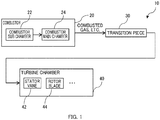
- Fig. 1 is a diagram illustrating an example of constituent components of a gas turbine provided at a thermal power plant or the like.
- a gas turbine 10 is made of a plurality of nickel-cobalt-based heat resistant alloys, for example.
- the gas turbine 10 includes a combustor 20 which includes a combustor sub chamber 22 and a combustor main chamber 24, mixes a fuel with compressed air, and combusts them, a transition piece 30 (transition piece) through which the combusted gas, water vapor, and the like generated in the combustor 20 flow, and a turbine chamber 40 which converts the thermal energy of the combusted gas and the like flowing in from the transition piece 30 into rotational energy.
- a transition piece 30 transition piece
- turbine chamber 40 which converts the thermal energy of the combusted gas and the like flowing in from the transition piece 30 into rotational energy.
- each of these constituent components is a precipitation-strengthened cast product obtained by performing precipitation strengthening on a metallic material mainly by aging heat treatment or the like.
- Fig. 2 is a diagram illustrating an example of the structure of a rotor blade 44.
- thermal stress is generated due to repetition of starting and stopping of the gas turbine 10, and a loss (thinning) tends to occur particularly at its tip portion 48.
- a loss thinning
- precipitation-strengthened cast product welding repair methods according to embodiments of the present disclosure will be described by taking welding repair of this loss as an example.
- Fig. 3 is a diagram illustrating an example of the procedure of a precipitation-strengthened cast product welding repair method in a first embodiment.
- a first weld layer formation step is carried out in which a first weld layer (build-up layer) is formed at a damaged portion (lost portion) formed at the tip portion 48 of the rotor blade 44 by performing micro TIG (Micro Tungsten Inert Gas) welding (s11).
- micro TIG Micro Tungsten Inert Gas
- Fig. 4 is a diagram explaining an example of the first weld layer formation step in the first embodiment.
- build-up welding is performed using a welding electrode 52 and a welding torch 57 such that a first weld layer 54 is formed on an exposed surface 55 (lost surface) of a lost portion 50 formed at the tip portion 48 of the rotor blade 44 so as to entirely cover the exposed surface 55 (s11).
- the first weld layer 54 may be a single weld layer or weld layers including two or more layers.
- the material (welding material) of the welding electrode 52 to be used to form the first weld layer 54 is an alloy containing a solid-solution-strengthened metal and having higher toughness than the metallic material of the rotor blade 44 being the base material.
- Examples of such an alloy include nickel-based alloys.
- the welding method in the first weld layer formation step is carried out as follows, for example. Firstly, as for the amount of heat input into the base material (the amount of thermal energy to be supplied by the welding torch 57 per unit time), inputting heat to the lost portion 50 with a welding current of a level used in common micro TIG welding generates large thermal stress in the lost portion 50, which leads to a possibility of fracture to (the tip portion 48 of) the rotor blade 44, which is the base material.
- the welding current therefore needs to be set lower.
- the welding current is preferably set at 50 A or lower. Note that in the micro TIG welding, the welding speed (the movement speed of the welding torch 57) is low. Thus, necessary heat can be evenly supplied to the entire first weld layer 54 although the welding current is low.
- the first weld layer 54 needs to have a certain thickness in order to prevent the occurrence of fracture or cracking (high-temperature fracture) of the repaired portion and a region around it during and after the repair. If, on the other hand, the thickness is too large, the operation time of the micro TIG welding becomes so long that the welding efficiency is impaired.
- the thickness of the first weld layer 54 is preferably set at about 1/3 of the depth of the lost portion 50 or less, for example. With this configuration, however, a sufficient weld layer cannot be formed if the lost portion 50 is shallow. In this case, it is preferable that the first weld layer 54 have a thickness of about several mm (at least 1 mm).
- a second weld layer formation step of forming a second weld layer is carried out by performing laser welding (laser cladding) (s13).
- laser welding laser cladding
- a common laser such as a carbon dioxide laser or a YAG laser, can be used, for example.
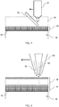
- Fig. 5 is a diagram explaining an example of the second weld layer formation step in the first embodiment.
- build-up welding is performed using alloy powder 56 made of the nickel-based alloy to be described next to form a second weld layer 58 on the first weld layer 54.
- the second weld layer 58 may be a single weld layer or weld layers including two or more layers.
- the alloy powder 56 is a nickel-based alloy containing a dual multi-phase nanostructure intermetallic compound alloy. Specifically, it is a nickel-based alloy in which an eutectoid structure with a D0 22 phase (Ni 3 Al) and an L1 2 phase (Ni 3 V) is formed on the nano-level by casting and solidifying nickel with aluminum and vanadium added thereto at predetermined ratios. Note that the ratios of aluminum and vanadium added and the ratios of other trace elements (such as boron) added are not particularly limited.
- the micro TIG welding used in the first weld layer formation step requires a certain amount of welding time since, due to its nature, the heat supply rate per unit time is lower than laser welding.
- the welding is performed in an efficient manner within a limit within which high-temperature fracture does not occur, in consideration of the time of the operation as a whole.
- the heat supply rate per unit time in the second weld layer formation step i.e., the output of a laser beam 62 from a laser apparatus 60
- the first weld layer formation step e.g., the output of the laser beam 62 is set at about several KW.
- the welding speed (the movement speed of the laser apparatus 60) is also preferably a speed higher than that in the first weld layer formation step (e.g., about 10 mm/sec).
- a weld layer of substantially the same shape as a shape corresponding to the lost portion 50 is formed to thereby repair the damaged portion formed at the tip portion 48 of the rotor blade 44.
- the first weld layer 54 is formed at the damaged portion of the base material of the precipitation-strengthened cast product by micro TIG welding (first weld layer formation step), and further the second weld layer 58 is formed on the first weld layer 54 by laser welding higher in heat supply rate than the micro TIG welding (second weld layer formation step).
- first weld layer formation step the second weld layer formation step.
- a solid-solution-strengthened welding material having higher toughness than the base material is used while, in the second weld layer formation step, a dual multi-phase nanostructure intermetallic compound is used as the welding material.
- This relaxes thermal stress applied to the repaired portion and thus prevents damaging of the repaired portion and a region around it during and after the repair (e.g., a reoccurrence of fracture or cracking of the repaired portion) while also rendering the base material tolerant to high temperature and enhancing the wear resistance and corrosion resistance.
- a precipitation-strengthened cast product can be repaired reliably and efficiently by appropriately combining a selection of welding materials and manners of heat supply.
- the current for the micro TIG welding in the first weld layer formation step is set at 50 A or lower. This can reliably prevent damaging of the repaired portion and a region around it during and after the repair (e.g., a reoccurrence of fracture or cracking of the repaired portion).
- the thickness of the first weld layer 54 is set at 1 mm or more and the thickness of the first weld layer 54 is set at 1/3 or less of the thickness of the entire weld layer. In this way, the welding operation can be completed reliably and quickly. For example, even when the damaged portion is large, the repair can be done within an appropriate time.
- the first weld layer 54 is formed so as to cover the exposed surface 55 of the damaged portion of the precipitation-strengthened cast product. This makes it possible to prevent a situation where a local deformation or damage occurs at the boundary between the damaged portion of the base material and the weld during and after the repair and the base material needs to be repaired again.
- Fig. 6 is a diagram illustrating an example of the procedure of a precipitation-strengthened cast product welding repair method in a second embodiment.
- a first weld layer formation step of forming a first weld layer 54 is similar to s11 of the first embodiment.
- the second weld layer 58 (build-up layer) is then formed on the first weld layer 54 by performing laser welding (laser cladding) using a nickel-based alloy containing a dual multi-phase nanostructure intermetallic compound alloy.
- laser welding is performed which is build-up welding using alloy powder made of an alloy of the same materials as the welding electrode 52 used in the first weld layer formation step (the materials do not have to be exactly the same as long as the compositional ratio of the constituent elements is substantially the same) to thereby form a second weld layer 58 made of substantially the same welding material as that in the first weld layer formation step on the first weld layer 54 (s12).
- a third weld layer (build-up layer) is formed in a similar manner to the first embodiment on the second weld layer 58 by performing laser welding (laser cladding) using the nickel-based alloy containing the dual multi-phase nanostructure intermetallic compound alloy.
- the second weld layer 58 and a third weld layer 59 may each be a single weld layer or weld layers including two or more layers.
- Fig. 7 is a diagram explaining an example of the second weld layer formation step and the third weld layer formation step in the second embodiment.
- the second weld layer 58 formed in the second weld layer formation step is made of an alloy of the same materials as the first weld layer 54 formed in the first weld layer formation step.
- the third weld layer 59 formed in the third weld layer formation step is made of the nickel-based alloy containing the dual multi-phase nanostructure intermetallic compound alloy.
- the second weld layer 58 and the third weld layer 59 are formed as above, weld layers of substantially the same shape as a shape corresponding to the lost portion 50 are formed to thereby repair the damaged portion formed at the tip portion 48 of the rotor blade 44.
- the thickness ratio of the second weld layer 58 and the third weld layer 59 is set as desired according to the mechanical strength and toughness which the base material is required to have, for example.
- the first weld layer 54 is formed at the damaged portion of the precipitation-strengthened cast product by micro TIG welding (first weld layer formation step)
- the second weld layer 58 is formed on the first weld layer 54 by laser welding higher in heat supply rate than the micro TIG welding (second weld layer formation step)
- the third weld layer 59 is formed on the second weld layer 58 by laser welding higher in heat supply rate than the micro TIG welding (third weld layer formation step).
- the amount of heat input per unit time is small but the welding speed is low, so that reliable welding is performed.
- the amount of heat input per unit time is large and the welding time is short.
- a solid-solution-strengthened welding material containing a solid-solution-strengthened alloy and having higher toughness than the base material is used while, in the third weld layer formation step, a dual multi-phase nanostructure intermetallic compound is used as the welding material.
- a cast product can be repaired reliably and efficiently by appropriately combining a selection of welding materials and manners of heat supply.
- the current for the micro TIG welding is set at 50 A or lower. This can reliably prevent damaging of the repaired portion and a region around it during and after the repair (e.g., a reoccurrence of fracture or cracking of the repaired portion).
- the thickness of the first weld layer 54 is set at 1 mm or more and the thickness of the first weld layer 54 is set at 1/3 or less of the thickness of the entire weld layer. In this way, the welding operation can be completed reliably and quickly. For example, even when the damaged portion is large, the repair can be done within an appropriate time.
- the first weld layer 54 is formed so as to cover the exposed surface of the damaged portion of the precipitation-strengthened cast product. This makes it possible to prevent a situation where a local deformation or damage occurs at the boundary between the damaged portion of the base material and the weld during and after the repair and the base material needs to be repaired again.
- Fig. 8 is a diagram illustrating an example of the procedure of a precipitation-strengthened cast product welding repair method in a third embodiment.
- laser welding is used for both a first weld layer 54 and a second weld layer 58 (s21, s23).
- Fig. 9 is a diagram explaining an example of a first weld layer formation step in the third embodiment.
- Fig. 10 is a diagram explaining an example of a second weld layer formation step in the third embodiment.
- the welding material to be used to form the first weld layer 54 is an alloy containing a solid-solution-strengthened metal and having higher toughness than the metallic material of the rotor blade 44 being the base material.
- the welding material to be used to form the second weld layer 58 is a nickel-based alloy containing a dual multi-phase nanostructure intermetallic compound alloy.
- the heat supply rate (the output of the laser beam 62) per unit time in the formation of the second weld layer 58 is set higher than that for the first weld layer 54
- the welding speed (the movement speed of the laser apparatus 60) in the formation of the second weld layer 58 is set higher than that for the first weld layer 54
- the rate of supply of the alloy powder 56 in the formation of the second weld layer 58 is set higher than that for the first weld layer 54.
- the output of the laser beam 62 is set at about 1 KW in the formation of the first weld layer 54 and is set about several times higher than that in the formation of the second weld layer 58.
- the welding speed in the formation of the second weld layer 58 is also set about several times higher than that in the formation of the first weld layer 54 (several mm/sec).
- the rate of supply of the alloy powder 56 in the formation of the second weld layer 58 is set several times higher than that in the formation of the first weld layer 54. Note that the thicknesses of the first weld layer 54 and the second weld layer 58 are similar to those in the first embodiment.
- weld layers of a shape corresponding to the lost portion 50 are formed to thereby repair the damaged portion formed at the tip portion 48 of the rotor blade 44.
- the first weld layer 54 is formed at the damaged portion of the base material of the precipitation-strengthened cast product by laser welding (first weld layer formation step), and further the second weld layer 58 is formed on the first weld layer 54 by laser welding using a dual multi-phase nanostructure intermetallic compound as the welding material and being higher in heat supply rate than the first laser welding (second weld layer formation step).
- first weld layer formation step the second weld layer formation step.
- the amount of heat input per unit time is large and the welding time is short.
- a solid-solution-strengthened welding material having higher toughness than the base material is used while, in the second weld layer formation step, a dual multi-phase nanostructure intermetallic compound is used as the welding material. This relaxes thermal stress applied to the repaired portion and thus prevents damaging of the repaired portion and a region around it during and after the repair (e.g., a reoccurrence of fracture or cracking of the repaired portion) while also rendering the base material tolerant to high temperature and enhancing the wear resistance and corrosion resistance.
- a precipitation-strengthened cast product can be repaired reliably and efficiently by appropriately combining a selection of welding materials and welding methods differing in the manner of heat supply.
- the thickness of the first weld layer 54 is set at 1 mm or more and the thickness of the first weld layer 54 is set at 1/3 or less of the thickness of the entire weld layer. In this way, the welding operation can be completed reliably and quickly. For example, even when the damaged portion is large, the repair can be done within an appropriate time.
- the first weld layer 54 is formed so as to cover the exposed surface of the damaged portion of the precipitation-strengthened cast product. This makes it possible to prevent a situation where a local deformation or damage occurs at the boundary between the damaged portion of the base material and the weld during and after the repair and the base material needs to be repaired again.
- the welding methods in the embodiments may be combined as appropriate or partly omitted.
- the welding repair methods according to the embodiments are applicable to welding repair of heat-resistant alloy members in general, including constituent components of the gas turbine 10 (combustor 20, transition piece 30, stator vanes 42, rotor blades 44).
Landscapes
- Engineering & Computer Science (AREA)
- Mechanical Engineering (AREA)
- Physics & Mathematics (AREA)
- Chemical & Material Sciences (AREA)
- Plasma & Fusion (AREA)
- Materials Engineering (AREA)
- Optics & Photonics (AREA)
- Manufacturing & Machinery (AREA)
- Metallurgy (AREA)
- Organic Chemistry (AREA)
- Composite Materials (AREA)
- Arc Welding In General (AREA)
- Laser Beam Processing (AREA)
- Powder Metallurgy (AREA)
Abstract
Description
- The present disclosure relates to a precipitation-strengthened cast product welding repair method.
- The high-temperature strength of cast products, such as the rotor blades, combustor, and transition piece of a turbine at a thermal power generation facility, a nuclear power generation facility, or the like, can be improved by using a precipitation-strengthened super heat resistant alloy (such as a nickel-based super heat resistant alloy) as their material. However, when these cast products are exposed to high-temperature and high-pressure conditions for a long period of time, their surfaces and the like are sometimes cracked or damaged due to thermal stress generated by repetition of starting and stopping of the turbine and the like. This case is handled by performing repair by TIG welding, laser welding, or the like at the power plant.
- In this respect, it is conceivable to enhance the effect of the repair by improving the material of the base material. For example, PTL 1 discloses a Ni3Al-based intermetallic compound made of Al at greater than 5 at% and 13 at%, V at 9.5 at% or greater and 17.4 at% or less, Nb at 0 at% or greater and 5 at% or less, B at 50 ppm by weight or greater and 1000 ppm by weight or less, and Ni as the balance excluding impurities, and having a dual multi-phase structure with a primary L12 phase and an (L12 + D022) eutectoid structure. Also, PTL 2 discloses a Ni-based intermetallic compound alloy containing B at 10 to 1000 ppm by weight relative to the total weight of a composition containing Ni as a main component and 2 to 9 atomic% Al, 10 to 17 atomic% V, 0.5 to 8 atomic% (Ta and/or W), 0 to 6 atomic% Nb, 0 to 6 atomic% Co, and 0 to 6 atomic% Cr which make up 100 at% in total, and having a dual multi-phase structure with a primary precipitate L12 phase and an (L12 + D022) eutectoid structure.
- PTL 3 discloses another repair method including removing a damaged portion of the base material of a gas turbine member or the like, forming an intermediate layer on the removal portion where the damaged portion has been removed, and performing build-up welding thereon to thereby repair the gas turbine member.
-
- [PTL 1] International Publication No.
2007/086185 - [PTL 2]
Japanese Patent Application Publication No. 2009-215649 - [PTL 3]
Japanese Patent Application Publication No. 2013-68085 - As it stands, however, welding operations as represented by PTL 3 are very complicated and still inefficient. For example, combustors and transition pieces need heat treatment after they are transported to factories, which requires time and cost since they are large-sized components. Also, in the case of rotor blades, laser welding or TIG welding is performed to handle the thinning of their tip portions, but cracking reoccurs in many cases, which leads to a poor yield.
- The present disclosure has been made in view of such circumstances, and an object thereof is to provide a precipitation-strengthened cast product welding repair method capable of reliably and efficiently repairing a precipitation-strengthened cast product.
- A first aspect of the present disclosure is a precipitation-strengthened cast product welding repair method being a method of repairing a damaged portion of a precipitation-strengthened cast product, the method comprising: a first weld layer formation step of forming a first weld layer on a surface of the damaged portion by micro TIG welding using a solid-solution-strengthened welding material having higher toughness than the cast product; and a second weld layer formation step of forming a second weld layer on the first weld layer by building up the second weld layer by laser welding using a dual multi-phase nanostructure intermetallic compound as a welding material and being higher in heat supply rate than the micro TIG welding.
- As described above, the first weld layer is formed at the damaged portion of the base material of the precipitation-strengthened cast product by micro TIG welding (first weld layer formation step), and further the second weld layer is formed on the first weld layer by laser welding higher in heat supply rate than the micro TIG welding (second weld layer formation step). In this way, in the formation of the first weld layer, which is the lower layer closer (or adjacent) to the base material, the amount of heat input per unit time is small but the welding speed is low, so that reliable welding is performed. In the formation of the second weld layer, which is the upper layer, the amount of heat input per unit time is large and the welding time is short. Further, in the first weld layer formation step, a solid-solution-strengthened welding material having higher toughness than the base material is used while, in the second weld layer formation step, a dual multi-phase nanostructure intermetallic compound is used as the welding material. This relaxes thermal stress applied to the repaired portion and thus prevents damaging of the repaired portion and a region around it during and after the repair (e.g., a reoccurrence of fracture or cracking of the repaired portion) while also rendering the base material tolerant to high temperature and enhancing the wear resistance and corrosion resistance.
- Thus, with the cast product welding repair method of the present disclosure, a precipitation-strengthened cast product can be repaired reliably and efficiently by appropriately combining a selection of welding materials and manners of heat supply.
- A second aspect of the present disclosure is a precipitation-strengthened cast product welding repair method being a method of repairing a damaged portion of a precipitation-strengthened cast product, the method comprising: a first weld layer formation step of forming a first weld layer on a surface of the damaged portion by micro TIG welding using a solid-solution-strengthened welding material having higher toughness than the cast product; a second weld layer formation step of forming a second weld layer on the first weld layer by laser welding using a same welding material as the first weld layer formation step and being higher in heat supply rate than the micro TIG welding; and a third weld layer formation step of forming a third weld layer on the second weld layer by building up the third weld layer by laser welding using a dual multi-phase nanostructure intermetallic compound as a welding material and being higher in heat supply rate than the micro TIG welding.
- As described above, the first weld layer is formed at the damaged portion of the precipitation-strengthened cast product by micro TIG welding (first weld layer formation step), the second weld layer is formed on the first weld layer by laser welding higher in heat supply rate than the micro TIG welding (second weld layer formation step), and additionally the third weld layer is formed on the second weld layer by laser welding higher in heat supply rate than the micro TIG welding (third weld layer formation step). In this way, in the formation of the first weld layer, which is the lower layer closest (or adjacent) to the base material, the amount of heat input per unit time is small but the welding speed is low, so that reliable welding is performed. In the formation of the second and third weld layer, which are the upper layers, the amount of heat input per unit time is large and the welding time is short. Further, in the first weld layer formation step and the second weld layer formation step, a solid-solution-strengthened welding material containing a solid-solution-strengthened alloy and having higher toughness than the base material is used while, in the third weld layer formation step, a dual multi-phase nanostructure intermetallic compound is used as the welding material. This relaxes thermal stress applied to the repaired portion and thus prevents damaging of the repaired portion and a region around it during and after the repair (e.g., a reoccurrence of fracture or cracking of the repaired portion) while also rendering the base material tolerant to high temperature and enhancing the wear resistance and corrosion resistance.
- Thus, with the cast product welding repair method of the present disclosure, a cast product can be repaired reliably and efficiently by appropriately combining a selection of welding materials and manners of heat supply.
- A third aspect of the present disclosure is a precipitation-strengthened cast product welding repair method being a method of repairing a damaged portion of a precipitation-strengthened cast product, the method comprising: a first weld layer formation step of forming a first weld layer on a surface of the damaged portion by laser welding using a solid-solution-strengthened welding material having higher toughness than the cast product; and a second weld layer formation step of forming a second weld layer on the first weld layer by building up the second weld layer by laser welding using a dual multi-phase nanostructure intermetallic compound as a welding material and being higher in heat supply rate than the laser welding.
- As described above, the first weld layer is formed at the damaged portion of the base material of the precipitation-strengthened cast product by laser welding (first weld layer formation step), and further the second weld layer is formed on the first weld layer by laser welding using a dual multi-phase nanostructure intermetallic compound as the welding material and being higher in heat supply rate than the first laser welding (second weld layer formation step) . In this way, in the formation of the first weld layer, which is the lower layer closer (or adjacent) to the base material, the amount of heat input per unit time is small but the welding speed is low, so that reliable welding is performed. In the formation of the second weld layer, which is the upper layer, the amount of heat input per unit time is large and the welding time is short. Further, in the first weld layer formation step, a solid-solution-strengthened welding material having higher toughness than the base material is used while, in the second weld layer formation step, a dual multi-phase nanostructure intermetallic compound is used as the welding material. This relaxes thermal stress applied to the repaired portion and thus prevents damaging of the repaired portion and a region around it during and after the repair (e.g., a reoccurrence of fracture or cracking of the repaired portion) while also rendering the base material tolerant to high temperature and enhancing the wear resistance and corrosion resistance.
- Thus, with the cast product welding repair method of the present disclosure, a precipitation-strengthened cast product can be repaired reliably and efficiently by appropriately combining a selection of welding materials and welding methods differing in the manner of heat supply.
- In the first and second aspects, for example, a current for the micro TIG welding in the first weld layer formation step is set at 50 A or lower.
- As described above, the current for the micro TIG welding is set at 50 A or lower. This can reliably prevent damaging of the repaired portion and a region around it during and after the repair (e.g., a reoccurrence of fracture or cracking of the repaired portion).
- In the first to third aspects, for example, a thickness of the first weld layer is set at 1 mm or more and 1/3 or less of a total thickness of the weld layers.
- As described above, the thickness of the first weld layer is set at 1 mm or more and the thickness of the first weld layer is set at 1/3 or less of the thickness of the entire weld layer. In this way, the welding operation can be completed reliably and quickly. For example, even when the damaged portion is large, the repair can be done within an appropriate time.
- Note that, in the first to third aspects, in the first weld layer formation step, the first weld layer is formed so as to cover an exposed surface of the damaged portion.
- The first weld layer is formed so as to cover the exposed surface of the damaged portion of the precipitation-strengthened cast product. This makes it possible to prevent a situation where a local deformation or damage occurs at the boundary between the damaged portion of the base material and the weld during and after the repair and the base material needs to be repaired again.
- According to the present disclosure, it is possible to reliably and efficiently repair a precipitation-strengthened cast product.
-
- [
Fig. 1] Fig. 1 is a diagram illustrating an example of constituent components of a gas turbine provided at a thermal power plant or the like. - [
Fig. 2] Fig. 2 is a diagram illustrating an example of the structure of arotor blade 44. - [
Fig. 3] Fig. 3 is a diagram illustrating an example of the procedure of a precipitation-strengthened cast product welding repair method in a first embodiment. - [
Fig. 4] Fig. 4 is a diagram explaining an example of a first weld layer formation step in the first embodiment. - [
Fig. 5] Fig. 5 is a diagram explaining an example of a second weld layer formation step in the first embodiment. - [
Fig. 6] Fig. 6 is a diagram illustrating an example of the procedure of a precipitation-strengthened cast product welding repair method in a second embodiment. - [
Fig. 7] Fig. 7 is a diagram explaining an example of a second weld layer formation step and a third weld layer formation step in the second embodiment. - [
Fig. 8] Fig. 8 is a diagram illustrating an example of the procedure of a precipitation-strengthened cast product welding repair method in a third embodiment. - [
Fig. 9] Fig. 9 is a diagram explaining an example of a first weld layer formation step in the third embodiment. - [
Fig. 10] Fig. 10 is a diagram explaining an example of a second weld layer formation step in the third embodiment. - Embodiments of the present disclosure will be described with reference to the drawings.
-
Fig. 1 is a diagram illustrating an example of constituent components of a gas turbine provided at a thermal power plant or the like. Agas turbine 10 is made of a plurality of nickel-cobalt-based heat resistant alloys, for example. Specifically, thegas turbine 10 includes acombustor 20 which includes acombustor sub chamber 22 and a combustormain chamber 24, mixes a fuel with compressed air, and combusts them, a transition piece 30 (transition piece) through which the combusted gas, water vapor, and the like generated in thecombustor 20 flow, and aturbine chamber 40 which converts the thermal energy of the combusted gas and the like flowing in from thetransition piece 30 into rotational energy. In theturbine chamber 40, a plurality ofstator vanes 42 that regulate the flow of the combusted gas and the like and a plurality ofrotor blades 44 that compress and convert the combusted gas and the like into rotational energy are arranged alternately. Note that in the present embodiment, each of these constituent components is a precipitation-strengthened cast product obtained by performing precipitation strengthening on a metallic material mainly by aging heat treatment or the like. - Here,
Fig. 2 is a diagram illustrating an example of the structure of arotor blade 44. In eachrotor blade 44, thermal stress is generated due to repetition of starting and stopping of thegas turbine 10, and a loss (thinning) tends to occur particularly at itstip portion 48. Thus, precipitation-strengthened cast product welding repair methods according to embodiments of the present disclosure will be described by taking welding repair of this loss as an example. -
Fig. 3 is a diagram illustrating an example of the procedure of a precipitation-strengthened cast product welding repair method in a first embodiment. Firstly, a first weld layer formation step is carried out in which a first weld layer (build-up layer) is formed at a damaged portion (lost portion) formed at thetip portion 48 of therotor blade 44 by performing micro TIG (Micro Tungsten Inert Gas) welding (s11). - Here,
Fig. 4 is a diagram explaining an example of the first weld layer formation step in the first embodiment. In this first weld layer formation step, build-up welding is performed using awelding electrode 52 and awelding torch 57 such that afirst weld layer 54 is formed on an exposed surface 55 (lost surface) of a lostportion 50 formed at thetip portion 48 of therotor blade 44 so as to entirely cover the exposed surface 55 (s11). Thefirst weld layer 54 may be a single weld layer or weld layers including two or more layers. - The material (welding material) of the
welding electrode 52 to be used to form thefirst weld layer 54 is an alloy containing a solid-solution-strengthened metal and having higher toughness than the metallic material of therotor blade 44 being the base material. Examples of such an alloy include nickel-based alloys. - More specifically, the welding method in the first weld layer formation step is carried out as follows, for example. Firstly, as for the amount of heat input into the base material (the amount of thermal energy to be supplied by the
welding torch 57 per unit time), inputting heat to the lostportion 50 with a welding current of a level used in common micro TIG welding generates large thermal stress in the lostportion 50, which leads to a possibility of fracture to (thetip portion 48 of) therotor blade 44, which is the base material. The welding current therefore needs to be set lower. For example, the welding current is preferably set at 50 A or lower. Note that in the micro TIG welding, the welding speed (the movement speed of the welding torch 57) is low. Thus, necessary heat can be evenly supplied to the entirefirst weld layer 54 although the welding current is low. - Incidentally, the
first weld layer 54 needs to have a certain thickness in order to prevent the occurrence of fracture or cracking (high-temperature fracture) of the repaired portion and a region around it during and after the repair. If, on the other hand, the thickness is too large, the operation time of the micro TIG welding becomes so long that the welding efficiency is impaired. Considering the above, the thickness of thefirst weld layer 54 is preferably set at about 1/3 of the depth of the lostportion 50 or less, for example. With this configuration, however, a sufficient weld layer cannot be formed if the lostportion 50 is shallow. In this case, it is preferable that thefirst weld layer 54 have a thickness of about several mm (at least 1 mm). - As illustrated in
Fig. 3 , a second weld layer formation step of forming a second weld layer (build-up layer) is carried out by performing laser welding (laser cladding) (s13). Note that in this laser welding, a common laser, such as a carbon dioxide laser or a YAG laser, can be used, for example. -
Fig. 5 is a diagram explaining an example of the second weld layer formation step in the first embodiment. In the second weld layer formation step, build-up welding is performed usingalloy powder 56 made of the nickel-based alloy to be described next to form asecond weld layer 58 on thefirst weld layer 54. As with thefirst weld layer 54, thesecond weld layer 58 may be a single weld layer or weld layers including two or more layers. - Here, the
alloy powder 56 is a nickel-based alloy containing a dual multi-phase nanostructure intermetallic compound alloy. Specifically, it is a nickel-based alloy in which an eutectoid structure with a D022 phase (Ni3Al) and an L12 phase (Ni3V) is formed on the nano-level by casting and solidifying nickel with aluminum and vanadium added thereto at predetermined ratios. Note that the ratios of aluminum and vanadium added and the ratios of other trace elements (such as boron) added are not particularly limited. - Here, the micro TIG welding used in the first weld layer formation step requires a certain amount of welding time since, due to its nature, the heat supply rate per unit time is lower than laser welding. Thus, in the second weld layer formation step, the welding is performed in an efficient manner within a limit within which high-temperature fracture does not occur, in consideration of the time of the operation as a whole.
- Specifically, the heat supply rate per unit time in the second weld layer formation step, i.e., the output of a
laser beam 62 from alaser apparatus 60, is preferably higher than at least that in the first weld layer formation step (e.g., the output of thelaser beam 62 is set at about several KW). Moreover, the welding speed (the movement speed of the laser apparatus 60) is also preferably a speed higher than that in the first weld layer formation step (e.g., about 10 mm/sec). - By forming the
second weld layer 58 by a welding method as above, a weld layer of substantially the same shape as a shape corresponding to the lostportion 50 is formed to thereby repair the damaged portion formed at thetip portion 48 of therotor blade 44. - As described above, in the welding repair method in the present embodiment, the
first weld layer 54 is formed at the damaged portion of the base material of the precipitation-strengthened cast product by micro TIG welding (first weld layer formation step), and further thesecond weld layer 58 is formed on thefirst weld layer 54 by laser welding higher in heat supply rate than the micro TIG welding (second weld layer formation step). In this way, in the formation of thefirst weld layer 54, which is the lower layer closer (or adjacent) to the base material, the amount of heat input per unit time is small but the welding speed is low, so that reliable welding is performed. In the formation of thesecond weld layer 58, which is the upper layer, the amount of heat input per unit time is large and the welding time is short. Further, in the first weld layer formation step, a solid-solution-strengthened welding material having higher toughness than the base material is used while, in the second weld layer formation step, a dual multi-phase nanostructure intermetallic compound is used as the welding material. This relaxes thermal stress applied to the repaired portion and thus prevents damaging of the repaired portion and a region around it during and after the repair (e.g., a reoccurrence of fracture or cracking of the repaired portion) while also rendering the base material tolerant to high temperature and enhancing the wear resistance and corrosion resistance. - Thus, with the precipitation-strengthened cast product welding repair method in the present embodiment, a precipitation-strengthened cast product can be repaired reliably and efficiently by appropriately combining a selection of welding materials and manners of heat supply.
- Also, in the precipitation-strengthened cast product welding repair method in the present embodiment, the current for the micro TIG welding in the first weld layer formation step is set at 50 A or lower. This can reliably prevent damaging of the repaired portion and a region around it during and after the repair (e.g., a reoccurrence of fracture or cracking of the repaired portion).
- Also, in the precipitation-strengthened cast product welding repair method in the present embodiment, the thickness of the
first weld layer 54 is set at 1 mm or more and the thickness of thefirst weld layer 54 is set at 1/3 or less of the thickness of the entire weld layer. In this way, the welding operation can be completed reliably and quickly. For example, even when the damaged portion is large, the repair can be done within an appropriate time. - Also, in the precipitation-strengthened cast product welding repair method in the present embodiment, the
first weld layer 54 is formed so as to cover the exposedsurface 55 of the damaged portion of the precipitation-strengthened cast product. This makes it possible to prevent a situation where a local deformation or damage occurs at the boundary between the damaged portion of the base material and the weld during and after the repair and the base material needs to be repaired again. -
Fig. 6 is a diagram illustrating an example of the procedure of a precipitation-strengthened cast product welding repair method in a second embodiment. A first weld layer formation step of forming afirst weld layer 54 is similar to s11 of the first embodiment. - In the first embodiment, the second weld layer 58 (build-up layer) is then formed on the
first weld layer 54 by performing laser welding (laser cladding) using a nickel-based alloy containing a dual multi-phase nanostructure intermetallic compound alloy. - In the present embodiment, however, before the formation of the build-up layer with the dual multi-phase nanostructure intermetallic compound alloy, laser welding is performed which is build-up welding using alloy powder made of an alloy of the same materials as the
welding electrode 52 used in the first weld layer formation step (the materials do not have to be exactly the same as long as the compositional ratio of the constituent elements is substantially the same) to thereby form asecond weld layer 58 made of substantially the same welding material as that in the first weld layer formation step on the first weld layer 54 (s12). - Then , a third weld layer (build-up layer) is formed in a similar manner to the first embodiment on the
second weld layer 58 by performing laser welding (laser cladding) using the nickel-based alloy containing the dual multi-phase nanostructure intermetallic compound alloy. - As with the
first weld layer 54, thesecond weld layer 58 and athird weld layer 59 may each be a single weld layer or weld layers including two or more layers. -
Fig. 7 is a diagram explaining an example of the second weld layer formation step and the third weld layer formation step in the second embodiment. Thesecond weld layer 58 formed in the second weld layer formation step is made of an alloy of the same materials as thefirst weld layer 54 formed in the first weld layer formation step. Unlike thefirst weld layer 54 and thesecond weld layer 58, thethird weld layer 59 formed in the third weld layer formation step is made of the nickel-based alloy containing the dual multi-phase nanostructure intermetallic compound alloy. - By forming the
second weld layer 58 and thethird weld layer 59 as above, weld layers of substantially the same shape as a shape corresponding to the lostportion 50 are formed to thereby repair the damaged portion formed at thetip portion 48 of therotor blade 44. Note that the thickness ratio of thesecond weld layer 58 and thethird weld layer 59 is set as desired according to the mechanical strength and toughness which the base material is required to have, for example. - As described above, in the precipitation-strengthened cast product welding repair method in the present embodiment, the
first weld layer 54 is formed at the damaged portion of the precipitation-strengthened cast product by micro TIG welding (first weld layer formation step), thesecond weld layer 58 is formed on thefirst weld layer 54 by laser welding higher in heat supply rate than the micro TIG welding (second weld layer formation step), and additionally thethird weld layer 59 is formed on thesecond weld layer 58 by laser welding higher in heat supply rate than the micro TIG welding (third weld layer formation step). In this way, in the formation of thefirst weld layer 54, which is the lower layer closest (or adjacent) to the base material, the amount of heat input per unit time is small but the welding speed is low, so that reliable welding is performed. In the formation of the second and third weld layers 58 and 59, which are the upper layers, the amount of heat input per unit time is large and the welding time is short. Further, in the first weld layer formation step and the second weld layer formation step, a solid-solution-strengthened welding material containing a solid-solution-strengthened alloy and having higher toughness than the base material is used while, in the third weld layer formation step, a dual multi-phase nanostructure intermetallic compound is used as the welding material. This relaxes thermal stress applied to the repaired portion and thus prevents damaging of the repaired portion and a region around it during and after the repair (e.g., a reoccurrence of fracture or cracking of the repaired portion) while also rendering the base material tolerant to high temperature and enhancing the wear resistance and corrosion resistance. - Thus, with the precipitation-strengthened cast product welding repair method in the present embodiment, a cast product can be repaired reliably and efficiently by appropriately combining a selection of welding materials and manners of heat supply.
- Also, in the precipitation-strengthened cast product welding repair method in the present embodiment, the current for the micro TIG welding is set at 50 A or lower. This can reliably prevent damaging of the repaired portion and a region around it during and after the repair (e.g., a reoccurrence of fracture or cracking of the repaired portion).
- Also, in the precipitation-strengthened cast product welding repair method in the present embodiment, the thickness of the
first weld layer 54 is set at 1 mm or more and the thickness of thefirst weld layer 54 is set at 1/3 or less of the thickness of the entire weld layer. In this way, the welding operation can be completed reliably and quickly. For example, even when the damaged portion is large, the repair can be done within an appropriate time. - Also, in the precipitation-strengthened cast product welding repair method in the present embodiment, the
first weld layer 54 is formed so as to cover the exposed surface of the damaged portion of the precipitation-strengthened cast product. This makes it possible to prevent a situation where a local deformation or damage occurs at the boundary between the damaged portion of the base material and the weld during and after the repair and the base material needs to be repaired again. -
Fig. 8 is a diagram illustrating an example of the procedure of a precipitation-strengthened cast product welding repair method in a third embodiment. In the present embodiment, unlike the first embodiment, laser welding is used for both afirst weld layer 54 and a second weld layer 58 (s21, s23). -
Fig. 9 is a diagram explaining an example of a first weld layer formation step in the third embodiment. Also,Fig. 10 is a diagram explaining an example of a second weld layer formation step in the third embodiment. - As with the first embodiment, the welding material to be used to form the
first weld layer 54 is an alloy containing a solid-solution-strengthened metal and having higher toughness than the metallic material of therotor blade 44 being the base material. Also, as with the first embodiment, the welding material to be used to form thesecond weld layer 58 is a nickel-based alloy containing a dual multi-phase nanostructure intermetallic compound alloy. - As for a specific welding method, the heat supply rate (the output of the laser beam 62) per unit time in the formation of the
second weld layer 58 is set higher than that for thefirst weld layer 54, and the welding speed (the movement speed of the laser apparatus 60) in the formation of thesecond weld layer 58 is set higher than that for thefirst weld layer 54. Also, the rate of supply of thealloy powder 56 in the formation of thesecond weld layer 58 is set higher than that for thefirst weld layer 54. - For example, the output of the
laser beam 62 is set at about 1 KW in the formation of thefirst weld layer 54 and is set about several times higher than that in the formation of thesecond weld layer 58. Further, the welding speed in the formation of thesecond weld layer 58 is also set about several times higher than that in the formation of the first weld layer 54 (several mm/sec). Furthermore, the rate of supply of thealloy powder 56 in the formation of thesecond weld layer 58 is set several times higher than that in the formation of thefirst weld layer 54. Note that the thicknesses of thefirst weld layer 54 and thesecond weld layer 58 are similar to those in the first embodiment. - By forming the
first weld layer 54 and thesecond weld layer 58 by a welding method as above, weld layers of a shape corresponding to the lostportion 50 are formed to thereby repair the damaged portion formed at thetip portion 48 of therotor blade 44. - As described above, in the precipitation-strengthened cast product welding repair method in the present embodiment, the
first weld layer 54 is formed at the damaged portion of the base material of the precipitation-strengthened cast product by laser welding (first weld layer formation step), and further thesecond weld layer 58 is formed on thefirst weld layer 54 by laser welding using a dual multi-phase nanostructure intermetallic compound as the welding material and being higher in heat supply rate than the first laser welding (second weld layer formation step). In this way, in the formation of thefirst weld layer 54, which is the lower layer closer (or adjacent) to the base material, the amount of heat input per unit time is small but the welding speed is low, so that reliable welding is performed. In the formation of thesecond weld layer 58, which is the upper layer, the amount of heat input per unit time is large and the welding time is short. Further, in the first weld layer formation step, a solid-solution-strengthened welding material having higher toughness than the base material is used while, in the second weld layer formation step, a dual multi-phase nanostructure intermetallic compound is used as the welding material. This relaxes thermal stress applied to the repaired portion and thus prevents damaging of the repaired portion and a region around it during and after the repair (e.g., a reoccurrence of fracture or cracking of the repaired portion) while also rendering the base material tolerant to high temperature and enhancing the wear resistance and corrosion resistance. - Thus, with the precipitation-strengthened cast product welding repair method of the present disclosure, a precipitation-strengthened cast product can be repaired reliably and efficiently by appropriately combining a selection of welding materials and welding methods differing in the manner of heat supply.
- Also, in the precipitation-strengthened cast product welding repair method in the present embodiment, the thickness of the
first weld layer 54 is set at 1 mm or more and the thickness of thefirst weld layer 54 is set at 1/3 or less of the thickness of the entire weld layer. In this way, the welding operation can be completed reliably and quickly. For example, even when the damaged portion is large, the repair can be done within an appropriate time. - Also, in the precipitation-strengthened cast product welding repair method in the present embodiment, the
first weld layer 54 is formed so as to cover the exposed surface of the damaged portion of the precipitation-strengthened cast product. This makes it possible to prevent a situation where a local deformation or damage occurs at the boundary between the damaged portion of the base material and the weld during and after the repair and the base material needs to be repaired again. - Embodiments of the present disclosure described above are simply to facilitate understanding of the present disclosure and are not in any way to be construed as limiting the present disclosure. The present disclosure may variously be changed or altered without departing from its essential features and encompass equivalents thereof.
- For example, the welding methods in the embodiments may be combined as appropriate or partly omitted.
- Also, in the embodiments, methods of repairing damage of the
tip portion 48 of therotor blade 44 by welding have been described. However, the welding repair methods according to the embodiments are applicable to welding repair of heat-resistant alloy members in general, including constituent components of the gas turbine 10 (combustor 20,transition piece 30,stator vanes 42, rotor blades 44). -
- 10
- Gas turbine
- 20
- Combustor
- 22
- Combustor sub chamber
- 24
- Combustor main chamber
- 30
- Transition piece
- 40
- Turbine chamber
- 42
- Stator vane
- 44
- Rotor blade
- 48
- Tip portion
- 50
- Lost portion
- 52
- Welding electrode
- 54
- First weld layer
- 55
- Exposed surface
- 56
- Powder
- 57
- Welding torch
- 58
- Second weld layer
- 59
- Third weld layer
- 60
- Laser apparatus
- 62
- Laser beam
Claims (6)
- A precipitation-strengthened cast product welding repair method being a method of repairing a damaged portion of a precipitation-strengthened cast product, the method comprising:a first weld layer formation step of forming a first weld layer on a surface of the damaged portion by micro TIG welding using a solid-solution-strengthened welding material having higher toughness than the cast product; anda second weld layer formation step of forming a second weld layer on the first weld layer by building up the second weld layer by laser welding using a dual multi-phase nanostructure intermetallic compound as a welding material and being higher in heat supply rate than the micro TIG welding.
- A precipitation-strengthened cast product welding repair method being a method of repairing a damaged portion of a precipitation-strengthened cast product, the method comprising:a first weld layer formation step of forming a first weld layer on a surface of the damaged portion by micro TIG welding using a solid-solution-strengthened welding material having higher toughness than the cast product;a second weld layer formation step of forming a second weld layer on the first weld layer by laser welding using a same welding material as the first weld layer formation step and being higher in heat supply rate than the micro TIG welding; anda third weld layer formation step of forming a third weld layer on the second weld layer by building up the third weld layer by laser welding using a dual multi-phase nanostructure intermetallic compound as a welding material and being higher in heat supply rate than the micro TIG welding.
- A precipitation-strengthened cast product welding repair method being a method of repairing a damaged portion of a precipitation-strengthened cast product, the method comprising:a first weld layer formation step of forming a first weld layer on a surface of the damaged portion by laser welding using a solid-solution-strengthened welding material having higher toughness than the cast product; anda second weld layer formation step of forming a second weld layer on the first weld layer by building up the second weld layer by laser welding using a dual multi-phase nanostructure intermetallic compound as a welding material and being higher in heat supply rate than the laser welding.
- The precipitation-strengthened cast product welding repair method according to claim 1 or 2, wherein a current for the micro TIG welding in the first weld layer formation step is set at 50 A or lower.
- The precipitation-strengthened cast product welding repair method according to any one of claims 1 to 3, wherein a thickness of the first weld layer is set at 1 mm or more and 1/3 or less of a total thickness of the weld layers.
- The precipitation-strengthened cast product welding repair method according to any one of claims 1 to 3, wherein in the first weld layer formation step, the first weld layer is formed so as to cover an exposed surface of the damaged portion.
Applications Claiming Priority (1)
| Application Number | Priority Date | Filing Date | Title |
|---|---|---|---|
| PCT/JP2019/007007 WO2020174523A1 (en) | 2019-02-25 | 2019-02-25 | Welding repair method for precipitation-strengthened cast product |
Publications (2)
| Publication Number | Publication Date |
|---|---|
| EP3932602A1 true EP3932602A1 (en) | 2022-01-05 |
| EP3932602A4 EP3932602A4 (en) | 2022-05-11 |
Family
ID=69412092
Family Applications (1)
| Application Number | Title | Priority Date | Filing Date |
|---|---|---|---|
| EP19917077.0A Withdrawn EP3932602A4 (en) | 2019-02-25 | 2019-02-25 | Welding repair method for precipitation-strengthened cast product |
Country Status (4)
| Country | Link |
|---|---|
| US (1) | US20220143759A1 (en) |
| EP (1) | EP3932602A4 (en) |
| JP (1) | JP6642780B1 (en) |
| WO (1) | WO2020174523A1 (en) |
Families Citing this family (3)
| Publication number | Priority date | Publication date | Assignee | Title |
|---|---|---|---|---|
| CN113458605A (en) * | 2021-07-12 | 2021-10-01 | 南京航空航天大学 | Device and method based on laser-MIG composite additive repair |
| US20240399452A1 (en) * | 2023-05-31 | 2024-12-05 | Raytheon Technologies Corporation | Hybrid additive manufacturing repair method |
| JP7514377B1 (en) | 2023-12-26 | 2024-07-10 | Dmg森精機株式会社 | Manufacturing method of additionally processed parts |
Family Cites Families (12)
| Publication number | Priority date | Publication date | Assignee | Title |
|---|---|---|---|---|
| US6364971B1 (en) * | 2000-01-20 | 2002-04-02 | Electric Power Research Institute | Apparatus and method of repairing turbine blades |
| GB2447222B (en) | 2006-01-30 | 2011-04-13 | Univ Osaka Prefect Public Corp | Ni3Al-based intermetallic compound with dual multi-phase microstructure, production method thereof, and heat-resistant structural material |
| US8561298B2 (en) * | 2007-03-01 | 2013-10-22 | Siemens Energy, Inc. | Superalloy component welding at ambient temperature |
| JP4417977B2 (en) * | 2007-04-25 | 2010-02-17 | 株式会社日立製作所 | Gas turbine blade and method for manufacturing the same |
| JP5162492B2 (en) | 2008-02-15 | 2013-03-13 | 公立大学法人大阪府立大学 | Ni-based intermetallic alloy with high hardness |
| EP2475495A1 (en) * | 2009-09-10 | 2012-07-18 | Sumitomo Chemical Company, Limited | Process for repairing pit and process for repairing metal member |
| JP2011136344A (en) * | 2009-12-25 | 2011-07-14 | Mitsubishi Heavy Ind Ltd | Method of repairing gas turbine member and the gas turbine member |
| JP2013068085A (en) | 2011-09-20 | 2013-04-18 | Toshiba Corp | Method for repairing gas turbine moving blade with squealer |
| EP2872286B1 (en) * | 2012-07-12 | 2018-09-19 | Ansaldo Energia IP UK Limited | Method for repairing a single crystal turbine blade |
| KR101677317B1 (en) * | 2013-07-03 | 2016-11-17 | 주식회사 포스코 | Method for manufacturing electrical steel sheet laminated core for reducing core loss and increasing strength and laminated core produced by the same |
| JP2017190688A (en) * | 2016-04-12 | 2017-10-19 | 株式会社東芝 | Turbine member, axial flow turbine, and method of manufacturing turbine member |
| US11135677B2 (en) * | 2018-03-06 | 2021-10-05 | General Electric Company | Laser welding of component |
-
2019
- 2019-02-25 US US17/433,498 patent/US20220143759A1/en not_active Abandoned
- 2019-02-25 EP EP19917077.0A patent/EP3932602A4/en not_active Withdrawn
- 2019-02-25 WO PCT/JP2019/007007 patent/WO2020174523A1/en not_active Ceased
- 2019-02-25 JP JP2019549496A patent/JP6642780B1/en active Active
Also Published As
| Publication number | Publication date |
|---|---|
| US20220143759A1 (en) | 2022-05-12 |
| JPWO2020174523A1 (en) | 2021-03-11 |
| WO2020174523A1 (en) | 2020-09-03 |
| JP6642780B1 (en) | 2020-02-12 |
| EP3932602A4 (en) | 2022-05-11 |
Similar Documents
| Publication | Publication Date | Title |
|---|---|---|
| JP7575871B2 (en) | High gamma prime nickel-base superalloys, their uses and methods for making turbine engine components - Patents.com | |
| CN106563929B (en) | Repair and manufacture the method and turbine engine components of turbine engine components | |
| US7547188B2 (en) | Ni-based alloy member, method of producing the alloy member, turbine engine part, welding material, and method of producing the welding material | |
| EP1179383B1 (en) | Shimmed electron beam welding process | |
| CN106170368B (en) | Structure for superalloy materials is brazed | |
| González et al. | Microstructural response to heat affected zone cracking of prewelding heat-treated Inconel 939 superalloy | |
| JP2020070487A (en) | High gamma prime nickel based superalloy, its use, and method of manufacturing turbine engine components | |
| EP2298489A1 (en) | Superalloy composition and method of forming a turbine engine component | |
| JP5537587B2 (en) | Ni-base alloy welding material and welding wire, welding rod and welding powder using the same | |
| US20220143759A1 (en) | Precipitation-strengthened cast product welding repair method | |
| JP5785376B2 (en) | Overlay welding method | |
| US20180257181A1 (en) | Method of cladding and fusion welding of superalloys | |
| JP2011136344A (en) | Method of repairing gas turbine member and the gas turbine member | |
| JP2013252561A (en) | Repaired superalloy component and method for repairing superalloy component | |
| JP2018171646A (en) | Weld filler and method of welding | |
| WO2022251781A2 (en) | A nickel based superalloy weld filler | |
| JP5599542B2 (en) | Heat resistant alloy and articles manufactured and repaired using the same | |
| CN108798805A (en) | Handle the method for turbine baffle and processed turbine baffle | |
| US20140099516A1 (en) | Brazed articles and methods of making the same | |
| WO2012135093A2 (en) | Nickel-base weld materials, processes of using, and components formed therewith | |
| EP3932603A1 (en) | Welding repair method for precipitation-strengthened cast product | |
| JP5439196B2 (en) | Damage repair method for high temperature parts of gas turbine | |
| US11039507B2 (en) | Method of brazing a treatment area of a load-bearing component | |
| JP2013148061A (en) | Method for repairing gas turbine moving blade with squealer | |
| Chan et al. | Advanced Tip Repair of Single Crystal HPT Blades With LW3 and LW4280 Welding Materials |
Legal Events
| Date | Code | Title | Description |
|---|---|---|---|
| STAA | Information on the status of an ep patent application or granted ep patent |
Free format text: STATUS: THE INTERNATIONAL PUBLICATION HAS BEEN MADE |
|
| PUAI | Public reference made under article 153(3) epc to a published international application that has entered the european phase |
Free format text: ORIGINAL CODE: 0009012 |
|
| STAA | Information on the status of an ep patent application or granted ep patent |
Free format text: STATUS: REQUEST FOR EXAMINATION WAS MADE |
|
| 17P | Request for examination filed |
Effective date: 20210923 |
|
| AK | Designated contracting states |
Kind code of ref document: A1 Designated state(s): AL AT BE BG CH CY CZ DE DK EE ES FI FR GB GR HR HU IE IS IT LI LT LU LV MC MK MT NL NO PL PT RO RS SE SI SK SM TR |
|
| A4 | Supplementary search report drawn up and despatched |
Effective date: 20220408 |
|
| RIC1 | Information provided on ipc code assigned before grant |
Ipc: B23K 103/18 20060101ALN20220404BHEP Ipc: B23K 101/00 20060101ALN20220404BHEP Ipc: B22F 3/115 20060101ALI20220404BHEP Ipc: B22F 3/105 20060101ALI20220404BHEP Ipc: B23K 26/00 20140101ALI20220404BHEP Ipc: B23K 9/173 20060101ALI20220404BHEP Ipc: B23K 9/167 20060101ALI20220404BHEP Ipc: C22C 19/03 20060101ALI20220404BHEP Ipc: B23K 31/00 20060101ALI20220404BHEP Ipc: B23K 26/34 20140101ALI20220404BHEP Ipc: B23K 9/04 20060101AFI20220404BHEP |
|
| DAV | Request for validation of the european patent (deleted) | ||
| DAX | Request for extension of the european patent (deleted) | ||
| GRAP | Despatch of communication of intention to grant a patent |
Free format text: ORIGINAL CODE: EPIDOSNIGR1 |
|
| STAA | Information on the status of an ep patent application or granted ep patent |
Free format text: STATUS: GRANT OF PATENT IS INTENDED |
|
| RIC1 | Information provided on ipc code assigned before grant |
Ipc: B23K 103/18 20060101ALN20221104BHEP Ipc: B23K 101/00 20060101ALN20221104BHEP Ipc: B22F 3/115 20060101ALI20221104BHEP Ipc: B22F 3/105 20060101ALI20221104BHEP Ipc: B23K 26/00 20140101ALI20221104BHEP Ipc: B23K 9/173 20060101ALI20221104BHEP Ipc: B23K 9/167 20060101ALI20221104BHEP Ipc: C22C 19/03 20060101ALI20221104BHEP Ipc: B23K 31/00 20060101ALI20221104BHEP Ipc: B23K 26/34 20140101ALI20221104BHEP Ipc: B23K 9/04 20060101AFI20221104BHEP |
|
| INTG | Intention to grant announced |
Effective date: 20221124 |
|
| RIC1 | Information provided on ipc code assigned before grant |
Ipc: B23K 103/18 20060101ALN20221111BHEP Ipc: B23K 101/00 20060101ALN20221111BHEP Ipc: B22F 3/115 20060101ALI20221111BHEP Ipc: B22F 3/105 20060101ALI20221111BHEP Ipc: B23K 26/00 20140101ALI20221111BHEP Ipc: B23K 9/173 20060101ALI20221111BHEP Ipc: B23K 9/167 20060101ALI20221111BHEP Ipc: C22C 19/03 20060101ALI20221111BHEP Ipc: B23K 31/00 20060101ALI20221111BHEP Ipc: B23K 26/34 20140101ALI20221111BHEP Ipc: B23K 9/04 20060101AFI20221111BHEP |
|
| STAA | Information on the status of an ep patent application or granted ep patent |
Free format text: STATUS: THE APPLICATION IS DEEMED TO BE WITHDRAWN |
|
| 18D | Application deemed to be withdrawn |
Effective date: 20230405 |