EP3932558B1 - Quantitative transfer pipette structure - Google Patents
Quantitative transfer pipette structure Download PDFInfo
- Publication number
- EP3932558B1 EP3932558B1 EP20191106.2A EP20191106A EP3932558B1 EP 3932558 B1 EP3932558 B1 EP 3932558B1 EP 20191106 A EP20191106 A EP 20191106A EP 3932558 B1 EP3932558 B1 EP 3932558B1
- Authority
- EP
- European Patent Office
- Prior art keywords
- bulb
- channel
- interconnects
- tubular body
- transfer pipette
- Prior art date
- Legal status (The legal status is an assumption and is not a legal conclusion. Google has not performed a legal analysis and makes no representation as to the accuracy of the status listed.)
- Active
Links
Images




Classifications
-
- G—PHYSICS
- G01—MEASURING; TESTING
- G01F—MEASURING VOLUME, VOLUME FLOW, MASS FLOW OR LIQUID LEVEL; METERING BY VOLUME
- G01F11/00—Apparatus requiring external operation adapted at each repeated and identical operation to measure and separate a predetermined volume of fluid or fluent solid material from a supply or container, without regard to weight, and to deliver it
- G01F11/02—Apparatus requiring external operation adapted at each repeated and identical operation to measure and separate a predetermined volume of fluid or fluent solid material from a supply or container, without regard to weight, and to deliver it with measuring chambers which expand or contract during measurement
- G01F11/08—Apparatus requiring external operation adapted at each repeated and identical operation to measure and separate a predetermined volume of fluid or fluent solid material from a supply or container, without regard to weight, and to deliver it with measuring chambers which expand or contract during measurement of the diaphragm or bellows type
- G01F11/084—Apparatus requiring external operation adapted at each repeated and identical operation to measure and separate a predetermined volume of fluid or fluent solid material from a supply or container, without regard to weight, and to deliver it with measuring chambers which expand or contract during measurement of the diaphragm or bellows type using a bulb to pressurise the fluid to be dispersed
-
- B—PERFORMING OPERATIONS; TRANSPORTING
- B01—PHYSICAL OR CHEMICAL PROCESSES OR APPARATUS IN GENERAL
- B01L—CHEMICAL OR PHYSICAL LABORATORY APPARATUS FOR GENERAL USE
- B01L3/00—Containers or dishes for laboratory use, e.g. laboratory glassware; Droppers
- B01L3/02—Burettes; Pipettes
- B01L3/021—Pipettes, i.e. with only one conduit for withdrawing and redistributing liquids
-
- B—PERFORMING OPERATIONS; TRANSPORTING
- B01—PHYSICAL OR CHEMICAL PROCESSES OR APPARATUS IN GENERAL
- B01F—MIXING, e.g. DISSOLVING, EMULSIFYING OR DISPERSING
- B01F31/00—Mixers with shaking, oscillating, or vibrating mechanisms
- B01F31/65—Mixers with shaking, oscillating, or vibrating mechanisms the materials to be mixed being directly submitted to a pulsating movement, e.g. by means of an oscillating piston or air column
- B01F31/651—Mixing by successively aspirating a part of the mixture in a conduit, e.g. a piston, and reinjecting it through the same conduit into the receptacle
-
- B—PERFORMING OPERATIONS; TRANSPORTING
- B01—PHYSICAL OR CHEMICAL PROCESSES OR APPARATUS IN GENERAL
- B01F—MIXING, e.g. DISSOLVING, EMULSIFYING OR DISPERSING
- B01F2101/00—Mixing characterised by the nature of the mixed materials or by the application field
- B01F2101/23—Mixing of laboratory samples e.g. in preparation of analysing or testing properties of materials
-
- B—PERFORMING OPERATIONS; TRANSPORTING
- B01—PHYSICAL OR CHEMICAL PROCESSES OR APPARATUS IN GENERAL
- B01L—CHEMICAL OR PHYSICAL LABORATORY APPARATUS FOR GENERAL USE
- B01L2400/00—Moving or stopping fluids
- B01L2400/04—Moving fluids with specific forces or mechanical means
- B01L2400/0475—Moving fluids with specific forces or mechanical means specific mechanical means and fluid pressure
- B01L2400/0481—Moving fluids with specific forces or mechanical means specific mechanical means and fluid pressure squeezing of channels or chambers
Definitions
- the present invention relates to a quantitative transfer pipette structure according to claim 1.
- Dropper is a liquid aspiration mechanism containing a tubular body and an expansion part linked thereto, and is configured to transfer the liquid within the tubular body to other place, or mix the liquid and other materials within the tubular body.
- the rubber bulb is put on one end of the tubular body.
- the user presses the bulb to dispense the air from the tubular body and the bulb, releases the bulb to aspirate liquid into the tubular body through its opening, and presses the bulb again to dispense the aspirated liquid from the tubular body.
- the aspirated or the dispensed volume of the liquid cannot be precisely quantified using such dropper.
- the excessive liquid may be aspirated into the bulb to cause the bulb blocked and damaged.
- St. Amand U.S. Patent No. 4,779,768 ) disclosed a disposable volumetric dispensing pipette made from a polymer including a hollow tubular body, and three bulbs with two of them including an anti-backflow compartment.
- the said two bulbs including the anti-backflow compartment are disposed in the same height and have the same capacity, and the practical operations of the disposable volumetric dispensing pipette may be limited.
- the present invention aims at providing a quantitative transfer pipette structure that improves the quantified issues or the liquid mixing issue mentioned above by disposing the anti-backflow compartment of the first bulb.
- an operator may manipulate the quantitative transfer pipette structure of the present invention to aspirate a specific volume of liquid into a container, and press and release the bulbs to mix the liquid and the material in the container, so as to achieve the effects of precise quantification and sufficient mixing.
- the quantitative transfer pipette structure includes a hollow tubular body, a first bulb, a second bulb and a third bulb.
- the hollow tubular body contains an opening and a top opening.
- the first bulb contains an anti-backflow compartment having the upper edge being equal to or lower than the position of the top opening in height, wherein the first bulb is situated at the condition (a) or (b) as follows: (a) the first bulb interconnects with the top opening via a first channel, or (b) the first bulb encloses the top opening.
- the second bulb is configured to interconnect with the first bulb via the condition (c) or (d) as follows: (c) a second channel, or (d) the second channel and the first channel sequentially.
- the third bulb is configured to interconnect with the first bulb via any one of the conditions (e), (f), (g) and (h) as follows: (e) a third channel, the second bulb and the second channel sequentially; (f) the third channel and the second channel sequentially; (g) the third channel; or (h) the third channel and the first channel sequentially.
- an anti-backflow compartment adjacent to the hollow tubular body is disposed on the top of said tubular body, so that the redundant volume of the first liquid aspirated by the quantitative transfer pipette structure enters into the anti-backflow compartment, and the volume of the first liquid in the tubular body still maintains as a pre-determined value.
- the redundant volume of the first liquid in the anti-backflow compartment does not flow back the tubular body to mix with the mixed liquid again and disturb the concentration of the specific substances in the mixed liquid.
- FIGS. 1 and 2 respectively are the side views showing that (1) the first bulb interconnects with the hollow tubular body via the first channel in the first embodiment of the present invention, and (2) the first bulb encloses the hollow tubular body in the second embodiment of the present invention.
- the first bulb 1 having the anti-backflow compartment 1a interconnects with the top opening 12 of the tubular body 10 via the first channel 4 ( FIG. 1 ), or the first bulb 1 having the anti-backflow compartment 1a encloses the top opening 12 of the tubular body 10 ( FIG. 2 ), and the upper edge 14 of the anti-backflow compartment 1a (as shown in the dash line in FIGS.
- the liquid (not shown) enters into the hollow tubular body 10 from the opening 11, and then the redundant volume of the liquid flows into the anti-backflow compartment 1a via the first channel 4, or directly flows into the anti-backflow compartment 1a in the absence of the first channel 4.
- the redundant volume of the liquid stays at the anti-backflow compartment 1a, and does not flow back the tubular body 10 even though other bulbs are operated.
- the first channel 4 preferably interconnects with the tubular body 10 and the first bulb 1 by the lateral or horizontal configuration.
- FIGS. 3, 4 and 5 are side views showing that the second bulb interconnects with the first bulb in the first embodiment.
- the second bulb 2 interconnects with the first bulb 1 via the second channel 5 in various ways in the first embodiment.
- the second bulb 2 is configured above the top edge of the first bulb 1, and interconnects with the first bulb 1 via the second channel 5 ( FIG. 3 ).
- the second bulb 2 connects with the first channel 4 via the second channel 5, so that the second bulb 2 interconnects with the first bulb 1 via the second channel 5 and the first channel 4 sequentially.
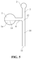
- the skilled person in the art can determine the position where the second channel 5 connects to the first channel 4 depending on his demand. For instance, the second channel 5 connects to the middle portion of the first channel 4 ( FIG. 4 ); alternatively, the second channel 5 and the top opening 12 of the tubular body 10 converge at the end portion of the first channel 4 ( FIG. 5 ).
- FIGS. 6 to 10 are side of embodiments of the present invention showing that the third bulb interconnects with the first bulb based on FIG. 3 in the first embodiment.
- the third bulb 3 interconnects with the second bulb 2 via the third channel 6, and then the second bulb 2 interconnects with the first bulb 1 via the second channel 5.
- the third bulb 3 interconnects with the first bulb 1 via the third channel 6, the second bulb 2 and the second channel 5 sequentially ( FIG. 6 ).
- the third bulb 3 connects with the second channel 5 via the third channel 6, which may act as a branch of the second channel 5, and thus the third bulb 3 interconnects with the first bulb 1 via the third channel 6 and the second channel 5 sequentially ( FIG. 7 ).
- the third bulb 3 directly interconnects with the first bulb 1 via the third channel 5, rather than connecting with the second channel 5 or the second bulb 2 ( FIG. 8 ). Also, it is essential for the third channel 6 to be configured on the position above the upper edge 14 of the anti-backflow compartment 1a. In another specific example, the third bulb 3 interconnects with the first bulb 1 via the third channel 6 and the first channel 4 sequentially, rather than connecting with the second channel 5 or the second bulb 2. Furthermore, the third channel 6 connects to the middle portion of the first channel 4 ( FIG. 9 ); alternatively, the third channel 6 and the top opening 12 of the tubular body 10 converges at the end portion of the first channel 4 ( FIG. 10 ). In addition, the third channel 6 also should be configured on the position above the upper edge 14 of the anti-backflow compartment 1a ( FIGS. 9 and 10 ).
- FIGS. 11 and 12 are side views of embodiments of the present invention showing that the third bulb interconnects with the first bulb based on FIG. 4 in the first embodiment.
- the third bulb 3 interconnects, including but is not limited to, with the first bulb 1 via the third channel 6, the second bulb 2 and the second channel 5 sequentially ( FIG. 11 ), or via the third channel 6 ( FIG. 12 ).
- FIGS. 13 and 14 individually are side views of embodiments of the present invention showing that the third bulb interconnects with the first bulb based on FIG. 5 in the first embodiment.
- the third bulb 3 interconnects with the first bulb 1 via the third channel 6, the second bulb 2 and the second channel 5 sequentially, and the second channel 5 converges with the first channel 4 and the top opening 12 of the tubular body 10 ( FIG. 13 ).
- the third bulb 3 interconnects, including but is not limited to, with the first bulb 1 via the third channel 6 and the first channel 4 sequentially ( FIG. 14 ).
- FIG. 15 is a side view showing that the second bulb interconnects with the first bulb in the second embodiment.
- FIG. 15 is derived and amended based on FIG. 2 .
- the second bulb 2 interconnects with the first bulb 1 via the second channel 5
- the first bulb 1 having the anti-backflow compartment 1a encloses the top opening of the tubular body 10
- the position where the second channel 5 interconnects with the first bulb 1 is higher than that of the upper edge 14 of the anti-backflow compartment 1a.
- FIGS. 16 , 17 and 18 illustrate that the third bulb interconnects with the first bulb based on FIG 15 .
- the third bulb 3 interconnects with the first bulb 1 via the third channel 6, the second bulb 2 and the second channel 5 sequentially in the second embodiment ( FIG. 16 ).
- the third bulb 3 interconnects with the first bulb 1 via the third channel 6 and the second channel 5, and the other terminal of the second channel 5 connects to the second bulb 2 ( FIG. 17 ).
- the third bulb 3 interconnects with the first bulb 1 via the third channel 6, and the position where the third channel 6 interconnects with the first bulb 1 is higher than that of the upper edge 14 of the anti-backflow compartment 1a ( FIG. 18 ).
- the quantitative transfer pipette structure of the present invention by interconnections and combinations of the first to the third bulbs and the second and the third channels, or those of the first to the third bulbs and the first to the third channels.
- the substances in the container may be solid, gel or liquid.
- the capacity of the first bulb should be larger than or equal to that of the tubular body
- the capacity of the second bulb should be smaller than that of the tubular body
- the capacity of the third bulb should be larger than or equal to that of the tubular body.
- the material of the tubular body may be plastic, glass or the combination thereof.
- the materials of all bulbs and channels may be elastic or flexible materials, e.g. plastic, and the tubular body and all of bulbs and channels may be integrated in one piece to be manufactured as an interconnectable and hollow quantitative transfer pipette structure.
- fin can be configured to immobilize all bulbs and the second and the third channels, or immobilize all bulbs and the first to the third channels. It is preferable that all bulbs, the second and the third channels and the fin are situated at the same plane; alternatively, all bulbs, the first to the third channels and the fin are situated at the same plane.
- the straight-lined first, second and third channels shown in the figures are only the exemplary embodiments, and length, shape and three-dimensional configuration can be modified by the skilled person in the art as required.
- the length of the third channel 6 in FIG. 7 may be shortened to approach zero, and thus the third bulb 3 looks like a bulb "budded" from the second channel 5 (not shown).
- the third bulb 3 in FIG. 7 fuses with the second channel 5 to make the third channel 6 disappear, and thus third bulb 3 looks like an expanded portion of the second channel 5.
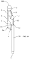
- FIG 19 is a stereo view showing a disposable microtiter transfer pipette according to the first embodiment of the present invention.
- the first bulb 1 interconnects with the top opening 12 of the tubular body 10 via a laterally configured first channel 4
- the second bulb 2 connects to a position higher than that of the upper edge 14 of the first bulb 1 via a bent second channel 5
- the third bulb 3 connects to the bent portion of the second channel 5 via the third channel 6 and then interconnects with the first bulb 1 and the second bulb 2 individually
- the upper edge 14 of the anti-backflow compartment 1a of the first bulb 1 is not higher than the position of the top opening 12 in height.
- a fin 13 strengthens the structural stability among the bulbs 1 to 3 and the channels 4 to 6, so as to facilitate users to hold.
- the first liquid is subjected to the air pressure in the disposable microtiter transfer pipette 100 and aspirated to the tubular body 10 via the opening 11, and the volume of first liquid within the tubular body 10 is a specified value.
- the redundant first liquid flows into the anti-backflow compartment 1a of the first bulb 1 if it exists.
- the tubular body 10 is inserted into the second container (not shown) and the third bulb 3 is pressed, the air pressure within the microtiter transfer pipette 100 drives the first liquid within the tubular body 10 to thoroughly enter into the second container which includes substances (e.g. a second liquid or a solid reagent).
- the first liquid and the second liquid in the second container are sufficiently mixed as a mixture by pressing and releasing the second bulb 2 one or more times. Therefore, the user can transfer the precisely quantified volume of the first liquid into another container to sufficiently mix with the substances in this container as a mixture.
- the mixture can be further processed.
- the user presses the third bulb 3 and inserts the tubular body 10 into the first container.
- the first liquid in the first container is aspirated to the tubular body 10 via the opening 11, and the volume of first liquid within the tubular body 10 still is the specified value as above.
- the redundant first liquid flows into the anti-backflow compartment 1a if it exists.
- the tubular body 10 is inserted into the second container, and the third bulb 3 is pressed to drive the first liquid within the tubular body 10 to thoroughly dispense to the second container.
- the first and the second liquids are sufficiently mixed as the mixture by pressing and releasing the second bulb 2.
- the first bulb 1 may be used to accommodate the redundant first liquid only, and is not pressed and released upon operation.
Landscapes
- Chemical & Material Sciences (AREA)
- Chemical Kinetics & Catalysis (AREA)
- Health & Medical Sciences (AREA)
- Clinical Laboratory Science (AREA)
- Dispersion Chemistry (AREA)
- Physics & Mathematics (AREA)
- Fluid Mechanics (AREA)
- General Physics & Mathematics (AREA)
- Devices For Use In Laboratory Experiments (AREA)
- Sampling And Sample Adjustment (AREA)
- Apparatus Associated With Microorganisms And Enzymes (AREA)
Description
- The present invention relates to a quantitative transfer pipette structure according to
claim 1. - Dropper is a liquid aspiration mechanism containing a tubular body and an expansion part linked thereto, and is configured to transfer the liquid within the tubular body to other place, or mix the liquid and other materials within the tubular body.
- In a conventional dropper, the rubber bulb is put on one end of the tubular body. The user presses the bulb to dispense the air from the tubular body and the bulb, releases the bulb to aspirate liquid into the tubular body through its opening, and presses the bulb again to dispense the aspirated liquid from the tubular body. However, the aspirated or the dispensed volume of the liquid cannot be precisely quantified using such dropper. Furthermore, the excessive liquid may be aspirated into the bulb to cause the bulb blocked and damaged. For example, St. Amand (
U.S. Patent No. 4,779,768 ) disclosed a disposable volumetric dispensing pipette made from a polymer including a hollow tubular body, and three bulbs with two of them including an anti-backflow compartment. However, the said two bulbs including the anti-backflow compartment are disposed in the same height and have the same capacity, and the practical operations of the disposable volumetric dispensing pipette may be limited. - It is therefore the Applicant's attempt to deal with the above situation encountered in the prior art.
- This in mind, the present invention aims at providing a quantitative transfer pipette structure that improves the quantified issues or the liquid mixing issue mentioned above by disposing the anti-backflow compartment of the first bulb. Through the design of the anti-backflow compartment of the first bulb, as well as the sizes and the relative configurations among the first bulb, the second bulb and the third bulb, an operator may manipulate the quantitative transfer pipette structure of the present invention to aspirate a specific volume of liquid into a container, and press and release the bulbs to mix the liquid and the material in the container, so as to achieve the effects of precise quantification and sufficient mixing.
- This achieved by a quantitative transfer pipette structure according to claims. The dependent claims pertain to corresponding further developments and improvements.
- As will be seen more clearly from the detailed description following below, a quantitative transfer pipette structure is provided by the present invention. The quantitative transfer pipette structure includes a hollow tubular body, a first bulb, a second bulb and a third bulb. Among this, the hollow tubular body contains an opening and a top opening. The first bulb contains an anti-backflow compartment having the upper edge being equal to or lower than the position of the top opening in height, wherein the first bulb is situated at the condition (a) or (b) as follows: (a) the first bulb interconnects with the top opening via a first channel, or (b) the first bulb encloses the top opening. The second bulb is configured to interconnect with the first bulb via the condition (c) or (d) as follows: (c) a second channel, or (d) the second channel and the first channel sequentially. The third bulb is configured to interconnect with the first bulb via any one of the conditions (e), (f), (g) and (h) as follows: (e) a third channel, the second bulb and the second channel sequentially; (f) the third channel and the second channel sequentially; (g) the third channel; or (h) the third channel and the first channel sequentially.
-
-
FIG. 1 is a side view showing that the first bulb interconnects with the hollow tubular body via the first channel in the first embodiment not according to the present invention. -
FIG. 2 is a side view showing that the first bulb encloses the hollow tubular body in the second embodiment not according to the present invention. -
FIG. 3 is a side view showing that the second bulb interconnects with the first bulb in the first embodiment not according to the present invention. -
FIG. 4 is a side view showing that the second bulb interconnects with the first bulb in the first embodiment not according to the present invention. -
FIG. 5 is a side view showing that the second bulb interconnects with the first bulb in the first embodiment not according to the present invention. -
FIG. 6 is a side view of an embodiment of the present invention showing that the third bulb interconnects with the first bulb based onFIG. 3 in the first embodiment. -
FIG. 7 is a side view of an embodiment of the present invention showing that the third bulb interconnects with the first bulb based onFIG. 3 in the first embodiment. -
FIG. 8 is a side view of an embodiment of the present invention showing that the third bulb interconnects with the first bulb based onFIG. 3 in the first embodiment. -
FIG. 9 is a side view of an embodiment of the present invention showing that the third bulb interconnects with the first bulb based onFIG. 3 in the first embodiment. -
FIG. 10 is a side view of an embodiment of the present invention showing that the third bulb interconnects with the first bulb based onFIG. 3 in the first embodiment. -
FIG. 11 is a side view of an embodiment of the present invention showing that the third bulb interconnects with the first bulb based onFIG. 4 in the first embodiment. -
FIG. 12 is a side view of an embodiment of the present invention showing that the third bulb interconnects with the first bulb based onFIG. 4 in the first embodiment. -
FIG. 13 is a side view of an embodiment of the present invention showing that the third bulb interconnects with the first bulb based onFIG. 5 in the first embodiment. -
FIG. 14 is a side view of an embodiment of the present invention showing that the third bulb interconnects with the first bulb based onFIG. 5 in the first embodiment. -
FIG. 15 is a side view of an embodiment not covered by the present invention showing that the second bulb interconnects with the first bulb in the second embodiment. -
FIG. 16 is a side view of an embodiment of the present invention showing that the third bulb interconnects with the first bulb in the second embodiment. -
FIG. 17 is a side view of an embodiment of the present invention showing that the third bulb interconnects with the first bulb in the second embodiment. -
FIG. 18 is a side view of an embodiment of the present invention showing that the third bulb interconnects with the first bulb in the second embodiment. -
FIG. 19 is a stereo view showing a disposable microtiter transfer pipette according to an embodiment of the present invention. - The present invention will now be described more specifically with reference to the following embodiments. It is to be noted that the following descriptions of the preferred embodiments of this invention are presented herein for purpose of illustration and description only; they are not intended to be exhaustive or to be limited to the precise form disclosed.
- In the quantitative transfer pipette structure of the present invention, an anti-backflow compartment adjacent to the hollow tubular body is disposed on the top of said tubular body, so that the redundant volume of the first liquid aspirated by the quantitative transfer pipette structure enters into the anti-backflow compartment, and the volume of the first liquid in the tubular body still maintains as a pre-determined value. Upon applying air pressure on or reducing air pressure from the quantitative transfer pipette structure to mix the first liquid and another second liquid, the volume of the mixed liquid existing within the tubular body still maintains as the pre-determined value. The redundant volume of the first liquid in the anti-backflow compartment does not flow back the tubular body to mix with the mixed liquid again and disturb the concentration of the specific substances in the mixed liquid.
- The following embodiments are not according to the invention and are present for illustration purposes only. Please refer to
FIGS. 1 and 2 , which respectively are the side views showing that (1) the first bulb interconnects with the hollow tubular body via the first channel in the first embodiment of the present invention, and (2) the first bulb encloses the hollow tubular body in the second embodiment of the present invention. Thefirst bulb 1 having the anti-backflow compartment 1a interconnects with the top opening 12 of thetubular body 10 via the first channel 4 (FIG. 1 ), or thefirst bulb 1 having the anti-backflow compartment 1a encloses the top opening 12 of the tubular body 10 (FIG. 2 ), and theupper edge 14 of the anti-backflow compartment 1a (as shown in the dash line inFIGS. 1 and 2 ) is equal to or lower than the position of the top opening 12 in height. Therefore, the liquid (not shown) enters into the hollowtubular body 10 from theopening 11, and then the redundant volume of the liquid flows into the anti-backflow compartment 1a via thefirst channel 4, or directly flows into the anti-backflow compartment 1a in the absence of thefirst channel 4. The redundant volume of the liquid stays at the anti-backflow compartment 1a, and does not flow back thetubular body 10 even though other bulbs are operated. In addition, inFIG. 1 , thefirst channel 4 preferably interconnects with thetubular body 10 and thefirst bulb 1 by the lateral or horizontal configuration. - The following embodiments are not according to the invention and are present for illustration purposes only. Please refer to
FIGS. 3, 4 and5 , which are side views showing that the second bulb interconnects with the first bulb in the first embodiment. Thesecond bulb 2 interconnects with thefirst bulb 1 via thesecond channel 5 in various ways in the first embodiment. In one specific example, thesecond bulb 2 is configured above the top edge of thefirst bulb 1, and interconnects with thefirst bulb 1 via the second channel 5 (FIG. 3 ). In another specific example, thesecond bulb 2 connects with thefirst channel 4 via thesecond channel 5, so that thesecond bulb 2 interconnects with thefirst bulb 1 via thesecond channel 5 and thefirst channel 4 sequentially. The skilled person in the art can determine the position where thesecond channel 5 connects to thefirst channel 4 depending on his demand. For instance, thesecond channel 5 connects to the middle portion of the first channel 4 (FIG. 4 ); alternatively, thesecond channel 5 and the top opening 12 of thetubular body 10 converge at the end portion of the first channel 4 (FIG. 5 ). - Please refer to
FIGS. 6 to 10 , which are side of embodiments of the present invention showing that the third bulb interconnects with the first bulb based onFIG. 3 in the first embodiment. In one specific example, thethird bulb 3 interconnects with thesecond bulb 2 via thethird channel 6, and then thesecond bulb 2 interconnects with thefirst bulb 1 via thesecond channel 5. Thus, thethird bulb 3 interconnects with thefirst bulb 1 via thethird channel 6, thesecond bulb 2 and thesecond channel 5 sequentially (FIG. 6 ). In one specific example, thethird bulb 3 connects with thesecond channel 5 via thethird channel 6, which may act as a branch of thesecond channel 5, and thus thethird bulb 3 interconnects with thefirst bulb 1 via thethird channel 6 and thesecond channel 5 sequentially (FIG. 7 ). In another specific example, thethird bulb 3 directly interconnects with thefirst bulb 1 via thethird channel 5, rather than connecting with thesecond channel 5 or the second bulb 2 (FIG. 8 ). Also, it is essential for thethird channel 6 to be configured on the position above theupper edge 14 of the anti-backflow compartment 1a. In another specific example, thethird bulb 3 interconnects with thefirst bulb 1 via thethird channel 6 and thefirst channel 4 sequentially, rather than connecting with thesecond channel 5 or thesecond bulb 2. Furthermore, thethird channel 6 connects to the middle portion of the first channel 4 (FIG. 9 ); alternatively, thethird channel 6 and thetop opening 12 of thetubular body 10 converges at the end portion of the first channel 4 (FIG. 10 ). In addition, thethird channel 6 also should be configured on the position above theupper edge 14 of the anti-backflow compartment 1a (FIGS. 9 and10 ). - Please refer to
FIGS. 11 and 12 , which individually are side views of embodiments of the present invention showing that the third bulb interconnects with the first bulb based onFIG. 4 in the first embodiment. - As described in the illustrations of
FIGS. 6 to 10 , thethird bulb 3 interconnects, including but is not limited to, with thefirst bulb 1 via thethird channel 6, thesecond bulb 2 and thesecond channel 5 sequentially (FIG. 11 ), or via the third channel 6 (FIG. 12 ). Please refer toFIGS. 13 and 14 , which individually are side views of embodiments of the present invention showing that the third bulb interconnects with the first bulb based onFIG. 5 in the first embodiment. - As described in the illustrations of
FIGS. 6 to 10 , thethird bulb 3 interconnects with thefirst bulb 1 via thethird channel 6, thesecond bulb 2 and thesecond channel 5 sequentially, and thesecond channel 5 converges with thefirst channel 4 and thetop opening 12 of the tubular body 10 (FIG. 13 ). Alternatively, thethird bulb 3 interconnects, including but is not limited to, with thefirst bulb 1 via thethird channel 6 and thefirst channel 4 sequentially (FIG. 14 ). - The following embodiment is not according to the invention and is present for illustration purposes only. Please refer to
FIG. 15 , which is a side view showing that the second bulb interconnects with the first bulb in the second embodiment.FIG. 15 is derived and amended based onFIG. 2 . InFIG. 15 , thesecond bulb 2 interconnects with thefirst bulb 1 via thesecond channel 5, thefirst bulb 1 having the anti-backflow compartment 1a encloses the top opening of thetubular body 10, and the position where thesecond channel 5 interconnects with thefirst bulb 1 is higher than that of theupper edge 14 of the anti-backflow compartment 1a. - Please refer to
FIGS. 16 ,17 and 18 , which illustrate that the third bulb interconnects with the first bulb based onFIG 15 . As described in the illustrations ofFIGS. 6 to 10 , thethird bulb 3 interconnects with thefirst bulb 1 via thethird channel 6, thesecond bulb 2 and thesecond channel 5 sequentially in the second embodiment (FIG. 16 ). Alternatively, thethird bulb 3 interconnects with thefirst bulb 1 via thethird channel 6 and thesecond channel 5, and the other terminal of thesecond channel 5 connects to the second bulb 2 (FIG. 17 ). Alternatively, thethird bulb 3 interconnects with thefirst bulb 1 via thethird channel 6, and the position where thethird channel 6 interconnects with thefirst bulb 1 is higher than that of theupper edge 14 of the anti-backflow compartment 1a (FIG. 18 ). - From embodiments above, it is known that the precise volumetric quantitation for liquid and the sufficient mixing of the quantified liquid volume with the substance in the container are achieved by the quantitative transfer pipette structure of the present invention by interconnections and combinations of the first to the third bulbs and the second and the third channels, or those of the first to the third bulbs and the first to the third channels. Furthermore, the substances in the container may be solid, gel or liquid. In the quantitative transfer pipette structure of the present invention, the capacity of the first bulb should be larger than or equal to that of the tubular body, the capacity of the second bulb should be smaller than that of the tubular body, and the capacity of the third bulb should be larger than or equal to that of the tubular body. The material of the tubular body may be plastic, glass or the combination thereof. The materials of all bulbs and channels may be elastic or flexible materials, e.g. plastic, and the tubular body and all of bulbs and channels may be integrated in one piece to be manufactured as an interconnectable and hollow quantitative transfer pipette structure.
- To strength the structural stability of the quantitative transfer pipette structure and facilitate users' holding, fin can be configured to immobilize all bulbs and the second and the third channels, or immobilize all bulbs and the first to the third channels. It is preferable that all bulbs, the second and the third channels and the fin are situated at the same plane; alternatively, all bulbs, the first to the third channels and the fin are situated at the same plane.
- The straight-lined first, second and third channels shown in the figures are only the exemplary embodiments, and length, shape and three-dimensional configuration can be modified by the skilled person in the art as required. For instance, the length of the
third channel 6 inFIG. 7 may be shortened to approach zero, and thus thethird bulb 3 looks like a bulb "budded" from the second channel 5 (not shown). For instance, thethird bulb 3 inFIG. 7 fuses with thesecond channel 5 to make thethird channel 6 disappear, and thusthird bulb 3 looks like an expanded portion of thesecond channel 5. - Please refer to
FIG 19 , which is a stereo view showing a disposable microtiter transfer pipette according to the first embodiment of the present invention. In the disposable microtiter transfer pipette ofFIG. 19 , thefirst bulb 1 interconnects with thetop opening 12 of thetubular body 10 via a laterally configuredfirst channel 4, thesecond bulb 2 connects to a position higher than that of theupper edge 14 of thefirst bulb 1 via a bentsecond channel 5, thethird bulb 3 connects to the bent portion of thesecond channel 5 via thethird channel 6 and then interconnects with thefirst bulb 1 and thesecond bulb 2 individually, and theupper edge 14 of the anti-backflow compartment 1a of thefirst bulb 1 is not higher than the position of thetop opening 12 in height. InFIG. 19 , afin 13 strengthens the structural stability among thebulbs 1 to 3 and thechannels 4 to 6, so as to facilitate users to hold. - The user presses the
first bulb 1 of the disposablemicrotiter transfer pipette 100 and inserts thetubular body 10 into the first liquid of the first container (not shown). Upon releasing thefirst bulb 1, the first liquid is subjected to the air pressure in the disposablemicrotiter transfer pipette 100 and aspirated to thetubular body 10 via theopening 11, and the volume of first liquid within thetubular body 10 is a specified value. The redundant first liquid flows into the anti-backflow compartment 1a of thefirst bulb 1 if it exists. Subsequently, thetubular body 10 is inserted into the second container (not shown) and thethird bulb 3 is pressed, the air pressure within themicrotiter transfer pipette 100 drives the first liquid within thetubular body 10 to thoroughly enter into the second container which includes substances (e.g. a second liquid or a solid reagent). The first liquid and the second liquid in the second container are sufficiently mixed as a mixture by pressing and releasing thesecond bulb 2 one or more times. Therefore, the user can transfer the precisely quantified volume of the first liquid into another container to sufficiently mix with the substances in this container as a mixture. The mixture can be further processed. - In another operational method, the user presses the
third bulb 3 and inserts thetubular body 10 into the first container. Similarly, upon releasing thethird bulb 3, the first liquid in the first container is aspirated to thetubular body 10 via theopening 11, and the volume of first liquid within thetubular body 10 still is the specified value as above. The redundant first liquid flows into the anti-backflow compartment 1a if it exists. Subsequently, thetubular body 10 is inserted into the second container, and thethird bulb 3 is pressed to drive the first liquid within thetubular body 10 to thoroughly dispense to the second container. The first and the second liquids are sufficiently mixed as the mixture by pressing and releasing thesecond bulb 2. In this method, thefirst bulb 1 may be used to accommodate the redundant first liquid only, and is not pressed and released upon operation. - While the invention has been described in terms of what is presently considered to be the most practical and preferred embodiments, it is to be understood that the invention need not be limited to the disclosed embodiments. On the contrary, it is intended to cover various modifications and similar arrangements included within the scope of the appended claims, which are to be accorded with the broadest interpretation so as to encompass all such modifications and similar structures.
Claims (9)
- A quantitative transfer pipette structure (100), comprising:a hollow tubular body (10) containing an opening (11) and a top opening (12);a first bulb (1) containing an anti-backflow compartment (1a) having an upper edge (14) being equal to or lower than the position of the top opening (12) in height, wherein the first bulb (1) is situated at one of the conditions (a) and (b) as follows:(a) the first bulb (1) interconnects with the top opening (12) via a first channel (4), and(b) the first bulb (1) encloses the top opening (12);a second bulb (2) configured to interconnect with the first bulb (1) via one of the conditions (c) and (d) as follows:(c) a second channel (5), and(d) the second channel (5) and the first channel (4) sequentially; anda third bulb (3) configured to interconnect with the first bulb (1) via one of the conditions (e), (f), (g) and (h) as follows:(e) a third channel (6), the second bulb (2) and the second channel (5) sequentially;(f) the third channel (6) and the second channel (5) sequentially;(g) the third channel (6); and(h) the third channel (6) and the first channel (4) sequentially;the quantitative transfer pipette structure (100) being characterized in that a capacity of the first bulb (1) is equal to or larger than that of the hollow tubular body (10), a capacity of the second bulb (2) is smaller than that of the hollow tubular body (10), and a capacity of the third bulb (3) is equal to or larger than that of the hollow tubular body (10).
- The quantitative transfer pipette structure (100) according to Claim 1, characterized in that the position where the second channel (5) connects with the first bulb (1) is higher than that of the upper edge (14) when the second bulb (2) interconnects with the first bulb (1) via the second channel (5).
- The quantitative transfer pipette structure (100) according to Claim 1, characterized in that the position where the second channel (5) connects with the first channel (4) is higher than that of the upper edge (14) when the second bulb (2) interconnects with the first bulb (1) via the second channel (5) and the first channel (4) sequentially.
- The quantitative transfer pipette structure (100) according to Claim 1, characterized in that the third bulb (3) interconnects with the first bulb (1) via the third channel (6) and the second channel (5) sequentially, and the third bulb (3) interconnects with the second bulb (2) via the third channel (6) and the second channel (5) sequentially.
- The quantitative transfer pipette structure (100) according to Claim 1, characterized in that the position where the third channel (6) connects with one of the first bulb (1) and the first channel (4) is higher than that of the upper edge (14).
- The quantitative transfer pipette structure (100) according to any one of Claims 1 to 5, characterized in that the material of the hollow tubular body (10) is plastic, glass or a composite thereof.
- The quantitative transfer pipette structure (100) according to Claim 1, characterized in that the quantitative transfer pipette structure (100) further comprises a fin (13) configured to connect with and fix the first bulb (1), the second bulb (2), the third bulb (3), the second channel (5) and the third channel (6).
- The quantitative transfer pipette structure (100) according to Claim 7, characterized in that the first bulb (1), the second bulb (2), the third bulb (3), the second channel (5), the third channel (6) and the fin (13) is situated at the same plane.
- The quantitative transfer pipette structure (100) according to Claim 1, characterized in that the first bulb (1) interconnects with the top opening (12) via the laterally configured first channel (4), the second channel (5) is bent-shaped, the second bulb (2) connects with the upper edge of the first bulb (1) via the second channel (5), the third bulb (3) connects with the bent portion of the second channel (5) via the third channel (6) and then interconnects with first bulb (1) and the second bulb (2) individually, and the upper edge (14) of the anti-backflow compartment (1a) is equal to or lower than the position of the top opening (12) in height.
Applications Claiming Priority (1)
| Application Number | Priority Date | Filing Date | Title |
|---|---|---|---|
| TW109208405U TWM606339U (en) | 2020-07-02 | 2020-07-02 | Quantitative transfer pipette structure |
Publications (2)
| Publication Number | Publication Date |
|---|---|
| EP3932558A1 EP3932558A1 (en) | 2022-01-05 |
| EP3932558B1 true EP3932558B1 (en) | 2024-03-20 |
Family
ID=72087948
Family Applications (1)
| Application Number | Title | Priority Date | Filing Date |
|---|---|---|---|
| EP20191106.2A Active EP3932558B1 (en) | 2020-07-02 | 2020-08-14 | Quantitative transfer pipette structure |
Country Status (4)
| Country | Link |
|---|---|
| US (1) | US11624641B2 (en) |
| EP (1) | EP3932558B1 (en) |
| JP (1) | JP3229722U (en) |
| TW (1) | TWM606339U (en) |
Families Citing this family (1)
| Publication number | Priority date | Publication date | Assignee | Title |
|---|---|---|---|---|
| TWM606339U (en) * | 2020-07-02 | 2021-01-11 | 新加坡商克雷多診斷生物醫學私人有限公司 | Quantitative transfer pipette structure |
Family Cites Families (8)
| Publication number | Priority date | Publication date | Assignee | Title |
|---|---|---|---|---|
| US2237213A (en) * | 1939-05-31 | 1941-04-01 | Ralph F Brown | Pipette |
| US4779768A (en) * | 1987-07-24 | 1988-10-25 | St. Amand Manufacturing Co., Inc. | Volumetric dispensing pipette |
| US5125278A (en) * | 1990-10-18 | 1992-06-30 | V-Tech, Inc. | Volumetric pipette |
| US20020102184A1 (en) * | 2001-01-29 | 2002-08-01 | Co Rochester Tiao-Te | Liquid dispenser |
| US20170036203A1 (en) * | 2015-08-07 | 2017-02-09 | Nalge Nunc International Corporation | Slow draw transfer pipettes and related methods |
| US10814320B2 (en) * | 2016-08-08 | 2020-10-27 | Nalge Nunc International Corporation | Capillary transfer pipettes and related methods |
| CN106475164B (en) | 2016-10-24 | 2019-01-11 | 深圳市孔雀生物科技有限公司 | A kind of combined centrifugal device |
| TWM606339U (en) * | 2020-07-02 | 2021-01-11 | 新加坡商克雷多診斷生物醫學私人有限公司 | Quantitative transfer pipette structure |
-
2020
- 2020-07-02 TW TW109208405U patent/TWM606339U/en unknown
- 2020-08-03 US US16/984,111 patent/US11624641B2/en active Active
- 2020-08-14 EP EP20191106.2A patent/EP3932558B1/en active Active
- 2020-09-28 JP JP2020004176U patent/JP3229722U/en active Active
Also Published As
| Publication number | Publication date |
|---|---|
| US20220003586A1 (en) | 2022-01-06 |
| JP3229722U (en) | 2020-12-17 |
| US11624641B2 (en) | 2023-04-11 |
| EP3932558A1 (en) | 2022-01-05 |
| TWM606339U (en) | 2021-01-11 |
Similar Documents
| Publication | Publication Date | Title |
|---|---|---|
| EP1488221B1 (en) | Fluid-transfer collection assembly and method of using the same | |
| US5266266A (en) | Specimen test unit | |
| EP3645998B1 (en) | Sample filtration device and method | |
| CA1302370C (en) | Method and apparatus for dispensing liquids | |
| EP3381559B1 (en) | Biological fluid micro-sample management device | |
| US9089841B2 (en) | Method of sampling specimen, test method and dropping pipette and specimen sampler to be used therein | |
| USRE37734E1 (en) | Dispensing bulb | |
| US20200370037A1 (en) | Sample extraction and preparation device | |
| EP3758607B1 (en) | Biological fluid collection device and collection module | |
| US9116089B2 (en) | Device for filtering blood | |
| JP2015527582A (en) | Multi-part component device for extracting plasma from blood | |
| EP3932558A1 (en) | Quantitative transfer pipette structure | |
| US4326959A (en) | Blood separator and dispenser | |
| US20160175842A1 (en) | Device for Introducing a Liquid Sample into a Microfluidic System | |
| JP2003159237A (en) | Transfer device | |
| US4487696A (en) | Blood separator and dispenser | |
| US5125278A (en) | Volumetric pipette | |
| EP0572637B1 (en) | Specimen test unit | |
| JP7561625B2 (en) | Biological Fluid Collection System | |
| KR20020090923A (en) | Device for processing samples, use of the device, and method for producing the device | |
| US9861978B2 (en) | Mechanically actuated vacuum controlled fluid collection | |
| CN113167785A (en) | Microfluidic device | |
| JP2001145830A (en) | Constant volume liquid transfer device and method for transferring liquid | |
| EP0405026A1 (en) | Unitary centrifuge tube and separable dispensing receptacle | |
| JP2007152228A (en) | Micro chemical chip |
Legal Events
| Date | Code | Title | Description |
|---|---|---|---|
| PUAI | Public reference made under article 153(3) epc to a published international application that has entered the european phase |
Free format text: ORIGINAL CODE: 0009012 |
|
| STAA | Information on the status of an ep patent application or granted ep patent |
Free format text: STATUS: REQUEST FOR EXAMINATION WAS MADE |
|
| 17P | Request for examination filed |
Effective date: 20210607 |
|
| AK | Designated contracting states |
Kind code of ref document: A1 Designated state(s): AL AT BE BG CH CY CZ DE DK EE ES FI FR GB GR HR HU IE IS IT LI LT LU LV MC MK MT NL NO PL PT RO RS SE SI SK SM TR |
|
| B565 | Issuance of search results under rule 164(2) epc |
Effective date: 20210125 |
|
| STAA | Information on the status of an ep patent application or granted ep patent |
Free format text: STATUS: EXAMINATION IS IN PROGRESS |
|
| 17Q | First examination report despatched |
Effective date: 20230719 |
|
| GRAP | Despatch of communication of intention to grant a patent |
Free format text: ORIGINAL CODE: EPIDOSNIGR1 |
|
| STAA | Information on the status of an ep patent application or granted ep patent |
Free format text: STATUS: GRANT OF PATENT IS INTENDED |
|
| INTG | Intention to grant announced |
Effective date: 20231031 |
|
| RAP3 | Party data changed (applicant data changed or rights of an application transferred) |
Owner name: CREDO DIAGNOSTICS BIOMEDICAL PTE. LTD. |
|
| GRAS | Grant fee paid |
Free format text: ORIGINAL CODE: EPIDOSNIGR3 |
|
| GRAA | (expected) grant |
Free format text: ORIGINAL CODE: 0009210 |
|
| STAA | Information on the status of an ep patent application or granted ep patent |
Free format text: STATUS: THE PATENT HAS BEEN GRANTED |
|
| AK | Designated contracting states |
Kind code of ref document: B1 Designated state(s): AL AT BE BG CH CY CZ DE DK EE ES FI FR GB GR HR HU IE IS IT LI LT LU LV MC MK MT NL NO PL PT RO RS SE SI SK SM TR |
|
| REG | Reference to a national code |
Ref country code: GB Ref legal event code: FG4D |
|
| REG | Reference to a national code |
Ref country code: CH Ref legal event code: EP |
|
| REG | Reference to a national code |
Ref country code: DE Ref legal event code: R096 Ref document number: 602020027422 Country of ref document: DE |
|
| REG | Reference to a national code |
Ref country code: IE Ref legal event code: FG4D |
|
| PG25 | Lapsed in a contracting state [announced via postgrant information from national office to epo] |
Ref country code: LT Free format text: LAPSE BECAUSE OF FAILURE TO SUBMIT A TRANSLATION OF THE DESCRIPTION OR TO PAY THE FEE WITHIN THE PRESCRIBED TIME-LIMIT Effective date: 20240320 |
|
| REG | Reference to a national code |
Ref country code: LT Ref legal event code: MG9D |
|
| PG25 | Lapsed in a contracting state [announced via postgrant information from national office to epo] |
Ref country code: GR Free format text: LAPSE BECAUSE OF FAILURE TO SUBMIT A TRANSLATION OF THE DESCRIPTION OR TO PAY THE FEE WITHIN THE PRESCRIBED TIME-LIMIT Effective date: 20240621 |
|
| PG25 | Lapsed in a contracting state [announced via postgrant information from national office to epo] |
Ref country code: RS Free format text: LAPSE BECAUSE OF FAILURE TO SUBMIT A TRANSLATION OF THE DESCRIPTION OR TO PAY THE FEE WITHIN THE PRESCRIBED TIME-LIMIT Effective date: 20240620 Ref country code: HR Free format text: LAPSE BECAUSE OF FAILURE TO SUBMIT A TRANSLATION OF THE DESCRIPTION OR TO PAY THE FEE WITHIN THE PRESCRIBED TIME-LIMIT Effective date: 20240320 |
|
| REG | Reference to a national code |
Ref country code: NL Ref legal event code: MP Effective date: 20240320 |
|
| PG25 | Lapsed in a contracting state [announced via postgrant information from national office to epo] |
Ref country code: RS Free format text: LAPSE BECAUSE OF FAILURE TO SUBMIT A TRANSLATION OF THE DESCRIPTION OR TO PAY THE FEE WITHIN THE PRESCRIBED TIME-LIMIT Effective date: 20240620 Ref country code: NO Free format text: LAPSE BECAUSE OF FAILURE TO SUBMIT A TRANSLATION OF THE DESCRIPTION OR TO PAY THE FEE WITHIN THE PRESCRIBED TIME-LIMIT Effective date: 20240620 Ref country code: LT Free format text: LAPSE BECAUSE OF FAILURE TO SUBMIT A TRANSLATION OF THE DESCRIPTION OR TO PAY THE FEE WITHIN THE PRESCRIBED TIME-LIMIT Effective date: 20240320 Ref country code: HR Free format text: LAPSE BECAUSE OF FAILURE TO SUBMIT A TRANSLATION OF THE DESCRIPTION OR TO PAY THE FEE WITHIN THE PRESCRIBED TIME-LIMIT Effective date: 20240320 Ref country code: GR Free format text: LAPSE BECAUSE OF FAILURE TO SUBMIT A TRANSLATION OF THE DESCRIPTION OR TO PAY THE FEE WITHIN THE PRESCRIBED TIME-LIMIT Effective date: 20240621 Ref country code: FI Free format text: LAPSE BECAUSE OF FAILURE TO SUBMIT A TRANSLATION OF THE DESCRIPTION OR TO PAY THE FEE WITHIN THE PRESCRIBED TIME-LIMIT Effective date: 20240320 Ref country code: BG Free format text: LAPSE BECAUSE OF FAILURE TO SUBMIT A TRANSLATION OF THE DESCRIPTION OR TO PAY THE FEE WITHIN THE PRESCRIBED TIME-LIMIT Effective date: 20240320 |
|
| REG | Reference to a national code |
Ref country code: AT Ref legal event code: MK05 Ref document number: 1667368 Country of ref document: AT Kind code of ref document: T Effective date: 20240320 |
|
| PG25 | Lapsed in a contracting state [announced via postgrant information from national office to epo] |
Ref country code: SE Free format text: LAPSE BECAUSE OF FAILURE TO SUBMIT A TRANSLATION OF THE DESCRIPTION OR TO PAY THE FEE WITHIN THE PRESCRIBED TIME-LIMIT Effective date: 20240320 Ref country code: LV Free format text: LAPSE BECAUSE OF FAILURE TO SUBMIT A TRANSLATION OF THE DESCRIPTION OR TO PAY THE FEE WITHIN THE PRESCRIBED TIME-LIMIT Effective date: 20240320 |
|
| PG25 | Lapsed in a contracting state [announced via postgrant information from national office to epo] |
Ref country code: NL Free format text: LAPSE BECAUSE OF FAILURE TO SUBMIT A TRANSLATION OF THE DESCRIPTION OR TO PAY THE FEE WITHIN THE PRESCRIBED TIME-LIMIT Effective date: 20240320 |
|
| REG | Reference to a national code |
Ref country code: DE Ref legal event code: R082 Ref document number: 602020027422 Country of ref document: DE Representative=s name: STRAUS, ALEXANDER, DIPL.-CHEM.UNIV. DR.PHIL., DE |
|
| PG25 | Lapsed in a contracting state [announced via postgrant information from national office to epo] |
Ref country code: NL Free format text: LAPSE BECAUSE OF FAILURE TO SUBMIT A TRANSLATION OF THE DESCRIPTION OR TO PAY THE FEE WITHIN THE PRESCRIBED TIME-LIMIT Effective date: 20240320 |
|
| PG25 | Lapsed in a contracting state [announced via postgrant information from national office to epo] |
Ref country code: IS Free format text: LAPSE BECAUSE OF FAILURE TO SUBMIT A TRANSLATION OF THE DESCRIPTION OR TO PAY THE FEE WITHIN THE PRESCRIBED TIME-LIMIT Effective date: 20240720 |
|
| PG25 | Lapsed in a contracting state [announced via postgrant information from national office to epo] |
Ref country code: SM Free format text: LAPSE BECAUSE OF FAILURE TO SUBMIT A TRANSLATION OF THE DESCRIPTION OR TO PAY THE FEE WITHIN THE PRESCRIBED TIME-LIMIT Effective date: 20240320 Ref country code: PT Free format text: LAPSE BECAUSE OF FAILURE TO SUBMIT A TRANSLATION OF THE DESCRIPTION OR TO PAY THE FEE WITHIN THE PRESCRIBED TIME-LIMIT Effective date: 20240722 |
|
| PG25 | Lapsed in a contracting state [announced via postgrant information from national office to epo] |
Ref country code: ES Free format text: LAPSE BECAUSE OF FAILURE TO SUBMIT A TRANSLATION OF THE DESCRIPTION OR TO PAY THE FEE WITHIN THE PRESCRIBED TIME-LIMIT Effective date: 20240320 |
|
| PG25 | Lapsed in a contracting state [announced via postgrant information from national office to epo] |
Ref country code: EE Free format text: LAPSE BECAUSE OF FAILURE TO SUBMIT A TRANSLATION OF THE DESCRIPTION OR TO PAY THE FEE WITHIN THE PRESCRIBED TIME-LIMIT Effective date: 20240320 Ref country code: CZ Free format text: LAPSE BECAUSE OF FAILURE TO SUBMIT A TRANSLATION OF THE DESCRIPTION OR TO PAY THE FEE WITHIN THE PRESCRIBED TIME-LIMIT Effective date: 20240320 |
|
| PG25 | Lapsed in a contracting state [announced via postgrant information from national office to epo] |
Ref country code: AT Free format text: LAPSE BECAUSE OF FAILURE TO SUBMIT A TRANSLATION OF THE DESCRIPTION OR TO PAY THE FEE WITHIN THE PRESCRIBED TIME-LIMIT Effective date: 20240320 |
|
| PG25 | Lapsed in a contracting state [announced via postgrant information from national office to epo] |
Ref country code: PL Free format text: LAPSE BECAUSE OF FAILURE TO SUBMIT A TRANSLATION OF THE DESCRIPTION OR TO PAY THE FEE WITHIN THE PRESCRIBED TIME-LIMIT Effective date: 20240320 |
|
| PG25 | Lapsed in a contracting state [announced via postgrant information from national office to epo] |
Ref country code: SK Free format text: LAPSE BECAUSE OF FAILURE TO SUBMIT A TRANSLATION OF THE DESCRIPTION OR TO PAY THE FEE WITHIN THE PRESCRIBED TIME-LIMIT Effective date: 20240320 |
|
| PG25 | Lapsed in a contracting state [announced via postgrant information from national office to epo] |
Ref country code: SM Free format text: LAPSE BECAUSE OF FAILURE TO SUBMIT A TRANSLATION OF THE DESCRIPTION OR TO PAY THE FEE WITHIN THE PRESCRIBED TIME-LIMIT Effective date: 20240320 Ref country code: SK Free format text: LAPSE BECAUSE OF FAILURE TO SUBMIT A TRANSLATION OF THE DESCRIPTION OR TO PAY THE FEE WITHIN THE PRESCRIBED TIME-LIMIT Effective date: 20240320 Ref country code: RO Free format text: LAPSE BECAUSE OF FAILURE TO SUBMIT A TRANSLATION OF THE DESCRIPTION OR TO PAY THE FEE WITHIN THE PRESCRIBED TIME-LIMIT Effective date: 20240320 Ref country code: PT Free format text: LAPSE BECAUSE OF FAILURE TO SUBMIT A TRANSLATION OF THE DESCRIPTION OR TO PAY THE FEE WITHIN THE PRESCRIBED TIME-LIMIT Effective date: 20240722 Ref country code: PL Free format text: LAPSE BECAUSE OF FAILURE TO SUBMIT A TRANSLATION OF THE DESCRIPTION OR TO PAY THE FEE WITHIN THE PRESCRIBED TIME-LIMIT Effective date: 20240320 Ref country code: IS Free format text: LAPSE BECAUSE OF FAILURE TO SUBMIT A TRANSLATION OF THE DESCRIPTION OR TO PAY THE FEE WITHIN THE PRESCRIBED TIME-LIMIT Effective date: 20240720 Ref country code: ES Free format text: LAPSE BECAUSE OF FAILURE TO SUBMIT A TRANSLATION OF THE DESCRIPTION OR TO PAY THE FEE WITHIN THE PRESCRIBED TIME-LIMIT Effective date: 20240320 Ref country code: EE Free format text: LAPSE BECAUSE OF FAILURE TO SUBMIT A TRANSLATION OF THE DESCRIPTION OR TO PAY THE FEE WITHIN THE PRESCRIBED TIME-LIMIT Effective date: 20240320 Ref country code: CZ Free format text: LAPSE BECAUSE OF FAILURE TO SUBMIT A TRANSLATION OF THE DESCRIPTION OR TO PAY THE FEE WITHIN THE PRESCRIBED TIME-LIMIT Effective date: 20240320 Ref country code: AT Free format text: LAPSE BECAUSE OF FAILURE TO SUBMIT A TRANSLATION OF THE DESCRIPTION OR TO PAY THE FEE WITHIN THE PRESCRIBED TIME-LIMIT Effective date: 20240320 |
|
| PG25 | Lapsed in a contracting state [announced via postgrant information from national office to epo] |
Ref country code: IT Free format text: LAPSE BECAUSE OF FAILURE TO SUBMIT A TRANSLATION OF THE DESCRIPTION OR TO PAY THE FEE WITHIN THE PRESCRIBED TIME-LIMIT Effective date: 20240320 |
|
| REG | Reference to a national code |
Ref country code: DE Ref legal event code: R097 Ref document number: 602020027422 Country of ref document: DE |
|
| PG25 | Lapsed in a contracting state [announced via postgrant information from national office to epo] |
Ref country code: IT Free format text: LAPSE BECAUSE OF FAILURE TO SUBMIT A TRANSLATION OF THE DESCRIPTION OR TO PAY THE FEE WITHIN THE PRESCRIBED TIME-LIMIT Effective date: 20240320 |
|
| PG25 | Lapsed in a contracting state [announced via postgrant information from national office to epo] |
Ref country code: DK Free format text: LAPSE BECAUSE OF FAILURE TO SUBMIT A TRANSLATION OF THE DESCRIPTION OR TO PAY THE FEE WITHIN THE PRESCRIBED TIME-LIMIT Effective date: 20240320 |
|
| PLBE | No opposition filed within time limit |
Free format text: ORIGINAL CODE: 0009261 |
|
| STAA | Information on the status of an ep patent application or granted ep patent |
Free format text: STATUS: NO OPPOSITION FILED WITHIN TIME LIMIT |
|
| PG25 | Lapsed in a contracting state [announced via postgrant information from national office to epo] |
Ref country code: DK Free format text: LAPSE BECAUSE OF FAILURE TO SUBMIT A TRANSLATION OF THE DESCRIPTION OR TO PAY THE FEE WITHIN THE PRESCRIBED TIME-LIMIT Effective date: 20240320 |
|
| 26N | No opposition filed |
Effective date: 20241223 |
|
| REG | Reference to a national code |
Ref country code: CH Ref legal event code: PL |
|
| PG25 | Lapsed in a contracting state [announced via postgrant information from national office to epo] |
Ref country code: LU Free format text: LAPSE BECAUSE OF NON-PAYMENT OF DUE FEES Effective date: 20240814 |
|
| PG25 | Lapsed in a contracting state [announced via postgrant information from national office to epo] |
Ref country code: MC Free format text: LAPSE BECAUSE OF FAILURE TO SUBMIT A TRANSLATION OF THE DESCRIPTION OR TO PAY THE FEE WITHIN THE PRESCRIBED TIME-LIMIT Effective date: 20240320 Ref country code: SI Free format text: LAPSE BECAUSE OF FAILURE TO SUBMIT A TRANSLATION OF THE DESCRIPTION OR TO PAY THE FEE WITHIN THE PRESCRIBED TIME-LIMIT Effective date: 20240320 Ref country code: CH Free format text: LAPSE BECAUSE OF NON-PAYMENT OF DUE FEES Effective date: 20240831 |
|
| REG | Reference to a national code |
Ref country code: BE Ref legal event code: MM Effective date: 20240831 |
|
| PGFP | Annual fee paid to national office [announced via postgrant information from national office to epo] |
Ref country code: GB Payment date: 20250602 Year of fee payment: 6 |
|
| PG25 | Lapsed in a contracting state [announced via postgrant information from national office to epo] |
Ref country code: BE Free format text: LAPSE BECAUSE OF NON-PAYMENT OF DUE FEES Effective date: 20240831 |
|
| PGFP | Annual fee paid to national office [announced via postgrant information from national office to epo] |
Ref country code: FR Payment date: 20250502 Year of fee payment: 6 |
|
| PG25 | Lapsed in a contracting state [announced via postgrant information from national office to epo] |
Ref country code: IE Free format text: LAPSE BECAUSE OF NON-PAYMENT OF DUE FEES Effective date: 20240814 |
|
| PGFP | Annual fee paid to national office [announced via postgrant information from national office to epo] |
Ref country code: DE Payment date: 20250831 Year of fee payment: 6 |
|
| PG25 | Lapsed in a contracting state [announced via postgrant information from national office to epo] |
Ref country code: CY Free format text: LAPSE BECAUSE OF FAILURE TO SUBMIT A TRANSLATION OF THE DESCRIPTION OR TO PAY THE FEE WITHIN THE PRESCRIBED TIME-LIMIT; INVALID AB INITIO Effective date: 20200814 |
|
| PG25 | Lapsed in a contracting state [announced via postgrant information from national office to epo] |
Ref country code: HU Free format text: LAPSE BECAUSE OF FAILURE TO SUBMIT A TRANSLATION OF THE DESCRIPTION OR TO PAY THE FEE WITHIN THE PRESCRIBED TIME-LIMIT; INVALID AB INITIO Effective date: 20200814 |