EP3932461A1 - Torque device - Google Patents
Torque device Download PDFInfo
- Publication number
- EP3932461A1 EP3932461A1 EP20770294.5A EP20770294A EP3932461A1 EP 3932461 A1 EP3932461 A1 EP 3932461A1 EP 20770294 A EP20770294 A EP 20770294A EP 3932461 A1 EP3932461 A1 EP 3932461A1
- Authority
- EP
- European Patent Office
- Prior art keywords
- inner peripheral
- elongated body
- torque device
- guide wire
- length direction
- Prior art date
- Legal status (The legal status is an assumption and is not a legal conclusion. Google has not performed a legal analysis and makes no representation as to the accuracy of the status listed.)
- Pending
Links
Images

Classifications
-
- A—HUMAN NECESSITIES
- A61—MEDICAL OR VETERINARY SCIENCE; HYGIENE
- A61M—DEVICES FOR INTRODUCING MEDIA INTO, OR ONTO, THE BODY; DEVICES FOR TRANSDUCING BODY MEDIA OR FOR TAKING MEDIA FROM THE BODY; DEVICES FOR PRODUCING OR ENDING SLEEP OR STUPOR
- A61M25/00—Catheters; Hollow probes
- A61M25/01—Introducing, guiding, advancing, emplacing or holding catheters
- A61M25/09—Guide wires
-
- A—HUMAN NECESSITIES
- A61—MEDICAL OR VETERINARY SCIENCE; HYGIENE
- A61M—DEVICES FOR INTRODUCING MEDIA INTO, OR ONTO, THE BODY; DEVICES FOR TRANSDUCING BODY MEDIA OR FOR TAKING MEDIA FROM THE BODY; DEVICES FOR PRODUCING OR ENDING SLEEP OR STUPOR
- A61M25/00—Catheters; Hollow probes
- A61M25/01—Introducing, guiding, advancing, emplacing or holding catheters
- A61M25/09—Guide wires
- A61M2025/09116—Design of handles or shafts or gripping surfaces thereof for manipulating guide wires
Definitions
- the present invention relates to a torque device that improves the operability of an elongated body such as a guide wire inserted into a living body.
- a guide wire When a catheter is inserted into a biological lumen, a guide wire is used as an elongated body that guides the catheter to a target site in the biological lumen.
- the guide wire is inserted along an axial direction of the catheter, and is inserted into the biological lumen prior to the catheter to guide the insertion of the catheter.
- the guide wire is also used to guide an endoscope. Since the biological lumen is bent and branched, it is necessary to move the guide wire forward and backward and rotate the guide wire when inserting the guide wire into the biological lumen.
- the guide wire Since the guide wire has a small diameter as it is, it is difficult to hold and operate the guide wire. Therefore, there is known a torque device attached to a hand portion of the guide wire to facilitate operation. Examples of the torque device include those described in PTL 1.
- the torque device is easy to attach to the guide wire and has good manual operability, and a torque device that has both of these is desired.
- the invention has been made to solve the above-described problems, and an object of the invention is to provide a torque device that can be easily attached to an elongated body such as a guide wire and has good manual operability.
- a torque device that holds an elongated body according to the invention that achieves the above object includes:
- the torque device configured as described above can easily guide the elongated body from the opening portion to the space portion, and can hold the elongated body disposed in the space portion by the first member and the second member rotating relative to each other, and therefore, the elongated body can be easily attached and held. Further, the elongated body attached and held by the torque device can be moved forward and backward and rotated, and the operability can be improved.
- the first member and the second member may move along the length direction of the elongated body by rotating relative to each other, and the diameter decreasing portion of one of the first member and the second member may be decreased in diameter by the other one of the first member and the second member moving along the length direction of the elongated body. Accordingly, it is possible to form a structure in which the diameter decreasing portion is decreased with a simple structure of forming a screw surface on the first member and the second member.
- the diameter decreasing portion may be elastically deformable in the radial direction, and may have a pressing surface portion that is pressed in the radial direction by the other one of the first member and the second member when the first member and the second member move along the length direction of the elongated body by rotating relative to each other. Accordingly, the elongated body can be elastically held by the diameter decreasing portion, and the operability of the held elongated body can be further improved.
- At least one of the first member and the second member may have an elastically deformable inner peripheral member that is in pressure contact with or joined to the other one of the first member and the second member, and the inner peripheral member may have an inner peripheral surface that constitutes at least a part of a peripheral surface of the space portion to form the diameter decreasing portion. Accordingly, by the first member and the second member rotating relative to each other, it is possible to form a structure in which the inner peripheral member is twisted to decrease the diameter.
- the inner peripheral member provided on one of the first member and the second member may include a protruding portion that enters the other one of the first member and the second member. Accordingly, the inner peripheral surface of the inner peripheral member can be enlarged, and the elongated body can be held more firmly.
- the opening portion may be continuous in the length direction of the elongated body over the first member and the second member in a state where the diameter decreasing portion is enlarged. Accordingly, the elongated body can be easily inserted into the space portion through the opening portion.
- a torque device 20 is attached to a hand portion of a guide wire 10 to be inserted into a biological lumen to improve the operability of the guide wire 10 by an operator.
- the torque device 20 of the present embodiment includes a first member 30 and a second member 31 integrated with each other. Further, the torque device 20 is formed with a continuous space portion 35 through the entire length. The guide wire 10 can be inserted through the space portion 35 in a state where the first member 39 and the second member 31 are integrated. In addition, the torque device 20 has an opening portion 36 through the entire length. The opening portion 36 connects the space portion 35 and the outside in a radial direction. The opening portion 36 has a width for the guide wire 10 to be inserted into the space portion 35 from the outside.
- the first member 30 and the second member 31 are rotatable relative to each other and move relative to each other along a length direction with the rotation. By moving the first member 30 and the second member 31 relative to each other in the length direction, it is possible to hold the guide wire 10 inserted through the space portion 35 to be described later.
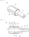
- the guide wire 10 can be introduced from the opening portion 36 into the space portion 35 in a state where the first member 30 and the second member 31 are disposed such that the opening portion 36 is continuous through the entire length as shown in Fig. 1 .
- the first member 30 has an outer peripheral surface 40 facing the outside and an inner peripheral surface 41 facing the space portion 35.
- the inner peripheral surface 41 is formed with an inner peripheral screw surface 42 that is a screw thread for screwing the second member 31.
- the first member 30 includes a tubular diameter decreasing portion 45 on an end portion in the space portion 35.
- the diameter decreasing portion 45 is made of an elastic material such as rubber.
- An outer peripheral surface 46 of the diameter decreasing portion 45 is abutted against the inner peripheral surface 41 of the first member 30.
- an inner peripheral surface 47 of the diameter decreasing portion 45 has a diameter larger than that of the guide wire 10, and the guide wire 10 can be inserted in a state shown in Figs. 1 and 2 .
- the diameter decreasing portion 45 Similar to the first member 30 and the second member 31, the diameter decreasing portion 45 has an opening portion through the entire length at one part in a circumferential direction (not shown), and the guide wire 10 can be inserted in the radial direction.
- the second member 31 has an outer peripheral surface 50 having a diameter that substantially matches an inner diameter of the first member 30. An outer diameter of the second member 31 on an end portion side exposed from the first member 30 is smaller than that of the outer peripheral surface 50 in the first member 30.
- the outer peripheral surface 50 of the second member 31 has an outer peripheral screw surface 51 screwed to the inner peripheral screw surface 42 of the first member 30.
- the second member 31 is formed with a tapered surface portion 54 at an end portion in the first member 30.
- the tapered surface portion 54 has an inner diameter increasing toward an end surface side.
- the tapered surface portion 54 is abutted against a pressing surface portion 48 that is an end portion outer peripheral surface of the diameter decreasing portion 45.
- the pressing surface portion 48 of the diameter decreasing portion 45 is inclined in the same direction as the tapered surface portion 54, and is pressed toward an inner peripheral side by the tapered surface portion 54 when the pressing surface portion 48 moves in the length direction of the guide wire 10.
- the guide wire 10 is held by the diameter decreasing portion 45. Accordingly, the guide wire 10 is fixed in the length direction and the radial direction with respect to the torque device 20, and the operator can move the guide wire 10 forward and backward and can rotate the guide wire 10 via the torque device 20.
- a positional relationship between the first member 30 and the second member 31 is set to the state shown in Fig. 2 in advance.
- the opening portion 36 is continuous over the first member 30 and the second member 31 as shown in Fig. 1 , and the guide wire 10 can be inserted into the space portion 35 through the opening portion 36.
- a position of the torque device 20 in the length direction of the guide wire 10 is adjusted.
- the first member 30 and the second member 31 are rotated relative to each other into a state shown in Fig. 4 . Accordingly, the guide wire 10 of the space portion 35 is held by the diameter decreasing portion 45.
- the guide wire 10 can be moved forward and backward and rotated via the torque device 20.
- the first member 30 and the second member 31 are rotated relative to each other to change from the state of Fig. 4 to the state of Fig. 2 . Accordingly, a state of the diameter decreasing portion 45 of holding the guide wire 10 is released, and the guide wire 10 can be removed from the space portion 35 to the outside through the opening portion 36.
- the guide wire 10 can be inserted in the radial direction from the opening portion 36 which is continuous over the first member 30 and the second member 31, and the inserted guide wire 10 can be held by the diameter decreasing portion 45 by rotating the first member 30 and the second member 31 relative to each other. Therefore, the guide wire 10 can be easily attached. Since the first member 30 and the second member 31 constituting the torque device 20 are rotary bodies, the torque device 20 holding the guide wire 10 can be easily rotated.
- a torque device 60 of the second embodiment includes a first member 70 and a second member 71 that are rotatable relative to each other and a space portion 75 inside the torque device 60.
- the space portion 75 is continuous through the first member 70 and the second member 71.
- the guide wire 10 can be inserted through the space portion 75.
- the torque device 60 is formed with an opening portion (not shown) continuous over the first member 70 and the second member 71.
- the opening portion connects the space portion 75 and the outside in the radial direction as in the first embodiment.
- the cylindrical first member 70 has an outer peripheral surface 80 and an inner peripheral surface 81, and a part of the inner peripheral surface 81 is formed by an inner peripheral member 82.
- the inner peripheral member 82 is formed of an elastic material such as rubber, and an inner peripheral surface 82a constitutes a part of a peripheral surface of the space portion 75.
- One end portion of the inner peripheral member 82 in the length direction is a fixed portion 82b fixed to the first member 70, and the other end portion of the inner peripheral member 82 in the length direction is a pressure contact portion 82c that is in pressure contact with the second member 71.
- the inner peripheral member 82 is provided with a hard portion 82d in pressure contact with an inner peripheral member 92 provided on the second member 71.
- the inner peripheral member 82 is made of an elastic and soft material, and the hard portion 82d is made of a hard material.
- the second member 71 has an outer peripheral surface 90 and an inner peripheral surface 91, and a part of the inner peripheral surface 91 is formed by the inner peripheral member 92.
- the inner peripheral member 92 is formed of an elastic material such as rubber like the inner peripheral member 82 of the first member 70, and an inner peripheral surface 92a constitutes a part of the peripheral surface of the space portion 75.
- One end portion of the inner peripheral member 92 in the length direction is a fixed portion 92b fixed to the second member 71, and the other end portion of the inner peripheral member 92 in the length direction is a pressure contact portion 92c that is in pressure contact with the hard portion 82c provided on the inner peripheral member 82 of the first member 70.
- the first member 70 and the second member 71 can rotate relative to each other via a rotation latch section 76.
- the rotation latch section 76 includes a gear portion 76a formed on the first member 70 and a claw portion 76b provided on the second member 71.
- the claw portion 76b is attached to the second member 71 via an biasing portion 76c such as a spring, and the claw portion 76b is biased in a direction of being pressed against the gear portion 76a.
- the gear portion 76a includes saw blade-shaped uneven portions along a circumferential direction, and each uneven portion has a surface inclined along the circumferential direction and a surface substantially along the radial direction.
- the claw portion 76b has an acute-angled tip portion, and one side thereof is substantially along the radial direction. Therefore, when the first member 70 rotates with respect to the second member 71 in a direction of an arrow in Fig. 6 , the claw portion 76b can ride on the inclined surface of the gear portion 76a. When the first member 70 tries to rotate with respect to the second member 71 in a direction opposite to the arrow in Fig. 6 , the side of the claw portion 76b that is substantially along the radial direction is abutted against a surface substantially along the radial direction of the gear portion 76a, and therefore, the first member 70 cannot rotate. Accordingly, the first member 70 can rotate only in one direction with respect to the second member 71 and the rotation state can be maintained.
- the first member 70 and the second member 71 are provided with the inner peripheral members 82, 92 whose both end portions in the length direction are restrained, respectively, and the first member 70 and the second member 71 are rotated relative to each other. Therefore, the guide wire 10 can be easily held by the rotary operation by twisting the inner peripheral members 82, 92 to decrease the diameter of the inner peripheral surfaces 82a, 92a.
- an inner peripheral member 83 of the first member 70 has the pressure contact portion 82c that is in pressure contact with the second member 71 at an outer peripheral portion.
- an inner peripheral surface 83a of the inner peripheral member 83 includes a protruding portion 83d that enters toward the second member 71.
- the protruding portion 83d enlarges the inner peripheral surface 83a of the inner peripheral member 83 to the inner peripheral surface 91 of the second member 71.
- a tip portion of the protruding portion 83d is a second pressure contact portion 83e that is in pressure contact with the second member 71.
- the inner peripheral member 83 provided on the first member 70 may have the inner peripheral surface 83a extending over the first member 70 and the second member 71.
- the inner peripheral member 83 is provided on the first member 70, and an inner peripheral member may be provided on the second member 71 such that an inner peripheral surface thereof enters the first member 70.
- the torque device 20 that holds the elongated body 10 includes: the first member 30 and the second member 31 that define the continuous space portion 35 through which the elongated body 10 is inserted along the length direction.
- the first member 30 and the second member 31 are rotatable relative to each other while holding the elongated body 10, and have the opening portion 36 that connects the space portion 35 and the outside in the radial direction.
- the opening portion 36 is continuous in the length direction of the first member 30 and the second member 31, and has the width through which the elongated body 10 is insertable.
- At least one of the first member 30 and the second member 31 includes the diameter decreasing portion 45 that decreases the diameter of the space portion 35 by the first member 30 and the second member 31 rotating relative to each other.
- the torque device 20 can easily guide the elongated body 10 from the opening portion 36 to the space portion 35, and can hold the elongated body 10 disposed in the space portion 35 by the first member 30 and the second member 31 rotating relative to each other, and therefore, the elongated body 10 can be easily attached and held. Further, the elongated body 10 attached and held by the torque device 20 can be moved forward and backward and rotated, and the operability can be improved.
- first member 30 and the second member 31 may move along the length direction of the elongated body 10 by rotating relative to each other, and the diameter decreasing portion 45 of one of the first member 30 and the second member 31 may be decreased in diameter by the other one of the first member 30 and the second member 31 moving along the length direction of the elongated body 10. Accordingly, it is possible to form a structure in which the diameter decreasing portion 45 is decreased with a simple structure of forming a screw surface on the first member 30 and the second member 31.
- the diameter decreasing portion 45 may be elastically deformable in the radial direction, and may have the pressing surface portion 48 that is pressed in the radial direction by the other one of the first member 30 and the second member 31 when the first member 30 and the second member 31 move along the length direction of the elongated body 10 by rotating relative to each other. Accordingly, the elongated body 10 can be elastically held by the diameter decreasing portion 45, and the operability of the held elongated body 10 can be further improved.
- first member 70 and the second member 71 may have the elastically deformable inner peripheral member 82 that is in pressure contact with or joined to the other one of the first member 70 and the second member 71, and the inner peripheral member 82 may have the inner peripheral surface 82a that constitutes at least a part of the peripheral surface of the space portion 75 to form the diameter decreasing portion. Accordingly, by the first member 70 and the second member 71 rotating relative to each other, it is possible to form a structure in which the inner peripheral member 82 is twisted to decrease the diameter.
- the inner peripheral member 83 provided on one of the first member 70 and the second member 71 may have the protruding portion 83d that enters the other one of the first member 70 and the second member 71. Accordingly, the inner peripheral surface 83a of the inner peripheral member 83 can be enlarged and the elongated body 10 can be held more firmly.
- the opening portion 36 may be continuous in the length direction of the elongated body 10 over the first member 30 and the second member 31 in a state where the diameter decreasing portion 45 is enlarged. Accordingly, the elongated body 10 can be easily inserted into the space portion 35 through the opening portion 36.
- the elongated body is the guide wire 10.
- the elongated body is not limited to the guide wire 10 as long as the elongated body is a member that is long in the length direction and is operated to move forward and backward and rotate and can withstand a pressure of the diameter decreasing portion 45.
- first member 30 of the torque device 20 shown in Fig. 1 has a nut-shaped outer peripheral surface, and may have an outer peripheral surface having a shape other than the above shape as long as the first member 30 has a shape that is easy to operate.
- the guide wire 10 is attached to the torque device 20 via the opening portion 36, and the guide wire 10 may be attached to the torque device 20 in advance.
- the first member 30 and the second member 31 are rotated to hold the guide wire 10, and the guide wire 10 is operated via the torque device 20.
- the inner peripheral surfaces 82a, 92a of the inner peripheral members 82, 92 are smooth surfaces, and protruding portions and uneven portions may be provided to make it easier to hold the guide wire 10.
Landscapes
- Health & Medical Sciences (AREA)
- Life Sciences & Earth Sciences (AREA)
- Biophysics (AREA)
- Pulmonology (AREA)
- Engineering & Computer Science (AREA)
- Anesthesiology (AREA)
- Biomedical Technology (AREA)
- Heart & Thoracic Surgery (AREA)
- Hematology (AREA)
- Animal Behavior & Ethology (AREA)
- General Health & Medical Sciences (AREA)
- Public Health (AREA)
- Veterinary Medicine (AREA)
- Media Introduction/Drainage Providing Device (AREA)
Abstract
Description
- The present invention relates to a torque device that improves the operability of an elongated body such as a guide wire inserted into a living body.
- When a catheter is inserted into a biological lumen, a guide wire is used as an elongated body that guides the catheter to a target site in the biological lumen. The guide wire is inserted along an axial direction of the catheter, and is inserted into the biological lumen prior to the catheter to guide the insertion of the catheter. The guide wire is also used to guide an endoscope. Since the biological lumen is bent and branched, it is necessary to move the guide wire forward and backward and rotate the guide wire when inserting the guide wire into the biological lumen.
- Since the guide wire has a small diameter as it is, it is difficult to hold and operate the guide wire. Therefore, there is known a torque device attached to a hand portion of the guide wire to facilitate operation. Examples of the torque device include those described in PTL 1.
- PTL 1:
JP-A-2011-62522 - It is desirable that the torque device is easy to attach to the guide wire and has good manual operability, and a torque device that has both of these is desired.
- The invention has been made to solve the above-described problems, and an object of the invention is to provide a torque device that can be easily attached to an elongated body such as a guide wire and has good manual operability.
- A torque device that holds an elongated body according to the invention that achieves the above object includes:
- a first member and a second member that define a continuous space portion through which the elongated body is inserted along a length direction, in which
- the first member and the second member are rotatable relative to each other while holding the elongated body, and have an opening portion that connects the space portion and outside in a radial direction,
- the opening portion is continuous in a length direction of the first member and the second member, and has a width through which the elongated body is insertable, and
- at least one of the first member and the second member includes a diameter decreasing portion that decreases a diameter of the space portion by the first member and the second member rotating relative to each other.
- The torque device configured as described above can easily guide the elongated body from the opening portion to the space portion, and can hold the elongated body disposed in the space portion by the first member and the second member rotating relative to each other, and therefore, the elongated body can be easily attached and held. Further, the elongated body attached and held by the torque device can be moved forward and backward and rotated, and the operability can be improved.
- The first member and the second member may move along the length direction of the elongated body by rotating relative to each other, and the diameter decreasing portion of one of the first member and the second member may be decreased in diameter by the other one of the first member and the second member moving along the length direction of the elongated body. Accordingly, it is possible to form a structure in which the diameter decreasing portion is decreased with a simple structure of forming a screw surface on the first member and the second member.
- The diameter decreasing portion may be elastically deformable in the radial direction, and may have a pressing surface portion that is pressed in the radial direction by the other one of the first member and the second member when the first member and the second member move along the length direction of the elongated body by rotating relative to each other. Accordingly, the elongated body can be elastically held by the diameter decreasing portion, and the operability of the held elongated body can be further improved.
- At least one of the first member and the second member may have an elastically deformable inner peripheral member that is in pressure contact with or joined to the other one of the first member and the second member, and the inner peripheral member may have an inner peripheral surface that constitutes at least a part of a peripheral surface of the space portion to form the diameter decreasing portion. Accordingly, by the first member and the second member rotating relative to each other, it is possible to form a structure in which the inner peripheral member is twisted to decrease the diameter.
- The inner peripheral member provided on one of the first member and the second member may include a protruding portion that enters the other one of the first member and the second member. Accordingly, the inner peripheral surface of the inner peripheral member can be enlarged, and the elongated body can be held more firmly.
- The opening portion may be continuous in the length direction of the elongated body over the first member and the second member in a state where the diameter decreasing portion is enlarged. Accordingly, the elongated body can be easily inserted into the space portion through the opening portion.
-
- [
Fig. 1] Fig. 1 is a perspective view of a torque device according to a first embodiment. - [
Fig. 2] Fig. 2 is a cross-sectional view of the torque device ofFig. 1 . - [
Fig. 3] Fig. 3 is a cross-sectional view of the torque device in a state where a diameter of a diameter decreasing portion is decreased. - [
Fig. 4] Fig. 4 is a cross-sectional view of the torque device in a state where a guide wire is held by the diameter decreasing portion. - [
Fig. 5] Fig. 5 is a cross-sectional view of a torque device according to a second embodiment. - [
Fig. 6] Fig. 6 is a cross-sectional view of a torque device in a state where a diameter of a diameter decreasing portion ofFig. 5 is decreased. - [
Fig. 7] Fig. 7 is an enlarged cross-sectional view of a part of a rotation latch mechanism. - [
Fig. 8] Fig. 8 is a cross-sectional view of a torque device according to a third embodiment. - Embodiments of the invention will be described below with reference to the drawings. Note that dimensional ratios in the drawings may be exaggerated for convenience of description and may differ from the actual ratios.
- A
torque device 20 according to an embodiment of the invention is attached to a hand portion of aguide wire 10 to be inserted into a biological lumen to improve the operability of theguide wire 10 by an operator. - As shown in
Fig. 1 , thetorque device 20 of the present embodiment includes afirst member 30 and asecond member 31 integrated with each other. Further, thetorque device 20 is formed with acontinuous space portion 35 through the entire length. Theguide wire 10 can be inserted through thespace portion 35 in a state where the first member 39 and thesecond member 31 are integrated. In addition, thetorque device 20 has anopening portion 36 through the entire length. Theopening portion 36 connects thespace portion 35 and the outside in a radial direction. Theopening portion 36 has a width for theguide wire 10 to be inserted into thespace portion 35 from the outside. - The
first member 30 and thesecond member 31 are rotatable relative to each other and move relative to each other along a length direction with the rotation. By moving thefirst member 30 and thesecond member 31 relative to each other in the length direction, it is possible to hold theguide wire 10 inserted through thespace portion 35 to be described later. Theguide wire 10 can be introduced from theopening portion 36 into thespace portion 35 in a state where thefirst member 30 and thesecond member 31 are disposed such that theopening portion 36 is continuous through the entire length as shown inFig. 1 . - As shown in
Fig. 2 , thefirst member 30 has an outerperipheral surface 40 facing the outside and an innerperipheral surface 41 facing thespace portion 35. The innerperipheral surface 41 is formed with an innerperipheral screw surface 42 that is a screw thread for screwing thesecond member 31. - The
first member 30 includes a tubulardiameter decreasing portion 45 on an end portion in thespace portion 35. Thediameter decreasing portion 45 is made of an elastic material such as rubber. An outerperipheral surface 46 of thediameter decreasing portion 45 is abutted against the innerperipheral surface 41 of thefirst member 30. Further, an innerperipheral surface 47 of thediameter decreasing portion 45 has a diameter larger than that of theguide wire 10, and theguide wire 10 can be inserted in a state shown inFigs. 1 and 2 . Similar to thefirst member 30 and thesecond member 31, thediameter decreasing portion 45 has an opening portion through the entire length at one part in a circumferential direction (not shown), and theguide wire 10 can be inserted in the radial direction. - The
second member 31 has an outerperipheral surface 50 having a diameter that substantially matches an inner diameter of thefirst member 30. An outer diameter of thesecond member 31 on an end portion side exposed from thefirst member 30 is smaller than that of the outerperipheral surface 50 in thefirst member 30. The outerperipheral surface 50 of thesecond member 31 has an outerperipheral screw surface 51 screwed to the innerperipheral screw surface 42 of thefirst member 30. - The
second member 31 is formed with atapered surface portion 54 at an end portion in thefirst member 30. The taperedsurface portion 54 has an inner diameter increasing toward an end surface side. The taperedsurface portion 54 is abutted against apressing surface portion 48 that is an end portion outer peripheral surface of thediameter decreasing portion 45. Thepressing surface portion 48 of thediameter decreasing portion 45 is inclined in the same direction as thetapered surface portion 54, and is pressed toward an inner peripheral side by the taperedsurface portion 54 when thepressing surface portion 48 moves in the length direction of theguide wire 10. - As shown in
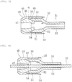
Fig. 3 , when thefirst member 30 and thesecond member 31 are rotated relative to each other and thesecond member 31 is moved in the length direction to enter the inside of thefirst member 30, thepressing surface portion 48 of thediameter decreasing portion 45 is pressed toward the inner peripheral side by the taperedsurface portion 54 of thesecond member 31. Accordingly, thediameter decreasing portion 45 is deformed toward the inner peripheral side, and the inner diameter becomes smaller. - As shown in
Fig. 4 , when thefirst member 30 and thesecond member 31 are rotated relative to each other in a state where theguide wire 10 is inserted, theguide wire 10 is held by thediameter decreasing portion 45. Accordingly, theguide wire 10 is fixed in the length direction and the radial direction with respect to thetorque device 20, and the operator can move theguide wire 10 forward and backward and can rotate theguide wire 10 via thetorque device 20. - When the
torque device 20 is used, a positional relationship between thefirst member 30 and thesecond member 31 is set to the state shown inFig. 2 in advance. In this state, the openingportion 36 is continuous over thefirst member 30 and thesecond member 31 as shown inFig. 1 , and theguide wire 10 can be inserted into thespace portion 35 through the openingportion 36. After theguide wire 10 is inserted into thespace portion 35, a position of thetorque device 20 in the length direction of theguide wire 10 is adjusted. After the position of thetorque device 20 is determined, thefirst member 30 and thesecond member 31 are rotated relative to each other into a state shown inFig. 4 . Accordingly, theguide wire 10 of thespace portion 35 is held by thediameter decreasing portion 45. When theguide wire 10 is held by thediameter decreasing portion 45, theguide wire 10 can be moved forward and backward and rotated via thetorque device 20. - When the
torque device 20 is removed from theguide wire 10, thefirst member 30 and thesecond member 31 are rotated relative to each other to change from the state ofFig. 4 to the state ofFig. 2 . Accordingly, a state of thediameter decreasing portion 45 of holding theguide wire 10 is released, and theguide wire 10 can be removed from thespace portion 35 to the outside through the openingportion 36. - As described above, in the
torque device 20 of the present embodiment, theguide wire 10 can be inserted in the radial direction from the openingportion 36 which is continuous over thefirst member 30 and thesecond member 31, and the insertedguide wire 10 can be held by thediameter decreasing portion 45 by rotating thefirst member 30 and thesecond member 31 relative to each other. Therefore, theguide wire 10 can be easily attached. Since thefirst member 30 and thesecond member 31 constituting thetorque device 20 are rotary bodies, thetorque device 20 holding theguide wire 10 can be easily rotated. - Next, a second embodiment of the invention will be described. As shown in
Fig. 5 , atorque device 60 of the second embodiment includes afirst member 70 and asecond member 71 that are rotatable relative to each other and aspace portion 75 inside thetorque device 60. Thespace portion 75 is continuous through thefirst member 70 and thesecond member 71. Theguide wire 10 can be inserted through thespace portion 75. - The
torque device 60 is formed with an opening portion (not shown) continuous over thefirst member 70 and thesecond member 71. The opening portion connects thespace portion 75 and the outside in the radial direction as in the first embodiment. - The cylindrical
first member 70 has an outerperipheral surface 80 and an innerperipheral surface 81, and a part of the innerperipheral surface 81 is formed by an innerperipheral member 82. The innerperipheral member 82 is formed of an elastic material such as rubber, and an innerperipheral surface 82a constitutes a part of a peripheral surface of thespace portion 75. One end portion of the innerperipheral member 82 in the length direction is a fixedportion 82b fixed to thefirst member 70, and the other end portion of the innerperipheral member 82 in the length direction is apressure contact portion 82c that is in pressure contact with thesecond member 71. Further, on an inner peripheral side relative to thepressure contact portion 82c, the innerperipheral member 82 is provided with ahard portion 82d in pressure contact with an innerperipheral member 92 provided on thesecond member 71. The innerperipheral member 82 is made of an elastic and soft material, and thehard portion 82d is made of a hard material. - The
second member 71 has an outerperipheral surface 90 and an innerperipheral surface 91, and a part of the innerperipheral surface 91 is formed by the innerperipheral member 92. The innerperipheral member 92 is formed of an elastic material such as rubber like the innerperipheral member 82 of thefirst member 70, and an innerperipheral surface 92a constitutes a part of the peripheral surface of thespace portion 75. One end portion of the innerperipheral member 92 in the length direction is a fixedportion 92b fixed to thesecond member 71, and the other end portion of the innerperipheral member 92 in the length direction is apressure contact portion 92c that is in pressure contact with thehard portion 82c provided on the innerperipheral member 82 of thefirst member 70. - The
first member 70 and thesecond member 71 can rotate relative to each other via arotation latch section 76. As shown inFig. 6 , therotation latch section 76 includes agear portion 76a formed on thefirst member 70 and aclaw portion 76b provided on thesecond member 71. Theclaw portion 76b is attached to thesecond member 71 via an biasingportion 76c such as a spring, and theclaw portion 76b is biased in a direction of being pressed against thegear portion 76a. Thegear portion 76a includes saw blade-shaped uneven portions along a circumferential direction, and each uneven portion has a surface inclined along the circumferential direction and a surface substantially along the radial direction. Theclaw portion 76b has an acute-angled tip portion, and one side thereof is substantially along the radial direction. Therefore, when thefirst member 70 rotates with respect to thesecond member 71 in a direction of an arrow inFig. 6 , theclaw portion 76b can ride on the inclined surface of thegear portion 76a. When thefirst member 70 tries to rotate with respect to thesecond member 71 in a direction opposite to the arrow inFig. 6 , the side of theclaw portion 76b that is substantially along the radial direction is abutted against a surface substantially along the radial direction of thegear portion 76a, and therefore, thefirst member 70 cannot rotate. Accordingly, thefirst member 70 can rotate only in one direction with respect to thesecond member 71 and the rotation state can be maintained. - When the
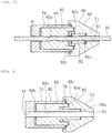
first member 70 and thesecond member 71 are rotated relative to each other, since both end portions of the innerperipheral member 82 of thefirst member 70 in the length direction are restrained correspondingly by the fixedportion 82b and thepressure contact portion 82c, twisting occurs along the length direction. Along with this, uneven portions are generated on the innerperipheral surface 82a of the innerperipheral member 82. Similarly, the innerperipheral member 92 of thesecond member 71 is twisted along the length direction, and uneven portions are generated on the innerperipheral surface 92a. Accordingly, as shown inFig. 7 , an inner diameter of thespace portion 75 is decreased, and theguide wire 10 inserted into thespace portion 75 can be held. That is, the innerperipheral members guide wire 10 is fixed in the length direction and the radial direction with respect to thetorque device 60, and the operator can move theguide wire 10 forward and backward, and can rotate theguide wire 10 via thetorque device 60. - Accordingly, the
first member 70 and thesecond member 71 are provided with the innerperipheral members first member 70 and thesecond member 71 are rotated relative to each other. Therefore, theguide wire 10 can be easily held by the rotary operation by twisting the innerperipheral members peripheral surfaces - Further, a configuration of the inner peripheral member is not limited thereto. As shown in
Fig. 8 , an innerperipheral member 83 of thefirst member 70 has thepressure contact portion 82c that is in pressure contact with thesecond member 71 at an outer peripheral portion. Further, an innerperipheral surface 83a of the innerperipheral member 83 includes a protrudingportion 83d that enters toward thesecond member 71. The protrudingportion 83d enlarges the innerperipheral surface 83a of the innerperipheral member 83 to the innerperipheral surface 91 of thesecond member 71. A tip portion of the protrudingportion 83d is a secondpressure contact portion 83e that is in pressure contact with thesecond member 71. Accordingly, the innerperipheral member 83 provided on thefirst member 70 may have the innerperipheral surface 83a extending over thefirst member 70 and thesecond member 71. InFig. 8 , the innerperipheral member 83 is provided on thefirst member 70, and an inner peripheral member may be provided on thesecond member 71 such that an inner peripheral surface thereof enters thefirst member 70. - As described above, the
torque device 20 according to the present embodiment that holds theelongated body 10 includes: thefirst member 30 and thesecond member 31 that define thecontinuous space portion 35 through which theelongated body 10 is inserted along the length direction. Thefirst member 30 and thesecond member 31 are rotatable relative to each other while holding theelongated body 10, and have the openingportion 36 that connects thespace portion 35 and the outside in the radial direction. The openingportion 36 is continuous in the length direction of thefirst member 30 and thesecond member 31, and has the width through which theelongated body 10 is insertable. At least one of thefirst member 30 and thesecond member 31 includes thediameter decreasing portion 45 that decreases the diameter of thespace portion 35 by thefirst member 30 and thesecond member 31 rotating relative to each other. Accordingly, thetorque device 20 according to the present embodiment can easily guide theelongated body 10 from the openingportion 36 to thespace portion 35, and can hold theelongated body 10 disposed in thespace portion 35 by thefirst member 30 and thesecond member 31 rotating relative to each other, and therefore, theelongated body 10 can be easily attached and held. Further, theelongated body 10 attached and held by thetorque device 20 can be moved forward and backward and rotated, and the operability can be improved. - Further, the
first member 30 and thesecond member 31 may move along the length direction of theelongated body 10 by rotating relative to each other, and thediameter decreasing portion 45 of one of thefirst member 30 and thesecond member 31 may be decreased in diameter by the other one of thefirst member 30 and thesecond member 31 moving along the length direction of theelongated body 10. Accordingly, it is possible to form a structure in which thediameter decreasing portion 45 is decreased with a simple structure of forming a screw surface on thefirst member 30 and thesecond member 31. - Further, the
diameter decreasing portion 45 may be elastically deformable in the radial direction, and may have thepressing surface portion 48 that is pressed in the radial direction by the other one of thefirst member 30 and thesecond member 31 when thefirst member 30 and thesecond member 31 move along the length direction of theelongated body 10 by rotating relative to each other. Accordingly, theelongated body 10 can be elastically held by thediameter decreasing portion 45, and the operability of the heldelongated body 10 can be further improved. - Further, at least one of the
first member 70 and thesecond member 71 may have the elastically deformable innerperipheral member 82 that is in pressure contact with or joined to the other one of thefirst member 70 and thesecond member 71, and the innerperipheral member 82 may have the innerperipheral surface 82a that constitutes at least a part of the peripheral surface of thespace portion 75 to form the diameter decreasing portion. Accordingly, by thefirst member 70 and thesecond member 71 rotating relative to each other, it is possible to form a structure in which the innerperipheral member 82 is twisted to decrease the diameter. - Further, the inner
peripheral member 83 provided on one of thefirst member 70 and thesecond member 71 may have the protrudingportion 83d that enters the other one of thefirst member 70 and thesecond member 71. Accordingly, the innerperipheral surface 83a of the innerperipheral member 83 can be enlarged and theelongated body 10 can be held more firmly. - Further, the opening
portion 36 may be continuous in the length direction of theelongated body 10 over thefirst member 30 and thesecond member 31 in a state where thediameter decreasing portion 45 is enlarged. Accordingly, theelongated body 10 can be easily inserted into thespace portion 35 through the openingportion 36. - Note that the invention is not limited to the embodiments described above and various modifications can be made by those skilled in the art within a scope of the technical idea of the invention. For example, in the above-described embodiment, the elongated body is the
guide wire 10. Alternatively, the elongated body is not limited to theguide wire 10 as long as the elongated body is a member that is long in the length direction and is operated to move forward and backward and rotate and can withstand a pressure of thediameter decreasing portion 45. - Further, the
first member 30 of thetorque device 20 shown inFig. 1 has a nut-shaped outer peripheral surface, and may have an outer peripheral surface having a shape other than the above shape as long as thefirst member 30 has a shape that is easy to operate. - Further, in the embodiments described above, the
guide wire 10 is attached to thetorque device 20 via the openingportion 36, and theguide wire 10 may be attached to thetorque device 20 in advance. In this case, after moving thetorque device 20 to any position in the length direction of theguide wire 10, thefirst member 30 and thesecond member 31 are rotated to hold theguide wire 10, and theguide wire 10 is operated via thetorque device 20. - Further, in the
torque device 60 of the second embodiment, the innerperipheral surfaces peripheral members guide wire 10. - This application is based on
Japanese Patent Application No. 2019-45466, filed on March 13, 2019 -
- 10:
- guide wire
- 20:
- torque device
- 30:
- first member
- 31:
- second member
- 35:
- space portion
- 36:
- opening portion
- 40:
- outer peripheral surface
- 41:
- inner peripheral surface
- 42:
- inner peripheral screw surface
- 45:
- diameter decreasing portion
- 46:
- outer peripheral surface
- 47:
- inner peripheral surface
- 48:
- pressing surface portion
- 50:
- outer peripheral surface
- 51:
- outer peripheral screw surface
- 52:
- inner peripheral surface
- 54:
- tapered surface portion
- 70:
- first member
- 71:
- second member
- 75:
- space portion
- 76:
- rotation latch section
- 80:
- outer peripheral surface
- 81:
- inner peripheral surface
- 82:
- inner peripheral member
- 82a:
- inner peripheral surface
- 82b:
- fixed portion
- 82c:
- pressure contact portion
- 82d:
- hard portion
- 84:
- slope surface portion
- 90:
- outer peripheral surface
- 91:
- inner peripheral surface
- 92:
- inner peripheral member
Claims (6)
- A torque device that holds an elongated body, the torque device comprising:a first member and a second member that define a continuous space portion through which the elongated body is inserted along a length direction, whereinthe first member and the second member are rotatable relative to each other while holding the elongated body, and have an opening portion that connects the space portion and outside in a radial direction,the opening portion is continuous in a length direction of the first member and the second member, and has a width through which the elongated body is insertable, andat least one of the first member and the second member includes a diameter decreasing portion that decreases a diameter of the space portion by the first member and the second member rotating relative to each other.
- The torque device according to claim 1, whereinthe first member and the second member move along the length direction of the elongated body by rotating relative to each other, andthe diameter decreasing portion of one of the first member and the second member is decreased in diameter by the other one of the first member and the second member moving along the length direction of the elongated body.
- The torque device according to claim 2, wherein
the diameter decreasing portion is elastically deformable in the radial direction, and has a pressing surface portion that is pressed in the radial direction by the other one of the first member and the second member when the first member and the second member move along the length direction of the elongated body by rotating relative to each other. - The torque device according to claim 1, wherein
at least one of the first member and the second member has an elastically deformable inner peripheral member that is in pressure contact with or joined to the other one of the first member and the second member, and the inner peripheral member has an inner peripheral surface that constitutes at least a part of a peripheral surface of the space portion to form the diameter decreasing portion. - The torque device according to claim 4, wherein
the inner peripheral member provided on one of the first member and the second member includes a protruding portion that enters the other one of the first member and the second member. - The torque device according to any one of claims 1 to 5, wherein
the opening portion is continuous in the length direction of the elongated body over the first member and the second member in a state where the diameter decreasing portion is enlarged.
Applications Claiming Priority (2)
| Application Number | Priority Date | Filing Date | Title |
|---|---|---|---|
| JP2019045466 | 2019-03-13 | ||
| PCT/JP2020/009969 WO2020184507A1 (en) | 2019-03-13 | 2020-03-09 | Torque device |
Publications (2)
| Publication Number | Publication Date |
|---|---|
| EP3932461A1 true EP3932461A1 (en) | 2022-01-05 |
| EP3932461A4 EP3932461A4 (en) | 2022-05-18 |
Family
ID=72427571
Family Applications (1)
| Application Number | Title | Priority Date | Filing Date |
|---|---|---|---|
| EP20770294.5A Pending EP3932461A4 (en) | 2019-03-13 | 2020-03-09 | TORQUE DEVICE |
Country Status (4)
| Country | Link |
|---|---|
| US (1) | US20210299413A1 (en) |
| EP (1) | EP3932461A4 (en) |
| JP (1) | JPWO2020184507A1 (en) |
| WO (1) | WO2020184507A1 (en) |
Families Citing this family (2)
| Publication number | Priority date | Publication date | Assignee | Title |
|---|---|---|---|---|
| JP7540894B2 (en) * | 2020-03-18 | 2024-08-27 | 朝日インテック株式会社 | Torque transmission tool |
| WO2025203975A1 (en) * | 2024-03-29 | 2025-10-02 | 朝日インテック株式会社 | Occlusion device and medical connector equipped with said occlusion device |
Family Cites Families (8)
| Publication number | Priority date | Publication date | Assignee | Title |
|---|---|---|---|---|
| EP1727586A2 (en) * | 2004-03-24 | 2006-12-06 | Windcrest LLC | Vascular guidewire control apparatus |
| US20050240120A1 (en) * | 2004-04-26 | 2005-10-27 | Modesitt D B | Vise and method of use |
| US20070016105A1 (en) * | 2005-06-27 | 2007-01-18 | Mamourian Alexander C | Wire torque apparatus, wire insertion devices, improved aneurysm clips and improved aneurysm clip applicators |
| US20130103001A1 (en) * | 2011-10-19 | 2013-04-25 | Imds Corporation | Side-Loading Torque Device |
| JP5928064B2 (en) * | 2012-03-27 | 2016-06-01 | 株式会社カネカ | MEDICAL DEVICE VALVE, MEDICAL DEVICE, AND METHOD FOR MANUFACTURING MEDICAL DEVICE VALVE |
| WO2015021009A1 (en) * | 2013-08-05 | 2015-02-12 | Vascular Imaging Corporation | Guidewire torque handle |
| US9642640B2 (en) * | 2014-08-04 | 2017-05-09 | Gyrus Acmi, Inc. | Lithotripter with improved sterilization time |
| JP7134644B2 (en) | 2017-09-04 | 2022-09-12 | 日清オイリオグループ株式会社 | Determination method of dialkyl ketone in fats and oils |
-
2020
- 2020-03-09 WO PCT/JP2020/009969 patent/WO2020184507A1/en not_active Ceased
- 2020-03-09 JP JP2021505059A patent/JPWO2020184507A1/ja active Pending
- 2020-03-09 EP EP20770294.5A patent/EP3932461A4/en active Pending
-
2021
- 2021-06-14 US US17/346,720 patent/US20210299413A1/en not_active Abandoned
Also Published As
| Publication number | Publication date |
|---|---|
| WO2020184507A1 (en) | 2020-09-17 |
| US20210299413A1 (en) | 2021-09-30 |
| EP3932461A4 (en) | 2022-05-18 |
| JPWO2020184507A1 (en) | 2020-09-17 |
Similar Documents
| Publication | Publication Date | Title |
|---|---|---|
| JP4716513B2 (en) | Endoscopic clip device | |
| JP3634644B2 (en) | Endoscope operation part | |
| EP2065003A2 (en) | Endoscope treatment system | |
| JPS61181453A (en) | Stone crushing apparatus | |
| JP2022000243A5 (en) | ||
| US10653303B2 (en) | Endoscope and hardness adjustment device | |
| JP6099837B2 (en) | Endoscopic treatment tool | |
| JP4669090B2 (en) | Treatment tool | |
| US8414574B2 (en) | Treatment instrument having a front-end treatment member | |
| US20210299413A1 (en) | Torque device | |
| US6093155A (en) | Cytologic brush for endoscope | |
| KR102165477B1 (en) | Endoscopy needle | |
| JP5174528B2 (en) | Endoscope operation part | |
| JP5137758B2 (en) | Bipolar high-frequency treatment instrument for endoscope | |
| JP5191364B2 (en) | Endoscopic treatment tool | |
| JP4589664B2 (en) | Endoscope treatment device raising device | |
| JP4441509B2 (en) | Endoscopic treatment tool | |
| JP2008104831A (en) | Cardiac catheter | |
| US20060234184A1 (en) | Dental device | |
| JP4877547B2 (en) | Cardiac catheter | |
| JP2007283080A (en) | Endoscope clip | |
| JPH0521913U (en) | Intracorporeal treatment tool | |
| JP2000166863A (en) | Endoscope puncture device | |
| WO2021090544A1 (en) | Medical device kit and medical tubular member | |
| JP2010082298A (en) | Bipolar high-frequency snare for endoscope |
Legal Events
| Date | Code | Title | Description |
|---|---|---|---|
| STAA | Information on the status of an ep patent application or granted ep patent |
Free format text: STATUS: THE INTERNATIONAL PUBLICATION HAS BEEN MADE |
|
| PUAI | Public reference made under article 153(3) epc to a published international application that has entered the european phase |
Free format text: ORIGINAL CODE: 0009012 |
|
| STAA | Information on the status of an ep patent application or granted ep patent |
Free format text: STATUS: REQUEST FOR EXAMINATION WAS MADE |
|
| 17P | Request for examination filed |
Effective date: 20210930 |
|
| AK | Designated contracting states |
Kind code of ref document: A1 Designated state(s): AL AT BE BG CH CY CZ DE DK EE ES FI FR GB GR HR HU IE IS IT LI LT LU LV MC MK MT NL NO PL PT RO RS SE SI SK SM TR |
|
| A4 | Supplementary search report drawn up and despatched |
Effective date: 20220419 |
|
| RIC1 | Information provided on ipc code assigned before grant |
Ipc: A61B 17/00 20060101ALN20220411BHEP Ipc: A61M 25/09 20060101AFI20220411BHEP |
|
| DAV | Request for validation of the european patent (deleted) | ||
| DAX | Request for extension of the european patent (deleted) | ||
| STAA | Information on the status of an ep patent application or granted ep patent |
Free format text: STATUS: EXAMINATION IS IN PROGRESS |
|
| 17Q | First examination report despatched |
Effective date: 20250530 |