EP3932443A1 - Tube winding bobbin and blood bag system - Google Patents
Tube winding bobbin and blood bag system Download PDFInfo
- Publication number
- EP3932443A1 EP3932443A1 EP20770432.1A EP20770432A EP3932443A1 EP 3932443 A1 EP3932443 A1 EP 3932443A1 EP 20770432 A EP20770432 A EP 20770432A EP 3932443 A1 EP3932443 A1 EP 3932443A1
- Authority
- EP
- European Patent Office
- Prior art keywords
- tube
- winding bobbin
- blood
- winding
- Prior art date
- Legal status (The legal status is an assumption and is not a legal conclusion. Google has not performed a legal analysis and makes no representation as to the accuracy of the status listed.)
- Withdrawn
Links
- 238000004804 winding Methods 0.000 title claims abstract description 170
- 210000004369 blood Anatomy 0.000 title claims abstract description 138
- 239000008280 blood Substances 0.000 title claims abstract description 138
- 238000005119 centrifugation Methods 0.000 claims abstract description 50
- 230000008878 coupling Effects 0.000 claims description 13
- 238000010168 coupling process Methods 0.000 claims description 13
- 238000005859 coupling reaction Methods 0.000 claims description 13
- 210000000078 claw Anatomy 0.000 claims description 11
- 239000008155 medical solution Substances 0.000 description 21
- 238000000926 separation method Methods 0.000 description 14
- 210000003743 erythrocyte Anatomy 0.000 description 11
- 239000012503 blood component Substances 0.000 description 9
- 238000012986 modification Methods 0.000 description 8
- 230000004048 modification Effects 0.000 description 8
- 238000010241 blood sampling Methods 0.000 description 7
- 230000000694 effects Effects 0.000 description 5
- 238000003780 insertion Methods 0.000 description 5
- 230000037431 insertion Effects 0.000 description 5
- 210000000265 leukocyte Anatomy 0.000 description 5
- 238000007789 sealing Methods 0.000 description 5
- 239000003761 preservation solution Substances 0.000 description 4
- 239000000306 component Substances 0.000 description 3
- 230000005484 gravity Effects 0.000 description 3
- 238000004519 manufacturing process Methods 0.000 description 3
- 230000015572 biosynthetic process Effects 0.000 description 2
- 239000010836 blood and blood product Substances 0.000 description 2
- 229940125691 blood product Drugs 0.000 description 2
- 239000000470 constituent Substances 0.000 description 2
- 230000002093 peripheral effect Effects 0.000 description 2
- 239000000243 solution Substances 0.000 description 2
- 230000004308 accommodation Effects 0.000 description 1
- 239000007788 liquid Substances 0.000 description 1
- 238000000034 method Methods 0.000 description 1
- 230000003287 optical effect Effects 0.000 description 1
Images





Classifications
-
- A—HUMAN NECESSITIES
- A61—MEDICAL OR VETERINARY SCIENCE; HYGIENE
- A61M—DEVICES FOR INTRODUCING MEDIA INTO, OR ONTO, THE BODY; DEVICES FOR TRANSDUCING BODY MEDIA OR FOR TAKING MEDIA FROM THE BODY; DEVICES FOR PRODUCING OR ENDING SLEEP OR STUPOR
- A61M1/00—Suction or pumping devices for medical purposes; Devices for carrying-off, for treatment of, or for carrying-over, body-liquids; Drainage systems
- A61M1/02—Blood transfusion apparatus
- A61M1/0209—Multiple bag systems for separating or storing blood components
-
- A—HUMAN NECESSITIES
- A61—MEDICAL OR VETERINARY SCIENCE; HYGIENE
- A61M—DEVICES FOR INTRODUCING MEDIA INTO, OR ONTO, THE BODY; DEVICES FOR TRANSDUCING BODY MEDIA OR FOR TAKING MEDIA FROM THE BODY; DEVICES FOR PRODUCING OR ENDING SLEEP OR STUPOR
- A61M1/00—Suction or pumping devices for medical purposes; Devices for carrying-off, for treatment of, or for carrying-over, body-liquids; Drainage systems
- A61M1/02—Blood transfusion apparatus
- A61M1/0272—Apparatus for treatment of blood or blood constituents prior to or for conservation, e.g. freezing, drying or centrifuging
- A61M1/0277—Frames constraining or supporting bags, e.g. during freezing
Definitions
- the present invention relates to a tube winding bobbin used when a blood bag system is set in a centrifugation transfer device, and a blood bag system to which the tube winding bobbin is applied.
- a blood bag system including a blood bag that stores blood is set in a centrifugation transfer device.
- the centrifugation transfer device applies a centrifugal force to the set blood bag to separate the blood in the blood bag into a plurality of types of blood components, and transfers a predetermined blood component to another bag via a tube connected to the blood bag.
- the blood of a donor is transferred to the blood bag via the tube and, then, a plurality of points of the tube connected to the blood bag is sealed.
- a segment tube is formed (see JP 2016-171967 A ).
- the segment tube independently includes a plurality of sealed tubes in which blood is contained.
- the centrifugation transfer device includes a segment pocket that accommodates the segment tube such that the segment tube of the blood bag system does not interfere with the centrifugation transfer device during centrifugation.
- the user may take time to accommodate the plurality of sealed tubes in the segment pocket, and the plurality of sealed tubes may stick out of the segment pocket depending on an accommodation state.
- the present invention has been made in view of the above circumstances, and an object of the present invention is to provide a tube winding bobbin and a blood bag system capable of improving work efficiency by easily accommodating a plurality of sealed tubes and preventing the plurality of sealed tubes from sticking out.
- a first aspect of the present invention is a tube winding bobbin attachable to a centrifugation transfer device in which a blood bag system is set, in which the blood bag system includes a tube member including a plurality of sealed tubes, the plurality of sealed tubes extending for a predetermined length and having a closed lumen therein, the tube winding bobbin includes a winding part around which the tube member is wound, and a pair of side parts coupled to both ends of the winding part and protruding in a thickness direction of the winding part, and the winding part has a length that is set such that the tube member is wound around the winding part in a state where the tube member is folded at a point of a coupling seal part that connects the plurality of sealed tubes to each other.
- a second aspect of the present invention is a blood bag system including a first bag configured to accommodate blood, a second bag configured to accommodate a predetermined component in the blood, and a tube connecting the first bag and the second bag, in which the tube is provided with a tube winding bobbin around which the tube can be wound, and the tube winding bobbin includes a winding part around which the tube is wound, and a pair of side parts coupled to both ends of the winding part and protruding in a thickness direction of the winding part.
- the plurality of sealed tubes can be accommodated in the pocket of the centrifugation transfer device in a state of being wound around the winding part of the tube winding bobbin.
- the plurality of sealed tubes is folded back without being disordered, and the plurality of sealed tubes can be smoothly inserted into the pocket.
- a tube winding bobbin 84 according to an embodiment of the present invention is set in a centrifugation transfer device 12 together with a blood bag system 10 by a user such as a medical worker.
- the centrifugation transfer device 12 centrifuges blood in the blood bag system 10 to generate and store a plurality of types of blood components.
- a configuration including the blood bag system 10 and the centrifugation transfer device 12 is referred to as a blood product manufacturing system 14.
- the blood bag system 10 includes a preprocessor 15 (see Fig. 4 ) used for blood collection before centrifugation, and a separation processor 16 that generates blood components by centrifugation and individually stores the blood components.
- the preprocessor 15 and the separation processor 16 are connected by a relay tube 18.
- the relay tube 18 connected to the preprocessor 15 is cut before centrifugation, and the separation processor 16 is in a state illustrated in Fig. 1 , and is set in the centrifugation transfer device 12.
- the preprocessor 15 of the blood bag system 10 collects whole blood from a donor and removes a predetermined blood component (for example, white blood cells) from the whole blood.
- the preprocessor 15 includes a blood sampling needle, a blood sampling bag 15a (first bag: see Fig. 4 ), an initial flow blood bag, a filter (for example, a white blood cell removal filter), and the like, and is configured by connecting each member by a plurality of tubes.
- the separation processor 16 is connected to downstream of the filter via the relay tube 18. Specifically, the preprocessor 15 stores initial blood of the whole blood of the donor collected through the blood sampling needle in the initial flow blood bag, and then stores residual blood in the blood sampling bag 15a. Furthermore, the preprocessor 15 removes white blood cells in the filter by causing the whole blood stored in the blood sampling bag 15a to flow to the filter, and transfers the removed blood (white blood cell removed blood) to the separation processor 16.
- the separation processor 16 of the blood bag system 10 includes a plurality of bags 20 (a blood bag 22, a PPP bag 24, and a medical solution bag 26), and is configured by connecting the bags 20 by a plurality of tubes 30.
- the blood bag 22 (second bag) is directly connected to the relay tube 18 connected to the preprocessor 15 in a state of the blood bag system 10 provided as a product.
- the blood bag 22 stores the removed blood transferred from the filter during blood collection.
- the blood bag 22 is set in the centrifugation transfer device 12, and a centrifugal force is applied by operation of the centrifugation transfer device 12.
- the removed blood in the blood bag 22 is centrifuged into blood components (platelet poor plasma (PPP) and red blood cells (RBC)) and the like having different specific gravities.
- PPP platelet poor plasma
- RBC red blood cells
- the PPP is supplied from the blood bag 22, and the PPP bag 24 stores the PPP.
- the medical solution bag 26 stores in advance a red blood cell preservation solution such as MAP solution, SAGM solution, or OPTISOL.
- a segment tube 28 is formed in the separation processor 16 after the removed blood is transferred to the blood bag 22 and before the separation processor 16 is set in the centrifugation transfer device 12.
- the segment tube 28 includes a plurality of sealed tubes 28a having a predetermined length and having a closed lumen. Donor blood (removed blood) is present in the lumen of each sealed tube 28a.
- the relay tube 18 connecting the blood bag 22 and the preprocessor 15 (filter) is cut near the filter and is further sealed at predetermined intervals, and thus the plurality of sealed tubes 28a is formed so as to be continuous in series.
- the segment tubes 28 are cut by the user as necessary and used for checking blood and the like.
- the plurality of tubes 30 of the separation processor 16 is branched into a plurality of tubes via a branch connector 32 (Y-shaped connector).
- the plurality of tubes 30 includes a first tube 34 connecting the blood bag 22 and the branch connector 32, a second tube 36 connecting the PPP bag 24 and the branch connector 32, and a third tube 38 connecting the medical solution bag 26 and the branch connector 32.
- the first tube 34 includes a first flow path 34a
- the second tube 36 includes a second flow path 36a
- the third tube 38 includes a third flow path 38a.
- the first to third flow paths 34a, 36a, and 38a communicate with each other via a flow path in the branch connector 32.
- a breakable sealing member 40 click tip is provided at an end of the first tube 34 closer to the blood bag 22.
- a breakable sealing member 42 is provided at an end of the third tube 38 closer to the medical solution bag 26.
- the sealing members 40 and 42 block the first flow path 34a and the third flow path 38a until breaking operation is performed, and prevent a liquid in the blood bag 22 and the medical solution bag 26 from being transferred to another bag 20.
- the centrifugation transfer device 12 in which the separation processor 16 of the blood bag system 10 is set includes a box-shaped base body 44, a lid 46 capable of opening and closing an upper surface of the base body 44, and a centrifugal drum 48 provided in the base body 44. Further, the base body 44 of the centrifugation transfer device 12 is provided with a motor (not illustrated) that rotates the centrifugal drum 48, a controller 50 that controls the operation of the centrifugation transfer device 12, and an operation display 52 for the user to confirm and operate.
- the centrifugal drum 48 has a plurality of (six) unit set areas 54 in which the separation processor 16 can be set.
- a height of one unit set area 54 is larger than a length of the bag 20 in a long-length direction, and is set in a range of 60° with respect to a rotation center of the centrifugal drum 48. That is, the six unit set areas 54 are arranged side by side without a gap along a circumferential direction to constitute the centrifugal drum 48 as an annular structure.
- each of the unit set areas 54 applies a centrifugal force to the blood bag 22 as the centrifugal drum 48 rotates.
- each of the unit set areas 54 includes a blood bag pocket 56 accommodating the blood bag 22, a PPP bag pocket 58 accommodating the PPP bag 24, and a medical solution bag pocket 60 accommodating the medical solution bag 26 radially outside of the centrifugal drum 48.
- the blood bag pocket 56 is provided at a circumferential center of the unit set area 54 and has a larger volume than the PPP bag pocket 58 and the medical solution bag pocket 60.
- the PPP bag pocket 58 and the medical solution bag pocket 60 are provided side by side in the circumferential direction radially outside of the blood bag pocket 56.
- An upper surface 54a of the unit set area 54 is configured to arrange and hold the plurality of tubes 30 of the blood bag system 10.
- a part of the first tube 34 and a part of the segment tube 28 are disposed in a central region 54a1 (first region) radially inside of the blood bag pocket 56 in the upper surface 54a.
- the central region 54a1 is provided with a top cover 62 that opens and closes an opening of the blood bag pocket 56.
- a sensor 66 optical sensor that detects a part of the breaker 64 breaking the sealing member 40 and a state of blood flowing through the first tube 34 is provided at an arrangement position of the first tube 34 closed by the top cover 62.
- a part of the first tube 34, a part of the branch connector 32, a part of the second tube 36, and a part of the third tube 38 that have passed through the central region 54a1 are disposed in a left region 54a2 (second region) of the upper surface 54a.
- the left region 54a2 is provided with a holder 68 that holds the branch connector 32, a PPP clamp 70 that opens and closes the second flow path 36a of the second tube 36, and a medical solution clamp 72 that opens and closes the third flow path 38a of the third tube 38.
- a part of the segment tube 28 that passes through the central region 54a1 is disposed in a right region 54a3 (third region) of the upper surface 54a.
- the right region 54a3 is provided with a segment pocket 74 that accommodates the plurality of sealed tubes 28a of the segment tube 28.
- a tube holder 76 that protruding upward of the upper surface 54a is provided radially outside of the PPP bag pocket 58 and the medical solution bag pocket 60 of the unit set area 54.
- the tube holder 76 has an outer wall 78 continuous with an outer peripheral edge of the unit set area 54 and an inner wall 80 protruding inward of the outer wall 78 from the outer peripheral edge, and the second tube 36 is disposed between the outer wall 78 and the inner wall 80.
- the inner wall 80 extends from near the PPP clamp 70 in the left region 54a2 (left side of the medical solution bag pocket 60) to a circumferential intermediate position of the PPP bag pocket 58, and guides the second tube 36 to the PPP bag pocket 58.
- the unit set area 54 includes a slider 82 (pusher) that presses the blood bag 22 after centrifugation radially inside of the blood bag pocket 56.
- a surface of the slider 82 facing the blood bag 22 is formed as an inclined surface 82a. The slider 82 moves forward and backward along a radial direction of the centrifugal drum 48 under control of the controller 50 (see Fig. 1 ).
- the user accommodates the blood bag 22 storing the removed blood in the blood bag pocket 56, the empty PPP bag 24 in the PPP bag pocket 58, and the medical solution bag 26 storing the medical solution in the medical solution bag pocket 60. Then, the unit set area 54 centrifuges the removed blood in the blood bag 22 by the rotation of the centrifugal drum 48, advances the slider 82 after the centrifugation, and presses the blood bag 22. As a result, PPP generated by centrifugation in the blood bag 22 is transferred to the PPP bag 24, and the RBC remains in the blood bag 22 after the transfer of PPP.
- the blood bag system 10 is taken out from the centrifugation transfer device 12 by the user, and the medical solution bag 26 is hung on a stand (not illustrated).
- the red blood cell preservation solution is supplied from the medical solution bag 26 to the blood bag 22, and the blood bag 22 is storing RBC (blood product) including a medical solution.
- the tube winding bobbin 84 is a member provided for the segment tube 28 of the blood bag system 10 to be wound around, and is accommodated in the segment pocket 74 of the centrifugation transfer device 12 (unit set area 54) in a state where the segment tube 28 is wound around. That is, the tube winding bobbin 84 is integrally accommodated with the segment tube 28 in the segment pocket 74, and this facilitates setting of the segment tube 28 in the centrifugation transfer device 12.
- the segment tube 28 has a plurality of (for example, seven to eight) sealed tubes 28a as described above.
- a coupling seal part 28b that is sealed by crushing the relay tube 18 is formed between the adjacent sealed tubes 28a.
- An extending length of each of the sealed tubes 28a is not limited, but is a dimension of, for example, about 6 cm to 8 cm.
- the segment tube 28 includes an elongated coupling tube 28c that connects the plurality of sealed tubes 28a and the blood bag 22.
- the coupling tube 28c extends on the upper surface 54a (the central region 54a1 and the right region 54a3) of the unit set area 54 and allows the plurality of sealed tubes 28a to reach the segment pocket 74.
- the tube winding bobbin 84 includes a winding part 86 around which the plurality of sealed tubes 28a is wound, and a pair of side parts 88 coupled to both ends of the winding part 86 in an extending direction.
- the winding part 86 and the pair of side parts 88 are integrally molded to be continuous in series.
- the winding part 86 has a rectangular plate shape, and the side parts 88 are coupled to the winding part 86 along a pair of long sides continuous to both ends in a short-length direction.
- the extending length along a long-length direction of the winding part 86 is slightly shorter than the extending length of the plurality of sealed tubes 28a.
- an extending length Lb (see Fig. 4 ) of the winding part 86 in the long-length direction is set in a range of 5 cm to 7.5 cm.
- a plate thickness of the winding part 86 is to be set to an appropriate thickness corresponding to ends of the adjacent sealed tubes 28a and the coupling seal parts 28b.
- a thickness of the winding part 86 is set to be in a range of about 5 mm to 20 mm.
- a plurality of guide notches 90 that guides arrangement of the segment tube 28 is provided on a pair of short sides (sides at both ends in the long-length direction) of the winding part 86.
- the plurality of guide notches 90 has a recessed shape (arc shape) in which the short sides are recessed inward, and a plurality of guide notches is arranged side by side along the short sides. A dimension along the short side of each guide notch 90 is set to match an outer diameter of the sealed tube 28a.
- the winding part 86 formed as described above can be wound around the winding part 86 while the plurality of sealed tubes 28a is folded at the coupling seal part 28b. That is, a body of each sealed tube 28a extends on one plate surface of the winding part 86, and both ends continuous with the body protrude from both ends of the winding part 86 in the long-length direction.
- the coupling seal part 28b connected to both ends easily reverses an extending direction of the segment tube 28 while being guided by an arbitrary guide notch 90, and the sealed tube 28a extends along the other plate surface of the winding part 86.
- the blood bag system 10 may be provided as a product as illustrated in Fig. 4 , including the tube winding bobbin 84.
- the tube winding bobbin 84 is provided on the relay tube 18 connecting the blood sampling bag 15a and the blood bag 22 storing blood, downstream of the filter (not illustrated) of the preprocessor 15.
- the tube winding bobbin 84 is provided together with the blood bag system 10 in a state where each of the pair of side parts 88 has an attachment hole 88a and the relay tube 18 is inserted through the pair of attachment hole 88a.
- the pair of attachment holes 88a is provided on one end of the pair of side parts 88 in one long-length direction and on the other end of the pair of side parts 88 in the other long-length direction.
- Each attachment hole 88a has an inner diameter having a margin to some extent with respect to an outer diameter of the relay tube 18. That is, the tube winding bobbin 84 is displaceable along an extending direction of the relay tube 18. As described above, the relay tube 18 is cut before the centrifugation transfer device 12 is set, and thus the tube winding bobbin 84 can be detached from a cut point of the relay tube 18. Therefore, in the tube winding bobbin 84, the plurality of sealed tubes 28a can be satisfactorily wound around the winding part 86 when the segment tube 28 is wound.
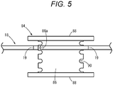
- a method of providing the tube winding bobbin 84 on the relay tube 18 is not limited, and for example, as illustrated in Fig. 5 , one attachment hole 86a may be provided on one side of the plate-shaped winding part 86 in the long-length direction.
- the attachment hole 86a is formed in a crest between two adjacent guide notches 90 near one side part 88.
- the relay tube 18 is provided as a product together with the blood bag system 10 while being movably inserted into the attachment hole 86a.
- the plurality of sealed tubes 28a can be wound around the winding part 86 with the relay tube 18 passing through the attachment hole 86a after the plurality of sealed tubes 28a is formed by a sealer (not illustrated).
- the tube winding bobbin 84 may be fixed to the relay tube 18 when the blood bag system 10 is provided as a product.
- the tube winding bobbin 84 is fixed to one end (for example, a vicinity of a cut point between the preprocessor 15 and the separation processor 16) of the plurality of sealed tubes 28a to be formed, and thus the plurality of sealed tubes 28a can be wound with this fixed position as a base point.
- the blood bag system 10 is preferably provided with a plurality of indicators 19 that guides formation of the sealed tube 28a in accordance with the tube winding bobbin 84.
- each indicator 19 is formed as a linear scale that goes around a surface of the relay tube 18 in a circumferential direction.
- An interval Lt between the adjacent indicators 19 of the indicators 19 is set to be slightly longer than the extending length Lb in the long-length direction of the winding part 86 of the tube winding bobbin 84.
- Each of the indicators 19 guides a sealed position by the user when the sealed tube 28a is formed to indirectly lead the formation of each sealed tube 28a having a length corresponding to the winding part 86. It is therefore preferable to set the interval Lt between the adjacent indicators 19 appropriately in consideration of a sealing range of the relay tube 18.
- the pair of side parts 88 of the tube winding bobbin 84 is a plate body extending along the long side of the winding part 86, and has a rectangular shape whose length in the long-length direction is longer than a length in the long-length direction of the winding part 86.
- a short-length direction of the pair of side parts 88 protrudes in a direction orthogonal to a surface direction of the winding part 86. That is, the tube winding bobbin 84 has an H-shape in plan view.
- the pair of side parts 88 protrudes from both ends in the long-length direction and the plate thickness of the winding part 86. This protrusion prevents the segment tube 28 wound around the winding part 86 from coming off.
- the tube winding bobbin 84 includes an engagement part 92 at one end of the pair of side parts 88 in the long-length direction.
- the engagement part 92 engages the tube winding bobbin 84 with a wall 75 constituting the segment pocket 74.
- the engagement part 92 includes a pair of claws 94 that can be caught by an edge 75a constituting an opening 74a of the segment pocket 74.
- the pair of claws 94 extends outward in a width direction (direction orthogonal to a plate surface of the side part 88) from short sides of the pair of side parts 88.
- the pair of claws 94 is coupled to an intermediate position of the short side of the side part 88, and is provided at positions opposite to each other across the winding part 86. Extending ends of the pair of claws 94 protrude outward from the edge 74a of the segment pocket 75.
- a barb 94a that is curved (or bent) with respect to an extending direction of the pair of claws 94 is formed at each extending end of the pair of claws 94.
- the barb 94a is curved toward the side of the pair of side parts 88 (a lower side in Fig. 3 ) and is configured to be caught by the edge 75a of the segment pocket 74, the edge 75a having a circular cross section.
- the segment pocket 74 of the centrifugation transfer device 12 (unit set area 54) has the opening 74a formed to be larger than a planar shape (H-shape) of the tube winding bobbin 84, and a region near the opening 74a formed as a tapered space 74b that narrows with increase in depth in an insertion direction. Further, a cylindrical space 74c extending with a constant inner diameter is formed in a deeper part than the region near the opening 74a (tapered space 74b) of the segment pocket 74.
- the wall 75 of the segment pocket 74 constituting the cylindrical space 74c has a plurality of (four in Fig. 6A ) guides 75b protruding inward.
- the plurality of guides 75b guides the insertion of the pair of side parts 88 of the tube winding bobbin 84. Therefore, the plurality of guides 75b is constituted by a first set and a second set protruding in parallel from an inner surface (wall 75), and the first set and the second set face each other across the segment pocket 74.
- the plurality of guides 75b includes a pair of ridges 75b1 protruding inward from the wall 75 (inner surface), and long sides of the side parts 88 are disposed between the pair of ridges 75b1.
- the pair of ridges 75b1 extends along an axial direction of the cylindrical space 74c and guides the insertion of the side parts 88.
- the tube winding bobbin 84 and the blood bag system 10 according to the present embodiment are basically configured as described above, and the operation thereof will be described below.
- the blood bag system 10 stores, in the blood bag 22, the removed blood obtained by removing a predetermined component (white blood cells) from the whole blood of the donor with use of the preprocessor 15 during blood collection by the user (medical worker).
- a storage space 22a an appropriate volume of blood in accordance with the donor is stored.
- the user separates the separation processor 16 of the blood bag system 10 from the preprocessor 15 in order to centrifuge the removed blood.
- the cut relay tube 18 is sealed at a plurality of points at predetermined intervals by a sealer (not illustrated) to form the segment tube 28 having the plurality of sealed tubes 28a.
- the plurality of indicators 19 is indicated on the relay tube 18, and thus the user can be guided to seal points of the indicators 19.
- the user sets the separation processor 16 in the centrifugation transfer device 12.
- the blood bag 22 is accommodated in the blood bag pocket 56, and the tube 30 (the branch connector 32 and the first to third tubes 34, 36, and 38) is disposed at an appropriate position along the upper surface 54a.
- the PPP bag 24 is accommodated in the PPP bag pocket 58, and the medical solution bag 26 is accommodated in the medical solution bag pocket 60.
- the coupling tube 28c extends from the central region 54a1 of the upper surface 54a toward the right region 54a3, and the coupling tube 28c further extends outward in a centrifugal direction in the right region 54a3.
- the segment pocket 74 is attached to the right region 74a3 with the opening 54a slightly inclined inward in the centrifugal direction to facilitate insertion of the segment tube 28.
- the plurality of sealed tubes 28a is wound around the tube winding bobbin 84 by the user.
- the plurality of sealed tubes 28a arranged side by side in the extending direction is wound around the tube winding bobbin 84 while extending along one surface and the other surface, alternately, of the winding part 86.
- the plurality of sealed tubes 28a is easily disposed inside of the long sides of the pair of side parts 88.
- the tube winding bobbin 84 is accommodated in the segment pocket 74 together with the wound sealed tube 28a.
- the user can insert the long sides of the pair of side parts 88 into the plurality of guides 75b (parts between the pair of ridges 75b1) provided on the wall 75 constituting the segment pocket 74 in a state where a position of the tube winding bobbin 84 is defined.
- the tube winding bobbin 84 maintains a winding state of the plurality of sealed tubes 28a even when accommodated in the segment pocket 74. That is, even if the sealed tube 28a moves so as to spread (separate from the winding part 86) in the segment pocket 74, the sealed tube 28a cannot be detached from a narrow space between the winding part 86 and the wall 75. Therefore, the tube winding bobbin 84 can prevent the plurality of sealed tubes 28a from coming off from the segment pocket 74.
- the pair of claws 94 constituting the engagement part 92 is caught by the edge 75a as the segment pocket 74 is inserted. This also suppresses detachment of the tube winding bobbin 84 from the wall 75.
- the centrifugation transfer device 12 centrifuges the removed blood in the blood bag 22 into blood components (PPP, RBC, and the like) having different specific gravities by rotating the centrifugal drum 48 under the control of the controller 50.
- the segment tube 28 continues to be well accommodated in the segment pocket 74, and does not interfere with a periphery during centrifugation.
- the blood in the plurality of sealed tubes 28a extending along the centrifugal direction is separated into blood components by centrifugation.
- the centrifugation transfer device 12 presses the blood bag 22 with the slider 82.
- PPP having a light specific gravity flows out from the blood bag 22, and the PPP flows through the first tube 34, the branch connector 32, and the second tube 36 in that order and flows into the PPP bag 24.
- the centrifugation transfer device 12 retracts the slider 82 such that the blood bag 22 can be taken out from the blood bag pocket 56.
- the user removes the blood bag system 10 from the centrifugation transfer device 12.
- the engagement of the engagement part 92 of the tube winding bobbin 84 is released, and the segment tube 28 is also taken out together with the tube winding bobbin 84.
- the tube winding bobbin 84 is reused for the next centrifugation.
- the user suspends the medical solution bag 26 on the stand to supply the red blood cell preservation solution to the blood bag 22. As a result, the RBC including the red blood cell preservation solution is stored in the blood bag 22.
- the present invention is not limited to the above embodiment, and various modifications can be made in accordance with the gist of the invention.
- the guide 75b is provided inside the segment pocket 74, but the guide 75b does not have to be provided.
- the guide 75b can engage with the pair of side parts 88.
- the tube winding bobbin 84 may include the winding part 86 having a substantially tubular shape.
- a tube winding bobbin 84A according to a first modification illustrated in Fig. 7A , the lengths in the long-length direction of the winding part 86 and the pair of side parts 88 are set to the same dimension, and the tube winding bobbin 84A has an H-shape in plan view.
- the tube winding bobbin 84A is configured such that the pair of long sides (hereinafter, referred to as protruding sides 96) of each side part 88 is fittable to the wall 75 of the segment pocket 74. That is, the protruding sides 96 cooperate with the wall 75 to serve as an engagement part 92A that prevents detachment of the tube winding bobbin 84A.
- the tube winding bobbin 84A configured as described above can also obtain similar effects to effects of the above embodiment.
- the manufacturing can be facilitated and the manufacturing cost can be reduced particularly by simplified configurations of the tube winding bobbin 84A and the centrifugation transfer device 12 (segment pocket 74) .
- a pair of side parts 98 coupled to the winding part 86 has an arc shape in plan view.
- a curvature of the pair of side parts 98 is set to be the same as a curvature of an inner surface of the segment pocket 74, and a diameter of a virtual circle formed by the pair of side parts 98 matches an inner diameter of the segment pocket 74.
- the tube winding bobbin 84B has a configuration in which an outer surface of the pair of side parts 98 is in surface contact with and fitted to the wall 75 of the segment pocket 74, and the pair of side parts 98 functions as an engagement part 92B that prevents detachment of the tube winding bobbin 84B.
- the tube winding bobbin 84B configured as described above can also obtain similar effects to effects of the above embodiment.
- the sealed tube 28a wound around the winding part 86 can be disposed on an inner surface of the arc shape. This can suppress disengagement of the sealed tube 28a before insertion into the segment pocket 74 or the like.
- the engagement parts 92, 92A, and 92B described above may be singly provided, or may be configured by combining a plurality of types, and thus the tube winding bobbins 84, 84A, and 84B can be firmly fixed to the segment pocket 74.
- the plurality of sealed tubes 28a can be accommodated in the pocket (segment pocket 74) of the centrifugation transfer device 12 in a state of being wound around the winding part 86 of the tube winding bobbin 84.
- the plurality of sealed tubes 28a is folded back without being disordered, and the plurality of sealed tubes 28a can be smoothly inserted into the segment pocket 74.
- the winding part 86 is as long as the extending length of the sealed tube 28a or shorter than the extending length of the sealed tube 28a.
- the sealed tube 28a can be extended along one plate surface of the winding part 86 and folded back at a boundary between the sealed tubes 28a, and the plurality of sealed tubes 28a can be disposed stably.
- the winding part 86 has a plate shape or a substantially tubular shape. As a result, for example, the winding part 86 can arrange the plurality of sealed tubes 28a to be easily folded back. In a state of being accommodated in the segment pocket 74, the plurality of sealed tubes 28a can satisfactorily receive a centrifugal force along the extending direction of the plurality of sealed tubes 28a.
- the winding part 86 includes the guide notch 90 that guides arrangement of the plurality of sealed tubes 28a or the coupling seal part 28b connecting the plurality of sealed tubes 28a to each other.
- the plurality of sealed tubes 28a can be neatly wound around the winding part 86, and the tube winding bobbin 84 can be more smoothly inserted into the segment pocket 74 together with the plurality of sealed tubes 28a.
- the engagement parts 92, 92A, and 92B engageable with the wall 75 constituting the pocket (segment pocket 74) are provided. As a result, the tube winding bobbin 84 is prevented from being detached from the segment pocket 74 in a state of being accommodated in the segment pocket 74.
- the engagement part 92 includes the claws 94 that can be caught by the edge 75a constituting the opening 74a of the pocket (segment pocket 74).
- the claw 94 can easily engage with the edge 74a of the segment pocket 75.
- the claw 94 engaged with the edge 75a enables the tube winding bobbin 84 to be easily taken out (disengaged) from the segment pocket 74.
- the engagement parts 92A may include the protruding sides 96 of the pair of side parts 88 that is fittable to the wall 75 constituting the pocket (segment pocket 74).
- the tube winding bobbin 84A is engaged with the segment pocket 74 only by the operation of inserting the tube winding bobbin 84 into the segment pocket 74.
- the tube winding bobbin 84 itself has a simple configuration, and thus allows the plurality of sealed tubes 28a to be smoothly wound.
- the engagement part 92B includes the outer surface of the pair of side parts 98 that can be in surface contact with the wall 75 constituting the pocket (segment pocket 74).
- the tube winding bobbin 84B is firmly engaged with the segment pocket 74 only by the operation of being inserted into the segment pocket 74.
- the blood bag system 10 includes the first bag (blood sampling bag 15a) configured to accommodate blood, the second bag (blood bag 22) configured to accommodate a predetermined component in the blood, and the tube (relay tube 18) connecting the first bag and the second bag, in which the tube is provided with the tube winding bobbin 84 around which the tube can be wound, and the tube winding bobbin 84 includes the winding part around 86 which the tube is wound, and a pair of side parts 88 coupled to both ends of the winding part 86 and protruding in a thickness direction of the winding part 86.
- the blood bag system 10 can be provided together with the tube winding bobbin 84.
- the indicators 19 are provided on the surface of the tube (relay tube 18) at predetermined intervals, and the length of the winding part 86 is set to be equal to or less than a tube length between the adjacent indicators 19.
- the plurality of sealed tubes 28a can be easily formed along the indicators 19, and can be easily wound around the tube winding bobbin 84.
- the tube winding bobbin 84 has at least one attachment hole 86a or 88a into which the tube (relay tube 18) is inserted and that allows the tube winding bobbin 84 to move along the extending direction of the tube.
- the blood bag system 10 allows the tube winding bobbin 84 to be detached from the relay tube 18 at time of use and allows the plurality of sealed tubes 28a to be satisfactorily wound around the tube winding bobbin 84.
Landscapes
- Health & Medical Sciences (AREA)
- Heart & Thoracic Surgery (AREA)
- Vascular Medicine (AREA)
- Engineering & Computer Science (AREA)
- Anesthesiology (AREA)
- Biomedical Technology (AREA)
- Hematology (AREA)
- Life Sciences & Earth Sciences (AREA)
- Animal Behavior & Ethology (AREA)
- General Health & Medical Sciences (AREA)
- Public Health (AREA)
- Veterinary Medicine (AREA)
- External Artificial Organs (AREA)
- Centrifugal Separators (AREA)
Abstract
Description
- The present invention relates to a tube winding bobbin used when a blood bag system is set in a centrifugation transfer device, and a blood bag system to which the tube winding bobbin is applied.
- During centrifugation of blood, a blood bag system including a blood bag that stores blood is set in a centrifugation transfer device. The centrifugation transfer device applies a centrifugal force to the set blood bag to separate the blood in the blood bag into a plurality of types of blood components, and transfers a predetermined blood component to another bag via a tube connected to the blood bag.
- In this type of blood bag system, the blood of a donor is transferred to the blood bag via the tube and, then, a plurality of points of the tube connected to the blood bag is sealed. Thus, a segment tube is formed (see
JP 2016-171967 A - The centrifugation transfer device includes a segment pocket that accommodates the segment tube such that the segment tube of the blood bag system does not interfere with the centrifugation transfer device during centrifugation. However, when the blood bag system is set in the centrifugation transfer device, the user may take time to accommodate the plurality of sealed tubes in the segment pocket, and the plurality of sealed tubes may stick out of the segment pocket depending on an accommodation state.
- The present invention has been made in view of the above circumstances, and an object of the present invention is to provide a tube winding bobbin and a blood bag system capable of improving work efficiency by easily accommodating a plurality of sealed tubes and preventing the plurality of sealed tubes from sticking out.
- In order to achieve the above object, a first aspect of the present invention is a tube winding bobbin attachable to a centrifugation transfer device in which a blood bag system is set, in which the blood bag system includes a tube member including a plurality of sealed tubes, the plurality of sealed tubes extending for a predetermined length and having a closed lumen therein, the tube winding bobbin includes a winding part around which the tube member is wound, and a pair of side parts coupled to both ends of the winding part and protruding in a thickness direction of the winding part, and the winding part has a length that is set such that the tube member is wound around the winding part in a state where the tube member is folded at a point of a coupling seal part that connects the plurality of sealed tubes to each other.
- In order to achieve the above object, a second aspect of the present invention is a blood bag system including a first bag configured to accommodate blood, a second bag configured to accommodate a predetermined component in the blood, and a tube connecting the first bag and the second bag, in which the tube is provided with a tube winding bobbin around which the tube can be wound, and the tube winding bobbin includes a winding part around which the tube is wound, and a pair of side parts coupled to both ends of the winding part and protruding in a thickness direction of the winding part.
- In the tube winding bobbin and the blood bag system, the plurality of sealed tubes can be accommodated in the pocket of the centrifugation transfer device in a state of being wound around the winding part of the tube winding bobbin. Thus, the plurality of sealed tubes is folded back without being disordered, and the plurality of sealed tubes can be smoothly inserted into the pocket.
-
-
Fig. 1 is an explanatory view illustrating an overall configuration of a blood bag system and a centrifugation transfer device according to an embodiment of the present invention. -
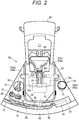
Fig. 2 is a plan view of a unit set area of the centrifugation transfer device. -
Fig. 3 is a perspective view of a tube winding bobbin around which a segment tube is wound and a segment pocket. -
Fig. 4 is an explanatory view illustrating a state where the tube winding bobbin is provided in a relay tube of the blood bag system. -
Fig. 5 is an explanatory view illustrating a state where the tube winding bobbin and the relay tube are attached according to another configuration example. -
Fig. 6A is a sectional view taken along the line VI-VI inFig. 3 .Fig. 6B is a sectional view illustrating a state where the tube winding bobbin is accommodated in the segment pocket. -
Fig. 7A is a perspective view of a tube winding bobbin according to a first modification.Fig. 7B is a perspective view of a tube winding bobbin according to a second modification. - Hereinafter, a preferred embodiment of the present invention will be described in detail with reference to the accompanying drawings.
- As illustrated in
Figs. 1 to 3 , atube winding bobbin 84 according to an embodiment of the present invention is set in acentrifugation transfer device 12 together with ablood bag system 10 by a user such as a medical worker. Thecentrifugation transfer device 12 centrifuges blood in theblood bag system 10 to generate and store a plurality of types of blood components. Hereinafter, a configuration including theblood bag system 10 and thecentrifugation transfer device 12 is referred to as a bloodproduct manufacturing system 14. - The
blood bag system 10 includes a preprocessor 15 (seeFig. 4 ) used for blood collection before centrifugation, and aseparation processor 16 that generates blood components by centrifugation and individually stores the blood components. Thepreprocessor 15 and theseparation processor 16 are connected by arelay tube 18. Therelay tube 18 connected to thepreprocessor 15 is cut before centrifugation, and theseparation processor 16 is in a state illustrated inFig. 1 , and is set in thecentrifugation transfer device 12. - The
preprocessor 15 of theblood bag system 10 collects whole blood from a donor and removes a predetermined blood component (for example, white blood cells) from the whole blood. Thus, thepreprocessor 15 includes a blood sampling needle, ablood sampling bag 15a (first bag: seeFig. 4 ), an initial flow blood bag, a filter (for example, a white blood cell removal filter), and the like, and is configured by connecting each member by a plurality of tubes. Theseparation processor 16 is connected to downstream of the filter via therelay tube 18. Specifically, thepreprocessor 15 stores initial blood of the whole blood of the donor collected through the blood sampling needle in the initial flow blood bag, and then stores residual blood in theblood sampling bag 15a. Furthermore, thepreprocessor 15 removes white blood cells in the filter by causing the whole blood stored in theblood sampling bag 15a to flow to the filter, and transfers the removed blood (white blood cell removed blood) to theseparation processor 16. - The
separation processor 16 of theblood bag system 10 includes a plurality of bags 20 (ablood bag 22, aPPP bag 24, and a medical solution bag 26), and is configured by connecting thebags 20 by a plurality oftubes 30. - The blood bag 22 (second bag) is directly connected to the
relay tube 18 connected to thepreprocessor 15 in a state of theblood bag system 10 provided as a product. Thus, theblood bag 22 stores the removed blood transferred from the filter during blood collection. Theblood bag 22 is set in thecentrifugation transfer device 12, and a centrifugal force is applied by operation of thecentrifugation transfer device 12. As a result, the removed blood in theblood bag 22 is centrifuged into blood components (platelet poor plasma (PPP) and red blood cells (RBC)) and the like having different specific gravities. Then, theblood bag 22 stores only the residual RBCs by transferring PPP during the operation of thecentrifugation transfer device 12 after centrifugation. - The PPP is supplied from the
blood bag 22, and thePPP bag 24 stores the PPP. The medical solution bag 26 stores in advance a red blood cell preservation solution such as MAP solution, SAGM solution, or OPTISOL. - Further, a
segment tube 28 is formed in theseparation processor 16 after the removed blood is transferred to theblood bag 22 and before theseparation processor 16 is set in thecentrifugation transfer device 12. Thesegment tube 28 includes a plurality of sealedtubes 28a having a predetermined length and having a closed lumen. Donor blood (removed blood) is present in the lumen of each sealedtube 28a. Therelay tube 18 connecting theblood bag 22 and the preprocessor 15 (filter) is cut near the filter and is further sealed at predetermined intervals, and thus the plurality of sealedtubes 28a is formed so as to be continuous in series. Thesegment tubes 28 are cut by the user as necessary and used for checking blood and the like. - The plurality of
tubes 30 of theseparation processor 16 is branched into a plurality of tubes via a branch connector 32 (Y-shaped connector). Specifically, the plurality oftubes 30 includes afirst tube 34 connecting theblood bag 22 and thebranch connector 32, asecond tube 36 connecting thePPP bag 24 and thebranch connector 32, and athird tube 38 connecting themedical solution bag 26 and thebranch connector 32. Thefirst tube 34 includes afirst flow path 34a, thesecond tube 36 includes asecond flow path 36a, and thethird tube 38 includes athird flow path 38a. The first tothird flow paths branch connector 32. - A breakable sealing member 40 (click tip) is provided at an end of the
first tube 34 closer to theblood bag 22. Similarly, abreakable sealing member 42 is provided at an end of thethird tube 38 closer to themedical solution bag 26. The sealingmembers first flow path 34a and thethird flow path 38a until breaking operation is performed, and prevent a liquid in theblood bag 22 and themedical solution bag 26 from being transferred to anotherbag 20. - The
centrifugation transfer device 12 in which theseparation processor 16 of theblood bag system 10 is set includes a box-shaped base body 44, alid 46 capable of opening and closing an upper surface of thebase body 44, and acentrifugal drum 48 provided in thebase body 44. Further, thebase body 44 of thecentrifugation transfer device 12 is provided with a motor (not illustrated) that rotates thecentrifugal drum 48, acontroller 50 that controls the operation of thecentrifugation transfer device 12, and anoperation display 52 for the user to confirm and operate. - The
centrifugal drum 48 has a plurality of (six) unit setareas 54 in which theseparation processor 16 can be set. A height of one unit setarea 54 is larger than a length of thebag 20 in a long-length direction, and is set in a range of 60° with respect to a rotation center of thecentrifugal drum 48. That is, the six unit setareas 54 are arranged side by side without a gap along a circumferential direction to constitute thecentrifugal drum 48 as an annular structure. - As illustrated in
Figs. 1 and2 , the unit setareas 54 apply a centrifugal force to theblood bag 22 as thecentrifugal drum 48 rotates. Specifically, each of the unit setareas 54 includes ablood bag pocket 56 accommodating theblood bag 22, aPPP bag pocket 58 accommodating thePPP bag 24, and a medicalsolution bag pocket 60 accommodating themedical solution bag 26 radially outside of thecentrifugal drum 48. - The
blood bag pocket 56 is provided at a circumferential center of the unit setarea 54 and has a larger volume than thePPP bag pocket 58 and the medicalsolution bag pocket 60. ThePPP bag pocket 58 and the medicalsolution bag pocket 60 are provided side by side in the circumferential direction radially outside of theblood bag pocket 56. - An
upper surface 54a of the unit setarea 54 is configured to arrange and hold the plurality oftubes 30 of theblood bag system 10. A part of thefirst tube 34 and a part of thesegment tube 28 are disposed in a central region 54a1 (first region) radially inside of theblood bag pocket 56 in theupper surface 54a. The central region 54a1 is provided with atop cover 62 that opens and closes an opening of theblood bag pocket 56. Further, a sensor 66 (optical sensor) that detects a part of thebreaker 64 breaking the sealingmember 40 and a state of blood flowing through thefirst tube 34 is provided at an arrangement position of thefirst tube 34 closed by thetop cover 62. - A part of the
first tube 34, a part of thebranch connector 32, a part of thesecond tube 36, and a part of thethird tube 38 that have passed through the central region 54a1 are disposed in a left region 54a2 (second region) of theupper surface 54a. The left region 54a2 is provided with aholder 68 that holds thebranch connector 32, aPPP clamp 70 that opens and closes thesecond flow path 36a of thesecond tube 36, and amedical solution clamp 72 that opens and closes thethird flow path 38a of thethird tube 38. - A part of the
segment tube 28 that passes through the central region 54a1 is disposed in a right region 54a3 (third region) of theupper surface 54a. The right region 54a3 is provided with asegment pocket 74 that accommodates the plurality of sealedtubes 28a of thesegment tube 28. - Furthermore, a
tube holder 76 that protruding upward of theupper surface 54a is provided radially outside of thePPP bag pocket 58 and the medicalsolution bag pocket 60 of the unit setarea 54. Thetube holder 76 has anouter wall 78 continuous with an outer peripheral edge of the unit setarea 54 and aninner wall 80 protruding inward of theouter wall 78 from the outer peripheral edge, and thesecond tube 36 is disposed between theouter wall 78 and theinner wall 80. Theinner wall 80 extends from near thePPP clamp 70 in the left region 54a2 (left side of the medical solution bag pocket 60) to a circumferential intermediate position of thePPP bag pocket 58, and guides thesecond tube 36 to thePPP bag pocket 58. - Further, the unit set
area 54 includes a slider 82 (pusher) that presses theblood bag 22 after centrifugation radially inside of theblood bag pocket 56. A surface of theslider 82 facing theblood bag 22 is formed as aninclined surface 82a. Theslider 82 moves forward and backward along a radial direction of thecentrifugal drum 48 under control of the controller 50 (seeFig. 1 ). - In the unit set
area 54, the user accommodates theblood bag 22 storing the removed blood in theblood bag pocket 56, theempty PPP bag 24 in thePPP bag pocket 58, and themedical solution bag 26 storing the medical solution in the medicalsolution bag pocket 60. Then, the unit setarea 54 centrifuges the removed blood in theblood bag 22 by the rotation of thecentrifugal drum 48, advances theslider 82 after the centrifugation, and presses theblood bag 22. As a result, PPP generated by centrifugation in theblood bag 22 is transferred to thePPP bag 24, and the RBC remains in theblood bag 22 after the transfer of PPP. Thereafter, theblood bag system 10 is taken out from thecentrifugation transfer device 12 by the user, and themedical solution bag 26 is hung on a stand (not illustrated). As a result, the red blood cell preservation solution is supplied from themedical solution bag 26 to theblood bag 22, and theblood bag 22 is storing RBC (blood product) including a medical solution. - Next, a configuration of the
tube winding bobbin 84 according to the present embodiment will be described with reference toFig. 3 . - The
tube winding bobbin 84 is a member provided for thesegment tube 28 of theblood bag system 10 to be wound around, and is accommodated in thesegment pocket 74 of the centrifugation transfer device 12 (unit set area 54) in a state where thesegment tube 28 is wound around. That is, thetube winding bobbin 84 is integrally accommodated with thesegment tube 28 in thesegment pocket 74, and this facilitates setting of thesegment tube 28 in thecentrifugation transfer device 12. - The
segment tube 28 has a plurality of (for example, seven to eight) sealedtubes 28a as described above. Acoupling seal part 28b that is sealed by crushing therelay tube 18 is formed between the adjacent sealedtubes 28a. An extending length of each of the sealedtubes 28a (the distance of an intermediate position between the adjacentcoupling seal parts 28b) is not limited, but is a dimension of, for example, about 6 cm to 8 cm. - Further, the
segment tube 28 includes anelongated coupling tube 28c that connects the plurality of sealedtubes 28a and theblood bag 22. In a state where theblood bag system 10 is set in thecentrifugation transfer device 12, thecoupling tube 28c extends on theupper surface 54a (the central region 54a1 and the right region 54a3) of the unit setarea 54 and allows the plurality of sealedtubes 28a to reach thesegment pocket 74. - The
tube winding bobbin 84 includes a windingpart 86 around which the plurality of sealedtubes 28a is wound, and a pair ofside parts 88 coupled to both ends of the windingpart 86 in an extending direction. The windingpart 86 and the pair ofside parts 88 are integrally molded to be continuous in series. - The winding
part 86 has a rectangular plate shape, and theside parts 88 are coupled to the windingpart 86 along a pair of long sides continuous to both ends in a short-length direction. The extending length along a long-length direction of the windingpart 86 is slightly shorter than the extending length of the plurality of sealedtubes 28a. For example, an extending length Lb (seeFig. 4 ) of the windingpart 86 in the long-length direction is set in a range of 5 cm to 7.5 cm. - A plate thickness of the winding
part 86 is to be set to an appropriate thickness corresponding to ends of the adjacent sealedtubes 28a and thecoupling seal parts 28b. For example, a thickness of the windingpart 86 is set to be in a range of about 5 mm to 20 mm. - Further, a plurality of
guide notches 90 that guides arrangement of thesegment tube 28 is provided on a pair of short sides (sides at both ends in the long-length direction) of the windingpart 86. The plurality ofguide notches 90 has a recessed shape (arc shape) in which the short sides are recessed inward, and a plurality of guide notches is arranged side by side along the short sides. A dimension along the short side of eachguide notch 90 is set to match an outer diameter of the sealedtube 28a. - The winding
part 86 formed as described above can be wound around the windingpart 86 while the plurality of sealedtubes 28a is folded at thecoupling seal part 28b. That is, a body of each sealedtube 28a extends on one plate surface of the windingpart 86, and both ends continuous with the body protrude from both ends of the windingpart 86 in the long-length direction. Thecoupling seal part 28b connected to both ends easily reverses an extending direction of thesegment tube 28 while being guided by anarbitrary guide notch 90, and the sealedtube 28a extends along the other plate surface of the windingpart 86. - Here, the
blood bag system 10 may be provided as a product as illustrated inFig. 4 , including thetube winding bobbin 84. Specifically, thetube winding bobbin 84 is provided on therelay tube 18 connecting theblood sampling bag 15a and theblood bag 22 storing blood, downstream of the filter (not illustrated) of thepreprocessor 15. For example, thetube winding bobbin 84 is provided together with theblood bag system 10 in a state where each of the pair ofside parts 88 has anattachment hole 88a and therelay tube 18 is inserted through the pair ofattachment hole 88a. - The pair of
attachment holes 88a is provided on one end of the pair ofside parts 88 in one long-length direction and on the other end of the pair ofside parts 88 in the other long-length direction. Eachattachment hole 88a has an inner diameter having a margin to some extent with respect to an outer diameter of therelay tube 18. That is, thetube winding bobbin 84 is displaceable along an extending direction of therelay tube 18. As described above, therelay tube 18 is cut before thecentrifugation transfer device 12 is set, and thus thetube winding bobbin 84 can be detached from a cut point of therelay tube 18. Therefore, in thetube winding bobbin 84, the plurality of sealedtubes 28a can be satisfactorily wound around the windingpart 86 when thesegment tube 28 is wound. - A method of providing the
tube winding bobbin 84 on therelay tube 18 is not limited, and for example, as illustrated inFig. 5 , oneattachment hole 86a may be provided on one side of the plate-shaped windingpart 86 in the long-length direction. Theattachment hole 86a is formed in a crest between twoadjacent guide notches 90 near oneside part 88. Therelay tube 18 is provided as a product together with theblood bag system 10 while being movably inserted into theattachment hole 86a. In therelay tube 18 passing through theattachment hole 86a of the windingpart 86, the plurality of sealedtubes 28a can be wound around the windingpart 86 with therelay tube 18 passing through theattachment hole 86a after the plurality of sealedtubes 28a is formed by a sealer (not illustrated). - Note that the
tube winding bobbin 84 may be fixed to therelay tube 18 when theblood bag system 10 is provided as a product. For example, thetube winding bobbin 84 is fixed to one end (for example, a vicinity of a cut point between thepreprocessor 15 and the separation processor 16) of the plurality of sealedtubes 28a to be formed, and thus the plurality of sealedtubes 28a can be wound with this fixed position as a base point. - In
Fig. 4 again, theblood bag system 10 is preferably provided with a plurality ofindicators 19 that guides formation of the sealedtube 28a in accordance with thetube winding bobbin 84. For example, eachindicator 19 is formed as a linear scale that goes around a surface of therelay tube 18 in a circumferential direction. - An interval Lt between the
adjacent indicators 19 of theindicators 19 is set to be slightly longer than the extending length Lb in the long-length direction of the windingpart 86 of thetube winding bobbin 84. Each of theindicators 19 guides a sealed position by the user when the sealedtube 28a is formed to indirectly lead the formation of each sealedtube 28a having a length corresponding to the windingpart 86. It is therefore preferable to set the interval Lt between theadjacent indicators 19 appropriately in consideration of a sealing range of therelay tube 18. - In
Fig. 3 again, the pair ofside parts 88 of thetube winding bobbin 84 is a plate body extending along the long side of the windingpart 86, and has a rectangular shape whose length in the long-length direction is longer than a length in the long-length direction of the windingpart 86. A short-length direction of the pair ofside parts 88 protrudes in a direction orthogonal to a surface direction of the windingpart 86. That is, thetube winding bobbin 84 has an H-shape in plan view. In thetube winding bobbin 84, the pair ofside parts 88 protrudes from both ends in the long-length direction and the plate thickness of the windingpart 86. This protrusion prevents thesegment tube 28 wound around the windingpart 86 from coming off. - The
tube winding bobbin 84 includes anengagement part 92 at one end of the pair ofside parts 88 in the long-length direction. Theengagement part 92 engages thetube winding bobbin 84 with awall 75 constituting thesegment pocket 74. In the present embodiment, theengagement part 92 includes a pair ofclaws 94 that can be caught by anedge 75a constituting anopening 74a of thesegment pocket 74. - The pair of
claws 94 extends outward in a width direction (direction orthogonal to a plate surface of the side part 88) from short sides of the pair ofside parts 88. The pair ofclaws 94 is coupled to an intermediate position of the short side of theside part 88, and is provided at positions opposite to each other across the windingpart 86. Extending ends of the pair ofclaws 94 protrude outward from theedge 74a of thesegment pocket 75. - A
barb 94a that is curved (or bent) with respect to an extending direction of the pair ofclaws 94 is formed at each extending end of the pair ofclaws 94. For example, thebarb 94a is curved toward the side of the pair of side parts 88 (a lower side inFig. 3 ) and is configured to be caught by theedge 75a of thesegment pocket 74, theedge 75a having a circular cross section. - On the other hand, the
segment pocket 74 of the centrifugation transfer device 12 (unit set area 54) has theopening 74a formed to be larger than a planar shape (H-shape) of thetube winding bobbin 84, and a region near theopening 74a formed as atapered space 74b that narrows with increase in depth in an insertion direction. Further, acylindrical space 74c extending with a constant inner diameter is formed in a deeper part than the region near theopening 74a (taperedspace 74b) of thesegment pocket 74. - As illustrated in
Fig. 6A , thewall 75 of thesegment pocket 74 constituting thecylindrical space 74c has a plurality of (four inFig. 6A ) guides 75b protruding inward. The plurality ofguides 75b guides the insertion of the pair ofside parts 88 of thetube winding bobbin 84. Therefore, the plurality ofguides 75b is constituted by a first set and a second set protruding in parallel from an inner surface (wall 75), and the first set and the second set face each other across thesegment pocket 74. - The plurality of
guides 75b includes a pair of ridges 75b1 protruding inward from the wall 75 (inner surface), and long sides of theside parts 88 are disposed between the pair of ridges 75b1. The pair of ridges 75b1 extends along an axial direction of thecylindrical space 74c and guides the insertion of theside parts 88. - The
tube winding bobbin 84 and theblood bag system 10 according to the present embodiment are basically configured as described above, and the operation thereof will be described below. - As described above, the
blood bag system 10 stores, in theblood bag 22, the removed blood obtained by removing a predetermined component (white blood cells) from the whole blood of the donor with use of thepreprocessor 15 during blood collection by the user (medical worker). In astorage space 22a, an appropriate volume of blood in accordance with the donor is stored. - Thereafter, the user separates the
separation processor 16 of theblood bag system 10 from thepreprocessor 15 in order to centrifuge the removed blood. At this time, thecut relay tube 18 is sealed at a plurality of points at predetermined intervals by a sealer (not illustrated) to form thesegment tube 28 having the plurality of sealedtubes 28a. As illustrated inFig. 4 , in theblood bag system 10, the plurality ofindicators 19 is indicated on therelay tube 18, and thus the user can be guided to seal points of theindicators 19. After thesegment tube 28 is formed, the user sets theseparation processor 16 in thecentrifugation transfer device 12. - As illustrated in
Fig. 2 , theblood bag 22 is accommodated in theblood bag pocket 56, and the tube 30 (thebranch connector 32 and the first tothird tubes upper surface 54a. Further, thePPP bag 24 is accommodated in thePPP bag pocket 58, and themedical solution bag 26 is accommodated in the medicalsolution bag pocket 60. - In the
segment tube 28, thecoupling tube 28c extends from the central region 54a1 of theupper surface 54a toward the right region 54a3, and thecoupling tube 28c further extends outward in a centrifugal direction in the right region 54a3. Thesegment pocket 74 is attached to the right region 74a3 with theopening 54a slightly inclined inward in the centrifugal direction to facilitate insertion of thesegment tube 28. - In the
segment tube 28, the plurality of sealedtubes 28a is wound around thetube winding bobbin 84 by the user. The plurality of sealedtubes 28a arranged side by side in the extending direction is wound around thetube winding bobbin 84 while extending along one surface and the other surface, alternately, of the windingpart 86. As a result, the plurality of sealedtubes 28a is easily disposed inside of the long sides of the pair ofside parts 88. - The
tube winding bobbin 84 is accommodated in thesegment pocket 74 together with the wound sealedtube 28a. At this time, as illustrated inFig. 6B , the user can insert the long sides of the pair ofside parts 88 into the plurality ofguides 75b (parts between the pair of ridges 75b1) provided on thewall 75 constituting thesegment pocket 74 in a state where a position of thetube winding bobbin 84 is defined. - The
tube winding bobbin 84 maintains a winding state of the plurality of sealedtubes 28a even when accommodated in thesegment pocket 74. That is, even if the sealedtube 28a moves so as to spread (separate from the winding part 86) in thesegment pocket 74, the sealedtube 28a cannot be detached from a narrow space between the windingpart 86 and thewall 75. Therefore, thetube winding bobbin 84 can prevent the plurality of sealedtubes 28a from coming off from thesegment pocket 74. - Further, in the
tube winding bobbin 84, the pair ofclaws 94 constituting theengagement part 92 is caught by theedge 75a as thesegment pocket 74 is inserted. This also suppresses detachment of thetube winding bobbin 84 from thewall 75. - After the blood bag system 10 (segment tube 28) is set, the
centrifugation transfer device 12 centrifuges the removed blood in theblood bag 22 into blood components (PPP, RBC, and the like) having different specific gravities by rotating thecentrifugal drum 48 under the control of thecontroller 50. As described above, thesegment tube 28 continues to be well accommodated in thesegment pocket 74, and does not interfere with a periphery during centrifugation. The blood in the plurality of sealedtubes 28a extending along the centrifugal direction is separated into blood components by centrifugation. - After centrifugation, the
centrifugation transfer device 12 presses theblood bag 22 with theslider 82. As a result, PPP having a light specific gravity flows out from theblood bag 22, and the PPP flows through thefirst tube 34, thebranch connector 32, and thesecond tube 36 in that order and flows into thePPP bag 24. Further, when the PPP is transferred from theblood bag 22 to thePPP bag 24, thecentrifugation transfer device 12 retracts theslider 82 such that theblood bag 22 can be taken out from theblood bag pocket 56. - Thereafter, the user removes the
blood bag system 10 from thecentrifugation transfer device 12. At this time, the engagement of theengagement part 92 of thetube winding bobbin 84 is released, and thesegment tube 28 is also taken out together with thetube winding bobbin 84. Upon release of winding of the sealedtube 28a, thetube winding bobbin 84 is reused for the next centrifugation. Further, the user suspends themedical solution bag 26 on the stand to supply the red blood cell preservation solution to theblood bag 22. As a result, the RBC including the red blood cell preservation solution is stored in theblood bag 22. - Note that the present invention is not limited to the above embodiment, and various modifications can be made in accordance with the gist of the invention. For example, in the above embodiment, the
guide 75b is provided inside thesegment pocket 74, but theguide 75b does not have to be provided. Further, instead of guiding the pair ofside parts 88 of thetube winding bobbin 84, theguide 75b can engage with the pair ofside parts 88. Alternatively, thetube winding bobbin 84 may include the windingpart 86 having a substantially tubular shape. - Hereinafter, some other modifications of the present invention will be described. Note that, in the following description, the same reference signs are given to constituent elements having the same configurations or the same functions as constituent elements of the above embodiment, and a detailed description thereof will be omitted.
- In a
tube winding bobbin 84A according to a first modification illustrated inFig. 7A , the lengths in the long-length direction of the windingpart 86 and the pair ofside parts 88 are set to the same dimension, and thetube winding bobbin 84A has an H-shape in plan view. Thetube winding bobbin 84A is configured such that the pair of long sides (hereinafter, referred to as protruding sides 96) of eachside part 88 is fittable to thewall 75 of thesegment pocket 74. That is, the protrudingsides 96 cooperate with thewall 75 to serve as anengagement part 92A that prevents detachment of thetube winding bobbin 84A. - The
tube winding bobbin 84A configured as described above can also obtain similar effects to effects of the above embodiment. The manufacturing can be facilitated and the manufacturing cost can be reduced particularly by simplified configurations of thetube winding bobbin 84A and the centrifugation transfer device 12 (segment pocket 74) . - In a
tube winding bobbin 84B according to a second modification illustrated inFig. 7B , a pair ofside parts 98 coupled to the windingpart 86 has an arc shape in plan view. A curvature of the pair ofside parts 98 is set to be the same as a curvature of an inner surface of thesegment pocket 74, and a diameter of a virtual circle formed by the pair ofside parts 98 matches an inner diameter of thesegment pocket 74. - That is, the
tube winding bobbin 84B has a configuration in which an outer surface of the pair ofside parts 98 is in surface contact with and fitted to thewall 75 of thesegment pocket 74, and the pair ofside parts 98 functions as anengagement part 92B that prevents detachment of thetube winding bobbin 84B. Thetube winding bobbin 84B configured as described above can also obtain similar effects to effects of the above embodiment. In particular, in the pair ofside parts 98, the sealedtube 28a wound around the windingpart 86 can be disposed on an inner surface of the arc shape. This can suppress disengagement of the sealedtube 28a before insertion into thesegment pocket 74 or the like. - The
engagement parts tube winding bobbins segment pocket 74. - Technical ideas and effects that can be recognized from the above embodiment will be described below.
- In the
tube winding bobbin 84, the plurality of sealedtubes 28a can be accommodated in the pocket (segment pocket 74) of thecentrifugation transfer device 12 in a state of being wound around the windingpart 86 of thetube winding bobbin 84. Thus, the plurality of sealedtubes 28a is folded back without being disordered, and the plurality of sealedtubes 28a can be smoothly inserted into thesegment pocket 74. - Further, the winding
part 86 is as long as the extending length of the sealedtube 28a or shorter than the extending length of the sealedtube 28a. Thus, in thetube winding bobbin 84, the sealedtube 28a can be extended along one plate surface of the windingpart 86 and folded back at a boundary between the sealedtubes 28a, and the plurality of sealedtubes 28a can be disposed stably. - Further, the winding
part 86 has a plate shape or a substantially tubular shape. As a result, for example, the windingpart 86 can arrange the plurality of sealedtubes 28a to be easily folded back. In a state of being accommodated in thesegment pocket 74, the plurality of sealedtubes 28a can satisfactorily receive a centrifugal force along the extending direction of the plurality of sealedtubes 28a. - Further, the winding
part 86 includes theguide notch 90 that guides arrangement of the plurality of sealedtubes 28a or thecoupling seal part 28b connecting the plurality of sealedtubes 28a to each other. Thus, in thetube winding bobbin 84, the plurality of sealedtubes 28a can be neatly wound around the windingpart 86, and thetube winding bobbin 84 can be more smoothly inserted into thesegment pocket 74 together with the plurality of sealedtubes 28a. - Further, the
engagement parts wall 75 constituting the pocket (segment pocket 74) are provided. As a result, thetube winding bobbin 84 is prevented from being detached from thesegment pocket 74 in a state of being accommodated in thesegment pocket 74. - Further, the
engagement part 92 includes theclaws 94 that can be caught by theedge 75a constituting theopening 74a of the pocket (segment pocket 74). Thus, in thetube winding bobbin 84, theclaw 94 can easily engage with theedge 74a of thesegment pocket 75. Theclaw 94 engaged with theedge 75a enables thetube winding bobbin 84 to be easily taken out (disengaged) from thesegment pocket 74. - Further, the
engagement parts 92A may include the protrudingsides 96 of the pair ofside parts 88 that is fittable to thewall 75 constituting the pocket (segment pocket 74). As a result, thetube winding bobbin 84A is engaged with thesegment pocket 74 only by the operation of inserting thetube winding bobbin 84 into thesegment pocket 74. Further, thetube winding bobbin 84 itself has a simple configuration, and thus allows the plurality of sealedtubes 28a to be smoothly wound. - Further, the
engagement part 92B includes the outer surface of the pair ofside parts 98 that can be in surface contact with thewall 75 constituting the pocket (segment pocket 74). Thus, thetube winding bobbin 84B is firmly engaged with thesegment pocket 74 only by the operation of being inserted into thesegment pocket 74. - Further, the
blood bag system 10 includes the first bag (blood sampling bag 15a) configured to accommodate blood, the second bag (blood bag 22) configured to accommodate a predetermined component in the blood, and the tube (relay tube 18) connecting the first bag and the second bag, in which the tube is provided with thetube winding bobbin 84 around which the tube can be wound, and thetube winding bobbin 84 includes the winding part around 86 which the tube is wound, and a pair ofside parts 88 coupled to both ends of the windingpart 86 and protruding in a thickness direction of the windingpart 86. Thus, theblood bag system 10 can be provided together with thetube winding bobbin 84. By using thetube winding bobbin 84, the plurality of sealedtubes 28a can be easily accommodated, work efficiency can be improved, and the plurality of sealedtubes 28a can be prevented from sticking out. - The
indicators 19 are provided on the surface of the tube (relay tube 18) at predetermined intervals, and the length of the windingpart 86 is set to be equal to or less than a tube length between theadjacent indicators 19. Thus, the plurality of sealedtubes 28a can be easily formed along theindicators 19, and can be easily wound around thetube winding bobbin 84. - The
tube winding bobbin 84 has at least oneattachment hole tube winding bobbin 84 to move along the extending direction of the tube. As a result, theblood bag system 10 allows thetube winding bobbin 84 to be detached from therelay tube 18 at time of use and allows the plurality of sealedtubes 28a to be satisfactorily wound around thetube winding bobbin 84.
Claims (11)
- A tube winding bobbin attachable to a centrifugation transfer device in which a blood bag system is set, whereinthe blood bag system includes a tube member including a plurality of sealed tubes, the plurality of sealed tubes extending for a predetermined length and having a closed lumen therein,the tube winding bobbin includesa winding part around which the tube member is wound, anda pair of side parts coupled to both ends of the winding part and protruding in a thickness direction of the winding part, andthe winding part has a length that is set such that the tube member is wound around the winding part in a state where the tube member is folded at a point of a coupling seal part that connects the plurality of sealed tubes to each other.
- The tube winding bobbin according to claim 1, wherein
the winding part has a length that is same as an extension length of the plurality of sealed tubes or shorter than the extending length of the plurality of sealed tubes. - The tube winding bobbin according to claim 1 or 2, wherein
the winding part has a plate shape or a substantially tubular shape. - The tube winding bobbin according to any one of claims 1 to 3,
wherein the winding part includes the coupling seal part that connects the plurality of sealed tubes to each other or a guide notch that guides arrangement of the plurality of sealed tubes or. - The tube winding bobbin according to any one of claims 1 to 4, comprising
an engagement part that is engageable with a wall constituting a pocket of the centrifugation transfer device. - The tube winding bobbin according to claim 5, wherein
the engagement part includes a claw that can be caught by an edge constituting an opening of the pocket. - The tube winding bobbin according to claim 5 or 6, wherein
the engagement part includes protruding sides of the pair of side parts, the protruding sides being fittable to the wall constituting the pocket. - The tube winding bobbin according to any one of claims 5 to 7, wherein
the engagement part includes an outer surface of the pair of side parts configured to be in surface contact with the wall constituting the pocket. - A blood bag system comprising:a first bag configured to accommodate blood;a second bag configured to accommodate a predetermined component in the blood; anda tube connecting the first bag and the second bag, whereinthe tube is provided with a tube winding bobbin around which the tube can be wound, andthe tube winding bobbin includesa winding part around which the tube is wound, anda pair of side parts coupled to both ends of the winding part and protruding in a thickness direction of the winding part.
- The blood bag system according to claim 9, whereinthe tube is provided with indicators on a surface of the tube at predetermined intervals, andthe winding part has a length that is set to be equal to or less than a tube length between indicators adjacent each other.
- The blood bag system according to claim 9 or 10, wherein the tube winding bobbin includes at least one attachment hole into which the tube is inserted and that allows the tube winding bobbin to move along an extending direction of the tube.
Applications Claiming Priority (2)
| Application Number | Priority Date | Filing Date | Title |
|---|---|---|---|
| JP2019047250 | 2019-03-14 | ||
| PCT/JP2020/004791 WO2020184017A1 (en) | 2019-03-14 | 2020-02-07 | Tube winding bobbin and blood bag system |
Publications (2)
| Publication Number | Publication Date |
|---|---|
| EP3932443A1 true EP3932443A1 (en) | 2022-01-05 |
| EP3932443A4 EP3932443A4 (en) | 2022-11-16 |
Family
ID=72426390
Family Applications (1)
| Application Number | Title | Priority Date | Filing Date |
|---|---|---|---|
| EP20770432.1A Withdrawn EP3932443A4 (en) | 2019-03-14 | 2020-02-07 | Tube winding bobbin and blood bag system |
Country Status (5)
| Country | Link |
|---|---|
| US (1) | US20220143281A1 (en) |
| EP (1) | EP3932443A4 (en) |
| JP (1) | JP6848124B2 (en) |
| CN (1) | CN113453734A (en) |
| WO (1) | WO2020184017A1 (en) |
Families Citing this family (1)
| Publication number | Priority date | Publication date | Assignee | Title |
|---|---|---|---|---|
| CN117771462B (en) * | 2024-02-26 | 2024-05-10 | 四川大学华西医院 | Bone marrow extraction equipment |
Family Cites Families (18)
| Publication number | Priority date | Publication date | Assignee | Title |
|---|---|---|---|---|
| JPS4317903Y1 (en) * | 1965-07-16 | 1968-07-24 | ||
| JPS53120786U (en) * | 1977-03-03 | 1978-09-26 | ||
| JPS5636840Y2 (en) * | 1978-04-07 | 1981-08-29 | ||
| JPS6159308U (en) * | 1984-09-12 | 1986-04-21 | ||
| JPH0226508Y2 (en) * | 1985-05-25 | 1990-07-19 | ||
| JPH04112586A (en) * | 1990-09-03 | 1992-04-14 | Tokin Corp | Permanent current switch and manufacture thereof |
| JPH05226165A (en) * | 1992-02-12 | 1993-09-03 | Tokyo Electric Co Ltd | Trance |
| US5265822A (en) * | 1992-07-13 | 1993-11-30 | Shober Jr Robert C | IV tube support assembly |
| CA2134311C (en) * | 1993-10-26 | 2004-09-07 | Kenneth L. Carr | Cartridge for in-line microwave warming apparatus |
| JPH0947688A (en) * | 1995-08-07 | 1997-02-18 | Nissho Corp | Method and apparatus for centrifuging blood |
| JPH1190990A (en) * | 1997-09-17 | 1999-04-06 | Mitsubishi Cable Ind Ltd | Heat treating method for tube |
| US7276046B1 (en) * | 2002-11-18 | 2007-10-02 | Biosynergy, Inc. | Liquid conductive cooling/heating device and method of use |
| JP2012070905A (en) * | 2010-09-28 | 2012-04-12 | Terumo Corp | Wire material holder and medical wire material set with the same |
| US10335802B2 (en) * | 2015-03-18 | 2019-07-02 | Terumo Kabushiki Kaisha | Centrifuge and segment holder |
| JP6456734B2 (en) * | 2015-03-18 | 2019-01-23 | テルモ株式会社 | Hanging jig and additive liquid transfer method |
| JP6779676B2 (en) * | 2016-06-27 | 2020-11-04 | テルモ株式会社 | Blood bag system processing method and workstation |
| CN107320794A (en) * | 2017-08-16 | 2017-11-07 | 周旭 | Thoracic cavity closed drainage system |
| CN208279113U (en) * | 2018-05-07 | 2018-12-25 | 郑州大学第一附属医院 | Medical basin line device |
-
2020
- 2020-02-07 US US17/435,381 patent/US20220143281A1/en not_active Abandoned
- 2020-02-07 WO PCT/JP2020/004791 patent/WO2020184017A1/en not_active Ceased
- 2020-02-07 CN CN202080014467.5A patent/CN113453734A/en active Pending
- 2020-02-07 EP EP20770432.1A patent/EP3932443A4/en not_active Withdrawn
- 2020-02-07 JP JP2020509561A patent/JP6848124B2/en active Active
Also Published As
| Publication number | Publication date |
|---|---|
| US20220143281A1 (en) | 2022-05-12 |
| WO2020184017A1 (en) | 2020-09-17 |
| JP6848124B2 (en) | 2021-03-24 |
| JPWO2020184017A1 (en) | 2021-03-18 |
| CN113453734A (en) | 2021-09-28 |
| EP3932443A4 (en) | 2022-11-16 |
Similar Documents
| Publication | Publication Date | Title |
|---|---|---|
| EP2349395B1 (en) | Blood bag system and cassette | |
| EP2500048A1 (en) | Blood bag system and blood treatment method | |
| CN102971021B (en) | Clip and blood bag system | |
| JP2012510298A (en) | Blood bag system and cassette | |
| US9820912B2 (en) | Blood bag system | |
| US20220143280A1 (en) | Blood bag system with retaining cassette | |
| US20220143281A1 (en) | Blood bag system with tube winding bobbin | |
| US10335802B2 (en) | Centrifuge and segment holder | |
| EP3939632A1 (en) | Blood bag system | |
| JP6848108B1 (en) | Medical bag system and centrifuge system | |
| EP3939631A1 (en) | Blood bag system | |
| CN115485011A (en) | Blood bag system, centrifugal separation system, and clamp | |
| EP3943059A1 (en) | Blood bag system | |
| EP3922298B1 (en) | Blood bag system and clamp | |
| EP3932469A1 (en) | Blood bag system and clamp |
Legal Events
| Date | Code | Title | Description |
|---|---|---|---|
| STAA | Information on the status of an ep patent application or granted ep patent |
Free format text: STATUS: THE INTERNATIONAL PUBLICATION HAS BEEN MADE |
|
| PUAI | Public reference made under article 153(3) epc to a published international application that has entered the european phase |
Free format text: ORIGINAL CODE: 0009012 |
|
| STAA | Information on the status of an ep patent application or granted ep patent |
Free format text: STATUS: REQUEST FOR EXAMINATION WAS MADE |
|
| 17P | Request for examination filed |
Effective date: 20211001 |
|
| AK | Designated contracting states |
Kind code of ref document: A1 Designated state(s): AL AT BE BG CH CY CZ DE DK EE ES FI FR GB GR HR HU IE IS IT LI LT LU LV MC MK MT NL NO PL PT RO RS SE SI SK SM TR |
|
| DAV | Request for validation of the european patent (deleted) | ||
| DAX | Request for extension of the european patent (deleted) | ||
| A4 | Supplementary search report drawn up and despatched |
Effective date: 20221019 |
|
| RIC1 | Information provided on ipc code assigned before grant |
Ipc: A61M 1/02 20060101AFI20221013BHEP |
|
| STAA | Information on the status of an ep patent application or granted ep patent |
Free format text: STATUS: THE APPLICATION HAS BEEN WITHDRAWN |
|
| 18W | Application withdrawn |
Effective date: 20230502 |