EP3932266B1 - Low-temperature cooking machine - Google Patents
Low-temperature cooking machine Download PDFInfo
- Publication number
- EP3932266B1 EP3932266B1 EP19922879.2A EP19922879A EP3932266B1 EP 3932266 B1 EP3932266 B1 EP 3932266B1 EP 19922879 A EP19922879 A EP 19922879A EP 3932266 B1 EP3932266 B1 EP 3932266B1
- Authority
- EP
- European Patent Office
- Prior art keywords
- heating unit
- food
- flexible
- cavity
- flexible heating
- Prior art date
- Legal status (The legal status is an assumption and is not a legal conclusion. Google has not performed a legal analysis and makes no representation as to the accuracy of the status listed.)
- Active
Links
Images


Classifications
-
- A—HUMAN NECESSITIES
- A47—FURNITURE; DOMESTIC ARTICLES OR APPLIANCES; COFFEE MILLS; SPICE MILLS; SUCTION CLEANERS IN GENERAL
- A47J—KITCHEN EQUIPMENT; COFFEE MILLS; SPICE MILLS; APPARATUS FOR MAKING BEVERAGES
- A47J27/00—Cooking-vessels
-
- A—HUMAN NECESSITIES
- A47—FURNITURE; DOMESTIC ARTICLES OR APPLIANCES; COFFEE MILLS; SPICE MILLS; SUCTION CLEANERS IN GENERAL
- A47J—KITCHEN EQUIPMENT; COFFEE MILLS; SPICE MILLS; APPARATUS FOR MAKING BEVERAGES
- A47J27/00—Cooking-vessels
- A47J27/10—Cooking-vessels with water-bath arrangements for domestic use
-
- A—HUMAN NECESSITIES
- A47—FURNITURE; DOMESTIC ARTICLES OR APPLIANCES; COFFEE MILLS; SPICE MILLS; SUCTION CLEANERS IN GENERAL
- A47J—KITCHEN EQUIPMENT; COFFEE MILLS; SPICE MILLS; APPARATUS FOR MAKING BEVERAGES
- A47J27/00—Cooking-vessels
- A47J27/14—Cooking-vessels for use in hotels, restaurants, or canteens
- A47J27/18—Cooking-vessels for use in hotels, restaurants, or canteens heated by water-bath, e.g. pasta-cookers
-
- A—HUMAN NECESSITIES
- A47—FURNITURE; DOMESTIC ARTICLES OR APPLIANCES; COFFEE MILLS; SPICE MILLS; SUCTION CLEANERS IN GENERAL
- A47J—KITCHEN EQUIPMENT; COFFEE MILLS; SPICE MILLS; APPARATUS FOR MAKING BEVERAGES
- A47J36/00—Parts, details or accessories of cooking-vessels
-
- A—HUMAN NECESSITIES
- A47—FURNITURE; DOMESTIC ARTICLES OR APPLIANCES; COFFEE MILLS; SPICE MILLS; SUCTION CLEANERS IN GENERAL
- A47J—KITCHEN EQUIPMENT; COFFEE MILLS; SPICE MILLS; APPARATUS FOR MAKING BEVERAGES
- A47J36/00—Parts, details or accessories of cooking-vessels
- A47J36/24—Warming devices
- A47J36/2494—Warming devices using heat storage elements or materials, e.g. lava stones
-
- A—HUMAN NECESSITIES
- A47—FURNITURE; DOMESTIC ARTICLES OR APPLIANCES; COFFEE MILLS; SPICE MILLS; SUCTION CLEANERS IN GENERAL
- A47J—KITCHEN EQUIPMENT; COFFEE MILLS; SPICE MILLS; APPARATUS FOR MAKING BEVERAGES
- A47J36/00—Parts, details or accessories of cooking-vessels
- A47J36/32—Time-controlled igniting mechanisms or alarm devices
Definitions
- the present invention relates to the field of electric cooking apparatuses, in particular to a low-temperature cooking machine according to the preamble of claim 1.
- the existing low-temperature cooking machines usually employ two products or have two separate products at the same time: a thermostat water bath (the temperature is usually set between 20°C and 99°C) and a vacuum plastic package machine.
- the vacuum low-temperature cooking method is to pack the food densely by vacuum pumping or using a preservative film first, and then put the food into a stirring thermostat water bath and cook the food at about 65°C low temperature; in addition, the cooking temperature and duration may be different for different foods.
- the method can preserve the original taste of the food, the fragrance of the spices and the primary color of the food to the greatest extent; besides, the cooking method is healthier, and is favored by more and more consumers.
- a low-temperature cooking machine is known from EP 2 816 939 B.
- the apparatus comprises a dual-chamber container that includes an inner bag enclosed within an outer bag.
- the inner bag may include a zip lock for sealing the bag.
- a fluid inlet port is in fluid communication with a chamber inside the outer bag but not with the chamber inside the inner bag.
- a fluid outlet port is also in fluid communication with the chamber inside the outer bag and not with the chamber inside the inner bag.
- a vacuum port penetrates the outer bag and is in fluid communication with the inner bag. The vacuum port is not in fluid communication with the space surrounding the inner bag within the outer bag.
- the inner bag can be opened to access the chamber inside the inner bag, for example to place or retrieve a food item.
- a heating element electrically connected to an electrical connector may optionally be included in the dual camber food container.
- the temperature of the liquid circulating through the outer bag is controlled by control unit.
- the heat transfer liquid may include water.
- a container with a pocket for holding a removable food container is provided.
- the exterior container may optionally be fabricated from a flexible heat insulating material as for example silicone rubber.
- the exterior container optionally includes a liquid outflow port and a fluid inlet port for establishing fluid communication with a space for holding heat transfer liquid between the pocket and the exterior walls of the container.
- the pocket may optionally be fabricated from a flexible material that conforms to the outside surfaces of the food container under the influence of pressure exerted by the heat transfer liquid.
- WO 2017/197482 A1 relates to a cooking appliance and method for controlling pressure, temperature and flavoring of food items during a cooking process.
- the sous-vide appliance includes a lid and a base member.
- a food item is placed in a plastic bag and set on resilient heating pad.
- a deformable membrane of the lid is inflated, flattening the plastic bag and the food item, and evacuating the air from inside the bag.
- the heat-sealing bar is activated to seal the bag at its opening in an airless, vacuum-like condition.
- the bag is then sealed by heat-sealing bars.
- the flexible membrane comes into contact with the heating pad of the base member, when the lid is closed over the base member.
- the lid is movably retained to the base member by a hinge.
- the lid contains a mini air compressor and an electronically-controlled precision mini air pressure regulator for controlling the degree of inflation of the membrane and the pressure to be applied to the food item being cooked.
- the inflatable membrane is made of concentric ridges extending from the outside surface of the flexible skin-like material.
- the flexible membrane is made of a washable, heat-resistant, food-grade silicon or latex material for example. It is also said the base member may have a similar inflatable bladder mounted therein facing the membrane.
- the object of the present invention is to provide a low-temperature cooking machine that can be operated more simply and has a higher level of product integration.
- the present invention provides a low-temperature cooking machine according to claim 1.
- the low-temperature cooking machine comprises a food cooking cavity for receiving the food, and the flexible heating unit at least partially surrounds the food cooking cavity.
- the flexible heating unit is a liquid heating bag connected with a water heater.
- the low-temperature cooking machine comprises an upper cover pivotally mounted on the base, the upper flexible heating unit is arranged in an upper cover cavity of the upper cover, and the upper cover cavity is divided by the upper flexible heating unit into an upper medium storage area and an upper food cooking cavity; the base cavity is divided by the lower flexible heating unit into a lower food cooking cavity and a lower medium storage area; wherein the lower food cooking cavity, the lower flexible heating unit and the lower medium storage area are sequentially arranged in a separate manner from top to bottom in the base cavity; the upper medium storage area, the upper flexible heating unit and the upper food cooking cavity are sequentially arranged in a separate manner from top to bottom in the upper cover cavity.
- the low-temperature cooking machine comprises a base and an upper cover pivotally mounted on the base, wherein the flexible heating unit is arranged in a base cavity of the base, and the food cooking cavity is formed in the base cavity; wherein the food can be put into the food cooking cavity when the upper cover is pivotally opened, and the upper cover encloses the food cooking cavity when the upper cover is pivotally closed.
- the flexible heating unit is arranged on the inner side of the upper cover.
- the low-temperature cooking machine comprises a flexible medium storage unit connected with a medium pipe, wherein the pump is a pressure booster pump for pumping a pressurized medium toward the flexible medium storage unit through the medium pipe, and the flexible heating unit is pushed by the boosted pressure of the flexible medium storage unit to closely contact with and heat the food.
- the low-temperature cooking machine comprises a base, wherein the flexible heating unit, the flexible medium storage unit and the food cooking cavity for receiving the food are arranged in a base cavity of the base, the flexible heating unit at least partially surrounds the food cooking cavity, and the flexible medium storage unit is able to at least partially contact with the flexible heating unit.
- the flexible medium storage unit is a medium storage bag.
- the base cavity is divided by the flexible heating unit into the food cooking cavity and a medium storage area serving as the flexible medium storage unit.
- the low-temperature cooking machine comprises an upper cover pivotally mounted on the base, wherein the medium storage area, the flexible heating unit and the food cooking cavity are transversely and sequentially arranged in a separate manner in the base cavity, and the upper cover covers the base to enclose the medium storage area.
- the medium pipe is an air intake passage
- the pump is an air pump that blows air to the flexible medium storage unit through the air intake passage.
- the low-temperature cooking machine comprises an air pump controller for monitoring the air content in the food cooking cavity.
- the low-temperature cooking machine comprises a heating controller for monitoring the heating temperature of the flexible heating unit.
- the flexible heating unit comprises a thermostatically controlled heating unit.
- the cooking temperature of the low-temperature cooking machine is 60 ⁇ 80°C.
- the low-temperature cooking machine in the present invention is a novel cooking apparatus, in which, under the action of the pump, the flexible heating unit that serves as a heater can be deformed and directly contact with the food, thereby directly heats and cook the food; under the joint action of the pump and the flexible heating unit, the food can be placed in a vacuum food cooking cavity and heated directly by the flexible heating unit.
- the low-temperature cooking machine in the present invention is a novel integrated apparatus and can replace an existing low-temperature cooking apparatus having a thermostat water bath and a vacuum plastic package machine.
- the present invention provides a novel low-temperature cooking machine, as shown in Figs. 1a-1b .
- a similar low-temperature cooking machine not belonging to the present invention is shown in Fig. 2a-2b .
- the low-temperature cooking machine comprises a flexible heating unit 1 (usually including a liquid heating bag 11 and a water heater 12, or see figure 6 ) and a pump 2 for providing pressure or suction to cause the flexible heating unit 1 to deform and contact with and heat food 41.
- the low-temperature cooking machine in the present invention is a novel cooking apparatus, in which, under the action of the pump 2, the flexible heating unit 1 that serves as a heater can be deformed and directly contact with food 41, so as to directly heat and cook the food 41.
- the low-temperature cooking machine comprises a food cooking cavity 4 for receiving the food 41, wherein the flexible heating unit 1 at least partially surrounds the food cooking cavity 4; wherein the food cooking cavity 4 is a closed chamber, the pump 2 is an air pump for vacuuming the food cooking cavity 4, and the flexible heating unit 1 is in close contact with and heats the food 41 under vacuum suction.
- this technical scheme mainly employs air suction from the food cooking cavity 4; specifically, the user may directly put the food 41 into the food cooking cavity 4, and the pump 2 pumps air out of the food cooking cavity 4, so that the flexible heating unit 1 is deformed under the suction and thereby closely contact with the food 41, thus the food 41 is in a vacuum-tight cooking environment and the flexible heating unit 1 that serves as a heater heats and cooks the food 41.
- a vacuumed cooking state can be established between the food 41 and the flexible heating unit 1 that serves as a heater, so as to replace a vacuum plastic package machine and avoid the use of a vacuum preservative bag.
- the flexible heating unit 1 may be a heating unit that requires replacing and replenishing a flexible heating material in time or may be a reusable heating unit.
- the flexible heating unit 1 is a reusable heating unit, both the operation step of adding water (for water bath) in time and the operation step of bagging and vacuuming in the existing low-temperature cooking machines can be omitted, thus the operation steps of cooking can be simplified.
- the low-temperature cooking machine in the present invention is a novel apparatus and can replace the existing low-temperature cooking apparatus having a thermostat water bath and a vacuum plastic package machine.
- the flexible heating unit 1 may partially contact with the food 41 or surround the food 41, so as to heat the food.
- the flexible heating unit 1 is arranged around the food cooking cavity 4 (see Fig. 2a-2b ), or the flexible heating unit 1 is at least arranged at two sides of the food 41 (see Fig. 1a-1b ), or the flexible heating unit 1 may be arranged at one side of the food 41.
- the flexible heating unit 1 is a liquid heating bag 11 connected with a water heater 12, the liquid heating bag 11 may be a flexible bag filled with water, and the water heater 12 is connected with the flexible bag or arranged in the flexible bag.
- the flexible heating unit 1 may be made of a flexible material connected to other heating devices; for example, the flexible heating unit 1 may include a deformable flexible material such as silicone.
- the low-temperature cooking machine comprises a base 5 and an upper cover 6 pivotally mounted on the base 5, wherein the flexible heating unit 1 is arranged in a base cavity of the base 5, and the food cooking cavity 4 is formed in the base cavity; wherein the food 41 may be put into the food cooking cavity 4 when the upper cover 6 is pivotally opened, and the upper cover 6 encloses the food cooking cavity 4 when the upper cover 6 is pivotally closed. That is to say, when the upper cover 6 is pivotally opened around a pivot shaft (see the pivot shaft 10 in Figs.
- the closed food cooking cavity 4 is opened at the same time, thereby the food 41 can be placed into the food cooking cavity 4; after the upper cover 6 is pivotally closed on the base 5, the food cooking cavity 4 becomes an enclosed chamber, so that the food 41 in the food cooking cavity 4 can be vacuum-pumped with the pump 2 that serves as a suction pump.
- the flexible heating unit 1 may also be arranged on the inner side of the upper cover 6, the food cooking cavity 4 may be arranged in the base cavity or in the upper cover cavity, or may be arranged in the base cavity and the upper cover cavity; in addition, the food cooking cavity 4 may be surrounded by the flexible heating unit 1 in the upper cover 5 and the base 5, thereby the food 41 can be fully wrapped by the flexible heating unit 1 that serves as a heater, so as to achieve a better cooking effect of the food 41.
- the low-temperature cooking machine comprises a flexible medium storage unit 3 connected with a medium pipe, wherein the pump body 2 is a pressure booster pump for pumping a pressurized medium toward the flexible medium storage unit 3 through the medium pipe, and the flexible heating unit 1 is pushed by the boosted pressure of the flexible medium storage unit 3 to closely contact with and heat the food 41.
- the force for deforming the flexible heating unit 1 of the low-temperature cooking machine in this technical scheme mainly comes from the pressurization on the flexible medium storage unit 3 carried out by the pump 2 that serves as a pressure booster pump, and the flexible heating unit 1 is squeezed by the flexible medium storage unit 3 and thereby is deformed, so that the flexible heating unit 1 closely attaches to the food 41 to be heated, and a vacuum-attached cooking effect is achieved between the flexible heating unit 1 and the food 41.
- the low-temperature cooking machine is a novel apparatus and can replace an existing low-temperature cooking apparatus having a thermostat water bath and a vacuum plastic package machine.
- the low-temperature cooking machine comprises a base 5, wherein the flexible heating unit 1, the flexible medium storage unit 3, and the food cooking cavity 4 for receiving the food 41 are arranged in a base cavity of the base 5, the flexible heating unit 1 at least partially surrounds the food cooking cavity 4, and the flexible medium storage unit 3 can at least partially contact with the flexible heating unit 1, so that the flexible medium storage unit 3 can drive the flexible heating unit 1 to move and deform.
- the flexible heating unit 1 is a liquid heating bag 11 connected with a water heater 12.
- the flexible medium storage unit 3 may comprise a medium storage bag; usually, the flexible medium storage unit 3 may exist in the form of a self-sealing bag, thereby it is unnecessary to consider the problem of self-sealing of the bag in the process of pressurization on the flexible medium storage unit 3 carried out by the pump 2; in addition, the flexible bag of the flexible medium storage unit 3 may be made of various materials.
- the medium storage bag may be an air storage bag, which is to say, the medium may be gas, such as air; the flexible heating unit 1 is squeezed by external pressurization of the medium storage bag to deform so as to expel the air between the food cooking cavity 4 and the food 41.
- the food cooking cavity 4 is mainly arranged in the base cavity.
- the base cavity is divided by the flexible heating unit 1 into a food cooking cavity 4 and a medium storage area that serves as the flexible medium storage unit 3. That is to say, the flexible medium storage unit 3 exists in the form of a partitioned chamber, as shown in Figs. 5 and 6 , and the base cavity is partitioned.
- the flexible heating unit 1 comprises an upper flexible heating unit 13 and a lower flexible heating unit 14, and the low-temperature cooking machine comprises a upper cover 6 pivotally mounted on the base 5, the upper flexible heating unit 13 is arranged in an upper cover cavity of the upper cover 6, and the upper cover cavity is divided by the upper flexible heating unit 13 into an upper medium storage area 31 and an upper food cooking cavity 42; the base cavity is divided by the lower flexible heating unit 14 into a lower food cooking cavity 43 and a lower medium storage area 32; wherein the lower food cooking cavity 43, the lower flexible heating unit 14 and the lower medium storage area 32 are sequentially arranged in a separate manner from top to bottom in the base cavity; the upper medium storage area 31, the upper flexible heating unit 13 and the upper food cooking cavity 42 are sequentially arranged in a separate manner from top to bottom in the upper cover cavity.
- the food 41 can be placed in the food cooking cavity 4 composed of the upper food cooking cavity 42 and the lower food cooking cavity 43, and the food cooking cavity 4 is a chamber enclosed by the upper flexible heating unit 13 and the lower flexible heating unit 14, which are separate parts.
- the upper medium storage area 31 and the lower medium storage area 32 may be separate parts or may be formed integrally and communicate with each other.
- the medium storage area of the flexible medium storage unit 3 can be sealed; when the medium storage area is pressurized, the medium storage area can drive the flexible heating unit 1 to deform, so that the air in the food cooking cavity 4 is squeezed and expelled, thus a uniform vacuum and heated cooking environment for the food 41 is ensured.
- the low-temperature cooking machine comprises an upper cover 6 pivotally mounted on the base 5, wherein the medium storage area, the flexible heating unit 1 and the food cooking cavity 4 are transversely and sequentially arranged in a separate manner in the base cavity, and the upper cover 6 covers the base 5 to enclose the medium storage area.
- the food cooking cavity 4 may be an unsealed chamber. In the entire passive exhausting process, the food cooking cavity 4 is squeezed and exhausted, and finally a vacuum cooking environment can be established for the food 41.
- the flexible medium storage unit 3 may be provided with an air intake passage as the medium pipe, and the pump 2 is an air pump that blows air to the flexible medium storage unit 3 through the air intake passage.
- the low-temperature cooking machine in the present invention comprises an air pump controller 9 for monitoring the air content in the food cooking cavity 4, so as to achieve a better vacuum cooking effect of the food 41 by detecting the air content in the food cooking cavity 4 timely.
- the low-temperature cooking machine in the present invention may further comprise a heating controller 8 for monitoring the heating temperature of the flexible heating unit 1.
- a heating controller 8 for monitoring the heating temperature of the flexible heating unit 1.
- the flexible heating unit 1 comprises a thermostatically controlled heating unit.
- a low-temperature cooking method employing thermostatically controlled heating can preserve the original flavor of the food, the fragrance of the spices and the primary color of the food to the greatest extent, thereby the user's experience and satisfaction can be improved.
- the cooking temperature of the low-temperature cooking machine may be selected to be 60°C ⁇ 80°C, such as 60°C, 62°C, 65°C, 71°C, 78°C, 80°C, etc., and the cooking duration and temperature may be different for different foods and may be adjusted appropriately with the thermostatically controlled heating unit of the low-temperature cooking machine.
- the interior of the food cooking cavity 4 may be washed or cleaned in advance before each time of cooking.
- other sterilizing devices such as UV sterilizer, etc., may be arranged in the food cooking cavity 4.
Landscapes
- Engineering & Computer Science (AREA)
- Food Science & Technology (AREA)
- Cookers (AREA)
Description
- The present invention relates to the field of electric cooking apparatuses, in particular to a low-temperature cooking machine according to the preamble of claim 1.
- The existing low-temperature cooking machines usually employ two products or have two separate products at the same time: a thermostat water bath (the temperature is usually set between 20°C and 99°C) and a vacuum plastic package machine. The vacuum low-temperature cooking method is to pack the food densely by vacuum pumping or using a preservative film first, and then put the food into a stirring thermostat water bath and cook the food at about 65°C low temperature; in addition, the cooking temperature and duration may be different for different foods. The method can preserve the original taste of the food, the fragrance of the spices and the primary color of the food to the greatest extent; besides, the cooking method is healthier, and is favored by more and more consumers.
- A low-temperature cooking machine according to the preamble of claim 1 is known from
EP 2 816 939 -
WO 2017/197482 A1 relates to a cooking appliance and method for controlling pressure, temperature and flavoring of food items during a cooking process. The sous-vide appliance includes a lid and a base member. A food item is placed in a plastic bag and set on resilient heating pad. A deformable membrane of the lid is inflated, flattening the plastic bag and the food item, and evacuating the air from inside the bag. The heat-sealing bar is activated to seal the bag at its opening in an airless, vacuum-like condition. The bag is then sealed by heat-sealing bars. The flexible membrane comes into contact with the heating pad of the base member, when the lid is closed over the base member. The lid is movably retained to the base member by a hinge. The lid contains a mini air compressor and an electronically-controlled precision mini air pressure regulator for controlling the degree of inflation of the membrane and the pressure to be applied to the food item being cooked. The inflatable membrane is made of concentric ridges extending from the outside surface of the flexible skin-like material. The flexible membrane is made of a washable, heat-resistant, food-grade silicon or latex material for example. It is also said the base member may have a similar inflatable bladder mounted therein facing the membrane. - The object of the present invention is to provide a low-temperature cooking machine that can be operated more simply and has a higher level of product integration.
- To attain the above-mentioned object, the present invention provides a low-temperature cooking machine according to claim 1.
- The low-temperature cooking machine comprises a food cooking cavity for receiving the food, and the flexible heating unit at least partially surrounds the food cooking cavity.
- The flexible heating unit is a liquid heating bag connected with a water heater.
- The low-temperature cooking machine comprises an upper cover pivotally mounted on the base, the upper flexible heating unit is arranged in an upper cover cavity of the upper cover, and the upper cover cavity is divided by the upper flexible heating unit into an upper medium storage area and an upper food cooking cavity; the base cavity is divided by the lower flexible heating unit into a lower food cooking cavity and a lower medium storage area;
wherein the lower food cooking cavity, the lower flexible heating unit and the lower medium storage area are sequentially arranged in a separate manner from top to bottom in the base cavity; the upper medium storage area, the upper flexible heating unit and the upper food cooking cavity are sequentially arranged in a separate manner from top to bottom in the upper cover cavity. - In some embodiments, the low-temperature cooking machine comprises a base and an upper cover pivotally mounted on the base, wherein the flexible heating unit is arranged in a base cavity of the base, and the food cooking cavity is formed in the base cavity;
wherein the food can be put into the food cooking cavity when the upper cover is pivotally opened, and the upper cover encloses the food cooking cavity when the upper cover is pivotally closed. - In some embodiments, the flexible heating unit is arranged on the inner side of the upper cover. In some embodiments, the low-temperature cooking machine comprises a flexible medium storage unit connected with a medium pipe, wherein the pump is a pressure booster pump for pumping a pressurized medium toward the flexible medium storage unit through the medium pipe, and the flexible heating unit is pushed by the boosted pressure of the flexible medium storage unit to closely contact with and heat the food.
- In some embodiments, the low-temperature cooking machine comprises a base, wherein the flexible heating unit, the flexible medium storage unit and the food cooking cavity for receiving the food are arranged in a base cavity of the base, the flexible heating unit at least partially surrounds the food cooking cavity, and the flexible medium storage unit is able to at least partially contact with the flexible heating unit.
- In some embodiments, the flexible medium storage unit is a medium storage bag.
- In some embodiments, the base cavity is divided by the flexible heating unit into the food cooking cavity and a medium storage area serving as the flexible medium storage unit.
- In some embodiments, the low-temperature cooking machine comprises an upper cover pivotally mounted on the base, wherein the medium storage area, the flexible heating unit and the food cooking cavity are transversely and sequentially arranged in a separate manner in the base cavity, and the upper cover covers the base to enclose the medium storage area.
- In some embodiments, the medium pipe is an air intake passage, and the pump is an air pump that blows air to the flexible medium storage unit through the air intake passage.
- In some embodiments, the low-temperature cooking machine comprises an air pump controller for monitoring the air content in the food cooking cavity.
- In some embodiments, the low-temperature cooking machine comprises a heating controller for monitoring the heating temperature of the flexible heating unit.
- In some embodiments, the flexible heating unit comprises a thermostatically controlled heating unit.
- In some embodiments, the cooking temperature of the low-temperature cooking machine is 60~80°C.
- The low-temperature cooking machine in the present invention is a novel cooking apparatus, in which, under the action of the pump, the flexible heating unit that serves as a heater can be deformed and directly contact with the food, thereby directly heats and cook the food; under the joint action of the pump and the flexible heating unit, the food can be placed in a vacuum food cooking cavity and heated directly by the flexible heating unit. Thus, the low-temperature cooking machine in the present invention is a novel integrated apparatus and can replace an existing low-temperature cooking apparatus having a thermostat water bath and a vacuum plastic package machine.
- Other features and advantages of the present invention will be further detailed in the embodiments hereunder.
- The accompanying drawings are provided here to facilitate further understanding on the present invention and constitute a part of this document. They are used in conjunction with the following embodiments to explain the present invention but shall not be comprehended as constituting any limitation to the present invention. In the figures:
-
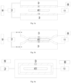
Figs. 1a and 1b are schematic structural diagrams of the low-temperature cooking machine according to a first embodiment of the present invention, illustrating a change process in which the flexible heating unit is deformed under the suction provided by the pump and thereby contacts with and heat the food, wherein the illustrated flexible heating unit partially surrounds the food cooking cavity; -
Figs. 2a and 2b are schematic structural diagrams of the low-temperature cooking machine according to a second embodiment not belonging to the present invention, illustrating a change process in which the flexible heating unit is deformed under the suction provided by the pump and thereby contacts with and heat the food, wherein the illustrated flexible heating unit is arranged around the food cooking cavity; -
Figs. 3a and 3b are schematic structural diagrams of the low-temperature cooking machine according to a third embodiment of the present invention, illustrating a change process in which the flexible heating unit is deformed under the pressure provided by the pump and thereby contacts with and heat the food, wherein the illustrated flexible heating unit partially surrounds the food cooking cavity; -
Figs. 4a and4b are schematic structural diagrams of the low-temperature cooking machine according to a fourth embodiment not belonging to the present invention, illustrating a change process in which the flexible heating unit is deformed under the pressure provided by the pump and thereby contacts with and heat the food, wherein the illustrated flexible heating unit is arranged around the food cooking cavity; -
Fig. 5 shows a schematic structural diagram of the low-temperature cooking machine according to the fourth embodiment of the present invention; and -
Fig. 6 shows another schematic structural diagram of the low-temperature cooking machine according to the fourth embodiment not belonging to the present invention. -
1 flexible heating unit 2 pump 3 flexible medium storage unit 4 food cooking cavity 5 base 6 upper cover 8 heating controller 41 food 9 air pump controller 10 pivot shaft 11 liquid heating bag 12 water heater 13 upper flexible heating unit 14 lower flexible heating unit 31 upper media storage area 32 lower media storage area 42 upper food cooking cavity 43 lower food cooking cavity - Hereunder some embodiments of the present invention will be detailed with reference to the accompanying drawings. It should be understood that the embodiments described herein are only provided to describe and explain the present invention rather than constitute any limitation to the present invention.
- In the present disclosure, unless otherwise specified, the words that denote directions or orientations, such as "above", "below", "top", and "bottom", etc., are usually used to describe the relative position relations among the components with respect to the direction shown in the accompanying drawings or the vertical, plumb, or gravity direction.
- To solve the problem that the existing low-temperature cooking machines require two products cooperating with each other (a thermostat water bath and a vacuum plastic package machine) and involve several operating procedures such as vacuum plastic packaging and water injection, etc. to realize food cooking, the present invention provides a novel low-temperature cooking machine, as shown in
Figs. 1a-1b . A similar low-temperature cooking machine not belonging to the present invention is shown inFig. 2a-2b . The low-temperature cooking machine comprises a flexible heating unit 1 (usually including aliquid heating bag 11 and awater heater 12, or seefigure 6 ) and apump 2 for providing pressure or suction to cause the flexible heating unit 1 to deform and contact with andheat food 41. - Apparently, the low-temperature cooking machine in the present invention is a novel cooking apparatus, in which, under the action of the
pump 2, the flexible heating unit 1 that serves as a heater can be deformed and directly contact withfood 41, so as to directly heat and cook thefood 41. - In the low-temperature cooking machine provided by the present invention, as shown in
Figs. 1a-1b and also in the low-temperature cooking machine shown inFig. 2a-2b , the low-temperature cooking machine comprises a food cooking cavity 4 for receiving thefood 41, wherein the flexible heating unit 1 at least partially surrounds the food cooking cavity 4; wherein the food cooking cavity 4 is a closed chamber, thepump 2 is an air pump for vacuuming the food cooking cavity 4, and the flexible heating unit 1 is in close contact with and heats thefood 41 under vacuum suction. Therefore, this technical scheme mainly employs air suction from the food cooking cavity 4; specifically, the user may directly put thefood 41 into the food cooking cavity 4, and thepump 2 pumps air out of the food cooking cavity 4, so that the flexible heating unit 1 is deformed under the suction and thereby closely contact with thefood 41, thus thefood 41 is in a vacuum-tight cooking environment and the flexible heating unit 1 that serves as a heater heats and cooks thefood 41. By vacuuming the food cooking cavity 4 with thepump 2, a vacuumed cooking state can be established between thefood 41 and the flexible heating unit 1 that serves as a heater, so as to replace a vacuum plastic package machine and avoid the use of a vacuum preservative bag. Besides, the flexible heating unit 1 may be a heating unit that requires replacing and replenishing a flexible heating material in time or may be a reusable heating unit. In the case that the flexible heating unit 1 is a reusable heating unit, both the operation step of adding water (for water bath) in time and the operation step of bagging and vacuuming in the existing low-temperature cooking machines can be omitted, thus the operation steps of cooking can be simplified. Apparently, with this technical scheme, the low-temperature cooking machine in the present invention is a novel apparatus and can replace the existing low-temperature cooking apparatus having a thermostat water bath and a vacuum plastic package machine. - To enable the flexible heating unit 1 to contact with and heat the
food 41, the flexible heating unit 1 may partially contact with thefood 41 or surround thefood 41, so as to heat the food. In this technical scheme, optionally the flexible heating unit 1 is arranged around the food cooking cavity 4 (seeFig. 2a-2b ), or the flexible heating unit 1 is at least arranged at two sides of the food 41 (seeFig. 1a-1b ), or the flexible heating unit 1 may be arranged at one side of thefood 41. - In view that water has high fluidity and can be heated quickly, the flexible heating unit 1 is a
liquid heating bag 11 connected with awater heater 12, theliquid heating bag 11 may be a flexible bag filled with water, and thewater heater 12 is connected with the flexible bag or arranged in the flexible bag. Of course, alternatively the flexible heating unit 1 may be made of a flexible material connected to other heating devices; for example, the flexible heating unit 1 may include a deformable flexible material such as silicone. - Specifically, the low-temperature cooking machine comprises a
base 5 and anupper cover 6 pivotally mounted on thebase 5, wherein the flexible heating unit 1 is arranged in a base cavity of thebase 5, and the food cooking cavity 4 is formed in the base cavity; wherein thefood 41 may be put into the food cooking cavity 4 when theupper cover 6 is pivotally opened, and theupper cover 6 encloses the food cooking cavity 4 when theupper cover 6 is pivotally closed. That is to say, when theupper cover 6 is pivotally opened around a pivot shaft (see thepivot shaft 10 inFigs. 5 and 6 ), the closed food cooking cavity 4 is opened at the same time, thereby thefood 41 can be placed into the food cooking cavity 4; after theupper cover 6 is pivotally closed on thebase 5, the food cooking cavity 4 becomes an enclosed chamber, so that thefood 41 in the food cooking cavity 4 can be vacuum-pumped with thepump 2 that serves as a suction pump. - Although it is a common practice to place the food cooking cavity 4 in the base cavity of the
base 5, in the low-temperature cooking machine in the present invention, the flexible heating unit 1 may also be arranged on the inner side of theupper cover 6, the food cooking cavity 4 may be arranged in the base cavity or in the upper cover cavity, or may be arranged in the base cavity and the upper cover cavity; in addition, the food cooking cavity 4 may be surrounded by the flexible heating unit 1 in theupper cover 5 and thebase 5, thereby thefood 41 can be fully wrapped by the flexible heating unit 1 that serves as a heater, so as to achieve a better cooking effect of thefood 41. - In the embodiment of low-temperature cooking machine in the present invention as shown in
Figs. 3a-3b and also in the low-temperature cooking machine not belonging to the present invention as shown inFig. 2a-2b , the low-temperature cooking machine comprises a flexiblemedium storage unit 3 connected with a medium pipe, wherein thepump body 2 is a pressure booster pump for pumping a pressurized medium toward the flexiblemedium storage unit 3 through the medium pipe, and the flexible heating unit 1 is pushed by the boosted pressure of the flexiblemedium storage unit 3 to closely contact with and heat thefood 41. It can be seen that the force for deforming the flexible heating unit 1 of the low-temperature cooking machine in this technical scheme mainly comes from the pressurization on the flexiblemedium storage unit 3 carried out by thepump 2 that serves as a pressure booster pump, and the flexible heating unit 1 is squeezed by the flexiblemedium storage unit 3 and thereby is deformed, so that the flexible heating unit 1 closely attaches to thefood 41 to be heated, and a vacuum-attached cooking effect is achieved between the flexible heating unit 1 and thefood 41. Likewise, it can be seen in this technical scheme, the low-temperature cooking machine is a novel apparatus and can replace an existing low-temperature cooking apparatus having a thermostat water bath and a vacuum plastic package machine. - As shown in
Figs. 5 and 6 , to enable the flexiblemedium storage unit 3 to squeeze and deform the flexible heating unit 1, the low-temperature cooking machine comprises abase 5, wherein the flexible heating unit 1, the flexiblemedium storage unit 3, and the food cooking cavity 4 for receiving thefood 41 are arranged in a base cavity of thebase 5, the flexible heating unit 1 at least partially surrounds the food cooking cavity 4, and the flexiblemedium storage unit 3 can at least partially contact with the flexible heating unit 1, so that the flexiblemedium storage unit 3 can drive the flexible heating unit 1 to move and deform. Likewise, the flexible heating unit 1 is aliquid heating bag 11 connected with awater heater 12. The flexiblemedium storage unit 3 may comprise a medium storage bag; usually, the flexiblemedium storage unit 3 may exist in the form of a self-sealing bag, thereby it is unnecessary to consider the problem of self-sealing of the bag in the process of pressurization on the flexiblemedium storage unit 3 carried out by thepump 2; in addition, the flexible bag of the flexiblemedium storage unit 3 may be made of various materials. The medium storage bag may be an air storage bag, which is to say, the medium may be gas, such as air; the flexible heating unit 1 is squeezed by external pressurization of the medium storage bag to deform so as to expel the air between the food cooking cavity 4 and thefood 41. - According to the common practice, the food cooking cavity 4 is mainly arranged in the base cavity. To that end, the base cavity is divided by the flexible heating unit 1 into a food cooking cavity 4 and a medium storage area that serves as the flexible
medium storage unit 3. That is to say, the flexiblemedium storage unit 3 exists in the form of a partitioned chamber, as shown inFigs. 5 and 6 , and the base cavity is partitioned. - In the low-temperature cooking machine in the present invention, in order to cook the
food 41 more uniformly and effectively, in the embodiment shown inFig. 5 , the flexible heating unit 1 comprises an upperflexible heating unit 13 and a lowerflexible heating unit 14, and the low-temperature cooking machine comprises aupper cover 6 pivotally mounted on thebase 5, the upperflexible heating unit 13 is arranged in an upper cover cavity of theupper cover 6, and the upper cover cavity is divided by the upperflexible heating unit 13 into an uppermedium storage area 31 and an upperfood cooking cavity 42; the base cavity is divided by the lowerflexible heating unit 14 into a lowerfood cooking cavity 43 and a lowermedium storage area 32; wherein the lowerfood cooking cavity 43, the lowerflexible heating unit 14 and the lowermedium storage area 32 are sequentially arranged in a separate manner from top to bottom in the base cavity; the uppermedium storage area 31, the upperflexible heating unit 13 and the upperfood cooking cavity 42 are sequentially arranged in a separate manner from top to bottom in the upper cover cavity. Therefore, thefood 41 can be placed in the food cooking cavity 4 composed of the upperfood cooking cavity 42 and the lowerfood cooking cavity 43, and the food cooking cavity 4 is a chamber enclosed by the upperflexible heating unit 13 and the lowerflexible heating unit 14, which are separate parts. The uppermedium storage area 31 and the lowermedium storage area 32 may be separate parts or may be formed integrally and communicate with each other. The medium storage area of the flexiblemedium storage unit 3 can be sealed; when the medium storage area is pressurized, the medium storage area can drive the flexible heating unit 1 to deform, so that the air in the food cooking cavity 4 is squeezed and expelled, thus a uniform vacuum and heated cooking environment for thefood 41 is ensured. - In another embodiment shown in
Fig. 6 not belonging to the present invention, the low-temperature cooking machine comprises anupper cover 6 pivotally mounted on thebase 5, wherein the medium storage area, the flexible heating unit 1 and the food cooking cavity 4 are transversely and sequentially arranged in a separate manner in the base cavity, and theupper cover 6 covers thebase 5 to enclose the medium storage area. - Of course, since this technical scheme employs an approach of passive exhausting by pressurizing the food cooking cavity 4, alternatively the food cooking cavity 4 may be an unsealed chamber. In the entire passive exhausting process, the food cooking cavity 4 is squeezed and exhausted, and finally a vacuum cooking environment can be established for the
food 41. - In order to make it easier and cheaper to pressurize the flexible
medium storage unit 3 with thepump 2 that serves as a pressure booster pump, the flexiblemedium storage unit 3 may be provided with an air intake passage as the medium pipe, and thepump 2 is an air pump that blows air to the flexiblemedium storage unit 3 through the air intake passage. - Furthermore, the low-temperature cooking machine in the present invention comprises an
air pump controller 9 for monitoring the air content in the food cooking cavity 4, so as to achieve a better vacuum cooking effect of thefood 41 by detecting the air content in the food cooking cavity 4 timely. - In addition, the low-temperature cooking machine in the present invention may further comprise a
heating controller 8 for monitoring the heating temperature of the flexible heating unit 1. Thus, the heating temperature of thefood 41 to be cooked is monitored in real time by detecting the heating temperature of the flexible heating unit 1, thereby a better control effect can be achieved, and the customer satisfaction can be improved. - Furthermore, the flexible heating unit 1 comprises a thermostatically controlled heating unit. A low-temperature cooking method employing thermostatically controlled heating can preserve the original flavor of the food, the fragrance of the spices and the primary color of the food to the greatest extent, thereby the user's experience and satisfaction can be improved.
- Usually, in the low-temperature cooking machine in the present invention, the cooking temperature of the low-temperature cooking machine may be selected to be 60°C~80°C, such as 60°C, 62°C, 65°C, 71°C, 78°C, 80°C, etc., and the cooking duration and temperature may be different for different foods and may be adjusted appropriately with the thermostatically controlled heating unit of the low-temperature cooking machine.
- Moreover, in order to ensure the hygienic condition of the
food 41 in the food cooking cavity 4, the interior of the food cooking cavity 4 may be washed or cleaned in advance before each time of cooking. In addition, other sterilizing devices, such as UV sterilizer, etc., may be arranged in the food cooking cavity 4. - It should be noted that the specific technical features described in above embodiments may be combined in any appropriate form, provided that there is no conflict. To avoid unnecessary repetition, the possible combinations are not described specifically in the present invention.
- The scope of protection of the invention is defined by the respective subject-matter of the appended claims.
Claims (9)
- A low-temperature cooking machine, comprising a flexible heating unit (1) and a pump (2) for providing pressure or suction to cause the flexible heating unit (1) to deform and contact with and heat a food (41), and comprising a food cooking cavity (4) for receiving the food (41), wherein the flexible heating unit (1) at least partially surrounds the food cooking cavity (4), and wherein the flexible heating unit (1) is a liquid heating bag (11) connected with a water heater (12), characterized in that the flexible heating unit (1) comprises a lower flexible heating unit (14) and an upper flexible heating unit (13), the low-temperature cooking machine comprises an upper cover (6) pivotally mounted on the base (5), the upper flexible heating unit (13) is arranged in an upper cover cavity of the upper cover (6), and the upper cover cavity is divided by the upper flexible heating unit (13) into an upper medium storage area (31) and an upper food cooking cavity (42); the base cavity is divided by the lower flexible heating unit (14) into a lower food cooking cavity (43) and a lower medium storage area (32);
wherein the lower food cooking cavity (43), the lower flexible heating unit (14) and the lower medium storage area (32) are sequentially arranged in a separate manner from top to bottom in the base cavity; the upper medium storage area (31), the upper flexible heating unit (13) and the upper food cooking cavity (42) are sequentially arranged in a separate manner from top to bottom in the upper cover cavity. - The low-temperature cooking machine according to claim 1, comprising a base (5) and an upper cover (6) pivotally mounted on the base (5), wherein the flexible heating unit (1) is arranged in a base cavity of the base (5), and the food cooking cavity (4) is formed in the base cavity;wherein the food (41) is able to be put into the food cooking cavity (4) when the upper cover (6) is pivotally opened, and the upper cover (6) encloses the food cooking cavity (4) when the upper cover (6) is pivotally closed;preferably, wherein the flexible heating unit (1) is arranged on the inner side of the upper cover (6).
- The low-temperature cooking machine according to claim 1, comprising a flexible medium storage unit (3) connected with a medium pipe, wherein the pump (2) is a pressure booster pump for pumping a pressurized medium toward the flexible medium storage unit (3) through the medium pipe, and the flexible heating unit (1) is pushed by the boosted pressure of the flexible medium storage unit (3) to closely contact with and heat the food (41).
- The low-temperature cooking machine according to claim 3, comprising a base (5), wherein the flexible heating unit (1), the flexible medium storage unit (3) and the food cooking cavity (4) for receiving the food (41) are arranged in a base cavity of the base (5), the flexible heating unit (1) at least partially surrounds the food cooking cavity (4), and the flexible medium storage unit (3) is able to at least partially contact with the flexible heating unit (1).
- The low-temperature cooking machine according to claim 4, wherein the flexible medium storage unit (3) is a medium storage bag.
- The low-temperature cooking machine according to claim 4, wherein the base cavity is divided by the flexible heating unit (1) into the food cooking cavity (4) and a medium storage area serving as the flexible medium storage unit (3).
- The low-temperature cooking machine according to claim 1, comprising an air pump controller (9) for monitoring the air content in the food cooking cavity (4).
- The low-temperature cooking machine according to claim any of claims 1-7, comprising a heating controller (8) for monitoring the heating temperature of the flexible heating unit (1), wherein the flexible heating unit (1) comprises a thermostatically controlled heating unit.
- The low-temperature cooking machine according to claim 1, wherein the cooking temperature of the low-temperature cooking machine is 60~80°C.
Applications Claiming Priority (2)
| Application Number | Priority Date | Filing Date | Title |
|---|---|---|---|
| CN201910266928.7A CN111772458B (en) | 2019-04-03 | 2019-04-03 | low temperature cooker |
| PCT/CN2019/096013 WO2020199419A1 (en) | 2019-04-03 | 2019-07-15 | Low-temperature cooking machine |
Publications (3)
| Publication Number | Publication Date |
|---|---|
| EP3932266A1 EP3932266A1 (en) | 2022-01-05 |
| EP3932266A4 EP3932266A4 (en) | 2022-05-25 |
| EP3932266B1 true EP3932266B1 (en) | 2025-01-22 |
Family
ID=72664602
Family Applications (1)
| Application Number | Title | Priority Date | Filing Date |
|---|---|---|---|
| EP19922879.2A Active EP3932266B1 (en) | 2019-04-03 | 2019-07-15 | Low-temperature cooking machine |
Country Status (4)
| Country | Link |
|---|---|
| US (1) | US12226041B2 (en) |
| EP (1) | EP3932266B1 (en) |
| CN (1) | CN111772458B (en) |
| WO (1) | WO2020199419A1 (en) |
Family Cites Families (11)
| Publication number | Priority date | Publication date | Assignee | Title |
|---|---|---|---|---|
| US8288692B2 (en) * | 2007-06-04 | 2012-10-16 | Liang Shengquan | Portable warmer |
| DE202010012775U1 (en) | 2010-09-17 | 2011-12-05 | Bernd Braukmann | Cooking device for vacuum technology |
| KR20130091814A (en) * | 2012-02-09 | 2013-08-20 | 주식회사 키친마더 | Manufacturing method of a vacuum roasting plate with heat pipe |
| EP2816939B1 (en) * | 2012-02-23 | 2017-10-11 | Oliso, Inc. | Apparatus for cooking food in an airtight bag |
| JP6552726B2 (en) * | 2015-05-11 | 2019-07-31 | イントロパック カンパニー リミテッド | Vacuum low temperature cooker |
| CN204743707U (en) * | 2015-06-06 | 2015-11-11 | 佛山市联盛达科技有限公司 | A low -temperature constant -temperature cook pot for cooking vacuum packaging food |
| WO2017197482A1 (en) * | 2016-05-17 | 2017-11-23 | Meier Hans J | Pressure-controlled sous-vide cooking method and appliance |
| CN105919444A (en) * | 2016-06-30 | 2016-09-07 | 靖西市秀美边城农业科技有限公司 | Vehicle-mounted heating bag |
| CN107898306B (en) * | 2017-11-20 | 2020-03-31 | 四川大学 | Method for heating fruits in winter |
| CN109171453A (en) * | 2018-08-20 | 2019-01-11 | 浙江工商大学 | A kind of novel evacuated low temperature cooking equipment |
| CN109463997A (en) * | 2019-01-22 | 2019-03-15 | 杭州老板电器股份有限公司 | Cooker and its application method |
-
2019
- 2019-04-03 CN CN201910266928.7A patent/CN111772458B/en active Active
- 2019-07-15 WO PCT/CN2019/096013 patent/WO2020199419A1/en not_active Ceased
- 2019-07-15 EP EP19922879.2A patent/EP3932266B1/en active Active
-
2021
- 2021-09-01 US US17/446,699 patent/US12226041B2/en active Active
Also Published As
| Publication number | Publication date |
|---|---|
| CN111772458B (en) | 2023-01-17 |
| EP3932266A4 (en) | 2022-05-25 |
| US20210393068A1 (en) | 2021-12-23 |
| US12226041B2 (en) | 2025-02-18 |
| WO2020199419A1 (en) | 2020-10-08 |
| EP3932266A1 (en) | 2022-01-05 |
| CN111772458A (en) | 2020-10-16 |
Similar Documents
| Publication | Publication Date | Title |
|---|---|---|
| US8012416B2 (en) | Thawing biological material using a sealed liquid bladder | |
| TWI666147B (en) | Manufacturing method of aseptic canning | |
| KR101529159B1 (en) | apparatus for packing food vessel | |
| DK2615953T3 (en) | Cooking device for vacuum cooking techniques | |
| KR100781674B1 (en) | Electric pressure cooker and its control method | |
| KR102356061B1 (en) | Vacuum cooking container and vacuum-low temperature cooking apparatus | |
| JP6838311B2 (en) | Cooker | |
| WO2022043414A1 (en) | Hygienic waste ingredient removal | |
| US12226041B2 (en) | Low-temperature cooking machine | |
| WO2000059821A1 (en) | Dispensing machine | |
| US20090214736A1 (en) | Chicken ring cooking device and method | |
| SE538970C2 (en) | Method and means for cooking and sterilization | |
| JP6740010B2 (en) | Vacuum packaging device and method for controlling vacuum packaging device | |
| CN109976198A (en) | Control method and system, the computer equipment and storage medium of cooker | |
| JPH04114611A (en) | Vacuum cooker | |
| JP2889961B2 (en) | Ultra high pressure cooking equipment | |
| KR102057004B1 (en) | Vacuum packing apparatus | |
| KR102654645B1 (en) | multifunctional packing machine | |
| JP3415827B2 (en) | Method for producing aseptic packed cooked rice | |
| JP3533500B2 (en) | Food heating method and device | |
| JP3026904B2 (en) | Method and apparatus for producing food by electric heating | |
| CN119840900A (en) | Vacuum sealing machine and sealing method | |
| JP2002176938A (en) | Method for producing aseptically-packed cooked rice | |
| KR20170118462A (en) | Vacuum packing apparatus | |
| JPH07100004B2 (en) | Manufacturing method of aseptic packed cooked rice |
Legal Events
| Date | Code | Title | Description |
|---|---|---|---|
| STAA | Information on the status of an ep patent application or granted ep patent |
Free format text: STATUS: THE INTERNATIONAL PUBLICATION HAS BEEN MADE |
|
| PUAI | Public reference made under article 153(3) epc to a published international application that has entered the european phase |
Free format text: ORIGINAL CODE: 0009012 |
|
| STAA | Information on the status of an ep patent application or granted ep patent |
Free format text: STATUS: REQUEST FOR EXAMINATION WAS MADE |
|
| 17P | Request for examination filed |
Effective date: 20210928 |
|
| AK | Designated contracting states |
Kind code of ref document: A1 Designated state(s): AL AT BE BG CH CY CZ DE DK EE ES FI FR GB GR HR HU IE IS IT LI LT LU LV MC MK MT NL NO PL PT RO RS SE SI SK SM TR |
|
| A4 | Supplementary search report drawn up and despatched |
Effective date: 20220428 |
|
| RIC1 | Information provided on ipc code assigned before grant |
Ipc: A47J 36/32 20060101ALI20220421BHEP Ipc: A47J 27/18 20060101ALI20220421BHEP Ipc: A47J 27/10 20060101ALI20220421BHEP Ipc: A47J 27/086 20060101ALI20220421BHEP Ipc: A47J 36/24 20060101ALI20220421BHEP Ipc: A47J 36/00 20060101ALI20220421BHEP Ipc: A47J 27/00 20060101AFI20220421BHEP |
|
| DAV | Request for validation of the european patent (deleted) | ||
| DAX | Request for extension of the european patent (deleted) | ||
| REG | Reference to a national code |
Ref country code: DE Ref legal event code: R079 Free format text: PREVIOUS MAIN CLASS: A47J0027000000 Ipc: A47J0036240000 Ref country code: DE Ref legal event code: R079 Ref document number: 602019065273 Country of ref document: DE Free format text: PREVIOUS MAIN CLASS: A47J0027000000 Ipc: A47J0036240000 |
|
| RIC1 | Information provided on ipc code assigned before grant |
Ipc: A47J 27/18 20060101ALI20231205BHEP Ipc: A47J 27/10 20060101ALI20231205BHEP Ipc: A47J 36/32 20060101ALI20231205BHEP Ipc: A47J 36/24 20060101AFI20231205BHEP |
|
| STAA | Information on the status of an ep patent application or granted ep patent |
Free format text: STATUS: EXAMINATION IS IN PROGRESS |
|
| 17Q | First examination report despatched |
Effective date: 20240215 |
|
| GRAP | Despatch of communication of intention to grant a patent |
Free format text: ORIGINAL CODE: EPIDOSNIGR1 |
|
| STAA | Information on the status of an ep patent application or granted ep patent |
Free format text: STATUS: GRANT OF PATENT IS INTENDED |
|
| INTG | Intention to grant announced |
Effective date: 20241018 |
|
| GRAS | Grant fee paid |
Free format text: ORIGINAL CODE: EPIDOSNIGR3 |
|
| GRAA | (expected) grant |
Free format text: ORIGINAL CODE: 0009210 |
|
| STAA | Information on the status of an ep patent application or granted ep patent |
Free format text: STATUS: THE PATENT HAS BEEN GRANTED |
|
| AK | Designated contracting states |
Kind code of ref document: B1 Designated state(s): AL AT BE BG CH CY CZ DE DK EE ES FI FR GB GR HR HU IE IS IT LI LT LU LV MC MK MT NL NO PL PT RO RS SE SI SK SM TR |
|
| REG | Reference to a national code |
Ref country code: GB Ref legal event code: FG4D |
|
| REG | Reference to a national code |
Ref country code: CH Ref legal event code: EP |
|
| REG | Reference to a national code |
Ref country code: IE Ref legal event code: FG4D |
|
| REG | Reference to a national code |
Ref country code: DE Ref legal event code: R096 Ref document number: 602019065273 Country of ref document: DE |
|
| REG | Reference to a national code |
Ref country code: NL Ref legal event code: MP Effective date: 20250122 |
|
| PG25 | Lapsed in a contracting state [announced via postgrant information from national office to epo] |
Ref country code: NL Free format text: LAPSE BECAUSE OF FAILURE TO SUBMIT A TRANSLATION OF THE DESCRIPTION OR TO PAY THE FEE WITHIN THE PRESCRIBED TIME-LIMIT Effective date: 20250122 |
|
| PG25 | Lapsed in a contracting state [announced via postgrant information from national office to epo] |
Ref country code: RS Free format text: LAPSE BECAUSE OF FAILURE TO SUBMIT A TRANSLATION OF THE DESCRIPTION OR TO PAY THE FEE WITHIN THE PRESCRIBED TIME-LIMIT Effective date: 20250422 |
|
| PG25 | Lapsed in a contracting state [announced via postgrant information from national office to epo] |
Ref country code: FI Free format text: LAPSE BECAUSE OF FAILURE TO SUBMIT A TRANSLATION OF THE DESCRIPTION OR TO PAY THE FEE WITHIN THE PRESCRIBED TIME-LIMIT Effective date: 20250122 |
|
| PG25 | Lapsed in a contracting state [announced via postgrant information from national office to epo] |
Ref country code: PL Free format text: LAPSE BECAUSE OF FAILURE TO SUBMIT A TRANSLATION OF THE DESCRIPTION OR TO PAY THE FEE WITHIN THE PRESCRIBED TIME-LIMIT Effective date: 20250122 |
|
| PG25 | Lapsed in a contracting state [announced via postgrant information from national office to epo] |
Ref country code: ES Free format text: LAPSE BECAUSE OF FAILURE TO SUBMIT A TRANSLATION OF THE DESCRIPTION OR TO PAY THE FEE WITHIN THE PRESCRIBED TIME-LIMIT Effective date: 20250122 |
|
| REG | Reference to a national code |
Ref country code: LT Ref legal event code: MG9D |
|
| PG25 | Lapsed in a contracting state [announced via postgrant information from national office to epo] |
Ref country code: IS Free format text: LAPSE BECAUSE OF FAILURE TO SUBMIT A TRANSLATION OF THE DESCRIPTION OR TO PAY THE FEE WITHIN THE PRESCRIBED TIME-LIMIT Effective date: 20250522 Ref country code: NO Free format text: LAPSE BECAUSE OF FAILURE TO SUBMIT A TRANSLATION OF THE DESCRIPTION OR TO PAY THE FEE WITHIN THE PRESCRIBED TIME-LIMIT Effective date: 20250422 |
|
| REG | Reference to a national code |
Ref country code: AT Ref legal event code: MK05 Ref document number: 1760774 Country of ref document: AT Kind code of ref document: T Effective date: 20250122 |
|
| PG25 | Lapsed in a contracting state [announced via postgrant information from national office to epo] |
Ref country code: HR Free format text: LAPSE BECAUSE OF FAILURE TO SUBMIT A TRANSLATION OF THE DESCRIPTION OR TO PAY THE FEE WITHIN THE PRESCRIBED TIME-LIMIT Effective date: 20250122 |
|
| PG25 | Lapsed in a contracting state [announced via postgrant information from national office to epo] |
Ref country code: PT Free format text: LAPSE BECAUSE OF FAILURE TO SUBMIT A TRANSLATION OF THE DESCRIPTION OR TO PAY THE FEE WITHIN THE PRESCRIBED TIME-LIMIT Effective date: 20250522 Ref country code: LV Free format text: LAPSE BECAUSE OF FAILURE TO SUBMIT A TRANSLATION OF THE DESCRIPTION OR TO PAY THE FEE WITHIN THE PRESCRIBED TIME-LIMIT Effective date: 20250122 |
|
| PG25 | Lapsed in a contracting state [announced via postgrant information from national office to epo] |
Ref country code: GR Free format text: LAPSE BECAUSE OF FAILURE TO SUBMIT A TRANSLATION OF THE DESCRIPTION OR TO PAY THE FEE WITHIN THE PRESCRIBED TIME-LIMIT Effective date: 20250423 Ref country code: BG Free format text: LAPSE BECAUSE OF FAILURE TO SUBMIT A TRANSLATION OF THE DESCRIPTION OR TO PAY THE FEE WITHIN THE PRESCRIBED TIME-LIMIT Effective date: 20250122 |
|
| PG25 | Lapsed in a contracting state [announced via postgrant information from national office to epo] |
Ref country code: AT Free format text: LAPSE BECAUSE OF FAILURE TO SUBMIT A TRANSLATION OF THE DESCRIPTION OR TO PAY THE FEE WITHIN THE PRESCRIBED TIME-LIMIT Effective date: 20250122 |
|
| PG25 | Lapsed in a contracting state [announced via postgrant information from national office to epo] |
Ref country code: SE Free format text: LAPSE BECAUSE OF FAILURE TO SUBMIT A TRANSLATION OF THE DESCRIPTION OR TO PAY THE FEE WITHIN THE PRESCRIBED TIME-LIMIT Effective date: 20250122 |
|
| PG25 | Lapsed in a contracting state [announced via postgrant information from national office to epo] |
Ref country code: SM Free format text: LAPSE BECAUSE OF FAILURE TO SUBMIT A TRANSLATION OF THE DESCRIPTION OR TO PAY THE FEE WITHIN THE PRESCRIBED TIME-LIMIT Effective date: 20250122 |
|
| PG25 | Lapsed in a contracting state [announced via postgrant information from national office to epo] |
Ref country code: DK Free format text: LAPSE BECAUSE OF FAILURE TO SUBMIT A TRANSLATION OF THE DESCRIPTION OR TO PAY THE FEE WITHIN THE PRESCRIBED TIME-LIMIT Effective date: 20250122 |
|
| PGFP | Annual fee paid to national office [announced via postgrant information from national office to epo] |
Ref country code: DE Payment date: 20250724 Year of fee payment: 7 |
|
| PG25 | Lapsed in a contracting state [announced via postgrant information from national office to epo] |
Ref country code: IT Free format text: LAPSE BECAUSE OF FAILURE TO SUBMIT A TRANSLATION OF THE DESCRIPTION OR TO PAY THE FEE WITHIN THE PRESCRIBED TIME-LIMIT Effective date: 20250122 |
|
| PGFP | Annual fee paid to national office [announced via postgrant information from national office to epo] |
Ref country code: GB Payment date: 20250722 Year of fee payment: 7 |
|
| PGFP | Annual fee paid to national office [announced via postgrant information from national office to epo] |
Ref country code: FR Payment date: 20250722 Year of fee payment: 7 |
|
| PG25 | Lapsed in a contracting state [announced via postgrant information from national office to epo] |
Ref country code: EE Free format text: LAPSE BECAUSE OF FAILURE TO SUBMIT A TRANSLATION OF THE DESCRIPTION OR TO PAY THE FEE WITHIN THE PRESCRIBED TIME-LIMIT Effective date: 20250122 Ref country code: CZ Free format text: LAPSE BECAUSE OF FAILURE TO SUBMIT A TRANSLATION OF THE DESCRIPTION OR TO PAY THE FEE WITHIN THE PRESCRIBED TIME-LIMIT Effective date: 20250122 |
|
| REG | Reference to a national code |
Ref country code: DE Ref legal event code: R097 Ref document number: 602019065273 Country of ref document: DE |
|
| PG25 | Lapsed in a contracting state [announced via postgrant information from national office to epo] |
Ref country code: RO Free format text: LAPSE BECAUSE OF FAILURE TO SUBMIT A TRANSLATION OF THE DESCRIPTION OR TO PAY THE FEE WITHIN THE PRESCRIBED TIME-LIMIT Effective date: 20250122 |
|
| PG25 | Lapsed in a contracting state [announced via postgrant information from national office to epo] |
Ref country code: SK Free format text: LAPSE BECAUSE OF FAILURE TO SUBMIT A TRANSLATION OF THE DESCRIPTION OR TO PAY THE FEE WITHIN THE PRESCRIBED TIME-LIMIT Effective date: 20250122 |
|
| PLBE | No opposition filed within time limit |
Free format text: ORIGINAL CODE: 0009261 |
|
| STAA | Information on the status of an ep patent application or granted ep patent |
Free format text: STATUS: NO OPPOSITION FILED WITHIN TIME LIMIT |
|
| REG | Reference to a national code |
Ref country code: CH Ref legal event code: L10 Free format text: ST27 STATUS EVENT CODE: U-0-0-L10-L00 (AS PROVIDED BY THE NATIONAL OFFICE) Effective date: 20251203 |
|
| 26N | No opposition filed |
Effective date: 20251023 |
|
| REG | Reference to a national code |
Ref country code: CH Ref legal event code: H13 Free format text: ST27 STATUS EVENT CODE: U-0-0-H10-H13 (AS PROVIDED BY THE NATIONAL OFFICE) Effective date: 20260224 |
|
| PG25 | Lapsed in a contracting state [announced via postgrant information from national office to epo] |
Ref country code: LU Free format text: LAPSE BECAUSE OF NON-PAYMENT OF DUE FEES Effective date: 20250715 |
|
| REG | Reference to a national code |
Ref country code: BE Ref legal event code: MM Effective date: 20250731 |
|
| PG25 | Lapsed in a contracting state [announced via postgrant information from national office to epo] |
Ref country code: BE Free format text: LAPSE BECAUSE OF NON-PAYMENT OF DUE FEES Effective date: 20250731 |
|
| PG25 | Lapsed in a contracting state [announced via postgrant information from national office to epo] |
Ref country code: CH Free format text: LAPSE BECAUSE OF NON-PAYMENT OF DUE FEES Effective date: 20250731 |