EP3932260A1 - Child carrier - Google Patents
Child carrier Download PDFInfo
- Publication number
- EP3932260A1 EP3932260A1 EP20184003.0A EP20184003A EP3932260A1 EP 3932260 A1 EP3932260 A1 EP 3932260A1 EP 20184003 A EP20184003 A EP 20184003A EP 3932260 A1 EP3932260 A1 EP 3932260A1
- Authority
- EP
- European Patent Office
- Prior art keywords
- child
- seat
- child carrier
- side support
- fixation
- Prior art date
- Legal status (The legal status is an assumption and is not a legal conclusion. Google has not performed a legal analysis and makes no representation as to the accuracy of the status listed.)
- Granted
Links
Images

Classifications
-
- A—HUMAN NECESSITIES
- A47—FURNITURE; DOMESTIC ARTICLES OR APPLIANCES; COFFEE MILLS; SPICE MILLS; SUCTION CLEANERS IN GENERAL
- A47D—FURNITURE SPECIALLY ADAPTED FOR CHILDREN
- A47D13/00—Other nursery furniture
- A47D13/02—Baby-carriers; Carry-cots
- A47D13/025—Baby-carriers; Carry-cots for carrying children in seated position
-
- A—HUMAN NECESSITIES
- A47—FURNITURE; DOMESTIC ARTICLES OR APPLIANCES; COFFEE MILLS; SPICE MILLS; SUCTION CLEANERS IN GENERAL
- A47D—FURNITURE SPECIALLY ADAPTED FOR CHILDREN
- A47D15/00—Accessories for children's furniture, e.g. safety belts or baby-bottle holders
- A47D15/005—Restraining devices, e.g. safety belts, contoured cushions or side bumpers
- A47D15/006—Restraining devices, e.g. safety belts, contoured cushions or side bumpers in chairs
Definitions
- the present disclosure relates generally to devices for carrying children. More particularly, the present disclosure relates to back-mounted child carriers.
- Child carriers have been used for years to carry children in such a way that the wearer has both hands free.
- Different child carriers are known in the prior art, for example the type used for hiking.
- such child carriers have a structure similar to that of a backpack. Instead of a luggage compartment, however, there is a seating arrangement on this backpack in which a child can be seated and carried.
- Child carriers known from the prior art have the problem, however, that it is difficult to optimally adjust the seating arrangement for children of different sizes.
- a child carrier according to independent claim 1 is provided.
- Advantageous further formations are subject of the dependent claims.
- a child carrier which can be easily adapted to children of different sizes.
- the adaptability of the child carrier according to the present disclosure may be such that when a seat height is adjusted, a thigh support portion is also adjusted at the same time. In this way an adjustment of the seat height results in a simultaneous adjustment of a support surface for supporting one of the child's thighs. Thus, when the seat height is adjusted, a further adjustment of the seat to the size of the child is achieved at the same time.
- a removable seating unit and a child carrier with such a removable seating unit is disclosed.
- the seating unit may comprise the adaptability to children of different sizes as described before or as described below in greater detail.
- a removable seating unit may not necessarily comprise the adaptability described herein or may only comprise selected features for adapting the seating unit and child carrier to children of different sizes, for example features allowing a height adjustment of the seating unit.
- the seating unit may be configured without the herein described thigh support portions although other features as described herein may be provided on the seating unit, if desired, in particular features relating to the detachable fixation of the seating unit or features allowing an adjustment of the seat height.
- a side support portion and a child carrier with such a side support portion are disclosed.
- the side support portion may be configured as described below.
- the side support portion may be provided on a seating unit which is fixedly mounted in the child carrier or may be provided on the removable seating unit as described herein. At least some features and members of the side support portion may be provided on the seating unit. If such a seating unit is removable, these features and members may also be removed from the child carrier together with the seating unit.
- Embodiments of child carriers, seating units and side support portions are described below and may include one or more of the features and characteristics described herein. The embodiments may be suitably combined.
- the child carrier may comprise a carrying structure.
- the carrying structure may have a front portion and a rear portion. Between the front portion and the rear portion an accommodating space may be defined. More precisely, the front portion and the rear portion may limit an accommodating space.
- a seating unit as described herein may be provided and in some embodiments, the child carrier may also comprise such a seating unit.
- the seating unit may be suspendable or suspended between the front portion and the rear portion.
- the seating unit may form a shell-like seat structure. At least one portion of the seat structure may be cup-shaped or bucket shaped.
- the seating unit may also comprise a seat middle portion, preferably a height-adjustable seat middle portion. The seat middle portion may be designed to support a child at a predetermined seat height.
- the seating unit may comprise thigh support portions.
- the thigh support portions may each provide a thigh support surface for a respective thigh of a child.
- the thigh support portions may be coupled to the seat middle portion in such a way that an adjustment of the seat height simultaneously results in an adjustment of the thigh support surface.
- At least the seat middle portion may be made from a flexible and non-elastic material, for example a fabric. In this way, the seat middle portion may be bendable but non-extendible in length.
- the seat middle portion may comprise a rear main seat portion.
- the rear main seat portion can support most of the child's body weight.
- the seat middle portion may further comprise a front secondary seat portion.
- the front secondary seat portion may extend forward from the rear main seat portion.
- the front secondary seat portion is located between the child's legs.
- the thigh support portions may be at least partially coupled to the front secondary seat portion.
- the seating unit may comprise a flexible surface structure.
- the flexible surface structure can define the seat structure.
- the flexible surface structure may be suspended so that the main seat portion is U-shaped when viewed from the front.
- the surface structure may be suspended in such a way that, when viewed from the front, the front secondary seat portion can form a W-shape together with the thigh support portions as the front secondary seat portion may be fixed forming a central upper portion of the W-shape and as the thigh support portions may be fixed on opposite sides of the front secondary seat portion forming the outer upper ends of the W-shape.
- the thigh support portions may define the lower portions of the W-shape thereby forming the recessed portions of the W-shape in which the thigh may be accommodated.
- Such recessed portions may be referred as leg loops, wrapping portions of the thigh support portions.
- Each of the thigh support portions can extend laterally away from opposite portions of the seat middle portion, forming a wrapping portion which may also be referred to as leg loop.
- Each wrapping portion may at least partially support an outer region of a child's thigh when the child is seated in the child carrier.
- At least each thigh support portion of the seating unit may comprise a fabric structure.
- Each thigh support portion may comprise a front edge portion facing the front portion of the carrying structure.
- the front edge portion may at least partially define a front end of the thigh support surface.
- the front edge portion may at least partially comprise a padding.
- the front edge portion may comprise a strap extending along the front edge portion. Such a strap may provide a reinforcement.
- Each thigh support portion may comprise a first end portion which is attached to the seat middle portion.
- the first end portion may, for example, be sewn on or may be integrally formed with the seat middle portion.
- each thigh support portion may comprise a second end portion attached to the child carrier at an fixation portion remote from the seat middle portion.
- the child carrier may comprise at least one side support portion, preferably two side support portions.
- Each side support portion protects a child seated in the child carrier from falling out sideways.
- the above mentioned fixation portion can be provided on one side support portion.
- At least one side support portion can comprise at least one first pivotable member.
- the first pivotable member may be pivotably held on the front portion of the carrying structure or the rear portion of the carrying structure at its first end portion and may be detachably coupled to the other portion of the front portion or the rear portion at its second end portion in order to at least partially laterally limit the accommodating space.
- at least one side support portion may be made of two parts.
- the two-part side support portion can comprise a second pivotable member which can be connected to the first pivotable member in an overlapping manner.
- a connection between the second pivotable member and the first pivotable member can be made with a connecting device, such as a buckle.
- the first pivotable member may comprise a receiving portion, such as in the form of a pocket, for receiving a free end portion of the second pivotable member.
- the second pivotable member may be stiffer than the first pivotable member.
- each side support portion may comprise at least one fixation member for fixing an accessory, for example a pillow.
- the at least one fixation member may be provided at an upper portion of the side support portion.
- the fixation member may comprise a fastening loop.
- a detachable seating unit is provided.
- the seating unit may be detachably mounted on the carrying structure. In this way it is possible to replace the seating unit if damaged or to remove it from the carrying structure for cleaning purposes.
- the seat middle portion may comprise a first fixation portion.
- the seat middle portion can be detachably coupled to the front portion via the first fixation portion.
- the first fixation portion preferably comprises a first member of a first positive locking connection.
- the first member can be a member of a buckle, such as a click or snap buckle.
- the seat middle portion may comprise a second fixation portion allowing the seat middle portion to be detachably coupled to the rear portion on the carrying structure.
- the second fixation portion preferably comprises a first member of a second positive locking connection, for example a member of a piping connection, for example a piping track or piping.
- the first member of the second positive connection may comprise a piping and the rear portion may comprise a track for receiving the piping.
- the track may be accessible via a lateral insertion opening formed in the carrying structure and comprising a dimension which allows the insertion of the first member, for example the piping, transversely to the longitudinal direction of the track, so that the first member can be laterally inserted into the track.
- the insertion opening may be provided at a predetermined distance from one end of the track. This allows the first member, when inserted into the track, to be at least partially accommodated on opposite sides of the insertion opening in the track so that the piping is prevented from coming loose from the track.
- the front portion of the carrying structure may comprise a height adjustment mechanism.
- the height adjustment mechanism allows to adjust the fixation height of the first fixation portion between a first height position and a second height position.
- the height adjustment mechanism can be configured such that the mounting height of the first fixation portion is steplessly adjustable.
- the height adjustment mechanism may comprise a closed loop.
- the closed loop may be guided on an upper guide and a lower guide.
- the upper guide may comprise a releasable locking arrangement with a self-locking function.
- the locking of the releasable locking arrangement may be released by an actuation of a user.
- the locking arrangement may comprise a release member, for example a lever, which may be actuated by the user to release the locking.
- the first fixation portion may be detachably coupled to the closed loop.
- a coupling member may be permanently attached to the closed loop.
- the fixation portion may cooperate with the coupling member to be detachably coupled to the coupling member.
- a padding for covering the height adjustment mechanism in particular for covering the upper guide including the releasable locking arrangement, may be provided.
- the carrying structure may comprise a rigid frame.
- the child carrier may be a frame-type child carrier.
- the frame may be made of aluminum profiles.
- the frame may be made of profiles made of other lightweight metals or alloys.
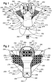
- Figure 1 shows a front view of a seating unit 200 according to an embodiment.
- Figure 1 shows the seating unit 200 positioned on a flat surface.
- Figure 1 shows an inner side of seating unit 200.
- Figure 2 shows a rear view of seating unit 200 according to the embodiment, positioned flat on a flat surface.
- Figure 2 shows an outer side of the seating unit 200.
- the seating unit 200 may comprise a flexible surface structure 201 defining the seating unit.
- the seating unit 200 comprises a seat middle portion 202.
- the seat middle portion 202 may comprise a rear main seat portion 203 and a front secondary seat portion 205.
- the seat middle portion 202 may comprise a back support portion 207, which may also be referred to as backrest portion.
- the seat middle portion 202 may be made form a flexible and non-elastic material, allowing it to bend but substantially preventing any length change of the seat middle portion.
- the transitions between the rear main seat portion 203 and the front secondary portion 205 may be seamless or may be provided by way of a seam.
- the main seat portion 203 may, according to one embodiment, the portion which bears most of the child's body weight when using the seating unit 200, meaning when a child is seated in the seating unit 200.
- the main seat portion 203 can therefore also be referred to as bottom support portion, as it is designed primarily to support the child's bottom.
- the front secondary seat portion 205 may extend forward from the rear main seat portion 203.
- the front secondary seat portion 205 may therefore be located in front of the rear main seat portion 203.
- the front secondary seat portion 205 may be located between the child's legs when using the seating unit 200.
- the main seat portion 203 and the secondary seat portion 205 can together form a saddle-like seat structure.
- the back support portion 207 may be provided on a side of the main seat portion 203 opposite the side where the front secondary seat portion 205 extends from the main seat portion 203.
- the seat middle portion 202 may be formed by the back support portion 207, the main seat portion 203 and the secondary seat portion 205 in this order in forward direction.
- the back support portion 207 comprises a strap assembly 230 which serves for securing the child in the seating unit 200.
- the strap assembly 230 may comprise two shoulder straps 231, 232 which can be coupled together by means of a two-part chest strap 233.
- the shoulder straps 231, 232 can be detachably attached to the back support portion 207.
- the shoulder straps 231, 232 may each comprise an upper end portion 234, 235 which can be detachably attached to the back support portion 207.
- each upper end portion 234, 235 may be coupled to the back support portion 207 by means of a buckle connection 236, 238 (see Figures 7 and 8 ).
- the buckle connections 236, 238 may be provided so that they are accessible from above to disconnect the upper end portions 234, 235 from the back support portion 207.
- each of the shoulder straps 231, 232 may comprise a lower end portion 239, 240 which can also be detachably attached to the back support portion 207.
- the lower end portions 239, 240 may be coupled to the back support portion 207 in a similar manner as the upper end portions 234, 235, for example with a buckle connection (not shown).
- the shoulder straps 231, 232 can be adjustable in length to adapt the shoulder straps 231, 232 to a child's size.
- a fixation portion 204 may be provided at the front secondary seat portion 205, more precisely at its front end portion 206, which may also be referred to as forward longitudinal end portion. More precisely, the fixation portion 204 is provided on the outer side of the secondary seat portion 205. According to the present embodiment, the fixation portion 204 may be provided for detachably attaching the seat middle portion 202 to a front portion 110 of a carrying structure 100 of a child carrier 1 as shown in Figure 3 and indicated in Figure 6 . The carrying structure 100 and the child carrier 1 will be described later in greater detail.
- the fixation portion 204 may comprise a coupling member 290 which is exemplary shown as a male part of a buckle arrangement.
- the coupling member 290 may comprise two lateral latching portions and can be releasably locked into a coupling member 101, for example a receiving portion embodied as a female part of the buckle arrangement, provided on the carrying structure 100.
- the coupling member 290 may be provided on the fixation portion by means of a strap 291.
- a padded member 292 may be provided on the strap to provide a soft chest support for the child.
- Two fixation portions 208 are provided on the back support portion 207 in order to detachably fix the back support portion 207 and thus the seat middle portion 202 to a rear portion 120 of the carrying structure 100 of the child carrier 1.
- Each of the two fixation portions 208 may comprise one member of a piping connection.
- the two fixation portions 208 each comprise a piping 209, which can be inserted through an opening 104 into a track 102 provided on the carrying structure 100 (see Figure 9 ).
- the piping 209 comprises a piping flap 210 which, in the embodiment shown, is attached, for example sewn, to an outside of the back support portion 207.
- the two fixation portions 208 are each located at a lateral end portion 211, 212 of the back support portion 207.
- piping 209 may extend along a respective lateral edge portion 213, 214.
- piping 209 may be configured to extend in a substantially vertical direction when inserted into the respective track 102 on the carrying structure 100.
- the rear portion 120 of the carrying structure 100 can be formed from profiles 113, for example aluminum profiles.
- the rear portion 120 of the carrying structure 100 may be in the form of an inverted U with two leg portions 114 extending downwardly from a common bridging portion 115 at the top of the rear portion 120.
- a track 102 may be formed in each leg portion.
- the track 102 is formed by a recess or groove which extends in the longitudinal direction of the leg portions and defines an accommodating space in which the aforementioned piping 209 is receivable and comprises a slot portion which is narrower than the accommodating space and is adapted to receive the aforementioned piping flap 210.
- Figure 11 shows an embodiment in which the seating unit 200 is arranged in the carrying structure 100. The piping 209 is inserted into the rear portion 120 and the piping flap 210 coupling the back support portion 207 to the rear member 120 is visible.
- an insertion opening 104 is formed in a predetermined area of the slot portion, as shown for example in Figure 9 .
- the insertion opening 104 can be located at a predetermined distance from one end of the track 102, so that when the piping 209 is inserted in the track 102, the piping 209 can be at least partially received in the track 102 on opposite sides of the insertion opening 104, so that the piping 209 is prevented from leaving the track 102 on its own through the insertion opening 104. This is prevented by a dead hole 105 which is formed in the end portion 103 of the track 102 and into which an end portion of the piping 209 can slide when the piping 209 is moved upwards.
- a seating unit 200 is provided, which can be detachably fastened to the carrying structure 100 by means of the fixation portion 204 and the fixation portions 208 in a suspended manner.
- the seating unit 200 can comprise two side support members 250, 260, which at least partially form a side support portion 300, 310 of the child carrier 1 as exemplary shown in Figure 3 .
- each side support member 250, 260 is pivotably attached to the back support portion 207 at its first end portion 251, 261. More precisely, in the embodiment shown, the first end portion 251, 261 of each side support component 250, 260 is pivotally coupled to one of the lateral edge portions 213, 214.
- Each side support member 250, 260 can also be referred to as a side wing, since these side support members 250, 260 extend away from lateral edge portions 213, 214 in a wing type manner.
- each side support member 250, 260 may be pivoted about the lateral edge portions 213, 214 in order to allow a user to seat a child in the seating unit 200.
- a lateral opening may be created by pivoting one of the side support members 250, 260 outwards.
- Each side support member 250, 260 may comprise an upper portion 252, 262 and a lower portion 253, 263.
- a fixation member 248 may be provided at the upper portions 252, 262 for the attachment of an accessory 400 as shown, for example, in Figures 7, 8 , 11 and 12 .
- the fixation member 248 is designed as a fixation loop. Hook members 402 of the accessory 400 can be hooked into the fixation loops to attach the accessory 400 to the fixation members 248.
- Such an accessory 400 is shown in Figure 12 in the form of a cushion which is U-shaped and when mounted extends from a side support member 250 over the front portion 110 of the carrying structure 100 onto the second side support member to cover the respective upper edge portions of the side support portions 300, 310 and the front portion 110.
- the side support portions 300, 310 may alternatively each comprise two side support members 250, 150 pivotably arranged such that they may overlap each other.
- the side support member 250 may be configured as described before.
- the side support member 150 may be pivotably coupled to the front portion 110 so that it may be pivoted so as to extend towards the rear portion 120 or such that its free end portion 154 is arranged closest to the rear portion 120.
- the side support member 250 may comprise a receiving portion 258, for example a pocket, for accommodating the free end portion 154 therein.
- the side support member 150 may comprise a higher rigidity than the side support member 250 in order to provide increased stiffness.
- the side support member 250 may comprise a padding on its inner side increasing the child's comfort.
- the side support member 250 may comprise a coupling member 259 which is engageable with a coupling member 152 provided on the side support member 150 as soon as the end portion 154 is inserted in the pocket 258. In this way, an openable and closable side support portion may be provided.
- the seating unit 200 may further comprise two thigh support portions 270, 280.
- the thigh support portions 270, 280 may comprise thigh support surfaces 271, 281 oriented upwards.
- Each of the thigh support portions 270, 280 may extend laterally away from opposite portions of the seat middle portion 202.
- the thigh support portions may form wrapping portions 279, 289 or leg loops configured to at least partially surround the thigh of a child.
- Each thigh support portion 270, 280 may comprise a first end portion 274, 284 which is attached to the seat middle portion 202.
- the first end portions 274, 284 are firmly attached to the seat middle portion 202.
- Each thigh support portion 270, 280 may comprise a second end portion 275, 285 which is attached to a fixation portion 256, 266 remote from the seat middle portion 202.
- the fixation portion 256, 266 is provided at the lower portions 253, 263 of the side support members 250, 260.
- the second end portions 275, 285 are attached to the lower portions 253, 263 of the side support members 250, 260.
- a front end of the fixation portion 256, 266 may be provided in the area of a front end portion 254, 264 of the side support members 250, 260.
- Coupling members 255, 265 may be provided on the front end portion 254, 264 and may be configured to directly or indirectly couple the side support members 250, 260 to the front portion 110, for example via a coupling member 183 provided on the front portion 110 (see Figure 4 ).
- the coupling members 255, 265 may comprise an element of a coupling arrangement, for example one of two mating members of a magnetic connection (see Figure 4 ), a hook and loop connection, or a buckle connection. If the coupling members 255, 265 are coupled to the front portion 110, the side support portions 300, 310 are active and able to prevent a child from laterally falling out of the child carrier 1. On the other hand, if the coupling members 255, 265 are decoupled, the support members 250, 260 may be pivoted outwards to render the inner space of the seat accessible.
- Each thigh support portion 270, 280 comprises a front edge portion 272, 282 which faces the front portion 110 of the carrying structure 100.
- the front edge portion 272, 282 may at least partially define a front edge portion of the thigh support surface 271, 281.
- Each front edge portion 272, 282 may comprise a padded portion 273, 283.
- the padded portions 273, 283 may improve the seating comfort of the child.
- the padded portions 273, 283 may extend from the seat middle portion 202 towards the side support members 250, 260.
- the front edge portion 272, 282 may extend inclined with respect to the longitudinal direction of the seat middle portion 202 as is shown in Figures 1 and 2 , in particular inclined with respect to a vertical longitudinal middle plane, and may at least partially protrude substantially straight from the seat middle portion when placed on a plane as shown in Figures 1 and 2 .
- the thigh support portions 270, 280 may form the above mentioned wrapping portions 279, 289 when the seating unit 200 is mounted to the carrying structure 100 in a suspended manner as shown in Figures 3 and 4 .
- the front edge portion 272, 282 extends from the seat middle portion 202, more precisely form the front secondary seat portion 205, up to the side support members 250, 260, for example to the lower portions 253, 263 of the side support members 250, 260, in particular at a front end portion 254, 264 of the side support members 250, 260.
- the front edge portion 272, 282 may comprise the padded portion 273, 283 as described before.
- the front edge portion 272, 282 may comprise a predetermined width and thus provide at least a portion of the thigh support surfaces 271, 281.
- a fabric structure 278, 288, for example a net or mesh structure, may be arranged between the front edge portion 272, 282, the lower portion 253, 263 and a lateral portion of the seat middle portion 202.
- the fabric structure 278, 288 may be omitted such that an opening is present between the latter mentioned parts instead of the fabric structure.
- the thigh support portions 270, 280 may be provided by means of a flexible surface structure, for example a fabric.
- the seat middle portion 202 and the thigh support portions 270, 280 may be formed from a flexible surface structure and may according to a modification be formed from a single flexible surface structure.
- the seat middle portion 202 and the thigh support portions 270, 280 may be integrally formed.
- the seat middle portion 202 may also be formed from a different material with different characteristics.
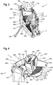
- Figure 3 shows a perspective view of the child carrier 1 with a carrying structure 100 and with a seating unit 200 attached to the carrying structure 100.
- Figure 4 shows a perspective view of the child carrier 1 shown in Figure 3 from obliquely above and in an open position in which a child can be seated in the seating unit 200.
- the seating unit 200 defines a cup-like or shell-like structure when it is mounted on the carrying structure 100.
- the seat middle portion 202 as well as the thigh support portions 270, 280 define a bag shaped interior space in which the child may be seated.
- the carrying structure comprises the front portion 110 and the rear portion 120.
- the child carrier 1 comprises a harness structure 2 with two shoulder straps 3, 4 as well as a hip belt 5.
- the harness structure is coupled to the front portion 110 and allows a user to carry the child carrier 1 on the back.
- a ground support 160 is coupled to the rear portion 120 by means of a pivot 170.
- the ground support 160 is pivotable between a use position, in which it is deployed and provides additional ground support portions for the child carrier 1 and a non-use position in which the ground support 160 is in a retracted position.
- Figure 3 shows the child carrier 1 in a use state in which the side support members 250, 260 are coupled to the front portion 110 and thereby provide side support portions 300, 310.
- thigh support portions 270, 280 are coupled to a lower portion of the side support members at one end and coupled to the seat middle portion 202 at the other end, wrapping portions 279, 280 are formed to support the thigh of a child.
- the wrapping portions provide thigh supporting surfaces 271, 281.
- the seating unit 200 is height adjustable.
- Figure 6 shows a schematic illustration of how the seating unit 200 is suspended in the carrying structure 100 and may be adjusted. More precisely, it is shown how the seat middle portion 202 is height-adjustable suspended between the front portion 110 and the rear portion 120.
- a height adjustment mechanism 160 is arranged on the front portion 110. The height adjustment mechanism 160 may allow to adjust the attachment height of the first fixation portion 204 between a first height position H1 and a second height position H2.
- the height adjustment mechanism 160 may comprise an upper guide 164 and a lower guide 168.
- a closed loop 162 is movably spanned between the upper guide 164 and the lower guide 166 such that it extends substantially in vertical direction.
- the upper guide 164 may comprise a releasable locking arrangement 170 having a self-locking function and the locking of the releasable locking arrangement 170 may be releasable by actuating a release member 172, for example a lever.
- a padded portion 174 for covering the height adjustment mechanism in particular for covering the upper guide including the releasable locking arrangement, may be provided.
- the padded portion 174 is hingedly held on the front portion 110 and shown in a state in which it is folded outward in order to allow a user to access the height adjustment mechanism 160.
- the height adjustment mechanism 160 may also be accessible from above without having to remove or pivot the padded portion 174 away.
- the height adjustment mechanism is accessible from above.
- the above-mentioned padded member 292 may be provided on the strap for covering the height adjustment mechanism or at least parts thereof.
- the front end of the seat middle section 202 is coupled to the loop portion provided on the side of the rear portion 120.
- the coupling member 290 as described before may be coupled to the loop portion.
- the height position of the coupling member 290 may be changed.
- Such a change of the position of the coupling member 290 in vertical direction results in a change of height of the secondary seat portion 205 and the main seat portion 203.
- the seat middle portion 202 is thus slightly unwound on one side. This not only results in the above mentioned change in height of the main seat portion 203 and the secondary seat portion 205 but also results in a horizontal position change of these portions since the seating unit 200 is fixedly held on the rear portion 120 by means of the second fixation portion 208. Therefore, lowering the coupling member 290 thus results in a position change of the secondary seat portion 205 towards the rear portion 120.
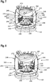
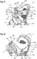
- FIG. 7 shows top views of the child carrier 1 according to the embodiment.
- Figure 7 shows a state in which the child carrier 1 is configured for carrying a small child.
- Figure 8 shows a state in which the child carrier 1 is configured for carrying a large child.
- the front edge portions 272, 282 of the thigh support portions 270, 280 are moved backwards towards the rear portion 120 in the state of Figure 8 and are moved forward towards the front portion 110 in the state of Figure 7 .
- the seating unit 200 is configured to provide a higher support compared to the configuration shown in Figure 8 . Therefore, the front edge portions 272, 282 are arranged closer to the front portion 110 in the state according to Figure 7 and are arranged at a greater distance from the front portion 110 in the state according to Figure 8 .
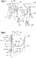
- the functional principle of the present disclosure may also be gleaned from the illustration according to Figure 5 in which on the left hand side it is shown how a smaller sized child 500 may be supported by the seating unit 200 and on the right hand side it is shown how a larger child 500 may be supported by the seating unit 200. It may be desirable to support a small child near the knee thus supporting substantially the entire or at least a knee end portion of its thighs 502, 504 from below and to support at least the bottom of the child. In this way, an ergonomic support of the child is possible even allowing to hold the child in the so called frog style according to which the thighs 502, 504 are angled more than 90 degrees.
- the front edge portions 272, 282 of the thigh support portions 270, 280 are raised, for example above a position at which the seat main portion 203 is arranged and closer to the front portion 110. Accordingly, a thigh support surface of increased size is provided allowing to support the child's thigh near the knee.
- the wrapping portions 279, 289 extend close to the knee.
- the front edge portions 272, 282 of the thigh support portions 270, 280 are lowered for example such that the front edge portions 272, 282 are lowered to a position at which the seat main portion 203 is arranged or to a lower position. This results in smaller sized thigh support surfaces which only support a portion of the child's thigh, for example less than half of the length of the child's thigh. This allows to carry the child in riding style.
- footrest portions 295, 296 may be provided on laterally outer ends of the front portion 110 for supporting the child's feet.
- a child carrier is configurable in a plurality of different configurations, for example with a seating unit that may be removable and/or which is height adjustable and/or which may comprise thigh support portions.
- a seating unit comprising only one of the latter characteristics may be provided.
- a removable seating unit comprising some of the above features regarding removability may be provided.
- the carrier may comprise at least one of the side support portions as described before in combination with a seating unit as disclosed herein.
- the side support portions may also be used on child carriers with any other seating unit. Examples of some exemplary configurations are provided below in addition to the configurations as presented in the appended claims. These exemplary configurations may be supplemented by or combined with features and characteristics as described before and/or as described in the appended claims.
- a first exemplary configuration of a child carrier 1 may comprise a carrying structure 100 and a seating unit 200, wherein the seating unit 200 is detachably mounted on the carrying structure 100.
- the carrying structure may comprise a front portion 110 and a rear portion 120 defining a receiving space 114 therebetween, and the seating unit 200 may be suspendable between the front portion 110 and the rear portion 120 under formation of a shell-like seat structure.
- the seating unit 200 may comprise a first fixation portion 204 at a forward end portion thereof and a second fixation portion 208 at a rear portion thereof.
- the first fixation portion 204 may be releasably coupled to the front portion 110 by means of a first positive connection or positive locking connection.
- the second fixation portion 204 may be releasably coupled to the rear portion 120 by means of a second positive connection or positive locking connection.
- a positive locking connection may be provided in different ways.
- a piping connection may be used.
- the seating unit may be optionally structured as described herein by way of the embodiments and may thus optionally comprise thigh support portions, for instance.
- a second basic configuration of a child carrier 1 may comprising a carrying structure 100, a seating unit 200 and at least one side support portions 300, 310 which protects a child sitting in the child carrier 1 from falling out sideways.
- the at least one side support portion 300, 310 may be formed in two parts, a first side support portion and a second side support portion, fixable to each other in an overlapping manner.
- One of the two parts may be directly or indirectly pivotably coupled to the front portion of the carrying structure and the other one of the two parts may be directly or indirectly pivotably coupled to the rear portion of the carrying structure.
- at least one of the two parts may be directly coupled to the seating unit.
- One of the two parts may comprise a receiving portion, for example a pocket, for receiving a free end portion of the other one of the two parts.
- One of the two parts may be stiffer than the other one or may generally comprise an increased stiffness in order to increase the overall rigidity of a side support portion.
- the two parts may be coupled by a connecting arrangement as described in the exemplary embodiments herein.
- the seating unit may be optionally structured as described herein by way of the embodiments and may thus optionally comprise thigh support portions, for instance.
Landscapes
- Health & Medical Sciences (AREA)
- General Health & Medical Sciences (AREA)
- Pediatric Medicine (AREA)
- Seats For Vehicles (AREA)
Abstract
Description
- The present disclosure relates generally to devices for carrying children. More particularly, the present disclosure relates to back-mounted child carriers.
- Child carriers have been used for years to carry children in such a way that the wearer has both hands free. Different child carriers are known in the prior art, for example the type used for hiking. Typically, such child carriers have a structure similar to that of a backpack. Instead of a luggage compartment, however, there is a seating arrangement on this backpack in which a child can be seated and carried. Child carriers known from the prior art have the problem, however, that it is difficult to optimally adjust the seating arrangement for children of different sizes.
- There is thus a need for an improved child carrier that addresses the above disadvantages.
- According to the present disclosure, a child carrier according to
independent claim 1 is provided. Advantageous further formations are subject of the dependent claims. - In addition, other desirable features and characteristics will become apparent from the summary and detailed description, and the appended claims, taken in conjunction with the accompanying drawings.
- According to an aspect, a child carrier is provided which can be easily adapted to children of different sizes. The adaptability of the child carrier according to the present disclosure may be such that when a seat height is adjusted, a thigh support portion is also adjusted at the same time. In this way an adjustment of the seat height results in a simultaneous adjustment of a support surface for supporting one of the child's thighs. Thus, when the seat height is adjusted, a further adjustment of the seat to the size of the child is achieved at the same time.
- According to a further aspect, a removable seating unit and a child carrier with such a removable seating unit is disclosed. The seating unit may comprise the adaptability to children of different sizes as described before or as described below in greater detail. However, a removable seating unit may not necessarily comprise the adaptability described herein or may only comprise selected features for adapting the seating unit and child carrier to children of different sizes, for example features allowing a height adjustment of the seating unit. For example, the seating unit may be configured without the herein described thigh support portions although other features as described herein may be provided on the seating unit, if desired, in particular features relating to the detachable fixation of the seating unit or features allowing an adjustment of the seat height.
- According to another aspect, a side support portion and a child carrier with such a side support portion are disclosed. The side support portion may be configured as described below. The side support portion may be provided on a seating unit which is fixedly mounted in the child carrier or may be provided on the removable seating unit as described herein. At least some features and members of the side support portion may be provided on the seating unit. If such a seating unit is removable, these features and members may also be removed from the child carrier together with the seating unit.
- Embodiments of child carriers, seating units and side support portions are described below and may include one or more of the features and characteristics described herein. The embodiments may be suitably combined.
- The child carrier may comprise a carrying structure. The carrying structure may have a front portion and a rear portion. Between the front portion and the rear portion an accommodating space may be defined. More precisely, the front portion and the rear portion may limit an accommodating space.
- In some embodiments, a seating unit as described herein may be provided and in some embodiments, the child carrier may also comprise such a seating unit. The seating unit may be suspendable or suspended between the front portion and the rear portion. The seating unit may form a shell-like seat structure. At least one portion of the seat structure may be cup-shaped or bucket shaped. The seating unit may also comprise a seat middle portion, preferably a height-adjustable seat middle portion. The seat middle portion may be designed to support a child at a predetermined seat height.
- In some embodiments, the seating unit may comprise thigh support portions. The thigh support portions may each provide a thigh support surface for a respective thigh of a child. The thigh support portions may be coupled to the seat middle portion in such a way that an adjustment of the seat height simultaneously results in an adjustment of the thigh support surface. At least the seat middle portion may be made from a flexible and non-elastic material, for example a fabric. In this way, the seat middle portion may be bendable but non-extendible in length.
- In some embodiments, the seat middle portion may comprise a rear main seat portion. When the child carrier is in use, i.e. when a child is seated in the child carrier, the rear main seat portion can support most of the child's body weight. In some embodiments, the seat middle portion may further comprise a front secondary seat portion. The front secondary seat portion may extend forward from the rear main seat portion. When using the child carrier, the front secondary seat portion is located between the child's legs. The thigh support portions may be at least partially coupled to the front secondary seat portion.
- In some embodiments, the seating unit may comprise a flexible surface structure. The flexible surface structure can define the seat structure. The flexible surface structure may be suspended so that the main seat portion is U-shaped when viewed from the front. Furthermore, the surface structure may be suspended in such a way that, when viewed from the front, the front secondary seat portion can form a W-shape together with the thigh support portions as the front secondary seat portion may be fixed forming a central upper portion of the W-shape and as the thigh support portions may be fixed on opposite sides of the front secondary seat portion forming the outer upper ends of the W-shape. The thigh support portions may define the lower portions of the W-shape thereby forming the recessed portions of the W-shape in which the thigh may be accommodated. Such recessed portions may be referred as leg loops, wrapping portions of the thigh support portions.
- Each of the thigh support portions can extend laterally away from opposite portions of the seat middle portion, forming a wrapping portion which may also be referred to as leg loop. Each wrapping portion may at least partially support an outer region of a child's thigh when the child is seated in the child carrier.
- At least each thigh support portion of the seating unit may comprise a fabric structure.
- Each thigh support portion may comprise a front edge portion facing the front portion of the carrying structure. The front edge portion may at least partially define a front end of the thigh support surface. The front edge portion may at least partially comprise a padding. The front edge portion may comprise a strap extending along the front edge portion. Such a strap may provide a reinforcement.
- Each thigh support portion may comprise a first end portion which is attached to the seat middle portion. The first end portion may, for example, be sewn on or may be integrally formed with the seat middle portion. In addition, each thigh support portion may comprise a second end portion attached to the child carrier at an fixation portion remote from the seat middle portion.
- In some embodiments, the child carrier may comprise at least one side support portion, preferably two side support portions. Each side support portion protects a child seated in the child carrier from falling out sideways. The above mentioned fixation portion can be provided on one side support portion.
- In some embodiments, at least one side support portion can comprise at least one first pivotable member. The first pivotable member may be pivotably held on the front portion of the carrying structure or the rear portion of the carrying structure at its first end portion and may be detachably coupled to the other portion of the front portion or the rear portion at its second end portion in order to at least partially laterally limit the accommodating space. In some embodiments, at least one side support portion may be made of two parts. The two-part side support portion can comprise a second pivotable member which can be connected to the first pivotable member in an overlapping manner. A connection between the second pivotable member and the first pivotable member can be made with a connecting device, such as a buckle. The first pivotable member may comprise a receiving portion, such as in the form of a pocket, for receiving a free end portion of the second pivotable member. The second pivotable member may be stiffer than the first pivotable member.
- In some embodiments, each side support portion may comprise at least one fixation member for fixing an accessory, for example a pillow. The at least one fixation member may be provided at an upper portion of the side support portion. For example, the fixation member may comprise a fastening loop.
- In some embodiments, a detachable seating unit is provided. The seating unit may be detachably mounted on the carrying structure. In this way it is possible to replace the seating unit if damaged or to remove it from the carrying structure for cleaning purposes.
- The seat middle portion may comprise a first fixation portion. The seat middle portion can be detachably coupled to the front portion via the first fixation portion. The first fixation portion preferably comprises a first member of a first positive locking connection. For example, the first member can be a member of a buckle, such as a click or snap buckle.
- The seat middle portion may comprise a second fixation portion allowing the seat middle portion to be detachably coupled to the rear portion on the carrying structure. The second fixation portion preferably comprises a first member of a second positive locking connection, for example a member of a piping connection, for example a piping track or piping.
- The first member of the second positive connection may comprise a piping and the rear portion may comprise a track for receiving the piping. The track may be accessible via a lateral insertion opening formed in the carrying structure and comprising a dimension which allows the insertion of the first member, for example the piping, transversely to the longitudinal direction of the track, so that the first member can be laterally inserted into the track. The insertion opening may be provided at a predetermined distance from one end of the track. This allows the first member, when inserted into the track, to be at least partially accommodated on opposite sides of the insertion opening in the track so that the piping is prevented from coming loose from the track.
- In some embodiments, the front portion of the carrying structure may comprise a height adjustment mechanism. The height adjustment mechanism allows to adjust the fixation height of the first fixation portion between a first height position and a second height position.
- The height adjustment mechanism can be configured such that the mounting height of the first fixation portion is steplessly adjustable. The height adjustment mechanism may comprise a closed loop. The closed loop may be guided on an upper guide and a lower guide. The upper guide may comprise a releasable locking arrangement with a self-locking function. The locking of the releasable locking arrangement may be released by an actuation of a user. In particular, the locking arrangement may comprise a release member, for example a lever, which may be actuated by the user to release the locking. The first fixation portion may be detachably coupled to the closed loop. In particular, a coupling member may be permanently attached to the closed loop. The fixation portion may cooperate with the coupling member to be detachably coupled to the coupling member. A padding for covering the height adjustment mechanism, in particular for covering the upper guide including the releasable locking arrangement, may be provided.
- In some embodiments, the carrying structure may comprise a rigid frame. Accordingly, the child carrier may be a frame-type child carrier. The frame may be made of aluminum profiles. Alternatively, the frame may be made of profiles made of other lightweight metals or alloys.
- Additional features and advantages of the above aspects and embodiments may be gleaned by the person skilled in the art from the following description of exemplary embodiments, which are not to be construed as limiting, however, drawing reference to the attached drawings.
- The present invention will hereinafter be described in conjunction with the following drawing figures, wherein like numerals denote like elements.
-
Figure 1 shows a front view of a seating unit according to an embodiment. -
Figure 2 shows a rear view of the seating unit shown inFigure 1 . -
Figure 3 shows a perspective view of a child carrier according to an embodiment. -
Figure 4 shows an upper part of the child carrier shown inFigure 3 . -
Figure 5 shows the support function principle according to the present disclosure. -
Figure 6 schematically shows a possible type of suspension of the seating unit on the carrying structure. -
Figure 7 shows a view of the child carrier from above, the child carrier comprising a setting for a small child. -
Figure 8 shows a view of the child carrier from above, the child carrier comprising a setting for a large child. -
Figure 9 schematically shows a rear portion of the carrying structure according to an embodiment. -
Figure 10 shows an enlarged sectional view of the rear portion of the carrying structure in the region of an insertion opening. -
Figure 11 shows a perspective view of a child carrier according to another embodiment. -
Figure 12 shows a perspective view of a child carrier according to another embodiment. - All figures are only schematic depictions of exemplary embodiments in which, in particular, distances and dimensional correlations are not presented to scale.
- The following detailed description is merely exemplary in nature and is not intended to limit application and uses. Furthermore, there is no intention to be bound by any theory presented in the preceding background or summary or the following detailed description.
-
Figure 1 shows a front view of aseating unit 200 according to an embodiment.Figure 1 shows theseating unit 200 positioned on a flat surface. In particular,Figure 1 shows an inner side ofseating unit 200.Figure 2 shows a rear view ofseating unit 200 according to the embodiment, positioned flat on a flat surface. In particular,Figure 2 shows an outer side of theseating unit 200. Theseating unit 200 may comprise aflexible surface structure 201 defining the seating unit. - The
seating unit 200 comprises a seatmiddle portion 202. The seatmiddle portion 202 may comprise a rearmain seat portion 203 and a frontsecondary seat portion 205. In addition, the seatmiddle portion 202 may comprise aback support portion 207, which may also be referred to as backrest portion. The seatmiddle portion 202 may be made form a flexible and non-elastic material, allowing it to bend but substantially preventing any length change of the seat middle portion. The transitions between the rearmain seat portion 203 and the frontsecondary portion 205 may be seamless or may be provided by way of a seam. - The
main seat portion 203 may, according to one embodiment, the portion which bears most of the child's body weight when using theseating unit 200, meaning when a child is seated in theseating unit 200. Themain seat portion 203 can therefore also be referred to as bottom support portion, as it is designed primarily to support the child's bottom. - The front
secondary seat portion 205 may extend forward from the rearmain seat portion 203. The frontsecondary seat portion 205 may therefore be located in front of the rearmain seat portion 203. The frontsecondary seat portion 205 may be located between the child's legs when using theseating unit 200. Themain seat portion 203 and thesecondary seat portion 205 can together form a saddle-like seat structure. - The
back support portion 207 may be provided on a side of themain seat portion 203 opposite the side where the frontsecondary seat portion 205 extends from themain seat portion 203. Thus the seatmiddle portion 202 may be formed by theback support portion 207, themain seat portion 203 and thesecondary seat portion 205 in this order in forward direction. Theback support portion 207 comprises astrap assembly 230 which serves for securing the child in theseating unit 200. - The
strap assembly 230 may comprise twoshoulder straps part chest strap 233. The shoulder straps 231, 232 can be detachably attached to theback support portion 207. The shoulder straps 231, 232 may each comprise anupper end portion back support portion 207. For example, eachupper end portion back support portion 207 by means of abuckle connection 236, 238 (seeFigures 7 and 8 ). Thebuckle connections upper end portions back support portion 207. In particular, thebuckle connections seat cushion portion 237 and thus, for example, be hidden or provided on the outside of theback support portion 207. In addition, each of theshoulder straps lower end portion back support portion 207. Thelower end portions back support portion 207 in a similar manner as theupper end portions shoulder straps - A
fixation portion 204 may be provided at the frontsecondary seat portion 205, more precisely at itsfront end portion 206, which may also be referred to as forward longitudinal end portion. More precisely, thefixation portion 204 is provided on the outer side of thesecondary seat portion 205. According to the present embodiment, thefixation portion 204 may be provided for detachably attaching the seatmiddle portion 202 to afront portion 110 of a carryingstructure 100 of achild carrier 1 as shown inFigure 3 and indicated inFigure 6 . The carryingstructure 100 and thechild carrier 1 will be described later in greater detail. In the present embodiment, thefixation portion 204 may comprise acoupling member 290 which is exemplary shown as a male part of a buckle arrangement. Thecoupling member 290 may comprise two lateral latching portions and can be releasably locked into acoupling member 101, for example a receiving portion embodied as a female part of the buckle arrangement, provided on the carryingstructure 100. Thecoupling member 290 may be provided on the fixation portion by means of astrap 291. A paddedmember 292 may be provided on the strap to provide a soft chest support for the child. - Two
fixation portions 208 are provided on theback support portion 207 in order to detachably fix theback support portion 207 and thus the seatmiddle portion 202 to arear portion 120 of the carryingstructure 100 of thechild carrier 1. Each of the twofixation portions 208 may comprise one member of a piping connection. In the embodiment shown, the twofixation portions 208 each comprise apiping 209, which can be inserted through anopening 104 into atrack 102 provided on the carrying structure 100 (seeFigure 9 ). The piping 209 comprises apiping flap 210 which, in the embodiment shown, is attached, for example sewn, to an outside of theback support portion 207. The twofixation portions 208 are each located at alateral end portion back support portion 207. - As shown in
Figure 2 , piping 209 may extend along a respectivelateral edge portion respective track 102 on the carryingstructure 100. As shown inFigure 9 , therear portion 120 of the carryingstructure 100 can be formed fromprofiles 113, for example aluminum profiles. Therear portion 120 of the carryingstructure 100 may be in the form of an inverted U with twoleg portions 114 extending downwardly from acommon bridging portion 115 at the top of therear portion 120. Atrack 102 may be formed in each leg portion. Thetrack 102 is formed by a recess or groove which extends in the longitudinal direction of the leg portions and defines an accommodating space in which theaforementioned piping 209 is receivable and comprises a slot portion which is narrower than the accommodating space and is adapted to receive theaforementioned piping flap 210.Figure 11 shows an embodiment in which theseating unit 200 is arranged in the carryingstructure 100. The piping 209 is inserted into therear portion 120 and thepiping flap 210 coupling theback support portion 207 to therear member 120 is visible. - To enable the piping 209 to be inserted laterally into the accommodating space, an
insertion opening 104 is formed in a predetermined area of the slot portion, as shown for example inFigure 9 . In the embodiment as shown inFigure 10 , theinsertion opening 104 can be located at a predetermined distance from one end of thetrack 102, so that when the piping 209 is inserted in thetrack 102, the piping 209 can be at least partially received in thetrack 102 on opposite sides of theinsertion opening 104, so that the piping 209 is prevented from leaving thetrack 102 on its own through theinsertion opening 104. This is prevented by adead hole 105 which is formed in theend portion 103 of thetrack 102 and into which an end portion of the piping 209 can slide when the piping 209 is moved upwards. - Thus, according to the present embodiment, a
seating unit 200 is provided, which can be detachably fastened to the carryingstructure 100 by means of thefixation portion 204 and thefixation portions 208 in a suspended manner. - Furthermore, the
seating unit 200 can comprise twoside support members side support portion child carrier 1 as exemplary shown inFigure 3 . In the embodiment shown, eachside support member back support portion 207 at itsfirst end portion first end portion side support component lateral edge portions side support member side support members lateral edge portions side support member lateral edge portions seating unit 200. In other words, a lateral opening may be created by pivoting one of theside support members - Each
side support member upper portion lower portion Figures 1 and 2 , afixation member 248 may be provided at theupper portions accessory 400 as shown, for example, inFigures 7, 8 ,11 and 12 . In the embodiment shown, thefixation member 248 is designed as a fixation loop.Hook members 402 of theaccessory 400 can be hooked into the fixation loops to attach theaccessory 400 to thefixation members 248. Such anaccessory 400 is shown inFigure 12 in the form of a cushion which is U-shaped and when mounted extends from aside support member 250 over thefront portion 110 of the carryingstructure 100 onto the second side support member to cover the respective upper edge portions of theside support portions front portion 110. - As is shown in
Figure 11 , theside support portions side support members 250, 150 pivotably arranged such that they may overlap each other. Theside support member 250 may be configured as described before. In addition, the side support member 150 may be pivotably coupled to thefront portion 110 so that it may be pivoted so as to extend towards therear portion 120 or such that itsfree end portion 154 is arranged closest to therear portion 120. Theside support member 250 may comprise a receivingportion 258, for example a pocket, for accommodating thefree end portion 154 therein. The side support member 150 may comprise a higher rigidity than theside support member 250 in order to provide increased stiffness. Theside support member 250 may comprise a padding on its inner side increasing the child's comfort. Theside support member 250 may comprise acoupling member 259 which is engageable with acoupling member 152 provided on the side support member 150 as soon as theend portion 154 is inserted in thepocket 258. In this way, an openable and closable side support portion may be provided. - The
seating unit 200 may further comprise twothigh support portions thigh support portions thigh support portions middle portion 202. In use, the thigh support portions may form wrappingportions thigh support portion first end portion middle portion 202. In the embodiment as shown, thefirst end portions middle portion 202. However, it is also possible to attach thefirst end portions middle portion 202, for example by means of a Velcro fastener or a buckle arrangement. - Each
thigh support portion second end portion fixation portion middle portion 202. In the embodiment shown, thefixation portion lower portions side support members second end portions lower portions side support members fixation portion front end portion side support members members front end portion side support members front portion 110, for example via acoupling member 183 provided on the front portion 110 (seeFigure 4 ). For example, thecoupling members Figure 4 ), a hook and loop connection, or a buckle connection. If thecoupling members front portion 110, theside support portions child carrier 1. On the other hand, if thecoupling members support members - Each
thigh support portion front edge portion front portion 110 of the carryingstructure 100. Thefront edge portion thigh support surface front edge portion portion padded portions padded portions middle portion 202 towards theside support members front edge portion middle portion 202 as is shown inFigures 1 and 2 , in particular inclined with respect to a vertical longitudinal middle plane, and may at least partially protrude substantially straight from the seat middle portion when placed on a plane as shown inFigures 1 and 2 . In this way, thethigh support portions portions seating unit 200 is mounted to the carryingstructure 100 in a suspended manner as shown inFigures 3 and 4 . - The
front edge portion middle portion 202, more precisely form the frontsecondary seat portion 205, up to theside support members lower portions side support members front end portion side support members front edge portion portion front edge portion fabric structure front edge portion lower portion middle portion 202. Depending on the size of thefront edge portion fabric structure thigh support portions middle portion 202 and thethigh support portions middle portion 202 and thethigh support portions middle portion 202 may also be formed from a different material with different characteristics. -
Figure 3 shows a perspective view of thechild carrier 1 with a carryingstructure 100 and with aseating unit 200 attached to the carryingstructure 100.Figure 4 shows a perspective view of thechild carrier 1 shown inFigure 3 from obliquely above and in an open position in which a child can be seated in theseating unit 200. In both Figures, it is visible that theseating unit 200 defines a cup-like or shell-like structure when it is mounted on the carryingstructure 100. The seatmiddle portion 202 as well as thethigh support portions - The carrying structure comprises the
front portion 110 and therear portion 120. Furthermore, thechild carrier 1 comprises aharness structure 2 with twoshoulder straps hip belt 5. The harness structure is coupled to thefront portion 110 and allows a user to carry thechild carrier 1 on the back. Aground support 160 is coupled to therear portion 120 by means of apivot 170. Theground support 160 is pivotable between a use position, in which it is deployed and provides additional ground support portions for thechild carrier 1 and a non-use position in which theground support 160 is in a retracted position. Furthermore,Figure 3 shows thechild carrier 1 in a use state in which theside support members front portion 110 and thereby provideside support portions thigh support portions middle portion 202 at the other end, wrappingportions thigh supporting surfaces - The
seating unit 200 is height adjustable.Figure 6 shows a schematic illustration of how theseating unit 200 is suspended in the carryingstructure 100 and may be adjusted. More precisely, it is shown how the seatmiddle portion 202 is height-adjustable suspended between thefront portion 110 and therear portion 120. Aheight adjustment mechanism 160 is arranged on thefront portion 110. Theheight adjustment mechanism 160 may allow to adjust the attachment height of thefirst fixation portion 204 between a first height position H1 and a second height position H2.Theheight adjustment mechanism 160 may comprise anupper guide 164 and alower guide 168. Aclosed loop 162 is movably spanned between theupper guide 164 and the lower guide 166 such that it extends substantially in vertical direction. Theupper guide 164 may comprise a releasable lockingarrangement 170 having a self-locking function and the locking of the releasable lockingarrangement 170 may be releasable by actuating arelease member 172, for example a lever. As is shown inFigure 11 , a paddedportion 174 for covering the height adjustment mechanism, in particular for covering the upper guide including the releasable locking arrangement, may be provided. InFigure 11 , the paddedportion 174 is hingedly held on thefront portion 110 and shown in a state in which it is folded outward in order to allow a user to access theheight adjustment mechanism 160. However, theheight adjustment mechanism 160 may also be accessible from above without having to remove or pivot the paddedportion 174 away. InFigure 4 , the height adjustment mechanism is accessible from above. Instead of the paddedportion 174, the above-mentionedpadded member 292 may be provided on the strap for covering the height adjustment mechanism or at least parts thereof. - The front end of the seat
middle section 202 is coupled to the loop portion provided on the side of therear portion 120. For example, thecoupling member 290 as described before may be coupled to the loop portion. Thus, by moving the loop, the height position of thecoupling member 290 may be changed. - Such a change of the position of the
coupling member 290 in vertical direction results in a change of height of thesecondary seat portion 205 and themain seat portion 203. The seatmiddle portion 202 is thus slightly unwound on one side. This not only results in the above mentioned change in height of themain seat portion 203 and thesecondary seat portion 205 but also results in a horizontal position change of these portions since theseating unit 200 is fixedly held on therear portion 120 by means of thesecond fixation portion 208. Therefore, lowering thecoupling member 290 thus results in a position change of thesecondary seat portion 205 towards therear portion 120. Since thethigh support portions main portion 202 as described before, thefront edge portions rear portion 120 so that the distance between thefront edge portions front portion 110 is increased. In this way, the size and location of the thigh support surfaces 271, 281 is also changed. The latter adjustment as is described in connection withFigure 6 is also clearly visible fromFigures 7 and 8. Figures 7 and 8 show top views of thechild carrier 1 according to the embodiment.Figure 7 shows a state in which thechild carrier 1 is configured for carrying a small child.Figure 8 shows a state in which thechild carrier 1 is configured for carrying a large child. As is directly visible, thefront edge portions thigh support portions rear portion 120 in the state ofFigure 8 and are moved forward towards thefront portion 110 in the state ofFigure 7 . In this way, available thigh supporting surfaces are changed. InFigure 7 , theseating unit 200 is configured to provide a higher support compared to the configuration shown inFigure 8 . Therefore, thefront edge portions front portion 110 in the state according toFigure 7 and are arranged at a greater distance from thefront portion 110 in the state according toFigure 8 . - The functional principle of the present disclosure may also be gleaned from the illustration according to
Figure 5 in which on the left hand side it is shown how a smallersized child 500 may be supported by theseating unit 200 and on the right hand side it is shown how alarger child 500 may be supported by theseating unit 200. It may be desirable to support a small child near the knee thus supporting substantially the entire or at least a knee end portion of itsthighs thighs first fixation portion 204 upwards, thefront edge portions thigh support portions main portion 203 is arranged and closer to thefront portion 110. Accordingly, a thigh support surface of increased size is provided allowing to support the child's thigh near the knee. The wrappingportions first fixation portion 204 is moved downwards, thefront edge portions thigh support portions front edge portions main portion 203 is arranged or to a lower position. This results in smaller sized thigh support surfaces which only support a portion of the child's thigh, for example less than half of the length of the child's thigh. This allows to carry the child in riding style. - In some configurations,
footrest portions front portion 110 for supporting the child's feet. - In summary, a child carrier is configurable in a plurality of different configurations, for example with a seating unit that may be removable and/or which is height adjustable and/or which may comprise thigh support portions. In particular, a seating unit comprising only one of the latter characteristics may be provided. For example, a removable seating unit comprising some of the above features regarding removability may be provided. Furthermore, the carrier may comprise at least one of the side support portions as described before in combination with a seating unit as disclosed herein. However, the side support portions may also be used on child carriers with any other seating unit. Examples of some exemplary configurations are provided below in addition to the configurations as presented in the appended claims. These exemplary configurations may be supplemented by or combined with features and characteristics as described before and/or as described in the appended claims.
- A first exemplary configuration of a
child carrier 1 may comprise a carryingstructure 100 and aseating unit 200, wherein theseating unit 200 is detachably mounted on the carryingstructure 100. The carrying structure may comprise afront portion 110 and arear portion 120 defining a receivingspace 114 therebetween, and theseating unit 200 may be suspendable between thefront portion 110 and therear portion 120 under formation of a shell-like seat structure. For that, theseating unit 200 may comprise afirst fixation portion 204 at a forward end portion thereof and asecond fixation portion 208 at a rear portion thereof. Thefirst fixation portion 204 may be releasably coupled to thefront portion 110 by means of a first positive connection or positive locking connection. Thesecond fixation portion 204 may be releasably coupled to therear portion 120 by means of a second positive connection or positive locking connection. A positive locking connection may be provided in different ways. For example, a piping connection may be used. The seating unit may be optionally structured as described herein by way of the embodiments and may thus optionally comprise thigh support portions, for instance. - A second basic configuration of a
child carrier 1 may comprising a carryingstructure 100, aseating unit 200 and at least oneside support portions child carrier 1 from falling out sideways. The at least oneside support portion - In conclusion a, it is pointed out that the terms like "comprising" or the like are not intended to rule out the provision of additional elements or steps. Let it further be noted that "a" or "an" do not preclude a plurality. In addition, features described in conjunction with the different embodiments can be combined with each other however desired. It is also noted that the reference numbers in the claims are not to be construed as limiting the scope of the claims. Moreover, while at least one exemplary embodiment has been presented in the foregoing summary and detailed description, it should be appreciated that a vast number of variations exist.
- It should also be appreciated that the exemplary embodiment or exemplary embodiments are only examples, and are not intended to limit the scope, applicability, or configuration in any way. Rather, the foregoing summary and detailed description will provide those skilled in the art with a convenient roadmap for implementing an exemplary embodiment, it being understood that various changes may be made in the function and arrangement of elements described in an exemplary embodiment without departing from the scope as set forth in the appended claims and their legal equivalents.
Claims (17)
- A child carrier (1) comprising:a carrying structure (100) having a front portion (110) and a rear portion (120) defining a receiving space (114) therebetween;a seating unit (200) suspended between said front portion (110) and said rear portion (120) under formation of a shell-like seat structure,wherein said seating unit (200) comprises a height-adjustable seat middle portion (202) adapted to support a child (500) at a predetermined seat height, andwherein said seating unit (200) comprises thigh support portions (270, 280) each providing a thigh support surface (271, 281) for a respective thigh of a child,wherein said thigh support portions (270, 280) are coupled to said seat middle portion (202) such that an adjustment of said seat height simultaneously results in an adjustment of said thigh support surface (271, 281).
- Child carrier (1) according to claim 1, wherein said seat middle portion (202) comprises a rear main seat portion (203) against which, in use, most of the body weight of the child (500) rests, a front secondary seat portion (205) extending forwardly from said rear main seat portion (203) and which, in use, is located between the legs of the child (500), said thigh support portions (270, 280) being at least partially coupled to said front secondary seat portion (205).
- Child carrier (1) according to claim 2, wherein said seating unit (200) comprises a flexible surface structure (201) defining the seat structure, wherein said surface structure (201) is suspended such that, when viewed from the front, the main seat portion (203) is U-shaped and the front secondary seat portion (205) can form a W-shape together with the thigh support portions (270, 280).
- Child carrier (1) according to one of claims 1 to 3, wherein each of said thigh support portions (270, 280) extends laterally away from opposite portions of said seat middle portion (202) thereby forming a wrapping portion (279, 289), each wrapping portion (279, 289) at least partially supporting an outer region of a thigh of the child when a child is seated in the child carrier (1).
- Child carrier (1) according to one of the preceding claims, wherein at least each thigh support portion (270, 280) comprises a fabric structure (278, 288).
- Child carrier (1) according to one of the preceding claims, each thigh support portion (270, 280) having a front edge portion (272, 282) facing the front portion (110) and at least partially defining a front end of the thigh support surface (271, 281), wherein the front edge portion (272, 282) may comprise a padded portion (273, 283) and/or may comprise a strap extending along said front edge portion (272, 282).
- Child carrier (1) according to one of the preceding claims, each thigh support portion (270, 280) comprising a first end portion (274, 284) fixed, in particular sewn or formed integrally with said seat middle portion (202), and a second end portion (275, 285) fixed to said child carrier (1) at an fixation portion (256, 266) located remote from said seat middle portion (202)
- Child carrier (1) according to claim 7, further comprising two side support portions (300, 310) which protect a child sitting in the child carrier (1) from falling out sideways.
- Child carrier (1) according to claim 8, wherein at least one side support portion (300) comprises at least one first pivotable side support member (250, 260) which is pivotably held at its first end portion (251, 261) at the front portion (110) or the rear portion (120) and which can be detachably coupled to the other portion of the front portion (110) or the rear portion (120) at its second end portion (254, 255) in order to at least partially limit the receiving space (114) laterally, wherein at least one side support portion (300) can be formed in two parts, wherein a second pivotable side support member (150) can be provided that can be connected with the first pivotable side support member (250, 260) in overlapping manner, for example with a connecting arrangement (259, 152) such as a buckle, wherein for example the first pivotable side support member (250, 260) can comprise a receiving portion (258), in particular a pocket, for receiving a free end portion (154) of the second pivotable side support member (150), and wherein the second pivotable side support member (150) can be configured to be stiffer than the first pivotable side support member (250).
- Child carrier (1) according to claim 9, wherein said side support portion (300) comprises at least one fixation member (248) for fastening an accessory (400), for example a pillow, wherein said at least one fixation member (248) is preferably provided on an upper portion (2) of said side support portion (1), and wherein said at least one fixation member (248) may be a fastening loop.
- Child carrier (1) according to one of the preceding claims, wherein the seating unit (200) is detachably mounted on said carrying structure (100).
- Child carrier (1) according to claim 11, wherein the seat middle portion (202) comprises a first fixation portion (204) for detachably coupling the seat middle portion (202) to the front portion (110), wherein said first fixation portion (204) preferably comprises a first member (290) of a first positive connection, for example a member of a buckle, for example of a click or snap buckle.
- Child carrier (1) according to claim 12, wherein the front portion (110) comprises a height adjustment mechanism (160) which allows to adjust the attachment height of the first fixation portion (204) between a first height position (H1) and a second height position (H2).
- Child carrier (1) according to claim 13, wherein said height adjustment mechanism (160) is adapted to steplessly adjust the attachment height of said first fixation portion (204), wherein said height adjustment mechanism (160) may comprise a closed loop (162) guided on an upper guide (164) and a lower guide (168), wherein the upper guide (164) may comprise a releasable locking arrangement (170) having a self-locking function and the locking of the releasable locking arrangement (170) may be releasable by actuating a release member (172), for example a lever, wherein the first fixation portion (204) is detachably coupled to the closed loop (162), for example in cooperation with a coupling member (101) which is fixedly coupled to the closed loop (162).
- Child carrier (1) according to one of claims 11 to 14, wherein the seat middle portion (202) comprises a second fixation portion (208) by means of which the seat middle portion (202) is detachably coupled to the rear portion (120), wherein the second fixation portion (208) preferably comprises a first member (209) of a second positive connection, for example a member of a piping connection, for example a piping track or a piping.
- Child carrier (1) according to claim 15, wherein said first member (209) of said second positive-locking connection comprises a piping and said rear portion (120) comprises a track (102) for receiving said piping (209), wherein said track (102) is accessible via a lateral insertion opening (104) which is formed in the carrying structure (100) and has a dimension that permits the insertion of said first member (209), for example said piping, transversely to the longitudinal extension direction of said track (102), so that said first member (209) can be inserted laterally into said track (102), wherein said insertion opening (104) can be provided at a predetermined distance from an end of said track (102) so that when said first member (209) is inserted into said track (102), said first member (209) can be at least partially received in said track (102) on opposite sides of said insertion opening (104) so that said piping (209) is prevented from coming loose from said track (102).
- Child carrier (1) according to one of the preceding claims, wherein said carrying structure (100) comprises a rigid frame which may comprise aluminum profiles.
Priority Applications (3)
| Application Number | Priority Date | Filing Date | Title |
|---|---|---|---|
| EP20184003.0A EP3932260B1 (en) | 2020-07-03 | 2020-07-03 | Child carrier |
| US17/362,426 US12274375B2 (en) | 2020-07-03 | 2021-06-29 | Child carrier |
| US19/077,835 US20250204700A1 (en) | 2020-07-03 | 2025-03-12 | Child carrier |
Applications Claiming Priority (1)
| Application Number | Priority Date | Filing Date | Title |
|---|---|---|---|
| EP20184003.0A EP3932260B1 (en) | 2020-07-03 | 2020-07-03 | Child carrier |
Publications (2)
| Publication Number | Publication Date |
|---|---|
| EP3932260A1 true EP3932260A1 (en) | 2022-01-05 |
| EP3932260B1 EP3932260B1 (en) | 2025-12-03 |
Family
ID=71514948
Family Applications (1)
| Application Number | Title | Priority Date | Filing Date |
|---|---|---|---|
| EP20184003.0A Active EP3932260B1 (en) | 2020-07-03 | 2020-07-03 | Child carrier |
Country Status (2)
| Country | Link |
|---|---|
| US (2) | US12274375B2 (en) |
| EP (1) | EP3932260B1 (en) |
Family Cites Families (6)
| Publication number | Priority date | Publication date | Assignee | Title |
|---|---|---|---|---|
| US5868292A (en) * | 1995-11-03 | 1999-02-09 | Gerry Baby Products | Frame carrier for children |
| US6318608B1 (en) * | 1999-08-13 | 2001-11-20 | American Recreation Products, Inc. | Child carrier |
| FR2822042B1 (en) * | 2001-03-13 | 2003-05-16 | Lafuma Sa | MODULAR BABY CARRIER |
| FR2837078B1 (en) * | 2002-03-15 | 2005-12-02 | Lafuma Sa | ARRANGEMENT FOR ADJUSTING THE PORTAGE OF A BACKPACK |
| EP2915458B1 (en) * | 2014-03-03 | 2016-07-20 | Thule IP AB | Carrier frame for a child carrier |
| NL2014948B1 (en) * | 2015-06-10 | 2017-02-15 | Minimonkey B V | Sling type child carrier. |
-
2020
- 2020-07-03 EP EP20184003.0A patent/EP3932260B1/en active Active
-
2021
- 2021-06-29 US US17/362,426 patent/US12274375B2/en active Active
-
2025
- 2025-03-12 US US19/077,835 patent/US20250204700A1/en active Pending
Non-Patent Citations (1)
| Title |
|---|
| THULEBRINGYOURLIFE: "Child carrier backpack - Thule Sapling Elite", 9 March 2015 (2015-03-09), pages 1 - 2, XP054981022, Retrieved from the Internet <URL:https://www.youtube.com/watch?v=V8c45_57mHs> [retrieved on 20201020] * |
Also Published As
| Publication number | Publication date |
|---|---|
| US20220000276A1 (en) | 2022-01-06 |
| US12274375B2 (en) | 2025-04-15 |
| US20250204700A1 (en) | 2025-06-26 |
| EP3932260B1 (en) | 2025-12-03 |
Similar Documents
| Publication | Publication Date | Title |
|---|---|---|
| US7886946B2 (en) | Baby carrier | |
| JP6859386B2 (en) | Child carrier | |
| EP0818965B1 (en) | Combination backpack and chair | |
| US8028871B2 (en) | Baby carrier | |
| CN108697246B (en) | Adjustable children's backpack | |
| AU634050B2 (en) | Convertible child carrier | |
| KR20210157366A (en) | Adjustable child carrier with multiple carry orientations | |
| US20150282639A1 (en) | Baby carrier with removable seat | |
| US20090321481A1 (en) | Backpack load carrying system | |
| CN110035677A (en) | Adjustable child carrier with multiple carrying orientations | |
| US11470949B2 (en) | Binocular harness system | |
| US20220015552A1 (en) | Child carrier sling | |
| US12274375B2 (en) | Child carrier | |
| US20100038953A1 (en) | Infant chair harness | |
| CN113395919A (en) | Baby carrier | |
| GB2563673A (en) | Detachable baby carrier | |
| NO349005B1 (en) | Backpack with a child seat secure device | |
| MXPA97007075A (en) | Combination of backpack and yes | |
| GB2515120A (en) | A carrier device | |
| HK1262861A1 (en) | Adjustable child carrier |
Legal Events
| Date | Code | Title | Description |
|---|---|---|---|
| PUAI | Public reference made under article 153(3) epc to a published international application that has entered the european phase |
Free format text: ORIGINAL CODE: 0009012 |
|
| STAA | Information on the status of an ep patent application or granted ep patent |
Free format text: STATUS: THE APPLICATION HAS BEEN PUBLISHED |
|
| AK | Designated contracting states |
Kind code of ref document: A1 Designated state(s): AL AT BE BG CH CY CZ DE DK EE ES FI FR GB GR HR HU IE IS IT LI LT LU LV MC MK MT NL NO PL PT RO RS SE SI SK SM TR |
|
| B565 | Issuance of search results under rule 164(2) epc |
Effective date: 20201102 |
|
| STAA | Information on the status of an ep patent application or granted ep patent |
Free format text: STATUS: REQUEST FOR EXAMINATION WAS MADE |
|
| 17P | Request for examination filed |
Effective date: 20220704 |
|
| RBV | Designated contracting states (corrected) |
Designated state(s): AL AT BE BG CH CY CZ DE DK EE ES FI FR GB GR HR HU IE IS IT LI LT LU LV MC MK MT NL NO PL PT RO RS SE SI SK SM TR |
|
| P01 | Opt-out of the competence of the unified patent court (upc) registered |
Effective date: 20230528 |
|
| STAA | Information on the status of an ep patent application or granted ep patent |
Free format text: STATUS: EXAMINATION IS IN PROGRESS |
|
| 17Q | First examination report despatched |
Effective date: 20240325 |
|
| GRAP | Despatch of communication of intention to grant a patent |
Free format text: ORIGINAL CODE: EPIDOSNIGR1 |
|
| STAA | Information on the status of an ep patent application or granted ep patent |
Free format text: STATUS: GRANT OF PATENT IS INTENDED |
|
| GRAS | Grant fee paid |
Free format text: ORIGINAL CODE: EPIDOSNIGR3 |
|
| GRAA | (expected) grant |
Free format text: ORIGINAL CODE: 0009210 |
|
| STAA | Information on the status of an ep patent application or granted ep patent |
Free format text: STATUS: THE PATENT HAS BEEN GRANTED |
|
| INTG | Intention to grant announced |
Effective date: 20251002 |
|
| AK | Designated contracting states |
Kind code of ref document: B1 Designated state(s): AL AT BE BG CH CY CZ DE DK EE ES FI FR GB GR HR HU IE IS IT LI LT LU LV MC MK MT NL NO PL PT RO RS SE SI SK SM TR |
|
| REG | Reference to a national code |
Ref country code: CH Ref legal event code: F10 Free format text: ST27 STATUS EVENT CODE: U-0-0-F10-F00 (AS PROVIDED BY THE NATIONAL OFFICE) Effective date: 20251203 Ref country code: GB Ref legal event code: FG4D |
|
| REG | Reference to a national code |
Ref country code: DE Ref legal event code: R096 Ref document number: 602020063101 Country of ref document: DE |
|
| REG | Reference to a national code |
Ref country code: IE Ref legal event code: FG4D |
|
| REG | Reference to a national code |
Ref country code: SE Ref legal event code: TRGR |
|
| REG | Reference to a national code |
Ref country code: NL Ref legal event code: MP Effective date: 20251203 |
|
| PG25 | Lapsed in a contracting state [announced via postgrant information from national office to epo] |
Ref country code: ES Free format text: LAPSE BECAUSE OF FAILURE TO SUBMIT A TRANSLATION OF THE DESCRIPTION OR TO PAY THE FEE WITHIN THE PRESCRIBED TIME-LIMIT Effective date: 20251203 |
|
| REG | Reference to a national code |
Ref country code: LT Ref legal event code: MG9D |
|
| PG25 | Lapsed in a contracting state [announced via postgrant information from national office to epo] |
Ref country code: NO Free format text: LAPSE BECAUSE OF FAILURE TO SUBMIT A TRANSLATION OF THE DESCRIPTION OR TO PAY THE FEE WITHIN THE PRESCRIBED TIME-LIMIT Effective date: 20260303 |
|
| PG25 | Lapsed in a contracting state [announced via postgrant information from national office to epo] |
Ref country code: FI Free format text: LAPSE BECAUSE OF FAILURE TO SUBMIT A TRANSLATION OF THE DESCRIPTION OR TO PAY THE FEE WITHIN THE PRESCRIBED TIME-LIMIT Effective date: 20251203 Ref country code: HR Free format text: LAPSE BECAUSE OF FAILURE TO SUBMIT A TRANSLATION OF THE DESCRIPTION OR TO PAY THE FEE WITHIN THE PRESCRIBED TIME-LIMIT Effective date: 20251203 |
|
| PG25 | Lapsed in a contracting state [announced via postgrant information from national office to epo] |
Ref country code: RS Free format text: LAPSE BECAUSE OF FAILURE TO SUBMIT A TRANSLATION OF THE DESCRIPTION OR TO PAY THE FEE WITHIN THE PRESCRIBED TIME-LIMIT Effective date: 20260303 |
|
| PG25 | Lapsed in a contracting state [announced via postgrant information from national office to epo] |
Ref country code: PL Free format text: LAPSE BECAUSE OF FAILURE TO SUBMIT A TRANSLATION OF THE DESCRIPTION OR TO PAY THE FEE WITHIN THE PRESCRIBED TIME-LIMIT Effective date: 20251203 |
|
| PG25 | Lapsed in a contracting state [announced via postgrant information from national office to epo] |
Ref country code: LV Free format text: LAPSE BECAUSE OF FAILURE TO SUBMIT A TRANSLATION OF THE DESCRIPTION OR TO PAY THE FEE WITHIN THE PRESCRIBED TIME-LIMIT Effective date: 20251203 |