EP3932241A1 - Shoe - Google Patents
Shoe Download PDFInfo
- Publication number
- EP3932241A1 EP3932241A1 EP19917084.6A EP19917084A EP3932241A1 EP 3932241 A1 EP3932241 A1 EP 3932241A1 EP 19917084 A EP19917084 A EP 19917084A EP 3932241 A1 EP3932241 A1 EP 3932241A1
- Authority
- EP
- European Patent Office
- Prior art keywords
- air
- shoe
- sucking out
- air sucking
- out portion
- Prior art date
- Legal status (The legal status is an assumption and is not a legal conclusion. Google has not performed a legal analysis and makes no representation as to the accuracy of the status listed.)
- Granted
Links
Images





Classifications
-
- A—HUMAN NECESSITIES
- A43—FOOTWEAR
- A43B—CHARACTERISTIC FEATURES OF FOOTWEAR; PARTS OF FOOTWEAR
- A43B7/00—Footwear with health or hygienic arrangements
- A43B7/06—Footwear with health or hygienic arrangements ventilated
- A43B7/08—Footwear with health or hygienic arrangements ventilated with air-holes, with or without closures
- A43B7/082—Footwear with health or hygienic arrangements ventilated with air-holes, with or without closures the air being expelled to the outside
-
- A—HUMAN NECESSITIES
- A43—FOOTWEAR
- A43B—CHARACTERISTIC FEATURES OF FOOTWEAR; PARTS OF FOOTWEAR
- A43B23/00—Uppers; Boot legs; Stiffeners; Other single parts of footwear
- A43B23/02—Uppers; Boot legs
- A43B23/0245—Uppers; Boot legs characterised by the constructive form
-
- A—HUMAN NECESSITIES
- A43—FOOTWEAR
- A43B—CHARACTERISTIC FEATURES OF FOOTWEAR; PARTS OF FOOTWEAR
- A43B23/00—Uppers; Boot legs; Stiffeners; Other single parts of footwear
- A43B23/02—Uppers; Boot legs
- A43B23/0245—Uppers; Boot legs characterised by the constructive form
- A43B23/0265—Uppers; Boot legs characterised by the constructive form having different properties in different directions
Definitions
- the present invention relates to shoes worn for sports, and the like.
- Patent Literature 1 discloses a shoe including ventilation means having a guide piece extending in an opening part.
- the guide piece is disposed to direct air toward inside of the opening part of the ventilation means during exercise using the shoe.
- This guide piece is disposed with a forward gradient with respect to a longitudinal axis of the shoe. This configuration makes the guide piece substantially parallel to flow of air when moving speed of the shoe becomes the highest, so that the air is easy to enter the ventilation means.
- the present inventors have recognized the following with the objective of reducing stuffiness inside a shoe.
- Patent Literature 1 When a wearer who wears shoes walks, runs or exercises, stuffiness inside the shoes due to moisture of sweat exhaled from the feet brings a feeling of discomfort to the wearer.
- the shoe disclosed in Patent Literature 1 has a configuration where air is introduced inside the shoe with ventilation means including a guide piece. However, this shoe has room for improvement in exhaust of air inside the shoe.
- the present inventors have recognized that there are points to be further improved particularly with the objective of effectively ventilating inside the shoe while a leg is swinging.
- the present invention has been made in view of such points, and an object of the present invention is to provide a shoe which is capable of effectively ventilating inside a shoe when a leg swings.
- a shoe according to an aspect of the present invention includes an upper surrounding internal space for accommodating a foot, and an air sucking out portion from which air is sucked out from the internal space to outside when a leg swings is provided on an inner foot outer surface of an inner foot portion of the upper, and the air sucking out portion extends in a direction which tilts by a predetermined first angle with respect to a vertical direction in a case where the shoe is placed on a horizontal plane and dents from the inner foot outer surface.
- FIG. 1 is a perspective view schematically illustrating the shoe 100 viewed from an inner foot portion 22.
- the following drawings including Fig. 1 illustrate a shoe for right foot unless otherwise described. The description in the present specification is similarly applied to a shoe for left foot.
- Fig. 2 is a side view schematically illustrating an air sucking out portion of the shoe 100.
- Fig. 2 is another perspective view schematically illustrating the shoe 100 viewed from an outer foot side.
- Fig. 3 is a view schematically illustrating the shoe 100 in planar view.
- the shoe 100 of the present embodiment can be used as sports shoes for, for example, walking and running.
- the shoe 100 includes a sole 10 and an upper 20.
- the upper 20 surrounds internal space 20a for accommodating a foot. Eyelets 72 through which a shoelace (not illustrated) is to pass are provided at the upper 20.
- a shoe tongue 70 is provided on the internal space 20a side of the upper 20.
- an inner foot side (lower portion of the drawing) from a width-direction center line La of the upper 20 will be referred to as an inner foot portion 22, and an outer foot side (upper portion of the drawing) from the width-direction center line La will be referred to as an outer foot portion 24.
- a direction toward the inner foot portion 22 from the outer foot portion 24 will be referred to as inward, and its opposite direction will be referred to as outward.
- a front side (left portion of the drawing) from a longitudinal-direction center line Lb will be referred to as an anterior foot portion 22a of the upper 20, and a back side (right portion of the drawing) from the center line Lb will be referred to as a posterior foot portion 22b.
- the center line La and the center line Lb may be orthogonal to each other.
- an upper direction in a state where the shoe 100 is placed on a horizontal plane hereinafter, referred to as a "horizontal state" will be referred to as above or upward, and its opposite direction will be referred to as below or downward.
- the upper 20 includes an air sucking out portion 30 for sucking out air from the internal space 20a, an air intake portion 40 for taking in air into the internal space 20a, an air exhausting portion 44 for exhausting air from the internal space 20a, an air intake hole 46 for taking in air from the toe, and a shoe tongue concave-convex portion 70p which encourages ventilation through the shoe tongue 70.
- Fig. 4 is a view schematically illustrating a state where a wearer who wears the shoe 100 is running. As illustrated in Fig. 4 , when the wearer walks or runs, the leg on which the shoe 100 is worn swings. When the leg swings, flow of air (hereinafter, referred to as "airflow Af") relative to a surface of the upper 20 occurs.
- airflow Af flow of air
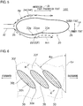
- Fig. 5 is a view schematically illustrating the airflow Af on the surface of the upper 20 when the wearer who wears the shoe 100 swings his/her leg in planar view.
- a difference in speed of the airflow Af occurs by an irregular surface when the airflow Af flows along the surface of the upper 20.
- a low pressure region Am in which a pressure is lowered in accordance with a difference in speed of the airflow Af and a high pressure region Ap in which the pressure increases occur on the surface of the upper 20.
- the low pressure region Am can occur posterior to a portion near a bulge portion corresponding to the ball of the foot on an inner foot outer surface 22f of the inner foot portion 22 of the upper 20.
- the high pressure region Ap can occur from a toe portion 26 toward an outer foot outer surface 24f of the outer foot portion 24 of the upper 20.
- Fig. 6 is a view schematically illustrating the air sucking out portion 30.
- Fig. 7 is a cross-sectional diagram of the air sucking out portion 30 cut along line A-A in Fig. 6 .
- a plurality of air sucking out portions 30 is provided on the inner foot outer surface 22f of the inner foot portion 22 of the upper 20.
- the air sucking out portion 30 has a ventilation structure which enables ventilation between the internal space 20a and outside air. Air Ag in the internal space 20a is sucked out to outside through the air sucking out portion 30 by a negative pressure occurring on the surface of the upper 20 when the wearer who wears the shoe 100 swings his/her leg (see Fig. 7 ).
- the air sucking out portions 30 extend while tilting by a predetermined first angle ⁇ p with respect to a vertical line Lv when the shoe 100 is placed in a horizontal state.
- the first angle ⁇ p will be described later.
- the air sucking out portion 30 of the present embodiment has a slit shape of a rectangle, an oval, or the like, which is elongated in an extending direction, that is, in a longitudinal direction in side view.
- a plurality of air sucking out portions 30 is arranged substantially parallel to each other.
- the slit shape of the air sucking out portion 30 is not limited to a rectangle and an oval and may be other shapes such as a meandering shape and a trapezoid shape.
- the air sucking out portion 30 may have a configuration where a plurality of punching holes is obliquely disposed. In these cases, it is only necessary that lines connecting centers of respective anterior edges and posterior edges tilt by the first angle ⁇ p.
- a ratio of the length in the longitudinal direction with respect to the length in a lateral direction is, for example, equal to or greater than 110%, preferably, equal to or greater than 150%, and, more preferably, equal to or greater than 200%.
- the air sucking out portion 30 dents from the inner foot outer surface 22f.
- the air sucking out portion 30 includes an opening 30h provided on the inner foot outer surface 22f, and a meshed body 30j provided on the internal space 20a side of the opening 30h.
- the air sucking out portion 30 may be a simple opening, and the meshed body 30j is provided at the opening 30h with the objective of reducing entrance of sands or pebbles and reinforcing the opening.
- the air sucking out portion 30 has a structure in which the meshed body 30j is laminated on the internal space 20a side of the inner foot outer surface 22f on which the opening 30h is provided.
- a difference in level between the inner foot outer surface 22f and the meshed body 30j preferably falls within a range between 0.1 mm and 20 mm with the objective of effectively sucking out air.
- the inner foot outer surface 22f on which the opening 30h is provided and the meshed body 30j may be separately formed and may be pasted by means of adhesion, or the like.
- the inner foot outer surface 22f on which the opening 30h is provided and the meshed body 30j are formed through weave which enables a thick region and a thin region to be integrally formed.
- the inner foot outer surface 22f on which the opening 30h is provided and the meshed body 30j may be integrally formed through jacquard weave or jacquard knitting.
- the air sucking out portion 30 in this example is a relief-shaped recessed portion which is formed through jacquard weave or jacquard knitting.
- an aperture ratio, mesh opening, a wire diameter, and the number of meshes of the meshed body 30j can be determined through experiments and simulation in accordance with desired air resistance and desired dust-proof performance.
- sufficient ventilation characteristics can be achieved by flat knitting, or the like, in which the meshed body 30j is knitted with knitting machine of 26 gauges using a string having a diameter of 80 deniers.
- a material knitted with a string having a diameter which is approximately twice the diameter of the meshed body 30j can be used as the inner foot outer surface 22f.
- the inner foot outer surface 22f only requires to have a ventilation rate of approximately 250 cm 3 /(cm 2 ⁇ s) in a Frazier type air permeability test specified in JISL1096, and the meshed body 30j preferably has a further higher ventilation rate.
- the specifications are not limited to those described above, and there may be visible differences between the meshed body 30j and the inner foot outer surface 22f in specifications such as an aperture ratio, mesh opening, a wire diameter and the number of meshes.
- the air sucking out portion 30 is preferably provided in a region where a negative pressure is likely to occur. As illustrated in Fig. 3 , it can be said that a region which cannot be viewed when viewed from a front in a direction along the width-direction center line La of the shoe 100 among the inner foot outer surface 22f is a region where the airflow Af is blocked by the toe portion 26, and thus, a negative pressure is likely to occur.
- the air sucking out portion 30 may therefore include a portion which is provided in a region which cannot be viewed when viewed from the front in the direction along the width-direction center line La of the shoe 100 among the inner foot outer surface 22f. In other words, the air sucking out portion 30 may include a portion which is provided in a region which cannot be viewed when viewed from the front of the shoe 100.
- the air sucking out portion 30 of the present embodiment therefore includes a portion which is provided in a longitudinal region located at equal to or greater than 30% and equal to or less than 80% from the toe portion 26.
- a negative pressure is likely to occur particularly in a longitudinal-direction range 22pe specified by an innermost point 22e located innermost and an outermost point 22p located outermost in planar view among the anterior foot portion 22a of the inner foot outer surface 22f (see Fig. 3 ).
- a negative pressure is likely to occur in a range 22pe from the innermost point 22e to the outermost point 22p.
- the air sucking out portion 30 of the present embodiment therefore includes a portion provided in the range 22pe.
- the airflow Af flows from an anterior upper portion to a posterior lower portion of the shoe 100 when the leg swings.
- the air sucking out portion 30 therefore tilts downward toward a posterior portion along a direction of the airflow Af so as to efficiently suck out air.
- the posterior edge 30e in the extending direction of the air sucking out portion 30 is positioned below the anterior edge 30f.
- the posterior edge 30e of the air sucking out portion 30 is positioned below a line Lc connecting the innermost point 22e and the outermost point 22p of the upper 20, and the anterior edge 30f of the air sucking out portion 30 is positioned above the line Lc.
- Fig. 8 is a bar graph indicating a result of study by the present inventors regarding relationship between an angle formed by the extending direction of the air sucking out portion 30 and the direction of the airflow Af, and ventilation characteristics of the air sucking out portion 30.
- the ventilation characteristics of the air sucking out portion 30 are defined as an amount of air ventilated per unit time when swing of the leg is simulated and the shoe 100 faces opposing wind from the front.
- Fig. 8 indicates the ventilation characteristics expressed with a relative ratio when a reference value set in advance is set as 100 on a vertical axis, and a greater numerical value indicates more favorable ventilation characteristics.
- Fig. 8 indicates the ventilation characteristics expressed with a relative ratio when a reference value set in advance is set as 100 on a vertical axis, and a greater numerical value indicates more favorable ventilation characteristics.
- X indicates a case where the extending direction of the air sucking out portion 30 is parallel to the direction of the airflow Af, in which case the ventilation efficiency is 82.
- Y indicates a case where the extending direction of the air sucking out portion 30 is orthogonal to the direction of the airflow Af, in which case the ventilation efficiency is 42.
- the ventilation characteristics in a case where the extending direction of the air sucking out portion 30 is parallel to the direction of the airflow Af are approximately twice as favorable as the ventilation characteristics in a case where the extending direction of the air sucking out portion 30 is orthogonal to the direction of the airflow Af. This may be because, in a case where the extending direction of the air sucking out portion 30 is orthogonal to the direction of the airflow Af, the airflow Af mainly collides with a long side of the opening 30h, at which a pressure locally increases and a sucking out effect decreases.
- the air sucking out portion 30 preferably extends in a direction substantially parallel to the direction of the airflow Af to improve ventilation characteristics.
- Fig. 9 and Fig. 10 are graphs indicating relationship between an angle ⁇ s of the shoe 100 with respect to a swing position of the leg and swing speed Vs of the shoe 100.
- Fig. 9 indicates a case of running at 17 km/h
- Fig. 10 indicates a case of running at 12 km/h.
- the angle ⁇ s of the shoe 100 is indicated as a positive numerical value in a case where the heel portion 28 rotates counterclockwise around the toe portion 26 in side view and indicated as a negative numerical value in a case where the heel portion 28 rotates clockwise assuming that the angle ⁇ s in a state where the shoe 100 is placed on a horizontal plane is 0° as illustrated in Fig. 4 .
- the swing speed Vs of the shoe 100 indicates speed in a direction of tangent of the shoe 100 which swings.
- Fig. 9 and Fig. 10 indicate a stroke position of the shoe 100 in a case where a stroke of one cycle of swing of the leg is set as 100% on a horizontal axis.
- Fig. 9 and Fig. 10 indicate the swing speed Vs of the shoe 100 corresponding to a left vertical axis with a dashed line and indicate the angle ⁇ s of the shoe 100 corresponding to a right vertical axis with a solid line.
- the swing speed Vs becomes equal to or higher than 95% (equal to or higher than 10 m/s) of peak speed in a range of the angle ⁇ s from 72° to 13°.
- the swing speed Vs in a case of running at 12 km/h, the swing speed Vs becomes equal to or higher than 95% (equal to or higher than 7.3 m/s) of the peak speed in a range of the angle ⁇ s from 70° to 12°.
- the swing speed Vs of equal to or higher than 95% of the peak speed can be obtained in a range of the angle ⁇ s of the shoe 100 from 70° to 20° in both running speed.
- the angle ⁇ s of the shoe 100 is 45° ⁇ 25° in a state where the swing speed Vs is close to the peak speed.
- a first angle ⁇ p of the extending direction of the air sucking out portion 30 with respect to a vertical line Lv will be described.
- the first angle ⁇ p is indicated with a positive numerical value in a case where the air sucking out portion 30 rotates counterclockwise so that the anterior edge 30f tilts forward in side view as illustrated in Fig. 6 , and is indicated with a negative numerical value in a case where the air sucking out portion 30 rotates clockwise so that the anterior edge 30f tilts backward, assuming that the first angle ⁇ p in a state where the anterior edge 30f is located immediately above the posterior edge 30e centering around the posterior edge 30e of the air sucking out portion 30 is set as 0°.
- the extending direction of the air sucking out portion 30 is preferably substantially parallel to the direction of the airflow Af.
- the first angle ⁇ p is set within a range from 20° to 70°, and the anterior edge 30f in the extending direction is located above the posterior edge 30e in a horizontal state.
- the extending direction of the air sucking out portion 30 becomes substantially parallel to the direction of the airflow Af in a state where the swing speed Vs is close to the peak speed, so that a negative pressure can be effectively utilized.
- Fig. 11 is a view schematically illustrating the air intake portion 40.
- Fig. 12 is a cross-sectional diagram of the air intake portion 40 cut along a line B-B in Fig. 11 .
- the air intake portion 40 functions as a ventilation portion for taking in outside air Aj into the internal space 20a.
- the air intake portion 40 is disposed in the high pressure region Ap in which a pressure increases in accordance with a difference in speed of the airflow Af when the wearer who wears the shoe 100 swings his/her leg, and has a configuration which enables air to be efficiently introduced with this pressure.
- the air intake portion 40 is provided on another outer surface except the inner foot outer surface 22f on the outer surface of the upper 20.
- the airflow Af hits a region which can be viewed from the front of the upper 20 when the leg swings, and thus, the air intake portion 40 may include a portion provided in a region which can be viewed from the front of the shoe 100.
- the air intake portion 40 includes a first air intake portion 40T provided on a toe outer surface 26f at the toe portion 26, and a second air intake portion 40S provided on an outer foot outer surface 24f of the outer foot portion 24.
- the toe outer surface 26f and the outer foot outer surface 24f will be collectively referred to as an intake portion outer surface.
- the air intake portion 40 of the present embodiment has a slit shape of a rectangle, an oval, or the like, which is elongated in the extending direction, that is, in the longitudinal direction in side view.
- a plurality of first air intake portions 40T is arranged in substantially parallel to each other on the toe outer surface 26f.
- a plurality of second air intake portions 40S is arranged in substantially parallel to each other on the outer foot outer surface 24f.
- the slit shape of the air intake portion 40 is not limited to a rectangle and an oval and may be other shapes such as a meandering shape and a trapezoid shape.
- the air sucking out portion 30 may have a configuration where a plurality of punching holes is obliquely disposed. In these cases, it is only necessary that lines connecting centers of respective anterior edges and posterior edges tilt by a predetermined angle.
- a ratio of the length in the longitudinal direction with respect to the length in a lateral direction is, for example, equal to or greater than 110%, preferably, equal to or greater than 150%, and, more preferably, equal to or greater than 200%.
- the air intake portion 40 has a ventilation structure which enables ventilation between the internal space 20a and outside air. As illustrated in Fig. 12 , the air intake portion 40 dents from an intake portion outer surface.
- the air intake portion 40 includes an opening 40h provided on the intake portion outer surface, and a meshed body 40j provided on the internal space 20a side of the opening 40h.
- the air intake portion 40 may be a simple opening, and the meshed body 40j is provided at the opening 40h with the objective of reducing entrance of sands or pebbles and reinforcing the opening.
- the air intake portion 40 has a structure in which the meshed body 40j is laminated on the internal space 20a side of the intake portion outer surface on which the opening 40h is provided.
- a difference in level between the outer foot outer surface 24f and the meshed body 40j preferably falls within a range between 0.1 mm and 20 mm with the objective of effectively intaking air.
- the intake portion outer surface on which the opening 40h is provided and the meshed body 40j may be separately formed and pasted by means of adhesion, or the like.
- the intake portion outer surface on which the opening 40h is provided and the meshed body 40j are integrally formed through jacquard weave or jacquard knitting.
- the air intake portion 40 is formed through jacquard weave or jacquard knitting.
- specifications such as an aperture ratio, mesh opening, a wire diameter, and the number of meshes of the meshed body 40j can be determined through experiments and simulation in accordance with desired air resistance and desired dust-proof performance.
- specifications such as an aperture ratio, mesh opening, a wire diameter, the number of meshes of the meshed body 40j may be made the same as those of the meshed body 30j.
- sufficient ventilation characteristics can be achieved by flat knitting, or the like, in which the meshed body 40j is knitted with knitting machine of 26 gauges using a string having a diameter of 80 deniers.
- a material knitted with a string having a diameter which is approximately twice the diameter of the meshed body 40j can be used as the outer foot outer surface 24f and the toe outer surface 26f.
- the outer foot outer surface 24f and the toe outer surface 26f only require to have a ventilation rate of approximately 250 cm 3 /(cm 2 ⁇ s) in a Frazier type air permeability test specified in JISL1096, and the meshed body 40j preferably has a further higher ventilation rate.
- the specifications are not limited to those described above, and there may be visible differences between the meshed body 40j, and the outer foot outer surface 24f and the toe outer surface 26f in specifications such as an aperture ratio, mesh opening, a wire diameter and the number of meshes.
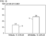
- Fig. 13 is a bar graph indicating a result of study by the present inventors regarding relationship between an angle formed by the extending direction of the air intake portion 40 and the direction of the airflow Af, and ventilation characteristics of the air intake portion 40.
- the ventilation characteristics of the air intake portion 40 are defined as an amount of air ventilated per unit time when swing of the leg is simulated and the shoe 100 faces opposing wind from the front.
- Fig. 13 indicates the ventilation characteristics expressed with a relative ratio when a reference value set in advance is set as 100 on a vertical axis, and a greater numerical value indicates more favorable ventilation characteristics.
- X indicates a case where the extending direction of the air intake portion 40 is parallel to the direction of the airflow Af, in which case the ventilation efficiency is 14.
- Y indicates a case where the extending direction of the air intake portion 40 is orthogonal to the direction of the airflow Af, in which case the ventilation efficiency is 28.
- Ventilation characteristics in a case where the extending direction of the air intake portion 40 is orthogonal to the direction of the airflow Af are approximately twice as favorable as the ventilation characteristics in a case where the extending direction of the air intake portion 40 is parallel to the direction of the airflow Af.
- the airflow Af mainly collides with a long side of the opening 40h, at which a pressure locally increases, and an intake effect is improved.
- the air intake portion 40 preferably extends in a direction substantially orthogonal to the direction of the airflow Af to improve ventilation characteristics.
- the extending direction of the first air intake portion 40T will be described.
- the first air intake portion 40T may extend in a width direction at the toe portion 26.
- the extending direction of the first air intake portion 40T is substantially orthogonal to the direction of the airflow Af, so that air can be efficiently taken in.
- the extending direction of the second air intake portion 40S will be described.
- the extending direction of the second air intake portion 40S is preferably substantially orthogonal to the direction of the airflow Af at an angle ⁇ s (45° ⁇ 25°) of the shoe 100 in a state where the swing speed Vs is close to peak speed.
- the second air intake portion 40S of the present embodiment therefore tilts so that an anterior edge 40f in the extending direction is located below a posterior edge 40e in a horizontal state. In other words, the second air intake portion 40S tilts downward toward an anterior portion so as to substantially orthogonal to the direction of the airflow Af.
- a tilt angle ⁇ q of the second air intake portion 40S with respect to the vertical line Lv may fall within a range from 20° to 70°.
- the extending direction of the second air intake portion 40S is substantially orthogonal to the direction of the airflow Af in a state where the swing speed Vs is close to the peak speed, so that air can be efficiently taken in.
- the air exhausting portion 44 will be described with reference to Fig. 1 and Fig. 2 . As illustrated in Fig. 1 and Fig. 2 , the air exhausting portion 44 of the present embodiment is provided at the heel portion 28 of the upper 20.
- the air exhausting portion 44 functions as a ventilation portion which is capable of exhausting air in the internal space 20a.
- the air exhausting portion 44 includes a first air exhausting portion 44P provided on a heel side of the inner foot outer surface 22f, and a second air exhausting portion 44S provided on a heel side of the outer foot outer surface 24f.
- the air exhausting portion 44 has a slit shape of a rectangle, an oval, or the like, which is elongated in the extending direction.
- the first air exhausting portion 44P tilts in the same direction as the tilt direction of the air sucking out portion 30, and the second air exhausting portion 44S tilts in the same direction as the tilt direction of the second air intake portion 40S.
- the air exhausting portion 44 dents from the outer surfaces 22f and 24f and includes an opening 44h and a meshed body 44j provided on the internal space 20a side.
- the opening 44h has characteristics similar to the characteristics of the opening 30h
- the meshed body 44j has characteristics similar to the characteristics of the meshed body 30j.
- specifications such as an aperture ratio, mesh opening, a wire diameter and the number of meshes of the meshed body 44j may be made the same as those of the meshed body 30j.
- part of the heel counter may be cut out and the air exhausting portion 44 may be disposed at the cutout portion.
- Fig. 14 is a developed view schematically illustrating a state where the upper 20 is developed on a plane.
- the first air intake portion 40T and the second air intake portion 40S may extend in the same direction as the extending direction of the air sucking out portion 30 in a state where the upper 20 is developed on a plane.
- the air exhausting portion 44 may extend in the same direction as the extending direction of the air sucking out portion 30 in a state where the upper 20 is developed on a plane.
- the air sucking out portion 30, the first air intake portion 40T, the second air intake portion 40S and the air exhausting portion 44 tilt in the same direction within a range from 20° to 70° with respect to the center line La.
- the air sucking out portion 30, the first air intake portion 40T, the second air intake portion 40S and the air exhausting portion 44 are integrally formed with the upper 20 through jacquard weave or jacquard knitting.
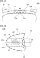
- Fig. 15 is a rear view illustrating a portion around the shoe tongue 70.
- a concave-convex portion 70p is provided on the internal space 20a side of the shoe tongue 70, and the concave-convex portion 70p is formed so as to enable ventilation in a thickness direction (vertical direction) of the shoe tongue 70.
- the shoe tongue 70 has a ventilation portion 70c which is formed with a material which enables ventilation in the thickness direction at a central portion of the width direction (horizontal direction in Fig. 15 ), and the concave-convex portion 70p is provided on a surface on the internal space 20a side of the ventilation portion 70c.
- the ventilation portion 70c may be formed with a porous material such as a foam resin.
- the concave-convex portion 70p forms concave-convex portion space 70a between the top of the foot 8 and the shoe tongue 70 and ventilates air in the concave-convex portion space 70a to outside via the concave-convex portion 70p.
- the shape of the concave-convex portion 70p can be determined through simulation or experiments in accordance with desired ventilation characteristics.
- the air intake hole 46 will be described with reference to Fig. 1 and Fig. 2 .
- the air intake hole 46 of the present embodiment is formed so as to penetrate part of an outsole 12 rolled up to the toe portion 26 of the upper 20 in a longitudinal direction.
- the air intake hole 46 functions as a ventilation portion which is capable of taking in air into the internal space 20a.
- the air intake hole 46 of the present embodiment has a substantially rectangular shape which is horizontally long in front view.
- a reinforcing rib 46b may be provided around the air intake hole 46.
- a lower edge of the air intake hole 46 of the present embodiment is disposed above an innersole or a shoe insole (upper surface inside the shoe). Providing the air intake hole 46 enables air to be taken in also from the front of the shoe 100, so that ventilation performance can be improved.
- the shoe 100 includes the upper 20 surrounding internal space 20a for accommodating a foot.
- the air sucking out portion 30 from which air is sucked out from the internal space 20a to outside when a leg swings is provided on the inner foot outer surface 22f of the inner foot portion 22 of the upper 20, and the air sucking out portion 30 extends in a direction which tilts by the predetermined first angle ⁇ p with respect to a vertical direction in a case where the shoe 100 is placed on a horizontal plane and dents from the inner foot outer surface 22f.
- a negative pressure is caused to occur at the air sucking out portion 30 by the outside airflow Af which flows along the inner foot outer surface 22f, so that air inside the internal space 20a can be sucked out to outside by utilizing this negative pressure. It is thereby possible to effectively ventilate inside the shoe 100. Further, the air sucking out portion 30 obliquely extends and dents, which increases a region along flow of outside air, and which makes it possible to effectively utilize a negative pressure.
- the air sucking out portion 30 may include a portion provided in a region which cannot be viewed from the front in a direction along the width-direction center line La of the shoe 100 among the inner foot outer surface 22f. In this case, a negative pressure is likely to occur in the region which cannot be viewed from the front of the inner foot outer surface 22f, so that it is possible to achieve efficient ventilation.
- the air sucking out portion 30 may include a portion provided in a longitudinal-direction region which is equal to or greater than 30% and equal to or less than 80% from the toe portion 26 among the inner foot outer surface 22f.
- a negative pressure is likely to occur in the longitudinal-direction region which is equal to or greater than 30% and equal to or less than 80% from the toe portion 26 of the inner foot outer surface 22f, so that it is possible to achieve efficient ventilation.
- the air sucking out portion 30 may include a portion provided in a longitudinal-direction range 22pe specified by an innermost point 22e located innermost and an outermost point 22p located outermost in planar view among the anterior foot portion 22a of the inner foot outer surface 22f.
- a negative pressure is likely to occur in the longitudinal-direction range 22pe of the anterior foot portion 22a of the inner foot outer surface 22f of the upper 20, so that it is possible to achieve efficient ventilation.
- a posterior edge 30e of the air sucking out portion 30 may located below a line Lc connecting the innermost point 22e and the outermost point 22p of the upper 20. In this case, a negative pressure is likely to occur in a lower portion from the line Lc of the upper 20, so that it is possible to achieve efficient ventilation.
- the first angle ⁇ p of the air sucking out portion 30 may fall within a range from 20° to 70°, and the air sucking out portion 30 may have a slit shape in which the posterior edge 30e tilts downward below the anterior edge 30f.
- the extending direction of the air sucking out portion 30 can be made substantially parallel to the direction of the outside airflow Af at a shoe angle at which the swing speed of the leg becomes peak speed upon running. It is thereby possible to effectively utilize a negative pressure.
- the air intake portion 40 for taking in outside air may be provided on another outer surfaces 24f and 26f except the inner foot outer surface 22f among the outer surface of the upper 20, and the air intake portion 40 may extend in a direction intersecting with the outside airflow Af when the leg swings, and may dent from the other outer surfaces 24f and 26f.
- the outside air is taken in through the air intake portion 40, so that it is possible to efficiently ventilate inside the shoe 100.
- the air intake portion 40 extends in a cross direction, so that it is possible to efficiently take in outside air.
- the air intake portion 40 dents, so that it is possible to easily take in air while causing air to be taken in to collide with this portion.
- the air intake portion 40 may include a portion provided in a region which can be viewed when viewed from the front in a direction along the width-direction center line La of the shoe 100. In this case, outside air hits the region which can be viewed from this direction when the leg swings, so that it is possible to efficiently take in outside air.
- the air intake portion 40 may extend in the same direction as the extending direction of the air sucking out portion 30 in a state where the upper 20 is developed on a plane. In this case, it is possible to make the shoe physically beautiful and facilitate manufacturing in a case where the air intake portion 40 is manufactured through weave or knitting.
- the air intake portion 40 may be provided at the toe portion 26 of the upper 20 and may extend in a width direction. In this case, it is possible to effectively take in fresh air into the internal space 20a.
- the air exhausting portion 44 which is capable of exhausting air in the internal space 20a may be provided at the heel portion 28 of the upper 20. In this case, it is possible to exhaust air also from a posterior portion.
- the shoe tongue 70 on which the concave-convex portion 70p is provided on the internal space 20a side may be provided, and the concave-convex portion 70p may be formed to enable ventilation in a thickness direction of the shoe tongue 70.
- the concave-convex portion 70p forms space between the top of the foot 8 and the shoe tongue 70, so that it is possible to achieve smooth ventilation through the concave-convex portion 70p.
- the air sucking out portion 30 may be formed through jacquard weave or jacquard knitting. In this case, it is possible to easily form the opening 30h and the meshed body 30j of the air sucking out portion 30.
- the concave-convex portion may be provided on the internal space 20a side of the toe portion 26.
- Fig. 16 is a plan view schematically illustrating the shoe 100 according to a first modified example.
- Fig. 16 illustrates a portion around the toe portion 26.
- a concave-convex portion 26p is provided on the internal space 20a side of the toe portion 26 in the present modified example.
- concave-convex portion space is formed between the concave-convex portion 26p and the foot, and ventilation in a planar direction is encouraged at the concave-convex portion 26p, so that it is possible to achieve efficient ventilation through the air intake portion 40.
- the concave-convex portion 26p may be provided anywhere in a range in which desired ventilation performance can be obtained.
- the concave-convex portion 26p is provided in a region put between two lines Lp which extend from right and left ends of the shoe tongue 70 to the toe in parallel to the center line La.
- the present invention is not limited to this.
- the inner foot outer surface on which the opening is provided may be formed with a material such as a resin, and the meshed body may be pasted on the inner foot outer surface.
- first air intake portion 40T and the second air intake portion 40S are provided, the present invention is not limited to this.
- at least one of the first air intake portion 40T or the second air intake portion 40S does not have to be provided.
- the shoe tongue 70 includes the ventilation portion 70c at the central portion in the width direction
- the present invention is not limited to this.
- the shoe tongue 70 may be formed with a material having ventilation characteristics in a thickness direction.
- the ventilation portion 70c may be provided at a portion other than the central portion.
- the ventilation portion 70c may be provided at a longitudinal-direction end portion or a width-direction end portion or may be provided in an entire area of the shoe tongue 70.
- a raised portion may be provided near a long side of an anterior portion of the opening 30h on the inner foot outer surface 22f. In this case, speed of the airflow Af becomes fast at the raised portion, so that a pressure of the opening 30h further decreases, and inside air is efficiently sucked out.
- the inner foot outer surface 22f may be constituted with a member different from the upper 20, and may have, for example, a configuration where the inner foot outer surface 22f rolls up and covers resin parts and the sole 10 which are separately formed. While a plurality of openings 30h is provided in Fig. 1 , only a single opening 30h may be provided.
- an area ratio of the opening 30h with respect to an inner foot side upper is, for example, equal to or greater than 1%, preferably, equal to or greater than 5%, and, more preferably, equal to or greater than 10% for an area which can be viewed when the present shoe is viewed from the inner foot side with the objective of achieving efficient ventilation.
- the area ratio may be equal to or greater than 1.5%, preferably, equal to or greater than 7.5%, and, more preferably, equal to or greater than 15% for an area of a region corresponding to the position L3 (position which is 80% from the toe portion 26) illustrated in Fig. 3 with the objective of achieving efficient ventilation.
- the area ratio of the opening 30h with respect to the inner foot side upper may be, for example, equal to or less than 40%, preferably, equal to or less than 20%, and, more preferably, equal to or less than 12% with the objective of maintaining strength and fit.
- the area ratio may be, for example, equal to or less than 50%, preferably, equal to or less than 25%, and, more preferably, equal to or less than 20% for the area corresponding to the position L3.
- a raised portion may be provided near a long side of a posterior portion of the opening 40h of the intake portion outer surface of the air intake portion 40. In this case, speed of the airflow Af becomes slow on a front side of the raised portion, so that a pressure of the opening 40h on the front side of the raised portion increases, and outside air can be efficiently taken in.
- outer foot outer surface 24f may be constituted with a member different from the upper 20, and may have, for example, a configuration where the outer foot outer surface 24f rolls up and covers resin parts and the sole 10 which are separately formed. While a plurality of openings 40h is provided in Fig. 2 , only a single opening 40h may be provided.
- an area ratio of the opening 40h with respect to an outer foot side upper is, for example, equal to or greater than 1%, preferably, equal to or greater than 5%, and, more preferably, equal to or greater than 10% for an area which can be viewed when the present shoe is viewed from the outer foot side with the objective of achieving efficient ventilation.
- the area ratio of the opening 40h with respect to the outer foot side upper may be, for example, equal to or less than 40%, preferably, equal to or less than 20%, and, more preferably, equal to or less than 12% with the objective of maintaining strength and fit.
- the present invention relates to shoes and can be utilized in shoes.
Landscapes
- Health & Medical Sciences (AREA)
- Epidemiology (AREA)
- General Health & Medical Sciences (AREA)
- Public Health (AREA)
- Footwear And Its Accessory, Manufacturing Method And Apparatuses (AREA)
Abstract
Description
- The present invention relates to shoes worn for sports, and the like.
- A shoe including ventilation means for reducing stuffiness inside the shoe in use is known. For example,
Patent Literature 1 discloses a shoe including ventilation means having a guide piece extending in an opening part. In this shoe, the guide piece is disposed to direct air toward inside of the opening part of the ventilation means during exercise using the shoe. This guide piece is disposed with a forward gradient with respect to a longitudinal axis of the shoe. This configuration makes the guide piece substantially parallel to flow of air when moving speed of the shoe becomes the highest, so that the air is easy to enter the ventilation means. - [Patent Literature 1]
JP 2004-174257 A - The present inventors have recognized the following with the objective of reducing stuffiness inside a shoe.
- When a wearer who wears shoes walks, runs or exercises, stuffiness inside the shoes due to moisture of sweat exhaled from the feet brings a feeling of discomfort to the wearer. The shoe disclosed in
Patent Literature 1 has a configuration where air is introduced inside the shoe with ventilation means including a guide piece. However, this shoe has room for improvement in exhaust of air inside the shoe. - The present inventors have recognized that there are points to be further improved particularly with the objective of effectively ventilating inside the shoe while a leg is swinging.
- The present invention has been made in view of such points, and an object of the present invention is to provide a shoe which is capable of effectively ventilating inside a shoe when a leg swings.
- In order to solve the above issues, a shoe according to an aspect of the present invention includes an upper surrounding internal space for accommodating a foot, and an air sucking out portion from which air is sucked out from the internal space to outside when a leg swings is provided on an inner foot outer surface of an inner foot portion of the upper, and the air sucking out portion extends in a direction which tilts by a predetermined first angle with respect to a vertical direction in a case where the shoe is placed on a horizontal plane and dents from the inner foot outer surface.
- Note that arbitrary combination of the above, a method, an apparatus, a program, a temporary or non-temporary storage medium in which the program is recorded, a system, and the like, among which components and expression of the present invention are mutually substituted are effective as an aspect of the present invention.
- According to the present invention, it is possible to provide a shoe which is capable of effectively ventilating inside the shoe when a leg swings.
-
-
Fig. 1 is a perspective view schematically illustrating a shoe in an embodiment according to the present invention. -
Fig. 2 is another perspective view schematically illustrating the shoe inFig. 1 . -
Fig. 3 is a plan view schematically illustrating the shoe inFig. 1 . -
Fig. 4 is a view schematically illustrating a state where a wearer who wears the shoes inFig. 1 is running. -
Fig. 5 is a view schematically illustrating flow of air when the wearer who wears the shoes inFig. 1 swings his/her leg. -
Fig. 6 is a view schematically illustrating an air sucking out portion of the shoe inFig. 1 . -
Fig. 7 is a cross-sectional diagram schematically illustrating the air sucking out portion of the shoe inFig. 1 . -
Fig. 8 is a graph indicating relationship between an angle of the air sucking out portion of the shoe inFig. 1 and ventilation characteristics. -
Fig. 9 is a graph indicating an angle with respect to a swing position of the shoe inFig. 1 and swing speed. -
Fig. 10 is another graph indicating the angle with respect to the swing position of the shoe inFig. 1 and the swing speed. -
Fig. 11 is a view schematically illustrating an air intake portion of the shoe inFig. 1 . -
Fig. 12 is a cross-sectional diagram schematically illustrating the air intake portion of the shoe inFig. 1 . -
Fig. 13 is a graph indicating relationship between an angle of the air intake portion of the shoe inFig. 1 and ventilation characteristics. -
Fig. 14 is a developed view schematically illustrating a state where an upper of the shoe inFig. 1 is developed on a plane. -
Fig. 15 is a rear view illustrating a portion around a shoe tongue of the shoe inFig. 1 . -
Fig. 16 is a plan view schematically illustrating a shoe according to a first modified example. - The present invention will be described below along with a preferred embodiment with reference to the drawings. In the embodiment and modified examples, the same reference numerals will be assigned to the same or equivalent components and members, and repetitive description will be omitted as appropriate. Further, sizes of members in the respective drawings are increased or reduced as appropriate to facilitate understanding. Still further, part of members which are not important in description of the embodiment is omitted in the respective drawings.
- Further, terms including ordinal numbers such as first and second, which are used to describe a variety of components, are used only for the purpose of distinguishing one component from other components and do not limit the components.
- A configuration of a
shoe 100 according to the embodiment of the present invention will be described below with reference to the drawings.Fig. 1 is a perspective view schematically illustrating theshoe 100 viewed from aninner foot portion 22. The following drawings includingFig. 1 illustrate a shoe for right foot unless otherwise described. The description in the present specification is similarly applied to a shoe for left foot.Fig. 2 is a side view schematically illustrating an air sucking out portion of theshoe 100.Fig. 2 is another perspective view schematically illustrating theshoe 100 viewed from an outer foot side.Fig. 3 is a view schematically illustrating theshoe 100 in planar view. - The
shoe 100 of the present embodiment can be used as sports shoes for, for example, walking and running. Theshoe 100 includes a sole 10 and an upper 20. The upper 20 surroundsinternal space 20a for accommodating a foot.Eyelets 72 through which a shoelace (not illustrated) is to pass are provided at the upper 20. Ashoe tongue 70 is provided on theinternal space 20a side of the upper 20. As illustrated inFig. 3 , an inner foot side (lower portion of the drawing) from a width-direction center line La of the upper 20 will be referred to as aninner foot portion 22, and an outer foot side (upper portion of the drawing) from the width-direction center line La will be referred to as anouter foot portion 24. Further, a direction toward theinner foot portion 22 from theouter foot portion 24 will be referred to as inward, and its opposite direction will be referred to as outward. - Further, a front side (left portion of the drawing) from a longitudinal-direction center line Lb will be referred to as an
anterior foot portion 22a of the upper 20, and a back side (right portion of the drawing) from the center line Lb will be referred to as aposterior foot portion 22b. Note that the center line La and the center line Lb may be orthogonal to each other. Further, an upper direction in a state where theshoe 100 is placed on a horizontal plane (hereinafter, referred to as a "horizontal state") will be referred to as above or upward, and its opposite direction will be referred to as below or downward. - The upper 20 includes an air sucking out
portion 30 for sucking out air from theinternal space 20a, anair intake portion 40 for taking in air into theinternal space 20a, an airexhausting portion 44 for exhausting air from theinternal space 20a, anair intake hole 46 for taking in air from the toe, and a shoe tongue concave-convex portion 70p which encourages ventilation through theshoe tongue 70. -
Fig. 4 is a view schematically illustrating a state where a wearer who wears theshoe 100 is running. As illustrated inFig. 4 , when the wearer walks or runs, the leg on which theshoe 100 is worn swings. When the leg swings, flow of air (hereinafter, referred to as "airflow Af") relative to a surface of the upper 20 occurs. -
Fig. 5 is a view schematically illustrating the airflow Af on the surface of the upper 20 when the wearer who wears theshoe 100 swings his/her leg in planar view. A difference in speed of the airflow Af occurs by an irregular surface when the airflow Af flows along the surface of the upper 20. A low pressure region Am in which a pressure is lowered in accordance with a difference in speed of the airflow Af and a high pressure region Ap in which the pressure increases occur on the surface of the upper 20. For example, the low pressure region Am can occur posterior to a portion near a bulge portion corresponding to the ball of the foot on an inner footouter surface 22f of theinner foot portion 22 of the upper 20. For example, the high pressure region Ap can occur from atoe portion 26 toward an outer footouter surface 24f of theouter foot portion 24 of the upper 20. - The air sucking out
portion 30 will be described.Fig. 6 is a view schematically illustrating the air sucking outportion 30.Fig. 7 is a cross-sectional diagram of the air sucking outportion 30 cut along line A-A inFig. 6 . In the present embodiment, a plurality of air sucking outportions 30 is provided on the inner footouter surface 22f of theinner foot portion 22 of the upper 20. The air sucking outportion 30 has a ventilation structure which enables ventilation between theinternal space 20a and outside air. Air Ag in theinternal space 20a is sucked out to outside through the air sucking outportion 30 by a negative pressure occurring on the surface of the upper 20 when the wearer who wears theshoe 100 swings his/her leg (seeFig. 7 ). - As illustrated in
Fig. 6 , the air sucking outportions 30 extend while tilting by a predetermined first angle θp with respect to a vertical line Lv when theshoe 100 is placed in a horizontal state. The first angle θp will be described later. The air sucking outportion 30 of the present embodiment has a slit shape of a rectangle, an oval, or the like, which is elongated in an extending direction, that is, in a longitudinal direction in side view. In the present embodiment, a plurality of air sucking outportions 30 is arranged substantially parallel to each other. The slit shape of the air sucking outportion 30 is not limited to a rectangle and an oval and may be other shapes such as a meandering shape and a trapezoid shape. For example, the air sucking outportion 30 may have a configuration where a plurality of punching holes is obliquely disposed. In these cases, it is only necessary that lines connecting centers of respective anterior edges and posterior edges tilt by the first angle θp. A ratio of the length in the longitudinal direction with respect to the length in a lateral direction is, for example, equal to or greater than 110%, preferably, equal to or greater than 150%, and, more preferably, equal to or greater than 200%. - As illustrated in
Fig. 7 , the air sucking outportion 30 dents from the inner footouter surface 22f. In the present embodiment, the air sucking outportion 30 includes anopening 30h provided on the inner footouter surface 22f, and ameshed body 30j provided on theinternal space 20a side of theopening 30h. The air sucking outportion 30 may be a simple opening, and themeshed body 30j is provided at theopening 30h with the objective of reducing entrance of sands or pebbles and reinforcing the opening. In this embodiment, the air sucking outportion 30 has a structure in which themeshed body 30j is laminated on theinternal space 20a side of the inner footouter surface 22f on which theopening 30h is provided. A difference in level between the inner footouter surface 22f and themeshed body 30j preferably falls within a range between 0.1 mm and 20 mm with the objective of effectively sucking out air. - The inner foot
outer surface 22f on which theopening 30h is provided and themeshed body 30j may be separately formed and may be pasted by means of adhesion, or the like. In the present embodiment, the inner footouter surface 22f on which theopening 30h is provided and themeshed body 30j are formed through weave which enables a thick region and a thin region to be integrally formed. For example, the inner footouter surface 22f on which theopening 30h is provided and themeshed body 30j may be integrally formed through jacquard weave or jacquard knitting. The air sucking outportion 30 in this example is a relief-shaped recessed portion which is formed through jacquard weave or jacquard knitting. - Specifications such as an aperture ratio, mesh opening, a wire diameter, and the number of meshes of the
meshed body 30j can be determined through experiments and simulation in accordance with desired air resistance and desired dust-proof performance. For example, in a case where the air sucking outportion 30 is formed through jacquard weave, sufficient ventilation characteristics can be achieved by flat knitting, or the like, in which themeshed body 30j is knitted with knitting machine of 26 gauges using a string having a diameter of 80 deniers. Meanwhile, a material knitted with a string having a diameter which is approximately twice the diameter of themeshed body 30j can be used as the inner footouter surface 22f. In this case, the inner footouter surface 22f only requires to have a ventilation rate of approximately 250 cm3/(cm2·s) in a Frazier type air permeability test specified in JISL1096, and themeshed body 30j preferably has a further higher ventilation rate. The specifications are not limited to those described above, and there may be visible differences between themeshed body 30j and the inner footouter surface 22f in specifications such as an aperture ratio, mesh opening, a wire diameter and the number of meshes. - The air sucking out
portion 30 is preferably provided in a region where a negative pressure is likely to occur. As illustrated inFig. 3 , it can be said that a region which cannot be viewed when viewed from a front in a direction along the width-direction center line La of theshoe 100 among the inner footouter surface 22f is a region where the airflow Af is blocked by thetoe portion 26, and thus, a negative pressure is likely to occur. The air sucking outportion 30 may therefore include a portion which is provided in a region which cannot be viewed when viewed from the front in the direction along the width-direction center line La of theshoe 100 among the inner footouter surface 22f. In other words, the air sucking outportion 30 may include a portion which is provided in a region which cannot be viewed when viewed from the front of theshoe 100. - As a result of study by the present inventors, it is indicated that when a length L1 from the
toe portion 26 to aheel portion 28 of the upper 20 is set as 100%, in air sucking outportion 30, a negative pressure is likely to occur in a longitudinal region L23 from a position L2 which is 30% from thetoe portion 26 to a position L3 which is 80% from thetoe portion 26 among theanterior foot portion 22a of the inner footouter surface 22f (seeFig. 3 ). The air sucking outportion 30 of the present embodiment therefore includes a portion which is provided in a longitudinal region located at equal to or greater than 30% and equal to or less than 80% from thetoe portion 26. - As a result of study by the present inventors, it is indicated that a negative pressure is likely to occur particularly in a longitudinal-direction range 22pe specified by an
innermost point 22e located innermost and anoutermost point 22p located outermost in planar view among theanterior foot portion 22a of the inner footouter surface 22f (seeFig. 3 ). In other words, a negative pressure is likely to occur in a range 22pe from theinnermost point 22e to theoutermost point 22p. The air sucking outportion 30 of the present embodiment therefore includes a portion provided in the range 22pe. - As illustrated in
Fig. 4 , the airflow Af flows from an anterior upper portion to a posterior lower portion of theshoe 100 when the leg swings. The air sucking outportion 30 therefore tilts downward toward a posterior portion along a direction of the airflow Af so as to efficiently suck out air. In other words, theposterior edge 30e in the extending direction of the air sucking outportion 30 is positioned below theanterior edge 30f. In this embodiment, as illustrated inFig. 1 , theposterior edge 30e of the air sucking outportion 30 is positioned below a line Lc connecting theinnermost point 22e and theoutermost point 22p of the upper 20, and theanterior edge 30f of the air sucking outportion 30 is positioned above the line Lc. -
Fig. 8 is a bar graph indicating a result of study by the present inventors regarding relationship between an angle formed by the extending direction of the air sucking outportion 30 and the direction of the airflow Af, and ventilation characteristics of the air sucking outportion 30. Note that the ventilation characteristics of the air sucking outportion 30 are defined as an amount of air ventilated per unit time when swing of the leg is simulated and theshoe 100 faces opposing wind from the front.Fig. 8 indicates the ventilation characteristics expressed with a relative ratio when a reference value set in advance is set as 100 on a vertical axis, and a greater numerical value indicates more favorable ventilation characteristics. InFig. 8 , X indicates a case where the extending direction of the air sucking outportion 30 is parallel to the direction of the airflow Af, in which case the ventilation efficiency is 82. Further, Y indicates a case where the extending direction of the air sucking outportion 30 is orthogonal to the direction of the airflow Af, in which case the ventilation efficiency is 42. - It has been found from the result that the ventilation characteristics in a case where the extending direction of the air sucking out
portion 30 is parallel to the direction of the airflow Af are approximately twice as favorable as the ventilation characteristics in a case where the extending direction of the air sucking outportion 30 is orthogonal to the direction of the airflow Af. This may be because, in a case where the extending direction of the air sucking outportion 30 is orthogonal to the direction of the airflow Af, the airflow Af mainly collides with a long side of theopening 30h, at which a pressure locally increases and a sucking out effect decreases. Alternatively, this may be because, in a case where the extending direction of the air sucking outportion 30 is orthogonal to the direction of the airflow Af, turbulence of the airflow Af becomes large at theopening 30h, and a sucking out effect decreases. From these, it can be said that the air sucking outportion 30 preferably extends in a direction substantially parallel to the direction of the airflow Af to improve ventilation characteristics. - The extending direction of the air sucking out
portion 30 becomes preferably parallel to the direction of the airflow Af when swing speed of the leg is high with the objective of improving ventilation characteristics.Fig. 9 and Fig. 10 are graphs indicating relationship between an angle θs of theshoe 100 with respect to a swing position of the leg and swing speed Vs of theshoe 100.Fig. 9 indicates a case of running at 17 km/h, andFig. 10 indicates a case of running at 12 km/h. - Note that the angle θs of the
shoe 100 is indicated as a positive numerical value in a case where theheel portion 28 rotates counterclockwise around thetoe portion 26 in side view and indicated as a negative numerical value in a case where theheel portion 28 rotates clockwise assuming that the angle θs in a state where theshoe 100 is placed on a horizontal plane is 0° as illustrated inFig. 4 . Further, the swing speed Vs of theshoe 100 indicates speed in a direction of tangent of theshoe 100 which swings. -
Fig. 9 and Fig. 10 indicate a stroke position of theshoe 100 in a case where a stroke of one cycle of swing of the leg is set as 100% on a horizontal axis.Fig. 9 and Fig. 10 indicate the swing speed Vs of theshoe 100 corresponding to a left vertical axis with a dashed line and indicate the angle θs of theshoe 100 corresponding to a right vertical axis with a solid line. - As a result of study, as illustrated in
Fig. 9 , in a case of running at 17 km/h, the swing speed Vs becomes equal to or higher than 95% (equal to or higher than 10 m/s) of peak speed in a range of the angle θs from 72° to 13°. Further, as illustrated inFig. 10 , in a case of running at 12 km/h, the swing speed Vs becomes equal to or higher than 95% (equal to or higher than 7.3 m/s) of the peak speed in a range of the angle θs from 70° to 12°. It can be said from this result that the swing speed Vs of equal to or higher than 95% of the peak speed can be obtained in a range of the angle θs of theshoe 100 from 70° to 20° in both running speed. In other words, it can be said that the angle θs of theshoe 100 is 45° ± 25° in a state where the swing speed Vs is close to the peak speed. - A first angle θp of the extending direction of the air sucking out
portion 30 with respect to a vertical line Lv will be described. Here, the first angle θp is indicated with a positive numerical value in a case where the air sucking outportion 30 rotates counterclockwise so that theanterior edge 30f tilts forward in side view as illustrated inFig. 6 , and is indicated with a negative numerical value in a case where the air sucking outportion 30 rotates clockwise so that theanterior edge 30f tilts backward, assuming that the first angle θp in a state where theanterior edge 30f is located immediately above theposterior edge 30e centering around theposterior edge 30e of the air sucking outportion 30 is set as 0°. - As described above, in a case where the angle θs of the
shoe 100 falls within a range from 70° to 20°, the extending direction of the air sucking outportion 30 is preferably substantially parallel to the direction of the airflow Af. To achieve this condition, in the present embodiment, the first angle θp is set within a range from 20° to 70°, and theanterior edge 30f in the extending direction is located above theposterior edge 30e in a horizontal state. In this case, the extending direction of the air sucking outportion 30 becomes substantially parallel to the direction of the airflow Af in a state where the swing speed Vs is close to the peak speed, so that a negative pressure can be effectively utilized. - The
air intake portion 40 will be described with reference toFig. 11 to Fig. 13 .Fig. 11 is a view schematically illustrating theair intake portion 40.Fig. 12 is a cross-sectional diagram of theair intake portion 40 cut along a line B-B inFig. 11 . As illustrated inFig. 12 , theair intake portion 40 functions as a ventilation portion for taking in outside air Aj into theinternal space 20a. Particularly, theair intake portion 40 is disposed in the high pressure region Ap in which a pressure increases in accordance with a difference in speed of the airflow Af when the wearer who wears theshoe 100 swings his/her leg, and has a configuration which enables air to be efficiently introduced with this pressure. - The
air intake portion 40 is provided on another outer surface except the inner footouter surface 22f on the outer surface of the upper 20. For example, the airflow Af hits a region which can be viewed from the front of the upper 20 when the leg swings, and thus, theair intake portion 40 may include a portion provided in a region which can be viewed from the front of theshoe 100. In the present embodiment, as illustrated inFig. 3 , theair intake portion 40 includes a firstair intake portion 40T provided on a toeouter surface 26f at thetoe portion 26, and a secondair intake portion 40S provided on an outer footouter surface 24f of theouter foot portion 24. That is because the high pressure region Ap is likely to occur from the toeouter surface 26f to the outer footouter surface 24f of theouter foot portion 24. The toeouter surface 26f and the outer footouter surface 24f will be collectively referred to as an intake portion outer surface. - The
air intake portion 40 of the present embodiment has a slit shape of a rectangle, an oval, or the like, which is elongated in the extending direction, that is, in the longitudinal direction in side view. As illustrated inFig. 3 , a plurality of firstair intake portions 40T is arranged in substantially parallel to each other on the toeouter surface 26f. Further, as illustrated inFig. 2 , a plurality of secondair intake portions 40S is arranged in substantially parallel to each other on the outer footouter surface 24f. The slit shape of theair intake portion 40 is not limited to a rectangle and an oval and may be other shapes such as a meandering shape and a trapezoid shape. For example, the air sucking outportion 30 may have a configuration where a plurality of punching holes is obliquely disposed. In these cases, it is only necessary that lines connecting centers of respective anterior edges and posterior edges tilt by a predetermined angle. A ratio of the length in the longitudinal direction with respect to the length in a lateral direction is, for example, equal to or greater than 110%, preferably, equal to or greater than 150%, and, more preferably, equal to or greater than 200%. - The
air intake portion 40 has a ventilation structure which enables ventilation between theinternal space 20a and outside air. As illustrated inFig. 12 , theair intake portion 40 dents from an intake portion outer surface. In the present embodiment, theair intake portion 40 includes anopening 40h provided on the intake portion outer surface, and ameshed body 40j provided on theinternal space 20a side of theopening 40h. Theair intake portion 40 may be a simple opening, and themeshed body 40j is provided at theopening 40h with the objective of reducing entrance of sands or pebbles and reinforcing the opening. In this embodiment, theair intake portion 40 has a structure in which themeshed body 40j is laminated on theinternal space 20a side of the intake portion outer surface on which theopening 40h is provided. A difference in level between the outer footouter surface 24f and themeshed body 40j preferably falls within a range between 0.1 mm and 20 mm with the objective of effectively intaking air. - The intake portion outer surface on which the
opening 40h is provided and themeshed body 40j may be separately formed and pasted by means of adhesion, or the like. In the present embodiment, the intake portion outer surface on which theopening 40h is provided and themeshed body 40j are integrally formed through jacquard weave or jacquard knitting. In other words, theair intake portion 40 is formed through jacquard weave or jacquard knitting. - Specifications such as an aperture ratio, mesh opening, a wire diameter, and the number of meshes of the
meshed body 40j can be determined through experiments and simulation in accordance with desired air resistance and desired dust-proof performance. With the objective of facilitating manufacturing, specifications such as an aperture ratio, mesh opening, a wire diameter, the number of meshes of themeshed body 40j may be made the same as those of themeshed body 30j. As described above, in a case where the air sucking outportion 30 is formed through jacquard weave, sufficient ventilation characteristics can be achieved by flat knitting, or the like, in which themeshed body 40j is knitted with knitting machine of 26 gauges using a string having a diameter of 80 deniers. Meanwhile, a material knitted with a string having a diameter which is approximately twice the diameter of themeshed body 40j can be used as the outer footouter surface 24f and the toeouter surface 26f. In this case, the outer footouter surface 24f and the toeouter surface 26f only require to have a ventilation rate of approximately 250 cm3/(cm2·s) in a Frazier type air permeability test specified in JISL1096, and themeshed body 40j preferably has a further higher ventilation rate. The specifications are not limited to those described above, and there may be visible differences between themeshed body 40j, and the outer footouter surface 24f and the toeouter surface 26f in specifications such as an aperture ratio, mesh opening, a wire diameter and the number of meshes. -
Fig. 13 is a bar graph indicating a result of study by the present inventors regarding relationship between an angle formed by the extending direction of theair intake portion 40 and the direction of the airflow Af, and ventilation characteristics of theair intake portion 40. Note that the ventilation characteristics of theair intake portion 40 are defined as an amount of air ventilated per unit time when swing of the leg is simulated and theshoe 100 faces opposing wind from the front.Fig. 13 indicates the ventilation characteristics expressed with a relative ratio when a reference value set in advance is set as 100 on a vertical axis, and a greater numerical value indicates more favorable ventilation characteristics. InFig. 13 , X indicates a case where the extending direction of theair intake portion 40 is parallel to the direction of the airflow Af, in which case the ventilation efficiency is 14. Further, Y indicates a case where the extending direction of theair intake portion 40 is orthogonal to the direction of the airflow Af, in which case the ventilation efficiency is 28. - It has been found from the result that ventilation characteristics in a case where the extending direction of the
air intake portion 40 is orthogonal to the direction of the airflow Af are approximately twice as favorable as the ventilation characteristics in a case where the extending direction of theair intake portion 40 is parallel to the direction of the airflow Af. This may be because, in a case where the extending direction of theair intake portion 40 is orthogonal to the direction of the airflow Af, the airflow Af mainly collides with a long side of theopening 40h, at which a pressure locally increases, and an intake effect is improved. From these, theair intake portion 40 preferably extends in a direction substantially orthogonal to the direction of the airflow Af to improve ventilation characteristics. - The extending direction of the first
air intake portion 40T will be described. With the objective of improving ventilation characteristics, the firstair intake portion 40T may extend in a width direction at thetoe portion 26. In this case, the extending direction of the firstair intake portion 40T is substantially orthogonal to the direction of the airflow Af, so that air can be efficiently taken in. - The extending direction of the second
air intake portion 40S will be described. With the objective of improving ventilation characteristics, the extending direction of the secondair intake portion 40S is preferably substantially orthogonal to the direction of the airflow Af at an angle θs (45° ± 25°) of theshoe 100 in a state where the swing speed Vs is close to peak speed. The secondair intake portion 40S of the present embodiment therefore tilts so that ananterior edge 40f in the extending direction is located below aposterior edge 40e in a horizontal state. In other words, the secondair intake portion 40S tilts downward toward an anterior portion so as to substantially orthogonal to the direction of the airflow Af. A tilt angle θq of the secondair intake portion 40S with respect to the vertical line Lv may fall within a range from 20° to 70°. In this case, the extending direction of the secondair intake portion 40S is substantially orthogonal to the direction of the airflow Af in a state where the swing speed Vs is close to the peak speed, so that air can be efficiently taken in. - The
air exhausting portion 44 will be described with reference toFig. 1 and Fig. 2 . As illustrated inFig. 1 and Fig. 2 , theair exhausting portion 44 of the present embodiment is provided at theheel portion 28 of the upper 20. - The
air exhausting portion 44 functions as a ventilation portion which is capable of exhausting air in theinternal space 20a. Theair exhausting portion 44 includes a firstair exhausting portion 44P provided on a heel side of the inner footouter surface 22f, and a secondair exhausting portion 44S provided on a heel side of the outer footouter surface 24f. Theair exhausting portion 44 has a slit shape of a rectangle, an oval, or the like, which is elongated in the extending direction. The firstair exhausting portion 44P tilts in the same direction as the tilt direction of the air sucking outportion 30, and the secondair exhausting portion 44S tilts in the same direction as the tilt direction of the secondair intake portion 40S. - The
air exhausting portion 44 dents from theouter surfaces opening 44h and ameshed body 44j provided on theinternal space 20a side. Theopening 44h has characteristics similar to the characteristics of theopening 30h, and themeshed body 44j has characteristics similar to the characteristics of themeshed body 30j. With the objective of facilitating manufacturing, specifications such as an aperture ratio, mesh opening, a wire diameter and the number of meshes of themeshed body 44j may be made the same as those of themeshed body 30j. Further, in a case where a heel counter is provided at theheel portion 28, part of the heel counter may be cut out and theair exhausting portion 44 may be disposed at the cutout portion. -
Fig. 14 is a developed view schematically illustrating a state where the upper 20 is developed on a plane. With the objective of facilitating manufacturing, the firstair intake portion 40T and the secondair intake portion 40S may extend in the same direction as the extending direction of the air sucking outportion 30 in a state where the upper 20 is developed on a plane. Further, theair exhausting portion 44 may extend in the same direction as the extending direction of the air sucking outportion 30 in a state where the upper 20 is developed on a plane. In the present embodiment, the air sucking outportion 30, the firstair intake portion 40T, the secondair intake portion 40S and theair exhausting portion 44 tilt in the same direction within a range from 20° to 70° with respect to the center line La. The air sucking outportion 30, the firstair intake portion 40T, the secondair intake portion 40S and theair exhausting portion 44 are integrally formed with the upper 20 through jacquard weave or jacquard knitting. - The shoe tongue concave-
convex portion 70p will be described with reference toFig. 15. Fig. 15 is a rear view illustrating a portion around theshoe tongue 70. In a case where the shoe tongue tightly adheres to the top of thefoot 8, this portion is likely to get stuffy. Thus, in the present embodiment, a concave-convex portion 70p is provided on theinternal space 20a side of theshoe tongue 70, and the concave-convex portion 70p is formed so as to enable ventilation in a thickness direction (vertical direction) of theshoe tongue 70. In other words, theshoe tongue 70 has aventilation portion 70c which is formed with a material which enables ventilation in the thickness direction at a central portion of the width direction (horizontal direction inFig. 15 ), and the concave-convex portion 70p is provided on a surface on theinternal space 20a side of theventilation portion 70c. Theventilation portion 70c may be formed with a porous material such as a foam resin. - The concave-
convex portion 70p forms concave-convex portion space 70a between the top of thefoot 8 and theshoe tongue 70 and ventilates air in the concave-convex portion space 70a to outside via the concave-convex portion 70p. The shape of the concave-convex portion 70p can be determined through simulation or experiments in accordance with desired ventilation characteristics. - The
air intake hole 46 will be described with reference toFig. 1 and Fig. 2 . As illustrated inFig. 1 and Fig. 2 , theair intake hole 46 of the present embodiment is formed so as to penetrate part of anoutsole 12 rolled up to thetoe portion 26 of the upper 20 in a longitudinal direction. Theair intake hole 46 functions as a ventilation portion which is capable of taking in air into theinternal space 20a. Theair intake hole 46 of the present embodiment has a substantially rectangular shape which is horizontally long in front view. A reinforcingrib 46b may be provided around theair intake hole 46. A lower edge of theair intake hole 46 of the present embodiment is disposed above an innersole or a shoe insole (upper surface inside the shoe). Providing theair intake hole 46 enables air to be taken in also from the front of theshoe 100, so that ventilation performance can be improved. - An overview of one aspect of the present invention is explained. The
shoe 100 according to an aspect of the present invention includes the upper 20 surroundinginternal space 20a for accommodating a foot. The air sucking outportion 30 from which air is sucked out from theinternal space 20a to outside when a leg swings is provided on the inner footouter surface 22f of theinner foot portion 22 of the upper 20, and the air sucking outportion 30 extends in a direction which tilts by the predetermined first angle θp with respect to a vertical direction in a case where theshoe 100 is placed on a horizontal plane and dents from the inner footouter surface 22f. - According to this aspect, when the wearer swings his/her leg by walking or running, a negative pressure is caused to occur at the air sucking out
portion 30 by the outside airflow Af which flows along the inner footouter surface 22f, so that air inside theinternal space 20a can be sucked out to outside by utilizing this negative pressure. It is thereby possible to effectively ventilate inside theshoe 100. Further, the air sucking outportion 30 obliquely extends and dents, which increases a region along flow of outside air, and which makes it possible to effectively utilize a negative pressure. - The air sucking out
portion 30 may include a portion provided in a region which cannot be viewed from the front in a direction along the width-direction center line La of theshoe 100 among the inner footouter surface 22f. In this case, a negative pressure is likely to occur in the region which cannot be viewed from the front of the inner footouter surface 22f, so that it is possible to achieve efficient ventilation. - In a case where a length from the
toe portion 26 to theheel portion 28 of the upper 20 is set as 100%, the air sucking outportion 30 may include a portion provided in a longitudinal-direction region which is equal to or greater than 30% and equal to or less than 80% from thetoe portion 26 among the inner footouter surface 22f. In this case, a negative pressure is likely to occur in the longitudinal-direction region which is equal to or greater than 30% and equal to or less than 80% from thetoe portion 26 of the inner footouter surface 22f, so that it is possible to achieve efficient ventilation. - The air sucking out
portion 30 may include a portion provided in a longitudinal-direction range 22pe specified by aninnermost point 22e located innermost and anoutermost point 22p located outermost in planar view among theanterior foot portion 22a of the inner footouter surface 22f. In this case, a negative pressure is likely to occur in the longitudinal-direction range 22pe of theanterior foot portion 22a of the inner footouter surface 22f of the upper 20, so that it is possible to achieve efficient ventilation. - A
posterior edge 30e of the air sucking outportion 30 may located below a line Lc connecting theinnermost point 22e and theoutermost point 22p of the upper 20. In this case, a negative pressure is likely to occur in a lower portion from the line Lc of the upper 20, so that it is possible to achieve efficient ventilation. - The first angle θp of the air sucking out
portion 30 may fall within a range from 20° to 70°, and the air sucking outportion 30 may have a slit shape in which theposterior edge 30e tilts downward below theanterior edge 30f. In this case, the extending direction of the air sucking outportion 30 can be made substantially parallel to the direction of the outside airflow Af at a shoe angle at which the swing speed of the leg becomes peak speed upon running. It is thereby possible to effectively utilize a negative pressure. - The
air intake portion 40 for taking in outside air may be provided on anotherouter surfaces outer surface 22f among the outer surface of the upper 20, and theair intake portion 40 may extend in a direction intersecting with the outside airflow Af when the leg swings, and may dent from the otherouter surfaces air intake portion 40, so that it is possible to efficiently ventilate inside theshoe 100. Further, theair intake portion 40 extends in a cross direction, so that it is possible to efficiently take in outside air. Still further, theair intake portion 40 dents, so that it is possible to easily take in air while causing air to be taken in to collide with this portion. - The
air intake portion 40 may include a portion provided in a region which can be viewed when viewed from the front in a direction along the width-direction center line La of theshoe 100. In this case, outside air hits the region which can be viewed from this direction when the leg swings, so that it is possible to efficiently take in outside air. - The
air intake portion 40 may extend in the same direction as the extending direction of the air sucking outportion 30 in a state where the upper 20 is developed on a plane. In this case, it is possible to make the shoe physically beautiful and facilitate manufacturing in a case where theair intake portion 40 is manufactured through weave or knitting. - The
air intake portion 40 may be provided at thetoe portion 26 of the upper 20 and may extend in a width direction. In this case, it is possible to effectively take in fresh air into theinternal space 20a. - The
air exhausting portion 44 which is capable of exhausting air in theinternal space 20a may be provided at theheel portion 28 of the upper 20. In this case, it is possible to exhaust air also from a posterior portion. - The
shoe tongue 70 on which the concave-convex portion 70p is provided on theinternal space 20a side may be provided, and the concave-convex portion 70p may be formed to enable ventilation in a thickness direction of theshoe tongue 70. In this case, the concave-convex portion 70p forms space between the top of thefoot 8 and theshoe tongue 70, so that it is possible to achieve smooth ventilation through the concave-convex portion 70p. - The air sucking out
portion 30 may be formed through jacquard weave or jacquard knitting. In this case, it is possible to easily form theopening 30h and themeshed body 30j of the air sucking outportion 30. - The example of the embodiment of the present invention has been described in detail above. The above-described embodiment merely describes a specific example for implementing the present invention. Content of the embodiment does not limit a technical scope of the present invention, and a number of design changes such as change, addition and deletion of components are possible within a range not deviating from idea of the invention recited in the claims. While description has been provided in the above-described embodiment regarding content to which such design changes are possible with notation of "of the embodiment", "in the embodiment", and the like, design changes are also possible to content without such notation. Further, hatched portions of cross-sections in the drawings do not limit a material of the hatched portions.
- Modified examples will be described below. In drawings and description of the modified examples, the same reference numerals will be assigned to components and members which are the same as or equivalent to those in the embodiment. Repetitive description with the embodiment will be omitted as appropriate, and description will be provided with emphasis on a configuration different from that in the embodiment.
- While the example has been described in the description of the embodiment where the concave-convex portion is provided at the
shoe tongue 70, the present invention is not limited to this. The concave-convex portion may be provided on theinternal space 20a side of thetoe portion 26. -
Fig. 16 is a plan view schematically illustrating theshoe 100 according to a first modified example.Fig. 16 illustrates a portion around thetoe portion 26. A concave-convex portion 26p is provided on theinternal space 20a side of thetoe portion 26 in the present modified example. In this case, concave-convex portion space is formed between the concave-convex portion 26p and the foot, and ventilation in a planar direction is encouraged at the concave-convex portion 26p, so that it is possible to achieve efficient ventilation through theair intake portion 40. - The concave-
convex portion 26p may be provided anywhere in a range in which desired ventilation performance can be obtained. In the present modified example, the concave-convex portion 26p is provided in a region put between two lines Lp which extend from right and left ends of theshoe tongue 70 to the toe in parallel to the center line La. - While the example has been described in the description of the embodiment where the inner foot
outer surface 22f on which theopening 30h is provided and themeshed body 30j are integrally formed through jacquard weave or jacquard knitting, the present invention is not limited to this. For example, the inner foot outer surface on which the opening is provided may be formed with a material such as a resin, and the meshed body may be pasted on the inner foot outer surface. - While the example has been described in the description of the embodiment where the first
air intake portion 40T and the secondair intake portion 40S are provided, the present invention is not limited to this. For example, at least one of the firstair intake portion 40T or the secondair intake portion 40S does not have to be provided. Further, it is not essential to provide theair exhausting portion 44. Still further, it is not essential to provide the shoe tongue concave-convex portion 70p and theair intake hole 46. - While the example has been described in the description of the embodiment where the
shoe tongue 70 includes theventilation portion 70c at the central portion in the width direction, the present invention is not limited to this. For example, theshoe tongue 70 may be formed with a material having ventilation characteristics in a thickness direction. Further, theventilation portion 70c may be provided at a portion other than the central portion. For example, theventilation portion 70c may be provided at a longitudinal-direction end portion or a width-direction end portion or may be provided in an entire area of theshoe tongue 70. - While the example has been described in the description of the embodiment where a portion around the
opening 30h of the inner footouter surface 22f is flat, the present invention is not limited to this. For example, a raised portion may be provided near a long side of an anterior portion of theopening 30h on the inner footouter surface 22f. In this case, speed of the airflow Af becomes fast at the raised portion, so that a pressure of theopening 30h further decreases, and inside air is efficiently sucked out. - Further, the inner foot
outer surface 22f may be constituted with a member different from the upper 20, and may have, for example, a configuration where the inner footouter surface 22f rolls up and covers resin parts and the sole 10 which are separately formed. While a plurality ofopenings 30h is provided inFig. 1 , only asingle opening 30h may be provided. - Further, an area ratio of the
opening 30h with respect to an inner foot side upper is, for example, equal to or greater than 1%, preferably, equal to or greater than 5%, and, more preferably, equal to or greater than 10% for an area which can be viewed when the present shoe is viewed from the inner foot side with the objective of achieving efficient ventilation. Further, the area ratio may be equal to or greater than 1.5%, preferably, equal to or greater than 7.5%, and, more preferably, equal to or greater than 15% for an area of a region corresponding to the position L3 (position which is 80% from the toe portion 26) illustrated inFig. 3 with the objective of achieving efficient ventilation. Meanwhile, in a case where the upper 20 is formed through jacquard weave or jacquard knitting, the area ratio of theopening 30h with respect to the inner foot side upper may be, for example, equal to or less than 40%, preferably, equal to or less than 20%, and, more preferably, equal to or less than 12% with the objective of maintaining strength and fit. In a similar manner, the area ratio may be, for example, equal to or less than 50%, preferably, equal to or less than 25%, and, more preferably, equal to or less than 20% for the area corresponding to the position L3. - While the example has been described in the description of the embodiment where the outer foot
outer surface 24f and a portion around theopening 40h of the toeouter surface 26f are flat, the present invention is not limited to this. For example, a raised portion may be provided near a long side of a posterior portion of theopening 40h of the intake portion outer surface of theair intake portion 40. In this case, speed of the airflow Af becomes slow on a front side of the raised portion, so that a pressure of theopening 40h on the front side of the raised portion increases, and outside air can be efficiently taken in. - Further, the outer foot
outer surface 24f may be constituted with a member different from the upper 20, and may have, for example, a configuration where the outer footouter surface 24f rolls up and covers resin parts and the sole 10 which are separately formed. While a plurality ofopenings 40h is provided inFig. 2 , only asingle opening 40h may be provided. - Further, an area ratio of the
opening 40h with respect to an outer foot side upper is, for example, equal to or greater than 1%, preferably, equal to or greater than 5%, and, more preferably, equal to or greater than 10% for an area which can be viewed when the present shoe is viewed from the outer foot side with the objective of achieving efficient ventilation. Meanwhile, in a case where the upper 20 is formed through jacquard weave or jacquard knitting, the area ratio of theopening 40h with respect to the outer foot side upper may be, for example, equal to or less than 40%, preferably, equal to or less than 20%, and, more preferably, equal to or less than 12% with the objective of maintaining strength and fit. - The above-described respective modified examples provide operation and effects similar to those in the above-described embodiment.
- Arbitrary combination of the above-described embodiment and the modified examples is also useful as an embodiment of the present invention. A new embodiment created by combination provides respective effects of the embodiment and the modified examples which are combined.
- The present invention relates to shoes and can be utilized in shoes.
- 20 upper, 20a internal space, 22 inner foot portion, 22a anterior foot portion, 22e innermost point, 22f inner foot outer surface, 22p outermost point, 22pe longitudinal-direction range, 24 outer foot portion, 24f outer foot outer surface, 26 toe portion, 28 heel portion, 30 air sucking out portion, 30e posterior edge, 30f anterior edge, 40 air intake portion, 40e posterior edge, 40f anterior edge, 44 air exhausting portion, 70 shoe tongue, 70a concave-convex portion space, 70p concave-convex portion, 100 shoe, L23 longitudinal region
Claims (13)
- A shoe comprising:an upper surrounding internal space for accommodating a foot,wherein an air sucking out portion from which air is sucked out from the internal space to outside when a leg swings is provided on an inner foot outer surface of an inner foot portion of the upper, andthe air sucking out portion extends in a direction which tilts by a predetermined first angle with respect to a vertical direction in a case where the shoe is placed on a horizontal plane and dents from the inner foot outer surface.
- The shoe according to claim 1, wherein the air sucking out portion includes a portion provided in a region which is not visible when viewed from a front in a direction along a width-direction center line of the shoe among the inner foot outer surface.
- The shoe according to claim 1 or 2, wherein in a case where a length from a toe portion to a heel portion of the upper is set as 100%, the air sucking out portion includes a portion provided in a longitudinal-direction region which is equal to or greater than 30% and equal to or less than 80% from the toe portion among the inner foot outer surface.
- The shoe according to any one of claims 1 to 3,
wherein the air sucking out portion includes a portion provided in a longitudinal-direction range specified by an innermost point located innermost and an outermost point located outermost in planar view among an anterior foot portion on the inner foot outer surface. - The shoe according to claim 4, wherein a posterior edge of the air sucking out portion is located below a line connecting the innermost point and the outermost point of the upper.
- The shoe according to any one of claims 1 to 5,
wherein the first angle of the air sucking out portion falls within a range from 20° to 70°, and a posterior edge of the air sucking out portion has a slit shape which tilts downward below an anterior edge of the air sucking out portion. - The shoe according to any one of claims 1 to 6,
wherein an air intake portion for taking in outside air is provided on another outer surface except the inner foot outer surface among an outer surface of the upper, and the air intake portion extends in a direction intersecting with outside airflow when the leg swings and dents from the other outer surface. - The shoe according to claim 7, wherein the air intake portion includes a portion provided in a region which is visible when viewed from a front in a direction along a width-direction center line of the shoe.
- The shoe according to claim 7 or 8, wherein the air intake portion extends in a same direction as an extending direction of the air sucking out portion in a state where the upper is developed on a plane.
- The shoe according to any one of claims 7 to 9,
wherein the air intake portion is provided at a toe portion of the upper and extends in a width direction. - The shoe according to any one of claims 1 to 10,
wherein an air exhausting portion which is capable of exhausting air in the internal space is provided at a heel portion of the upper. - The shoe according to any one of claims 1 to 11,
wherein a shoe tongue on which a concave-convex portion is provided on the internal space side is provided, and the concave-convex portion is formed to enable ventilation in a thickness direction of the shoe tongue. - The shoe according to any one of claims 1 to 12, wherein the air sucking out portion is formed through jacquard weave or jacquard knitting.
Applications Claiming Priority (1)
| Application Number | Priority Date | Filing Date | Title |
|---|---|---|---|
| PCT/JP2019/007802 WO2020174654A1 (en) | 2019-02-28 | 2019-02-28 | Shoe |
Publications (3)
| Publication Number | Publication Date |
|---|---|
| EP3932241A1 true EP3932241A1 (en) | 2022-01-05 |
| EP3932241A4 EP3932241A4 (en) | 2022-09-14 |
| EP3932241B1 EP3932241B1 (en) | 2024-09-18 |
Family
ID=72238891
Family Applications (1)
| Application Number | Title | Priority Date | Filing Date |
|---|---|---|---|
| EP19917084.6A Active EP3932241B1 (en) | 2019-02-28 | 2019-02-28 | Shoe |
Country Status (6)
| Country | Link |
|---|---|
| US (1) | US12514328B2 (en) |
| EP (1) | EP3932241B1 (en) |
| JP (1) | JP7288039B2 (en) |
| CN (1) | CN112261885B (en) |
| AU (1) | AU2019431997A1 (en) |
| WO (1) | WO2020174654A1 (en) |
Families Citing this family (1)
| Publication number | Priority date | Publication date | Assignee | Title |
|---|---|---|---|---|
| EP4520215A4 (en) * | 2022-06-10 | 2025-07-02 | Asics Corp | SHOE |
Family Cites Families (19)
| Publication number | Priority date | Publication date | Assignee | Title |
|---|---|---|---|---|
| US1763605A (en) * | 1929-11-09 | 1930-06-10 | David I Haskell | Shoe |
| US2188168A (en) * | 1938-09-03 | 1940-01-23 | Winkel Mabel | Shoe |
| JPS5447546U (en) | 1977-09-02 | 1979-04-02 | ||
| JPS60180511U (en) * | 1984-05-11 | 1985-11-30 | アキレス株式会社 | shoes |
| JPH0711901A (en) | 1993-06-29 | 1995-01-13 | Ishikawajima Harima Heavy Ind Co Ltd | Stripping control wing |
| JPH0711901U (en) * | 1993-08-04 | 1995-02-28 | ミドリ安全工業株式会社 | Breathable shoes |
| US6401364B1 (en) | 2000-06-15 | 2002-06-11 | Salomon S.A. | Ventilated shoe |
| DE10255094B4 (en) * | 2002-11-26 | 2017-03-09 | Adidas International Marketing B.V. | shoe |
| JP4505212B2 (en) * | 2003-01-10 | 2010-07-21 | 美津濃株式会社 | Shoes and double raschel warp knitted fabric used therefor |
| FR2856250B1 (en) * | 2003-06-17 | 2005-08-05 | Technisynthese Sarl | FOOTWEAR ARTICLE OF A NEW TYPE |
| US8146266B2 (en) * | 2005-06-02 | 2012-04-03 | The Timberland Company | Chimney structures for footwear and foot coverings |
| US8065818B2 (en) * | 2005-06-20 | 2011-11-29 | Nike, Inc. | Article of footwear having an upper with a matrix layer |
| US20070151121A1 (en) * | 2005-12-30 | 2007-07-05 | Touzov Igor V | Stretchable and transformable planar heat pipe for apparel and footwear, and production method thereof |
| JP5996915B2 (en) | 2012-04-16 | 2016-09-21 | 帝人フロンティア株式会社 | Shoes and shoes |
| CN203121178U (en) * | 2013-03-25 | 2013-08-14 | 温岭市城北鞋类检测有限公司 | Breathable casual shoes |
| US9867417B2 (en) * | 2013-07-11 | 2018-01-16 | Nike, Inc. | Article with tensioning system including tension balancing member |
| JP6346874B2 (en) | 2015-06-22 | 2018-06-20 | 株式会社竹虎 | shoes |
| CN205409941U (en) * | 2016-03-02 | 2016-08-03 | 特步(中国)有限公司 | Shoes with honeycomb formula vamp |
| JP2019005387A (en) * | 2017-06-27 | 2019-01-17 | 美津濃株式会社 | Sport shoes |
-
2019
- 2019-02-28 WO PCT/JP2019/007802 patent/WO2020174654A1/en not_active Ceased
- 2019-02-28 JP JP2021501490A patent/JP7288039B2/en active Active
- 2019-02-28 CN CN201980039288.4A patent/CN112261885B/en active Active
- 2019-02-28 US US17/254,062 patent/US12514328B2/en active Active
- 2019-02-28 EP EP19917084.6A patent/EP3932241B1/en active Active
- 2019-02-28 AU AU2019431997A patent/AU2019431997A1/en not_active Abandoned
Also Published As
| Publication number | Publication date |
|---|---|
| AU2019431997A1 (en) | 2021-01-21 |
| CN112261885B (en) | 2023-07-11 |
| EP3932241A4 (en) | 2022-09-14 |
| EP3932241B1 (en) | 2024-09-18 |
| JP7288039B2 (en) | 2023-06-06 |
| US20210259355A1 (en) | 2021-08-26 |
| WO2020174654A1 (en) | 2020-09-03 |
| US12514328B2 (en) | 2026-01-06 |
| JPWO2020174654A1 (en) | 2021-12-23 |
| CN112261885A (en) | 2021-01-22 |
Similar Documents
| Publication | Publication Date | Title |
|---|---|---|
| US11672304B2 (en) | Shoe sole, and shoe including shoe sole | |
| JP2004174257A (en) | shoes | |
| EP3932241B1 (en) | Shoe | |
| WO2023246405A1 (en) | Viewable air exhaust shoe sole | |
| US2480035A (en) | Ventilated boot | |
| CN220423263U (en) | Internally-arranged multifunctional elastic body heel easy to put on and take off | |
| CN220898080U (en) | Breathable casual shoes | |
| CN213487246U (en) | A kind of breathable anti-smashing labor insurance shoes | |
| CN210696194U (en) | Sole insert and shoe adopting same | |
| CN2405452Y (en) | Ventilated damp-removed massage sole of shoe | |
| CN222397228U (en) | A sole that breathes | |
| CN219288891U (en) | Cutting-proof fly-weaving vamp | |
| CN219845250U (en) | High-upper sports shoes | |
| CN204838255U (en) | Ventilative protection vamp | |
| CN221931420U (en) | A breathable insole | |
| CN223929611U (en) | Sports shoes with breathable midsole | |
| CN224155208U (en) | Abrasion-resistant and breathable shoe upper | |
| CN212754484U (en) | Deodorant ventilative sole | |
| CN215075846U (en) | A sports shoe with dehumidification and drying function | |
| WO2006109995A1 (en) | Inline skate having ventilating units | |
| CN205161908U (en) | Polycrystalline substance and socks with high ventilative function socks of taking a breath | |
| CN214340486U (en) | High-elasticity breathable sports insole | |
| CN215124844U (en) | Three-dimensional circulation breathable supporting sole and breathable shoe | |
| CN219515443U (en) | wear-resistant casual shoes | |
| JP3089695U (en) | Shoe structure with double air intake |
Legal Events
| Date | Code | Title | Description |
|---|---|---|---|
| STAA | Information on the status of an ep patent application or granted ep patent |
Free format text: STATUS: THE INTERNATIONAL PUBLICATION HAS BEEN MADE |
|
| PUAI | Public reference made under article 153(3) epc to a published international application that has entered the european phase |
Free format text: ORIGINAL CODE: 0009012 |
|
| STAA | Information on the status of an ep patent application or granted ep patent |
Free format text: STATUS: REQUEST FOR EXAMINATION WAS MADE |
|
| 17P | Request for examination filed |
Effective date: 20201221 |
|
| AK | Designated contracting states |
Kind code of ref document: A1 Designated state(s): AL AT BE BG CH CY CZ DE DK EE ES FI FR GB GR HR HU IE IS IT LI LT LU LV MC MK MT NL NO PL PT RO RS SE SI SK SM TR |
|
| DAV | Request for validation of the european patent (deleted) | ||
| DAX | Request for extension of the european patent (deleted) | ||
| A4 | Supplementary search report drawn up and despatched |
Effective date: 20220812 |
|
| RIC1 | Information provided on ipc code assigned before grant |
Ipc: A43B 23/02 20060101ALI20220808BHEP Ipc: A43B 7/08 20220101AFI20220808BHEP |
|
| STAA | Information on the status of an ep patent application or granted ep patent |
Free format text: STATUS: EXAMINATION IS IN PROGRESS |
|
| 17Q | First examination report despatched |
Effective date: 20231010 |
|
| GRAP | Despatch of communication of intention to grant a patent |
Free format text: ORIGINAL CODE: EPIDOSNIGR1 |
|
| STAA | Information on the status of an ep patent application or granted ep patent |
Free format text: STATUS: GRANT OF PATENT IS INTENDED |
|
| INTG | Intention to grant announced |
Effective date: 20240410 |
|
| GRAS | Grant fee paid |
Free format text: ORIGINAL CODE: EPIDOSNIGR3 |
|
| GRAA | (expected) grant |
Free format text: ORIGINAL CODE: 0009210 |
|
| STAA | Information on the status of an ep patent application or granted ep patent |
Free format text: STATUS: THE PATENT HAS BEEN GRANTED |
|
| AK | Designated contracting states |
Kind code of ref document: B1 Designated state(s): AL AT BE BG CH CY CZ DE DK EE ES FI FR GB GR HR HU IE IS IT LI LT LU LV MC MK MT NL NO PL PT RO RS SE SI SK SM TR |
|
| REG | Reference to a national code |
Ref country code: GB Ref legal event code: FG4D |
|
| REG | Reference to a national code |
Ref country code: CH Ref legal event code: EP |
|
| REG | Reference to a national code |
Ref country code: IE Ref legal event code: FG4D |
|
| REG | Reference to a national code |
Ref country code: DE Ref legal event code: R096 Ref document number: 602019059297 Country of ref document: DE |
|
| REG | Reference to a national code |
Ref country code: LT Ref legal event code: MG9D |
|
| PG25 | Lapsed in a contracting state [announced via postgrant information from national office to epo] |
Ref country code: NO Free format text: LAPSE BECAUSE OF FAILURE TO SUBMIT A TRANSLATION OF THE DESCRIPTION OR TO PAY THE FEE WITHIN THE PRESCRIBED TIME-LIMIT Effective date: 20241218 |
|
| PG25 | Lapsed in a contracting state [announced via postgrant information from national office to epo] |
Ref country code: GR Free format text: LAPSE BECAUSE OF FAILURE TO SUBMIT A TRANSLATION OF THE DESCRIPTION OR TO PAY THE FEE WITHIN THE PRESCRIBED TIME-LIMIT Effective date: 20241219 Ref country code: FI Free format text: LAPSE BECAUSE OF FAILURE TO SUBMIT A TRANSLATION OF THE DESCRIPTION OR TO PAY THE FEE WITHIN THE PRESCRIBED TIME-LIMIT Effective date: 20240918 |
|
| PG25 | Lapsed in a contracting state [announced via postgrant information from national office to epo] |
Ref country code: BG Free format text: LAPSE BECAUSE OF FAILURE TO SUBMIT A TRANSLATION OF THE DESCRIPTION OR TO PAY THE FEE WITHIN THE PRESCRIBED TIME-LIMIT Effective date: 20240918 |
|
| PG25 | Lapsed in a contracting state [announced via postgrant information from national office to epo] |
Ref country code: LV Free format text: LAPSE BECAUSE OF FAILURE TO SUBMIT A TRANSLATION OF THE DESCRIPTION OR TO PAY THE FEE WITHIN THE PRESCRIBED TIME-LIMIT Effective date: 20240918 |
|
| PG25 | Lapsed in a contracting state [announced via postgrant information from national office to epo] |
Ref country code: HR Free format text: LAPSE BECAUSE OF FAILURE TO SUBMIT A TRANSLATION OF THE DESCRIPTION OR TO PAY THE FEE WITHIN THE PRESCRIBED TIME-LIMIT Effective date: 20240918 |
|
| REG | Reference to a national code |
Ref country code: NL Ref legal event code: MP Effective date: 20240918 |
|
| PG25 | Lapsed in a contracting state [announced via postgrant information from national office to epo] |
Ref country code: RS Free format text: LAPSE BECAUSE OF FAILURE TO SUBMIT A TRANSLATION OF THE DESCRIPTION OR TO PAY THE FEE WITHIN THE PRESCRIBED TIME-LIMIT Effective date: 20241218 |
|
| PG25 | Lapsed in a contracting state [announced via postgrant information from national office to epo] |
Ref country code: RS Free format text: LAPSE BECAUSE OF FAILURE TO SUBMIT A TRANSLATION OF THE DESCRIPTION OR TO PAY THE FEE WITHIN THE PRESCRIBED TIME-LIMIT Effective date: 20241218 Ref country code: NO Free format text: LAPSE BECAUSE OF FAILURE TO SUBMIT A TRANSLATION OF THE DESCRIPTION OR TO PAY THE FEE WITHIN THE PRESCRIBED TIME-LIMIT Effective date: 20241218 Ref country code: LV Free format text: LAPSE BECAUSE OF FAILURE TO SUBMIT A TRANSLATION OF THE DESCRIPTION OR TO PAY THE FEE WITHIN THE PRESCRIBED TIME-LIMIT Effective date: 20240918 Ref country code: HR Free format text: LAPSE BECAUSE OF FAILURE TO SUBMIT A TRANSLATION OF THE DESCRIPTION OR TO PAY THE FEE WITHIN THE PRESCRIBED TIME-LIMIT Effective date: 20240918 Ref country code: GR Free format text: LAPSE BECAUSE OF FAILURE TO SUBMIT A TRANSLATION OF THE DESCRIPTION OR TO PAY THE FEE WITHIN THE PRESCRIBED TIME-LIMIT Effective date: 20241219 Ref country code: FI Free format text: LAPSE BECAUSE OF FAILURE TO SUBMIT A TRANSLATION OF THE DESCRIPTION OR TO PAY THE FEE WITHIN THE PRESCRIBED TIME-LIMIT Effective date: 20240918 Ref country code: BG Free format text: LAPSE BECAUSE OF FAILURE TO SUBMIT A TRANSLATION OF THE DESCRIPTION OR TO PAY THE FEE WITHIN THE PRESCRIBED TIME-LIMIT Effective date: 20240918 |
|
| REG | Reference to a national code |
Ref country code: AT Ref legal event code: MK05 Ref document number: 1723926 Country of ref document: AT Kind code of ref document: T Effective date: 20240918 |
|
| PG25 | Lapsed in a contracting state [announced via postgrant information from national office to epo] |
Ref country code: NL Free format text: LAPSE BECAUSE OF FAILURE TO SUBMIT A TRANSLATION OF THE DESCRIPTION OR TO PAY THE FEE WITHIN THE PRESCRIBED TIME-LIMIT Effective date: 20240918 |
|
| PG25 | Lapsed in a contracting state [announced via postgrant information from national office to epo] |
Ref country code: PT Free format text: LAPSE BECAUSE OF FAILURE TO SUBMIT A TRANSLATION OF THE DESCRIPTION OR TO PAY THE FEE WITHIN THE PRESCRIBED TIME-LIMIT Effective date: 20250120 Ref country code: IS Free format text: LAPSE BECAUSE OF FAILURE TO SUBMIT A TRANSLATION OF THE DESCRIPTION OR TO PAY THE FEE WITHIN THE PRESCRIBED TIME-LIMIT Effective date: 20250118 |
|
| PG25 | Lapsed in a contracting state [announced via postgrant information from national office to epo] |
Ref country code: SM Free format text: LAPSE BECAUSE OF FAILURE TO SUBMIT A TRANSLATION OF THE DESCRIPTION OR TO PAY THE FEE WITHIN THE PRESCRIBED TIME-LIMIT Effective date: 20240918 Ref country code: RO Free format text: LAPSE BECAUSE OF FAILURE TO SUBMIT A TRANSLATION OF THE DESCRIPTION OR TO PAY THE FEE WITHIN THE PRESCRIBED TIME-LIMIT Effective date: 20240918 |
|
| PG25 | Lapsed in a contracting state [announced via postgrant information from national office to epo] |
Ref country code: ES Free format text: LAPSE BECAUSE OF FAILURE TO SUBMIT A TRANSLATION OF THE DESCRIPTION OR TO PAY THE FEE WITHIN THE PRESCRIBED TIME-LIMIT Effective date: 20240918 |
|
| PG25 | Lapsed in a contracting state [announced via postgrant information from national office to epo] |
Ref country code: EE Free format text: LAPSE BECAUSE OF FAILURE TO SUBMIT A TRANSLATION OF THE DESCRIPTION OR TO PAY THE FEE WITHIN THE PRESCRIBED TIME-LIMIT Effective date: 20240918 Ref country code: AT Free format text: LAPSE BECAUSE OF FAILURE TO SUBMIT A TRANSLATION OF THE DESCRIPTION OR TO PAY THE FEE WITHIN THE PRESCRIBED TIME-LIMIT Effective date: 20240918 |
|
| PG25 | Lapsed in a contracting state [announced via postgrant information from national office to epo] |
Ref country code: PL Free format text: LAPSE BECAUSE OF FAILURE TO SUBMIT A TRANSLATION OF THE DESCRIPTION OR TO PAY THE FEE WITHIN THE PRESCRIBED TIME-LIMIT Effective date: 20240918 Ref country code: CZ Free format text: LAPSE BECAUSE OF FAILURE TO SUBMIT A TRANSLATION OF THE DESCRIPTION OR TO PAY THE FEE WITHIN THE PRESCRIBED TIME-LIMIT Effective date: 20240918 |
|
| PG25 | Lapsed in a contracting state [announced via postgrant information from national office to epo] |
Ref country code: SK Free format text: LAPSE BECAUSE OF FAILURE TO SUBMIT A TRANSLATION OF THE DESCRIPTION OR TO PAY THE FEE WITHIN THE PRESCRIBED TIME-LIMIT Effective date: 20240918 Ref country code: IT Free format text: LAPSE BECAUSE OF FAILURE TO SUBMIT A TRANSLATION OF THE DESCRIPTION OR TO PAY THE FEE WITHIN THE PRESCRIBED TIME-LIMIT Effective date: 20240918 |
|
| REG | Reference to a national code |
Ref country code: DE Ref legal event code: R097 Ref document number: 602019059297 Country of ref document: DE |
|
| PG25 | Lapsed in a contracting state [announced via postgrant information from national office to epo] |
Ref country code: DK Free format text: LAPSE BECAUSE OF FAILURE TO SUBMIT A TRANSLATION OF THE DESCRIPTION OR TO PAY THE FEE WITHIN THE PRESCRIBED TIME-LIMIT Effective date: 20240918 |
|
| PLBE | No opposition filed within time limit |
Free format text: ORIGINAL CODE: 0009261 |
|
| STAA | Information on the status of an ep patent application or granted ep patent |
Free format text: STATUS: NO OPPOSITION FILED WITHIN TIME LIMIT |
|
| 26N | No opposition filed |
Effective date: 20250619 |
|
| PG25 | Lapsed in a contracting state [announced via postgrant information from national office to epo] |
Ref country code: SE Free format text: LAPSE BECAUSE OF FAILURE TO SUBMIT A TRANSLATION OF THE DESCRIPTION OR TO PAY THE FEE WITHIN THE PRESCRIBED TIME-LIMIT Effective date: 20240918 |
|
| PG25 | Lapsed in a contracting state [announced via postgrant information from national office to epo] |
Ref country code: MC Free format text: LAPSE BECAUSE OF FAILURE TO SUBMIT A TRANSLATION OF THE DESCRIPTION OR TO PAY THE FEE WITHIN THE PRESCRIBED TIME-LIMIT Effective date: 20240918 |
|
| REG | Reference to a national code |
Ref country code: CH Ref legal event code: PL |
|
| PG25 | Lapsed in a contracting state [announced via postgrant information from national office to epo] |
Ref country code: LU Free format text: LAPSE BECAUSE OF NON-PAYMENT OF DUE FEES Effective date: 20250228 |
|
| PG25 | Lapsed in a contracting state [announced via postgrant information from national office to epo] |
Ref country code: CH Free format text: LAPSE BECAUSE OF NON-PAYMENT OF DUE FEES Effective date: 20250228 |
|
| GBPC | Gb: european patent ceased through non-payment of renewal fee |
Effective date: 20250228 |
|
| REG | Reference to a national code |
Ref country code: BE Ref legal event code: MM Effective date: 20250228 |
|
| PG25 | Lapsed in a contracting state [announced via postgrant information from national office to epo] |
Ref country code: GB Free format text: LAPSE BECAUSE OF NON-PAYMENT OF DUE FEES Effective date: 20250228 |
|
| PG25 | Lapsed in a contracting state [announced via postgrant information from national office to epo] |
Ref country code: FR Free format text: LAPSE BECAUSE OF NON-PAYMENT OF DUE FEES Effective date: 20250228 |
|
| PG25 | Lapsed in a contracting state [announced via postgrant information from national office to epo] |
Ref country code: BE Free format text: LAPSE BECAUSE OF NON-PAYMENT OF DUE FEES Effective date: 20250228 |
|
| PG25 | Lapsed in a contracting state [announced via postgrant information from national office to epo] |
Ref country code: IE Free format text: LAPSE BECAUSE OF NON-PAYMENT OF DUE FEES Effective date: 20250228 |
|
| PGFP | Annual fee paid to national office [announced via postgrant information from national office to epo] |
Ref country code: DE Payment date: 20260102 Year of fee payment: 8 |
|
| PG25 | Lapsed in a contracting state [announced via postgrant information from national office to epo] |
Ref country code: CY Free format text: LAPSE BECAUSE OF FAILURE TO SUBMIT A TRANSLATION OF THE DESCRIPTION OR TO PAY THE FEE WITHIN THE PRESCRIBED TIME-LIMIT Effective date: 20240918 |
|
| PG25 | Lapsed in a contracting state [announced via postgrant information from national office to epo] |
Ref country code: LT Free format text: LAPSE BECAUSE OF FAILURE TO SUBMIT A TRANSLATION OF THE DESCRIPTION OR TO PAY THE FEE WITHIN THE PRESCRIBED TIME-LIMIT Effective date: 20240918 |
|
| PG25 | Lapsed in a contracting state [announced via postgrant information from national office to epo] |
Ref country code: TR Free format text: LAPSE BECAUSE OF FAILURE TO SUBMIT A TRANSLATION OF THE DESCRIPTION OR TO PAY THE FEE WITHIN THE PRESCRIBED TIME-LIMIT Effective date: 20240918 |