EP3932184A1 - Intermittent knotter gear - Google Patents
Intermittent knotter gear Download PDFInfo
- Publication number
- EP3932184A1 EP3932184A1 EP21179375.7A EP21179375A EP3932184A1 EP 3932184 A1 EP3932184 A1 EP 3932184A1 EP 21179375 A EP21179375 A EP 21179375A EP 3932184 A1 EP3932184 A1 EP 3932184A1
- Authority
- EP
- European Patent Office
- Prior art keywords
- knotter
- sector
- gear
- drive shaft
- hub
- Prior art date
- Legal status (The legal status is an assumption and is not a legal conclusion. Google has not performed a legal analysis and makes no representation as to the accuracy of the status listed.)
- Granted
Links
Images








Classifications
-
- A—HUMAN NECESSITIES
- A01—AGRICULTURE; FORESTRY; ANIMAL HUSBANDRY; HUNTING; TRAPPING; FISHING
- A01F—PROCESSING OF HARVESTED PRODUCE; HAY OR STRAW PRESSES; DEVICES FOR STORING AGRICULTURAL OR HORTICULTURAL PRODUCE
- A01F15/00—Baling presses for straw, hay or the like
- A01F15/08—Details
- A01F15/0841—Drives for balers
- A01F15/0858—Drives for balers for the tying devices or needles
-
- A—HUMAN NECESSITIES
- A01—AGRICULTURE; FORESTRY; ANIMAL HUSBANDRY; HUNTING; TRAPPING; FISHING
- A01F—PROCESSING OF HARVESTED PRODUCE; HAY OR STRAW PRESSES; DEVICES FOR STORING AGRICULTURAL OR HORTICULTURAL PRODUCE
- A01F15/00—Baling presses for straw, hay or the like
- A01F15/08—Details
- A01F15/14—Tying devices specially adapted for baling presses
- A01F15/145—Twine knotters
Definitions
- the present disclosure relates a knotter gear for use in a baler, and particularly to an intermittent knotter gear for use in a large square baler.
- Balers for producing parallelepiped bales in their baling chambers are equipped with knotter tables including a plurality of knotter assemblies mounted on a common knotter gear drive shaft. Each knotter assembly ties a twine loop about finished bales formed in bale chambers of the balers. Each knotter assembly includes a knotter gear which slides axially onto the knotter gear drive shaft.
- knotter gear need to be replaced the entire knotter assembly must be removed axially from the knotter gear drive shaft along with additional mechanisms such as the tucker finger cam, brake, shaft support, bearing and other components. The time and effort required to remove the knotter gear and other mechanisms is significant.
- a knotter drive apparatus for a baler includes a knotter gear drive shaft having a drive shaft axis and a shaft outside diameter.
- a plurality of knotter assemblies are mounted on the knotter gear drive shaft.
- Each assembly includes a first knotter gear sector including a first sector hub portion and a first sector radial portion.
- the first sector hub portion includes a central passage at least partly defined in the first sector hub portion for receiving the knotter gear drive shaft.
- the first sector radial portion extends radially outward from the first sector hub portion relative to the drive shaft axis, and has defined thereon a plurality of intermittent gear tooth segments.
- the first sector hub portion has a circumferential gap defined therein greater than the shaft outside diameter such that the first knotter gear sector is removable radially, relative to the drive shaft axis, from the knotter gear drive shaft.
- the knotter assembly includes a two piece knotter gear including the first knotter gear sector and a second knotter gear sector.
- the knotter gear is a single piece knotter gear and the first knotter gear sector is the one and only one knotter gear sector.
- a knotter drive apparatus for a baler comprises first and second knotter gear sectors.
- the first knotter gear sector includes a first sector hub portion and a first sector radial portion.
- the second knotter gear sector includes a second sector hub portion and a second sector radial portion.
- the first and second sector hub portions are generally semi-cylindrical in shape such that when joined together the first and second sector hub portions define a central passage therethrough, the central passage having a central axis.
- the first sector radial portion extends radially outward from the first sector hub portion and has a plurality of intermittent gear tooth segments defined thereon.
- the second sector radial portion extends radially outward from the second sector hub portion.
- a large square baler 80 including a main frame 82 supported on ground wheels 84 for being towed across a field containing windrows of crop to be baled.
- the main frame 82 includes a baling chamber 86 extending longitudinally from a forward central location of the baler 80.
- a crop pick-up and conditioning arrangement 88 is provided at a front underside location of the main frame 82 and feeds gathered crop through a crop delivery chute 90 that curves upwardly and rearwardly from the pick-up and conditioning arrangement 88 and delivers crop through an opening (not shown) provided in the baling chamber bottom wall from where it is periodically engaged by a reciprocating plunger (not shown) and pushed to the rear to form a compressed bale of crop.
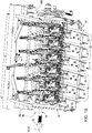
- a knotter table 10 provides a system for tying six loops of twine about a large parallelepiped bale formed in the baling chamber 86. It is noted that for different sizes of balers a knotter table for tying a different number of loops of twine may be used without departing from the principles of the present invention.
- the knotter table 10 for use with the large square baler 80 having a forward direction of travel as indicated by an arrow F.
- the knotter table 10 includes a support frame 12 comprising a bottom wall or floor 14 including L-shaped right- and left-hand bottom wall segments 14R and 14L respectively being formed by inwardly bent, L-shaped portions of right- and left-hand side walls 16R and 16L.
- the bottom wall further includes a plurality central bottom wall segments 18 comprising downwardly opening, longitudinally extending channel members that are spaced transversely from each other and from the short legs of the wall segments 14R and 14L to define a plurality of longitudinal needle slots 20 for respectively permitting a like number of twine-carrying needles (not shown) to swing upwardly through them during a tying cycle for securing a plurality of sets of twine strands together to form loops of twine about a bale formed in a baling chamber having a rear top region including a plurality of channel members 22 located within and supporting the knotter table bottom wall segments 18.
- a central component of the knotter table 10 is a knotter gear drive shaft 24 extending transversely to the direction of travel of the baler. Opposite end regions of the drive shaft 24 are respectively supported in bearing assemblies (not shown) including right and left bearing housings respectively mounted to the right and left vertical side walls 16R and 16L. Six identical knotter assemblies 26 are mounted at equally spaced locations across a middle region of the drive shaft 24.
- the knotter gear drive shaft 24 has a drive shaft axis 34 and a shaft outside diameter 36.
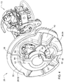
- each knotter assembly 26 includes a generally circular knotter gear 28.
- the knotter gear 28 of Fig. 2 is a two piece knotter gear including first and second knotter gear sectors 30 and 32.
- the first knotter gear sector 30 includes a first sector hub portion 38 and a first sector radial portion 40.
- a central passage 42 of the knotter assembly 26 is at least partially defined in the first sector hub portion 38 for receiving the knotter gear drive shaft 24.
- the first sector radial portion 40 extends radially outward from the first sector hub portion 38 relative to the drive shaft axis 34.
- a plurality of intermittent gear tooth segments 44 and 46 are defined on the first sector radial portion 40.
- a side 48 of the knotter gear 28 having the gear tooth segments thereon is referred to herein as the drive side 48 of the knotter gear 28, with the opposite side 50 being referred to herein as a back side of the knotter gear 28.
- the drive side 48 may be described as facing in a first axial direction parallel to shaft axis 34, and the back side 50 may be described as facing in a second axial direction opposite from the first axial direction.
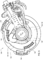
- the first sector hub portion 38 can be described as having a circumferential gap 52 (see Fig. 3 ) defined therein greater than the shaft outside diameter 36 such that the first knotter gear sector 30 is removable radially, relative to the drive shaft axis 34, from the knotter gear drive shaft 24.
- the circumferential gap 52 spans an arc of 180 degrees about the shaft axis 34.
- the second knotter gear sector 32 includes a second sector hub portion 54 and a second sector radial portion 56.
- the second sector hub portion 54 defines a further part of the central passage 42.
- the second sector radial portion 56 extends radially outward from the second sector hub portion 54 relative to the drive shaft axis 34.
- the second sector hub portion 54 can be described as closing or spanning in the circumferential gap 52 of the first sector hub portion 38 when the knotter assembly 26 is installed on the knotter gear drive shaft 24.
- first and second knotter gear sectors 30 and 32 each comprise substantially a 180 degree portion of the knotter assembly 26 relative to the drive shaft axis 34 such that the first and second knotter gear sectors 30 and 32 are divided from each other at a diametrical divide 58 extending substantially diametrically relative to the drive shaft axis 34.
- the first and second sector hub portions 38 and 54 include hub flanges 60 and 62, respectively, extending parallel to each other and parallel to the diametrical divide 58.
- the hub flanges 60 and 62 extend from the back side 50 of the first and second knotter gear sectors 30 and 32.
- At least one connector 64 extends between the hub flanges 60 and 62 and connects the first and second knotter gear sectors 30 and 32 when the knotter assembly 26 is installed on the knotter gear drive shaft 24.
- the first and second sector hub portions 38 and 54 can be described as being generally semi-cylindrical in shape such that when joined together they define the central passage 42 therethrough.
- the central passage 42 has a central axis 43 (see Fig. 3 ) which is coincident with the drive shaft axis 34.
- the second sector radial portion 56 has a second plurality of intermittent gear tooth segments 66 and 68 defined on its drive side.
- the central passage 42 is configured to closely receive the knotter gear drive shaft 24, and at least one of the first and second sector hub portions 38 and 54 includes an internal groove 70 which is keyed to the knotter gear drive shaft 24 such that the knotter gear 28 is rotationally fixed relative to the knotter gear drive shaft 24.
- Each knotter assembly 26 further includes a knotter frame 72 having an upper end defined by a two-piece cylindrical head frame assembly 74 received on the left end of the first and second sector hub portions 38 and 54 so as to permit the knotter gear 28 to rotate relative to the knotter frame 72.
- the head frame assembly 74 includes a main head frame portion 76 and a head frame cap 78 configured such that when the head frame cap 78 is bolted to the main head frame portion 76 the head frame assembly 74 circumscribes the knotter gear drive shaft 24 and the first and second sector hub portions 38 and 54.
- the head frame assembly 74 is configured such that the head frame cap 78 must be removed from the main head frame portion 76 to allow the first and second knotter gear sectors 30 and 32 to be removed radially, relative to the drive shaft axis 34 from the knotter gear drive shaft 24.
- an alternative embodiment of a knotter assembly is designated as 126 and includes a generally circular knotter gear 128.
- the knotter gear 128 of Fig. 5 is also a two piece knotter gear including first and second knotter gear sectors 130 and 132.
- the first knotter gear sector 130 includes a first sector radial portion 140 which circumscribes greater than 180 degrees relative to the drive shaft axis.
- the second sector radial portion 156 circumscribes less than 180 degrees relative to the drive shaft axis 34.
- Each of the first and second sector hub portions 138 and 154 still circumscribe substantially 180 degrees relative to the drive shaft axis. 34
- the first knotter gear sector 130 has a gap 152 defined therein which is larger than the shaft outside diameter 36 and thus permits the first knotter gear sector 130 to be removed radially relative to the knotter gear drive shaft 24 when the second knotter gear sector 132 is disconnected from the first knotter gear sector 130.
- the first knotter gear sector 130 may include a cast in boss 180 having a connector passage 182 defined therethrough transverse to the drive shaft axis 34.
- the second sector radial portion 156 of the second knotter gear sector 132 may have a threaded connector receptacle 184 defined therein and aligned with the connector passage 182.
- At least one connector 164 may extend through the connector passage 182 into the threaded connector receptacle 184 to connect the first and second sector radial portions 140 and 156.
- the boss 180 could be formed in the second knotter gear sector 132 and the threaded connector receptacle 184 could be formed in the first knotter gear sector 130.
- all of the intermittent gear tooth segments 144, 146, 166 and 168 are located on the first sector radial portion 140. In this embodiment there are no intermittent gear tooth segments on the second sector radial portion 156.
- Fig. 10 shows selected portions of another knotter assembly 226 including a two-piece knotter gear 228 including first and second substantially semi-circular knotter gear sectors 230 and 232, similar in many respects to the knotter gear 28 of Figs. 2-4 .
- the frame assembly 72 has been deleted in Fig. 10 for ease of illustration.
- the difference in the knotter assembly 226 of Fig. 10 lies in the manner in which the two knotter gear sectors are held together, and in the manner in which they are mounted on the drive shaft 24.
- the knotter assembly 226 of Fig. 10 further includes a circumferentially continuous inner hub 280 having an inner hub passage 282 which closely receives the knotter gear drive shaft 24 therein.
- the inner hub 280 is not radially removable from the knotter gear drive shaft 24.
- the inner hub 280 is received in the central passage of the first and second sector hub portions 238 and 254.
- the first and second sector hub portions 238 and 254 include radially extending sector hub flange portions 260 and 262, respectively.
- the inner hub includes a radially extending inner hub flange 284 which engages and is bolted to the radially extending sector hub flange portions 260 and 262 of the first and second sector hub portions 238 and 254, respectively, such that the first and second knotter gear sectors 230 and 232 are rotationally fixed relative to the inner hub 280.
- the radially extending sector hub flange portions 260 and 262 are located on the drive side of the knotter gear 228.
- a plurality of fasteners 264 may attach the radially extending inner hub flange 284 to the radially extending sector hub flange portions 260 and 262.
- Figs. 11 and 12 show another embodiment portions of a knotter assembly 326 similar to the knotter assembly of Fig. 10 , except in this case the radial flanges connecting the continuous inner hub and the first and second gear sectors are located on the back side of the knotter gear.
- the knotter assembly 326 includes first and second gear sectors 330 and 332.
- First gear sector 330 includes a first sector hub portion 338 and a first sector radial portion 340.
- Second gear sector 332 includes a second sector hub portion 354 and a second sector radial portion 356.
- On the back side of the first and second sector hub portions 338 and 354 are defined radially outwardly extending hub flanges, only the second radially outward extending hub flange 362 being visible in Fig. 11 .
- a circumferentially continuous inner hub 380 is received through the first and second sector hub portions 338 and 354 and includes radially extending inner hub flange 384 which may be bolted to the radially outwardly extending hub flanges such as 362.
- Fig. 13 shows a further knotter assembly 426 which includes a one piece knotter gear 428, which may be described as including one and only one knotter gear sector 430.
- the knotter gear sector 430 may be similar in construction to the first knotter gear sector 130 of the two piece knotter gear 128 of Figs. 5-9 , but in this case there is no second knotter gear sector to fill the gap in the first knotter gear sector.
- the one piece knotter gear sector 430 has an outer periphery 486 of its sector radial portion 440 which preferably circumscribes greater than 270 degrees about the drive shaft axis 34.
Landscapes
- Life Sciences & Earth Sciences (AREA)
- Environmental Sciences (AREA)
- Braiding, Manufacturing Of Bobbin-Net Or Lace, And Manufacturing Of Nets By Knotting (AREA)
- Gears, Cams (AREA)
Abstract
Description
- The present disclosure relates a knotter gear for use in a baler, and particularly to an intermittent knotter gear for use in a large square baler.
- Balers for producing parallelepiped bales in their baling chambers, so-called square balers, are equipped with knotter tables including a plurality of knotter assemblies mounted on a common knotter gear drive shaft. Each knotter assembly ties a twine loop about finished bales formed in bale chambers of the balers. Each knotter assembly includes a knotter gear which slides axially onto the knotter gear drive shaft.
- Should the knotter gear need to be replaced the entire knotter assembly must be removed axially from the knotter gear drive shaft along with additional mechanisms such as the tucker finger cam, brake, shaft support, bearing and other components. The time and effort required to remove the knotter gear and other mechanisms is significant.
- There is a need for improvements in the construction of such knotter assemblies that will reduce the amount of time and effort required to replace a broken or worn knotter gear.
- In one embodiment a knotter drive apparatus for a baler includes a knotter gear drive shaft having a drive shaft axis and a shaft outside diameter. A plurality of knotter assemblies are mounted on the knotter gear drive shaft. Each assembly includes a first knotter gear sector including a first sector hub portion and a first sector radial portion. The first sector hub portion includes a central passage at least partly defined in the first sector hub portion for receiving the knotter gear drive shaft. The first sector radial portion extends radially outward from the first sector hub portion relative to the drive shaft axis, and has defined thereon a plurality of intermittent gear tooth segments. The first sector hub portion has a circumferential gap defined therein greater than the shaft outside diameter such that the first knotter gear sector is removable radially, relative to the drive shaft axis, from the knotter gear drive shaft.
- In some embodiments the knotter assembly includes a two piece knotter gear including the first knotter gear sector and a second knotter gear sector.
- In other embodiments the knotter gear is a single piece knotter gear and the first knotter gear sector is the one and only one knotter gear sector.
- In another embodiment a knotter drive apparatus for a baler comprises first and second knotter gear sectors. The first knotter gear sector includes a first sector hub portion and a first sector radial portion. The second knotter gear sector includes a second sector hub portion and a second sector radial portion. The first and second sector hub portions are generally semi-cylindrical in shape such that when joined together the first and second sector hub portions define a central passage therethrough, the central passage having a central axis. The first sector radial portion extends radially outward from the first sector hub portion and has a plurality of intermittent gear tooth segments defined thereon. The second sector radial portion extends radially outward from the second sector hub portion.
- Numerous objects, features and advantages of the present invention will be readily apparent to those skilled in the art upon a reading of the following disclosure when taken in conjunction with the accompanying drawings.
-
-
Fig. 1A is a left rear perspective view of a large square baler. -
Fig. 1B is a right rear perspective view of a portion of the knotter table of the large square baler ofFig. 1A embodying knotter assemblies having knotter gears constructed in accordance with the present invention. -
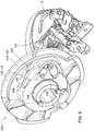
Fig. 2 is a drive side perspective view of a knotter assembly including a first embodiment of a two piece knotter gear. -
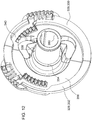
Fig. 3 is a back side elevation view of the knotter assembly ofFig. 2 . -
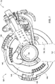
Fig. 4 is a back side perspective view of the knotter assembly ofFig. 2 . -
Fig. 5 is a drive side perspective view of a knotter assembly including a second embodiment of a two piece knotter gear. -
Fig. 6 is a back side elevation view of the knotter assembly ofFig. 5 with the second knotter gear sector removed. -
Fig. 7 is a front side elevation view of the knotter assembly ofFig. 5 with the second knotter gear sector removed. -
Fig. 8 is a drive side perspective view of the second knotter gear sector removed from the knotter assembly ofFig. 5 . -
Fig. 9 is a back side perspective view of the two piece knotter gear ofFig. 5 having a cast in boss for a fastener to hold the first and second knotter gear sectors together. -
Fig. 10 is a drive side perspective view of a third embodiment of a two piece knotter gear including a separate inner hub. -
Fig. 11 is a back side perspective view of a fourth embodiment of a two piece knotter gear including a separate inner hub. -
Fig. 12 is a drive side perspective view of the knotter gear ofFig. 11 . -
Fig. 13 is a drive side elevation view of a fifth embodiment of a radially removable knotter gear having one and only one knotter gear sector. - Preliminarily, it is to be noted that the terms "right" and "left" are in accordance with an observer standing behind and facing in a forward direction of travel of a baler equipped with a tying table constructed in accordance with the present invention.
- Referring now to
Fig. 1A , there is shown a largesquare baler 80 including amain frame 82 supported onground wheels 84 for being towed across a field containing windrows of crop to be baled. Themain frame 82 includes abaling chamber 86 extending longitudinally from a forward central location of thebaler 80. A crop pick-up andconditioning arrangement 88 is provided at a front underside location of themain frame 82 and feeds gathered crop through acrop delivery chute 90 that curves upwardly and rearwardly from the pick-up andconditioning arrangement 88 and delivers crop through an opening (not shown) provided in the baling chamber bottom wall from where it is periodically engaged by a reciprocating plunger (not shown) and pushed to the rear to form a compressed bale of crop. A knotter table 10 provides a system for tying six loops of twine about a large parallelepiped bale formed in thebaling chamber 86. It is noted that for different sizes of balers a knotter table for tying a different number of loops of twine may be used without departing from the principles of the present invention. - Referring now to
Fig. 1B , an enlarged view is shown of the knotter table 10 for use with the largesquare baler 80 having a forward direction of travel as indicated by an arrow F. The knotter table 10 includes asupport frame 12 comprising a bottom wall orfloor 14 including L-shaped right- and left-handbottom wall segments hand side walls bottom wall segments 18 comprising downwardly opening, longitudinally extending channel members that are spaced transversely from each other and from the short legs of thewall segments longitudinal needle slots 20 for respectively permitting a like number of twine-carrying needles (not shown) to swing upwardly through them during a tying cycle for securing a plurality of sets of twine strands together to form loops of twine about a bale formed in a baling chamber having a rear top region including a plurality ofchannel members 22 located within and supporting the knotter tablebottom wall segments 18. - A central component of the knotter table 10 is a knotter
gear drive shaft 24 extending transversely to the direction of travel of the baler. Opposite end regions of thedrive shaft 24 are respectively supported in bearing assemblies (not shown) including right and left bearing housings respectively mounted to the right and leftvertical side walls identical knotter assemblies 26 are mounted at equally spaced locations across a middle region of thedrive shaft 24. The knottergear drive shaft 24 has a drive shaft axis 34 and a shaft outsidediameter 36. - Referring now to
Fig. 2 , eachknotter assembly 26 includes a generally circular knotter gear 28. The knotter gear 28 ofFig. 2 is a two piece knotter gear including first and second knotter gear sectors 30 and 32. - The first knotter gear sector 30 includes a first
sector hub portion 38 and a first sectorradial portion 40. Acentral passage 42 of theknotter assembly 26 is at least partially defined in the firstsector hub portion 38 for receiving the knottergear drive shaft 24. The first sectorradial portion 40 extends radially outward from the firstsector hub portion 38 relative to the drive shaft axis 34. A plurality of intermittentgear tooth segments radial portion 40. A side 48 of the knotter gear 28 having the gear tooth segments thereon is referred to herein as the drive side 48 of the knotter gear 28, with theopposite side 50 being referred to herein as a back side of the knotter gear 28. The drive side 48 may be described as facing in a first axial direction parallel to shaft axis 34, and theback side 50 may be described as facing in a second axial direction opposite from the first axial direction. - The first
sector hub portion 38 can be described as having a circumferential gap 52 (seeFig. 3 ) defined therein greater than the shaft outsidediameter 36 such that the first knotter gear sector 30 is removable radially, relative to the drive shaft axis 34, from the knottergear drive shaft 24. In the embodiment ofFigs. 2-4 thecircumferential gap 52 spans an arc of 180 degrees about the shaft axis 34. - The second knotter gear sector 32 includes a second
sector hub portion 54 and a second sector radial portion 56. The secondsector hub portion 54 defines a further part of thecentral passage 42. The second sector radial portion 56 extends radially outward from the secondsector hub portion 54 relative to the drive shaft axis 34. The secondsector hub portion 54 can be described as closing or spanning in thecircumferential gap 52 of the firstsector hub portion 38 when theknotter assembly 26 is installed on the knottergear drive shaft 24. - In the embodiment of
Figs. 2-4 the first and second knotter gear sectors 30 and 32 each comprise substantially a 180 degree portion of theknotter assembly 26 relative to the drive shaft axis 34 such that the first and second knotter gear sectors 30 and 32 are divided from each other at adiametrical divide 58 extending substantially diametrically relative to the drive shaft axis 34. The first and secondsector hub portions hub flanges diametrical divide 58. The hub flanges 60 and 62 extend from theback side 50 of the first and second knotter gear sectors 30 and 32. At least oneconnector 64 extends between thehub flanges knotter assembly 26 is installed on the knottergear drive shaft 24. - The first and second
sector hub portions central passage 42 therethrough. Thecentral passage 42 has a central axis 43 (seeFig. 3 ) which is coincident with the drive shaft axis 34. - In the embodiment of
Figs. 2-4 the second sector radial portion 56 has a second plurality of intermittentgear tooth segments - In the embodiment of
Figs. 2-4 thecentral passage 42 is configured to closely receive the knottergear drive shaft 24, and at least one of the first and secondsector hub portions internal groove 70 which is keyed to the knottergear drive shaft 24 such that the knotter gear 28 is rotationally fixed relative to the knottergear drive shaft 24. - Each
knotter assembly 26 further includes aknotter frame 72 having an upper end defined by a two-piece cylindrical head frame assembly 74 received on the left end of the first and secondsector hub portions knotter frame 72. The head frame assembly 74 includes a main head frame portion 76 and a head frame cap 78 configured such that when the head frame cap 78 is bolted to the main head frame portion 76 the head frame assembly 74 circumscribes the knottergear drive shaft 24 and the first and secondsector hub portions gear drive shaft 24. - Referring now to
Fig. 5 , an alternative embodiment of a knotter assembly is designated as 126 and includes a generally circular knotter gear 128. The knotter gear 128 ofFig. 5 is also a two piece knotter gear including first and second knotter gear sectors 130 and 132. In this case the first knotter gear sector 130 includes a firstsector radial portion 140 which circumscribes greater than 180 degrees relative to the drive shaft axis. The secondsector radial portion 156 circumscribes less than 180 degrees relative to the drive shaft axis 34. Each of the first and secondsector hub portions - The first knotter gear sector 130 has a
gap 152 defined therein which is larger than the shaft outsidediameter 36 and thus permits the first knotter gear sector 130 to be removed radially relative to the knottergear drive shaft 24 when the second knotter gear sector 132 is disconnected from the first knotter gear sector 130. - As best shown in
Fig. 9 , the first knotter gear sector 130 may include a cast inboss 180 having aconnector passage 182 defined therethrough transverse to the drive shaft axis 34. The secondsector radial portion 156 of the second knotter gear sector 132 may have a threadedconnector receptacle 184 defined therein and aligned with theconnector passage 182. At least oneconnector 164 may extend through theconnector passage 182 into the threadedconnector receptacle 184 to connect the first and secondsector radial portions boss 180 could be formed in the second knotter gear sector 132 and the threadedconnector receptacle 184 could be formed in the first knotter gear sector 130. - Also, in the knotter gear 128 all of the intermittent
gear tooth segments sector radial portion 140. In this embodiment there are no intermittent gear tooth segments on the secondsector radial portion 156. -
Fig. 10 shows selected portions of anotherknotter assembly 226 including a two-piece knotter gear 228 including first and second substantially semi-circular knotter gear sectors 230 and 232, similar in many respects to the knotter gear 28 ofFigs. 2-4 . Theframe assembly 72 has been deleted inFig. 10 for ease of illustration. The difference in theknotter assembly 226 ofFig. 10 lies in the manner in which the two knotter gear sectors are held together, and in the manner in which they are mounted on thedrive shaft 24. - The
knotter assembly 226 ofFig. 10 further includes a circumferentially continuousinner hub 280 having aninner hub passage 282 which closely receives the knottergear drive shaft 24 therein. Theinner hub 280 is not radially removable from the knottergear drive shaft 24. Theinner hub 280 is received in the central passage of the first and secondsector hub portions sector hub portions hub flange portions inner hub flange 284 which engages and is bolted to the radially extending sectorhub flange portions sector hub portions inner hub 280. - In the embodiment of
Fig. 10 the radially extending sectorhub flange portions fasteners 264 may attach the radially extendinginner hub flange 284 to the radially extending sectorhub flange portions -
Figs. 11 and12 show another embodiment portions of aknotter assembly 326 similar to the knotter assembly ofFig. 10 , except in this case the radial flanges connecting the continuous inner hub and the first and second gear sectors are located on the back side of the knotter gear. - In
Figs. 11 and12 theknotter assembly 326 includes first and second gear sectors 330 and 332. First gear sector 330 includes a firstsector hub portion 338 and a firstsector radial portion 340. Second gear sector 332 includes a secondsector hub portion 354 and a secondsector radial portion 356. On the back side of the first and secondsector hub portions hub flange 362 being visible inFig. 11 . - A circumferentially continuous
inner hub 380 is received through the first and secondsector hub portions inner hub flange 384 which may be bolted to the radially outwardly extending hub flanges such as 362. -
Fig. 13 shows afurther knotter assembly 426 which includes a one piece knotter gear 428, which may be described as including one and only one knotter gear sector 430. - The knotter gear sector 430 may be similar in construction to the first knotter gear sector 130 of the two piece knotter gear 128 of
Figs. 5-9 , but in this case there is no second knotter gear sector to fill the gap in the first knotter gear sector. - The one piece knotter gear sector 430 has an
outer periphery 486 of itssector radial portion 440 which preferably circumscribes greater than 270 degrees about the drive shaft axis 34. - Thus, it is seen that the apparatus and methods of the present disclosure readily achieve the ends and advantages mentioned as well as those inherent therein. While certain preferred embodiments of the disclosure have been illustrated and described for present purposes, numerous changes in the arrangement and construction of parts and steps may be made by those skilled in the art, which changes are encompassed within the scope and spirit of the present disclosure as defined by the appended claims. Each disclosed feature or embodiment may be combined with any of the other disclosed features or embodiments.
Claims (15)
- A knotter drive apparatus for a baler, comprising: a knotter gear drive shaft (24) having a drive shaft axis (34) and a shaft outside diameter (36); and a plurality of knotter assemblies (26, 126, 226, 326, 426) mounted on the knotter gear drive shaft (24), each knotter assembly including a first knotter gear sector (30, 130, 230, 330, 430) including a first sector hub portion (38, 138, 238, 338) and a first sector radial portion (40, 140, 240, 340, 440), wherein: a central passage (42) of the knotter assembly is at least partly defined in the first sector hub portion (38) for receiving the knotter gear drive shaft (24); the first sector radial portion (40) extends radially outward from the first sector hub portion (38) relative to the drive shaft axis (34), and has defined thereon a plurality of intermittent gear tooth segments (44, 46); and the first knotter gear sector (30) has a circumferential gap (52) defined therein greater than the shaft outside diameter (36) such that the first knotter gear sector (30) is removable radially, relative to the drive shaft axis (24), from the knotter gear drive shaft (24).
- The knotter drive apparatus of claim 1, wherein each knotter assembly further comprises:a second knotter gear sector (32) including a second sector hub portion (54) and a second sector radial portion (56), wherein:the second sector hub portion (54) defines a further part of the central passage (42);the second sector radial portion (56) extends radially outward from the second sector hub portion (54) relative to the drive shaft axis (34);the second knotter gear sector (32) closes the circumferential gap (52) of the first knotter gear sector (30) when the knotter assembly is installed on the knotter gear drive shaft (24); and at least one connector (64) connects the first and second knotter gear sectors when the knotter assembly is installed on the knotter gear drive shaft.
- The knotter drive apparatus of claim 1 or 2, wherein: the first and second knotter gear sectors (30, 32) each comprise substantially a 180 degree portion of the knotter assembly relative to the drive shaft axis (34) such that the first and second knotter gear sectors are divided from each other at a diametrical divide (58) extending substantially diametrically relative to the drive shaft axis.
- The knotter drive apparatus according to at least one of the claims 1 to 3, wherein: the first sector hub portion (38) and the second sector hub portion (54) each include hub flanges (60, 62) extending parallel to each other and parallel to the diametrical divide (58); and the at least one connector (64) connects the hub flanges.
- The knotter drive apparatus according to at least one of the claims 1 to 4, wherein: the second sector radial portion (56) has defined thereon a second plurality of intermittent gear tooth segments (66, 68); each of the first and second sector radial portions (40, 56) has a drive side (48) facing in a first axial direction and a back side (50) facing in a second axial direction opposite the first axial direction, the respective pluralities of intermittent gear tooth segments being located on the drive sides of the respective first and second sector radial portions; and the hub flanges (60, 62) of the first and second sector hub portions (38, 54) extend from the back sides of the respective first and second sector radial portions.
- The knotter drive apparatus according to at least one of the claims 1 to 5, wherein: the central passage (42) is configured to closely receive the knotter gear drive shaft (24); and at least one of the first and second sector hub portions (38, 54) includes an internal groove (70) keyed to the knotter gear drive shaft (24) such that the knotter assembly is rotationally fixed relative to the knotter gear drive shaft.
- The knotter drive apparatus according to at least one of the claims 1 to 6, wherein: the first sector radial portion (40) circumscribes greater than 180 degrees relative to the drive shaft axis; and the second sector radial portion (56) circumscribes less than 180 degrees relative to the drive shaft axis.
- The knotter drive apparatus according to at least one of the claims 1 to 7, wherein: all of the intermittent gear tooth segments (44, 46, 66, 68) of the knotter assembly are located on the first sector radial portion (40).
- The knotter drive apparatus according to at least one of the claims 1 to 8, wherein: the first and second sector hub portions (38, 54) each circumscribe substantially 180 degrees relative to the drive shaft axis (34).
- The knotter drive apparatus according to at least one of the claims 1 to 9, wherein: one of the first and second sector radial portions (40, 56) includes a boss (180) having a connector passage (182) defined therethrough transverse to the drive shaft axis (34); the other of the first and second sector radial portions has a threaded connector receptacle (184) defined therein and aligned with the connector passage (182); and the at least one connector (64) extends through the connector passage into the threaded connector receptacle to connect the first and second sector radial portions.
- The knotter drive apparatus according to at least one of the claims 1 to 10, wherein: each knotter assembly (226, 326) further includes a circumferentially continuous inner hub (280, 380) having the knotter gear drive shaft (24) closely received in the inner hub so that the inner hub is not radially removable from the knotter gear drive shaft; the inner hub is received in the central passage (42) defined by the first and second sector hub portions (238. 254. 338. 354); each of the first and second sector hub portions includes a radially extending sector hub flange portion (260, 262, 362); and the inner hub includes a radially extending inner hub flange (284, 384) engaging and bolted to the radially extending sector hub flange portions such that the first and second knotter gear sectors are rotationally fixed relative to the inner hub.
- The knotter drive apparatus according to at least one of the claims 1 to 11, wherein: the first and second knotter gear sectors (230, 232, 330, 332) each comprise substantially a 180 degree portion of the knotter assembly (226, 326) relative to the drive shaft axis (34) such that the first and second knotter gear sectors are divided from each other at a diametrical divide (58) extending substantially diametrically relative to the drive shaft axis (34).
- The knotter drive apparatus according to at least one of the claims 1 to 12, wherein: the second sector radial portion has defined thereon a second plurality of intermittent gear tooth segments; each of the first and second sector radial portions has a drive side facing in a first axial direction and a back side facing in a second axial direction opposite the first axial direction, the respective pluralities of intermittent gear tooth segments being located on the drive sides of the respective first and second sector radial portions; and the radially extending sector hub flange portions (260, 262) of the first and second sector hub portions are spaced in the first axial direction from the first and second sector radial portions.
- The knotter drive apparatus according to at least one of the claims 1 to 13, wherein: the second sector radial portion (356) has defined thereon a second plurality of intermittent gear tooth segments; each of the first and second sector radial portions has a drive side facing in a first axial direction and a back side facing in a second axial direction opposite the first axial direction, the respective pluralities of intermittent gear tooth segments being located on the drive sides of the respective first and second sector radial portions; and the radially extending sector hub flange portions (362) of the first and second sector hub portions (338, 354) are spaced in the second axial direction from the first and second sector radial portions.
- The knotter drive apparatus according to at least one of the claims 1 to 14, wherein: the first knotter gear sector (430) is the one and only one knotter gear sector of each knotter assembly (426), and a radially outer periphery of the first knotter gear sector circumscribes greater than 270 degrees about the drive shaft axis.
Applications Claiming Priority (1)
| Application Number | Priority Date | Filing Date | Title |
|---|---|---|---|
| US16/918,120 US11606908B2 (en) | 2020-07-01 | 2020-07-01 | Intermittent knotter gear |
Publications (2)
| Publication Number | Publication Date |
|---|---|
| EP3932184A1 true EP3932184A1 (en) | 2022-01-05 |
| EP3932184B1 EP3932184B1 (en) | 2025-01-22 |
Family
ID=76483026
Family Applications (1)
| Application Number | Title | Priority Date | Filing Date |
|---|---|---|---|
| EP21179375.7A Active EP3932184B1 (en) | 2020-07-01 | 2021-06-15 | Intermittent knotter gear |
Country Status (2)
| Country | Link |
|---|---|
| US (1) | US11606908B2 (en) |
| EP (1) | EP3932184B1 (en) |
Cited By (1)
| Publication number | Priority date | Publication date | Assignee | Title |
|---|---|---|---|---|
| EP4417038A1 (en) * | 2023-02-14 | 2024-08-21 | Maschinenfabrik Bernard Krone GmbH & Co. KG | Tying arrangement for a baler |
Families Citing this family (1)
| Publication number | Priority date | Publication date | Assignee | Title |
|---|---|---|---|---|
| US12302797B1 (en) * | 2023-11-07 | 2025-05-20 | Great Plains Manufacturing, Inc. | Locking mechanism for knotter assemblies |
Citations (3)
| Publication number | Priority date | Publication date | Assignee | Title |
|---|---|---|---|---|
| DE19819595A1 (en) * | 1998-04-30 | 1999-11-04 | Case Harvesting Sys Gmbh | Tying apparatus for balers |
| EP2260693A1 (en) * | 2009-06-08 | 2010-12-15 | Deere & Company | Knotter Arrangement |
| DE202009019023U1 (en) * | 2009-11-03 | 2015-08-10 | Rasspe Systemtechnik GmbH | Double knot yarn knotter unit for large pack presses with multiple knot yarn knots combined on a knotter drive shaft |
Family Cites Families (5)
| Publication number | Priority date | Publication date | Assignee | Title |
|---|---|---|---|---|
| US5829346A (en) * | 1997-06-25 | 1998-11-03 | Ast; Gene | Bale twine tensioner |
| US6957835B2 (en) | 2003-11-21 | 2005-10-25 | Deere & Company | Device for adjusting the space between adjacent knotter assemblies on a knotter drive shaft |
| US8590945B2 (en) * | 2009-11-03 | 2013-11-26 | Rasspe Systemtechnik GMBH & Co., KG | Double-knot twine-knotter unit for large bale presses with a plurality of double-knot twine-knotters assembled on one knotter driveshaft |
| US8671834B1 (en) | 2012-11-30 | 2014-03-18 | Deere & Company | Twine tensioner arm position sensor arrangement |
| US9807941B2 (en) | 2014-04-25 | 2017-11-07 | Deere & Company | Tucker finger over-center protection |
-
2020
- 2020-07-01 US US16/918,120 patent/US11606908B2/en active Active
-
2021
- 2021-06-15 EP EP21179375.7A patent/EP3932184B1/en active Active
Patent Citations (3)
| Publication number | Priority date | Publication date | Assignee | Title |
|---|---|---|---|---|
| DE19819595A1 (en) * | 1998-04-30 | 1999-11-04 | Case Harvesting Sys Gmbh | Tying apparatus for balers |
| EP2260693A1 (en) * | 2009-06-08 | 2010-12-15 | Deere & Company | Knotter Arrangement |
| DE202009019023U1 (en) * | 2009-11-03 | 2015-08-10 | Rasspe Systemtechnik GmbH | Double knot yarn knotter unit for large pack presses with multiple knot yarn knots combined on a knotter drive shaft |
Cited By (1)
| Publication number | Priority date | Publication date | Assignee | Title |
|---|---|---|---|---|
| EP4417038A1 (en) * | 2023-02-14 | 2024-08-21 | Maschinenfabrik Bernard Krone GmbH & Co. KG | Tying arrangement for a baler |
Also Published As
| Publication number | Publication date |
|---|---|
| US20220000033A1 (en) | 2022-01-06 |
| US11606908B2 (en) | 2023-03-21 |
| EP3932184B1 (en) | 2025-01-22 |
Similar Documents
| Publication | Publication Date | Title |
|---|---|---|
| EP3932184B1 (en) | Intermittent knotter gear | |
| EP3108741A1 (en) | Pick-up device of a forage implement | |
| US8069780B2 (en) | Modular baler plunger | |
| EP3075225B1 (en) | Pickup unit with a windrow conditioning roll for an agricultural baler | |
| EA023784B1 (en) | Double-knot twine-knotter unit and large bale press with twine tying having a plurality of double-knot twine knotters combined on one knotter drive shaft | |
| BE1024103B1 (en) | BALING PRESS FOR AGRICULTURAL APPLICATIONS WITH EXTENDED BALE EMISSION SYSTEM | |
| EP1537771A1 (en) | Transversal screw conveyor for a harvesting attachment | |
| US20130167501A1 (en) | Camless pickup wrapper | |
| EP3760033B1 (en) | Needle frame yoke and arm assembly for agricultural machine | |
| EP2901847B1 (en) | Agricultural baler with a plunger slot belt | |
| EP3760034B1 (en) | Needle frame assembly and needle coupling for agricultural machine | |
| US11617307B2 (en) | Net guide for upper rollers of round baler | |
| US11974521B2 (en) | Bale chamber arrangement for an agricultural baler | |
| US11240965B2 (en) | Multi-material needle for square balers | |
| BE1026406B1 (en) | AXIS SET-UP FOR AN AGRICULTURAL BALL PRESS | |
| US20130327234A1 (en) | Blower Arrangement For An Agricultural Baler | |
| US12376529B2 (en) | Baler implement with twine delivery system | |
| CN206341610U (en) | Sheller unit | |
| WO2024261573A1 (en) | Agricultural baler | |
| US11457567B2 (en) | Needle coupling and frame assembly for agricultural machine | |
| WO2024105461A1 (en) | Double baler chamber divider | |
| EP4727337A1 (en) | Agricultural baler | |
| WO2024261574A1 (en) | Agricultural baler |
Legal Events
| Date | Code | Title | Description |
|---|---|---|---|
| PUAI | Public reference made under article 153(3) epc to a published international application that has entered the european phase |
Free format text: ORIGINAL CODE: 0009012 |
|
| STAA | Information on the status of an ep patent application or granted ep patent |
Free format text: STATUS: THE APPLICATION HAS BEEN PUBLISHED |
|
| AK | Designated contracting states |
Kind code of ref document: A1 Designated state(s): AL AT BE BG CH CY CZ DE DK EE ES FI FR GB GR HR HU IE IS IT LI LT LU LV MC MK MT NL NO PL PT RO RS SE SI SK SM TR |
|
| B565 | Issuance of search results under rule 164(2) epc |
Effective date: 20211130 |
|
| STAA | Information on the status of an ep patent application or granted ep patent |
Free format text: STATUS: REQUEST FOR EXAMINATION WAS MADE |
|
| 17P | Request for examination filed |
Effective date: 20220705 |
|
| RBV | Designated contracting states (corrected) |
Designated state(s): AL AT BE BG CH CY CZ DE DK EE ES FI FR GB GR HR HU IE IS IT LI LT LU LV MC MK MT NL NO PL PT RO RS SE SI SK SM TR |
|
| GRAP | Despatch of communication of intention to grant a patent |
Free format text: ORIGINAL CODE: EPIDOSNIGR1 |
|
| STAA | Information on the status of an ep patent application or granted ep patent |
Free format text: STATUS: GRANT OF PATENT IS INTENDED |
|
| RIC1 | Information provided on ipc code assigned before grant |
Ipc: A01F 15/14 20060101AFI20240715BHEP |
|
| GRAJ | Information related to disapproval of communication of intention to grant by the applicant or resumption of examination proceedings by the epo deleted |
Free format text: ORIGINAL CODE: EPIDOSDIGR1 |
|
| GRAP | Despatch of communication of intention to grant a patent |
Free format text: ORIGINAL CODE: EPIDOSNIGR1 |
|
| GRAJ | Information related to disapproval of communication of intention to grant by the applicant or resumption of examination proceedings by the epo deleted |
Free format text: ORIGINAL CODE: EPIDOSDIGR1 |
|
| STAA | Information on the status of an ep patent application or granted ep patent |
Free format text: STATUS: REQUEST FOR EXAMINATION WAS MADE |
|
| GRAJ | Information related to disapproval of communication of intention to grant by the applicant or resumption of examination proceedings by the epo deleted |
Free format text: ORIGINAL CODE: EPIDOSDIGR1 |
|
| STAA | Information on the status of an ep patent application or granted ep patent |
Free format text: STATUS: GRANT OF PATENT IS INTENDED |
|
| GRAP | Despatch of communication of intention to grant a patent |
Free format text: ORIGINAL CODE: EPIDOSNIGR1 |
|
| GRAJ | Information related to disapproval of communication of intention to grant by the applicant or resumption of examination proceedings by the epo deleted |
Free format text: ORIGINAL CODE: EPIDOSDIGR1 |
|
| STAA | Information on the status of an ep patent application or granted ep patent |
Free format text: STATUS: REQUEST FOR EXAMINATION WAS MADE |
|
| GRAP | Despatch of communication of intention to grant a patent |
Free format text: ORIGINAL CODE: EPIDOSNIGR1 |
|
| STAA | Information on the status of an ep patent application or granted ep patent |
Free format text: STATUS: GRANT OF PATENT IS INTENDED |
|
| INTG | Intention to grant announced |
Effective date: 20240827 |
|
| INTG | Intention to grant announced |
Effective date: 20240903 |
|
| INTC | Intention to grant announced (deleted) | ||
| INTG | Intention to grant announced |
Effective date: 20240920 |
|
| GRAS | Grant fee paid |
Free format text: ORIGINAL CODE: EPIDOSNIGR3 |
|
| GRAA | (expected) grant |
Free format text: ORIGINAL CODE: 0009210 |
|
| STAA | Information on the status of an ep patent application or granted ep patent |
Free format text: STATUS: THE PATENT HAS BEEN GRANTED |
|
| AK | Designated contracting states |
Kind code of ref document: B1 Designated state(s): AL AT BE BG CH CY CZ DE DK EE ES FI FR GB GR HR HU IE IS IT LI LT LU LV MC MK MT NL NO PL PT RO RS SE SI SK SM TR |
|
| REG | Reference to a national code |
Ref country code: GB Ref legal event code: FG4D |
|
| REG | Reference to a national code |
Ref country code: CH Ref legal event code: EP |
|
| REG | Reference to a national code |
Ref country code: IE Ref legal event code: FG4D |
|
| REG | Reference to a national code |
Ref country code: DE Ref legal event code: R096 Ref document number: 602021025066 Country of ref document: DE |
|
| REG | Reference to a national code |
Ref country code: NL Ref legal event code: MP Effective date: 20250122 |
|
| PG25 | Lapsed in a contracting state [announced via postgrant information from national office to epo] |
Ref country code: NL Free format text: LAPSE BECAUSE OF FAILURE TO SUBMIT A TRANSLATION OF THE DESCRIPTION OR TO PAY THE FEE WITHIN THE PRESCRIBED TIME-LIMIT Effective date: 20250122 |
|
| PG25 | Lapsed in a contracting state [announced via postgrant information from national office to epo] |
Ref country code: RS Free format text: LAPSE BECAUSE OF FAILURE TO SUBMIT A TRANSLATION OF THE DESCRIPTION OR TO PAY THE FEE WITHIN THE PRESCRIBED TIME-LIMIT Effective date: 20250422 |
|
| PG25 | Lapsed in a contracting state [announced via postgrant information from national office to epo] |
Ref country code: FI Free format text: LAPSE BECAUSE OF FAILURE TO SUBMIT A TRANSLATION OF THE DESCRIPTION OR TO PAY THE FEE WITHIN THE PRESCRIBED TIME-LIMIT Effective date: 20250122 |
|
| PG25 | Lapsed in a contracting state [announced via postgrant information from national office to epo] |
Ref country code: PL Free format text: LAPSE BECAUSE OF FAILURE TO SUBMIT A TRANSLATION OF THE DESCRIPTION OR TO PAY THE FEE WITHIN THE PRESCRIBED TIME-LIMIT Effective date: 20250122 |
|
| PGFP | Annual fee paid to national office [announced via postgrant information from national office to epo] |
Ref country code: DE Payment date: 20250521 Year of fee payment: 5 |
|
| PG25 | Lapsed in a contracting state [announced via postgrant information from national office to epo] |
Ref country code: ES Free format text: LAPSE BECAUSE OF FAILURE TO SUBMIT A TRANSLATION OF THE DESCRIPTION OR TO PAY THE FEE WITHIN THE PRESCRIBED TIME-LIMIT Effective date: 20250122 |
|
| REG | Reference to a national code |
Ref country code: LT Ref legal event code: MG9D |
|
| PG25 | Lapsed in a contracting state [announced via postgrant information from national office to epo] |
Ref country code: NO Free format text: LAPSE BECAUSE OF FAILURE TO SUBMIT A TRANSLATION OF THE DESCRIPTION OR TO PAY THE FEE WITHIN THE PRESCRIBED TIME-LIMIT Effective date: 20250422 Ref country code: IS Free format text: LAPSE BECAUSE OF FAILURE TO SUBMIT A TRANSLATION OF THE DESCRIPTION OR TO PAY THE FEE WITHIN THE PRESCRIBED TIME-LIMIT Effective date: 20250522 |
|
| REG | Reference to a national code |
Ref country code: AT Ref legal event code: MK05 Ref document number: 1760692 Country of ref document: AT Kind code of ref document: T Effective date: 20250122 |
|
| PG25 | Lapsed in a contracting state [announced via postgrant information from national office to epo] |
Ref country code: HR Free format text: LAPSE BECAUSE OF FAILURE TO SUBMIT A TRANSLATION OF THE DESCRIPTION OR TO PAY THE FEE WITHIN THE PRESCRIBED TIME-LIMIT Effective date: 20250122 |
|
| PG25 | Lapsed in a contracting state [announced via postgrant information from national office to epo] |
Ref country code: PT Free format text: LAPSE BECAUSE OF FAILURE TO SUBMIT A TRANSLATION OF THE DESCRIPTION OR TO PAY THE FEE WITHIN THE PRESCRIBED TIME-LIMIT Effective date: 20250522 Ref country code: LV Free format text: LAPSE BECAUSE OF FAILURE TO SUBMIT A TRANSLATION OF THE DESCRIPTION OR TO PAY THE FEE WITHIN THE PRESCRIBED TIME-LIMIT Effective date: 20250122 |
|
| PGFP | Annual fee paid to national office [announced via postgrant information from national office to epo] |
Ref country code: FR Payment date: 20250625 Year of fee payment: 5 |
|
| PG25 | Lapsed in a contracting state [announced via postgrant information from national office to epo] |
Ref country code: GR Free format text: LAPSE BECAUSE OF FAILURE TO SUBMIT A TRANSLATION OF THE DESCRIPTION OR TO PAY THE FEE WITHIN THE PRESCRIBED TIME-LIMIT Effective date: 20250423 Ref country code: BG Free format text: LAPSE BECAUSE OF FAILURE TO SUBMIT A TRANSLATION OF THE DESCRIPTION OR TO PAY THE FEE WITHIN THE PRESCRIBED TIME-LIMIT Effective date: 20250122 |
|
| PG25 | Lapsed in a contracting state [announced via postgrant information from national office to epo] |
Ref country code: AT Free format text: LAPSE BECAUSE OF FAILURE TO SUBMIT A TRANSLATION OF THE DESCRIPTION OR TO PAY THE FEE WITHIN THE PRESCRIBED TIME-LIMIT Effective date: 20250122 |
|
| PG25 | Lapsed in a contracting state [announced via postgrant information from national office to epo] |
Ref country code: SE Free format text: LAPSE BECAUSE OF FAILURE TO SUBMIT A TRANSLATION OF THE DESCRIPTION OR TO PAY THE FEE WITHIN THE PRESCRIBED TIME-LIMIT Effective date: 20250122 |
|
| PG25 | Lapsed in a contracting state [announced via postgrant information from national office to epo] |
Ref country code: SM Free format text: LAPSE BECAUSE OF FAILURE TO SUBMIT A TRANSLATION OF THE DESCRIPTION OR TO PAY THE FEE WITHIN THE PRESCRIBED TIME-LIMIT Effective date: 20250122 |
|
| PG25 | Lapsed in a contracting state [announced via postgrant information from national office to epo] |
Ref country code: DK Free format text: LAPSE BECAUSE OF FAILURE TO SUBMIT A TRANSLATION OF THE DESCRIPTION OR TO PAY THE FEE WITHIN THE PRESCRIBED TIME-LIMIT Effective date: 20250122 |
|
| PG25 | Lapsed in a contracting state [announced via postgrant information from national office to epo] |
Ref country code: IT Free format text: LAPSE BECAUSE OF FAILURE TO SUBMIT A TRANSLATION OF THE DESCRIPTION OR TO PAY THE FEE WITHIN THE PRESCRIBED TIME-LIMIT Effective date: 20250122 |
|
| PG25 | Lapsed in a contracting state [announced via postgrant information from national office to epo] |
Ref country code: EE Free format text: LAPSE BECAUSE OF FAILURE TO SUBMIT A TRANSLATION OF THE DESCRIPTION OR TO PAY THE FEE WITHIN THE PRESCRIBED TIME-LIMIT Effective date: 20250122 Ref country code: CZ Free format text: LAPSE BECAUSE OF FAILURE TO SUBMIT A TRANSLATION OF THE DESCRIPTION OR TO PAY THE FEE WITHIN THE PRESCRIBED TIME-LIMIT Effective date: 20250122 |
|
| REG | Reference to a national code |
Ref country code: DE Ref legal event code: R097 Ref document number: 602021025066 Country of ref document: DE |
|
| PG25 | Lapsed in a contracting state [announced via postgrant information from national office to epo] |
Ref country code: RO Free format text: LAPSE BECAUSE OF FAILURE TO SUBMIT A TRANSLATION OF THE DESCRIPTION OR TO PAY THE FEE WITHIN THE PRESCRIBED TIME-LIMIT Effective date: 20250122 |
|
| PG25 | Lapsed in a contracting state [announced via postgrant information from national office to epo] |
Ref country code: SK Free format text: LAPSE BECAUSE OF FAILURE TO SUBMIT A TRANSLATION OF THE DESCRIPTION OR TO PAY THE FEE WITHIN THE PRESCRIBED TIME-LIMIT Effective date: 20250122 |
|
| REG | Reference to a national code |
Ref country code: CH Ref legal event code: W10 Free format text: ST27 STATUS EVENT CODE: U-0-0-W10-W00 (AS PROVIDED BY THE NATIONAL OFFICE) Effective date: 20251119 |
|
| PLBE | No opposition filed within time limit |
Free format text: ORIGINAL CODE: 0009261 |
|
| STAA | Information on the status of an ep patent application or granted ep patent |
Free format text: STATUS: NO OPPOSITION FILED WITHIN TIME LIMIT |
|
| REG | Reference to a national code |
Ref country code: CH Ref legal event code: L10 Free format text: ST27 STATUS EVENT CODE: U-0-0-L10-L00 (AS PROVIDED BY THE NATIONAL OFFICE) Effective date: 20251203 |
|
| RAP4 | Party data changed (patent owner data changed or rights of a patent transferred) |
Owner name: DEERE & COMPANY |
|
| 26N | No opposition filed |
Effective date: 20251023 |
|
| REG | Reference to a national code |
Ref country code: CH Ref legal event code: H13 Free format text: ST27 STATUS EVENT CODE: U-0-0-H10-H13 (AS PROVIDED BY THE NATIONAL OFFICE) Effective date: 20260127 |
|
| PG25 | Lapsed in a contracting state [announced via postgrant information from national office to epo] |
Ref country code: MC Free format text: LAPSE BECAUSE OF FAILURE TO SUBMIT A TRANSLATION OF THE DESCRIPTION OR TO PAY THE FEE WITHIN THE PRESCRIBED TIME-LIMIT Effective date: 20250122 |
|
| PG25 | Lapsed in a contracting state [announced via postgrant information from national office to epo] |
Ref country code: LU Free format text: LAPSE BECAUSE OF NON-PAYMENT OF DUE FEES Effective date: 20250615 |
|
| GBPC | Gb: european patent ceased through non-payment of renewal fee |
Effective date: 20250615 |
|
| REG | Reference to a national code |
Ref country code: BE Ref legal event code: MM Effective date: 20250630 |
|
| PG25 | Lapsed in a contracting state [announced via postgrant information from national office to epo] |
Ref country code: GB Free format text: LAPSE BECAUSE OF NON-PAYMENT OF DUE FEES Effective date: 20250615 |
|
| PG25 | Lapsed in a contracting state [announced via postgrant information from national office to epo] |
Ref country code: IE Free format text: LAPSE BECAUSE OF NON-PAYMENT OF DUE FEES Effective date: 20250615 |
|
| PG25 | Lapsed in a contracting state [announced via postgrant information from national office to epo] |
Ref country code: BE Free format text: LAPSE BECAUSE OF NON-PAYMENT OF DUE FEES Effective date: 20250630 |
|
| PG25 | Lapsed in a contracting state [announced via postgrant information from national office to epo] |
Ref country code: CH Free format text: LAPSE BECAUSE OF NON-PAYMENT OF DUE FEES Effective date: 20250630 |