EP3931602B1 - Erfassung seismischer daten mit seismik beim bohren (seismic-while-drilling) - Google Patents
Erfassung seismischer daten mit seismik beim bohren (seismic-while-drilling) Download PDFInfo
- Publication number
- EP3931602B1 EP3931602B1 EP20714750.5A EP20714750A EP3931602B1 EP 3931602 B1 EP3931602 B1 EP 3931602B1 EP 20714750 A EP20714750 A EP 20714750A EP 3931602 B1 EP3931602 B1 EP 3931602B1
- Authority
- EP
- European Patent Office
- Prior art keywords
- acoustic
- acoustic energy
- receivers
- depth
- drilling
- Prior art date
- Legal status (The legal status is an assumption and is not a legal conclusion. Google has not performed a legal analysis and makes no representation as to the accuracy of the status listed.)
- Active
Links
Images











Classifications
-
- E—FIXED CONSTRUCTIONS
- E21—EARTH OR ROCK DRILLING; MINING
- E21B—EARTH OR ROCK DRILLING; OBTAINING OIL, GAS, WATER, SOLUBLE OR MELTABLE MATERIALS OR A SLURRY OF MINERALS FROM WELLS
- E21B7/00—Special methods or apparatus for drilling
- E21B7/04—Directional drilling
-
- G—PHYSICS
- G01—MEASURING; TESTING
- G01V—GEOPHYSICS; GRAVITATIONAL MEASUREMENTS; DETECTING MASSES OR OBJECTS; TAGS
- G01V1/00—Seismology; Seismic or acoustic prospecting or detecting
- G01V1/40—Seismology; Seismic or acoustic prospecting or detecting specially adapted for well-logging
- G01V1/44—Seismology; Seismic or acoustic prospecting or detecting specially adapted for well-logging using generators and receivers in the same well
- G01V1/48—Processing data
- G01V1/50—Analysing data
-
- E—FIXED CONSTRUCTIONS
- E21—EARTH OR ROCK DRILLING; MINING
- E21B—EARTH OR ROCK DRILLING; OBTAINING OIL, GAS, WATER, SOLUBLE OR MELTABLE MATERIALS OR A SLURRY OF MINERALS FROM WELLS
- E21B47/00—Survey of boreholes or wells
- E21B47/12—Means for transmitting measuring-signals or control signals from the well to the surface, or from the surface to the well, e.g. for logging while drilling
- E21B47/14—Means for transmitting measuring-signals or control signals from the well to the surface, or from the surface to the well, e.g. for logging while drilling using acoustic waves
-
- G—PHYSICS
- G01—MEASURING; TESTING
- G01V—GEOPHYSICS; GRAVITATIONAL MEASUREMENTS; DETECTING MASSES OR OBJECTS; TAGS
- G01V1/00—Seismology; Seismic or acoustic prospecting or detecting
- G01V1/40—Seismology; Seismic or acoustic prospecting or detecting specially adapted for well-logging
- G01V1/42—Seismology; Seismic or acoustic prospecting or detecting specially adapted for well-logging using generators in one well and receivers elsewhere or vice versa
-
- G—PHYSICS
- G01—MEASURING; TESTING
- G01V—GEOPHYSICS; GRAVITATIONAL MEASUREMENTS; DETECTING MASSES OR OBJECTS; TAGS
- G01V1/00—Seismology; Seismic or acoustic prospecting or detecting
- G01V1/40—Seismology; Seismic or acoustic prospecting or detecting specially adapted for well-logging
- G01V1/44—Seismology; Seismic or acoustic prospecting or detecting specially adapted for well-logging using generators and receivers in the same well
- G01V1/46—Data acquisition
-
- G—PHYSICS
- G01—MEASURING; TESTING
- G01V—GEOPHYSICS; GRAVITATIONAL MEASUREMENTS; DETECTING MASSES OR OBJECTS; TAGS
- G01V1/00—Seismology; Seismic or acoustic prospecting or detecting
- G01V1/28—Processing seismic data, e.g. for interpretation or for event detection
- G01V1/36—Effecting static or dynamic corrections on records, e.g. correcting spread; Correlating seismic signals; Eliminating effects of unwanted energy
- G01V1/37—Effecting static or dynamic corrections on records, e.g. correcting spread; Correlating seismic signals; Eliminating effects of unwanted energy specially adapted for seismic systems using continuous agitation of the ground, e.g. using pulse compression of frequency swept signals for enhancement of received signals
- G01V1/375—Correlating received seismic signals with the emitted source signal
-
- G—PHYSICS
- G01—MEASURING; TESTING
- G01V—GEOPHYSICS; GRAVITATIONAL MEASUREMENTS; DETECTING MASSES OR OBJECTS; TAGS
- G01V2200/00—Details of seismic or acoustic prospecting or detecting in general
- G01V2200/10—Miscellaneous details
- G01V2200/16—Measure-while-drilling or logging-while-drilling
-
- G—PHYSICS
- G01—MEASURING; TESTING
- G01V—GEOPHYSICS; GRAVITATIONAL MEASUREMENTS; DETECTING MASSES OR OBJECTS; TAGS
- G01V2210/00—Details of seismic processing or analysis
- G01V2210/10—Aspects of acoustic signal generation or detection
- G01V2210/12—Signal generation
- G01V2210/121—Active source
- G01V2210/1216—Drilling-related
-
- G—PHYSICS
- G01—MEASURING; TESTING
- G01V—GEOPHYSICS; GRAVITATIONAL MEASUREMENTS; DETECTING MASSES OR OBJECTS; TAGS
- G01V2210/00—Details of seismic processing or analysis
- G01V2210/10—Aspects of acoustic signal generation or detection
- G01V2210/14—Signal detection
- G01V2210/142—Receiver location
- G01V2210/1425—Land surface
-
- G—PHYSICS
- G01—MEASURING; TESTING
- G01V—GEOPHYSICS; GRAVITATIONAL MEASUREMENTS; DETECTING MASSES OR OBJECTS; TAGS
- G01V2210/00—Details of seismic processing or analysis
- G01V2210/30—Noise handling
- G01V2210/32—Noise reduction
- G01V2210/322—Trace stacking
Definitions
- the present disclosure relates to systems and methods for acquiring seismic data and, more particularly, acquiring seismic data with seismic-while-drilling (SWD) systems and methods.
- SWD seismic-while-drilling
- drillers During drilling operations, drillers often rely on previous drilling information, ongoing drilling measurements, and drilling cuttings that are correlated against each other to give indications about the formations being drilled. This methodology may result in delays of information to drillers that prevent them from making prompt decisions, thereby imposing risks. The risk increases even more when these decisions to be made are of importance to the safety of the drilling staff, equipment, and the integrity of drilled wells.
- DrillCam A fully integrated real-time system to image and predict ahead and around the bit
- SEG International Exposition and 88th Annual Meeting, 719-723 (2018 ) describes an imaging workflow that locates secondary sources, estimates source signatures, and applies migration methods to image structures ahead and around of the drill bit.
- WO 2014/195495 describes a system that monitors the drill bit position and the path along which it has travelled.
- An emitter located at the top of a bore-hole introduces seismic waves along the drill string.
- the signals are detected by an array of receivers on the surface.
- the receiver array can be moved during the drilling operation to follow the distal end of the drill-string.
- Implementations according to the present disclosure may provide better signal to noise ratios as compared to conventional SWD systems, which have an inherit problem of low signal to noise ratios due to the small number of receivers used in the recording and the large amount of noise generated while drilling operations are being performed.
- implementations of the present disclosure may better detect usable seismic signals while drilling.
- implementations of the present disclosure may provide a real time seismic while drilling system that is large in scale, flexible, and adaptive.
- implementations of the present disclosure may provide a validation method for the acquisition parameters to optimally focus on and image targets of interest with variable depths during SWD.
- implementations of the present disclosure may provide for a large acquisition scale that allows recording of the near and far energy fields to allow for better signal and noise separation in consecutive data processing and analysis steps.
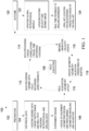
- FIG. 1 illustrates an example workflow 100 for a real-time seismic-while-drilling (SWD) system and process.
- the real-time SWD system provides real-time insight and information to drilling and geo-steering personnel to be able to make informed decisions regarding ongoing drilling programs and steering directions.
- the illustrated workflow 100 includes a preparation process 102, an execution process 108, and an outcome process 120.
- the preparation stage 102 precedes the field execution stage 108 to ensure quality of collected data and ensure smooth execution.
- the execution stage 108 happens in real-time at the field where data is collected, processed, and imaged iteratively while drilling operations are occurring.
- the outcome of this workflow 100 is a real-time feedback 124 to drilling engineers about the drill-bit location, predicting ahead of the drill-bit and more.
- the execution stage 108 includes the following substeps of the workflow 100, including a field acquisition step 110, a data recording step 112, a data processing step 114, and imaging step 116, and a geometry update step 118.
- a geometry layout is determined.
- seismic data is recorded, as well as direct and indirect pilot recording.
- the recorded data is processed, such as by cross-correlation, travel-time difference processing (of acoustic waves), and stacking.
- imaging step 116 migration and velocity update are performed.
- the determined geometry for example, of the relationship between passive acoustic source and acoustic sensors
- a computing system such as an acoustic energy processing system may implement all or parts of execution stage 108.
- the outcome stage 120 includes two sub-stages.
- global petrophysical models generated by the workflow 100 are updated in sub-stage 122.
- This sub-stage 122 can include updating existing velocity and seismic images.
- real-time feedback (for example, concerning the drill bit location) is provided to the drilling engineers for geo-steering.
- a predicted path ahead of the drill bit is provided to the drilling engineers.
- historical data 104 and experimental design data 106 may be looked at to define, for example, the target drilling depth ranges where seismic data are to be recorded while the SWD system operates.
- historical data 102 may include existing regional seismic data, a planned well path, historic drilling information about nearby wells (near the planned well path), and regional petrophysical data.
- Existing regional seismic data can provide images of the subsurface formations or layers to be drilled. This data usually comes in a three-dimensional (3D) volumetric form covering a certain surface area and penetrating to a certain depth into earth. The limits of such data may be denoted by the surface coordinates and depth (X, Y, Z).
- FIG. 2 shows a cross-sectional image 200 that could have a spatial coverage of tens of kilometers (km) and several kilometers in depth, for example 0-4 km.
- Other related data can also be used is the terrain maps collected during the acquired seismic surveys to correctly reconstruct the seismic data in preparation for processing.
- the planned well path narrows down the drill-bit search zone to a single path and what is around the proposed path.
- This path may be used to check which layers from the seismic image the well path will go through during drilling operations with the SWD system.
- Such information can also be used to predict the drilling timeline as different layers of rock take different times to drill through due to their variable hardness and physical properties.
- the rate of penetration (ROP) of the drill-bit into each formation is calculated or estimated as part of the planned well path.
- the cross-sectional image 200 shows a vertical well path 204 from a planned well 202. Also, a narrowed search zone 206 is shown. Drilled well 208 is shown in this figure, which represents a previously drilled well into the sub-surface layers 212, which generates historic drilling information 210.
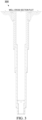
- FIG. 3 is an example plan 300, which shows the design and measurements of well casing pipes that are lowered into the well during drilling to prevent the walls from collapsing into the created void by drilling. These casing pipes also serve as a safety measurement to contain the drilling fluids and protect for sudden pressure increases due to pressurized fluids coming out of drilled formations or rocks.
- FIG. 3 shows a well cross section plot for well casings going down to a vertical depth of 2 km. These casings are usually joined together using shorter pipes (for example, in a casing string).
- These joints may act as amplifiers to sound waves travelling through drilling fluids due to acoustic energy created by a passive downhole acoustic energy source, such as a drill bit of the SWD system or drilling string vibrations.
- a passive downhole acoustic energy source such as a drill bit of the SWD system or drilling string vibrations.
- knowledge of the casing design may add information about the locations of these casing joints and helps in, for instance, either eliminating their effects on recorded signals or in using them as secondary sources of signals providing information from adjacent formations.
- Nearby wells historic drilling information may provide an insight into faced challenges in drilled wells in the same area. It also provides valuable information required to preplan the seismic data acquisition timeline.
- This data 210 can include but is not limited to the following measured data, such as drilling ROP, weight on bit (WOB), drill-bit speed of rotation in cycles per minute, torque used to drill through rocks, etc.
- other descriptive data such as drilling program activities over time can add value as they usually tend to be similar for drilled wells in the same area.
- FIG. 2 the different shades of historic drilling information 210 denote different drilling activities that took place.
- FIGS. 4A-4C show an example of measured drilling information and parameters 400. Other useful information can be the type of equipment as different types of drill-bits emit different amounts of sound waves into the solid rocks being drilled.
- FIGS. 5A-5D show several petrophysical data 500 extracted from the seismic image 502, including density 504, velocity 506, and acoustic impedance 508.
- FIG. 6 shows petrophysical data from a seismic well log 600 that is similar data that are limited to the well location and along its path, which are usually used to calibrate the petrophysical data extracted from the seismic images.
- FIG. 7 illustrates a process 700 for generating an integrated sub-surface model 710 based on the execution of preparation stage 102.
- all or some of the previously described historical data 104 may be used to create an integrated model of the sub-surface layers and their properties, which will be used in later real-time steps to navigate through and guide drilling operations.
- the integrated model can be created using statistical, mathematical, machine learning, data analytics and artificial intelligence operations such as interpolation, kriging, curve fitting, correlations and so on.
- the historical data 104 includes seismic data 702, well path data 704, drilling information data 706, and petrophysical data 708.
- the workflow 100 may also include experiment design sub-step 106.
- experiment design 106 may include choice of equipment. For instance, to achieve the objective of locating and predicting ahead of the drill-bit, a careful choice of equipment has to be made to help ensure that certain objectives are achieved. Such objectives include detecting signals emitted by the drill-bit vibrations and traveling through adjacent formations to the surface. These signals can be detected using surface seismic sensors spread around the monitored well with certain pattern or geometry design.
- Such objective also include detecting signals emitted by the drilling string vibrations into adjacent formations to the surface. Surface sensors can similarly detect these signals. Such objectives also include detecting signals emitted forward by the drill-bit and reflected back to the surface by deeper formations. Surface sensors can similarly detect these signals. Such objectives also include detecting signals traveling through drilling muds or fluids through the borehole up to the surface. Standpipe pressure sensors for example can detect these signals. Such objectives also include detection of the drill-bit signature in the borehole assembly right uphole of the drill-bit. Downhole sensors installed in a saver-sub or drilling string right uphole of the drill bit can detect these signals. Such objectives also include detection of surface noise generated by various sources at the surface where drilling operations are taking place. High sensitivity surface seismic sensors can detect these signals.
- Such objectives also include decent sampling of all detected signals in space and time. This may dictate the number of sensors and their dynamic ranges, which will be used on the surface or in the downhole assembly. Finally, such objectives may also include proper focusing on sub-surface signals. This may dictate the areal coverage of surface sensors.
- certain equipment may be used for recording.
- surface sensor arrays in the order of few thousands with large spatial coverage to detect all signals coming upward from the sub-surface may be used.
- FIG. 8 the shaded patches are an example setting for such sensor arrays.
- surface sensors in the order of few hundreds near noise or vibration sources may be used for the drilling operations to record the noise and enable later steps to eliminate such noise.
- FIG. 8 includes example settings for sensor placement locations.
- surface sensors to record pilot traces near the drilling string entry point to the ground may be used.
- the pilot trace may be recorded at or slightly uphole of the drill bit itself.
- a downhole sensor or sensors near the drill-bit may be used.
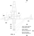
- FIG. 8 illustrates an example implementation of a SWD system 800 that can be used in execution stage 108 to drill a wellbore and, in real-time, collect seismic data from a passive seismic source in the SWD system 800.
- SWD system 800 includes a drilling derrick 802 that operates to drive a rotary table 810 with an electric motor 804 to form wellbore 812 with a drilling bit 816 coupled to a drilling string 814.
- a drilling mud is pumped by a mud pump 806 from a mud tank 808 through the drilling string 814 to, for example, exit the drilling bit 816 and remove cuttings back to the terranean surface on which the derrick 802 sits.
- geophones 818 are mounted on the terranean surface to receive acoustic signals from the drilling bit 816 and other components of the system 800.
- signals include direct signals 820 emitted from casing joints, direct signals 822 emitted from the drilling bit 816, and reflected signals 824 emitted from the drilling bit 816.
- the SWD system 800 includes a number of acoustic sensors/sensor arrays.
- the number of sensors used to acquire seismic data for such experiments can be in the range of few thousands in addition to hundreds of sensors to acquire noise and pilot traces used later for data processing.
- These sensors can be either conventional geophones, high sensitivity geophones or any other special sensors depending on the preferred array arrangements and acquisition requirements.
- the patterns to be used are numerous.
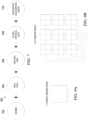
- FIGS. 9A-9B illustrate example implementations of seismic sensor arrays.
- FIG. 9A shows an example array with a single sensing node
- FIG. 9B shows an example with a three by three sensor array, as examples.
- Some of the main parameters to designing these patterns are the number of sensors in each array, the way these sensors are connected (series or parallel), and the special coverage of the array.
- the number of sensors within an array may vary based on the sensors sensitivity to signal and not noise. The greater the number of sensors within an array, the higher the sensitivity of the array to record signals depending on how they are connected. The smaller the areal coverage of an array, the less averaging or smoothing on the recorded signal.
- FIG. 10 illustrates an example implementation of a seismic acquisition geometry 1000.
- thousands of these independent arrays are formed together in a special pattern to form an acquisition geometry.
- each square 1002 is equivalent to one sensor or sensor array and each square 1004 represents an area of an exclusion zone.
- the main parameters used to form an acquisition geometry are: the special sampling, which is the spacing between the centers of sensor arrays; the maximum areal coverage, which is the size of the geometry pattern; and the target depth. These parameters altogether control the signal focusing at a certain target depth.
- a geometry pattern with small areal coverage or small areal extent will only be best used for shallow target depths. The larger the areal coverage extent of a geometry, the deeper depth of target that geometry can be used to focus on. To ensure proper data focusing at the target for a certain target depth twice as much distance of surface areal coverage may be required.
- Multiple of these large scale geometries are designed to record seismic data emitted from different ranges of target depths. These multiple large-scale geometries together form a flexible and adaptable acquisition system.
- the designed sensor array geometries may be validated iteratively using a focal beam approach within the execution stage 108 prior to making a decision to switch to the next geometry in line.
- the following suggested acquisition geometries serve as examples for explanatory purposes of their extent and flexible nature. Additionally, they show how an acquisition geometry is designed taking in consideration the variable depths of targets.
- An actual geometry used with SWD system 800 is not limited to the disclosed three geometry examples in the present disclosure and can be achieved using aerial coverages and different number of geometries based on target depth requirements.
- the initial field experiment (described later) demonstrates the feasibility of such large scale monitoring systems for the purpose of recording seismic wile drilling.
- All disclosed geometries share common design aspects such as being centered around the wellhead location and having a flexible exclusion zone (represented by squares 1004 in FIG. 10 ) that can be sized base on each well's drilling safety requirements. Within this highly active exclusion zone, on the well pad or even on various locations on the drilling rig itself, pilot traces can be recorded to support subsequent data processing and analysis.
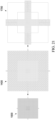
- FIGS. 11A-11D illustrate an example implementation of a symmetric acquisition geometry 1100 centered on the wellhead and targeting shallow depths.
- the geometry 1100 targets shallow depths of around 250 meters (m).
- Geometry 1100 is a hybrid combination of two dimensional (2D) and 3D components centered around the wellhead.
- the first component is a square patch of dense receivers covering an aerial extent of 0.3 square kilometers (km 2 ) to better image the near field energy generated by shallow targets.
- the second component consists of two crossing 2D receiver lines at the wellhead and extending 3 km outward from the center to image the far field energy generated by the shallow targets.
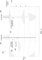
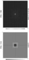
- FIGS. 12A-12B illustrate a geometry validation step through forward modeling showing a vertical cross-sectional image for geometry 1100.
- FIGS. 13A-13B illustrate a geometry validation step through forward modeling showing a horizontal cross-sectional image for geometry 1100.
- a forward modelling study was performed to virtually image a target at depth of 900 feet (ft.) or 274.32 m and at a constant medium velocity of 2000 meters per second (m/s) with a maximum frequency of 200 hertz (Hz).
- the forward modeling result in FIGS. 12A-12B and 13A-13B show concentrated energy plops corresponding to the target at 900 ft. or 274.32 m. This validates the geometry 1100 for imaging shallow targets.
- FIG. 14 illustrates a symmetric acquisition geometry 1400 centered on the wellhead and targeting slightly deeper depths.
- the geometry 1400 targets deeper depths between 250 m to 500 m (in this example).
- Geometry 1400 is also a hybrid combination of 2D and 3D components centered around the wellhead.
- the first component is again a square patch of less dense receivers covering a larger aerial extent of 1.2 km 2 to better image the near field energy generated by slightly deeper targets.
- the second component is the same as in the geometry 1100 consisting of two crossing 2D receiver lines at the wellhead and extending 3 km outward from the center, which are proposed to image the far field energy generated by the slightly deeper targets.
- FIGS. 15A-15B illustrate a geometry validation step through forward modeling showing a vertical cross-sectional image for geometry 1400.
- FIGS. 16A-16B illustrate a geometry validation step through forward modeling showing a horizontal cross-sectional image for geometry 1400.
- a similar forward modelling study was performed to virtually image a target at depth of 1800 ft. or 548.64 m and at a constant medium velocity of 2000 m/s with a maximum frequency of 200 Hz.
- the forward modeling result in FIGS. 15A-15B and 16A-16B show concentrated energy plops corresponding to the target at 1800 ft. or 548.64 m. This validates the geometry 1400 for imaging slightly deeper targets (for example, relative to geometry 1100).
- FIG. 17 illustrates a symmetric acquisition geometry 1700 centered on the wellhead and targeting deeper depths.
- the geometry 1700 targets deeper depths of over 500 m and up to 3000 m.
- Geometry 1700 is also a hybrid combination of 2D components centered around the wellhead.
- the main component of this geometry 1700 consists of two thick 2D lines with multiple (for example, seven in this example) receiver lines each crossing at the wellhead and extending outward by slightly more than 2 km from the center to better image the far field energy generated by deeper targets.
- FIGS. 18A-18B illustrate a geometry validation step through forward modeling showing a vertical cross-sectional image for geometry 1700.
- FIGS. 19A-19B illustrate geometry validation step through forward modeling showing a horizontal cross-sectional image for geometry 1700.
- a similar forward modelling study was performed to virtually image a target at depth of 5000 ft. or 1524 m and at a constant medium velocity of 2000 m/s with a maximum frequency of 200 Hz.
- the forward modeling result in FIG. 18A-18B and 19A-19B show concentrated energy plops corresponding to the target at 5000 ft or 1524 m. This validates the third geometry for imaging deeper targets (for example, relative to geometry 1100).
- FIG. 20 illustrates the example implementation of a SWD system 800 of FIG. 8 with possible locations of extra acoustic sensors.
- SWD system 800 includes the drilling derrick 802 that operates to drive the rotary table 810 with the electric motor 804 to form wellbore 812 with the drilling bit 816 coupled to the drilling string 814.
- the drilling mud is pumped by the mud pump 806 from the mud tank 808 through the drilling string 814 to, for example, exit the drilling bit 816 and remove cuttings back to the terranean surface on which the derrick 802 sits.
- geophones 818 are mounted on the terranean surface to receive acoustic signals from the drilling bit 816 and other components of the system 800.
- signals include direct signals 820 emitted from casing joints, direct signals 822 emitted from the drilling bit 816, and reflected signals 824 emitted from the drilling bit 816.
- the illustrated equipment of FIG. 20 are taken to the field or the drilling rig site to layout the designed acquisition geometries or patterns on the surface around the drilling rig 802.
- These sensors record seismic signals transmitted and reflected from the drilling bit 816 and drilling string 814 travelling through subsurface formations.
- the drilling rig and drilling site are also instrumented with sensors to record pilot signals (drill-bit signature) and surface noises due to drilling activities.
- These recorded signals by surface sensors carry the signatures of the earth formations and the drill bit vibrations.
- These two signatures can be split by cross-correlations or other methods using the recorded pilot signals by surface sensors near the drilling string entry point to the ground.
- the drilling activity noises are decoded out of the recorded signals.
- FIG. 21 illustrates different acquisition geometries 1000, 1400, and 1700 based on different depth ranges.
- the geometry update takes place during drilling down time and goes on repeatedly until a maximum drilling depth is reached.
- the geometry update can be based on drilling depth ranges as explained simplifying the data acquisition process (as in FIG. 21 ) or can be changed adaptively based on signal focusing.
- the use of wireless seismic systems especially those with radio communication may provide flexibility to the sensors deployment enabling execution of such field operation swiftly.
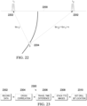
- FIG. 22 illustrates a schematic of travel-time difference with a pair of two receivers (2202) positioned on a terranean surface 2200 and a downhole passive source 2204 (for example, the drilling bit of the SWD system 800).
- a downhole passive source 2204 for example, the drilling bit of the SWD system 800.
- the use of large scale flexible acquisition geometries for seismic while drilling may allow for a more precise determination of drill bit location using the travel-time difference method.
- the main advantage of using a large number of receivers is the unlimited possibility to use multiple combinations of receivers to validate the same goal and increase the signal to noise ratio.
- FIG. 22 shows a basic case involving a pair of surface receivers 2202, ri and r 2 , a drill bit source 2204, S, located at ( x, z ) along the well path, where x is the surface projection of Sand z is the depth of S.
- the energy being emitted by the drill bit source 2204 is received by each receiver 2202 at two different times sharing a common travel-time component and differ by which is the travel-time difference.
- FIG. 23 illustrates an example workflow 2300 for drill bit location using cross-correlation and travel-time difference.
- workflow 2300 includes a first step 2302 in which the seismic data is recorded passively.
- step 2304 the recorded data is then cross-correlated with a reference or pilot traces allowing the energy to be focused on useful signal and not the noise.
- step 2306 the drill bit location is determined using multiple pairs of receivers and references using the imaging condition stated previously. This provides multiple realizations of the drill bit location.
- the travel-time difference images are stacked together. In step 2310, these realizations pin point the drill bit location.
- FIG. 24 illustrates a simple layer earth model 2400.
- the simple layer 2D earth model 2400 is used and a vertical well trajectory is assumed. Further, it is given that seismic is recorded using an acquisition geometry covering the surface at uniformly spaced receivers and centered around the drilling rig. The use of a large number of receivers allows for the use of cross-correlation and travel-time difference for each receiver pairs.
- FIG. 25 illustrates a graph 2500 of recorded seismic while drilling through the model 2400.
- a drill bit recorded signal using all surface receivers would be as shown in the graph 2500 of FIG. 25 , which shows recorded seismic data (from the drilling bit as the passive source) at distances away from the drilling rig (on the x-axis) in time (on the y-axis).
- FIG. 26 illustrates a graph 2600 of cross-correlating using a reference at a receiver, r 1 (as shown in the schematic of FIG. 22 ).
- FIG. 27 illustrates a graph 2700 of cross-correlating using a reference at a receiver, r 2 (as shown in the schematic of FIG. 22 ).
- a reference signal is used for the cross-correlation process resulting in many cross-correlated signals.
- FIG. 28 illustrates a graph 2800 of travel-time difference imaging after cross-correlation using reference at a receiver, r 1 .
- FIG. 29 illustrates a graph 2900 of travel-time difference imaging after cross-correlation using reference at a receiver, r 2 .
- FIG. 30 illustrates a graph 3000 of stacked images revealing the drill bit location. These cross-correlated signals are then used to image the drill bit location using the travel-time difference method for each receiver pair.
- these images still contain imaging artifacts.
- the resulting images are then stacked together to generate a more defined image of the drill bit location by eliminating the imaging artifacts.
- the process of locating the drill bit would be inaccurate and nearly impossible using cross-correlation and travel-time difference.
- the drill bit location was determined in the vertical section 2D plain because of assuming receivers on a 2D line at the surface.
- the use of 3D acquisition geometries extends the possibility of locating the drill bit in three dimensions.
- the use of a large number of receivers allows for imaging and prediction ahead of the drill bit.
- a large number of receivers also allows for better sampling and recording of different seismic waves.
- a new type of body wave can now be recorded while drilling. These body waves are usually generated by tube wave in the wellbore which originate by drill string movements in the wellbore. Such body waves are revealed using conventional passive seismic imaging methods from the low signal-to-noise ratio (S/N) field data.
- S/N signal-to-noise ratio
- VSPs reverse vertical seismic profiles
- an active seismic source is used to generate seismic signals at different locations on the surface while a group of receivers are lowered into the wellbore at different depth levels to record seismic reflections around the wellbore.
- a reverse VSP would use the drill bit as a passive source and the surface receivers as detectors.
- the number of receivers suggested in SWD recording outnumbers the number of receivers in a conventional VSP which does not exceed a 100 receivers at a time. This allows for better recording and detection of seismic signals in noisy environments.
- VSP-WD VSP while drilling
- SWD incorporates seismic techniques while a drill string is lowered in to the borehole, during effective drilling, during maneuvers, and while connecting drill pipes.
- SWD techniques There are two SWD techniques. The first is drill-bit SWD, which records seismic noise generated by the drill bit under effective drilling on the surface seismic sensors.
- VSP-WD which records seismic signals generated by a surface seismic source and seismic receivers inside the borehole. In both techniques, the number of receivers is limited to maximum of 100 receivers and active sources are used on the surface. This in turn results in data recorded at a lower signal to noise ratios and in additional time delays to drilling operations due to the intervening natures of these technologies.
- the present disclosure describes a SWD system in which a large number of receivers (for example, much greater than 100) with limitless geometry setting options without the use of active seismic sources and without interrupting the drilling operations is implemented.
- the concept is demonstrated using a SWD field experiment using a fixed array geometry (for example, as shown in FIG. 17 ) consisting of a thousand receiver points with generally circular shape, in an example implementation.
- the well location is 2.6 km away from the center of the receivers spread.
- the roller bit is considered to be a good passive source for SWD since it is naturally noisy when crushing rocks.
- PDC polycrystalline diamond cutter
- I x ⁇ t u 2 x t
- I ( x ) is the imaging condition at a receiver position ( x )
- u ( x, t ) is the receiver wavefield reconstructed by the formula:
- u x t F ⁇ 1 ⁇ x r D x r ⁇ G ⁇ x r x ⁇
- D(x r , ⁇ ) is the recorded data at the receiver position, x r , after Fourier transform, *, is the complex conjugate
- G(x r , x, ⁇ ) is the frequency-domain Green's Function.
- Green's function can be approximated using a finite-difference or other numerical method to solve the wave equation, for example, the ray
- the reconstructed wavefield is calculated using Eq. (3), making it easier to observe seismic waves coming from the underground sources.
- Eq. (3) After locating the source using Eq. (2), the position of the located source is shallower than the true drill bit depth. However, the locations of the sources are consistent with where velocity contrast is the greatest.
- the received body waves come from secondary sources, which are converted from tube waves in the wellbore. Wave mode conversion happens at locations where large velocity contrasts exit or at some discontinues or density anomalies in casing or wellbore formation (for example, perforations, drill string locks, packers).
- tube waves in the wellbore are related to the movement of drill strings, vibration of the drill bit, and other drilling activities.
- the time series, u(x s , t) can be determined and a time-frequency transformation can be applied on the time series. Once this is compared with the drilling activities, it is determined that the time series is consistent with the drilling activities. From the analysis of reconstructed wavefields, source imaging and time series at the source location, it can be concluded that the recorded seismic waves, mainly body waves generated by tube waves, appear to be useful for SWD.
- the focal beam approach can be used.
- This method utilizes migration as the double focusing process where source and receiver fields can be focused separately for a given velocity model. In turn, this reveals the required amplitude accuracy, offset and azimuth coverage and spatial resolution of a specific field geometry.
- This double focusing approach can be done separately for each specific frequency and at each target diffraction point at a given location.
- the same velocity model as is used in depth for the drill bit imaging, and the target point is assumed as the projection of the well head to the target horizon or target depth.
- the source is always a single point associated to the drill bit location and the receiver arrays are on a fixed layout that is subject to this analysis prior to being modified for different target depths. The results of such analysis obtained in real time allow to evaluate current seismic geometry in terms of resolution and amplitude coverage and propose a new acquisition geometry based on changing source depth.
- FIGS. 31 illustrates a graph 3100 of a field test acquisition geometry 3108 and well location 3106.
- an initial field experiment was conducted to record passively seismic while drilling using a fixed geometry consisting of a thousand receiver points with generally circular shape as shown in FIG. 31 .
- the well location is 2.6 kilometers away from the center of the receivers in the particular geometry.
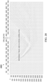
- FIG. 32 illustrates a graph 3200 of raw recorded passive seismic data without any pre-processing applied for the field experiment.
- Graph 3200 includes an x-axis that describes a trace of the raw recorded data and a y-axis that describes time (in seconds) of the raw data.
- the graph 3200 of FIG. 32 shows 12 seconds of raw recorded passive seismic data without any pre-processing applied.
- FIG. 33 illustrates graphs (a, b, and c) of reconstructed wavefields at different times from the raw recorded data of FIG. 33 .
- FIG. 33 three different time snapshots of seismic waves recorded using the field passive seismic setup in FIG. 32 are shown in portions (a), (b), and (c).
- portion (a) shows the wavefield at a time (T);
- portion (b) shows the wavefield at T+0.04 seconds;
- portion (c) shows the wavefield at T+0.08 seconds. From these three reconstructed wavefield snapshots, it can be inferred that the seismic waves propagate from the wellbore to the seismic sensors on the surface.
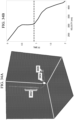
- FIGS. 34A-34B illustrate graphs of an image of a secondary energy source and location of drill bit and a stacking velocity curve.
- FIG. 34A shows an image of a secondary energy source and location of drill bit.
- dots 3402 denote the image around the secondary source
- the dot 3404 denotes the true location of the drill bit
- the dots 3406 denote the well path.
- FIG. 34A shows a stacking velocity curve.
- the horizontal dotted line denotes the pseudo-depth (time) position of the secondary energy source.
- FIG. 35 illustrates graphs of time-frequency analysis of the recorded and processed passive seismic data.
- a time frequency analysis was performed on the recorded passive data.
- the data spans a recording period of three hours and shows excellent correlation between the time-frequency responses and the drilling activities.
- seismic logging while drilling techniques can be used to extract time series at the source location and predict the rock properties in real time by analyzing the correction between the time series and rock properties.
- a seismic logging while drilling workflow can include the following sequence (in the described order or another order). First, a move-out correction is applied to the observed data, for example, by applying a source-receiver distance dependent time shift to each trace. Second, the corrected (or time-shifted) traces can be stacked into a single trace.
- amplitude values of all traces at each time step can be summed together and normalized to provide one supertrace.
- a time-frequency analysis method (such as short-time Fourier transform) can be applied to the stacked trace. Application of the time-frequency analysis method can result in decomposing the time series within each short-time window into different frequency components.
- rock properties can be predicted from the time-frequency spectrum, for example, by applying machine learning techniques such as a neural network analysis. Primary components needed for predicting the propertied can include data obtained earlier in similar conditions.
- information that includes the predicted knowledge of the geological formation around and ahead of the drill bit for example, rock hardness, pore pressure, and fractures
- Adjustments made to drilling programs can result in optimizations related to drilling time and costs.
- the apparatus can be implemented in a computer program product tangibly embodied in an information carrier, for example, in a machine-readable storage device for execution by a programmable processor; and method steps can be performed by a programmable processor executing a program of instructions to perform functions of the described implementations by operating on input data and generating output.
- the described features can be implemented in one or more computer programs that are executable on a programmable system including at least one programmable processor coupled to receive data and instructions from, and to transmit data and instructions to, a data storage system, at least one input device, and at least one output device.
- a computer program is a set of instructions that can be used, directly or indirectly, in a computer to perform a certain activity or bring about a certain result.
- a computer program can be written in any form of programming language, including compiled or interpreted languages, and it can be deployed in any form, including as a stand-alone program or as a module, component, subroutine, or other unit suitable for use in a computing environment.
- Suitable processors for the execution of a program of instructions include, by way of example, both general and special purpose microprocessors, and the sole processor or one of multiple processors of any kind of computer.
- a processor will receive instructions and data from a read-only memory or a random access memory or both.
- the essential elements of a computer are a processor for executing instructions and one or more memories for storing instructions and data.
- a computer will also include, or be operatively coupled to communicate with, one or more mass storage devices for storing data files; such devices include magnetic disks, such as internal hard disks and removable disks; magneto-optical disks; and optical disks.
- Storage devices suitable for tangibly embodying computer program instructions and data include all forms of non-volatile memory, including by way of example semiconductor memory devices, such as erasable programmable read-only memory (EPROM), electrically erasable programmable read-only memory (EEPROM), solid state drives (SSDs), and flash memory devices; magnetic disks such as internal hard disks and removable disks; magneto-optical disks; and CD-ROM and DVD-ROM disks.
- EPROM erasable programmable read-only memory
- EEPROM electrically erasable programmable read-only memory
- SSDs solid state drives
- flash memory devices such as erasable programmable read-only memory (EPROM), electrically erasable programmable read-only memory (EEPROM), solid state drives (SSDs), and flash memory devices
- magnetic disks such as internal hard disks and removable disks
- magneto-optical disks and CD-ROM and DVD-ROM disks.
- the processor and the memory can be supplemented by,
- the features can be implemented on a computer having a display device such as a CRT (cathode ray tube) or LCD (liquid crystal display) or LED (light-emitting diode) monitor for displaying information to the user and a keyboard and a pointing device such as a mouse or a trackball by which the user can provide input to the computer. Additionally, such activities can be implemented via touchscreen flat-panel displays and other appropriate mechanisms.
- a display device such as a CRT (cathode ray tube) or LCD (liquid crystal display) or LED (light-emitting diode) monitor for displaying information to the user and a keyboard and a pointing device such as a mouse or a trackball by which the user can provide input to the computer.
- a keyboard and a pointing device such as a mouse or a trackball by which the user can provide input to the computer.
- the features can be implemented in a control system that includes a back-end component, such as a data server, or that includes a middleware component, such as an application server or an Internet server, or that includes a front-end component, such as a client computer having a graphical user interface or an Internet browser, or any combination of them.
- the components of the system can be connected by any form or medium of digital data communication such as a communication network. Examples of communication networks include a local area network (“LAN”), a wide area network (“WAN”), peer-to-peer networks (having ad-hoc or static members), grid computing infrastructures, and the Internet.
- LAN local area network
- WAN wide area network
- peer-to-peer networks having ad-hoc or static members
- grid computing infrastructures and the Internet.
Landscapes
- Physics & Mathematics (AREA)
- Life Sciences & Earth Sciences (AREA)
- Engineering & Computer Science (AREA)
- Geology (AREA)
- General Life Sciences & Earth Sciences (AREA)
- Environmental & Geological Engineering (AREA)
- Remote Sensing (AREA)
- Acoustics & Sound (AREA)
- Geophysics (AREA)
- General Physics & Mathematics (AREA)
- Mining & Mineral Resources (AREA)
- Fluid Mechanics (AREA)
- Geochemistry & Mineralogy (AREA)
- Geophysics And Detection Of Objects (AREA)
- Earth Drilling (AREA)
Claims (14)
- Verfahren zum Bohren eines Bohrlochs (812), wobei das Verfahren umfasst:
Betreiben eines Systems (800) zur seismischen Messung während des Bohrens, SWD, um die Bildung eines Bohrlochs (812) von einer Erdoberfläche in Richtung einer unterirdischen Zone in einer bestimmten Tiefe unter der Erdoberfläche einzuleiten, wobei das SWD-System eine passive Schallenergiequelle umfasst, die mindestens einen Abschnitt eines Bohrstrangs (814) und eine Mehrzahl von Sätzen von Schallenergieempfängern (818) umfasst, die an der Erdoberfläche positioniert ist, wobei die Mehrzahl von Sätzen von Schallempfängern umfasst:einen ersten Satz von Schallenergieempfängern, der eine erste Erfassungsgeometrie (1000) auf der Erdoberfläche bildet, die auf einem Bohrlochkopf des Bohrlochs (812) zentriert ist und einen ersten räumlichen Bereich auf der Erdoberfläche abdeckt,einen zweiten Satz von Schallenergieempfängern, der eine zweite Erfassungsgeometrie (1400) auf der Erdoberfläche bildet, die auf einem Bohrlochkopf des Bohrlochs zentriert ist und einen zweiten räumlichen Bereich auf der Erdoberfläche abdeckt, der größer als der erste räumliche Bereich ist, undeinen dritten Satz von Schallenergieempfängern, der eine dritte Erfassungsgeometrie (1700) auf der Erdoberfläche bildet, die sich von der ersten und der zweiten Erfassungsgeometrie unterscheidet, wobei die dritte Erfassungsgeometrie zwei dicke 2D-Linien mit mehreren Empfängerlinien umfasst, die sich jeweils am Bohrlochkopf des Bohrlochs (812) kreuzen und nach außen erstrecken;Aufzeichnen von Schallsignalen, die von der passiven Schallenergiequelle erzeugt werden, mit der Mehrzahl von Sätzen von Schallenergieempfängern (818) während der Bildung des Bohrlochs, wobei das Aufzeichnen umfasst:Aufzeichnen, mit dem ersten Satz von Schallenergieempfängern, eines ersten Satzes von Schallsignalen, der von der passiven Schallenergiequelle erzeugt wird, wenn sie zwischen der Erdoberfläche und einer ersten Tiefe ist,Aufzeichnen, mit dem ersten Satz von Schallenergieempfängern, eines zweiten Satzes von Schallsignalen, der von der passiven Schallenergiequelle erzeugt wird, wenn sie zwischen der ersten Tiefe und einer zweiten Tiefe ist, die tiefer als die erste Tiefe ist, undAufzeichnen, mit dem dritten Satz von Schallenergieempfängern, eines dritten Satzes von Schallsignalen, der von der passiven Schallenergiequelle erzeugt wird, wenn sie zwischen der zweiten Tiefe und einer dritten Tiefe ist, die tiefer als die zweite Tiefe ist;Verarbeiten der aufgezeichneten Schallsignale, um eine unterirdische Position der passiven Schallenergiequelle vorherzusagen; undGeosteuern der passiven Schallenergiequelle mit dem SWD-System (800) in Richtung der bestimmten Tiefe unter der Erdoberfläche basierend auf der vorhergesagten unterirdischen Position des passiven Energiequelle. - Verfahren nach Anspruch 1, wobei die passive Schallenergiequelle einen Bohrmeißel (816) des SWD-Systems umfasst.
- Verfahren nach Anspruch 1, wobei die erste Tiefe in 250 Metern ist, die zweite Tiefe in 500 Metern ist und die dritte Tiefe in 1000 Metern ist.
- Verfahren nach Anspruch 1, wobei die dritte Erfassungsgeometrie (1700) einen dritten räumlichen Bereich auf der Erdoberfläche abdeckt, der größer als der zweite räumliche Bereich ist.
- Verfahren nach Anspruch 1, wobei das Verarbeiten der aufgezeichneten Schallsignale zum Vorhersagen einer unterirdischen Position der passiven Schallenergiequelle umfasst:Kreuzkorrelieren (2304) der aufgezeichneten Schallsignale von verschiedenen der Schallempfänger in dem Satz von Schallempfängern;Bestimmen (2306) von Laufzeitdifferenzbildern der aufgezeichneten Schallsignale von der passiven Schallenergiequelle und den verschiedenen Schallempfängern in dem Satz von Schallempfängern; und Stapeln (2308) der Laufzeitdifferenzbilder.
- System (800) zur seismischen Messung während des Bohrens, SWD, umfassend:ein Bohrsystem, das eine Bohranlage, einen Bohrstrang (814) und einen Bohrmeißel (816) umfasst, wobei das Bohrsystem so ausgelegt ist, dass es die Bildung eines Bohrlochs (812) von einer Erdoberfläche in Richtung einer unterirdischen Zone in einer bestimmten Tiefe unter der Erdoberfläche einleitet, wobei das Bohrsystem eine passive Schallenergiequelle umfasst;ein Schallempfängersystem, das eine Mehrzahl von Sätzen von Schallenergieempfängen (818) umfasst, die an der Erdoberfläche positioniert ist, wobei die Mehrzahl von Sätzen von Schallempfängern umfasst:einen ersten Satz von Schallenergieempfängern, der eine erste Erfassungsgeometrie (1000) auf der Erdoberfläche bildet, die auf einem Bohrlochkopf des Bohrlochs zentriert ist und einen ersten räumlichen Bereich auf der Erdoberfläche abdeckt,einen zweiten Satz von Schallenergieempfängern, der eine zweite Erfassungsgeometrie (1400) auf der Erdoberfläche bildet, die auf einem Bohrlochkopf des Bohrlochs zentriert ist und einen zweiten räumlichen Bereich auf der Erdoberfläche abdeckt, der größer als der erste räumliche Bereich ist, undeinen dritten Satz von Schallenergieempfängern, der eine dritte Erfassungsgeometrie (1700) auf der Erdoberfläche bildet, die sich von der ersten und der zweiten Erfassungsgeometrie unterscheidet, wobei die dritte Erfassungsgeometrie zwei dicke 2D-Linien mit mehreren Empfängerlinien umfasst, die sich jeweils am Bohrlochkopf des Bohrlochs kreuzen und nach außen erstrecken;ein Schallenergieverarbeitungssystem, das zum Durchführen von Vorgängen ausgelegt ist, die umfassen:
Aufzeichnen von Schallsignalen, die von der passiven Schallenergiequelle erzeugt werden, mit der Mehrzahl von Sätzen von Schallenergieempfängern (818) während der Bildung des Bohrlochs, wobei das Aufzeichnen umfasst:Aufzeichnen, mit dem ersten Satz von Schallenergieempfängern, eines ersten Satzes von Schallsignalen, der von der passiven Schallenergiequelle erzeugt wird, wenn sie zwischen der Erdoberfläche und einer ersten Tiefe ist,Aufzeichnen, mit dem ersten Satz von Schallenergieempfängern, eines zweiten Satzes von Schallsignalen, der von der passiven Schallenergiequelle erzeugt wird, wenn sie zwischen der ersten Tiefe und einer zweiten Tiefe ist, die tiefer als die erste Tiefe ist, undAufzeichnen, mit dem dritten Satz von Schallenergieempfängern, eines dritten Satzes von Schallsignalen, der von der passiven Schallenergiequelle erzeugt wird, wenn sie zwischen der zweiten Tiefe und einer dritten Tiefe ist, die tiefer als die zweite Tiefe ist;Verarbeiten der aufgezeichneten Schallsignale, um eine unterirdische Position der passiven Schallenergiequelle vorherzusagen; undSteuern des Bohrsystems zum Geosteuern des Bohrmeißels (816) in Richtung der bestimmten Tiefe unter der Erdoberfläche basierend auf der vorhergesagten unterirdischen Position des passiven Energiequelle. - SWD-System nach Anspruch 6, wobei die passive Schallenergiequelle den Bohrmeißel (816) des Bohrsystems umfasst.
- SWD-System nach Anspruch 6, wobei die erste Tiefe in 250 Metern ist, die zweite Tiefe in 500 Metern ist und die dritte Tiefe in 1000 Metern ist.
- SWD-System nach Anspruch 6, wobei die dritte Erfassungsgeometrie (1700) einen dritten räumlichen Bereich auf der Erdoberfläche abdeckt, der größer als der zweite räumliche Bereich ist.
- SWD-System nach Anspruch 6, wobei der Vorgang des Verarbeitens der aufgezeichneten Schallsignale zum Vorhersagen einer unterirdischen Position der passiven Schallenergiequelle umfasst:Kreuzkorrelieren (2304) der aufgezeichneten Schallsignale von verschiedenen der Schallempfänger in dem Satz von Schallempfängern;Bestimmen (2306) von Laufzeitdifferenzbildern der aufgezeichneten Schallsignale von der passiven Schallenergiequelle und den verschiedenen Schallempfängern in dem Satz von Schallempfängern; und Stapeln (2308) der Laufzeitdifferenzbilder.
- Computerimplementiertes Verfahren (2300) zum Bestimmen der Position eines Bohrmeißels (816), wobei das Verfahren umfasst:
Identifizieren, mit einem oder mehreren Hardwareprozessoren eines Schallenergieverarbeitungssystems, einer Mehrzahl von Schallenergiesignalen, die an einer Mehrzahl von Sätzen von Schallempfängern (818) von einer passiven Schallenergiequelle empfangen wird, die Teil eines Bohrlochbohrsystems ist, wobei die Mehrzahl von Sätzen von Schallempfängern (818) umfasst:einen ersten Satz von Schallenergieempfängern, der eine erste Erfassungsgeometrie (1000) auf der Erdoberfläche bildet, die auf einem Bohrlochkopf des Bohrlochs zentriert ist und einen ersten räumlichen Bereich auf der Erdoberfläche abdeckt,einen zweiten Satz von Schallenergieempfängern, der eine zweite Erfassungsgeometrie (1400) auf der Erdoberfläche bildet, die auf einem Bohrlochkopf des Bohrlochs zentriert ist und einen zweiten räumlichen Bereich auf der Erdoberfläche abdeckt, der größer als der erste räumliche Bereich ist, undeinen dritten Satz von Schallenergieempfängern, der eine dritte Erfassungsgeometrie (1700) auf der Erdoberfläche bildet, die sich von der ersten und der zweiten Erfassungsgeometrie unterscheidet, wobei die dritte Erfassungsgeometrie zwei dicke 2D-Linien mit mehreren Empfängerlinien umfasst, die sich jeweils am Bohrlochkopf des Bohrlochs (812) kreuzen und nach außen erstrecken;Verarbeiten der Mehrzahl von Schallenergiesignalen mit dem oder den mehreren Hardwareprozessoren des Schallenergieverarbeitungssystems, wobei die Mehrzahl von Schallsignalen umfasst:einen ersten Satz von Schallsignalen, der am ersten Satz von Schallenergieempfängern empfangen und von der passiven Schallenergiequelle erzeugt wird, wenn sie zwischen der Erdoberfläche und einer ersten Tiefe ist,einen zweiten Satz von Schallsignalen, der am zweiten Satz von Schallenergieempfängern empfangen und von der passiven Schallenergiequelle erzeugt wird, wenn sie zwischen der ersten Tiefe und einer zweiten Tiefe ist, die tiefer als die erste Tiefe ist, undeinen dritten Satz von Schallsignalen, der am dritten Satz von Schallenergieempfängern empfangen und von der passiven Schallenergiequelle erzeugt wird, wenn sie zwischen der zweiten Tiefe und einer dritten Tiefe ist, die tiefer als die zweite Tiefe ist;Bestimmen (2310) einer Position eines Bohrmeißels (816) des Bohrlochbohrsystems mit dem einem oder den mehreren Hardwareprozessoren des Schallenergieverarbeitungssystems basierend auf der verarbeiteten Mehrzahl von Schallsignalen; undAktualisieren eines Geosteuerungspfads des Bohrmeißels (816) mit dem einem oder den mehreren Hardwareprozessoren des Schallenergieverarbeitungssystems basierend auf der bestimmten Position des Bohrmeißels (816). - Computerimplementiertes Verfahren nach Anspruch 11, wobei die passive Schallenergiequelle mindestens eines von dem Bohrmeißel (816) oder einer oder mehreren Rohrmuffen des Bohrsystems umfasst.
- Computerimplementiertes Verfahren nach Anspruch 11, ferner umfassend:
Validieren der Erfassungsgeometrie jedes Satzes der Mehrzahl von Sätzen von Schallempfängern mit dem einem oder den mehreren Hardwareprozessoren des Schallenergieverarbeitungssystems. - Computerimplementiertes Verfahren nach Anspruch 11, ferner umfassend:Kreuzkorrelieren (2304) der aufgezeichneten Schallsignale von verschiedenen der Schallempfänger in jedem Satz der Mehrzahl von Sätzen von Schallempfängern;Bestimmen (2306) von Laufzeitdifferenzbildern der aufgezeichneten Schallsignale von der passiven Schallenergiequelle und den verschiedenen Schallempfängern in dem Satz von Schallempfängern; und Stapeln (2308) der Laufzeitdifferenzbilder.
Applications Claiming Priority (2)
| Application Number | Priority Date | Filing Date | Title |
|---|---|---|---|
| US16/284,803 US11346972B2 (en) | 2019-02-25 | 2019-02-25 | Acquiring seismic data with seismic-while-drilling (SWD) |
| PCT/US2020/019431 WO2020176384A1 (en) | 2019-02-25 | 2020-02-24 | Acquiring seismic data with seismic-while-drilling (swd) |
Publications (2)
| Publication Number | Publication Date |
|---|---|
| EP3931602A1 EP3931602A1 (de) | 2022-01-05 |
| EP3931602B1 true EP3931602B1 (de) | 2024-08-14 |
Family
ID=70009384
Family Applications (1)
| Application Number | Title | Priority Date | Filing Date |
|---|---|---|---|
| EP20714750.5A Active EP3931602B1 (de) | 2019-02-25 | 2020-02-24 | Erfassung seismischer daten mit seismik beim bohren (seismic-while-drilling) |
Country Status (6)
| Country | Link |
|---|---|
| US (1) | US11346972B2 (de) |
| EP (1) | EP3931602B1 (de) |
| CN (1) | CN113474683B (de) |
| CA (1) | CA3131266A1 (de) |
| SA (1) | SA521430130B1 (de) |
| WO (1) | WO2020176384A1 (de) |
Families Citing this family (12)
| Publication number | Priority date | Publication date | Assignee | Title |
|---|---|---|---|---|
| US12203357B2 (en) * | 2018-10-23 | 2025-01-21 | Halliburton Energy Services, Inc. | Systems and methods for drilling a borehole using depth of cut measurements |
| US11080525B1 (en) * | 2019-06-18 | 2021-08-03 | Euram Geo-Focus Technologies Corporation | Methods of identifying flying objects using digital imaging |
| GB2591098B (en) * | 2020-01-14 | 2022-02-23 | Equinor Energy As | Sub-surface well location determination |
| CN112415576B (zh) * | 2020-10-27 | 2024-04-26 | 中煤科工集团西安研究院有限公司 | 一种walkround随钻实时地质导向技术及装置 |
| US20220207419A1 (en) * | 2020-12-30 | 2022-06-30 | Landmark Graphics Corporation | Predictive engine for tracking select seismic variables and predicting horizons |
| CN114089413B (zh) * | 2021-11-23 | 2022-10-14 | 中国科学院地质与地球物理研究所 | 一种获取随钻地震信号方法 |
| US12189074B2 (en) * | 2021-12-10 | 2025-01-07 | Saudi Arabian Oil Company | Event continuity mapping using seismic frequency analysis |
| CN114384588B (zh) * | 2022-01-13 | 2024-04-12 | 安徽惠洲地质安全研究院股份有限公司 | 一种针对随掘超前探测有效信号的加强方法 |
| US12196906B2 (en) * | 2022-10-14 | 2025-01-14 | Saudi Arabian Oil Company | While drilling single well seismic profiling acquisition system using drill bit seismic data |
| US12461261B2 (en) * | 2022-11-07 | 2025-11-04 | GE Vernova Infrastructure Technology | Tunneling and navigation system including distributed communication and sensing system |
| WO2024107079A1 (ru) * | 2022-11-18 | 2024-05-23 | Общество с ограниченной ответственностью "Три-Лоджик" | Бескабельная система контроля внутрискважинных параметров |
| US12474494B2 (en) * | 2022-11-29 | 2025-11-18 | Saudi Arabian Oil Company | Method to determine a time-depth model |
Citations (1)
| Publication number | Priority date | Publication date | Assignee | Title |
|---|---|---|---|---|
| US4207619A (en) * | 1975-02-24 | 1980-06-10 | Alf Klaveness | Seismic well logging system and method |
Family Cites Families (25)
| Publication number | Priority date | Publication date | Assignee | Title |
|---|---|---|---|---|
| US4474250A (en) | 1982-07-16 | 1984-10-02 | David Dardick | Measuring while drilling |
| US5191557A (en) | 1986-12-30 | 1993-03-02 | Gas Research Institute | Signal processing to enable utilization of a rig reference sensor with a drill bit seismic source |
| US4922362A (en) * | 1988-03-04 | 1990-05-01 | Schlumberger Technology Corporation | Methods for deconvolution of unknown source signatures from unknown waveform data |
| US4993001A (en) | 1988-03-04 | 1991-02-12 | Exxon Production Research Company | Method and apparatus for converting tube waves to body waves for seismic exploration |
| US5012453A (en) * | 1990-04-27 | 1991-04-30 | Katz Lewis J | Inverse vertical seismic profiling while drilling |
| US5109947A (en) | 1991-06-21 | 1992-05-05 | Western Atlas International, Inc. | Distributed seismic energy source |
| US6088294A (en) | 1995-01-12 | 2000-07-11 | Baker Hughes Incorporated | Drilling system with an acoustic measurement-while-driving system for determining parameters of interest and controlling the drilling direction |
| CA2209947C (en) | 1995-01-12 | 1999-06-01 | Baker Hughes Incorporated | A measurement-while-drilling acoustic system employing multiple, segmented transmitters and receivers |
| US6614360B1 (en) | 1995-01-12 | 2003-09-02 | Baker Hughes Incorporated | Measurement-while-drilling acoustic system employing multiple, segmented transmitters and receivers |
| US5678643A (en) | 1995-10-18 | 1997-10-21 | Halliburton Energy Services, Inc. | Acoustic logging while drilling tool to determine bed boundaries |
| US6196350B1 (en) | 1999-10-06 | 2001-03-06 | Tomoseis Corporation | Apparatus and method for attenuating tube waves in a borehole |
| US20050034917A1 (en) | 2003-08-14 | 2005-02-17 | Baker Hughes Incorporated | Apparatus and method for acoustic position logging ahead-of-the-bit |
| US7529151B2 (en) | 2004-08-13 | 2009-05-05 | The Regents Of The University Of California | Tube-wave seismic imaging |
| US20060077757A1 (en) | 2004-10-13 | 2006-04-13 | Dale Cox | Apparatus and method for seismic measurement-while-drilling |
| US7512034B2 (en) * | 2005-09-15 | 2009-03-31 | Schlumberger Technology Corporation | Drill noise seismic data acquisition and processing methods |
| US9638818B2 (en) * | 2009-08-03 | 2017-05-02 | Schlumberger Technology Corporation | Methods and apparatus for improved acoustic data acquisition |
| US9110179B2 (en) * | 2010-11-12 | 2015-08-18 | Chevron U.S.A. Inc. | Integrated system for investigating sub-surface features of a rock formation |
| US20160130938A1 (en) * | 2010-11-30 | 2016-05-12 | Tempress Technologies, Inc. | Seismic while drilling system and methods |
| US9234974B2 (en) | 2011-09-26 | 2016-01-12 | Saudi Arabian Oil Company | Apparatus for evaluating rock properties while drilling using drilling rig-mounted acoustic sensors |
| US8800652B2 (en) * | 2011-10-09 | 2014-08-12 | Saudi Arabian Oil Company | Method for real-time monitoring and transmitting hydraulic fracture seismic events to surface using the pilot hole of the treatment well as the monitoring well |
| WO2013163471A1 (en) * | 2012-04-25 | 2013-10-31 | Kolle Jack J | Low-frequency seismic-while-drilling source |
| EP3004537B8 (de) | 2013-06-06 | 2017-09-27 | Rockseis As | Bohrmethode und vorrichtung |
| US9599750B2 (en) * | 2013-10-14 | 2017-03-21 | Hunt Energy Enterprises L.L.C. | Electroseismic surveying in exploration and production environments |
| EA201992827A1 (ru) * | 2017-06-01 | 2020-04-03 | Сауди Арабиан Ойл Компани | Определение структур в недрах земли |
| CN108150102A (zh) * | 2018-03-06 | 2018-06-12 | 西安石油大学 | 一种井眼定位的声导向系统 |
-
2019
- 2019-02-25 US US16/284,803 patent/US11346972B2/en active Active
-
2020
- 2020-02-24 EP EP20714750.5A patent/EP3931602B1/de active Active
- 2020-02-24 CN CN202080016798.2A patent/CN113474683B/zh active Active
- 2020-02-24 CA CA3131266A patent/CA3131266A1/en active Pending
- 2020-02-24 WO PCT/US2020/019431 patent/WO2020176384A1/en not_active Ceased
-
2021
- 2021-08-23 SA SA521430130A patent/SA521430130B1/ar unknown
Patent Citations (1)
| Publication number | Priority date | Publication date | Assignee | Title |
|---|---|---|---|---|
| US4207619A (en) * | 1975-02-24 | 1980-06-10 | Alf Klaveness | Seismic well logging system and method |
Also Published As
| Publication number | Publication date |
|---|---|
| US20200271809A1 (en) | 2020-08-27 |
| US11346972B2 (en) | 2022-05-31 |
| CN113474683B (zh) | 2025-03-25 |
| CN113474683A (zh) | 2021-10-01 |
| WO2020176384A1 (en) | 2020-09-03 |
| SA521430130B1 (ar) | 2023-06-15 |
| EP3931602A1 (de) | 2022-01-05 |
| CA3131266A1 (en) | 2020-09-03 |
Similar Documents
| Publication | Publication Date | Title |
|---|---|---|
| EP3931602B1 (de) | Erfassung seismischer daten mit seismik beim bohren (seismic-while-drilling) | |
| US11525936B2 (en) | Through casing formation slowness evaluation with a sonic logging tool | |
| US9075158B2 (en) | Using a drill bit as a seismic source for SET velocity analysis | |
| US9194967B2 (en) | Tomographic imaging of fracture-fault permeability zones during drilling operations | |
| US9081110B2 (en) | Devices, systems and methods for low frequency seismic borehole investigations | |
| CN103649781B (zh) | 方位角脆性测井系统和方法 | |
| US20060077757A1 (en) | Apparatus and method for seismic measurement-while-drilling | |
| US20210372258A1 (en) | Guiding drilling operations using a subsurface model based on full waveform inversion of seismic-while-drilling data | |
| US20050034917A1 (en) | Apparatus and method for acoustic position logging ahead-of-the-bit | |
| EP3500727B1 (de) | Bohrlochbildgebung mithilfe von amplituden von gebrochenen akustikwellen | |
| US10120093B2 (en) | Methods for in-situ borehole seismic surveys using downhole sources | |
| WO2015061305A1 (en) | Acoustic wave imaging of formations | |
| US10041343B2 (en) | Micro-sonic density imaging while drilling systems and methods | |
| Zhou et al. | Seeing coal‐seam top ahead of the drill bit through seismic‐while‐drilling | |
| US12000730B2 (en) | System and method for monitoring subsurface steam chamber development using fiber optic cables | |
| WO2014183187A1 (en) | Method and apparatus for downhole wellbore placement | |
| US20250075614A1 (en) | Tubing eccentricity evaluation using acoustic signals | |
| US20130094325A1 (en) | Look-ahead seismic while drilling | |
| US20250271585A1 (en) | Drill bit source focusing | |
| Cuvi et al. | First Deployment of High-Definition Ultra-Deep Azimuthal Resistivity Technology in Ecuador: A Step Change in Horizontal Well Placement in the Oriente Basin | |
| Khaled et al. | Seismic-while-drilling in Kuwait results and applications | |
| Wilson | Hybrid Microseismic and Microdeformation Monitoring of a Coal-Seam-Gas Well | |
| Bouziza et al. | Contribution to the use of SWD technology: Simulation Study of a Comparison between VSP and drill bit stick-slip vibration |
Legal Events
| Date | Code | Title | Description |
|---|---|---|---|
| STAA | Information on the status of an ep patent application or granted ep patent |
Free format text: STATUS: UNKNOWN |
|
| STAA | Information on the status of an ep patent application or granted ep patent |
Free format text: STATUS: THE INTERNATIONAL PUBLICATION HAS BEEN MADE |
|
| PUAI | Public reference made under article 153(3) epc to a published international application that has entered the european phase |
Free format text: ORIGINAL CODE: 0009012 |
|
| STAA | Information on the status of an ep patent application or granted ep patent |
Free format text: STATUS: REQUEST FOR EXAMINATION WAS MADE |
|
| 17P | Request for examination filed |
Effective date: 20210906 |
|
| AK | Designated contracting states |
Kind code of ref document: A1 Designated state(s): AL AT BE BG CH CY CZ DE DK EE ES FI FR GB GR HR HU IE IS IT LI LT LU LV MC MK MT NL NO PL PT RO RS SE SI SK SM TR |
|
| DAV | Request for validation of the european patent (deleted) | ||
| DAX | Request for extension of the european patent (deleted) | ||
| STAA | Information on the status of an ep patent application or granted ep patent |
Free format text: STATUS: EXAMINATION IS IN PROGRESS |
|
| 17Q | First examination report despatched |
Effective date: 20221124 |
|
| P01 | Opt-out of the competence of the unified patent court (upc) registered |
Effective date: 20230528 |
|
| GRAP | Despatch of communication of intention to grant a patent |
Free format text: ORIGINAL CODE: EPIDOSNIGR1 |
|
| STAA | Information on the status of an ep patent application or granted ep patent |
Free format text: STATUS: GRANT OF PATENT IS INTENDED |
|
| INTG | Intention to grant announced |
Effective date: 20231113 |
|
| GRAJ | Information related to disapproval of communication of intention to grant by the applicant or resumption of examination proceedings by the epo deleted |
Free format text: ORIGINAL CODE: EPIDOSDIGR1 |
|
| STAA | Information on the status of an ep patent application or granted ep patent |
Free format text: STATUS: EXAMINATION IS IN PROGRESS |
|
| GRAP | Despatch of communication of intention to grant a patent |
Free format text: ORIGINAL CODE: EPIDOSNIGR1 |
|
| STAA | Information on the status of an ep patent application or granted ep patent |
Free format text: STATUS: GRANT OF PATENT IS INTENDED |
|
| INTC | Intention to grant announced (deleted) | ||
| INTG | Intention to grant announced |
Effective date: 20240405 |
|
| GRAS | Grant fee paid |
Free format text: ORIGINAL CODE: EPIDOSNIGR3 |
|
| GRAA | (expected) grant |
Free format text: ORIGINAL CODE: 0009210 |
|
| STAA | Information on the status of an ep patent application or granted ep patent |
Free format text: STATUS: THE PATENT HAS BEEN GRANTED |
|
| AK | Designated contracting states |
Kind code of ref document: B1 Designated state(s): AL AT BE BG CH CY CZ DE DK EE ES FI FR GB GR HR HU IE IS IT LI LT LU LV MC MK MT NL NO PL PT RO RS SE SI SK SM TR |
|
| REG | Reference to a national code |
Ref country code: GB Ref legal event code: FG4D |
|
| REG | Reference to a national code |
Ref country code: CH Ref legal event code: EP |
|
| REG | Reference to a national code |
Ref country code: DE Ref legal event code: R096 Ref document number: 602020035716 Country of ref document: DE |
|
| REG | Reference to a national code |
Ref country code: IE Ref legal event code: FG4D |
|
| REG | Reference to a national code |
Ref country code: LT Ref legal event code: MG9D |
|
| REG | Reference to a national code |
Ref country code: NL Ref legal event code: MP Effective date: 20240814 |
|
| REG | Reference to a national code |
Ref country code: AT Ref legal event code: MK05 Ref document number: 1713809 Country of ref document: AT Kind code of ref document: T Effective date: 20240814 |
|
| PG25 | Lapsed in a contracting state [announced via postgrant information from national office to epo] |
Ref country code: NL Free format text: LAPSE BECAUSE OF FAILURE TO SUBMIT A TRANSLATION OF THE DESCRIPTION OR TO PAY THE FEE WITHIN THE PRESCRIBED TIME-LIMIT Effective date: 20240814 Ref country code: PT Free format text: LAPSE BECAUSE OF FAILURE TO SUBMIT A TRANSLATION OF THE DESCRIPTION OR TO PAY THE FEE WITHIN THE PRESCRIBED TIME-LIMIT Effective date: 20241216 Ref country code: FI Free format text: LAPSE BECAUSE OF FAILURE TO SUBMIT A TRANSLATION OF THE DESCRIPTION OR TO PAY THE FEE WITHIN THE PRESCRIBED TIME-LIMIT Effective date: 20240814 Ref country code: PL Free format text: LAPSE BECAUSE OF FAILURE TO SUBMIT A TRANSLATION OF THE DESCRIPTION OR TO PAY THE FEE WITHIN THE PRESCRIBED TIME-LIMIT Effective date: 20240814 Ref country code: GR Free format text: LAPSE BECAUSE OF FAILURE TO SUBMIT A TRANSLATION OF THE DESCRIPTION OR TO PAY THE FEE WITHIN THE PRESCRIBED TIME-LIMIT Effective date: 20241115 |
|
| PG25 | Lapsed in a contracting state [announced via postgrant information from national office to epo] |
Ref country code: BG Free format text: LAPSE BECAUSE OF FAILURE TO SUBMIT A TRANSLATION OF THE DESCRIPTION OR TO PAY THE FEE WITHIN THE PRESCRIBED TIME-LIMIT Effective date: 20240814 |
|
| PG25 | Lapsed in a contracting state [announced via postgrant information from national office to epo] |
Ref country code: LV Free format text: LAPSE BECAUSE OF FAILURE TO SUBMIT A TRANSLATION OF THE DESCRIPTION OR TO PAY THE FEE WITHIN THE PRESCRIBED TIME-LIMIT Effective date: 20240814 |
|
| PG25 | Lapsed in a contracting state [announced via postgrant information from national office to epo] |
Ref country code: IS Free format text: LAPSE BECAUSE OF FAILURE TO SUBMIT A TRANSLATION OF THE DESCRIPTION OR TO PAY THE FEE WITHIN THE PRESCRIBED TIME-LIMIT Effective date: 20241214 Ref country code: AT Free format text: LAPSE BECAUSE OF FAILURE TO SUBMIT A TRANSLATION OF THE DESCRIPTION OR TO PAY THE FEE WITHIN THE PRESCRIBED TIME-LIMIT Effective date: 20240814 |
|
| PG25 | Lapsed in a contracting state [announced via postgrant information from national office to epo] |
Ref country code: HR Free format text: LAPSE BECAUSE OF FAILURE TO SUBMIT A TRANSLATION OF THE DESCRIPTION OR TO PAY THE FEE WITHIN THE PRESCRIBED TIME-LIMIT Effective date: 20240814 |
|
| PG25 | Lapsed in a contracting state [announced via postgrant information from national office to epo] |
Ref country code: RS Free format text: LAPSE BECAUSE OF FAILURE TO SUBMIT A TRANSLATION OF THE DESCRIPTION OR TO PAY THE FEE WITHIN THE PRESCRIBED TIME-LIMIT Effective date: 20241114 Ref country code: ES Free format text: LAPSE BECAUSE OF FAILURE TO SUBMIT A TRANSLATION OF THE DESCRIPTION OR TO PAY THE FEE WITHIN THE PRESCRIBED TIME-LIMIT Effective date: 20240814 |
|
| PG25 | Lapsed in a contracting state [announced via postgrant information from national office to epo] |
Ref country code: RS Free format text: LAPSE BECAUSE OF FAILURE TO SUBMIT A TRANSLATION OF THE DESCRIPTION OR TO PAY THE FEE WITHIN THE PRESCRIBED TIME-LIMIT Effective date: 20241114 Ref country code: PT Free format text: LAPSE BECAUSE OF FAILURE TO SUBMIT A TRANSLATION OF THE DESCRIPTION OR TO PAY THE FEE WITHIN THE PRESCRIBED TIME-LIMIT Effective date: 20241216 Ref country code: PL Free format text: LAPSE BECAUSE OF FAILURE TO SUBMIT A TRANSLATION OF THE DESCRIPTION OR TO PAY THE FEE WITHIN THE PRESCRIBED TIME-LIMIT Effective date: 20240814 Ref country code: NL Free format text: LAPSE BECAUSE OF FAILURE TO SUBMIT A TRANSLATION OF THE DESCRIPTION OR TO PAY THE FEE WITHIN THE PRESCRIBED TIME-LIMIT Effective date: 20240814 Ref country code: LV Free format text: LAPSE BECAUSE OF FAILURE TO SUBMIT A TRANSLATION OF THE DESCRIPTION OR TO PAY THE FEE WITHIN THE PRESCRIBED TIME-LIMIT Effective date: 20240814 Ref country code: IS Free format text: LAPSE BECAUSE OF FAILURE TO SUBMIT A TRANSLATION OF THE DESCRIPTION OR TO PAY THE FEE WITHIN THE PRESCRIBED TIME-LIMIT Effective date: 20241214 Ref country code: HR Free format text: LAPSE BECAUSE OF FAILURE TO SUBMIT A TRANSLATION OF THE DESCRIPTION OR TO PAY THE FEE WITHIN THE PRESCRIBED TIME-LIMIT Effective date: 20240814 Ref country code: GR Free format text: LAPSE BECAUSE OF FAILURE TO SUBMIT A TRANSLATION OF THE DESCRIPTION OR TO PAY THE FEE WITHIN THE PRESCRIBED TIME-LIMIT Effective date: 20241115 Ref country code: FI Free format text: LAPSE BECAUSE OF FAILURE TO SUBMIT A TRANSLATION OF THE DESCRIPTION OR TO PAY THE FEE WITHIN THE PRESCRIBED TIME-LIMIT Effective date: 20240814 Ref country code: ES Free format text: LAPSE BECAUSE OF FAILURE TO SUBMIT A TRANSLATION OF THE DESCRIPTION OR TO PAY THE FEE WITHIN THE PRESCRIBED TIME-LIMIT Effective date: 20240814 Ref country code: BG Free format text: LAPSE BECAUSE OF FAILURE TO SUBMIT A TRANSLATION OF THE DESCRIPTION OR TO PAY THE FEE WITHIN THE PRESCRIBED TIME-LIMIT Effective date: 20240814 Ref country code: AT Free format text: LAPSE BECAUSE OF FAILURE TO SUBMIT A TRANSLATION OF THE DESCRIPTION OR TO PAY THE FEE WITHIN THE PRESCRIBED TIME-LIMIT Effective date: 20240814 |
|
| PG25 | Lapsed in a contracting state [announced via postgrant information from national office to epo] |
Ref country code: SM Free format text: LAPSE BECAUSE OF FAILURE TO SUBMIT A TRANSLATION OF THE DESCRIPTION OR TO PAY THE FEE WITHIN THE PRESCRIBED TIME-LIMIT Effective date: 20240814 Ref country code: DK Free format text: LAPSE BECAUSE OF FAILURE TO SUBMIT A TRANSLATION OF THE DESCRIPTION OR TO PAY THE FEE WITHIN THE PRESCRIBED TIME-LIMIT Effective date: 20240814 Ref country code: RO Free format text: LAPSE BECAUSE OF FAILURE TO SUBMIT A TRANSLATION OF THE DESCRIPTION OR TO PAY THE FEE WITHIN THE PRESCRIBED TIME-LIMIT Effective date: 20240814 |
|
| PG25 | Lapsed in a contracting state [announced via postgrant information from national office to epo] |
Ref country code: EE Free format text: LAPSE BECAUSE OF FAILURE TO SUBMIT A TRANSLATION OF THE DESCRIPTION OR TO PAY THE FEE WITHIN THE PRESCRIBED TIME-LIMIT Effective date: 20240814 |
|
| PG25 | Lapsed in a contracting state [announced via postgrant information from national office to epo] |
Ref country code: CZ Free format text: LAPSE BECAUSE OF FAILURE TO SUBMIT A TRANSLATION OF THE DESCRIPTION OR TO PAY THE FEE WITHIN THE PRESCRIBED TIME-LIMIT Effective date: 20240814 |
|
| PG25 | Lapsed in a contracting state [announced via postgrant information from national office to epo] |
Ref country code: SK Free format text: LAPSE BECAUSE OF FAILURE TO SUBMIT A TRANSLATION OF THE DESCRIPTION OR TO PAY THE FEE WITHIN THE PRESCRIBED TIME-LIMIT Effective date: 20240814 Ref country code: IT Free format text: LAPSE BECAUSE OF FAILURE TO SUBMIT A TRANSLATION OF THE DESCRIPTION OR TO PAY THE FEE WITHIN THE PRESCRIBED TIME-LIMIT Effective date: 20240814 |
|
| REG | Reference to a national code |
Ref country code: DE Ref legal event code: R097 Ref document number: 602020035716 Country of ref document: DE |
|
| PLBE | No opposition filed within time limit |
Free format text: ORIGINAL CODE: 0009261 |
|
| STAA | Information on the status of an ep patent application or granted ep patent |
Free format text: STATUS: NO OPPOSITION FILED WITHIN TIME LIMIT |
|
| 26N | No opposition filed |
Effective date: 20250515 |
|
| REG | Reference to a national code |
Ref country code: DE Ref legal event code: R119 Ref document number: 602020035716 Country of ref document: DE |
|
| PG25 | Lapsed in a contracting state [announced via postgrant information from national office to epo] |
Ref country code: SE Free format text: LAPSE BECAUSE OF FAILURE TO SUBMIT A TRANSLATION OF THE DESCRIPTION OR TO PAY THE FEE WITHIN THE PRESCRIBED TIME-LIMIT Effective date: 20240814 |
|
| PG25 | Lapsed in a contracting state [announced via postgrant information from national office to epo] |
Ref country code: MC Free format text: LAPSE BECAUSE OF FAILURE TO SUBMIT A TRANSLATION OF THE DESCRIPTION OR TO PAY THE FEE WITHIN THE PRESCRIBED TIME-LIMIT Effective date: 20240814 |
|
| REG | Reference to a national code |
Ref country code: CH Ref legal event code: PL |
|
| PG25 | Lapsed in a contracting state [announced via postgrant information from national office to epo] |
Ref country code: LU Free format text: LAPSE BECAUSE OF NON-PAYMENT OF DUE FEES Effective date: 20250224 |
|
| PG25 | Lapsed in a contracting state [announced via postgrant information from national office to epo] |
Ref country code: CH Free format text: LAPSE BECAUSE OF NON-PAYMENT OF DUE FEES Effective date: 20250228 |
|
| REG | Reference to a national code |
Ref country code: BE Ref legal event code: MM Effective date: 20250228 |
|
| PG25 | Lapsed in a contracting state [announced via postgrant information from national office to epo] |
Ref country code: DE Free format text: LAPSE BECAUSE OF NON-PAYMENT OF DUE FEES Effective date: 20250902 |
|
| PG25 | Lapsed in a contracting state [announced via postgrant information from national office to epo] |
Ref country code: FR Free format text: LAPSE BECAUSE OF NON-PAYMENT OF DUE FEES Effective date: 20250228 |
|
| PG25 | Lapsed in a contracting state [announced via postgrant information from national office to epo] |
Ref country code: BE Free format text: LAPSE BECAUSE OF NON-PAYMENT OF DUE FEES Effective date: 20250228 |
|
| PG25 | Lapsed in a contracting state [announced via postgrant information from national office to epo] |
Ref country code: IE Free format text: LAPSE BECAUSE OF NON-PAYMENT OF DUE FEES Effective date: 20250224 |
|
| PGFP | Annual fee paid to national office [announced via postgrant information from national office to epo] |
Ref country code: GB Payment date: 20260106 Year of fee payment: 7 |
|
| PGFP | Annual fee paid to national office [announced via postgrant information from national office to epo] |
Ref country code: NO Payment date: 20260211 Year of fee payment: 7 |