EP3931517B1 - Firearm comprising a system for moving ammunition - Google Patents
Firearm comprising a system for moving ammunition Download PDFInfo
- Publication number
- EP3931517B1 EP3931517B1 EP20713097.2A EP20713097A EP3931517B1 EP 3931517 B1 EP3931517 B1 EP 3931517B1 EP 20713097 A EP20713097 A EP 20713097A EP 3931517 B1 EP3931517 B1 EP 3931517B1
- Authority
- EP
- European Patent Office
- Prior art keywords
- movable assembly
- driven part
- motor
- firearm
- breech ring
- Prior art date
- Legal status (The legal status is an assumption and is not a legal conclusion. Google has not performed a legal analysis and makes no representation as to the accuracy of the status listed.)
- Active
Links
Images




Classifications
-
- F—MECHANICAL ENGINEERING; LIGHTING; HEATING; WEAPONS; BLASTING
- F41—WEAPONS
- F41A—FUNCTIONAL FEATURES OR DETAILS COMMON TO BOTH SMALLARMS AND ORDNANCE, e.g. CANNONS; MOUNTINGS FOR SMALLARMS OR ORDNANCE
- F41A9/00—Feeding or loading of ammunition; Magazines; Guiding means for the extracting of cartridges
- F41A9/01—Feeding of unbelted ammunition
- F41A9/02—Feeding of unbelted ammunition using wheel conveyors, e.g. star-wheel-shaped conveyors
-
- F—MECHANICAL ENGINEERING; LIGHTING; HEATING; WEAPONS; BLASTING
- F41—WEAPONS
- F41A—FUNCTIONAL FEATURES OR DETAILS COMMON TO BOTH SMALLARMS AND ORDNANCE, e.g. CANNONS; MOUNTINGS FOR SMALLARMS OR ORDNANCE
- F41A7/00—Auxiliary mechanisms for bringing the breech-block or bolt or the barrel to the starting position before automatic firing; Drives for externally-powered guns; Remote-controlled gun chargers
- F41A7/08—Drives for externally-powered guns, i.e. drives for moving the breech-block or bolt by an external force during automatic firing
- F41A7/10—Drives for externally-powered guns, i.e. drives for moving the breech-block or bolt by an external force during automatic firing using a rotating cylindrical drum having a camming groove
-
- F—MECHANICAL ENGINEERING; LIGHTING; HEATING; WEAPONS; BLASTING
- F41—WEAPONS
- F41A—FUNCTIONAL FEATURES OR DETAILS COMMON TO BOTH SMALLARMS AND ORDNANCE, e.g. CANNONS; MOUNTINGS FOR SMALLARMS OR ORDNANCE
- F41A9/00—Feeding or loading of ammunition; Magazines; Guiding means for the extracting of cartridges
- F41A9/38—Loading arrangements, i.e. for bringing the ammunition into the firing position
- F41A9/39—Ramming arrangements
- F41A9/42—Rammers separate from breech-block
-
- F—MECHANICAL ENGINEERING; LIGHTING; HEATING; WEAPONS; BLASTING
- F41—WEAPONS
- F41A—FUNCTIONAL FEATURES OR DETAILS COMMON TO BOTH SMALLARMS AND ORDNANCE, e.g. CANNONS; MOUNTINGS FOR SMALLARMS OR ORDNANCE
- F41A9/00—Feeding or loading of ammunition; Magazines; Guiding means for the extracting of cartridges
- F41A9/50—External power or control systems
- F41A9/51—Boosters, i.e. externally-powered motors
Definitions
- the present invention relates to a firearm comprising a system for moving ammunition.
- firearms typically comprise a breech ring for geometrically closing the firing chamber of the firearm when firing occurs.
- the breech ring is configured for receiving at the inlet a piece of ammunition to be fired.
- firearms include a feeding device configured for feeding said piece of ammunition into a position situated between the movable assembly and the breech ring.
- a barrel through which the piece of ammunition is channelled by the breech ring after firing.
- US 8 833 226 B2 discloses a system wherein a combined breech and ammunition drive is provided for a breech of a weapon and/or for introducing ammunition by a feeding star using an external drive, wherein the respective drive is selectively engaged and disengaged.
- a selector drum that interacts with the drives has slots for the selective engagement and disengagement, and elements are guided in the slots, the slot moving component which engage into the drives in a form-fitted and force-closed manner and which can thereby engage and disengage same.
- the component being 3-way jaw clutches for example.
- JP H07 174488 A discloses a firearm comprising a system for moving ammunition; said system comprising a movable assembly configured for pushing a piece of ammunition into a breech ring of said firearm and/or closing said breech ring under control of a motor; a feeding device configured for feeding said piece of ammunition into a position situated between said movable assembly and said breech ring, and comprising a star loader having a rotatable structure provided with radial arms; and a synchronization mechanism co-operating, on one side, with said motor and, on the other side, with said feeding mechanism; said synchronization mechanism allowing for selective transmission of motion, under control of said movable assembly, from said motor to said feeding mechanism, when said movable assembly is in a position away from said breech ring; wherein said synchronization mechanism comprises an intermitter comprising a driven part rotatably integral with a rotary element of said feeding mechanism; and a driving part configured to be rotatably actuated by said motor
- numeral 1 designates as a whole a firearm intended to fire ammunition A.
- firearm 1 is a single-barrel firearm.
- Firearm 1 comprises a moving system 10 configured for moving ammunition A, made in accordance with an exemplary embodiment of the present invention.
- moving system 10 is configured for handling ammunition A from a magazine (not numbered) to a breech ring 2 of firearm 1.
- breech ring 2 is configured for receiving a piece of ammunition A (visible in particular in Figure 4 ), e.g. a thirty-millimeter (30mm) caliber shell, intended to be fired.
- Firearm 1 comprises a barrel 3, through which the piece of ammunition A is intended to be channelled when firing occurs.
- system 10 further comprises a movable assembly 12 controlled by a motor M (e.g. an electric motor of a per se known type).
- movable assembly 12 is configured for pushing the piece of ammunition A into breech ring 2 and closing said breech ring 2, under control of motor M.
- motor M e.g. an electric motor of a per se known type
- the movement of movable assembly 12 between a position away or remote from breech ring 2 ( Figure 2 ) and an approached position of co-operation with said breech ring ( Figure 2a ) is controlled by an actuation device 14 driven by motor M.
- movable assembly 12 acts as a pusher member, for pushing the piece of ammunition A into breech ring 2, and also as a breechblock member, for closing the firing chamber of firearm 1 prior to firing said piece of ammunition A.
- System 10 further comprises a feeding device 16 configured for feeding the piece of ammunition A between movable assembly 12 and breech ring 2.
- feeding device 16 is also configured for discharging the fired shell case, in particular simultaneously with the feeding of a new piece of ammunition.
- the feeding device is a rotary one and comprises a star loader 18. Said star loader 18 has a rotatable structure with a plurality of radial arms 19.
- each radial arm 19 can take, in turn, one piece of ammunition from the respective magazine (see the piece of ammunition designated as A1 in Figures 5 and 6 ) and bring it into a position between movable assembly 12 and breech ring 2, where it is ready for starting the pressing and firing phase.
- adjacent radial arm 19 can discharge any shell case that may be present at the end of the previous firing phase (see the piece of ammunition designated as A2 in Figures 5 and 6 ), moving it sideways away from the position between movable assembly 12 and breech ring 2.
- system 10 includes a synchronization mechanism 20 co-operating with motor M on one side and, on the other side, with feeding device 16.
- Synchronization mechanism 20 selectively allows, under control of movable assembly 12, for controlled transmission of motion from motor M to feeding device 16.
- the engagement between motor M and feeding device 16 is permitted by synchronization mechanism 20 when movable assembly 12 is in a position away from breech ring 2 ( Figure 2a ). In this condition, the piece of ammunition A to be fired can be loaded (while also discharging any shell case), which will then be pushed into breech ring 2.
- synchronization mechanism 20 in operation synchronization mechanism 20 is kept normally disengaged (e.g. by elastic means, as will be described hereinafter), thus preventing the transmission of motion between motor M and feeding device 16. Said synchronization mechanism 20 is engaged, so that motion can be transmitted from motor M to feeding device 16, when the movable assembly is in the position remote from breech ring 2.
- motor M simultaneously co-operates with movable assembly 12 and with synchronization mechanism 20 to rotatably drive them both.
- an appropriately sized transmission e.g. a gear train
- motor M capable of controlling the motion of movable assembly 12 and of feeding device 16.
- Synchronization mechanism 20 comprises an intermitter 22 configured for converting a continuous rotation of motor M into an intermittent rotation of feeding device 16. More in detail, intermitter 22 comprises a driven part rotatably integral with feeding device 16, and a driving part configured to be rotatably actuated by motor M and to co-operate with the driven part in order to transfer an intermittent motion to the driven part.
- the driven part is rotatably integral with a rotary element of feeding device 16 and rotatable about an axis of rotation Y-Y.
- the driving part is rotatably actuated by motor M about an axis of rotation X-X through suitable transmission means (e.g. meshing toothed wheels).
- the driven portion comprises a pair of roller plates 24, and said rotary element is implemented substantially as a shaft 26, whereon said roller plates 24 are mounted.
- roller plates 24 are axially spaced apart and angularly offset.
- the driving part comprises a pair of cams 28 configured to be rotatably actuated about an axis of rotation X-X by motor M, each one of them co-operating with a respective roller plate 24.
- cams 28 are axially spaced apart and the eccentricities of cams 28 are angularly offset.
- Cams 28 rotatably push respective roller plates 24, and associated shaft 26, when movable assembly 12 is in a position away or remote from breech ring 2.
- the intermitter comprises only one roller plate and only one cam co-operating with said roller plate.
- motor M imparts a continuous rotary motion to cams 28 (clockwise when viewing Figure 4 ).
- cams 28 are configured to rotatably actuate roller plates 24, transferring thereto an intermittent rotary motion (counterclockwise when viewing Figure 4 ). More in detail, the eccentric profiles of cams 28 thrustably engage the periphery of roller plates 24 for only a part of the rotary motion of said cams 28.
- movable assembly 12 is configured for mutually moving and bringing closer to each other (through actuation device 14) pair of roller plates 24 and respective cams 28, for the purpose of selectively engage roller plates 24 and cam 28 when movably assembly 12 is in a position away from breech ring 2.
- movable assembly 12 is configured for causing (through actuation device 14) roller plates 24 to translate along the axis of rotation Y-Y of shaft 26 from an idle position (shown in Figures 3 and 5 ) to an active position.
- an idle position shown in Figures 3 and 5
- cams 28 flank and co-operate with roller plates 24.
- the idle position cams 28 are axially offset relative to roller plates 24 and therefore cannot co-operate with said roller plates 24; thus, in said idle position roller plates 24 and cams 28 are mutually unconstrained in rotation.
- feeding device 16 is prevented from loading the piece of ammunition A; this condition prevents any undesired feeding of the piece of ammunition A when movable assembly 12 is co-operating with breech ring 2 during the pressing and firing phase of the firearm.
- the axis of rotation Y-Y of roller plates 24 and of shaft 26 rotatably integral therewith is substantially parallel to the axis of rotation X-X of cams 28.
- roller plates 24 are coupled to shaft 26 by means of a telescopic coupling.
- shaft 26 comprises a first portion 30 (e.g. a first shaft section) rotatably co-operating with feeding device 16.
- Shaft 26 comprises also a second portion 32 (e.g. a second shaft section), whereon roller plates 24 are mounted.
- the second portion 32 is translatably movable and rotatably integral with the first portion 30.
- movable assembly 12 comprises an engagement element, e.g. a protrusion 33, configured for causing roller plates 24 to translate from the idle position to the active position when movable assembly 12 moves into the position remote from breech ring 2.
- engagement element or protrusion 33 abuts against a portion of shaft 26 or directly against roller plates 24, and pushes them along into their active position, preferably against the action of elastic means (of a per se known type and not shown) tending to keep roller plates 24 in the idle position.
- the first portion 30 and the second portion 32 of shaft 26 are kept close to each other by said elastic means, thus tending to maintain roller plates 24 in the idle position; movable assembly 12 acts against the action of said elastic means, moving the first portion 30 and associated roller plates 24 away from the second portion 32 and so into the active position when said movable assembly 12 is in the position remote from breech ring 2.
- movable assembly 12 may be configured for abutting (in particular, with engagement element or protrusion 33) on a striker element, e.g. a flange 35, carried by shaft 26.
- striker element or flange 35 is carried by the first portion 30 of shaft 26, roller plates 24 being translatably and rotatably integral with the first portion 30 of shaft 26.
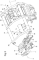
- system 10 comprises also a frame 34 configured for rotatably supporting synchronization mechanism 20, in particular intermitter 22. More in particular, frame 34 rotatably supports shaft 26 (which is rotatably integral with roller plates 24 and feeding device 16) and cams 28.
- frame 34 is implemented substantially as a framework supporting synchronization mechanism 20.
- frame 34 comprises a plurality of plates 36 connected by longitudinal beams 38, in particular at the perimeter of said plates 36.
- each one of plates 36 has a respective aperture 40 configured to be crossed by and rotatably support shaft 26.
- system 10 comprises a linear guide of a per se known type (not shown), whereon movable assembly 12 is configured to slide linearly.
- actuation system 14 comprises also a cylindrical drum 42 configured to be rotatably actuated about a central axis Z-Z by motor M, of a per se known type.
- Cylindrical drum 42 co-operates with movable assembly 12 to control the movement of movable assembly 12 along said linear guide between:
- cylindrical drum 42 is substantially a positive-control multi-revolution cam.
- cylindrical drum 42 defines an external groove 44 in which a pin 46 is coupled, carried by movable assembly 12. Therefore, during the rotation of cylindrical drum 42, the co-operation between groove 44 and pin 46 results in the reciprocating motion of movable assembly 12.
- the driven part and the driving part of the intermitter may be implemented by using elements different from roller plates 24 and cams 28 described in the illustrated embodiment.
Landscapes
- Engineering & Computer Science (AREA)
- General Engineering & Computer Science (AREA)
- Portable Nailing Machines And Staplers (AREA)
- Transmission Devices (AREA)
- Specific Conveyance Elements (AREA)
- Aiming, Guidance, Guns With A Light Source, Armor, Camouflage, And Targets (AREA)
- Glass Compositions (AREA)
Description
- The present invention relates to a firearm comprising a system for moving ammunition.
- In the artillery field, it is known to use firearms that typically comprise a breech ring for geometrically closing the firing chamber of the firearm when firing occurs. In particular, the breech ring is configured for receiving at the inlet a piece of ammunition to be fired. Generally, such firearms include a feeding device configured for feeding said piece of ammunition into a position situated between the movable assembly and the breech ring. There is also a barrel, through which the piece of ammunition is channelled by the breech ring after firing.
- Several system types are known for controlling the moving of ammunition.
-
US 8 833 226 B2 discloses a system wherein a combined breech and ammunition drive is provided for a breech of a weapon and/or for introducing ammunition by a feeding star using an external drive, wherein the respective drive is selectively engaged and disengaged. A selector drum that interacts with the drives has slots for the selective engagement and disengagement, and elements are guided in the slots, the slot moving component which engage into the drives in a form-fitted and force-closed manner and which can thereby engage and disengage same. The component being 3-way jaw clutches for example.JP H07 174488 A - However, prior-art moving systems suffer from a number of drawbacks, which should desirably be overcome.
- It is one object of the present invention to provide an improved firearm comprising a system for moving ammunition, which can overcome the drawbacks of the prior art.
- According to the present invention, this and other objects are achieved through a firearm having an actuation system having the technical features set out in the appended independent claim.
- It is understood that the appended claims are an integral part of the technical teachings provided in the following detailed description of the present invention. In particular, the appended dependent claims define some preferred embodiments of the present invention that include some optional technical features.
- Further features and advantages of the present invention will become apparent in light of the following detailed description, provided merely as a non-limiting example and referring, in particular, to the annexed drawings as summarized below.
-
-
Figure 1 is a perspective view of a firearm comprising a system for moving ammunition made in accordance with an exemplary embodiment of the present invention. -
Figure 2 is a magnified partial side elevation view of the firearm shown inFigure 1 , wherein a part of the moving system is visible. -
Figure 2a is a view similar toFigure 2 , wherein the firearm is in a different operating condition. -
Figure 3 is a magnified perspective view of a part of the moving system shown in the preceding figures. -
Figure 4 is a magnified rear elevation view of the firearm shown inFigure 1 , wherein the above-mentioned moving system is better visible. -
Figure 5 is a perspective view similar toFigure 3 , though it does not show an intermitter supporting frame. Also, this figure provides a better view of the feeding device, e.g. including a star loader, which carries two pieces of ammunition in two different positions. -
Figure 6 is a magnified rear elevation view showing only the feeding device depicted inFigure 5 . - With particular reference to
Figures 1 and2 , numeral 1 designates as a whole a firearm intended to fire ammunition A. By way of example, firearm 1 is a single-barrel firearm. - Firearm 1 comprises a moving
system 10 configured for moving ammunition A, made in accordance with an exemplary embodiment of the present invention. - In particular, moving
system 10 is configured for handling ammunition A from a magazine (not numbered) to abreech ring 2 of firearm 1. - In a per se known manner,
breech ring 2 is configured for receiving a piece of ammunition A (visible in particular inFigure 4 ), e.g. a thirty-millimeter (30mm) caliber shell, intended to be fired. Firearm 1 comprises abarrel 3, through which the piece of ammunition A is intended to be channelled when firing occurs. - With particular reference to
Figure 2 ,system 10 further comprises amovable assembly 12 controlled by a motor M (e.g. an electric motor of a per se known type). In the illustrated embodiment,movable assembly 12 is configured for pushing the piece of ammunition A intobreech ring 2 and closing saidbreech ring 2, under control of motor M. In particular, the movement ofmovable assembly 12 between a position away or remote from breech ring 2 (Figure 2 ) and an approached position of co-operation with said breech ring (Figure 2a ) is controlled by anactuation device 14 driven by motor M. - Preferably, but not necessarily,
movable assembly 12 acts as a pusher member, for pushing the piece of ammunition A intobreech ring 2, and also as a breechblock member, for closing the firing chamber of firearm 1 prior to firing said piece of ammunition A. -
System 10 further comprises afeeding device 16 configured for feeding the piece of ammunition A betweenmovable assembly 12 andbreech ring 2. Preferably,feeding device 16 is also configured for discharging the fired shell case, in particular simultaneously with the feeding of a new piece of ammunition. The feeding device is a rotary one and comprises astar loader 18. Saidstar loader 18 has a rotatable structure with a plurality ofradial arms 19. Particularly, during a rotation movement (counterclockwise when viewingFigure 6 ) ofstar loader 18, eachradial arm 19 can take, in turn, one piece of ammunition from the respective magazine (see the piece of ammunition designated as A1 inFigures 5 and 6 ) and bring it into a position betweenmovable assembly 12 andbreech ring 2, where it is ready for starting the pressing and firing phase. At the same time, during the same rotation movement adjacentradial arm 19 can discharge any shell case that may be present at the end of the previous firing phase (see the piece of ammunition designated as A2 inFigures 5 and 6 ), moving it sideways away from the position betweenmovable assembly 12 andbreech ring 2. - Furthermore,
system 10 includes asynchronization mechanism 20 co-operating with motor M on one side and, on the other side, withfeeding device 16.Synchronization mechanism 20 selectively allows, under control ofmovable assembly 12, for controlled transmission of motion from motor M to feedingdevice 16. The engagement between motor M andfeeding device 16 is permitted bysynchronization mechanism 20 whenmovable assembly 12 is in a position away from breech ring 2 (Figure 2a ). In this condition, the piece of ammunition A to be fired can be loaded (while also discharging any shell case), which will then be pushed intobreech ring 2. - In other terms, in
operation synchronization mechanism 20 is kept normally disengaged (e.g. by elastic means, as will be described hereinafter), thus preventing the transmission of motion between motor M andfeeding device 16. Saidsynchronization mechanism 20 is engaged, so that motion can be transmitted from motor M to feedingdevice 16, when the movable assembly is in the position remote frombreech ring 2. - As schematically shown in
Figure 1 , motor M simultaneously co-operates withmovable assembly 12 and withsynchronization mechanism 20 to rotatably drive them both. In particular, there is an appropriately sized transmission (e.g. a gear train) interposed between motor M and movable assembly 12 (through the associated actuation device 14) andsynchronization mechanism 20. In this manner, there is preferably a single motor M capable of controlling the motion ofmovable assembly 12 and offeeding device 16. -
Synchronization mechanism 20 comprises anintermitter 22 configured for converting a continuous rotation of motor M into an intermittent rotation offeeding device 16. More in detail,intermitter 22 comprises a driven part rotatably integral withfeeding device 16, and a driving part configured to be rotatably actuated by motor M and to co-operate with the driven part in order to transfer an intermittent motion to the driven part. - In particular, the driven part is rotatably integral with a rotary element of
feeding device 16 and rotatable about an axis of rotation Y-Y. On the contrary, the driving part is rotatably actuated by motor M about an axis of rotation X-X through suitable transmission means (e.g. meshing toothed wheels). - In the illustrated embodiment, the driven portion comprises a pair of
roller plates 24, and said rotary element is implemented substantially as ashaft 26, whereon saidroller plates 24 are mounted. For example,roller plates 24 are axially spaced apart and angularly offset. - In the illustrated embodiment, the driving part comprises a pair of
cams 28 configured to be rotatably actuated about an axis of rotation X-X by motor M, each one of them co-operating with arespective roller plate 24. Likeroller plates 24, the cams are axially spaced apart and the eccentricities ofcams 28 are angularly offset. -
Cams 28 rotatably pushrespective roller plates 24, and associatedshaft 26, whenmovable assembly 12 is in a position away or remote frombreech ring 2. In further variant embodiments not illustrated herein, it may be envisaged that the intermitter comprises only one roller plate and only one cam co-operating with said roller plate. - In particular, motor M imparts a continuous rotary motion to cams 28 (clockwise when viewing
Figure 4 ). In turn,cams 28 are configured to rotatablyactuate roller plates 24, transferring thereto an intermittent rotary motion (counterclockwise when viewingFigure 4 ). More in detail, the eccentric profiles ofcams 28 thrustably engage the periphery ofroller plates 24 for only a part of the rotary motion of saidcams 28. - In the illustrated embodiment,
movable assembly 12 is configured for mutually moving and bringing closer to each other (through actuation device 14) pair ofroller plates 24 andrespective cams 28, for the purpose of selectively engageroller plates 24 andcam 28 whenmovably assembly 12 is in a position away frombreech ring 2. - Preferably,
movable assembly 12 is configured for causing (through actuation device 14)roller plates 24 to translate along the axis of rotation Y-Y ofshaft 26 from an idle position (shown inFigures 3 and5 ) to an active position. In the active position,cams 28 flank and co-operate withroller plates 24. In the idle position,cams 28 are axially offset relative toroller plates 24 and therefore cannot co-operate with saidroller plates 24; thus, in said idleposition roller plates 24 andcams 28 are mutually unconstrained in rotation. In this way, in the idleposition feeding device 16 is prevented from loading the piece of ammunition A; this condition prevents any undesired feeding of the piece of ammunition A whenmovable assembly 12 is co-operating withbreech ring 2 during the pressing and firing phase of the firearm. - The axis of rotation Y-Y of
roller plates 24 and ofshaft 26 rotatably integral therewith is substantially parallel to the axis of rotation X-X ofcams 28. - In the illustrated embodiment,
roller plates 24 are coupled toshaft 26 by means of a telescopic coupling. - In the illustrated embodiment,
shaft 26 comprises a first portion 30 (e.g. a first shaft section) rotatably co-operating with feedingdevice 16.Shaft 26 comprises also a second portion 32 (e.g. a second shaft section), whereonroller plates 24 are mounted. Thesecond portion 32 is translatably movable and rotatably integral with thefirst portion 30. - In particular,
movable assembly 12 comprises an engagement element, e.g. aprotrusion 33, configured for causingroller plates 24 to translate from the idle position to the active position whenmovable assembly 12 moves into the position remote frombreech ring 2. For example, when the movement into said remote position occurs, engagement element orprotrusion 33 abuts against a portion ofshaft 26 or directly againstroller plates 24, and pushes them along into their active position, preferably against the action of elastic means (of a per se known type and not shown) tending to keeproller plates 24 in the idle position. - Preferably, the
first portion 30 and thesecond portion 32 ofshaft 26 are kept close to each other by said elastic means, thus tending to maintainroller plates 24 in the idle position;movable assembly 12 acts against the action of said elastic means, moving thefirst portion 30 and associatedroller plates 24 away from thesecond portion 32 and so into the active position when saidmovable assembly 12 is in the position remote frombreech ring 2. - By way of example,
movable assembly 12 may be configured for abutting (in particular, with engagement element or protrusion 33) on a striker element, e.g. aflange 35, carried byshaft 26. In particular, striker element orflange 35 is carried by thefirst portion 30 ofshaft 26,roller plates 24 being translatably and rotatably integral with thefirst portion 30 ofshaft 26. - In the illustrated embodiment,
system 10 comprises also aframe 34 configured for rotatably supportingsynchronization mechanism 20, inparticular intermitter 22. More in particular,frame 34 rotatably supports shaft 26 (which is rotatably integral withroller plates 24 and feeding device 16) andcams 28. - In the illustrated embodiment, with particular reference to
Figure 3 ,frame 34 is implemented substantially as a framework supportingsynchronization mechanism 20. In particular,frame 34 comprises a plurality ofplates 36 connected bylongitudinal beams 38, in particular at the perimeter of saidplates 36. - For example, each one of
plates 36 has arespective aperture 40 configured to be crossed by androtatably support shaft 26. - In the illustrated embodiment,
system 10 comprises a linear guide of a per se known type (not shown), whereonmovable assembly 12 is configured to slide linearly. - In the illustrated embodiment,
actuation system 14 comprises also acylindrical drum 42 configured to be rotatably actuated about a central axis Z-Z by motor M, of a per se known type. -
Cylindrical drum 42 co-operates withmovable assembly 12 to control the movement ofmovable assembly 12 along said linear guide between: - the position away or remote from
breech ring 2, shown inFigure 2 , for the phases of loading the piece of ammunition A and for discharging any shell case prior to pressing the piece of ammunition A towardsbreech ring 2, and - the approached position of co-operation with
breech ring 2, shown inFigure 2a , for the phases of firing the loaded piece of ammunition. - In the illustrated embodiment,
cylindrical drum 42 is substantially a positive-control multi-revolution cam. - The outer surface of
cylindrical drum 42 defines anexternal groove 44 in which apin 46 is coupled, carried bymovable assembly 12. Therefore, during the rotation ofcylindrical drum 42, the co-operation betweengroove 44 andpin 46 results in the reciprocating motion ofmovable assembly 12. - Of course, without prejudice to the principle of the present invention, the forms of embodiment and the implementation details may be extensively varied from those described and illustrated herein merely by way of non-limiting example, without however departing from the scope of the invention as set out in the appended claims.
- By way of non-limiting example, as will be apparent to a person skilled in the art, the driven part and the driving part of the intermitter may be implemented by using elements different from
roller plates 24 andcams 28 described in the illustrated embodiment.
Claims (10)
- Firearm (1) comprising a system (10) for moving ammunition (A); said system comprising:- a movable assembly (12) configured for pushing a piece of ammunition (A) into a breech ring (2) of said firearm (1) and/or closing said breech ring (2), under control of a motor (M) ;- a feeding device (16) configured for feeding said piece of ammunition (A) into a position situated between said movable assembly (12) and said breech ring (2), and comprising a star loader (18) having a rotatable structure provided with radial arms (19); and- a synchronization mechanism (20) co-operating, on one side, with said motor (M) and, on the other side, with said feeding mechanism (16); said synchronization mechanism allowing for selective transmission of motion, under control of said movable assembly (12), from said motor (M) to said feeding mechanism (16), when said movable assembly (12) is in a position away from said breech ring (2);wherein said synchronization mechanism (20) comprises an intermitter (22) comprising:- a driven part (24) rotatably integral with a rotary element (26) of said feeding mechanism (16); and- a driving part (28) configured to be rotatably actuated by said motor (M) and to intermittently transfer said rotation to said driven part (24), when said movable assembly (12) is in a position away from said breech ring (2);wherein said rotary element is implemented substantially as a shaft (26) supporting said radial arms (19) of said star loader (18); andwherein the axis of rotation (Y-Y) of said shaft (26) is parallel to the axis of rotation (X-X) of said driving part (28);characterised in that said movable assembly (12) is configured for moving said driven part (24) and said driving part (28) close to each other, selectively engaging said driven part (24) and said driving part (28) when said movable assembly (12) is in a position away from said breech ring (2) .
- Firearm according to claim 1, wherein said movable assembly (12) is configured for laterally aligning said driven part (24) and said driving part (28).
- Firearm according to claim 2, wherein said movable assembly (12) is configured for moving said driven part (24) along the axis of rotation (Y-Y) of said shaft (26) from an idle position, in which said driven part (24) is axially offset relative to said driven part (24), to an active position, in which said driving part (28) substantially flanks and co-operates with said driven part (24).
- Firearm according to any one of the preceding claims, wherein said driven part (24) is coupled to said shaft (26) via a telescopic coupling.
- Firearm according to claim 4, wherein said shaft (26) comprises:- a first portion (30) rotatably co-operating with said feeding device (16), and- a second portion (32) whereon said driven part (24) is mounted, said second portion (32) being translatably movable and rotatably integral relative to said first portion (30).
- Firearm according to any one of the preceding claims, further comprising a frame (34) configured for rotatably supporting said driven part (24), said shaft (26), and said driving part (28).
- Firearm according to any one of the preceding claims, wherein said driven part comprises at least one roller plate (24) .
- Firearm according to claim 7, wherein said driving part comprises at least one cam (28) configured for rotatably pushing said roller plate (24) when the movable assembly (12) is in a position away from said breech ring (2).
- Firearm according to any one of the preceding claims, wherein said movable assembly (12) is controlled by an actuation device (14) driven by the motor (M).
- Firearm according to claim 9, further comprising a cylindrical drum (42) configured to be rotatably actuated by the motor (44) and co-operating with the movable assembly (12) .
Applications Claiming Priority (2)
| Application Number | Priority Date | Filing Date | Title |
|---|---|---|---|
| IT102019000002647A IT201900002647A1 (en) | 2019-02-25 | 2019-02-25 | SYSTEM FOR HANDLING AMMUNITION FOR A FIREARM. |
| PCT/IB2020/051540 WO2020174361A1 (en) | 2019-02-25 | 2020-02-24 | System for moving ammunition for a firearm |
Publications (2)
| Publication Number | Publication Date |
|---|---|
| EP3931517A1 EP3931517A1 (en) | 2022-01-05 |
| EP3931517B1 true EP3931517B1 (en) | 2023-06-07 |
Family
ID=66641268
Family Applications (1)
| Application Number | Title | Priority Date | Filing Date |
|---|---|---|---|
| EP20713097.2A Active EP3931517B1 (en) | 2019-02-25 | 2020-02-24 | Firearm comprising a system for moving ammunition |
Country Status (9)
| Country | Link |
|---|---|
| US (1) | US11592249B2 (en) |
| EP (1) | EP3931517B1 (en) |
| KR (1) | KR20210145148A (en) |
| CN (1) | CN113646604A (en) |
| BR (1) | BR112021016806A2 (en) |
| CA (1) | CA3128543A1 (en) |
| IT (1) | IT201900002647A1 (en) |
| SG (1) | SG11202109224XA (en) |
| WO (1) | WO2020174361A1 (en) |
Family Cites Families (14)
| Publication number | Priority date | Publication date | Assignee | Title |
|---|---|---|---|---|
| US4131052A (en) * | 1977-07-05 | 1978-12-26 | The United States Of America As Represented By The Secretary Of The Army | Drum cam with anti hang-fire feature |
| US5392685A (en) * | 1983-08-18 | 1995-02-28 | Ares, Inc. | Automatic cannon with carbioid-shaped shell chamber path |
| FR2579743B1 (en) * | 1985-03-26 | 1987-05-15 | France Etat Armement | AUTOMATIC WEAPON WITH EXTERNAL MOTOR |
| JPH07174488A (en) * | 1993-12-16 | 1995-07-14 | Japan Steel Works Ltd:The | Playground drive mechanism |
| JPH07174487A (en) * | 1993-12-20 | 1995-07-14 | Japan Steel Works Ltd:The | Machine gun closing method and device |
| DE102006006961A1 (en) * | 2006-02-14 | 2007-08-23 | Oerlikon Contraves Ag | Ammunition feeder with automatic clutch |
| US7971515B2 (en) * | 2007-12-13 | 2011-07-05 | Garwood Tracy W | Access door for feeder/delinker of a gatling gun |
| DE102008062768B4 (en) * | 2008-12-18 | 2011-06-16 | Rheinmetall Waffe Munition Gmbh | Drum and ammunition drive of a drum weapon |
| ES2438785T3 (en) * | 2009-12-04 | 2014-01-20 | Rheinmetall Waffe Munition Gmbh | Selective cylinder head and / or ammunition operation |
| CN103453798B (en) * | 2012-05-29 | 2016-03-09 | 四川华庆机械有限责任公司 | A kind of firing frequency enclosed ammunition belt takes off chain ammunition feed mechanism |
| WO2015026419A2 (en) * | 2013-06-03 | 2015-02-26 | Profense, Llc | Minigun with improved feeder sprocket and shaft |
| US9702649B1 (en) * | 2014-07-18 | 2017-07-11 | The United States Of America As Represented By The Secretary Of The Army | Reciprocally-cycled weapon |
| US10352638B1 (en) * | 2018-04-23 | 2019-07-16 | Daycraft Weapon Systems, LLC | Gun having multi-drive link feed system and method therefor |
| US10871336B1 (en) * | 2018-10-30 | 2020-12-22 | Travis Johnston | Revolving battery machine gun with electronically controlled drive motors |
-
2019
- 2019-02-25 IT IT102019000002647A patent/IT201900002647A1/en unknown
-
2020
- 2020-02-24 US US17/433,499 patent/US11592249B2/en active Active
- 2020-02-24 CA CA3128543A patent/CA3128543A1/en active Pending
- 2020-02-24 WO PCT/IB2020/051540 patent/WO2020174361A1/en not_active Ceased
- 2020-02-24 CN CN202080025752.7A patent/CN113646604A/en active Pending
- 2020-02-24 KR KR1020217030487A patent/KR20210145148A/en not_active Ceased
- 2020-02-24 SG SG11202109224XA patent/SG11202109224XA/en unknown
- 2020-02-24 BR BR112021016806A patent/BR112021016806A2/en not_active Application Discontinuation
- 2020-02-24 EP EP20713097.2A patent/EP3931517B1/en active Active
Also Published As
| Publication number | Publication date |
|---|---|
| EP3931517A1 (en) | 2022-01-05 |
| IT201900002647A1 (en) | 2020-08-25 |
| WO2020174361A1 (en) | 2020-09-03 |
| KR20210145148A (en) | 2021-12-01 |
| CA3128543A1 (en) | 2020-08-03 |
| SG11202109224XA (en) | 2021-09-29 |
| US20220187038A1 (en) | 2022-06-16 |
| CN113646604A (en) | 2021-11-12 |
| BR112021016806A2 (en) | 2021-11-16 |
| US11592249B2 (en) | 2023-02-28 |
Similar Documents
| Publication | Publication Date | Title |
|---|---|---|
| US10941994B2 (en) | Cased telescoped ammunition firearm with dual feed | |
| US10871336B1 (en) | Revolving battery machine gun with electronically controlled drive motors | |
| KR20110097794A (en) | Preferably a drive device with a quick stop mechanism for weapons with a linear bolt or ammunition feed device | |
| US10139175B1 (en) | Gas operated machine gun | |
| US8833226B2 (en) | Selective breechblock and/or ammunition drive | |
| US9377262B2 (en) | Barrel with cam followers | |
| US11592249B2 (en) | Firearm comprising a system for moving ammunition for a firearm | |
| US4311081A (en) | Dual, two stage shell feeding apparatus for guns | |
| US3380342A (en) | Clearing mechanism for high rate of fire multi-barrel automatic weapon | |
| US6073534A (en) | Transfer mechanism and method for uploading and downloading propellant charges and projectiles | |
| HK40062395A (en) | System for moving ammunition for a firearm | |
| US3296930A (en) | Clutch-lock for externally powered firearm feeding mechanism | |
| US4561340A (en) | Two-barrel revolver-type firearm | |
| US2905056A (en) | Feeder device for the automatic loading of guns | |
| US4450750A (en) | Dual shell feeding apparatus, with shell accumulators, for automatic guns | |
| US3362293A (en) | Round feeding mechanism for automatic guns | |
| RU2603246C1 (en) | Cartridgeless automatic gun with bullet chamber of variable volume | |
| WO1985005442A1 (en) | Multi-barrel machine gun | |
| US5315913A (en) | Gun mechanism for rapidly firing cased telescoped ammunition | |
| EP1216392B1 (en) | Ammunition handling system | |
| US2746357A (en) | Feed mechanism | |
| EP3931520B1 (en) | Breechblock assembly for a firearm and related firearm | |
| WO2020174363A1 (en) | Recoil mass of a firearm and related firearm | |
| US2389943A (en) | Gun charger | |
| US4421008A (en) | Timed round stop for a sprocket fed weapon |
Legal Events
| Date | Code | Title | Description |
|---|---|---|---|
| STAA | Information on the status of an ep patent application or granted ep patent |
Free format text: STATUS: UNKNOWN |
|
| STAA | Information on the status of an ep patent application or granted ep patent |
Free format text: STATUS: THE INTERNATIONAL PUBLICATION HAS BEEN MADE |
|
| PUAI | Public reference made under article 153(3) epc to a published international application that has entered the european phase |
Free format text: ORIGINAL CODE: 0009012 |
|
| STAA | Information on the status of an ep patent application or granted ep patent |
Free format text: STATUS: REQUEST FOR EXAMINATION WAS MADE |
|
| 17P | Request for examination filed |
Effective date: 20210920 |
|
| AK | Designated contracting states |
Kind code of ref document: A1 Designated state(s): AL AT BE BG CH CY CZ DE DK EE ES FI FR GB GR HR HU IE IS IT LI LT LU LV MC MK MT NL NO PL PT RO RS SE SI SK SM TR |
|
| DAV | Request for validation of the european patent (deleted) | ||
| DAX | Request for extension of the european patent (deleted) | ||
| GRAP | Despatch of communication of intention to grant a patent |
Free format text: ORIGINAL CODE: EPIDOSNIGR1 |
|
| STAA | Information on the status of an ep patent application or granted ep patent |
Free format text: STATUS: GRANT OF PATENT IS INTENDED |
|
| INTG | Intention to grant announced |
Effective date: 20220923 |
|
| GRAS | Grant fee paid |
Free format text: ORIGINAL CODE: EPIDOSNIGR3 |
|
| GRAA | (expected) grant |
Free format text: ORIGINAL CODE: 0009210 |
|
| STAA | Information on the status of an ep patent application or granted ep patent |
Free format text: STATUS: THE PATENT HAS BEEN GRANTED |
|
| AK | Designated contracting states |
Kind code of ref document: B1 Designated state(s): AL AT BE BG CH CY CZ DE DK EE ES FI FR GB GR HR HU IE IS IT LI LT LU LV MC MK MT NL NO PL PT RO RS SE SI SK SM TR |
|
| REG | Reference to a national code |
Ref country code: GB Ref legal event code: FG4D |
|
| REG | Reference to a national code |
Ref country code: CH Ref legal event code: EP Ref country code: AT Ref legal event code: REF Ref document number: 1576290 Country of ref document: AT Kind code of ref document: T Effective date: 20230615 |
|
| REG | Reference to a national code |
Ref country code: DE Ref legal event code: R096 Ref document number: 602020011946 Country of ref document: DE |
|
| REG | Reference to a national code |
Ref country code: LT Ref legal event code: MG9D |
|
| REG | Reference to a national code |
Ref country code: NL Ref legal event code: MP Effective date: 20230607 |
|
| PG25 | Lapsed in a contracting state [announced via postgrant information from national office to epo] |
Ref country code: SE Free format text: LAPSE BECAUSE OF FAILURE TO SUBMIT A TRANSLATION OF THE DESCRIPTION OR TO PAY THE FEE WITHIN THE PRESCRIBED TIME-LIMIT Effective date: 20230607 Ref country code: NO Free format text: LAPSE BECAUSE OF FAILURE TO SUBMIT A TRANSLATION OF THE DESCRIPTION OR TO PAY THE FEE WITHIN THE PRESCRIBED TIME-LIMIT Effective date: 20230907 Ref country code: ES Free format text: LAPSE BECAUSE OF FAILURE TO SUBMIT A TRANSLATION OF THE DESCRIPTION OR TO PAY THE FEE WITHIN THE PRESCRIBED TIME-LIMIT Effective date: 20230607 |
|
| REG | Reference to a national code |
Ref country code: AT Ref legal event code: MK05 Ref document number: 1576290 Country of ref document: AT Kind code of ref document: T Effective date: 20230607 |
|
| PG25 | Lapsed in a contracting state [announced via postgrant information from national office to epo] |
Ref country code: RS Free format text: LAPSE BECAUSE OF FAILURE TO SUBMIT A TRANSLATION OF THE DESCRIPTION OR TO PAY THE FEE WITHIN THE PRESCRIBED TIME-LIMIT Effective date: 20230607 Ref country code: NL Free format text: LAPSE BECAUSE OF FAILURE TO SUBMIT A TRANSLATION OF THE DESCRIPTION OR TO PAY THE FEE WITHIN THE PRESCRIBED TIME-LIMIT Effective date: 20230607 Ref country code: LV Free format text: LAPSE BECAUSE OF FAILURE TO SUBMIT A TRANSLATION OF THE DESCRIPTION OR TO PAY THE FEE WITHIN THE PRESCRIBED TIME-LIMIT Effective date: 20230607 Ref country code: LT Free format text: LAPSE BECAUSE OF FAILURE TO SUBMIT A TRANSLATION OF THE DESCRIPTION OR TO PAY THE FEE WITHIN THE PRESCRIBED TIME-LIMIT Effective date: 20230607 Ref country code: HR Free format text: LAPSE BECAUSE OF FAILURE TO SUBMIT A TRANSLATION OF THE DESCRIPTION OR TO PAY THE FEE WITHIN THE PRESCRIBED TIME-LIMIT Effective date: 20230607 Ref country code: GR Free format text: LAPSE BECAUSE OF FAILURE TO SUBMIT A TRANSLATION OF THE DESCRIPTION OR TO PAY THE FEE WITHIN THE PRESCRIBED TIME-LIMIT Effective date: 20230908 |
|
| PG25 | Lapsed in a contracting state [announced via postgrant information from national office to epo] |
Ref country code: FI Free format text: LAPSE BECAUSE OF FAILURE TO SUBMIT A TRANSLATION OF THE DESCRIPTION OR TO PAY THE FEE WITHIN THE PRESCRIBED TIME-LIMIT Effective date: 20230607 |
|
| PG25 | Lapsed in a contracting state [announced via postgrant information from national office to epo] |
Ref country code: SK Free format text: LAPSE BECAUSE OF FAILURE TO SUBMIT A TRANSLATION OF THE DESCRIPTION OR TO PAY THE FEE WITHIN THE PRESCRIBED TIME-LIMIT Effective date: 20230607 |
|
| PG25 | Lapsed in a contracting state [announced via postgrant information from national office to epo] |
Ref country code: IS Free format text: LAPSE BECAUSE OF FAILURE TO SUBMIT A TRANSLATION OF THE DESCRIPTION OR TO PAY THE FEE WITHIN THE PRESCRIBED TIME-LIMIT Effective date: 20231007 |
|
| PG25 | Lapsed in a contracting state [announced via postgrant information from national office to epo] |
Ref country code: SM Free format text: LAPSE BECAUSE OF FAILURE TO SUBMIT A TRANSLATION OF THE DESCRIPTION OR TO PAY THE FEE WITHIN THE PRESCRIBED TIME-LIMIT Effective date: 20230607 Ref country code: SK Free format text: LAPSE BECAUSE OF FAILURE TO SUBMIT A TRANSLATION OF THE DESCRIPTION OR TO PAY THE FEE WITHIN THE PRESCRIBED TIME-LIMIT Effective date: 20230607 Ref country code: RO Free format text: LAPSE BECAUSE OF FAILURE TO SUBMIT A TRANSLATION OF THE DESCRIPTION OR TO PAY THE FEE WITHIN THE PRESCRIBED TIME-LIMIT Effective date: 20230607 Ref country code: PT Free format text: LAPSE BECAUSE OF FAILURE TO SUBMIT A TRANSLATION OF THE DESCRIPTION OR TO PAY THE FEE WITHIN THE PRESCRIBED TIME-LIMIT Effective date: 20231009 Ref country code: IS Free format text: LAPSE BECAUSE OF FAILURE TO SUBMIT A TRANSLATION OF THE DESCRIPTION OR TO PAY THE FEE WITHIN THE PRESCRIBED TIME-LIMIT Effective date: 20231007 Ref country code: EE Free format text: LAPSE BECAUSE OF FAILURE TO SUBMIT A TRANSLATION OF THE DESCRIPTION OR TO PAY THE FEE WITHIN THE PRESCRIBED TIME-LIMIT Effective date: 20230607 Ref country code: CZ Free format text: LAPSE BECAUSE OF FAILURE TO SUBMIT A TRANSLATION OF THE DESCRIPTION OR TO PAY THE FEE WITHIN THE PRESCRIBED TIME-LIMIT Effective date: 20230607 Ref country code: AT Free format text: LAPSE BECAUSE OF FAILURE TO SUBMIT A TRANSLATION OF THE DESCRIPTION OR TO PAY THE FEE WITHIN THE PRESCRIBED TIME-LIMIT Effective date: 20230607 |
|
| PG25 | Lapsed in a contracting state [announced via postgrant information from national office to epo] |
Ref country code: PL Free format text: LAPSE BECAUSE OF FAILURE TO SUBMIT A TRANSLATION OF THE DESCRIPTION OR TO PAY THE FEE WITHIN THE PRESCRIBED TIME-LIMIT Effective date: 20230607 |
|
| REG | Reference to a national code |
Ref country code: DE Ref legal event code: R097 Ref document number: 602020011946 Country of ref document: DE |
|
| PLBE | No opposition filed within time limit |
Free format text: ORIGINAL CODE: 0009261 |
|
| STAA | Information on the status of an ep patent application or granted ep patent |
Free format text: STATUS: NO OPPOSITION FILED WITHIN TIME LIMIT |
|
| PG25 | Lapsed in a contracting state [announced via postgrant information from national office to epo] |
Ref country code: DK Free format text: LAPSE BECAUSE OF FAILURE TO SUBMIT A TRANSLATION OF THE DESCRIPTION OR TO PAY THE FEE WITHIN THE PRESCRIBED TIME-LIMIT Effective date: 20230607 |
|
| PG25 | Lapsed in a contracting state [announced via postgrant information from national office to epo] |
Ref country code: SI Free format text: LAPSE BECAUSE OF FAILURE TO SUBMIT A TRANSLATION OF THE DESCRIPTION OR TO PAY THE FEE WITHIN THE PRESCRIBED TIME-LIMIT Effective date: 20230607 |
|
| 26N | No opposition filed |
Effective date: 20240308 |
|
| PG25 | Lapsed in a contracting state [announced via postgrant information from national office to epo] |
Ref country code: SI Free format text: LAPSE BECAUSE OF FAILURE TO SUBMIT A TRANSLATION OF THE DESCRIPTION OR TO PAY THE FEE WITHIN THE PRESCRIBED TIME-LIMIT Effective date: 20230607 Ref country code: IT Free format text: LAPSE BECAUSE OF FAILURE TO SUBMIT A TRANSLATION OF THE DESCRIPTION OR TO PAY THE FEE WITHIN THE PRESCRIBED TIME-LIMIT Effective date: 20230607 |
|
| REG | Reference to a national code |
Ref country code: DE Ref legal event code: R119 Ref document number: 602020011946 Country of ref document: DE |
|
| PG25 | Lapsed in a contracting state [announced via postgrant information from national office to epo] |
Ref country code: MC Free format text: LAPSE BECAUSE OF FAILURE TO SUBMIT A TRANSLATION OF THE DESCRIPTION OR TO PAY THE FEE WITHIN THE PRESCRIBED TIME-LIMIT Effective date: 20230607 |
|
| REG | Reference to a national code |
Ref country code: CH Ref legal event code: PL |
|
| PG25 | Lapsed in a contracting state [announced via postgrant information from national office to epo] |
Ref country code: LU Free format text: LAPSE BECAUSE OF NON-PAYMENT OF DUE FEES Effective date: 20240224 |
|
| PG25 | Lapsed in a contracting state [announced via postgrant information from national office to epo] |
Ref country code: CH Free format text: LAPSE BECAUSE OF NON-PAYMENT OF DUE FEES Effective date: 20240229 |
|
| GBPC | Gb: european patent ceased through non-payment of renewal fee |
Effective date: 20240224 |
|
| PG25 | Lapsed in a contracting state [announced via postgrant information from national office to epo] |
Ref country code: LU Free format text: LAPSE BECAUSE OF NON-PAYMENT OF DUE FEES Effective date: 20240224 Ref country code: CH Free format text: LAPSE BECAUSE OF NON-PAYMENT OF DUE FEES Effective date: 20240229 |
|
| PG25 | Lapsed in a contracting state [announced via postgrant information from national office to epo] |
Ref country code: BG Free format text: LAPSE BECAUSE OF FAILURE TO SUBMIT A TRANSLATION OF THE DESCRIPTION OR TO PAY THE FEE WITHIN THE PRESCRIBED TIME-LIMIT Effective date: 20230607 |
|
| PG25 | Lapsed in a contracting state [announced via postgrant information from national office to epo] |
Ref country code: BG Free format text: LAPSE BECAUSE OF FAILURE TO SUBMIT A TRANSLATION OF THE DESCRIPTION OR TO PAY THE FEE WITHIN THE PRESCRIBED TIME-LIMIT Effective date: 20230607 |
|
| REG | Reference to a national code |
Ref country code: BE Ref legal event code: MM Effective date: 20240229 |
|
| PG25 | Lapsed in a contracting state [announced via postgrant information from national office to epo] |
Ref country code: DE Free format text: LAPSE BECAUSE OF NON-PAYMENT OF DUE FEES Effective date: 20240903 |
|
| PG25 | Lapsed in a contracting state [announced via postgrant information from national office to epo] |
Ref country code: BE Free format text: LAPSE BECAUSE OF NON-PAYMENT OF DUE FEES Effective date: 20240229 |
|
| PG25 | Lapsed in a contracting state [announced via postgrant information from national office to epo] |
Ref country code: GB Free format text: LAPSE BECAUSE OF NON-PAYMENT OF DUE FEES Effective date: 20240224 |
|
| PG25 | Lapsed in a contracting state [announced via postgrant information from national office to epo] |
Ref country code: FR Free format text: LAPSE BECAUSE OF NON-PAYMENT OF DUE FEES Effective date: 20240229 |
|
| PG25 | Lapsed in a contracting state [announced via postgrant information from national office to epo] |
Ref country code: IE Free format text: LAPSE BECAUSE OF NON-PAYMENT OF DUE FEES Effective date: 20240224 |
|
| PG25 | Lapsed in a contracting state [announced via postgrant information from national office to epo] |
Ref country code: IE Free format text: LAPSE BECAUSE OF NON-PAYMENT OF DUE FEES Effective date: 20240224 Ref country code: GB Free format text: LAPSE BECAUSE OF NON-PAYMENT OF DUE FEES Effective date: 20240224 Ref country code: FR Free format text: LAPSE BECAUSE OF NON-PAYMENT OF DUE FEES Effective date: 20240229 Ref country code: DE Free format text: LAPSE BECAUSE OF NON-PAYMENT OF DUE FEES Effective date: 20240903 Ref country code: BE Free format text: LAPSE BECAUSE OF NON-PAYMENT OF DUE FEES Effective date: 20240229 |
|
| PG25 | Lapsed in a contracting state [announced via postgrant information from national office to epo] |
Ref country code: CY Free format text: LAPSE BECAUSE OF FAILURE TO SUBMIT A TRANSLATION OF THE DESCRIPTION OR TO PAY THE FEE WITHIN THE PRESCRIBED TIME-LIMIT; INVALID AB INITIO Effective date: 20200224 |
|
| PG25 | Lapsed in a contracting state [announced via postgrant information from national office to epo] |
Ref country code: HU Free format text: LAPSE BECAUSE OF FAILURE TO SUBMIT A TRANSLATION OF THE DESCRIPTION OR TO PAY THE FEE WITHIN THE PRESCRIBED TIME-LIMIT; INVALID AB INITIO Effective date: 20200224 |
|
| PG25 | Lapsed in a contracting state [announced via postgrant information from national office to epo] |
Ref country code: TR Free format text: LAPSE BECAUSE OF FAILURE TO SUBMIT A TRANSLATION OF THE DESCRIPTION OR TO PAY THE FEE WITHIN THE PRESCRIBED TIME-LIMIT Effective date: 20230607 |