EP3931076B1 - Platform assembly - Google Patents
Platform assembly Download PDFInfo
- Publication number
- EP3931076B1 EP3931076B1 EP20702154.4A EP20702154A EP3931076B1 EP 3931076 B1 EP3931076 B1 EP 3931076B1 EP 20702154 A EP20702154 A EP 20702154A EP 3931076 B1 EP3931076 B1 EP 3931076B1
- Authority
- EP
- European Patent Office
- Prior art keywords
- platform
- vessel
- platform assembly
- assembly according
- relative
- Prior art date
- Legal status (The legal status is an assumption and is not a legal conclusion. Google has not performed a legal analysis and makes no representation as to the accuracy of the status listed.)
- Active
Links
Images








Classifications
-
- E—FIXED CONSTRUCTIONS
- E21—EARTH OR ROCK DRILLING; MINING
- E21B—EARTH OR ROCK DRILLING; OBTAINING OIL, GAS, WATER, SOLUBLE OR MELTABLE MATERIALS OR A SLURRY OF MINERALS FROM WELLS
- E21B19/00—Handling rods, casings, tubes or the like outside the borehole, e.g. in the derrick; Apparatus for feeding the rods or cables
- E21B19/002—Handling rods, casings, tubes or the like outside the borehole, e.g. in the derrick; Apparatus for feeding the rods or cables specially adapted for underwater drilling
- E21B19/004—Handling rods, casings, tubes or the like outside the borehole, e.g. in the derrick; Apparatus for feeding the rods or cables specially adapted for underwater drilling supporting a riser from a drilling or production platform
- E21B19/006—Handling rods, casings, tubes or the like outside the borehole, e.g. in the derrick; Apparatus for feeding the rods or cables specially adapted for underwater drilling supporting a riser from a drilling or production platform including heave compensators
-
- B—PERFORMING OPERATIONS; TRANSPORTING
- B63—SHIPS OR OTHER WATERBORNE VESSELS; RELATED EQUIPMENT
- B63B—SHIPS OR OTHER WATERBORNE VESSELS; EQUIPMENT FOR SHIPPING
- B63B35/00—Vessels or similar floating structures specially adapted for specific purposes and not otherwise provided for
- B63B35/44—Floating buildings, stores, drilling platforms, or workshops, e.g. carrying water-oil separating devices
- B63B35/4413—Floating drilling platforms, e.g. carrying water-oil separating devices
-
- E—FIXED CONSTRUCTIONS
- E21—EARTH OR ROCK DRILLING; MINING
- E21B—EARTH OR ROCK DRILLING; OBTAINING OIL, GAS, WATER, SOLUBLE OR MELTABLE MATERIALS OR A SLURRY OF MINERALS FROM WELLS
- E21B15/00—Supports for the drilling machine, e.g. derricks or masts
- E21B15/02—Supports for the drilling machine, e.g. derricks or masts specially adapted for underwater drilling
-
- E—FIXED CONSTRUCTIONS
- E21—EARTH OR ROCK DRILLING; MINING
- E21B—EARTH OR ROCK DRILLING; OBTAINING OIL, GAS, WATER, SOLUBLE OR MELTABLE MATERIALS OR A SLURRY OF MINERALS FROM WELLS
- E21B17/00—Drilling rods or pipes; Flexible drill strings; Kellies; Drill collars; Sucker rods; Cables; Casings; Tubings
- E21B17/01—Risers
-
- E—FIXED CONSTRUCTIONS
- E21—EARTH OR ROCK DRILLING; MINING
- E21B—EARTH OR ROCK DRILLING; OBTAINING OIL, GAS, WATER, SOLUBLE OR MELTABLE MATERIALS OR A SLURRY OF MINERALS FROM WELLS
- E21B19/00—Handling rods, casings, tubes or the like outside the borehole, e.g. in the derrick; Apparatus for feeding the rods or cables
- E21B19/002—Handling rods, casings, tubes or the like outside the borehole, e.g. in the derrick; Apparatus for feeding the rods or cables specially adapted for underwater drilling
-
- E—FIXED CONSTRUCTIONS
- E21—EARTH OR ROCK DRILLING; MINING
- E21B—EARTH OR ROCK DRILLING; OBTAINING OIL, GAS, WATER, SOLUBLE OR MELTABLE MATERIALS OR A SLURRY OF MINERALS FROM WELLS
- E21B19/00—Handling rods, casings, tubes or the like outside the borehole, e.g. in the derrick; Apparatus for feeding the rods or cables
- E21B19/22—Handling reeled pipe or rod units, e.g. flexible drilling pipes
Definitions
- the present invention relates to a platform assembly for a sea vessel, and particularly to a platform assembly having a stabilising mechanism for use on a monohull sea vessel.
- a riser is built from a subsea stack of the well to a surface flow tree.
- the riser is held, under tension, by equipment on board a vessel to maintain the riser in an upright configuration.
- the riser passes through an aperture in a hull of the vessel, referred to as a moon pool, which is located at or near a roll centre of the vessel.
- the vessel is dynamically positioned on the surface of the sea so that the riser remains vertical and is held within the confines of the moon pool.
- Tools may be inserted into and withdrawn from the well through an opening at the top of the riser.
- the tools may be used to inspect or service the well.
- Some examples of such tools are wireline and slickline tools, and coiled tubing injection tools.
- the decks of the ship correspondingly move relative to the end of the riser, which may have additional machinery mounted thereto. Workers trying to work at the top end of the riser therefore have to cope with the ship pitching, rolling, yawing, and heaving relative to the top end of the riser. This relative motion presents a safety risk to the workers trying to work at the riser.
- Risers which are supported by a tension frame which is suspended, by wires, from a guided hook.
- the hook is mounted on a derrick or tower, which is fixed to the vessel.
- the wires are attached to a heave compensation system which maintains tension in the riser as the vessel rises and falls, i.e. heaves, on the surface of the sea.
- the tension frame has a platform which is arranged around the riser to provide a working area for workers.
- the tension frame has a top and bottom crossbeam and two side members, the hook being attached to the top crossbeam and the riser to the bottom crossbeam providing space between side members to apply the tools to the top of the riser.
- the tension frame has to be tall enough to accommodate the tallest tools. As the vessel pitches and rolls the tension frame rotates about the connection with the hook and the bottom of the tension frame remains aligned with the riser.
- Tension frames must be scaled in size according to the largest tool to be inserted or withdrawn from the riser.
- Monohull vessels and semi-submersible vessels can both accommodate moon pools.
- Monohull vessels are less expensive and more manoeuvrable than semi-submersible vessels, but cannot accommodate large moon pools and, for a given sea state, monohull vessels are moved more by the sea than semi-submersible vessels.
- Risers comprising a flexible joint are known, which enables the top of such risers to pivot with the platform. Such joints are expensive and heavy.
- Gimbal devices which attempt to stabilise the platform as the vessel pitches and rolls. Such gimbal devices effectively move the point at which the riser pivots from the hook high above the platform to the location of the gimbal, thereby reducing the translation of the riser relative to the moon pool and reducing the size of the moon pool required.
- known gimbal devices are heavy and take up significant space in the work area at the top of the riser. Further, such devices cause the platform and the top of the riser, together with any machinery attached thereto, to move relative to each other and therefore make working on the equipment more hazardous.
- the present invention is preferably to be used in combination with a monohull vessel, though other uses of the invention are determinable by the skilled person.
- a tension supplied to the platform and riser may be kept uniform while the platform assembly remains fixed relative to the riser, thereby providing a safer working area for workers, while avoiding the application of damaging bending torques to the riser as a result of angular movement of the vessel relative to the riser.
- the tensioning means may comprise at least one flexible tension applying member adapted to apply substantially the same tension to a plurality of said locations on the platform.
- the tensioning means may further comprise a plurality of first sheaves adapted to be mounted to the platform and at least one said flexible tension applying member may be adapted to apply a tension to a plurality of said first sheaves.
- This provides the advantage of enabling, by means of a simple construction, substantially the same tension to be applied at a plurality of locations on the platform, while accommodating angular movement of the vessel relative to the platform.
- At least one said first part of the tensioning means may comprise a respective part of a said flexible tension applying member extending between a said first sheave and the vessel.
- the tensioning means may further comprise a plurality of second sheaves adapted to be mounted to the vessel and at least one said flexible tension applying member may adapted to apply a tension to a plurality of said second sheaves.
- the tensioning means may comprise a plurality of tension applying members interconnected to apply substantially the same tension to a plurality of said locations on the platform.
- a plurality of said tension applying members may be flexible.
- a plurality of said flexible tension applying members may be connected in series.
- the platform assembly further comprises connecting means for connecting the platform to the vessel, wherein the platform is restrained against movement parallel to first and second axes, and is able to move parallel to a third axis, wherein the first, second and third axes are substantially perpendicular to each other.
- the platform is restrained from pivoting about the third axis but is able to pivot about the first and second axes.
- the connecting means may comprise a first joint configured to mount the platform to the vessel, a second joint configured to mount a rigid member to the vessel, and a third joint configured to mount the rigid member to the platform.
- At least one joint may be a rose joint.
- This provides the advantage of enabling the range of relative motion of the platform assembly and the vessel to be in accordance with the parameters of the joints.
- At least one first part of the tensioning means may comprise at least one respective hydraulic cylinder.
- At least two of the plurality of hydraulic cylinders may be in fluid communication with one another.
- Hydraulic cylinders able to communicate fluid to one another while transmitting tension to the platform provide a simple and passive mechanism for equalising tension supplied to those parts of the platform at which the cylinders are located.
- the plurality of hydraulic cylinders may be so linked in hydraulic communication as to enable the platform to pivot about first and second axes relative to the vessel, wherein said first and second axes are substantially perpendicular to each other.
- This provides the advantage of increasing the freedom of movement of the platform relative to the vessel, thereby reducing the likelihood of relative motion of the riser and the platform causing a bending moment to be applied to the platform and correspondingly reducing the likelihood of damage to the platform assembly or riser.
- the platform assembly may further comprise fluid control means for controlling a fluid volume of at least one hydraulic cylinder.
- the platform assembly may further comprise at least one sensor for determining at least one of (i) an angle between the platform and the vessel; (ii) a fluid volume of at least one hydraulic cylinder; and (iii) a fluid pressure of at least one hydraulic cylinder.
- This increases the amount of information available to a controller of the platform assembly's orientation relative to the vessel, thereby providing the advantage of improving the ability of the controller to accurately control the relative orientation.
- the fluid control means may be configured to change a fluid volume of at least one hydraulic cylinder responsive to a determination of at least one sensor.
- the platform assembly may further comprise at least one fluid flow control valve for controlling a flow of fluid into or out of at least one hydraulic cylinder.
- This provides the advantage of enabling the tension balancing to be tailored, such as enabling the relative motion of the platform and the vessel to be damped to a degree determined by the valves.
- At least one fluid flow control valve may be configured to be closed for enabling the platform to be kept stationary relative to the vessel.
- the tensioning means may be adapted to control a height of the platform relative to the vessel in response to movement of the vessel.
- This provides the advantage of enabling operation of the assembly to be simplified, by providing a common vertical reference from which the tensioning means can vary the angle of the platform.
- the tensioning means may comprise at least one respective tensile member connected to each of a plurality of locations on said assembly, wherein vertical motion of said tensile members is synchronised in use.
- the platform assembly is slideably moveable relative to the vessel along rails.
- This provides the advantage of preventing the platform assembly from translating relative to the vessel thereby protecting the riser from impacting on an edge of a moon pool of the vessel, whilst allowing the platform to remain attached to the riser whilst the vessel heaves up and down.
- a platform assembly 10 is shown supported from a derrick 12 of a vessel 14.
- the platform assembly 10 is mounted to a riser 16.
- the riser 16 connects a subsea stack 18 at the sea bed 20 to machinery which is attached to a working end 22 of the riser 16.
- the vessel 14 is shown having a moon pool 24 extending through the vessel's hull.
- the platform assembly 10 comprising a platform 26 and tensioning means 28 for providing tension to the platform 26 from the derrick 12.
- the tensioning means 28 comprises flexible tensile members in the form of wires 30 extending from the derrick, rigid tensioning means in the form of beams 32 extending upwardly from the platform and hydraulic cylinders 34 connecting the wires to upper ends of the upwardly-extending beams 32.
- a coiled tubing injector 36 tube and coiled tubing bend restrictor 38 are also shown.
- the platform assembly 10 is shown having a support frame 40, connector means 42 in the form of three joints 44A, 44B, 44C, which may be rose joints, and a link arm in the form of a rigid rod 46, and a riser gripping device in the form of a clamp 48 for gripping an exterior of the riser 16 to maintain the platform 26 in a fixed position relative to the riser 16.
- a rose joint sometimes referred to as a rod end bearing or heim joint, is a spherical bearing which allows rotation about a pivot pin and an amount of rotational alignment in any other plane proportional to the dimensions of the joint.
- the clamp 48 may be adapted to bring in riser pipes to build the riser 16 while the riser 16 is held in slips attached to moon pool doors.
- the platform assembly 10 is shown having a sliding frame 50 which is mounted to a pair of rails 52 and connected to the support frame 40 via the three joints 44A, 44B, 44C and rigid rod 46.
- the sliding frame 50, and thus the platform assembly 10 may slide along the rails 52.
- the rails 52 are fixed relative to the vessel 14 and are shown extending into the moon pool 24 of the vessel.
- the wires 30 are connected via a ram rig 72 and carriage 74 to a heave compensation system 76 which maintains as constant a tension in the wires 30 as reasonably practicable as the platform 26 slides along the rails 52 due to the vessel 14 rising and falling with the surface of the sea.
- the heave compensation system may have one or more of an active heave compensation system and a passive heave compensation system.
- the passive system may be used when the riser 16 is attached to the subsea stack 18 and the active system may be used to make the connection.
- the vertical motion of the wires 30 is synchronised in response to the heave compensation system 76.
- the wires 30 are attached to a single carriage 74 on the ram-rig system 72 to lift and lower the platform. Synchronising vertical motion of the wires 30 provides a common vertical reference from which the tensioning means can vary the angle of the platform 26, thereby simplifying operation of the platform assembly 10.
- motion of the wires 30 may be synchronised by attaching all of the wires to a single winch drum, or by attaching the wires 30 to separate winch drums which are themselves synchronised.
- a surface flow tree 54 mounted to the riser 16 within the confines of the support frame 40, which is shown beneath the working area of the platform 26.
- the coiled tubing injector tool 36 and surface flow tree 54 are examples of machinery which may be attached to the working end 22 of the riser 16, and it is to be understood that other equipment may be attached to the riser 16 and used in combination with the platform assembly of the present invention.
- the hydraulic cylinders 34 are shown in Figures 1 to 6 connected between the wires 30 and the upwardly-extending beams 32, but one or more of the hydraulic cylinders 34 may be integrated into respective one or more beams 32. Alternatively, one or more hydraulic cylinders 34 may be directly connected to the platform 26 in absence of respective one or more beams 32. In the embodiment of the invention shown in these Figures, there are four sets of wires 30, hydraulic cylinders 34, and beams 32, but it is to be understood that sets of different numbers of wires, cylinders, and beams are possible.
- the hydraulic cylinders 34 may be connected to one another in hydraulic communication. In a preferred embodiment, there are four hydraulic cylinders 34 in hydraulic communication which takes the form of a hydraulic circuit 56 illustrated schematically in Figure 13 .
- first 34A, 34B and second 34C, 34D pairs of hydraulic cylinders 34 are shown in Figure 13.
- the cylinders 34A, 34B of the first pair are arranged at opposite corners of the platform 26, and are hydraulically connected to one another by a first hydraulic path 58 to allow fluid to flow from either cylinder 34A, 34B to the other 34B, 34A.
- the cylinders 34C, 34D of the second pair are arranged opposite one another at the remaining corners of the platform 26 and are hydraulically connected by a second hydraulic path 60 in the same manner as the first pair.
- Each pair of cylinders 34A-34D is connected via a respective control valve 62, 64 which controls the rate of flow of fluid.
- the two hydraulic paths 58, 60 between each pair of cylinders may be connected by a hydraulic line 66, such as a low flow capacity pilot line.
- This pilot line 66 balances the pressures between each of the hydraulic paths 58 and 60 to ensure that the load is shared evenly between the four lift wires 30.
- System redundancy is provided by restricting the maximum flow in the pilot line 66, which only needs a small flow in operation to balance the pressures, so that if there is a failure in one of the hydraulic paths 58, 60 or cylinders 34 the two opposite wires can maintain their load.
- the fluid flow control valves 62, 64 may be closed to prevent fluid flow between the pairs of cylinders 34. This enables the angle of the platform 26 to be kept constant relative to the vessel 14 in circumstances where this is desirable, such as when the platform 26 is not attached to the riser 16.
- fluid volumes in the cylinders 34 may be individually controlled by appropriate flow control equipment to achieve and/or maintain any desired angle of the platform.
- the angle may be achieved and/or maintained by using sensors (not shown) to measure the relative angle of the vessel and platform and/or the position of the cylinders 34 and/or the fluid pressures in the cylinders 34, calculating a desired position, and commanding the flow control equipment to position the platform 26 in the desired position. This may be performed with a closed loop control system.
- the operation of the platform assembly 10 will now be described. With the vessel 14 in a desired location above the subsea stack 18, and the riser 16 secured to the subsea stack 18, an upward tension is to be applied to the riser 16 to maintain the riser 16 upright.
- the clamp 48 of the platform assembly is installed on the exterior of the riser 16, and appropriate machinery of the vessel 14, preferably via the heave compensation system, applies tension to the wires 30.
- the applied tension is transferred through the wires 30, hydraulic cylinders 34 and hydraulic fluid therein, upwardly-extending beams 32, platform 26, support frame 40, and the clamp 48 to the riser 16. Once this tension is achieved, the platform 26 provides a working area.
- the four cylinders 34 are so arranged on or above the platform that the axes of rotation they define are orthogonal to one another. This arrangement evenly distributes and shares the load applied about the location where the riser 16 meets the platform 26 and ensures redundancy by enabling a pair of cylinders 34 to support the load if the other pair fails.
- the tensions experienced by the points on the platform 26 where the cylinders 34 or beams 32 are mounted are kept equal (or as close to equal as practicable), thereby maintaining zero bending moment on the platform 26 (or as close to zero as practicable). This prevents workers on the platform 26 from experiencing the pitch and roll of the vessel 14 that would be experienced if they were present on a deck of the vessel 14 and prevents relative motion between the platform 26 and the riser 16, thereby increasing their safety while they work on the platform. It also prevents the platform 26 and riser 16 from experiencing a potentially damaging bending moment.
- the platform assembly 10 is slideably connected via the connector means 42 and sliding frame 50 to rails 52 which are mounted on the vessel 14, as shown in Figures 1 to 6 and described above.
- the wires 30 are connected to the heave compensation system which compensates for heave of the vessel, and the co-operation between the sliding frame 50 and rails 52 enables the platform 26 to be mounted to the vessel 14 while heave compensation is provided to the platform assembly.
- the rails 52 correspondingly rotate relative to the platform assembly 10. With no accommodation for this relative motion, the sliding frame 50 and rails 52 apply a bending moment to one another, which can cause damage to both the rails 52 and the platform assembly 10.
- the relative orientations of the platform assembly 10 and the rails 52 are as shown in Figures 7 and 8 .
- the starboard of the vessel is rolling upwards
- the starboard of the vessel is rolling downwards.
- the sliding frame 50 hinges relative to the rest of the platform assembly 10 about an axis defined by a first rose joint 44A and a second rose joint 44B.
- the first and second rose joints 44A, 44B and the hinging axis HA they define can be seen in Figure 7 .
- the first rose joint 44A connects the support frame 40 beneath the platform 26 to the sliding frame 50
- the second rose joint 44B connects the sliding frame 50 to a first end 68 of the rigid rod 46.
- the second end 70 of the rigid rod 46 is connected to the support frame 40 by a third rose joint 44C.
- the fore of the vessel 14 is pitching downward.
- the fore of the vessel 14 is pitching upward.
- the three rose joints 44 accommodate the rotation of the platform assembly 10 which rotates about an axis which is perpendicular to a longitudinal axis of the vessel and the rigid rod 46 correspondingly hinges relative to the second and third rose joints 44B, 44C to accommodate the resulting rise of one side of the platform 26 relative to the other side.
- the aft side of the platform 26 falls relative to the vessel 14 and the fore side rises relative to the vessel 14.
- the first and second rose joints 44A, 44B move relative to one another.
- FIG. 14 shows the relative movement of the rails 52, joints 44A, 44B, and 44C, and rod 46 as the rails 52 rotate relative to the platform 26 from a first orientation O1, wherein the vessel is upright on a calm sea, to a second orientation O2, wherein the aft side of the platform 26 has risen relative to the vessel as in the scenario shown in Figure 11 .
- a second sliding frame (not shown) may be installed beneath the rails 52 and the support frame 40 to stabilise the subsea stack 18 when the subsea stack 18 is being launched and recovered through the moon pool 24.
- the platform assembly 10 is fixed relative to the riser 16 to provide as stable a working area as possible.
- the hydraulic cylinders 34 described above balance the tensions in each wire 30 by changing in length in response to changes in tension which arise from movement of the vessel 14 relative to the platform 26. This prevents a net bending moment being applied to the platform 26, and thus the riser 16. In situations such as particularly rough seas, it becomes desirable to attach the platform assembly 10 to the vessel 14 to prevent the riser 16 from coming into contact with edges of the moon pool 24. It is desirable to do this in such a way that the bending moment applied to the platform assembly via the wires 30 remains as close to zero as reasonably practicable.
- the platform assembly 10 is connected to the rails 52 as described above, and the arrangement of the three rose joints 44A, 44B, 44C and rigid rod 46 allow the platform 26 to pivot relative to the vessel 14 to the extent provided by the dimensions of the joints 44A, 44B, 44C and rod 46. Therefore, a safe working area is provided to workers, the likelihood of damage to the platform 26 or riser 16 by a bending moment is minimised, and the platform 26 is prevented from hitting the sides of the moon pool 24, thereby prevent damage to the hull of the vessel 14.
- FIG. 16 , 17 and 18 a platform assembly of a second embodiment of the present invention is shown.
- a plurality of first sheaves 77 (in the example shown in Figures 16 , 17 and 18 , three sheaves are shown, but other numbers of sheaves could be used) are mounted to spaced apart locations on the platform 26.
- a plurality of second sheaves 78 are mounted to the derrick 12.
- the tensioning means includes a flexible tension applying member in the form of a steel cable 79, which passes around each first sheave 77 and each second sheave 78 in turn so that the sheaves are connected in series so as to apply generally the same tension to each first sheave 77 location on the platform.
- the platform 26 can change angle about orthogonal horizontal axes relative to the vessel, and the distance between each first sheave 77 and second sheave 78 will change to compensate for this angular change.
- the end of the flexible tension applying member 79 can be connected to a winch or ram-rig system (not shown) to allow for translation of the platform 26 along the rails 52.
- the platform assembly of the second embodiment of the present invention is shown with the platform cut away.
- the connecting means between the platform 26 and the carriage 50 is similar to the connecting means described in the first embodiment with the addition of a first hydraulic cylinder 80 and a second hydraulic cylinder 81 connected at two different positions between the platform 26 and the carriage 50.
- the first and second hydraulic cylinders 80, 81 change length when the angle of the platform 26 with respect to the carriage 50 about two orthogonal horizontal axes changes.
- the first and second hydraulic cylinders 80,82 With the first and second hydraulic cylinders 80,82 in float, the platform 26 is free to change angle with respect to the vessel 14 under the influence of the riser 16. With the first and second cylinders 80,81 in position control the angle between the platform 26 and vessel 14 can be fixed.
- Figure 20 is a schematic view of the platform assembly of the second embodiment of Figure 16 showing operation of the tensioning means and a typical reeving arrangement to connect the platform 26 tensioning means 28 with a heave compensated ram-rig.
Landscapes
- Engineering & Computer Science (AREA)
- Geology (AREA)
- Life Sciences & Earth Sciences (AREA)
- Mining & Mineral Resources (AREA)
- Mechanical Engineering (AREA)
- General Life Sciences & Earth Sciences (AREA)
- Fluid Mechanics (AREA)
- Environmental & Geological Engineering (AREA)
- Physics & Mathematics (AREA)
- Geochemistry & Mineralogy (AREA)
- Architecture (AREA)
- Civil Engineering (AREA)
- Structural Engineering (AREA)
- Chemical & Material Sciences (AREA)
- Combustion & Propulsion (AREA)
- Ocean & Marine Engineering (AREA)
- Earth Drilling (AREA)
Description
- The present invention relates to a platform assembly for a sea vessel, and particularly to a platform assembly having a stabilising mechanism for use on a monohull sea vessel.
- To intervene inside a subsea well, a riser is built from a subsea stack of the well to a surface flow tree. The riser is held, under tension, by equipment on board a vessel to maintain the riser in an upright configuration. The riser passes through an aperture in a hull of the vessel, referred to as a moon pool, which is located at or near a roll centre of the vessel. The vessel is dynamically positioned on the surface of the sea so that the riser remains vertical and is held within the confines of the moon pool.
- Tools may be inserted into and withdrawn from the well through an opening at the top of the riser. The tools may be used to inspect or service the well. Some examples of such tools are wireline and slickline tools, and coiled tubing injection tools.
- As the surface of the sea causes the vessel to move relative to the riser, which is fixed at its base to the oil well, the decks of the ship correspondingly move relative to the end of the riser, which may have additional machinery mounted thereto. Workers trying to work at the top end of the riser therefore have to cope with the ship pitching, rolling, yawing, and heaving relative to the top end of the riser. This relative motion presents a safety risk to the workers trying to work at the riser.
- Risers are known which are supported by a tension frame which is suspended, by wires, from a guided hook. The hook is mounted on a derrick or tower, which is fixed to the vessel. The wires are attached to a heave compensation system which maintains tension in the riser as the vessel rises and falls, i.e. heaves, on the surface of the sea. The tension frame has a platform which is arranged around the riser to provide a working area for workers. The tension frame has a top and bottom crossbeam and two side members, the hook being attached to the top crossbeam and the riser to the bottom crossbeam providing space between side members to apply the tools to the top of the riser. The tension frame has to be tall enough to accommodate the tallest tools. As the vessel pitches and rolls the tension frame rotates about the connection with the hook and the bottom of the tension frame remains aligned with the riser.
- Tension frames must be scaled in size according to the largest tool to be inserted or withdrawn from the riser. The larger the tension frame, the larger the tower and the larger the translation of the riser relative to the sides of the moon pool for a given angular change at the hook. This means that, for safe stabilisation of larger tension frame arrangements, larger moon pools are required.
- Conventional monohull vessels and semi-submersible vessels can both accommodate moon pools. Monohull vessels are less expensive and more manoeuvrable than semi-submersible vessels, but cannot accommodate large moon pools and, for a given sea state, monohull vessels are moved more by the sea than semi-submersible vessels.
- Other systems are known to comprise a heave compensated platform, which rises and falls on a slide attached to the vessel.
- Risers comprising a flexible joint are known, which enables the top of such risers to pivot with the platform. Such joints are expensive and heavy.
- Gimbal devices are known which attempt to stabilise the platform as the vessel pitches and rolls. Such gimbal devices effectively move the point at which the riser pivots from the hook high above the platform to the location of the gimbal, thereby reducing the translation of the riser relative to the moon pool and reducing the size of the moon pool required. However, known gimbal devices are heavy and take up significant space in the work area at the top of the riser. Further, such devices cause the platform and the top of the riser, together with any machinery attached thereto, to move relative to each other and therefore make working on the equipment more hazardous.
- It is an aim of the present invention to overcome one or more of the above problems associated with the prior art. The present invention is preferably to be used in combination with a monohull vessel, though other uses of the invention are determinable by the skilled person.
-
US patent application no. US 2017/341717 A1 ,PCT patent application no. WO 2011/008835 A2 ,European patent application no. EP 1103459 A1 , andUS patent no. US 6470969 B1 are useful for understanding the present invention. - According to the present invention there is provided a platform assembly in accordance with claim 1.
- By providing such a platform assembly, a tension supplied to the platform and riser may be kept uniform while the platform assembly remains fixed relative to the riser, thereby providing a safer working area for workers, while avoiding the application of damaging bending torques to the riser as a result of angular movement of the vessel relative to the riser.
- The tensioning means may comprise at least one flexible tension applying member adapted to apply substantially the same tension to a plurality of said locations on the platform.
- The tensioning means may further comprise a plurality of first sheaves adapted to be mounted to the platform and at least one said flexible tension applying member may be adapted to apply a tension to a plurality of said first sheaves.
- This provides the advantage of enabling, by means of a simple construction, substantially the same tension to be applied at a plurality of locations on the platform, while accommodating angular movement of the vessel relative to the platform.
- At least one said first part of the tensioning means may comprise a respective part of a said flexible tension applying member extending between a said first sheave and the vessel.
- The tensioning means may further comprise a plurality of second sheaves adapted to be mounted to the vessel and at least one said flexible tension applying member may adapted to apply a tension to a plurality of said second sheaves.
- The tensioning means may comprise a plurality of tension applying members interconnected to apply substantially the same tension to a plurality of said locations on the platform.
- A plurality of said tension applying members may be flexible.
- A plurality of said flexible tension applying members may be connected in series.
- The platform assembly further comprises connecting means for connecting the platform to the vessel, wherein the platform is restrained against movement parallel to first and second axes, and is able to move parallel to a third axis, wherein the first, second and third axes are substantially perpendicular to each other.
- The platform is restrained from pivoting about the third axis but is able to pivot about the first and second axes.
- The connecting means may comprise a first joint configured to mount the platform to the vessel, a second joint configured to mount a rigid member to the vessel, and a third joint configured to mount the rigid member to the platform.
- This provides the advantage of avoiding the need for a gimbal mechanism in a central region of the platform assembly, thereby avoiding obstructing the insertion of tools into the riser and enabling a simplified construction of platform assembly.
- At least one joint may be a rose joint.
- This provides the advantage of enabling the range of relative motion of the platform assembly and the vessel to be in accordance with the parameters of the joints.
- At least one first part of the tensioning means may comprise at least one respective hydraulic cylinder.
- At least two of the plurality of hydraulic cylinders may be in fluid communication with one another.
- Hydraulic cylinders able to communicate fluid to one another while transmitting tension to the platform provide a simple and passive mechanism for equalising tension supplied to those parts of the platform at which the cylinders are located.
- The plurality of hydraulic cylinders may be so linked in hydraulic communication as to enable the platform to pivot about first and second axes relative to the vessel, wherein said first and second axes are substantially perpendicular to each other.
- This provides the advantage of increasing the freedom of movement of the platform relative to the vessel, thereby reducing the likelihood of relative motion of the riser and the platform causing a bending moment to be applied to the platform and correspondingly reducing the likelihood of damage to the platform assembly or riser.
- The platform assembly may further comprise fluid control means for controlling a fluid volume of at least one hydraulic cylinder.
- This enables the fluid volumes of particular hydraulic cylinders to be individually controlled, providing the advantage of increasing the control provided over the tensions supplied to the platform assembly.
- The platform assembly may further comprise at least one sensor for determining at least one of (i) an angle between the platform and the vessel; (ii) a fluid volume of at least one hydraulic cylinder; and (iii) a fluid pressure of at least one hydraulic cylinder.
- This increases the amount of information available to a controller of the platform assembly's orientation relative to the vessel, thereby providing the advantage of improving the ability of the controller to accurately control the relative orientation.
- The fluid control means may be configured to change a fluid volume of at least one hydraulic cylinder responsive to a determination of at least one sensor.
- This enables the tensions supplied to the platform assembly to be automated, which improves the safety of the platform assembly as the platform assembly is able to respond to changing conditions more quickly and reliably.
- The platform assembly may further comprise at least one fluid flow control valve for controlling a flow of fluid into or out of at least one hydraulic cylinder.
- This provides the advantage of enabling the tension balancing to be tailored, such as enabling the relative motion of the platform and the vessel to be damped to a degree determined by the valves.
- At least one fluid flow control valve may be configured to be closed for enabling the platform to be kept stationary relative to the vessel.
- This enables the platform to be fixed in position relative to the vessel, providing the advantage of enabling the platform to be used in circumstances where the platform is not fixed to the riser.
- The tensioning means may be adapted to control a height of the platform relative to the vessel in response to movement of the vessel.
- This provides the advantage of enabling operation of the assembly to be simplified, by providing a common vertical reference from which the tensioning means can vary the angle of the platform.
- The tensioning means may comprise at least one respective tensile member connected to each of a plurality of locations on said assembly, wherein vertical motion of said tensile members is synchronised in use.
- The platform assembly is slideably moveable relative to the vessel along rails.
- This provides the advantage of preventing the platform assembly from translating relative to the vessel thereby protecting the riser from impacting on an edge of a moon pool of the vessel, whilst allowing the platform to remain attached to the riser whilst the vessel heaves up and down.
- Embodiments of the present invention will now be described by way of example only and not in any limitative sense with reference to the accompanying drawings, in which:
-
Figure 1 is a cross-sectional side view of a platform assembly of a first embodiment of the present invention installed on a vessel at sea; -
Figure 2 is a lower isometric view of the platform assembly ofFigure 1 ; -
Figure 3 is an upper isometric view of the platform assembly ofFigure 1 ; -
Figure 4 is a side view of the platform assembly ofFigure 1 ; -
Figure 5 is a front view of the platform assembly ofFigure 1 ; -
Figure 6 is a plan view of the platform assembly ofFigure 1 ; -
Figure 7 is a lower isometric view of a part of the framework of the platform assembly ofFigure 1 ; -
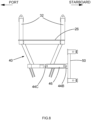
Figure 8 is a side view of the part shown inFigure 7 in a first configuration; -
Figure 9 is a side view of the part shown inFigure 7 in a second configuration; -
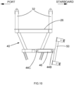
Figure 10 is a side view of the part shown inFigure 7 in a third configuration; -
Figure 11 is a side view of the part shown inFigure 7 in a fourth configuration; -
Figure 12 is a side view of the part shown inFigure 7 in a fifth configuration; and -
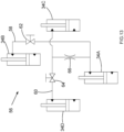
Figure 13 is a schematic drawing of a hydraulic circuit according to an embodiment of the invention; -
Figure 14 is a simplified illustration of the operation of connector means according to an embodiment of the invention; -
Figure 15 is a perspective view of the platform assembly ofFigure 1 showing more details of the tensioning means; -
Figure 16 is a perspective view of a platform assembly of a second embodiment of the present invention; and -
Figure 17 is a side view of a platform assembly of a second embodiment of the present invention; and -
Figure 18 is a front view of a platform assembly of a second embodiment of the present invention; and -
Figure 19 is a perspective view on a platform assembly of a second embodiment of the present invention with the platform cut away to show the locking cylinders; and -
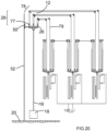
Figure 20 is a schematic view of the platform assembly ofFigure 16 showing operation of the tensioning means. -
- 10
- Platform assembly
- 12
- Derrick
- 14
- Vessel
- 16
- Riser
- 18
- Subsea stack
- 20
- Sea bed
- 22
- Working end of riser
- 24
- Moon pool
- 26
- Platform
- 28
- Tensioning means
- 30
- Wires
- 32
- Upwardly-extending beams
- 34
- Hydraulic cylinders
- 36
- Coiled tubing injector
- 38
- Coiled tubing bend restrictor
- 40
- Support frame
- 42
- Connector means
- 44
- Joints
- 46
- Rod
- 48
- Clamp
- 50
- Sliding frame
- 52
- Rails
- 54
- Surface flow tree
- 56
- Hydraulic circuit
- 58
- First hydraulic path
- 60
- Second hydraulic path
- 62
- First control valve
- 64
- Second control valve
- 66
- Pilot line
- 68
- First end of rod
- 70
- Second end of rod
- 72
- Ram rig
- 74
- Carriage
- 76
- Heave compensation system
- 77
- First Sheave
- 78
- Second Sheave
- 79
- Tension applying member
- 80
- First locking cylinder
- 81
- Second locking cylinder
- HA
- Hinge axis
- PORT
- Port side of the vessel
- STARBOARD
- Starboard side of the vessel
- Referring to
Figure 1 , aplatform assembly 10 is shown supported from aderrick 12 of avessel 14. Theplatform assembly 10 is mounted to ariser 16. Theriser 16 connects asubsea stack 18 at thesea bed 20 to machinery which is attached to a workingend 22 of theriser 16. Thevessel 14 is shown having amoon pool 24 extending through the vessel's hull. - Referring to
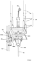
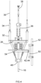
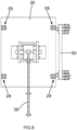
Figures 1 to 12 and2 to 6 in particular, theplatform assembly 10 is shown comprising aplatform 26 and tensioning means 28 for providing tension to theplatform 26 from thederrick 12. The tensioning means 28 comprises flexible tensile members in the form ofwires 30 extending from the derrick, rigid tensioning means in the form ofbeams 32 extending upwardly from the platform andhydraulic cylinders 34 connecting the wires to upper ends of the upwardly-extendingbeams 32. Also shown are acoiled tubing injector 36 tube and coiledtubing bend restrictor 38. - Referring to
Figures 1 to 12 and7 to 12 in particular, theplatform assembly 10 is shown having asupport frame 40, connector means 42 in the form of threejoints rigid rod 46, and a riser gripping device in the form of aclamp 48 for gripping an exterior of theriser 16 to maintain theplatform 26 in a fixed position relative to theriser 16. A rose joint, sometimes referred to as a rod end bearing or heim joint, is a spherical bearing which allows rotation about a pivot pin and an amount of rotational alignment in any other plane proportional to the dimensions of the joint. Theclamp 48 may be adapted to bring in riser pipes to build theriser 16 while theriser 16 is held in slips attached to moon pool doors. - The
platform assembly 10 is shown having a slidingframe 50 which is mounted to a pair ofrails 52 and connected to thesupport frame 40 via the threejoints rigid rod 46. The slidingframe 50, and thus theplatform assembly 10, may slide along therails 52. Therails 52 are fixed relative to thevessel 14 and are shown extending into themoon pool 24 of the vessel. - As shown in greater detail in
Figure 15 , thewires 30 are connected via aram rig 72 andcarriage 74 to aheave compensation system 76 which maintains as constant a tension in thewires 30 as reasonably practicable as theplatform 26 slides along therails 52 due to thevessel 14 rising and falling with the surface of the sea. The heave compensation system may have one or more of an active heave compensation system and a passive heave compensation system. The passive system may be used when theriser 16 is attached to thesubsea stack 18 and the active system may be used to make the connection. - The vertical motion of the
wires 30 is synchronised in response to theheave compensation system 76. Thewires 30 are attached to asingle carriage 74 on the ram-rig system 72 to lift and lower the platform. Synchronising vertical motion of thewires 30 provides a common vertical reference from which the tensioning means can vary the angle of theplatform 26, thereby simplifying operation of theplatform assembly 10. Alternatively motion of thewires 30 may be synchronised by attaching all of the wires to a single winch drum, or by attaching thewires 30 to separate winch drums which are themselves synchronised. - Also shown is a
surface flow tree 54 mounted to theriser 16 within the confines of thesupport frame 40, which is shown beneath the working area of theplatform 26. - The coiled
tubing injector tool 36 and surface flowtree 54 are examples of machinery which may be attached to the workingend 22 of theriser 16, and it is to be understood that other equipment may be attached to theriser 16 and used in combination with the platform assembly of the present invention. - The
hydraulic cylinders 34 are shown inFigures 1 to 6 connected between thewires 30 and the upwardly-extendingbeams 32, but one or more of thehydraulic cylinders 34 may be integrated into respective one or more beams 32. Alternatively, one or morehydraulic cylinders 34 may be directly connected to theplatform 26 in absence of respective one or more beams 32. In the embodiment of the invention shown in these Figures, there are four sets ofwires 30,hydraulic cylinders 34, and beams 32, but it is to be understood that sets of different numbers of wires, cylinders, and beams are possible. - The
hydraulic cylinders 34 may be connected to one another in hydraulic communication. In a preferred embodiment, there are fourhydraulic cylinders 34 in hydraulic communication which takes the form of ahydraulic circuit 56 illustrated schematically inFigure 13 . - Shown in
Figure 13 are first 34A, 34B and second 34C, 34D pairs ofhydraulic cylinders 34. Thecylinders platform 26, and are hydraulically connected to one another by a firsthydraulic path 58 to allow fluid to flow from eithercylinder cylinders platform 26 and are hydraulically connected by a secondhydraulic path 60 in the same manner as the first pair. Each pair ofcylinders 34A-34D is connected via arespective control valve - The two
hydraulic paths hydraulic line 66, such as a low flow capacity pilot line. Thispilot line 66 balances the pressures between each of thehydraulic paths lift wires 30. System redundancy is provided by restricting the maximum flow in thepilot line 66, which only needs a small flow in operation to balance the pressures, so that if there is a failure in one of thehydraulic paths cylinders 34 the two opposite wires can maintain their load. - The fluid
flow control valves cylinders 34. This enables the angle of theplatform 26 to be kept constant relative to thevessel 14 in circumstances where this is desirable, such as when theplatform 26 is not attached to theriser 16. - Instead of or in addition to providing hydraulic paths, fluid volumes in the
cylinders 34 may be individually controlled by appropriate flow control equipment to achieve and/or maintain any desired angle of the platform. The angle may be achieved and/or maintained by using sensors (not shown) to measure the relative angle of the vessel and platform and/or the position of thecylinders 34 and/or the fluid pressures in thecylinders 34, calculating a desired position, and commanding the flow control equipment to position theplatform 26 in the desired position. This may be performed with a closed loop control system. - The operation of the
platform assembly 10 will now be described. With thevessel 14 in a desired location above thesubsea stack 18, and theriser 16 secured to thesubsea stack 18, an upward tension is to be applied to theriser 16 to maintain theriser 16 upright. Theclamp 48 of the platform assembly is installed on the exterior of theriser 16, and appropriate machinery of thevessel 14, preferably via the heave compensation system, applies tension to thewires 30. The applied tension is transferred through thewires 30,hydraulic cylinders 34 and hydraulic fluid therein, upwardly-extendingbeams 32,platform 26,support frame 40, and theclamp 48 to theriser 16. Once this tension is achieved, theplatform 26 provides a working area. - It is necessary that workers on the working area experience as little acceleration as possible as the
vessel 14 moves, so that the workers can work safely. Further, as theplatform 26 is fixed relative to theriser 16 and held under tension by thewires 30, any motion of the vessel would exert a bending moment on the platform which could cause theplatform assembly 10 or theriser 16 to bend or break. - As the
vessel 14 pitches and rolls, the volumes of fluid in thehydraulic cylinders 34 change. In the embodiment ofFigure 13 , when thevessel 14 tilts so that a corner of theplatform 26 atcylinder 34A moves upward relative to thevessel 14 and the opposite corner of theplatform 26 atcylinder 34B moves downward relative to the vessel 14 (in other words, theplatform 26 rotates relative to thevessel 14 about an axis which is a locus in the plan view of the two points defined by the above two locations), fluid flows fromcylinder 34A tocylinder 34B, which causes the length ofcylinder 34A to decrease and the length ofcylinder 34B to increase accordingly. The remaining twocylinders cylinders 34 are so arranged on or above the platform that the axes of rotation they define are orthogonal to one another. This arrangement evenly distributes and shares the load applied about the location where theriser 16 meets theplatform 26 and ensures redundancy by enabling a pair ofcylinders 34 to support the load if the other pair fails. - As the lengths of the
cylinders 34 change in response to movement of thevessel 14 relative to theplatform 26, the tensions experienced by the points on theplatform 26 where thecylinders 34 orbeams 32 are mounted are kept equal (or as close to equal as practicable), thereby maintaining zero bending moment on the platform 26 (or as close to zero as practicable). This prevents workers on theplatform 26 from experiencing the pitch and roll of thevessel 14 that would be experienced if they were present on a deck of thevessel 14 and prevents relative motion between theplatform 26 and theriser 16, thereby increasing their safety while they work on the platform. It also prevents theplatform 26 andriser 16 from experiencing a potentially damaging bending moment. - The
platform assembly 10 is slideably connected via the connector means 42 and slidingframe 50 torails 52 which are mounted on thevessel 14, as shown inFigures 1 to 6 and described above. Thewires 30 are connected to the heave compensation system which compensates for heave of the vessel, and the co-operation between the slidingframe 50 and rails 52 enables theplatform 26 to be mounted to thevessel 14 while heave compensation is provided to the platform assembly. - As the
vessel 14 pitches and rolls, therails 52 correspondingly rotate relative to theplatform assembly 10. With no accommodation for this relative motion, the slidingframe 50 and rails 52 apply a bending moment to one another, which can cause damage to both therails 52 and theplatform assembly 10. - The function of the joints 44 and
rigid rod 46 of the connector means 42 will now be described with reference toFigures 7 to 12 . For descriptive purposes only, the starboard and port of the vessel are labelled onFigures 8 to 12 as to the right-hand side and left-hand side of the Figures respectively. - When the
vessel 14 is on a calm sea, the relative orientations of theplatform assembly 10 and therails 52 are as shown inFigures 7 and8 . InFigure 9 , the starboard of the vessel is rolling upwards, and inFigure 10 , the starboard of the vessel is rolling downwards. In these scenarios, the slidingframe 50 hinges relative to the rest of theplatform assembly 10 about an axis defined by a first rose joint 44A and a second rose joint 44B. The first and second rose joints 44A, 44B and the hinging axis HA they define can be seen inFigure 7 . The first rose joint 44A connects thesupport frame 40 beneath theplatform 26 to the slidingframe 50, and the second rose joint 44B connects the slidingframe 50 to afirst end 68 of therigid rod 46. Thesecond end 70 of therigid rod 46 is connected to thesupport frame 40 by a third rose joint 44C. - In
Figure 11 , the fore of thevessel 14 is pitching downward. InFigure 12 , the fore of thevessel 14 is pitching upward. In these scenarios, the three rose joints 44 accommodate the rotation of theplatform assembly 10 which rotates about an axis which is perpendicular to a longitudinal axis of the vessel and therigid rod 46 correspondingly hinges relative to the second and third rosejoints platform 26 relative to the other side. For example, inFigure 11 , the aft side of theplatform 26 falls relative to thevessel 14 and the fore side rises relative to thevessel 14. To accommodate this relative motion, the first and second rose joints 44A, 44B move relative to one another. - Referring to
Figures 11 and14 , relative movement between the first and second rose joints 44A, 44B is achieved by providing therigid rod 46 and third rose joint 44C. Therigid rod 46 hinges relative to the second and third rosejoints second joints Figure 14 shows the relative movement of therails 52,joints rod 46 as therails 52 rotate relative to theplatform 26 from a first orientation O1, wherein the vessel is upright on a calm sea, to a second orientation O2, wherein the aft side of theplatform 26 has risen relative to the vessel as in the scenario shown inFigure 11 . - A second sliding frame (not shown) may be installed beneath the
rails 52 and thesupport frame 40 to stabilise thesubsea stack 18 when thesubsea stack 18 is being launched and recovered through themoon pool 24. - The co-operation between the tensioning means 28 and the connector means 42 will now be described.
- It is important to have workers on the working area experience as little acceleration as possible while they are on the
platform 26 and while thevessel 14 pitches, rolls, and heaves. Therefore, theplatform assembly 10 is fixed relative to theriser 16 to provide as stable a working area as possible. When providing aplatform 26 that is fixed to the riser, it is important to maintain an upward tension on theriser 16 to keep theriser 16 in position, and it is desirable to exert as little bending moment as possible on theriser 16 to minimise the likelihood of damaging theriser 16. - The
hydraulic cylinders 34 described above balance the tensions in eachwire 30 by changing in length in response to changes in tension which arise from movement of thevessel 14 relative to theplatform 26. This prevents a net bending moment being applied to theplatform 26, and thus theriser 16. In situations such as particularly rough seas, it becomes desirable to attach theplatform assembly 10 to thevessel 14 to prevent theriser 16 from coming into contact with edges of themoon pool 24. It is desirable to do this in such a way that the bending moment applied to the platform assembly via thewires 30 remains as close to zero as reasonably practicable. To achieve this, theplatform assembly 10 is connected to therails 52 as described above, and the arrangement of the three rosejoints rigid rod 46 allow theplatform 26 to pivot relative to thevessel 14 to the extent provided by the dimensions of thejoints rod 46. Therefore, a safe working area is provided to workers, the likelihood of damage to theplatform 26 orriser 16 by a bending moment is minimised, and theplatform 26 is prevented from hitting the sides of themoon pool 24, thereby prevent damage to the hull of thevessel 14. - Referring to
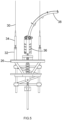
Figures 16 ,17 and18 , a platform assembly of a second embodiment of the present invention is shown. A plurality of first sheaves 77 (in the example shown inFigures 16 ,17 and18 , three sheaves are shown, but other numbers of sheaves could be used) are mounted to spaced apart locations on theplatform 26. A plurality ofsecond sheaves 78 are mounted to thederrick 12. The tensioning means includes a flexible tension applying member in the form of asteel cable 79, which passes around eachfirst sheave 77 and eachsecond sheave 78 in turn so that the sheaves are connected in series so as to apply generally the same tension to eachfirst sheave 77 location on the platform. As thevessel 14 moves relative to the top of theriser 16, theplatform 26 can change angle about orthogonal horizontal axes relative to the vessel, and the distance between eachfirst sheave 77 andsecond sheave 78 will change to compensate for this angular change. The end of the flexibletension applying member 79 can be connected to a winch or ram-rig system (not shown) to allow for translation of theplatform 26 along therails 52. - Referring to
Figure 19 , the platform assembly of the second embodiment of the present invention is shown with the platform cut away. The connecting means between theplatform 26 and thecarriage 50 is similar to the connecting means described in the first embodiment with the addition of a firsthydraulic cylinder 80 and a secondhydraulic cylinder 81 connected at two different positions between theplatform 26 and thecarriage 50. The first and secondhydraulic cylinders platform 26 with respect to thecarriage 50 about two orthogonal horizontal axes changes. With the first and secondhydraulic cylinders 80,82 in float, theplatform 26 is free to change angle with respect to thevessel 14 under the influence of theriser 16. With the first andsecond cylinders platform 26 andvessel 14 can be fixed. -
Figure 20 is a schematic view of the platform assembly of the second embodiment ofFigure 16 showing operation of the tensioning means and a typical reeving arrangement to connect theplatform 26 tensioning means 28 with a heave compensated ram-rig. - It will be appreciated by persons skilled in the art that the above embodiment has been described by way of example only, and not in any limitative sense, and that various alterations and modifications are possible without departure from the scope of the invention as defined by the appended claims.
Claims (15)
- A platform assembly (10) for providing a work area around a well riser (16), the assembly comprising:a platform (26) configured to be attached to the well riser (16); andtensioning means (28) for applying a tension force for supporting the platform (26) relative to a vessel (14) and supporting the well riser (16), wherein the tensioning means (28) is adapted to apply a respective tension force at each of a plurality of locations on the platform (26), and at least one first part of the tensioning means (28) is adapted to change in length in response to angular movement of the vessel (14) relative to the well riser (16);the platform assembly (10) further comprising connecting means (42, 50) for connectingthe platform (26) to the vessel (14), wherein said connecting means (42, 50) are configured to restrain the platform (26) against movement parallel to first and second axes, and is able to move parallel to a third axis, wherein said first, second and third axes are substantially perpendicular to each other;wherein said connecting means (42, 50) are configured to restrain the platform (26) from pivoting about said third axis but is able to pivot about said first and second axes;wherein the platform assembly (10) is slideably moveable through said connecting means (42, 50) relative to the vessel (14) along rails (52), wherein the rails (52) are configured to rotate relative to the platform assembly (10).
- A platform assembly according to claim 1, wherein the tensioning means (28) comprises at least one flexible tension applying member (79) adapted to apply substantially the same tension to a plurality of said locations on the platform (26).
- A platform assembly according to claim 2, wherein the tensioning means (28) further comprises a plurality of first sheaves (77) adapted to be mounted to the platform (26) and at least one said flexible tension applying member (79) is adapted to apply a tension to a plurality of said first sheaves (77).
- A platform assembly according to claim 3, wherein at least one said first part of the tensioning means (28) comprises a respective part of a said flexible tension applying member (79) extending between a said first sheave (77) and the vessel (14).
- A platform assembly according to claim 3 or 4, wherein the tensioning means (28) further comprises a plurality of second sheaves (78) adapted to be mounted to the vessel (14) and at least one said flexible tension applying member (79) is adapted to apply a tension to a plurality of said second sheaves (78).
- A platform assembly according to any one of the preceding claims, wherein the tensioning means (28) comprises a plurality of tension applying members (79) adapted to be interconnected to apply substantially the same tension to a plurality of said locations on the platform (10).
- A platform assembly according to claim 6, wherein a plurality of said tension applying members (79) are flexible.
- A platform assembly according to claim 7, wherein a plurality of said flexible tension applying members (79) are adapted to be connected in series.
- A platform assembly according to any one of the preceding claims, wherein at least one first part of the tensioning means (28) comprises at least one respective hydraulic cylinder (34).
- A platform assembly according to claim 9, including one or more of the following features:(i) wherein at least two said hydraulic cylinders (34) are in fluid communication with one another;(ii) further comprising fluid control means for controlling a fluid volume of at least one hydraulic cylinder (34); or(iii) further comprising at least one fluid flow control valve for controlling a flow of fluid into or out of at least one hydraulic cylinder (34).
- A platform assembly according to claim 10, including one or more of the following features:(i) wherein the plurality of hydraulic cylinders (34) are so linked in hydraulic communication as to enable the platform to pivot about first and second axes relative to the vessel (14), wherein said first and second axes are substantially perpendicular to each other.(ii) further comprising at least one sensor for determining at least one of (i) an angle between the platform (26) and the vessel (14); (ii) a fluid volume of at least one hydraulic cylinder (34); and (iii) a fluid pressure of at least one hydraulic cylinder (34);(iii) wherein the fluid control means is configured to change a fluid volume of at least one hydraulic cylinder (34) responsive to a determination of at least one sensor; or(iv) wherein the at least one fluid flow control valve is configured to be closed for enabling the platform (26) to be kept stationary relative to the vessel (14).
- A platform assembly according to any one of the preceding claims, wherein the tensioning means (28) is adapted to control a height of the platform (26) relative to the vessel (14) in response to movement of the vessel (14).
- A platform assembly according to claim 12, wherein the tensioning means (28) comprises at least one respective tensile member (30) connected to each of a plurality of locations on said assembly (10), wherein vertical motion of said tensile members (30) is synchronised in use.
- A platform assembly according to claim 1, wherein the connecting means (42) comprises a first joint (44A) configured to mount the platform (26) to the vessel (14), a second joint (44B) configured to mount a rigid member (46) to the vessel, and a third joint (44C) configured to mount the rigid member (46) to the platform (26).
- A platform assembly according to claim 14, wherein at least one joint (44A, 44B, 44C) is a rose joint.
Applications Claiming Priority (3)
| Application Number | Priority Date | Filing Date | Title |
|---|---|---|---|
| EP19159138.7A EP3699079A1 (en) | 2019-02-25 | 2019-02-25 | Platform assembly |
| GBGB1909624.7A GB201909624D0 (en) | 2019-02-25 | 2019-07-04 | Platform assembly |
| PCT/EP2020/052703 WO2020173670A1 (en) | 2019-02-25 | 2020-02-04 | Platform assembly |
Publications (3)
| Publication Number | Publication Date |
|---|---|
| EP3931076A1 EP3931076A1 (en) | 2022-01-05 |
| EP3931076B1 true EP3931076B1 (en) | 2024-04-03 |
| EP3931076C0 EP3931076C0 (en) | 2024-04-03 |
Family
ID=65576228
Family Applications (2)
| Application Number | Title | Priority Date | Filing Date |
|---|---|---|---|
| EP19159138.7A Pending EP3699079A1 (en) | 2019-02-25 | 2019-02-25 | Platform assembly |
| EP20702154.4A Active EP3931076B1 (en) | 2019-02-25 | 2020-02-04 | Platform assembly |
Family Applications Before (1)
| Application Number | Title | Priority Date | Filing Date |
|---|---|---|---|
| EP19159138.7A Pending EP3699079A1 (en) | 2019-02-25 | 2019-02-25 | Platform assembly |
Country Status (5)
| Country | Link |
|---|---|
| US (1) | US11466521B2 (en) |
| EP (2) | EP3699079A1 (en) |
| AU (1) | AU2020227149A1 (en) |
| GB (1) | GB201909624D0 (en) |
| WO (1) | WO2020173670A1 (en) |
Families Citing this family (3)
| Publication number | Priority date | Publication date | Assignee | Title |
|---|---|---|---|---|
| DK180224B1 (en) * | 2018-06-06 | 2020-08-21 | Maersk Drilling As | Method and system for mitigating cable wear in a hoisting system |
| BR112022009128A2 (en) * | 2019-11-21 | 2022-07-26 | Oceaneering Int Inc | EQUIPMENT AND METHOD TO ASSIST IN THE IMPLEMENTATION OF FLEXITUBE |
| US20260110225A1 (en) * | 2024-10-21 | 2026-04-23 | Halliburton Energy Services, Inc. | Coiled tubing injector system including a trolley track and trolley for support thereof |
Citations (4)
| Publication number | Priority date | Publication date | Assignee | Title |
|---|---|---|---|---|
| EP1103459A1 (en) * | 1999-11-24 | 2001-05-30 | Mercur Slimhole Drilling and Intervention AS | Arrangement for heave and tidal movement compensation |
| US6470969B1 (en) * | 1999-09-09 | 2002-10-29 | Moss Maritime As | Arrangement on a floating device for overhauling offshore hydrocarbon wells |
| WO2011008835A2 (en) * | 2009-07-15 | 2011-01-20 | My Technologies, L.L.C. | Downhole intervention |
| US20170341717A1 (en) * | 2014-10-24 | 2017-11-30 | Itrec B.V. | Offshore drilling system, vessel and method |
Family Cites Families (9)
| Publication number | Priority date | Publication date | Assignee | Title |
|---|---|---|---|---|
| GB8302292D0 (en) * | 1983-01-27 | 1983-03-02 | British Petroleum Co Plc | Riser support system |
| US6691784B1 (en) * | 1999-08-31 | 2004-02-17 | Kvaerner Oil & Gas A.S. | Riser tensioning system |
| US6343893B1 (en) * | 1999-11-29 | 2002-02-05 | Mercur Slimhole Drilling And Intervention As | Arrangement for controlling floating drilling and intervention vessels |
| GB2358032B (en) * | 2000-01-05 | 2002-03-27 | Sedco Forex Internat Inc | Method and apparatus for drillig subsea wells |
| NO317079B1 (en) * | 2002-08-02 | 2004-08-02 | Maritime Hydraulics As | The riser Trekka scheme |
| EP2186993B1 (en) * | 2008-11-17 | 2019-06-26 | Saipem S.p.A. | Vessel for operating on underwater wells and working method of said vessel |
| US9611706B2 (en) * | 2015-08-11 | 2017-04-04 | Fugro N.V. | Well intervention device and offshore floating installation |
| MX2019005585A (en) * | 2016-11-17 | 2019-08-12 | C Wright David | Motion compensating floors system and method. |
| NL2018018B1 (en) * | 2016-12-16 | 2018-06-26 | Itrec Bv | An offshore subsea wellbore activities system |
-
2019
- 2019-02-25 EP EP19159138.7A patent/EP3699079A1/en active Pending
- 2019-07-04 GB GBGB1909624.7A patent/GB201909624D0/en not_active Ceased
-
2020
- 2020-02-04 WO PCT/EP2020/052703 patent/WO2020173670A1/en not_active Ceased
- 2020-02-04 AU AU2020227149A patent/AU2020227149A1/en not_active Abandoned
- 2020-02-04 US US17/433,880 patent/US11466521B2/en active Active
- 2020-02-04 EP EP20702154.4A patent/EP3931076B1/en active Active
Patent Citations (4)
| Publication number | Priority date | Publication date | Assignee | Title |
|---|---|---|---|---|
| US6470969B1 (en) * | 1999-09-09 | 2002-10-29 | Moss Maritime As | Arrangement on a floating device for overhauling offshore hydrocarbon wells |
| EP1103459A1 (en) * | 1999-11-24 | 2001-05-30 | Mercur Slimhole Drilling and Intervention AS | Arrangement for heave and tidal movement compensation |
| WO2011008835A2 (en) * | 2009-07-15 | 2011-01-20 | My Technologies, L.L.C. | Downhole intervention |
| US20170341717A1 (en) * | 2014-10-24 | 2017-11-30 | Itrec B.V. | Offshore drilling system, vessel and method |
Also Published As
| Publication number | Publication date |
|---|---|
| EP3931076A1 (en) | 2022-01-05 |
| US11466521B2 (en) | 2022-10-11 |
| WO2020173670A1 (en) | 2020-09-03 |
| US20220049559A1 (en) | 2022-02-17 |
| EP3699079A1 (en) | 2020-08-26 |
| AU2020227149A1 (en) | 2021-10-07 |
| GB201909624D0 (en) | 2019-08-21 |
| EP3931076C0 (en) | 2024-04-03 |
Similar Documents
| Publication | Publication Date | Title |
|---|---|---|
| US11466521B2 (en) | Platform assembly | |
| EP1740866B1 (en) | Marine pipelay system and method | |
| US20200070935A1 (en) | System and Method for Compensation of Motions of a Floating Vessel | |
| US7063159B2 (en) | Multi-purpose coiled tubing handling system | |
| US4688764A (en) | Crown block compensator | |
| US4620692A (en) | Crown block compensator | |
| WO2001016458A1 (en) | Riser tensioning system | |
| US20150321734A1 (en) | Hybrid gimbal support structure | |
| US6431284B1 (en) | Gimbaled table riser support system | |
| NO341753B1 (en) | Motion Compensation System | |
| NO344581B1 (en) | Supplementary tightening system for improved platform design and related procedures | |
| EP3601141B1 (en) | A lifting device | |
| EP1103459A1 (en) | Arrangement for heave and tidal movement compensation | |
| US10253579B2 (en) | Motion compensation system for a load hanging from a mobile unit with a main cylinder and a secondary cylinder | |
| NO842405L (en) | DEVICE AND PROCEDURE FOR SUPPLYING A HYDROCARBON PRODUCTION SYSTEM ASSOCIATED WITH A SHIP | |
| CN113784887B (en) | Offshore systems, vessels and methods for performing activities related to subsea drilling holes | |
| GB2175945A (en) | Offshore production systems | |
| CN107107997A (en) | For handling large-scale and heavy constructions system and method from Attention problems ship | |
| KR20150120726A (en) | Bunkering vessel, balancing structure and method on center of gravity thereof | |
| NL2011872C2 (en) | System and method for deploying/operating tool and heave compensation for same. | |
| NO347979B1 (en) | Semi active heave compensator | |
| OA17421A (en) | Hybrid gimbal support structure. |
Legal Events
| Date | Code | Title | Description |
|---|---|---|---|
| STAA | Information on the status of an ep patent application or granted ep patent |
Free format text: STATUS: UNKNOWN |
|
| STAA | Information on the status of an ep patent application or granted ep patent |
Free format text: STATUS: THE INTERNATIONAL PUBLICATION HAS BEEN MADE |
|
| PUAI | Public reference made under article 153(3) epc to a published international application that has entered the european phase |
Free format text: ORIGINAL CODE: 0009012 |
|
| STAA | Information on the status of an ep patent application or granted ep patent |
Free format text: STATUS: REQUEST FOR EXAMINATION WAS MADE |
|
| 17P | Request for examination filed |
Effective date: 20210805 |
|
| AK | Designated contracting states |
Kind code of ref document: A1 Designated state(s): AL AT BE BG CH CY CZ DE DK EE ES FI FR GB GR HR HU IE IS IT LI LT LU LV MC MK MT NL NO PL PT RO RS SE SI SK SM TR |
|
| DAV | Request for validation of the european patent (deleted) | ||
| DAX | Request for extension of the european patent (deleted) | ||
| GRAP | Despatch of communication of intention to grant a patent |
Free format text: ORIGINAL CODE: EPIDOSNIGR1 |
|
| STAA | Information on the status of an ep patent application or granted ep patent |
Free format text: STATUS: GRANT OF PATENT IS INTENDED |
|
| INTG | Intention to grant announced |
Effective date: 20231018 |
|
| GRAS | Grant fee paid |
Free format text: ORIGINAL CODE: EPIDOSNIGR3 |
|
| GRAA | (expected) grant |
Free format text: ORIGINAL CODE: 0009210 |
|
| STAA | Information on the status of an ep patent application or granted ep patent |
Free format text: STATUS: THE PATENT HAS BEEN GRANTED |
|
| AK | Designated contracting states |
Kind code of ref document: B1 Designated state(s): AL AT BE BG CH CY CZ DE DK EE ES FI FR GB GR HR HU IE IS IT LI LT LU LV MC MK MT NL NO PL PT RO RS SE SI SK SM TR |
|
| REG | Reference to a national code |
Ref country code: CH Ref legal event code: EP |
|
| REG | Reference to a national code |
Ref country code: IE Ref legal event code: FG4D |
|
| REG | Reference to a national code |
Ref country code: DE Ref legal event code: R096 Ref document number: 602020028273 Country of ref document: DE |
|
| U01 | Request for unitary effect filed |
Effective date: 20240423 |
|
| U07 | Unitary effect registered |
Designated state(s): AT BE BG DE DK EE FI FR IT LT LU LV MT NL PT SE SI Effective date: 20240430 |
|
| PG25 | Lapsed in a contracting state [announced via postgrant information from national office to epo] |
Ref country code: IS Free format text: LAPSE BECAUSE OF FAILURE TO SUBMIT A TRANSLATION OF THE DESCRIPTION OR TO PAY THE FEE WITHIN THE PRESCRIBED TIME-LIMIT Effective date: 20240803 |
|
| PG25 | Lapsed in a contracting state [announced via postgrant information from national office to epo] |
Ref country code: HR Free format text: LAPSE BECAUSE OF FAILURE TO SUBMIT A TRANSLATION OF THE DESCRIPTION OR TO PAY THE FEE WITHIN THE PRESCRIBED TIME-LIMIT Effective date: 20240403 |
|
| PG25 | Lapsed in a contracting state [announced via postgrant information from national office to epo] |
Ref country code: GR Free format text: LAPSE BECAUSE OF FAILURE TO SUBMIT A TRANSLATION OF THE DESCRIPTION OR TO PAY THE FEE WITHIN THE PRESCRIBED TIME-LIMIT Effective date: 20240704 |
|
| PG25 | Lapsed in a contracting state [announced via postgrant information from national office to epo] |
Ref country code: ES Free format text: LAPSE BECAUSE OF FAILURE TO SUBMIT A TRANSLATION OF THE DESCRIPTION OR TO PAY THE FEE WITHIN THE PRESCRIBED TIME-LIMIT Effective date: 20240403 |
|
| PG25 | Lapsed in a contracting state [announced via postgrant information from national office to epo] |
Ref country code: CZ Free format text: LAPSE BECAUSE OF FAILURE TO SUBMIT A TRANSLATION OF THE DESCRIPTION OR TO PAY THE FEE WITHIN THE PRESCRIBED TIME-LIMIT Effective date: 20240403 |
|
| PG25 | Lapsed in a contracting state [announced via postgrant information from national office to epo] |
Ref country code: PL Free format text: LAPSE BECAUSE OF FAILURE TO SUBMIT A TRANSLATION OF THE DESCRIPTION OR TO PAY THE FEE WITHIN THE PRESCRIBED TIME-LIMIT Effective date: 20240403 |
|
| PG25 | Lapsed in a contracting state [announced via postgrant information from national office to epo] |
Ref country code: PL Free format text: LAPSE BECAUSE OF FAILURE TO SUBMIT A TRANSLATION OF THE DESCRIPTION OR TO PAY THE FEE WITHIN THE PRESCRIBED TIME-LIMIT Effective date: 20240403 Ref country code: IS Free format text: LAPSE BECAUSE OF FAILURE TO SUBMIT A TRANSLATION OF THE DESCRIPTION OR TO PAY THE FEE WITHIN THE PRESCRIBED TIME-LIMIT Effective date: 20240803 Ref country code: HR Free format text: LAPSE BECAUSE OF FAILURE TO SUBMIT A TRANSLATION OF THE DESCRIPTION OR TO PAY THE FEE WITHIN THE PRESCRIBED TIME-LIMIT Effective date: 20240403 Ref country code: GR Free format text: LAPSE BECAUSE OF FAILURE TO SUBMIT A TRANSLATION OF THE DESCRIPTION OR TO PAY THE FEE WITHIN THE PRESCRIBED TIME-LIMIT Effective date: 20240704 Ref country code: ES Free format text: LAPSE BECAUSE OF FAILURE TO SUBMIT A TRANSLATION OF THE DESCRIPTION OR TO PAY THE FEE WITHIN THE PRESCRIBED TIME-LIMIT Effective date: 20240403 Ref country code: CZ Free format text: LAPSE BECAUSE OF FAILURE TO SUBMIT A TRANSLATION OF THE DESCRIPTION OR TO PAY THE FEE WITHIN THE PRESCRIBED TIME-LIMIT Effective date: 20240403 Ref country code: RS Free format text: LAPSE BECAUSE OF FAILURE TO SUBMIT A TRANSLATION OF THE DESCRIPTION OR TO PAY THE FEE WITHIN THE PRESCRIBED TIME-LIMIT Effective date: 20240703 |
|
| REG | Reference to a national code |
Ref country code: DE Ref legal event code: R097 Ref document number: 602020028273 Country of ref document: DE |
|
| PG25 | Lapsed in a contracting state [announced via postgrant information from national office to epo] |
Ref country code: RO Free format text: LAPSE BECAUSE OF FAILURE TO SUBMIT A TRANSLATION OF THE DESCRIPTION OR TO PAY THE FEE WITHIN THE PRESCRIBED TIME-LIMIT Effective date: 20240403 Ref country code: SK Free format text: LAPSE BECAUSE OF FAILURE TO SUBMIT A TRANSLATION OF THE DESCRIPTION OR TO PAY THE FEE WITHIN THE PRESCRIBED TIME-LIMIT Effective date: 20240403 |
|
| PG25 | Lapsed in a contracting state [announced via postgrant information from national office to epo] |
Ref country code: SM Free format text: LAPSE BECAUSE OF FAILURE TO SUBMIT A TRANSLATION OF THE DESCRIPTION OR TO PAY THE FEE WITHIN THE PRESCRIBED TIME-LIMIT Effective date: 20240403 |
|
| PG25 | Lapsed in a contracting state [announced via postgrant information from national office to epo] |
Ref country code: SM Free format text: LAPSE BECAUSE OF FAILURE TO SUBMIT A TRANSLATION OF THE DESCRIPTION OR TO PAY THE FEE WITHIN THE PRESCRIBED TIME-LIMIT Effective date: 20240403 Ref country code: SK Free format text: LAPSE BECAUSE OF FAILURE TO SUBMIT A TRANSLATION OF THE DESCRIPTION OR TO PAY THE FEE WITHIN THE PRESCRIBED TIME-LIMIT Effective date: 20240403 Ref country code: RO Free format text: LAPSE BECAUSE OF FAILURE TO SUBMIT A TRANSLATION OF THE DESCRIPTION OR TO PAY THE FEE WITHIN THE PRESCRIBED TIME-LIMIT Effective date: 20240403 |
|
| PLBE | No opposition filed within time limit |
Free format text: ORIGINAL CODE: 0009261 |
|
| STAA | Information on the status of an ep patent application or granted ep patent |
Free format text: STATUS: NO OPPOSITION FILED WITHIN TIME LIMIT |
|
| 26N | No opposition filed |
Effective date: 20250106 |
|
| U20 | Renewal fee for the european patent with unitary effect paid |
Year of fee payment: 6 Effective date: 20250226 |
|
| PG25 | Lapsed in a contracting state [announced via postgrant information from national office to epo] |
Ref country code: MC Free format text: LAPSE BECAUSE OF FAILURE TO SUBMIT A TRANSLATION OF THE DESCRIPTION OR TO PAY THE FEE WITHIN THE PRESCRIBED TIME-LIMIT Effective date: 20240403 |
|
| PG25 | Lapsed in a contracting state [announced via postgrant information from national office to epo] |
Ref country code: IE Free format text: LAPSE BECAUSE OF NON-PAYMENT OF DUE FEES Effective date: 20250204 |
|
| REG | Reference to a national code |
Ref country code: CH Ref legal event code: U11 Free format text: ST27 STATUS EVENT CODE: U-0-0-U10-U11 (AS PROVIDED BY THE NATIONAL OFFICE) Effective date: 20260301 |
|
| U20 | Renewal fee for the european patent with unitary effect paid |
Year of fee payment: 7 Effective date: 20260226 |
|
| PGFP | Annual fee paid to national office [announced via postgrant information from national office to epo] |
Ref country code: GB Payment date: 20260225 Year of fee payment: 7 |
|
| PGFP | Annual fee paid to national office [announced via postgrant information from national office to epo] |
Ref country code: NO Payment date: 20260302 Year of fee payment: 7 |
|
| PGFP | Annual fee paid to national office [announced via postgrant information from national office to epo] |
Ref country code: CH Payment date: 20260301 Year of fee payment: 7 |