EP3930557B1 - Cyclone separation device - Google Patents
Cyclone separation device Download PDFInfo
- Publication number
- EP3930557B1 EP3930557B1 EP20702838.2A EP20702838A EP3930557B1 EP 3930557 B1 EP3930557 B1 EP 3930557B1 EP 20702838 A EP20702838 A EP 20702838A EP 3930557 B1 EP3930557 B1 EP 3930557B1
- Authority
- EP
- European Patent Office
- Prior art keywords
- dirt
- cyclone
- separation device
- chamber
- edge
- Prior art date
- Legal status (The legal status is an assumption and is not a legal conclusion. Google has not performed a legal analysis and makes no representation as to the accuracy of the status listed.)
- Active
Links
Images
Classifications
-
- B—PERFORMING OPERATIONS; TRANSPORTING
- B04—CENTRIFUGAL APPARATUS OR MACHINES FOR CARRYING-OUT PHYSICAL OR CHEMICAL PROCESSES
- B04C—APPARATUS USING FREE VORTEX FLOW, e.g. CYCLONES
- B04C5/00—Apparatus in which the axial direction of the vortex is reversed
- B04C5/14—Construction of the underflow ducting; Apex constructions; Discharge arrangements ; discharge through sidewall provided with a few slits or perforations
- B04C5/185—Dust collectors
-
- A—HUMAN NECESSITIES
- A47—FURNITURE; DOMESTIC ARTICLES OR APPLIANCES; COFFEE MILLS; SPICE MILLS; SUCTION CLEANERS IN GENERAL
- A47L—DOMESTIC WASHING OR CLEANING; SUCTION CLEANERS IN GENERAL
- A47L9/00—Details or accessories of suction cleaners, e.g. mechanical means for controlling the suction or for effecting pulsating action; Storing devices specially adapted to suction cleaners or parts thereof; Carrying-vehicles specially adapted for suction cleaners
- A47L9/0081—Means for exhaust-air diffusion; Means for sound or vibration damping
-
- A—HUMAN NECESSITIES
- A47—FURNITURE; DOMESTIC ARTICLES OR APPLIANCES; COFFEE MILLS; SPICE MILLS; SUCTION CLEANERS IN GENERAL
- A47L—DOMESTIC WASHING OR CLEANING; SUCTION CLEANERS IN GENERAL
- A47L9/00—Details or accessories of suction cleaners, e.g. mechanical means for controlling the suction or for effecting pulsating action; Storing devices specially adapted to suction cleaners or parts thereof; Carrying-vehicles specially adapted for suction cleaners
- A47L9/10—Filters; Dust separators; Dust removal; Automatic exchange of filters
- A47L9/16—Arrangement or disposition of cyclones or other devices with centrifugal action
- A47L9/1608—Cyclonic chamber constructions
-
- A—HUMAN NECESSITIES
- A47—FURNITURE; DOMESTIC ARTICLES OR APPLIANCES; COFFEE MILLS; SPICE MILLS; SUCTION CLEANERS IN GENERAL
- A47L—DOMESTIC WASHING OR CLEANING; SUCTION CLEANERS IN GENERAL
- A47L9/00—Details or accessories of suction cleaners, e.g. mechanical means for controlling the suction or for effecting pulsating action; Storing devices specially adapted to suction cleaners or parts thereof; Carrying-vehicles specially adapted for suction cleaners
- A47L9/10—Filters; Dust separators; Dust removal; Automatic exchange of filters
- A47L9/16—Arrangement or disposition of cyclones or other devices with centrifugal action
- A47L9/1658—Construction of outlets
-
- A—HUMAN NECESSITIES
- A47—FURNITURE; DOMESTIC ARTICLES OR APPLIANCES; COFFEE MILLS; SPICE MILLS; SUCTION CLEANERS IN GENERAL
- A47L—DOMESTIC WASHING OR CLEANING; SUCTION CLEANERS IN GENERAL
- A47L9/00—Details or accessories of suction cleaners, e.g. mechanical means for controlling the suction or for effecting pulsating action; Storing devices specially adapted to suction cleaners or parts thereof; Carrying-vehicles specially adapted for suction cleaners
- A47L9/10—Filters; Dust separators; Dust removal; Automatic exchange of filters
- A47L9/16—Arrangement or disposition of cyclones or other devices with centrifugal action
- A47L9/1683—Dust collecting chambers; Dust collecting receptacles
-
- B—PERFORMING OPERATIONS; TRANSPORTING
- B04—CENTRIFUGAL APPARATUS OR MACHINES FOR CARRYING-OUT PHYSICAL OR CHEMICAL PROCESSES
- B04C—APPARATUS USING FREE VORTEX FLOW, e.g. CYCLONES
- B04C5/00—Apparatus in which the axial direction of the vortex is reversed
- B04C5/08—Vortex chamber constructions
- B04C5/103—Bodies or members, e.g. bulkheads, guides, in the vortex chamber
-
- B—PERFORMING OPERATIONS; TRANSPORTING
- B04—CENTRIFUGAL APPARATUS OR MACHINES FOR CARRYING-OUT PHYSICAL OR CHEMICAL PROCESSES
- B04C—APPARATUS USING FREE VORTEX FLOW, e.g. CYCLONES
- B04C5/00—Apparatus in which the axial direction of the vortex is reversed
- B04C5/12—Construction of the overflow ducting, e.g. diffusing or spiral exits
- B04C5/13—Construction of the overflow ducting, e.g. diffusing or spiral exits formed as a vortex finder and extending into the vortex chamber; Discharge from vortex finder otherwise than at the top of the cyclone; Devices for controlling the overflow
-
- B—PERFORMING OPERATIONS; TRANSPORTING
- B04—CENTRIFUGAL APPARATUS OR MACHINES FOR CARRYING-OUT PHYSICAL OR CHEMICAL PROCESSES
- B04C—APPARATUS USING FREE VORTEX FLOW, e.g. CYCLONES
- B04C5/00—Apparatus in which the axial direction of the vortex is reversed
- B04C5/14—Construction of the underflow ducting; Apex constructions; Discharge arrangements ; discharge through sidewall provided with a few slits or perforations
-
- B—PERFORMING OPERATIONS; TRANSPORTING
- B04—CENTRIFUGAL APPARATUS OR MACHINES FOR CARRYING-OUT PHYSICAL OR CHEMICAL PROCESSES
- B04C—APPARATUS USING FREE VORTEX FLOW, e.g. CYCLONES
- B04C5/00—Apparatus in which the axial direction of the vortex is reversed
- B04C5/12—Construction of the overflow ducting, e.g. diffusing or spiral exits
- B04C5/13—Construction of the overflow ducting, e.g. diffusing or spiral exits formed as a vortex finder and extending into the vortex chamber; Discharge from vortex finder otherwise than at the top of the cyclone; Devices for controlling the overflow
- B04C2005/136—Baffles in the vortex finder
Definitions
- the invention relates to a cyclone separation device, and to a vacuum cleaner comprising such a cyclone separation device.
- a cyclone technology can be used in a bag-less vacuum cleaner to separate dirt particles from the dirty air flowing through the appliance.
- the dirt particles are collected in a special dust bucket after separation from the main air flow.
- Cyclone separators allow vacuum cleaners to maintain a constant vacuuming performance.
- the air enters the cyclone chamber at the bottom and will flow cyclonic due to the geometry. Dirt particles are pushed outwards by the generated centrifugal forces and follow a spiral path upwards towards the exit of the cyclone chamber into the dust bucket.
- the air flow in the cyclone chamber will exit the system at the center.
- the air inside the cyclone chamber is spinning fast and passes the exit ridges at the top.
- US2014373307 discloses a cyclone separation device for separating particles from air and a cyclone vacuum cleaner. It has the objective to reduce noise without impairing the dirt separation performance. This is achieved an arrangement comprising a cyclone chamber, a dirt collecting chamber arranged adjacent to the cyclone chamber for collecting dirt particles separated from air, a dirt-duct between the cyclone chamber and the dirt collecting chamber for allowing dirt particles to pass from the cyclone chamber towards the dirt collecting chamber, and an air-guide arranged adjacent to the dirt-duct for reducing the momentum of the air in the dirt-duct.
- An aspect of the invention provides a cyclone separation device that comprises a cyclone chamber for separating dirt from incoming air, a dirt collecting chamber arranged adjacent to the cyclone chamber for collecting dirt particles separated from air, and a dirt duct between the cyclone chamber and the dirt collecting chamber for allowing dirt particles to exit the cyclone chamber into the dirt collecting chamber.
- the dirt duct has an edge protruding into a direction at an angle to the dirt duct at an exit ridge of the cyclone chamber that is first encountered by the air rotating in the cyclone chamber.
- the edge is formed by a tangential extension of a wall of the cyclone chamber.
- a width of the edge is at least 5 mm, and more preferably at least 8 mm, and even more preferably 12 mm.
- a vacuum cleaner advantageously comprises such a cyclone separation device.
- Embodiments of the invention provide a solution having a special new shaped dirt outlet geometry from the cyclone chamber towards the dust bucket that does not need the disruptor part inside the cyclone chamber of US2014373307 .
- Vortex shedding at the first exit ridge of the dirt exit is limited. These vortices are responsible for the alternating forces attenuating the mass of the Helmholtz system. Limiting the vortex shedding means that the size of the vortices becomes smaller. By creating a sharp exit ridge, the vortex shedding is less.
- This solution, placed parallel to the main flow direction, is therefore not influencing the rotational movement of the air column in the cyclone chamber. This results in significantly better separation performance as well as a reduced tonal noise level.
- the expression “sharp” means that air cannot easily follow the surface along which it is flowing so as to enter the dirt duct, as the air would have to make a turn of at least 90° if it wished to follow that surface so as to enter the dirt duct. As a result of this need to make a turn of at least 90° if the air wished to follow the surface along which it is flowing, the ability for the air to generate large vortices resulting in disturbing noise levels is impeded.
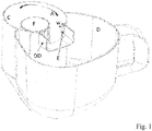
- Fig. 1 shows an embodiment of a cyclone separation device in accordance with the present invention.
- Fig. 1 shows an embodiment of a cyclone separation device in accordance with the present invention.
- the cyclone separation device has a cyclone chamber C, a dirt collecting chamber D arranged adjacent to the cyclone chamber C for collecting dirt particles separated from air, a dirt duct DD between the cyclone chamber C and the dirt collecting chamber D for allowing dirt particles to pass from the cyclone chamber C towards the dirt collecting chamber D.
- the dirt duct DD may generally extend in a longitudinal direction that is a radial to the cyclone chamber C.
- the cyclone chamber C may have a cylinder-shaped vortex finder F having a plurality of stationary vanes at its outer circumference, or some other air exit for allowing air with a reduced amount of dirt to leave the cyclone chamber C.
- Air A is rotating clockwise in the cyclone chamber C.
- an edge E protrudes into the dirt duct DD at a first exit ridge of the dirt duct DD.
- the edge E is formed by a tangential extension of the cyclone chamber wall, and has the same thickness as that wall.
- a width w of the edge E is at least 5 mm, and preferably at least 8 mm, and more preferably 12 mm. It is practical if the edge E extends along the entire height of the dirt duct DD, as shown.
- the dirt duct DD may have a roof.
- the edge E might also be a serrated edge, or an edge placed at an angle with regard to the air flow direction, etc... in order to negate coherent vortex shedding.
- the edge E may be perpendicular to a wall of the dirt duct DD.
- the thickness of the edge E may be different from the thickness of the wall of the cyclone chamber C. In general, preventing coherent (simultaneously generated) vortices reduce the attenuation of the Helmholtz system.
- a space between the edge E and the wall of the dirt duct DD may be filled so that dirt does not stick in that space, provided that this is not done in such a way, that air can easily follow a curve from the cyclone chamber C into the dirt duct DD.
- the invention can be used in cyclone applications which can be found in different industries like the mining industry, air treatment systems, etc..
- any reference signs placed between parentheses shall not be construed as limiting the claim.
- the word “comprising” does not exclude the presence of elements or steps other than those listed in a claim.
- the word “a” or “an” preceding an element does not exclude the presence of a plurality of such elements.
- the invention may be implemented by means of hardware comprising several distinct elements, but the cyclone chamber C and the dirt collecting chamber D may also be molded in one piece. In the device claim enumerating several means, several of these means may be embodied by one and the same item of hardware.
Landscapes
- Engineering & Computer Science (AREA)
- Mechanical Engineering (AREA)
- Filters For Electric Vacuum Cleaners (AREA)
- Cyclones (AREA)
- Electric Suction Cleaners (AREA)
Description
- The invention relates to a cyclone separation device, and to a vacuum cleaner comprising such a cyclone separation device.
- A cyclone technology can be used in a bag-less vacuum cleaner to separate dirt particles from the dirty air flowing through the appliance. The dirt particles are collected in a special dust bucket after separation from the main air flow. Cyclone separators allow vacuum cleaners to maintain a constant vacuuming performance. The air enters the cyclone chamber at the bottom and will flow cyclonic due to the geometry. Dirt particles are pushed outwards by the generated centrifugal forces and follow a spiral path upwards towards the exit of the cyclone chamber into the dust bucket. The air flow in the cyclone chamber will exit the system at the center. The air inside the cyclone chamber is spinning fast and passes the exit ridges at the top. Due to the large gap in combination with the ridges, vortices are generated that result in air pulsations. These are being amplified by the volumes and shapes of the dust bucket and cyclone chamber exit (resembling the main volume and the neck of a standard Helmholtz resonator mechanism). An example of this mechanism is blowing over the open mouth of a bottle.
-
US2014373307 discloses a cyclone separation device for separating particles from air and a cyclone vacuum cleaner. It has the objective to reduce noise without impairing the dirt separation performance. This is achieved an arrangement comprising a cyclone chamber, a dirt collecting chamber arranged adjacent to the cyclone chamber for collecting dirt particles separated from air, a dirt-duct between the cyclone chamber and the dirt collecting chamber for allowing dirt particles to pass from the cyclone chamber towards the dirt collecting chamber, and an air-guide arranged adjacent to the dirt-duct for reducing the momentum of the air in the dirt-duct. - It is, inter alia, an object of the invention to provide an improved cyclone separation device generating even less noise. The invention is defined by the independent claims. Advantageous embodiments are defined in the dependent claims.
- An aspect of the invention provides a cyclone separation device that comprises a cyclone chamber for separating dirt from incoming air, a dirt collecting chamber arranged adjacent to the cyclone chamber for collecting dirt particles separated from air, and a dirt duct between the cyclone chamber and the dirt collecting chamber for allowing dirt particles to exit the cyclone chamber into the dirt collecting chamber. To reduce the generation of noise-generating air vortices, the dirt duct has an edge protruding into a direction at an angle to the dirt duct at an exit ridge of the cyclone chamber that is first encountered by the air rotating in the cyclone chamber. Preferably, the edge is formed by a tangential extension of a wall of the cyclone chamber. Preferably, a width of the edge is at least 5 mm, and more preferably at least 8 mm, and even more preferably 12 mm. A vacuum cleaner advantageously comprises such a cyclone separation device.
- Embodiments of the invention provide a solution having a special new shaped dirt outlet geometry from the cyclone chamber towards the dust bucket that does not need the disruptor part inside the cyclone chamber of
US2014373307 . Vortex shedding at the first exit ridge of the dirt exit is limited. These vortices are responsible for the alternating forces attenuating the mass of the Helmholtz system. Limiting the vortex shedding means that the size of the vortices becomes smaller. By creating a sharp exit ridge, the vortex shedding is less. This solution, placed parallel to the main flow direction, is therefore not influencing the rotational movement of the air column in the cyclone chamber. This results in significantly better separation performance as well as a reduced tonal noise level. Herein, the expression "sharp" means that air cannot easily follow the surface along which it is flowing so as to enter the dirt duct, as the air would have to make a turn of at least 90° if it wished to follow that surface so as to enter the dirt duct. As a result of this need to make a turn of at least 90° if the air wished to follow the surface along which it is flowing, the ability for the air to generate large vortices resulting in disturbing noise levels is impeded. - These and other aspects of the invention will be apparent from and elucidated with reference to the embodiments described hereinafter.
-
Fig. 1 shows an embodiment of a cyclone separation device in accordance with the present invention. -
Fig. 1 shows an embodiment of a cyclone separation device in accordance with the present invention. Like inUS2014373307 , the cyclone separation device has a cyclone chamber C, a dirt collecting chamber D arranged adjacent to the cyclone chamber C for collecting dirt particles separated from air, a dirt duct DD between the cyclone chamber C and the dirt collecting chamber D for allowing dirt particles to pass from the cyclone chamber C towards the dirt collecting chamber D. As shown in the figure, the dirt duct DD may generally extend in a longitudinal direction that is a radial to the cyclone chamber C. The cyclone chamber C may have a cylinder-shaped vortex finder F having a plurality of stationary vanes at its outer circumference, or some other air exit for allowing air with a reduced amount of dirt to leave the cyclone chamber C. Air A is rotating clockwise in the cyclone chamber C. - In accordance with a feature of the present invention, an edge E protrudes into the dirt duct DD at a first exit ridge of the dirt duct DD. As a result, air cannot easily exit the cyclone chamber C into the dirt duct DD, and thus cannot easily produce vortices that result in noise. In this example, the edge E is formed by a tangential extension of the cyclone chamber wall, and has the same thickness as that wall. A width w of the edge E is at least 5 mm, and preferably at least 8 mm, and more preferably 12 mm. It is practical if the edge E extends along the entire height of the dirt duct DD, as shown.
- It should be noted that the above-mentioned embodiments illustrate rather than limit the invention, and that those skilled in the art will be able to design many alternative embodiments without departing from the scope of the appended claims. The dirt duct DD may have a roof. The edge E might also be a serrated edge, or an edge placed at an angle with regard to the air flow direction, etc... in order to negate coherent vortex shedding. For example, the edge E may be perpendicular to a wall of the dirt duct DD. The thickness of the edge E may be different from the thickness of the wall of the cyclone chamber C. In general, preventing coherent (simultaneously generated) vortices reduce the attenuation of the Helmholtz system. To improve cleanability, a space between the edge E and the wall of the dirt duct DD may be filled so that dirt does not stick in that space, provided that this is not done in such a way, that air can easily follow a curve from the cyclone chamber C into the dirt duct DD.
- Apart from use in vacuum cleaners, the invention can be used in cyclone applications which can be found in different industries like the mining industry, air treatment systems, etc..
- In the claims, any reference signs placed between parentheses shall not be construed as limiting the claim. The word "comprising" does not exclude the presence of elements or steps other than those listed in a claim. The word "a" or "an" preceding an element does not exclude the presence of a plurality of such elements. The invention may be implemented by means of hardware comprising several distinct elements, but the cyclone chamber C and the dirt collecting chamber D may also be molded in one piece. In the device claim enumerating several means, several of these means may be embodied by one and the same item of hardware.
Claims (8)
- A cyclone separation device comprising:a cyclone chamber (C) for separating dirt from incoming air;a dirt collecting chamber (D) arranged adjacent to the cyclone chamber (C) for collecting dirt particles separated from air (A); anda dirt duct (DD) between the cyclone chamber (C) and the dirt collecting chamber (D) for allowing dirt particles to exit the cyclone chamber (C) into the dirt collecting chamber (D), characterized in that the dirt duct (DD) has an edge (E) protruding into a direction at an angle to the dirt duct (DD) at an exit ridge of the cyclone chamber (C) that is first encountered by the air rotating in the cyclone chamber (C).
- A cyclone separation device as claimed in claim 1, wherein the edge (E) is formed by a tangential extension of a wall of the cyclone chamber (C).
- A cyclone separation device as claimed in any of the preceding claims, wherein a width (w) of the edge (E) is at least 5 mm.
- A cyclone separation device as claimed in claim 3, wherein a width (w) of the edge (E) is at least 8 mm.
- A cyclone separation device as claimed in in claim 3, wherein a width (w) of the edge (E) is at least 12 mm.
- A cyclone separation device as claimed in any of the preceding claims, wherein the edge (E) extends along the entire height of the dirt duct (DD).
- A cyclone separation device as claimed in any of the preceding claims, wherein the dirt duct (DD) generally extends in a longitudinal direction that is a radial to the cyclone chamber (C).
- A vacuum cleaner comprising a cyclone separation device as claimed in any of the preceding claims.
Applications Claiming Priority (2)
| Application Number | Priority Date | Filing Date | Title |
|---|---|---|---|
| EP19159139.5A EP3698697A1 (en) | 2019-02-25 | 2019-02-25 | Cyclone separation device |
| PCT/EP2020/053228 WO2020173689A1 (en) | 2019-02-25 | 2020-02-10 | Cyclone separation device |
Publications (2)
| Publication Number | Publication Date |
|---|---|
| EP3930557A1 EP3930557A1 (en) | 2022-01-05 |
| EP3930557B1 true EP3930557B1 (en) | 2022-07-20 |
Family
ID=65576229
Family Applications (2)
| Application Number | Title | Priority Date | Filing Date |
|---|---|---|---|
| EP19159139.5A Withdrawn EP3698697A1 (en) | 2019-02-25 | 2019-02-25 | Cyclone separation device |
| EP20702838.2A Active EP3930557B1 (en) | 2019-02-25 | 2020-02-10 | Cyclone separation device |
Family Applications Before (1)
| Application Number | Title | Priority Date | Filing Date |
|---|---|---|---|
| EP19159139.5A Withdrawn EP3698697A1 (en) | 2019-02-25 | 2019-02-25 | Cyclone separation device |
Country Status (9)
| Country | Link |
|---|---|
| US (1) | US11612900B2 (en) |
| EP (2) | EP3698697A1 (en) |
| JP (1) | JP2022508426A (en) |
| CN (1) | CN113543683A (en) |
| BR (1) | BR112021016645A2 (en) |
| PL (1) | PL3930557T3 (en) |
| RU (1) | RU2770246C1 (en) |
| UA (1) | UA129293C2 (en) |
| WO (1) | WO2020173689A1 (en) |
Family Cites Families (20)
| Publication number | Priority date | Publication date | Assignee | Title |
|---|---|---|---|---|
| US6896720B1 (en) | 1999-02-18 | 2005-05-24 | Adrian Christopher Arnold | Cleaning apparatus |
| GB9930332D0 (en) * | 1999-12-22 | 2000-02-09 | Notetry Ltd | Cyclonic separating apparatus |
| KR100437364B1 (en) | 2000-07-26 | 2004-06-25 | 삼성광주전자 주식회사 | Cyclone dust-collecting apparatus for Vaccum Cleaner |
| KR100437371B1 (en) * | 2000-07-26 | 2004-06-25 | 삼성광주전자 주식회사 | Cyclone dust-collecting apparatus for Vaccum Cleaner |
| KR100382451B1 (en) * | 2000-11-06 | 2003-05-09 | 삼성광주전자 주식회사 | Cyclone dust-collecting apparatus for vacuum cleaner |
| JP3854215B2 (en) * | 2001-12-12 | 2006-12-06 | 三菱電機株式会社 | Cyclone dust collector |
| JP3899458B2 (en) | 2002-01-07 | 2007-03-28 | 三菱電機株式会社 | Electric vacuum cleaner |
| KR100474078B1 (en) * | 2003-06-02 | 2005-03-14 | 삼성광주전자 주식회사 | A cyclone dust-collecting apparatus of vacuum cleaner |
| KR100540793B1 (en) * | 2004-08-23 | 2006-01-11 | 삼성광주전자 주식회사 | Cyclone dust collector and vacuum cleaner having same |
| KR100595916B1 (en) * | 2004-10-14 | 2006-07-05 | 삼성광주전자 주식회사 | Cyclone dust collector |
| KR100554238B1 (en) | 2004-11-15 | 2006-02-22 | 삼성광주전자 주식회사 | Cyclone dust collector |
| AU2008227382B2 (en) * | 2007-03-16 | 2010-11-18 | Lg Electronics Inc. | Vacuum cleaner and dust separating apparatus thereof |
| CN101940454A (en) | 2009-07-10 | 2011-01-12 | 乐金电子(天津)电器有限公司 | Built-in suspended cyclone separator |
| WO2012104754A1 (en) | 2011-02-01 | 2012-08-09 | Koninklijke Philips Electronics N.V. | Device for separating particles from air, comprising a vortex chamber |
| US9820622B2 (en) | 2011-12-19 | 2017-11-21 | Koninklijke Philips N.V. | Cyclone vacuum cleaner and cyclone separation device |
| JP5348305B1 (en) | 2012-10-24 | 2013-11-20 | 三菱電機株式会社 | Cyclone separation device and vacuum cleaner |
| US9872592B2 (en) | 2014-01-28 | 2018-01-23 | Koninklijke Philips N.V. | Cyclonic separation device |
| US10646885B2 (en) * | 2017-06-28 | 2020-05-12 | Eteros Technologies Inc. | Centrifugal gas separator |
| AU2020210766B2 (en) * | 2019-01-25 | 2023-08-31 | Sharkninja Operating Llc | Cyclonic separator for a vacuum cleaner and a vacuum cleaner having the same |
| US10695775B1 (en) * | 2019-11-26 | 2020-06-30 | Brian W. Hedrick | Dual stage cyclone separator, dual stage cyclone separator assembly, and method of using same |
-
2019
- 2019-02-25 EP EP19159139.5A patent/EP3698697A1/en not_active Withdrawn
-
2020
- 2020-02-10 RU RU2021128159A patent/RU2770246C1/en active
- 2020-02-10 JP JP2021537111A patent/JP2022508426A/en active Pending
- 2020-02-10 US US17/433,270 patent/US11612900B2/en active Active
- 2020-02-10 CN CN202080016502.7A patent/CN113543683A/en active Pending
- 2020-02-10 BR BR112021016645A patent/BR112021016645A2/en not_active Application Discontinuation
- 2020-02-10 PL PL20702838.2T patent/PL3930557T3/en unknown
- 2020-02-10 WO PCT/EP2020/053228 patent/WO2020173689A1/en not_active Ceased
- 2020-02-10 EP EP20702838.2A patent/EP3930557B1/en active Active
- 2020-02-10 UA UAA202105341A patent/UA129293C2/en unknown
Also Published As
| Publication number | Publication date |
|---|---|
| CN113543683A (en) | 2021-10-22 |
| PL3930557T3 (en) | 2023-01-09 |
| RU2770246C1 (en) | 2022-04-14 |
| US11612900B2 (en) | 2023-03-28 |
| EP3698697A1 (en) | 2020-08-26 |
| EP3930557A1 (en) | 2022-01-05 |
| JP2022508426A (en) | 2022-01-19 |
| UA129293C2 (en) | 2025-03-12 |
| US20220040711A1 (en) | 2022-02-10 |
| WO2020173689A1 (en) | 2020-09-03 |
| BR112021016645A2 (en) | 2021-11-03 |
Similar Documents
| Publication | Publication Date | Title |
|---|---|---|
| US6533834B2 (en) | Apparatus and method for separating particles from a cyclonic fluid flow | |
| US7291193B2 (en) | Cyclone dust collector and vacuum cleaner therewith | |
| CN101036905B (en) | Dust collection device with multiple inlets | |
| EP3027325B1 (en) | Vortex finder for a cyclonic separator | |
| US3448563A (en) | Cyclone separator having substantially centrally located openings for lowering the pressure drop across the cyclone | |
| US20160353954A1 (en) | Cyclonic separation device | |
| CN105380572B (en) | Vacuum cleaner | |
| AU2015201183B2 (en) | Cyclonic separation device | |
| JP2004000997A (en) | Improved waste separator | |
| US2542635A (en) | Centrifugal dust separator | |
| EP2915473A1 (en) | Dust collecting device | |
| JP6739008B2 (en) | Cyclone separator | |
| CN104010556B (en) | Cyclonic vacuum cleaners and cyclonic separation devices | |
| GB2524018A (en) | Cyclonic separation device | |
| US20060117725A1 (en) | Dust-separating apparatus for a vacuum cleaner and dust-separating method for the same | |
| JP7554966B2 (en) | Cyclone Separator | |
| US1766237A (en) | Dust collector or separator | |
| US20040139709A1 (en) | Dynamic transfer chamber separator | |
| US11612900B2 (en) | Cyclone separation device | |
| US1753490A (en) | Dust collector or separator | |
| CN101018611A (en) | Cyclone collector | |
| US20200093339A1 (en) | Vacuum cleaner | |
| US1665434A (en) | Air cleaner for carburetors | |
| US3377782A (en) | Cyclone and cleaner | |
| JP5850662B2 (en) | Cyclone separator |
Legal Events
| Date | Code | Title | Description |
|---|---|---|---|
| STAA | Information on the status of an ep patent application or granted ep patent |
Free format text: STATUS: UNKNOWN |
|
| STAA | Information on the status of an ep patent application or granted ep patent |
Free format text: STATUS: THE INTERNATIONAL PUBLICATION HAS BEEN MADE |
|
| PUAI | Public reference made under article 153(3) epc to a published international application that has entered the european phase |
Free format text: ORIGINAL CODE: 0009012 |
|
| STAA | Information on the status of an ep patent application or granted ep patent |
Free format text: STATUS: REQUEST FOR EXAMINATION WAS MADE |
|
| 17P | Request for examination filed |
Effective date: 20210927 |
|
| AK | Designated contracting states |
Kind code of ref document: A1 Designated state(s): AL AT BE BG CH CY CZ DE DK EE ES FI FR GB GR HR HU IE IS IT LI LT LU LV MC MK MT NL NO PL PT RO RS SE SI SK SM TR |
|
| GRAP | Despatch of communication of intention to grant a patent |
Free format text: ORIGINAL CODE: EPIDOSNIGR1 |
|
| STAA | Information on the status of an ep patent application or granted ep patent |
Free format text: STATUS: GRANT OF PATENT IS INTENDED |
|
| DAV | Request for validation of the european patent (deleted) | ||
| DAX | Request for extension of the european patent (deleted) | ||
| INTG | Intention to grant announced |
Effective date: 20220324 |
|
| GRAS | Grant fee paid |
Free format text: ORIGINAL CODE: EPIDOSNIGR3 |
|
| GRAA | (expected) grant |
Free format text: ORIGINAL CODE: 0009210 |
|
| STAA | Information on the status of an ep patent application or granted ep patent |
Free format text: STATUS: THE PATENT HAS BEEN GRANTED |
|
| AK | Designated contracting states |
Kind code of ref document: B1 Designated state(s): AL AT BE BG CH CY CZ DE DK EE ES FI FR GB GR HR HU IE IS IT LI LT LU LV MC MK MT NL NO PL PT RO RS SE SI SK SM TR |
|
| REG | Reference to a national code |
Ref country code: CH Ref legal event code: EP |
|
| REG | Reference to a national code |
Ref country code: DE Ref legal event code: R096 Ref document number: 602020004109 Country of ref document: DE |
|
| REG | Reference to a national code |
Ref country code: AT Ref legal event code: REF Ref document number: 1505006 Country of ref document: AT Kind code of ref document: T Effective date: 20220815 |
|
| REG | Reference to a national code |
Ref country code: IE Ref legal event code: FG4D |
|
| REG | Reference to a national code |
Ref country code: RO Ref legal event code: EPE |
|
| REG | Reference to a national code |
Ref country code: NL Ref legal event code: FP |
|
| REG | Reference to a national code |
Ref country code: LT Ref legal event code: MG9D |
|
| PG25 | Lapsed in a contracting state [announced via postgrant information from national office to epo] |
Ref country code: SE Free format text: LAPSE BECAUSE OF FAILURE TO SUBMIT A TRANSLATION OF THE DESCRIPTION OR TO PAY THE FEE WITHIN THE PRESCRIBED TIME-LIMIT Effective date: 20220720 Ref country code: RS Free format text: LAPSE BECAUSE OF FAILURE TO SUBMIT A TRANSLATION OF THE DESCRIPTION OR TO PAY THE FEE WITHIN THE PRESCRIBED TIME-LIMIT Effective date: 20220720 Ref country code: PT Free format text: LAPSE BECAUSE OF FAILURE TO SUBMIT A TRANSLATION OF THE DESCRIPTION OR TO PAY THE FEE WITHIN THE PRESCRIBED TIME-LIMIT Effective date: 20221121 Ref country code: NO Free format text: LAPSE BECAUSE OF FAILURE TO SUBMIT A TRANSLATION OF THE DESCRIPTION OR TO PAY THE FEE WITHIN THE PRESCRIBED TIME-LIMIT Effective date: 20221020 Ref country code: LV Free format text: LAPSE BECAUSE OF FAILURE TO SUBMIT A TRANSLATION OF THE DESCRIPTION OR TO PAY THE FEE WITHIN THE PRESCRIBED TIME-LIMIT Effective date: 20220720 Ref country code: LT Free format text: LAPSE BECAUSE OF FAILURE TO SUBMIT A TRANSLATION OF THE DESCRIPTION OR TO PAY THE FEE WITHIN THE PRESCRIBED TIME-LIMIT Effective date: 20220720 Ref country code: FI Free format text: LAPSE BECAUSE OF FAILURE TO SUBMIT A TRANSLATION OF THE DESCRIPTION OR TO PAY THE FEE WITHIN THE PRESCRIBED TIME-LIMIT Effective date: 20220720 Ref country code: ES Free format text: LAPSE BECAUSE OF FAILURE TO SUBMIT A TRANSLATION OF THE DESCRIPTION OR TO PAY THE FEE WITHIN THE PRESCRIBED TIME-LIMIT Effective date: 20220720 |
|
| REG | Reference to a national code |
Ref country code: AT Ref legal event code: MK05 Ref document number: 1505006 Country of ref document: AT Kind code of ref document: T Effective date: 20220720 |
|
| PG25 | Lapsed in a contracting state [announced via postgrant information from national office to epo] |
Ref country code: IS Free format text: LAPSE BECAUSE OF FAILURE TO SUBMIT A TRANSLATION OF THE DESCRIPTION OR TO PAY THE FEE WITHIN THE PRESCRIBED TIME-LIMIT Effective date: 20221120 Ref country code: HR Free format text: LAPSE BECAUSE OF FAILURE TO SUBMIT A TRANSLATION OF THE DESCRIPTION OR TO PAY THE FEE WITHIN THE PRESCRIBED TIME-LIMIT Effective date: 20220720 Ref country code: GR Free format text: LAPSE BECAUSE OF FAILURE TO SUBMIT A TRANSLATION OF THE DESCRIPTION OR TO PAY THE FEE WITHIN THE PRESCRIBED TIME-LIMIT Effective date: 20221021 |
|
| REG | Reference to a national code |
Ref country code: DE Ref legal event code: R097 Ref document number: 602020004109 Country of ref document: DE |
|
| PG25 | Lapsed in a contracting state [announced via postgrant information from national office to epo] |
Ref country code: SM Free format text: LAPSE BECAUSE OF FAILURE TO SUBMIT A TRANSLATION OF THE DESCRIPTION OR TO PAY THE FEE WITHIN THE PRESCRIBED TIME-LIMIT Effective date: 20220720 Ref country code: DK Free format text: LAPSE BECAUSE OF FAILURE TO SUBMIT A TRANSLATION OF THE DESCRIPTION OR TO PAY THE FEE WITHIN THE PRESCRIBED TIME-LIMIT Effective date: 20220720 Ref country code: CZ Free format text: LAPSE BECAUSE OF FAILURE TO SUBMIT A TRANSLATION OF THE DESCRIPTION OR TO PAY THE FEE WITHIN THE PRESCRIBED TIME-LIMIT Effective date: 20220720 Ref country code: AT Free format text: LAPSE BECAUSE OF FAILURE TO SUBMIT A TRANSLATION OF THE DESCRIPTION OR TO PAY THE FEE WITHIN THE PRESCRIBED TIME-LIMIT Effective date: 20220720 |
|
| PLBE | No opposition filed within time limit |
Free format text: ORIGINAL CODE: 0009261 |
|
| STAA | Information on the status of an ep patent application or granted ep patent |
Free format text: STATUS: NO OPPOSITION FILED WITHIN TIME LIMIT |
|
| PG25 | Lapsed in a contracting state [announced via postgrant information from national office to epo] |
Ref country code: SK Free format text: LAPSE BECAUSE OF FAILURE TO SUBMIT A TRANSLATION OF THE DESCRIPTION OR TO PAY THE FEE WITHIN THE PRESCRIBED TIME-LIMIT Effective date: 20220720 Ref country code: EE Free format text: LAPSE BECAUSE OF FAILURE TO SUBMIT A TRANSLATION OF THE DESCRIPTION OR TO PAY THE FEE WITHIN THE PRESCRIBED TIME-LIMIT Effective date: 20220720 |
|
| 26N | No opposition filed |
Effective date: 20230421 |
|
| PG25 | Lapsed in a contracting state [announced via postgrant information from national office to epo] |
Ref country code: AL Free format text: LAPSE BECAUSE OF FAILURE TO SUBMIT A TRANSLATION OF THE DESCRIPTION OR TO PAY THE FEE WITHIN THE PRESCRIBED TIME-LIMIT Effective date: 20220720 |
|
| P01 | Opt-out of the competence of the unified patent court (upc) registered |
Effective date: 20230530 |
|
| PG25 | Lapsed in a contracting state [announced via postgrant information from national office to epo] |
Ref country code: MC Free format text: LAPSE BECAUSE OF FAILURE TO SUBMIT A TRANSLATION OF THE DESCRIPTION OR TO PAY THE FEE WITHIN THE PRESCRIBED TIME-LIMIT Effective date: 20220720 |
|
| REG | Reference to a national code |
Ref country code: CH Ref legal event code: PL |
|
| REG | Reference to a national code |
Ref country code: BE Ref legal event code: MM Effective date: 20230228 |
|
| PG25 | Lapsed in a contracting state [announced via postgrant information from national office to epo] |
Ref country code: LU Free format text: LAPSE BECAUSE OF NON-PAYMENT OF DUE FEES Effective date: 20230210 Ref country code: LI Free format text: LAPSE BECAUSE OF NON-PAYMENT OF DUE FEES Effective date: 20230228 Ref country code: CH Free format text: LAPSE BECAUSE OF NON-PAYMENT OF DUE FEES Effective date: 20230228 |
|
| REG | Reference to a national code |
Ref country code: NL Ref legal event code: PD Owner name: VERSUNI HOLDING B.V.; NL Free format text: DETAILS ASSIGNMENT: CHANGE OF OWNER(S), ASSIGNMENT; FORMER OWNER NAME: KONINKLIJKE PHILIPS N.V. Effective date: 20231108 |
|
| REG | Reference to a national code |
Ref country code: DE Ref legal event code: R081 Ref document number: 602020004109 Country of ref document: DE Owner name: VERSUNI HOLDING B.V., NL Free format text: FORMER OWNER: KONINKLIJKE PHILIPS N.V., EINDHOVEN, NL |
|
| REG | Reference to a national code |
Ref country code: IE Ref legal event code: MM4A |
|
| REG | Reference to a national code |
Ref country code: GB Ref legal event code: 732E Free format text: REGISTERED BETWEEN 20231214 AND 20231220 |
|
| PG25 | Lapsed in a contracting state [announced via postgrant information from national office to epo] |
Ref country code: IE Free format text: LAPSE BECAUSE OF NON-PAYMENT OF DUE FEES Effective date: 20230210 |
|
| PG25 | Lapsed in a contracting state [announced via postgrant information from national office to epo] |
Ref country code: BE Free format text: LAPSE BECAUSE OF NON-PAYMENT OF DUE FEES Effective date: 20230228 |
|
| PGFP | Annual fee paid to national office [announced via postgrant information from national office to epo] |
Ref country code: RO Payment date: 20240205 Year of fee payment: 5 |
|
| PGFP | Annual fee paid to national office [announced via postgrant information from national office to epo] |
Ref country code: IT Payment date: 20240222 Year of fee payment: 5 |
|
| PG25 | Lapsed in a contracting state [announced via postgrant information from national office to epo] |
Ref country code: BG Free format text: LAPSE BECAUSE OF FAILURE TO SUBMIT A TRANSLATION OF THE DESCRIPTION OR TO PAY THE FEE WITHIN THE PRESCRIBED TIME-LIMIT Effective date: 20220720 |
|
| PG25 | Lapsed in a contracting state [announced via postgrant information from national office to epo] |
Ref country code: BG Free format text: LAPSE BECAUSE OF FAILURE TO SUBMIT A TRANSLATION OF THE DESCRIPTION OR TO PAY THE FEE WITHIN THE PRESCRIBED TIME-LIMIT Effective date: 20220720 |
|
| PG25 | Lapsed in a contracting state [announced via postgrant information from national office to epo] |
Ref country code: CY Free format text: LAPSE BECAUSE OF FAILURE TO SUBMIT A TRANSLATION OF THE DESCRIPTION OR TO PAY THE FEE WITHIN THE PRESCRIBED TIME-LIMIT; INVALID AB INITIO Effective date: 20200210 |
|
| PG25 | Lapsed in a contracting state [announced via postgrant information from national office to epo] |
Ref country code: HU Free format text: LAPSE BECAUSE OF FAILURE TO SUBMIT A TRANSLATION OF THE DESCRIPTION OR TO PAY THE FEE WITHIN THE PRESCRIBED TIME-LIMIT; INVALID AB INITIO Effective date: 20200210 |
|
| PG25 | Lapsed in a contracting state [announced via postgrant information from national office to epo] |
Ref country code: RO Free format text: LAPSE BECAUSE OF NON-PAYMENT OF DUE FEES Effective date: 20250210 |
|
| PG25 | Lapsed in a contracting state [announced via postgrant information from national office to epo] |
Ref country code: IT Free format text: LAPSE BECAUSE OF NON-PAYMENT OF DUE FEES Effective date: 20250210 |
|
| PG25 | Lapsed in a contracting state [announced via postgrant information from national office to epo] |
Ref country code: SI Free format text: LAPSE BECAUSE OF FAILURE TO SUBMIT A TRANSLATION OF THE DESCRIPTION OR TO PAY THE FEE WITHIN THE PRESCRIBED TIME-LIMIT Effective date: 20220720 |
|
| PGFP | Annual fee paid to national office [announced via postgrant information from national office to epo] |
Ref country code: NL Payment date: 20260220 Year of fee payment: 7 |
|
| PGFP | Annual fee paid to national office [announced via postgrant information from national office to epo] |
Ref country code: GB Payment date: 20260223 Year of fee payment: 7 |
|
| PGFP | Annual fee paid to national office [announced via postgrant information from national office to epo] |
Ref country code: DE Payment date: 20260220 Year of fee payment: 7 |
|
| PGFP | Annual fee paid to national office [announced via postgrant information from national office to epo] |
Ref country code: FR Payment date: 20260224 Year of fee payment: 7 |
|
| PGFP | Annual fee paid to national office [announced via postgrant information from national office to epo] |
Ref country code: TR Payment date: 20260129 Year of fee payment: 7 |
|
| PGFP | Annual fee paid to national office [announced via postgrant information from national office to epo] |
Ref country code: PL Payment date: 20260128 Year of fee payment: 7 |