EP3930433B1 - Erdungsklemmen mit konfigurierbarer sicherheit für industrielle anwendungen - Google Patents
Erdungsklemmen mit konfigurierbarer sicherheit für industrielle anwendungen Download PDFInfo
- Publication number
- EP3930433B1 EP3930433B1 EP21177860.0A EP21177860A EP3930433B1 EP 3930433 B1 EP3930433 B1 EP 3930433B1 EP 21177860 A EP21177860 A EP 21177860A EP 3930433 B1 EP3930433 B1 EP 3930433B1
- Authority
- EP
- European Patent Office
- Prior art keywords
- ground terminal
- ground
- ground connection
- rail
- safety
- Prior art date
- Legal status (The legal status is an assumption and is not a legal conclusion. Google has not performed a legal analysis and makes no representation as to the accuracy of the status listed.)
- Active
Links
Images



Classifications
-
- H—ELECTRICITY
- H05—ELECTRIC TECHNIQUES NOT OTHERWISE PROVIDED FOR
- H05K—PRINTED CIRCUITS; CASINGS OR CONSTRUCTIONAL DETAILS OF ELECTRIC APPARATUS; MANUFACTURE OF ASSEMBLAGES OF ELECTRICAL COMPONENTS
- H05K7/00—Constructional details common to different types of electric apparatus
- H05K7/14—Mounting supporting structure in casing or on frame or rack
- H05K7/1462—Mounting supporting structure in casing or on frame or rack for programmable logic controllers [PLC] for automation or industrial process control
- H05K7/1468—Mechanical features of input/output (I/O) modules
-
- H—ELECTRICITY
- H01—ELECTRIC ELEMENTS
- H01R—ELECTRICALLY-CONDUCTIVE CONNECTIONS; STRUCTURAL ASSOCIATIONS OF A PLURALITY OF MUTUALLY-INSULATED ELECTRICAL CONNECTING ELEMENTS; COUPLING DEVICES; CURRENT COLLECTORS
- H01R4/00—Electrically-conductive connections between two or more conductive members in direct contact, i.e. touching one another; Means for effecting or maintaining such contact; Electrically-conductive connections having two or more spaced connecting locations for conductors and using contact members penetrating insulation
- H01R4/58—Electrically-conductive connections between two or more conductive members in direct contact, i.e. touching one another; Means for effecting or maintaining such contact; Electrically-conductive connections having two or more spaced connecting locations for conductors and using contact members penetrating insulation characterised by the form or material of the contacting members
- H01R4/66—Connections with the terrestrial mass, e.g. earth plate, earth pin
-
- H—ELECTRICITY
- H01—ELECTRIC ELEMENTS
- H01R—ELECTRICALLY-CONDUCTIVE CONNECTIONS; STRUCTURAL ASSOCIATIONS OF A PLURALITY OF MUTUALLY-INSULATED ELECTRICAL CONNECTING ELEMENTS; COUPLING DEVICES; CURRENT COLLECTORS
- H01R9/00—Structural associations of a plurality of mutually-insulated electrical connecting elements, e.g. terminal strips or terminal blocks; Terminals or binding posts mounted upon a base or in a case; Bases therefor
- H01R9/22—Bases, e.g. strip, block, panel
- H01R9/24—Terminal blocks
- H01R9/2483—Terminal blocks specially adapted for ground connection
-
- G—PHYSICS
- G05—CONTROLLING; REGULATING
- G05B—CONTROL OR REGULATING SYSTEMS IN GENERAL; FUNCTIONAL ELEMENTS OF SUCH SYSTEMS; MONITORING OR TESTING ARRANGEMENTS FOR SUCH SYSTEMS OR ELEMENTS
- G05B19/00—Program-control systems
- G05B19/02—Program-control systems electric
- G05B19/04—Program control other than numerical control, i.e. in sequence controllers or logic controllers
- G05B19/042—Program control other than numerical control, i.e. in sequence controllers or logic controllers using digital processors
- G05B19/0423—Input/output
- G05B19/0425—Safety, monitoring
-
- G—PHYSICS
- G05—CONTROLLING; REGULATING
- G05B—CONTROL OR REGULATING SYSTEMS IN GENERAL; FUNCTIONAL ELEMENTS OF SUCH SYSTEMS; MONITORING OR TESTING ARRANGEMENTS FOR SUCH SYSTEMS OR ELEMENTS
- G05B9/00—Safety arrangements
- G05B9/02—Safety arrangements electric
-
- H—ELECTRICITY
- H01—ELECTRIC ELEMENTS
- H01R—ELECTRICALLY-CONDUCTIVE CONNECTIONS; STRUCTURAL ASSOCIATIONS OF A PLURALITY OF MUTUALLY-INSULATED ELECTRICAL CONNECTING ELEMENTS; COUPLING DEVICES; CURRENT COLLECTORS
- H01R13/00—Details of coupling devices of the kinds covered by groups H01R12/70 or H01R24/00 - H01R33/00
- H01R13/40—Securing contact members in or to a base or case; Insulating of contact members
-
- H—ELECTRICITY
- H01—ELECTRIC ELEMENTS
- H01R—ELECTRICALLY-CONDUCTIVE CONNECTIONS; STRUCTURAL ASSOCIATIONS OF A PLURALITY OF MUTUALLY-INSULATED ELECTRICAL CONNECTING ELEMENTS; COUPLING DEVICES; CURRENT COLLECTORS
- H01R13/00—Details of coupling devices of the kinds covered by groups H01R12/70 or H01R24/00 - H01R33/00
- H01R13/46—Bases; Cases
- H01R13/50—Bases; Cases formed as an integral body
- H01R13/501—Bases; Cases formed as an integral body comprising an integral hinge or a frangible part
-
- H—ELECTRICITY
- H01—ELECTRIC ELEMENTS
- H01R—ELECTRICALLY-CONDUCTIVE CONNECTIONS; STRUCTURAL ASSOCIATIONS OF A PLURALITY OF MUTUALLY-INSULATED ELECTRICAL CONNECTING ELEMENTS; COUPLING DEVICES; CURRENT COLLECTORS
- H01R13/00—Details of coupling devices of the kinds covered by groups H01R12/70 or H01R24/00 - H01R33/00
- H01R13/46—Bases; Cases
- H01R13/52—Dustproof, splashproof, drip-proof, waterproof, or flameproof cases
-
- H—ELECTRICITY
- H01—ELECTRIC ELEMENTS
- H01R—ELECTRICALLY-CONDUCTIVE CONNECTIONS; STRUCTURAL ASSOCIATIONS OF A PLURALITY OF MUTUALLY-INSULATED ELECTRICAL CONNECTING ELEMENTS; COUPLING DEVICES; CURRENT COLLECTORS
- H01R13/00—Details of coupling devices of the kinds covered by groups H01R12/70 or H01R24/00 - H01R33/00
- H01R13/648—Protective earth or shield arrangements on coupling devices, e.g. anti-static shielding
-
- H—ELECTRICITY
- H01—ELECTRIC ELEMENTS
- H01R—ELECTRICALLY-CONDUCTIVE CONNECTIONS; STRUCTURAL ASSOCIATIONS OF A PLURALITY OF MUTUALLY-INSULATED ELECTRICAL CONNECTING ELEMENTS; COUPLING DEVICES; CURRENT COLLECTORS
- H01R13/00—Details of coupling devices of the kinds covered by groups H01R12/70 or H01R24/00 - H01R33/00
- H01R13/66—Structural association with built-in electrical component
- H01R13/70—Structural association with built-in electrical component with built-in switch
-
- H—ELECTRICITY
- H01—ELECTRIC ELEMENTS
- H01R—ELECTRICALLY-CONDUCTIVE CONNECTIONS; STRUCTURAL ASSOCIATIONS OF A PLURALITY OF MUTUALLY-INSULATED ELECTRICAL CONNECTING ELEMENTS; COUPLING DEVICES; CURRENT COLLECTORS
- H01R9/00—Structural associations of a plurality of mutually-insulated electrical connecting elements, e.g. terminal strips or terminal blocks; Terminals or binding posts mounted upon a base or in a case; Bases therefor
- H01R9/22—Bases, e.g. strip, block, panel
- H01R9/24—Terminal blocks
- H01R9/2458—Electrical interconnections between terminal blocks
- H01R9/2466—Electrical interconnections between terminal blocks using a planar conductive structure, e.g. printed circuit board
-
- H—ELECTRICITY
- H01—ELECTRIC ELEMENTS
- H01R—ELECTRICALLY-CONDUCTIVE CONNECTIONS; STRUCTURAL ASSOCIATIONS OF A PLURALITY OF MUTUALLY-INSULATED ELECTRICAL CONNECTING ELEMENTS; COUPLING DEVICES; CURRENT COLLECTORS
- H01R9/00—Structural associations of a plurality of mutually-insulated electrical connecting elements, e.g. terminal strips or terminal blocks; Terminals or binding posts mounted upon a base or in a case; Bases therefor
- H01R9/22—Bases, e.g. strip, block, panel
- H01R9/24—Terminal blocks
- H01R9/26—Clip-on terminal blocks for side-by-side rail- or strip-mounting
- H01R9/2691—Clip-on terminal blocks for side-by-side rail- or strip-mounting with ground wire connection to the rail
-
- H—ELECTRICITY
- H05—ELECTRIC TECHNIQUES NOT OTHERWISE PROVIDED FOR
- H05K—PRINTED CIRCUITS; CASINGS OR CONSTRUCTIONAL DETAILS OF ELECTRIC APPARATUS; MANUFACTURE OF ASSEMBLAGES OF ELECTRICAL COMPONENTS
- H05K7/00—Constructional details common to different types of electric apparatus
- H05K7/14—Mounting supporting structure in casing or on frame or rack
- H05K7/1462—Mounting supporting structure in casing or on frame or rack for programmable logic controllers [PLC] for automation or industrial process control
- H05K7/1482—PLC power supply; PLC accessories, e.g. for safety
Definitions
- Embodiments relate to industrial control and safety systems. Embodiments also relate to marshalling cabinets and equipment racks utilized to maintain electronic hardware and other components for industrial control and safety systems. Embodiments further relate to configurable safety ground terminals utilized in industrial control and safety systems.
- I/O input/output
- All I/Os can be grouped in a marshalling panel associated with the marshalling cabinet.
- Examples of I/Os include Analog Input, Analog Output, Digital Input, Digital Output and Pulse I/O.
- the I/O signals can be conveyed to CPU/Controllers via insulation/signal conditioners from the marshalling panel.
- I/Os can be identified easily, with inputs from the backside of the marshalling panel and output to the CPU from the front side.
- I/O signals within a single cabinet there are a wide variety of devices, third-party components, termination assemblies, wires, and cable markers that need to be taken into account during engineering and design of the cabinet including issues related to ground termination.
- the safety ground may be connected through a DIN rail on which hardware will be mounted.
- This technique for connecting a safety ground is acceptable in some marshalling cabinet installations, because it can be accomplished with limited complexity and relatively low labor requirements. In certain other types of installations (e.g., dependent on geography, customers as well as other third party hardware, which is a part of the cabinet installation), however, passing the safety ground through the DIN rail is not an acceptable approach because such connections can nullify some of the isolations between the field side and control hardware.
- EP2483977 discloses a DIN rail adapter comprising an adapter sub-assembly, a jack/module carrier, and a cam turn tab.
- the adapter sub-assembly has a grounding bar configured to make contact to the DIN rail when it is mounted.
- the jack/module earner attaches to the adapter sub-assembly and can be configured to contain a jack, module, or another similar device.
- the cam turn tab is configured to reversibly connect the grounding bar to the jack or module contained within the jack/module carrier. In one embodiment, the cam turn tab connects the grounding bar to the jack or module by pushing a portion of the grounding bar such that it makes contact with the jack or module within the jack/module carrier.
- a safety ground terminal apparatus includes a ground terminal operable to switch between a common ground connection or a isolated ground connection, wherein the ground terminal comprises a hinge point that is connectable to a base of a housing via a rail in an arrangement that allows for a disconnection from the common ground connection when the isolated ground connection is required and without compromising electrical contact.
- the rail can comprise a DIN rail.
- the ground terminal can provide a watertight ground connection irrespective of a type of ground connection requirement.
- the housing can comprise a cabinet such as a marshalling cabinet for maintaining electrical equipment.
- housing can comprise a chassis.
- a separate ground wire with a lug can be provided, which is connectable to a printed wire assembly via a clinch fastener arrangement in, for example, a printed circuit board maintained by the housing.
- the base can comprise an FTA (Field Termination Assembly) base.
- FTA Field Termination Assembly
- switching between the common ground connection or the isolated ground connection can be achieved without any additional parts assembled.
- a switchable ground strip can provide a visual indication of which ground is connected including the common ground connection or the isolated ground connection.
- a system can include a grounding arrangement comprising a plurality of ground connections; and a ground terminal operable to switch between at least one common ground connection or at least one isolated ground connection among the plurality of ground connections, wherein the ground terminal comprises a hinge point that is connectable to a base of a housing via a rail in an arrangement that allows for a disconnection from the at least one common ground connection when the at least one isolated ground connection is required and without compromising electrical contact.
- the grounding arrangement can be securable to avoid accidental switching of a ground connection among the plurality of ground connections when the system is active.
- the ground terminal can provide a watertight ground connection irrespective of a type of ground connection requirement.
- a separate ground wire with a lug can be provided, which is connectable to a printed wire assembly via clinch fastener arrangement in a printed circuit board maintained by the housing.
- the base can comprise an FTA (Field Termination Assembly) base and the rail can comprise a DIN rail.
- FTA Field Termination Assembly
- switching between the common ground connection or the isolated ground connection can be achieved without any additional parts assembled.
- a switchable ground strip can provide a visual indication of which ground is connected including the common ground connection or the isolated ground connection.
- a method of operating a safety ground terminal apparatus involves switching a ground terminal between a common ground connection or an isolated ground connection, wherein the ground terminal comprises a hinge point that is connectable to a base of a housing via a rail in an arrangement that allows for a disconnection from the common ground connection when the isolated ground connection is required and without compromising electrical contact.
- the switching between the common ground connection or the isolated ground connection can be achieved without any additional parts assembled.
- An embodiment of the method can further involve using a switchable ground strip for a visual indication of which ground is connected including the common ground connection or the isolated ground connection.
- the ground terminal can provide a watertight ground connection irrespective of a type of ground connection requirement.
- industrial process control and automation systems typically have hardware components participating in various control and input/output (I/O) functions.
- Marshaling cabinets can been used to gather the various components for communicating over I/O channels into a single location.
- These components can include equipment used for functions such as field cable descrambling, signal conditioning, protection, and disconnect hardware and energy-limiting barriers for field devices.
- the various components may be arranged serially, with different columns of equipment performing different functions and with components in the different columns connected by wiring.
- the disclosed embodiments generally relate to a configurable safety ground terminal apparatus for use in industrial applications.
- the configurable safety ground terminal apparatus can provide flexibility to technicians to make an easy switch between a common ground connection and an isolated ground connection.
- the ground terminal can operate by a hinge method that can enable an operator to make a connection to, for example, a chassis/cabinet ground via a rail (e.g., a DIN rail) without any compromise to the electrical contact while also allowing for disconnection from that common ground when an isolated ground connection is needed.
- a separate ground wire with a lug can be connected to a printed wire assembly via a clinch nut arrangement in a printed circuit board.
- FIG. 1 illustrates an exploded view of a safety ground terminal apparatus 100 that includes a rail 101, a ground terminal 102 and a base 104, in accordance with an embodiment.
- the safety ground terminal apparatus 100 can be implemented in the context of an industrial process control and automation system such as the industrial process control and automation system 400 shown in FIG. 9 .
- the ground terminal 102 of the safety ground terminal apparatus 100 is operable to switch between a common ground connection or an isolated ground connection.
- the ground terminal 102 includes a hinge point 116 that is connectable to the base 104 via the rail 101 in an arrangement that allows for a disconnection from the common ground connection when the isolated ground connection is required and without compromising electrical contact.
- the hinge point 116 allows for movement of a circular protruding portion 115 that can maintain a screw 114.
- the ground terminal 102 is configured to provide a watertight ground connection irrespective of the type of ground connection requirement.
- the base 104 is a base of a housing (e.g. an equipment rack, chassis/cabinet, marshalling cabinet, control cabinet, etc).
- a base that can be utilized as the base 104 is an FTA (Field Termination Assembly) base, said base 104 is mounted on the rail 101 of a housing and can be used to connect, for example, individual actuators or sensors in a field zone to corresponding I/O modules.
- the base 104 can include any suitable structure configured to be coupled to a support and to receive and retain a field termination assembly housing.
- the base 104 can be formed from any suitable material(s), such as but not limited to ruggedized plastic.
- the base 104 can also be formed in any suitable manner, such as by using injection molding, machining, or additive manufacturing.
- the base 104 can have any suitable size, shape, and dimensions.
- the base 104 may be formed of metal, but this may require the addition of an insulator between the base 104 and, for example, the PWA 210 shown in FIG. 5 .
- the rail 101 can be provided as a metal rail used for mounting circuit breakers and industrial equipment inside an equipment rack (or multiple equipment racks), an also providing a chassis grounding connection.
- a rail that can be used as the rail 101 is a DIN (Deutsches Institut für Normung).
- DIN derives from the original specifications published by Deutsches Institut für Normung (DIN) in Germany, which have since been adopted as European (EN) and international (IEC) standards.
- the rail 101 may be configured from a cold rolled carbon steel sheet with a zinc-plated or chromated bright surface.
- the rail 101 is meant for mechanical support, and not as a busbar to conduct electric current, can provide a chassis grounding connection as mentioned above. It should be appreciated that aforementioned reference to a DIN rail and an FTA is not considered a limiting feature of the disclosed embodiments, but is presented herein for exemplary and edification purposes.
- the safety ground terminal apparatus 100 thus operates as a ground connector with a hinge method that can an enable an operator to connect the safety ground terminal apparatus 100 to a housing (e.g. chassis/cabinet) ground via the rail 101.
- a housing e.g. chassis/cabinet
- this arrangement can be disconnected from this ground when an isolated ground connection is needed and a separate ground wire can be connected via a clinch nut configuration (e.g., as shown in FIG. 5 and FIG. 6 )
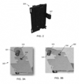
- FIG. 2 illustrates a perspective view of the base 104 of the safety ground terminal apparatus 100 shown in FIG. 1 , in accordance with an embodiment. Note that in the figures illustrated and discussed herein, identical or similar parts are components are indicated by identical reference numerals.
- the view of the base 104 shown in FIG. 2 indicates that the base 104 can also be configured with a tab portion 107 that facilitates connection of the base 104 to other components.
- FIG. 3A illustrates a perspective view of the ground terminal 102 with the circular protruding portion 115 in a first position with respect to the hinge point 116, in accordance with an embodiment.
- FIG. 3B illustrates a perspective view of the ground terminal 102 with the circular protruding portion 115 in a second position with respect to the hinge point 116, in accordance with an embodiment.
- FIG. 4A illustrates an image of the ground terminal 102 assembled to the base 104, in accordance with the present invention.
- FIG. 4B illustrates an image of the base 104 with the ground terminal 102 connected to a common ground, in accordance with an embodiment.
- FIG. 4C illustrates an image of the base 104 with the ground terminal 102 disconnected to the common ground, in accordance with an embodiment. Note that in FIGS. 4B and 4C , the rail 101 is shown with respect to the ground terminal 102, but is not shown in FIG. 4A .
- FIG. 5 illustrates a perspective pictorial view of a configurable safety ground terminal system 200 in which the base 104 is arranged in a manner in which the ground terminal 102 is connected to a common ground, in accordance with an embodiment.
- a PWA (Printed Wiring Assembly) 201 engages a screw 202 that in turn connects to a clinch nut 203 on the PWA 201.
- the circular protruding portion 115 is shown with respect to the hinge point 116 in a first position. As discussed previously, the hinge point 116 allows for movement of the circular protruding portion 115 (which also maintains the screw 114).
- FIG. 6 illustrates a perspective pictorial view of a configurable safety ground terminal system 200 in which the base 104 is arranged in a manner in which the ground terminal 102 is now connected from the common ground, in accordance with an embodiment. That is, as shown in FIG. 6 , the circular protruding portion 115 has now moved from its previous position as shown in FIG. 5 . Thus, FIG. 6 depicts the base 104 with the ground terminal 102 disconnected from the common ground. Note that the configurable safety ground terminal system 200 discussed herein with respect to FIG. 5, FIG. 6 , and FIG. 7 can be implemented in the context of an industrial process control and automation system such as the industrial process control and automation system 400 shown in FIG. 9 .
- FIG. 7 illustrates an image of a ground connection for the configurable safety ground terminal system 200 using a lug and wire device 206, in accordance with an embodiment.
- FIG. 7 depicts a close up view of a portion of the configurable safety ground terminal system 200 shown in FIG. 5 and FIG. 6 .
- the lug and wire device 206 can connect to the screw 202, which facilitates grounding.
- the assembly illustrated with respect to FIGS. 1-7 and as described above provides for an integrated water tight ground connection, which can also enable easy switching between a common ground connection to an isolated ground connection within the mechanical housing of, for example, an FTA designed for marshalling solutions.
- FIG. 8 illustrates a method 300 of operating the safety ground terminal apparatus 100, in accordance with an embodiment.
- the method 300 can be implemented in the context of an industrial process control and automation system such as the industrial process control and automation system 400 shown in FIG. 9 .
- a step or operation can be implemented in which the ground terminal 102 is provided with the hinge point 116, which is connectable to the base 104 of a housing (e.g., chassis/cabinet, equipment rack etc.) via a rail 101.
- a common ground connection and/or an isolated ground connection can be provided.
- a step or operation can be implemented for switching the ground terminal 102 between the aforementioned common ground connection or the isolated ground connection.
- the ground terminal 102 and the hinge point that 116 are connectable to the base 104 of the housing via the rail 101 in an arrangement that allows for disconnection from the common ground connection when the isolated ground connection is required and without compromising electrical contact.
- the switching between the common ground connection or the isolated ground connection can be achieved without any additional parts assembled.
- the use of method 300 can facilitate a watertight ground connection irrespective of any ground connection requirement.
- FIG. 9 illustrates an example industrial process control and automation system 400, in accordance with an embodiment.
- the industrial process control and automation system 400 can include various components that can facilitate production or processing of at least one product or other material.
- the industrial process control and automation system 400 can be used to facilitate control or monitoring of components in one or multiple industrial plants.
- Each plant represents one or more processing facilities (or one or more portions thereof), such as one or more manufacturing facilities for producing at least one product or other material.
- each plant may implement one or more industrial processes and can individually or collectively be referred to as a process system.
- a process system generally represents any system or portion thereof configured to process one or more products or other materials or energy in different forms in some manner.
- the industrial process control and automation system 400 can include one or more sensors 402a and one or more actuators 402b.
- the sensors 402a and actuators 402b represent components in a process system that may perform any of a wide variety of functions.
- the sensors 402a could measure a wide variety of characteristics in the process system, such as temperature, pressure, or flow rate.
- the actuators 402b could alter a wide variety of characteristics in the process system.
- Each of the sensors 402a can include any suitable structure for measuring one or more characteristics in a process system.
- Each of the actuators 402b can include any suitable structure for operating on or affecting one or more conditions in a process system.
- At least one I/O module 1404 can be coupled to the sensors 402a and actuators 402b.
- the I/O modules 104 facilitate interactions with the sensors 402a, actuators 402b, or other field devices.
- an I/O module 404 could be used to receive one or more analog inputs (AIs), digital inputs (DIs), digital input sequences of events (DISOEs), pulse accumulator inputs (PIs), or other inputs from one or more field devices.
- An I/O module 104 could also be used to provide one or more analog outputs (AOs), digital outputs (DOs), or other outputs to one or more field devices.
- the interactions with one or more field devices could occur through at least one (or more) field termination assembly (FTA) 414.
- Each I/O module 404 can include any suitable structure(s) for receiving one or more input signals from or providing one or more output signals to one or more field devices.
- the industrial process control and automation system 400 can also include various controllers 406.
- the controllers 406 can be used in the industrial process control and automation system 400 to perform various functions in order to control one or more industrial processes.
- a first set of controllers 406 may use measurements from one or more sensors 402a to control the operation of one or more actuators 402b. These controllers 406 could interact with the sensors 402a, actuators 402b, and other field devices via the I/O modules 404.
- a second set of controllers 406 could be used to optimize the control logic or other operations performed by the first set of controllers.
- a third set of controllers 406 could be used to perform additional functions. It is also possible that one set of controllers could be in a stand-by or load-sharing mode to improve overall availability of the system.
- Controllers 406 may be arranged hierarchically in a system. For example, different controllers 406 could be used to control individual actuators, collections of actuators forming machines, collections of machines forming units, collections of units forming plants, and collections of plants forming an enterprise.
- the controllers 406 in different hierarchical levels can communicate via one or more networks 408 and associated switches, firewalls, and other components.
- Each controller 406 can include any suitable structure for controlling one or more aspects of an industrial process. At least some of the controllers 406 could, for example, represent proportional-integral-derivative (PID) controllers or multivariable controllers, such as Robust Multivariable Predictive Control Technology (RMPCT) controllers or other types of controllers implementing model predictive control (MPC) or other advanced predictive control. As a particular example, each controller 406 could represent a computing device running a real-time operating system, a WINDOWS operating system, or other operating system.
- PID proportional-integral-derivative
- RPCT Robust Multivariable Predictive Control Technology
- MPC model predictive control
- each controller 406 could represent a computing device running a real-time operating system, a WINDOWS operating system, or other operating system.
- the one or more networks 408 can couple the controllers 406 and other devices in the industrial process control and automation system 400.
- the network 408 can facilitate the transport of information between components.
- the network 408 can represent any suitable network or a combination of networks.
- the network 408 can represent at least one Ethernet network.
- the network 408 may be implemented as a wireless communications network (e.g., a cellular communication network, a WiFi network, a HART (Highway Addressable Remote Transducer Protocol), and so on).
- Operator access to and interaction with the controllers 406 and other components of the industrial process control and automation system 400 can occur via various operator stations 410.
- Each operator station 410 could be used to provide information to an operator and receive information from an operator.
- each operator station 410 could provide information identifying a current state of an industrial process to an operator, such as values of various process variables and warnings, alarms, or other states associated with the industrial process.
- Each operator station 410 can also receive information affecting how the industrial process may be controlled, such as by receiving setpoints for process variables controlled by the controllers 406 or other information that can alerter or affect how the controllers 406 can control the industrial process.
- Each operator station 410 can include any suitable structure for displaying information to and interacting with an operator.
- Each control room 412 can include any number of operator stations 410 in any suitable arrangement.
- multiple control rooms 412 can be used to control an industrial plant, such as when each control room 412 contains operator stations 410 used to manage a discrete part of the industrial plant.
- the various controllers 406 and operator stations 410 shown in FIG. 9 may represent computing devices.
- each of the controllers and operator stations could include one or more processing devices, such as one or more microprocessors, microcontrollers, digital signal processors (DSPs), field programmable gate arrays (FPGAs), application specific integrated circuits (ASICs), or discrete circuitry.
- Each of the controllers 406 and operator stations 410 could also include one or more memories for storing instructions and data used, generated, or collected by the processing device(s), such as a random access memory, read only memory, Flash memory, optical disc, hard drive, or any other suitable volatile or non-volatile storage device(s).
- Each of the controllers 406 and operator stations 410 could further include at least one network interface, such as one or more Ethernet interfaces or wireless transceivers.
- I/O channels can be used to connect controllers (such as the controllers 406) and field devices (such as the sensors 402a and actuators 402b).
- the I/O modules 404 or other devices can support I/O channels of various types, including AIs, DIs, DISOEs, PIs, AOs, or DOs.
- I/O channel types can be characterized by different inputs, outputs, voltages, currents, and configurations.
- a universal I/O (UIO) channel can be a specialized I/O channel that can be reconfigurable to operate as any of multiple I/O channel types.
- At least one field termination assembly 414 can be used in the industrial process control and automation system 400 or other systems.
- Each field termination assembly 414 can include one or more slots configured to receive one or more adaptor modules for one or more I/O channels, such as sixteen adaptor modules for sixteen I/O channels (although other numbers of adaptor modules and I/O channels can be supported).
- Each adaptor module can perform one or more functions related to I/O signals, such as signal conditioning, energy limiting, galvanic isolation, or protection (or any combination thereof).
- the adaptor modules can operate independently, meaning each adaptor module can perform its function(s) for its I/O channel regardless of whether other adaptor modules are present or what those other adaptor modules are doing.
- the slots of a field termination assembly 414 may be universal; meaning different types of adaptor modules can be inserted into the slots of the field termination assembly 414.
- This may allow, for example, different adaptor modules to be designed for different types of I/O channels, such as different adaptor modules for AIs, DIs, DISOEs, PIs, AOs, and DOs.
- This may also allow different adaptor modules supporting different types of signal conditioning, intrinsic safety, galvanic isolation, protection, or other hardware functions to be designed.
- any suitable adaptor modules can be used in a field termination assembly 414, and the field termination assembly 414 can include one or multiple types of adaptor modules.
- the embodiments discussed herein offer a number of solutions.
- the disclosed approach can provide flexibility to the technicians to easily and quickly switch between the common ground termination or the isolated ground connection.
- a watertight ground connection can be implemented irrespective of the type of ground connection requirement.
- This approach can also meet all necessary certification and compliance needs, while reducing lengthy assembly time. This approach also may not impact the rest of the design, tooling and product aesthetics. Changes may also not be required with respect to standard wiring practices that many project teams follow today.
Landscapes
- Engineering & Computer Science (AREA)
- Automation & Control Theory (AREA)
- Physics & Mathematics (AREA)
- General Physics & Mathematics (AREA)
- Microelectronics & Electronic Packaging (AREA)
- Connections Arranged To Contact A Plurality Of Conductors (AREA)
- Connector Housings Or Holding Contact Members (AREA)
Claims (10)
- Sicherheits-Erdungsklemmenvorrichtung (100), umfassend:eine Schiene (101);eine Basis (104) eines Gehäuses; undeine Erdungsklemme (102), die an der Basis (104) angebracht ist und zum Umschalten zwischen einer gemeinsamen Erdungsverbindung oder einer isolierten Erdungsverbindung betätigbar ist, wobei in der gemeinsamen Erdungsverbindung die Erdungsklemme (102) mit der Schiene (101) verbunden ist und die Erdungsklemme (102) in der isolierten Erdungsverbindung von der Schiene (101) getrennt ist;wobei die Erdungsklemme (102) einen Gelenkpunkt (116) umfasst, der mittels der Schiene (101) mit der Basis (104) des Gehäuses in einer Anordnung verbindbar ist, die eine Trennung von der gemeinsamen Erdungsverbindung ermöglicht, wenn die isolierte Erdungsverbindung erforderlich ist, und ohne Beeinträchtigung des elektrischen Kontakts,wobei die Basis (104) so angeordnet ist, dass der Gelenkpunkt (116) eine Bewegung eines kreisförmigen vorstehenden Abschnitts (115) ermöglicht, um eine Schraube (114) zu halten, um die Erdungsklemme (102) mit der gemeinsamen Erdungsverbindung zu verbinden,
- Sicherheits-Erdungsklemmenvorrichtung nach Anspruch 1, wobei die Schiene (101) eine DIN-Schiene umfasst.
- Sicherheits-Erdungsklemmenvorrichtung nach Anspruch 1, wobei die Erdungsklemme (102) unabhängig von der Art der Erdungsverbindungsanforderung eine wasserdichte Erdungsverbindung bereitstellt.
- Sicherheits-Erdungsklemmenvorrichtung nach Anspruch 1, wobei das Gehäuse einen Schrank zur Wartung elektrischer Ausrüstung umfasst.
- Sicherheits-Erdungsklemmenvorrichtung nach Anspruch 1, wobei das Gehäuse ein Gestell umfasst.
- Sicherheits-Erdungsklemmenvorrichtung nach Anspruch 1, die ferner einen separaten Erdungsdraht mit einer Öse (206) umfasst, der mittels einer Klammerbefestigeranordnung in einer durch das Gehäuse gehaltenen Leiterplatte mit einer gedruckten Drahtanordnung verbindbar ist.
- System, umfassend:eine Erdungsanordnung, die eine Mehrzahl von Erdungsverbindungen umfasst; unddie Sicherheits-Erdungsklemmenvorrichtung nach den Ansprüchen 1 bis 6.
- System nach Anspruch 7, wobei die Erdungsanordnung sicherbar ist, um ein versehentliches Umschalten der mindestens einen Erdungsverbindung unter der Mehrzahl von Erdungsverbindungen zu verhindern, wenn das System aktiv ist.
- System nach Anspruch 7, wobei die Erdungsverbindung unabhängig von der Art der Erdungsverbindungsanforderung eine wasserdichte Erdungsverbindung bereitstellt.
- Verfahren zum Betätigen einer Sicherheits-Erdungsklemmenvorrichtung, umfassend:Umschalten einer Erdungsklemme (102) zwischen einer gemeinsamen Erdungsverbindung oder einer isolierten Erdungsverbindung, wobei in der gemeinsamen Erdungsverbindung die Erdungsklemme (102) mit einer Schiene (101) verbunden ist und die Erdungsklemme (102) in der isolierten Erdungsverbindung von der Schiene (101) getrennt ist;wobei die Erdungsklemme (102) an einer Basis (104) eines Gehäuses montiert ist, und einen Gelenkpunkt (116) umfasst, der mittels der Schiene (101) mit der Basis (104) des Gehäuses in einer Anordnung verbindbar ist, die eine Trennung von der gemeinsamen Erdungsverbindung ermöglicht, wenn die isolierte Erdungsverbindung erforderlich ist, und ohne Beeinträchtigung des elektrischen Kontakts,wobei die Basis (104) so angeordnet ist, dass der Gelenkpunkt (116) eine Bewegung eines kreisförmigen vorstehenden Abschnitts (115) ermöglicht, um eine Schraube (114) zu halten, um die Erdungsklemme (102) mit der gemeinsamen Erdungsverbindung zu verbinden.
Applications Claiming Priority (2)
| Application Number | Priority Date | Filing Date | Title |
|---|---|---|---|
| US202063042149P | 2020-06-22 | 2020-06-22 | |
| US17/216,888 US11611163B2 (en) | 2020-06-22 | 2021-03-30 | Configurable safety ground terminals for industrial applications |
Publications (2)
| Publication Number | Publication Date |
|---|---|
| EP3930433A1 EP3930433A1 (de) | 2021-12-29 |
| EP3930433B1 true EP3930433B1 (de) | 2023-12-06 |
Family
ID=76325353
Family Applications (1)
| Application Number | Title | Priority Date | Filing Date |
|---|---|---|---|
| EP21177860.0A Active EP3930433B1 (de) | 2020-06-22 | 2021-06-04 | Erdungsklemmen mit konfigurierbarer sicherheit für industrielle anwendungen |
Country Status (3)
| Country | Link |
|---|---|
| US (1) | US11611163B2 (de) |
| EP (1) | EP3930433B1 (de) |
| CN (1) | CN113904131B (de) |
Cited By (1)
| Publication number | Priority date | Publication date | Assignee | Title |
|---|---|---|---|---|
| WO2025228849A1 (de) * | 2024-04-30 | 2025-11-06 | Murrelektronik Gmbh | Automatisierungsvorrichtung mit einer umschaltvorrichtung |
Citations (1)
| Publication number | Priority date | Publication date | Assignee | Title |
|---|---|---|---|---|
| EP2483977B1 (de) * | 2009-09-29 | 2014-11-12 | Panduit Corp. | Tragschienen-adapter mit erdungsvorrichtung |
Family Cites Families (13)
| Publication number | Priority date | Publication date | Assignee | Title |
|---|---|---|---|---|
| US6008985A (en) | 1995-11-20 | 1999-12-28 | The Foxboro Company | Industrial field controlling device with controller and expansion modules |
| US20070100472A1 (en) | 2005-10-31 | 2007-05-03 | Honeywell International Inc. | System and method for creating serial interface protocols in a process control environment |
| US8570922B2 (en) | 2007-04-13 | 2013-10-29 | Hart Communication Foundation | Efficient addressing in wireless hart protocol |
| US8451809B2 (en) | 2007-04-13 | 2013-05-28 | Hart Communication Foundation | Wireless gateway in a process control environment supporting a wireless communication protocol |
| TWM377827U (en) * | 2008-07-22 | 2010-04-01 | Molex Inc | Ground termination with dampened resonance |
| US8451176B2 (en) | 2009-06-11 | 2013-05-28 | Honeywell International Inc. | Method for achieving intrinsic safety compliance in wireless devices using isolated overlapping grounds and related apparatus |
| US8873241B2 (en) | 2011-05-23 | 2014-10-28 | Honeywell International Inc. | Intrinsically safe serviceable transmitter apparatus and method |
| JP5896959B2 (ja) * | 2013-06-14 | 2016-03-30 | ヒロセ電機株式会社 | 回路基板用電気コネクタおよび電気コネクタ実装体 |
| CN103354190B (zh) | 2013-06-26 | 2017-03-22 | 国家电网公司 | 隔离接地开关装置及使用该装置的固体绝缘开关 |
| US10296515B2 (en) | 2016-06-09 | 2019-05-21 | Honeywell International Inc. | Engineering data collection from control and instrumentation systems |
| US10354343B2 (en) | 2016-11-14 | 2019-07-16 | Schneider Electric Systems Usa, Inc. | Automated process control hardware engineering using schema-represented requirements |
| US10790609B2 (en) * | 2018-10-22 | 2020-09-29 | Honeywell International Inc. | Field termination assembly supporting use of mistake-proof keys |
| US11445623B2 (en) * | 2019-01-31 | 2022-09-13 | Honeywell International Inc. | Field termination assembly (FTA) with quick mount |
-
2021
- 2021-03-30 US US17/216,888 patent/US11611163B2/en active Active
- 2021-06-04 EP EP21177860.0A patent/EP3930433B1/de active Active
- 2021-06-15 CN CN202110663367.1A patent/CN113904131B/zh active Active
Patent Citations (1)
| Publication number | Priority date | Publication date | Assignee | Title |
|---|---|---|---|---|
| EP2483977B1 (de) * | 2009-09-29 | 2014-11-12 | Panduit Corp. | Tragschienen-adapter mit erdungsvorrichtung |
Cited By (1)
| Publication number | Priority date | Publication date | Assignee | Title |
|---|---|---|---|---|
| WO2025228849A1 (de) * | 2024-04-30 | 2025-11-06 | Murrelektronik Gmbh | Automatisierungsvorrichtung mit einer umschaltvorrichtung |
Also Published As
| Publication number | Publication date |
|---|---|
| CN113904131B (zh) | 2026-03-24 |
| EP3930433A1 (de) | 2021-12-29 |
| US20210399445A1 (en) | 2021-12-23 |
| US11611163B2 (en) | 2023-03-21 |
| CN113904131A (zh) | 2022-01-07 |
Similar Documents
| Publication | Publication Date | Title |
|---|---|---|
| US8553395B2 (en) | Motor control center network connectivity method and system | |
| EP2421344B1 (de) | Eingabe-/Ausgabevorrichtungen mit rekonfigurierbarer Funktion | |
| EP2227845B1 (de) | Schaltfeld mit ups und horizontalen sammelschienen | |
| US9104383B2 (en) | Programmable controller component with assembly alignment features | |
| EP3104237B1 (de) | Scheiben-i/o-feldenergiebusschutzschalter | |
| US20160259752A1 (en) | Universal I/O Signal Interposer System | |
| US9425603B2 (en) | Bus plug apparatus using multiple interconnected enclosures | |
| US11611163B2 (en) | Configurable safety ground terminals for industrial applications | |
| EP1611777B1 (de) | Niederspannungsmodul | |
| SG178644A1 (en) | Integral cable guide for electronic module | |
| KR20170082713A (ko) | Plc기반 필드버스 실습장비 | |
| US20060234526A1 (en) | Automation system | |
| US8116070B2 (en) | Control and switchgear cabinet | |
| EP3273563B1 (de) | Intelligenter stromabgriff zur stromversorgung und kommunikation in industriellen automatisierungsanwendungen | |
| US12463417B2 (en) | Electrical circuit breaker for protecting energy distribution in an industrial plant | |
| US12348110B2 (en) | Systems and methods for motor control center bus bars | |
| CN221351693U (zh) | 一种电机寿命智能监测装置 | |
| Lakshmi et al. | Scada Based Online Circuit Breaker Monitoring System | |
| DE102009056213A1 (de) | Ethernet-Koppelgerät für die Gebäudeautomation | |
| US20120249268A1 (en) | Industrial process terminated communication system | |
| Blair et al. | Integrating networks into motor control systems | |
| CN117666456A (zh) | 智能输送控制器及控制方法 | |
| Vavra et al. | 2015 Finalists Product of the Year | |
| WO2025228849A1 (de) | Automatisierungsvorrichtung mit einer umschaltvorrichtung |
Legal Events
| Date | Code | Title | Description |
|---|---|---|---|
| PUAI | Public reference made under article 153(3) epc to a published international application that has entered the european phase |
Free format text: ORIGINAL CODE: 0009012 |
|
| STAA | Information on the status of an ep patent application or granted ep patent |
Free format text: STATUS: REQUEST FOR EXAMINATION WAS MADE |
|
| 17P | Request for examination filed |
Effective date: 20210604 |
|
| AK | Designated contracting states |
Kind code of ref document: A1 Designated state(s): AL AT BE BG CH CY CZ DE DK EE ES FI FR GB GR HR HU IE IS IT LI LT LU LV MC MK MT NL NO PL PT RO RS SE SI SK SM TR |
|
| B565 | Issuance of search results under rule 164(2) epc |
Effective date: 20211118 |
|
| P01 | Opt-out of the competence of the unified patent court (upc) registered |
Effective date: 20230414 |
|
| GRAP | Despatch of communication of intention to grant a patent |
Free format text: ORIGINAL CODE: EPIDOSNIGR1 |
|
| STAA | Information on the status of an ep patent application or granted ep patent |
Free format text: STATUS: GRANT OF PATENT IS INTENDED |
|
| RIC1 | Information provided on ipc code assigned before grant |
Ipc: H01R 4/64 20060101ALI20230705BHEP Ipc: H01R 9/26 20060101ALI20230705BHEP Ipc: H05K 7/14 20060101AFI20230705BHEP |
|
| INTG | Intention to grant announced |
Effective date: 20230731 |
|
| GRAS | Grant fee paid |
Free format text: ORIGINAL CODE: EPIDOSNIGR3 |
|
| GRAA | (expected) grant |
Free format text: ORIGINAL CODE: 0009210 |
|
| STAA | Information on the status of an ep patent application or granted ep patent |
Free format text: STATUS: THE PATENT HAS BEEN GRANTED |
|
| AK | Designated contracting states |
Kind code of ref document: B1 Designated state(s): AL AT BE BG CH CY CZ DE DK EE ES FI FR GB GR HR HU IE IS IT LI LT LU LV MC MK MT NL NO PL PT RO RS SE SI SK SM TR |
|
| REG | Reference to a national code |
Ref country code: GB Ref legal event code: FG4D |
|
| REG | Reference to a national code |
Ref country code: CH Ref legal event code: EP |
|
| REG | Reference to a national code |
Ref country code: DE Ref legal event code: R096 Ref document number: 602021007409 Country of ref document: DE |
|
| REG | Reference to a national code |
Ref country code: IE Ref legal event code: FG4D |
|
| REG | Reference to a national code |
Ref country code: LT Ref legal event code: MG9D |
|
| PG25 | Lapsed in a contracting state [announced via postgrant information from national office to epo] |
Ref country code: GR Free format text: LAPSE BECAUSE OF FAILURE TO SUBMIT A TRANSLATION OF THE DESCRIPTION OR TO PAY THE FEE WITHIN THE PRESCRIBED TIME-LIMIT Effective date: 20240307 |
|
| REG | Reference to a national code |
Ref country code: NL Ref legal event code: MP Effective date: 20231206 |
|
| PG25 | Lapsed in a contracting state [announced via postgrant information from national office to epo] |
Ref country code: LT Free format text: LAPSE BECAUSE OF FAILURE TO SUBMIT A TRANSLATION OF THE DESCRIPTION OR TO PAY THE FEE WITHIN THE PRESCRIBED TIME-LIMIT Effective date: 20231206 |
|
| PG25 | Lapsed in a contracting state [announced via postgrant information from national office to epo] |
Ref country code: ES Free format text: LAPSE BECAUSE OF FAILURE TO SUBMIT A TRANSLATION OF THE DESCRIPTION OR TO PAY THE FEE WITHIN THE PRESCRIBED TIME-LIMIT Effective date: 20231206 |
|
| PG25 | Lapsed in a contracting state [announced via postgrant information from national office to epo] |
Ref country code: LT Free format text: LAPSE BECAUSE OF FAILURE TO SUBMIT A TRANSLATION OF THE DESCRIPTION OR TO PAY THE FEE WITHIN THE PRESCRIBED TIME-LIMIT Effective date: 20231206 Ref country code: GR Free format text: LAPSE BECAUSE OF FAILURE TO SUBMIT A TRANSLATION OF THE DESCRIPTION OR TO PAY THE FEE WITHIN THE PRESCRIBED TIME-LIMIT Effective date: 20240307 Ref country code: ES Free format text: LAPSE BECAUSE OF FAILURE TO SUBMIT A TRANSLATION OF THE DESCRIPTION OR TO PAY THE FEE WITHIN THE PRESCRIBED TIME-LIMIT Effective date: 20231206 Ref country code: BG Free format text: LAPSE BECAUSE OF FAILURE TO SUBMIT A TRANSLATION OF THE DESCRIPTION OR TO PAY THE FEE WITHIN THE PRESCRIBED TIME-LIMIT Effective date: 20240306 |
|
| REG | Reference to a national code |
Ref country code: AT Ref legal event code: MK05 Ref document number: 1639595 Country of ref document: AT Kind code of ref document: T Effective date: 20231206 |
|
| PG25 | Lapsed in a contracting state [announced via postgrant information from national office to epo] |
Ref country code: NL Free format text: LAPSE BECAUSE OF FAILURE TO SUBMIT A TRANSLATION OF THE DESCRIPTION OR TO PAY THE FEE WITHIN THE PRESCRIBED TIME-LIMIT Effective date: 20231206 |
|
| PG25 | Lapsed in a contracting state [announced via postgrant information from national office to epo] |
Ref country code: SE Free format text: LAPSE BECAUSE OF FAILURE TO SUBMIT A TRANSLATION OF THE DESCRIPTION OR TO PAY THE FEE WITHIN THE PRESCRIBED TIME-LIMIT Effective date: 20231206 Ref country code: RS Free format text: LAPSE BECAUSE OF FAILURE TO SUBMIT A TRANSLATION OF THE DESCRIPTION OR TO PAY THE FEE WITHIN THE PRESCRIBED TIME-LIMIT Effective date: 20231206 Ref country code: NO Free format text: LAPSE BECAUSE OF FAILURE TO SUBMIT A TRANSLATION OF THE DESCRIPTION OR TO PAY THE FEE WITHIN THE PRESCRIBED TIME-LIMIT Effective date: 20240306 Ref country code: NL Free format text: LAPSE BECAUSE OF FAILURE TO SUBMIT A TRANSLATION OF THE DESCRIPTION OR TO PAY THE FEE WITHIN THE PRESCRIBED TIME-LIMIT Effective date: 20231206 Ref country code: LV Free format text: LAPSE BECAUSE OF FAILURE TO SUBMIT A TRANSLATION OF THE DESCRIPTION OR TO PAY THE FEE WITHIN THE PRESCRIBED TIME-LIMIT Effective date: 20231206 Ref country code: HR Free format text: LAPSE BECAUSE OF FAILURE TO SUBMIT A TRANSLATION OF THE DESCRIPTION OR TO PAY THE FEE WITHIN THE PRESCRIBED TIME-LIMIT Effective date: 20231206 |
|
| PG25 | Lapsed in a contracting state [announced via postgrant information from national office to epo] |
Ref country code: IS Free format text: LAPSE BECAUSE OF FAILURE TO SUBMIT A TRANSLATION OF THE DESCRIPTION OR TO PAY THE FEE WITHIN THE PRESCRIBED TIME-LIMIT Effective date: 20240406 |
|
| PG25 | Lapsed in a contracting state [announced via postgrant information from national office to epo] |
Ref country code: CZ Free format text: LAPSE BECAUSE OF FAILURE TO SUBMIT A TRANSLATION OF THE DESCRIPTION OR TO PAY THE FEE WITHIN THE PRESCRIBED TIME-LIMIT Effective date: 20231206 Ref country code: AT Free format text: LAPSE BECAUSE OF FAILURE TO SUBMIT A TRANSLATION OF THE DESCRIPTION OR TO PAY THE FEE WITHIN THE PRESCRIBED TIME-LIMIT Effective date: 20231206 |
|
| PG25 | Lapsed in a contracting state [announced via postgrant information from national office to epo] |
Ref country code: SK Free format text: LAPSE BECAUSE OF FAILURE TO SUBMIT A TRANSLATION OF THE DESCRIPTION OR TO PAY THE FEE WITHIN THE PRESCRIBED TIME-LIMIT Effective date: 20231206 |
|
| PG25 | Lapsed in a contracting state [announced via postgrant information from national office to epo] |
Ref country code: SM Free format text: LAPSE BECAUSE OF FAILURE TO SUBMIT A TRANSLATION OF THE DESCRIPTION OR TO PAY THE FEE WITHIN THE PRESCRIBED TIME-LIMIT Effective date: 20231206 Ref country code: SK Free format text: LAPSE BECAUSE OF FAILURE TO SUBMIT A TRANSLATION OF THE DESCRIPTION OR TO PAY THE FEE WITHIN THE PRESCRIBED TIME-LIMIT Effective date: 20231206 Ref country code: RO Free format text: LAPSE BECAUSE OF FAILURE TO SUBMIT A TRANSLATION OF THE DESCRIPTION OR TO PAY THE FEE WITHIN THE PRESCRIBED TIME-LIMIT Effective date: 20231206 Ref country code: IT Free format text: LAPSE BECAUSE OF FAILURE TO SUBMIT A TRANSLATION OF THE DESCRIPTION OR TO PAY THE FEE WITHIN THE PRESCRIBED TIME-LIMIT Effective date: 20231206 Ref country code: IS Free format text: LAPSE BECAUSE OF FAILURE TO SUBMIT A TRANSLATION OF THE DESCRIPTION OR TO PAY THE FEE WITHIN THE PRESCRIBED TIME-LIMIT Effective date: 20240406 Ref country code: EE Free format text: LAPSE BECAUSE OF FAILURE TO SUBMIT A TRANSLATION OF THE DESCRIPTION OR TO PAY THE FEE WITHIN THE PRESCRIBED TIME-LIMIT Effective date: 20231206 Ref country code: CZ Free format text: LAPSE BECAUSE OF FAILURE TO SUBMIT A TRANSLATION OF THE DESCRIPTION OR TO PAY THE FEE WITHIN THE PRESCRIBED TIME-LIMIT Effective date: 20231206 Ref country code: AT Free format text: LAPSE BECAUSE OF FAILURE TO SUBMIT A TRANSLATION OF THE DESCRIPTION OR TO PAY THE FEE WITHIN THE PRESCRIBED TIME-LIMIT Effective date: 20231206 |
|
| PG25 | Lapsed in a contracting state [announced via postgrant information from national office to epo] |
Ref country code: PT Free format text: LAPSE BECAUSE OF FAILURE TO SUBMIT A TRANSLATION OF THE DESCRIPTION OR TO PAY THE FEE WITHIN THE PRESCRIBED TIME-LIMIT Effective date: 20240408 Ref country code: PL Free format text: LAPSE BECAUSE OF FAILURE TO SUBMIT A TRANSLATION OF THE DESCRIPTION OR TO PAY THE FEE WITHIN THE PRESCRIBED TIME-LIMIT Effective date: 20231206 |
|
| PG25 | Lapsed in a contracting state [announced via postgrant information from national office to epo] |
Ref country code: PT Free format text: LAPSE BECAUSE OF FAILURE TO SUBMIT A TRANSLATION OF THE DESCRIPTION OR TO PAY THE FEE WITHIN THE PRESCRIBED TIME-LIMIT Effective date: 20240408 Ref country code: PL Free format text: LAPSE BECAUSE OF FAILURE TO SUBMIT A TRANSLATION OF THE DESCRIPTION OR TO PAY THE FEE WITHIN THE PRESCRIBED TIME-LIMIT Effective date: 20231206 |
|
| REG | Reference to a national code |
Ref country code: DE Ref legal event code: R097 Ref document number: 602021007409 Country of ref document: DE |
|
| PG25 | Lapsed in a contracting state [announced via postgrant information from national office to epo] |
Ref country code: DK Free format text: LAPSE BECAUSE OF FAILURE TO SUBMIT A TRANSLATION OF THE DESCRIPTION OR TO PAY THE FEE WITHIN THE PRESCRIBED TIME-LIMIT Effective date: 20231206 |
|
| PLBE | No opposition filed within time limit |
Free format text: ORIGINAL CODE: 0009261 |
|
| STAA | Information on the status of an ep patent application or granted ep patent |
Free format text: STATUS: NO OPPOSITION FILED WITHIN TIME LIMIT |
|
| PG25 | Lapsed in a contracting state [announced via postgrant information from national office to epo] |
Ref country code: SI Free format text: LAPSE BECAUSE OF FAILURE TO SUBMIT A TRANSLATION OF THE DESCRIPTION OR TO PAY THE FEE WITHIN THE PRESCRIBED TIME-LIMIT Effective date: 20231206 |
|
| PG25 | Lapsed in a contracting state [announced via postgrant information from national office to epo] |
Ref country code: SI Free format text: LAPSE BECAUSE OF FAILURE TO SUBMIT A TRANSLATION OF THE DESCRIPTION OR TO PAY THE FEE WITHIN THE PRESCRIBED TIME-LIMIT Effective date: 20231206 Ref country code: DK Free format text: LAPSE BECAUSE OF FAILURE TO SUBMIT A TRANSLATION OF THE DESCRIPTION OR TO PAY THE FEE WITHIN THE PRESCRIBED TIME-LIMIT Effective date: 20231206 |
|
| 26N | No opposition filed |
Effective date: 20240909 |
|
| PG25 | Lapsed in a contracting state [announced via postgrant information from national office to epo] |
Ref country code: MC Free format text: LAPSE BECAUSE OF FAILURE TO SUBMIT A TRANSLATION OF THE DESCRIPTION OR TO PAY THE FEE WITHIN THE PRESCRIBED TIME-LIMIT Effective date: 20231206 |
|
| REG | Reference to a national code |
Ref country code: CH Ref legal event code: PL |
|
| PG25 | Lapsed in a contracting state [announced via postgrant information from national office to epo] |
Ref country code: LU Free format text: LAPSE BECAUSE OF NON-PAYMENT OF DUE FEES Effective date: 20240604 |
|
| PG25 | Lapsed in a contracting state [announced via postgrant information from national office to epo] |
Ref country code: IE Free format text: LAPSE BECAUSE OF NON-PAYMENT OF DUE FEES Effective date: 20240604 |
|
| PG25 | Lapsed in a contracting state [announced via postgrant information from national office to epo] |
Ref country code: CH Free format text: LAPSE BECAUSE OF NON-PAYMENT OF DUE FEES Effective date: 20240630 Ref country code: BE Free format text: LAPSE BECAUSE OF NON-PAYMENT OF DUE FEES Effective date: 20240630 |
|
| REG | Reference to a national code |
Ref country code: BE Ref legal event code: MM Effective date: 20240630 |
|
| PGFP | Annual fee paid to national office [announced via postgrant information from national office to epo] |
Ref country code: DE Payment date: 20250626 Year of fee payment: 5 |
|
| PGFP | Annual fee paid to national office [announced via postgrant information from national office to epo] |
Ref country code: GB Payment date: 20250617 Year of fee payment: 5 |
|
| PGFP | Annual fee paid to national office [announced via postgrant information from national office to epo] |
Ref country code: FR Payment date: 20250624 Year of fee payment: 5 |
|
| PG25 | Lapsed in a contracting state [announced via postgrant information from national office to epo] |
Ref country code: FI Free format text: LAPSE BECAUSE OF FAILURE TO SUBMIT A TRANSLATION OF THE DESCRIPTION OR TO PAY THE FEE WITHIN THE PRESCRIBED TIME-LIMIT Effective date: 20231207 |
|
| PG25 | Lapsed in a contracting state [announced via postgrant information from national office to epo] |
Ref country code: CY Free format text: LAPSE BECAUSE OF FAILURE TO SUBMIT A TRANSLATION OF THE DESCRIPTION OR TO PAY THE FEE WITHIN THE PRESCRIBED TIME-LIMIT; INVALID AB INITIO Effective date: 20210604 |
|
| PG25 | Lapsed in a contracting state [announced via postgrant information from national office to epo] |
Ref country code: HU Free format text: LAPSE BECAUSE OF FAILURE TO SUBMIT A TRANSLATION OF THE DESCRIPTION OR TO PAY THE FEE WITHIN THE PRESCRIBED TIME-LIMIT; INVALID AB INITIO Effective date: 20210604 |