EP3930424A1 - Support device for an induction coil - Google Patents
Support device for an induction coil Download PDFInfo
- Publication number
- EP3930424A1 EP3930424A1 EP20182407.5A EP20182407A EP3930424A1 EP 3930424 A1 EP3930424 A1 EP 3930424A1 EP 20182407 A EP20182407 A EP 20182407A EP 3930424 A1 EP3930424 A1 EP 3930424A1
- Authority
- EP
- European Patent Office
- Prior art keywords
- support device
- electrically conductive
- base plate
- coil
- induction
- Prior art date
- Legal status (The legal status is an assumption and is not a legal conclusion. Google has not performed a legal analysis and makes no representation as to the accuracy of the status listed.)
- Granted
Links
Images


Classifications
-
- H—ELECTRICITY
- H05—ELECTRIC TECHNIQUES NOT OTHERWISE PROVIDED FOR
- H05B—ELECTRIC HEATING; ELECTRIC LIGHT SOURCES NOT OTHERWISE PROVIDED FOR; CIRCUIT ARRANGEMENTS FOR ELECTRIC LIGHT SOURCES, IN GENERAL
- H05B6/00—Heating by electric, magnetic or electromagnetic fields
- H05B6/02—Induction heating
- H05B6/10—Induction heating apparatus, other than furnaces, for specific applications
- H05B6/12—Cooking devices
- H05B6/1209—Cooking devices induction cooking plates or the like and devices to be used in combination with them
-
- H—ELECTRICITY
- H05—ELECTRIC TECHNIQUES NOT OTHERWISE PROVIDED FOR
- H05B—ELECTRIC HEATING; ELECTRIC LIGHT SOURCES NOT OTHERWISE PROVIDED FOR; CIRCUIT ARRANGEMENTS FOR ELECTRIC LIGHT SOURCES, IN GENERAL
- H05B6/00—Heating by electric, magnetic or electromagnetic fields
- H05B6/02—Induction heating
- H05B6/10—Induction heating apparatus, other than furnaces, for specific applications
- H05B6/12—Cooking devices
- H05B6/1209—Cooking devices induction cooking plates or the like and devices to be used in combination with them
- H05B6/1245—Cooking devices induction cooking plates or the like and devices to be used in combination with them with special coil arrangements
- H05B6/1254—Cooking devices induction cooking plates or the like and devices to be used in combination with them with special coil arrangements using conductive pieces to direct the induced magnetic field
-
- H—ELECTRICITY
- H05—ELECTRIC TECHNIQUES NOT OTHERWISE PROVIDED FOR
- H05B—ELECTRIC HEATING; ELECTRIC LIGHT SOURCES NOT OTHERWISE PROVIDED FOR; CIRCUIT ARRANGEMENTS FOR ELECTRIC LIGHT SOURCES, IN GENERAL
- H05B2206/00—Aspects relating to heating by electric, magnetic, or electromagnetic fields covered by group H05B6/00
- H05B2206/02—Induction heating
- H05B2206/022—Special supports for the induction coils
-
- Y—GENERAL TAGGING OF NEW TECHNOLOGICAL DEVELOPMENTS; GENERAL TAGGING OF CROSS-SECTIONAL TECHNOLOGIES SPANNING OVER SEVERAL SECTIONS OF THE IPC; TECHNICAL SUBJECTS COVERED BY FORMER USPC CROSS-REFERENCE ART COLLECTIONS [XRACs] AND DIGESTS
- Y02—TECHNOLOGIES OR APPLICATIONS FOR MITIGATION OR ADAPTATION AGAINST CLIMATE CHANGE
- Y02B—CLIMATE CHANGE MITIGATION TECHNOLOGIES RELATED TO BUILDINGS, e.g. HOUSING, HOUSE APPLIANCES OR RELATED END-USER APPLICATIONS
- Y02B40/00—Technologies aiming at improving the efficiency of home appliances, e.g. induction cooking or efficient technologies for refrigerators, freezers or dish washers
Definitions
- the present invention relates to a support device for an induction coil of an induction heating appliance. Further, the present invention relates to an induction coil for an induction heating appliance. Moreover, the present invention relates to an induction heating appliance, in particular an induction cooking appliance, for example an induction cooking hob or an induction cooking oven.
- FIG 5 illustrates a schematic sectional side view of an induction coil 20 according to the prior art.
- the induction coil 20 comprises a metal base plate 18 and a ferrite layer or ferrite elements 16 arranged on said metal base plate 18.
- a winding support layer 22 is arranged on the ferrite elements 16 and supports a coil winding 24.
- a thermal insulating layer 26 is arranged above the coil winding 24.
- an electric insulating layer 28 is arranged above said thermal insulating layer 26.
- a temperature sensor 30 is arranged within a recess of the coil winding 24.
- the metal base plate 18 is provided for supporting the other components of the induction coil 20 on the one hand and acts as magnetic shield for the area beneath said metal base plate 18 on the other hand.
- the metal base plate 18 is made of aluminium.
- the coil winding 24 requires a relative high number of winding turns due to the presence of the metal base plate 18. Further, the interaction of the metal base plate 18 with the magnetic field reduces the energy efficiency of the induction coil 20.
- the object is achieved by the support device for an induction coil according to claim 1.
- a support device for an induction coil of an induction heating appliance wherein:
- the core of the present invention is the electrically conductive and/or magnetic layer applied on the coil base plate made of electrically non-conductive material.
- the coil base plate provides mechanical support, while the electrically conductive and/or magnetic layer acts as electric and/or magnetic shield for the area on the opposite side of a winding of the induction coil.
- This concept allows a thin electrically conductive and/or magnetic layer and a reduced number of winding turns for a given coil inductivity value.
- the support device of the present invention improves the energy efficiency of the induction coil, since the interaction between the thin electrically conductive layer and the magnetic field is reduced.
- the support device may include at least one ferrite element arranged on the electrically conductive and/or magnetic layer and/or directly on the coil base plate.
- the electrically conductive and/or magnetic layer is a metal layer attached on the coil base plate.
- the metal layer is made of non-magnetic material.
- the electrically conductive and/or magnetic layer is an electrically conductive and/or magnetic paint layer applied on the coil base plate.
- the electrically conductive paint layer is made of non-magnetic material.
- the non-magnetic material has lower losses than magnetic material, so that the energy efficiency is higher.
- the electrically conductive layer with non-magnetic properties shields the electric field.
- the electrically conductive layer with non-magnetic properties shields has no effect on the magnetic field.
- an electrically non-conductive layer made of magnetic material can be used to shield the magnetic field.
- the magnetic, but electrically non-conductive, material has lower losses than magnetic and electrically conductive material, so that the energy efficiency is higher.
- the magnetic, but electrically non-conductive, has no effect on the electric field.
- the electrically conductive layer with non-magnetic properties may be evenly distributed on at least one large-area side of the coil base plate.
- the electrically conductive layer with non-magnetic properties may be subdivided into separate parts.
- the magnetic layer with electrically non-conductive may be subdivided into separate parts.
- the separate parts of the electrically conductive and/or magnetic layer and the ferrite elements are arranged side-by-side on the coil base plate.
- the electrically conductive and/or magnetic layer and/or the separate parts of the electrically conductive and/or magnetic layer are electrically floating. Thus, no electrical connections are required. This contributes to low complexity of the support device.
- the electrically conductive and/or magnetic layer and/or the separate parts of the electrically conductive and/or magnetic layer may be connected to an electrical reference point. This in an improvement on EMC emissions.
- the coil base plate is made of plastic, mica, fibre glass compound and/or composite epoxy material.
- the present invention relates to an induction coil for an induction heating appliance, in particular for an induction cooking appliance, preferably for an induction cooking hob or induction cooking oven, wherein the induction coil includes the support device mentioned above.
- the present invention relates to an induction heating appliance, in particular an induction cooking appliance, preferably an induction cooking hob or induction cooking oven, wherein the induction heating appliance comprises at least one support device and/or at least one induction coil described above.
- FIG 1 illustrates a schematic top view of a support device 10 for an induction coil according to a first embodiment of the present invention.
- the support device 10 for the induction coil is provided for an arbitrary induction heating appliance.
- the support device 10 for the induction coil is provided for an induction cooking appliance.
- the support device 10 for the induction coil is provided for an induction cooking hob or an induction cooking oven.
- the support device 10 includes a coil base plate 12 and an electrically conductive layer 14.
- the coil base plate 12 is coated by the electrically conductive layer 14.
- the upper large-area side of the coil base plate 12 is coated by the electrically conductive layer 14.
- the coil base plate 12 is formed as a circular disk.
- the coil base plate 12 is made of at least one electrically nonconducting material.
- the coil base plate 12 is made of plastic, mica, fibre glass compound, composite epoxy material (CEM) and/or the like.
- the electrically conductive layer 14 may be a non-magnetic or magnetic layer.
- the electrically conductive layer 14 is a thin metal layer or a conductive paint layer.
- the support device 10 is provided for supporting winding of the induction coil.
- the coil base plate 12 provides mechanical support, while the electrically conductive layer 14 acts as magnetic shield for the area opposite side of a winding of the induction coil.
- the support device 10 includes ferrite elements 16.
- the ferrite elements 16 are formed as rectangular sheet elements.
- the ferrite elements 16 are arranged on the electrically conductive layer 14.
- eight elongated ferrite elements 16 extend in the radial direction.
- FIG 2 illustrates a schematic sectional side view of the support device 10 for the induction coil according to the first embodiment of the present invention.
- the support device 10 includes the coil base plate 12, the electrically conductive layer 14 and the ferrite elements 16.
- the upper large-area side of the coil base plate 12 is coated by the electrically conductive layer 14 and the ferrite elements 16 are arranged on said electrically conductive layer 14.
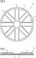
- FIG 3 illustrates a schematic top view of the support device 10 for the induction coil according to a second embodiment of the present invention.
- the support device 10 includes the coil base plate 12, the electrically conductive layer 14 and the ferrite elements 16.
- the coil base plate 12 is formed as circular disk.
- the upper large-area side of the coil base plate 12 is partially coated by the electrically conductive layer 14, wherein said electrically conductive layer 14 is subdivided into separate triangular parts.
- the ferrite elements 16 are formed as elongated rectangular sheet elements, extend in the radial direction and are arranged directly on the coil base plate 12.
- the separate triangular parts of the electrically conductive layer 14 are arranged between two adjacent ferrite elements 16 in each case.
- the electrically conductive layer 14 includes eight separate triangular parts, while the support device 10 includes eight ferrite elements 16.
- the ferrite elements 16 cover the majority of a coil winding 24, so that the magnetic field is efficiently shielded.
- FIG 4 illustrates a schematic sectional side view of the support device 10 for the induction coil according to the second embodiment of the present invention.
- the support device 10 includes the coil base plate 12, the electrically conductive layer 14 and the ferrite elements 16.
- the upper large-area side of the coil base plate 12 is partially coated by the electrically conductive layer 14, while the ferrite elements 16 are directly arranged on said coil base plate 12.
- the electrically conductive layer 14 and the ferrite elements 16 are arranged side-by-side on the coil base plate 12.
- the upper large-area side of the coil base plate 12 is completely or partially, respectively, coated by the electrically conductive layer 14.
- the lower large-area side of the coil base plate 12 may be coated by the electrically conductive layer 14.
- the electrically conductive layer 14 is a non-magnetic thin metal layer. Further, the electrically conductive layer 14 may be a magnetic or non-magnetic conductive paint layer.
- the electrically conductive layer 14 may be electrically either floating or connected to an electrical reference point.
- the coil base plate 12 may includes cut-outs, recesses and/or slots for fixing a coil support or a coil winding.
- FIG 5 illustrates a schematic sectional side view of an induction coil 20 according to the prior art.
- the induction coil 20 comprises a metal base plate 18 and a ferrite layer or the ferrite elements 16 arranged on said metal base plate 18.
- a winding support layer 22 is arranged on the ferrite elements 16 and supports a coil winding 24.
- a thermal insulating layer 26 is arranged above the coil winding 24.
- an electric insulating layer 28 is arranged above said thermal insulating layer 26.
- a temperature sensor 30 is arranged within a recess of the coil winding 24.
- the metal base plate 18 is provided for supporting the other components of the induction coil 20 on the one hand and acts as magnetic shield for the area beneath said metal base plate 18 on the other hand.
- the metal base plate 18 is made of aluminium.
- the coil winding 24 requires a lot of winding turns. Further, the interaction of the metal base plate 18 with the magnetic field reduces the energy efficiency of the induction coil 20.
- the support device 10 according to the present invention with the thin electrically conductive layer 14 allows a decreased number of winding turns for a given coil inductivity value. Further, the support device 10 of the present invention improves the energy efficiency of the induction coil, since the interaction between the thin electrically conductive layer 14 and the magnetic field is reduced. Moreover, the thickness of the induction coil is reduced, since the absence of the metal base plate 18 does not require any insulating elements for supporting said metal base plate 18.
Landscapes
- Physics & Mathematics (AREA)
- Electromagnetism (AREA)
- Induction Heating Cooking Devices (AREA)
Abstract
Description
- The present invention relates to a support device for an induction coil of an induction heating appliance. Further, the present invention relates to an induction coil for an induction heating appliance. Moreover, the present invention relates to an induction heating appliance, in particular an induction cooking appliance, for example an induction cooking hob or an induction cooking oven.
- A conventional induction coil includes several components having specific functions.
FIG 5 illustrates a schematic sectional side view of aninduction coil 20 according to the prior art. Theinduction coil 20 comprises ametal base plate 18 and a ferrite layer orferrite elements 16 arranged on saidmetal base plate 18. Awinding support layer 22 is arranged on theferrite elements 16 and supports a coil winding 24. A thermalinsulating layer 26 is arranged above the coil winding 24. In turn, an electric insulating layer 28 is arranged above saidthermal insulating layer 26. Atemperature sensor 30 is arranged within a recess of the coil winding 24. Themetal base plate 18 is provided for supporting the other components of theinduction coil 20 on the one hand and acts as magnetic shield for the area beneath saidmetal base plate 18 on the other hand. For example, themetal base plate 18 is made of aluminium. - However, the coil winding 24 requires a relative high number of winding turns due to the presence of the
metal base plate 18. Further, the interaction of themetal base plate 18 with the magnetic field reduces the energy efficiency of theinduction coil 20. - It is an object of the present invention to provide a support device for an induction coil, which reduces the costs of materials and increases the energy efficiency of the induction coil.
- The object is achieved by the support device for an induction coil according to claim 1.
- According to the present invention a support device for an induction coil of an induction heating appliance is provided, wherein:
- the support device includes at least one coil base plate adapted for supporting the induction coil,
- the coil base plate is made of at least one electrically non-conductive material,
- the support device includes at least one electrically conductive and/or magnetic layer, and
- the electrically conductive and/or magnetic layer is applied on at least one large-area side of the coil base plate.
- The core of the present invention is the electrically conductive and/or magnetic layer applied on the coil base plate made of electrically non-conductive material. The coil base plate provides mechanical support, while the electrically conductive and/or magnetic layer acts as electric and/or magnetic shield for the area on the opposite side of a winding of the induction coil. This concept allows a thin electrically conductive and/or magnetic layer and a reduced number of winding turns for a given coil inductivity value. Further, the support device of the present invention improves the energy efficiency of the induction coil, since the interaction between the thin electrically conductive layer and the magnetic field is reduced.
- Further, the support device may include at least one ferrite element arranged on the electrically conductive and/or magnetic layer and/or directly on the coil base plate.
- For example, the electrically conductive and/or magnetic layer is a metal layer attached on the coil base plate.
- Preferably, the metal layer is made of non-magnetic material.
- According to another embodiment, the electrically conductive and/or magnetic layer is an electrically conductive and/or magnetic paint layer applied on the coil base plate.
- For example, the electrically conductive paint layer is made of non-magnetic material. The non-magnetic material has lower losses than magnetic material, so that the energy efficiency is higher. The electrically conductive layer with non-magnetic properties shields the electric field. However, the electrically conductive layer with non-magnetic properties shields has no effect on the magnetic field.
- Alternatively or additionally to the electrically conductive layer made of non-magnetic material, an electrically non-conductive layer made of magnetic material can be used to shield the magnetic field. The magnetic, but electrically non-conductive, material has lower losses than magnetic and electrically conductive material, so that the energy efficiency is higher. The magnetic, but electrically non-conductive, has no effect on the electric field.
- Furthermore, the electrically conductive layer with non-magnetic properties may be evenly distributed on at least one large-area side of the coil base plate.
- Alternatively, the electrically conductive layer with non-magnetic properties may be subdivided into separate parts. In a similar way, the magnetic layer with electrically non-conductive may be subdivided into separate parts.
- In particular, the separate parts of the electrically conductive and/or magnetic layer and the ferrite elements are arranged side-by-side on the coil base plate.
- For example, the electrically conductive and/or magnetic layer and/or the separate parts of the electrically conductive and/or magnetic layer are electrically floating. Thus, no electrical connections are required. This contributes to low complexity of the support device.
- Alternatively, the electrically conductive and/or magnetic layer and/or the separate parts of the electrically conductive and/or magnetic layer may be connected to an electrical reference point. This in an improvement on EMC emissions.
- The coil base plate is made of plastic, mica, fibre glass compound and/or composite epoxy material.
- Further, the present invention relates to an induction coil for an induction heating appliance, in particular for an induction cooking appliance, preferably for an induction cooking hob or induction cooking oven, wherein the induction coil includes the support device mentioned above.
- Moreover, the present invention relates to an induction heating appliance, in particular an induction cooking appliance, preferably an induction cooking hob or induction cooking oven, wherein the induction heating appliance comprises at least one support device and/or at least one induction coil described above.
- Novel and inventive features of the present invention are set forth in the appended claims.
- The present invention will be described in further detail with reference to the drawings, in which
- FIG 1
- illustrates a schematic top view of a support device for an induction coil according to a first embodiment of the present invention,
- FIG 2
- illustrates a schematic sectional side view of the support device for the induction coil according to the first embodiment of the present invention,
- FIG 3
- illustrates a schematic top view of the support device for the induction coil according to a second embodiment of the present invention,
- FIG 4
- illustrates a schematic sectional side view of the support device for the induction coil according to the second embodiment of the present invention, and
- FIG 5
- illustrates a schematic sectional side view of an induction coil according to the prior art.
-
FIG 1 illustrates a schematic top view of asupport device 10 for an induction coil according to a first embodiment of the present invention. - In general, the
support device 10 for the induction coil is provided for an arbitrary induction heating appliance. In particular, thesupport device 10 for the induction coil is provided for an induction cooking appliance. For example, thesupport device 10 for the induction coil is provided for an induction cooking hob or an induction cooking oven. - The
support device 10 includes acoil base plate 12 and an electricallyconductive layer 14. Thecoil base plate 12 is coated by the electricallyconductive layer 14. In this embodiment, the upper large-area side of thecoil base plate 12 is coated by the electricallyconductive layer 14. In this example, thecoil base plate 12 is formed as a circular disk. - The
coil base plate 12 is made of at least one electrically nonconducting material. For example, thecoil base plate 12 is made of plastic, mica, fibre glass compound, composite epoxy material (CEM) and/or the like. The electricallyconductive layer 14 may be a non-magnetic or magnetic layer. For example, the electricallyconductive layer 14 is a thin metal layer or a conductive paint layer. - In particular, the
support device 10 is provided for supporting winding of the induction coil. Thecoil base plate 12 provides mechanical support, while the electricallyconductive layer 14 acts as magnetic shield for the area opposite side of a winding of the induction coil. - Further, the
support device 10 includesferrite elements 16. For example, theferrite elements 16 are formed as rectangular sheet elements. In this embodiment, theferrite elements 16 are arranged on the electricallyconductive layer 14. In this example, eightelongated ferrite elements 16 extend in the radial direction. -
FIG 2 illustrates a schematic sectional side view of thesupport device 10 for the induction coil according to the first embodiment of the present invention. - The
support device 10 includes thecoil base plate 12, the electricallyconductive layer 14 and theferrite elements 16. In this embodiment, the upper large-area side of thecoil base plate 12 is coated by the electricallyconductive layer 14 and theferrite elements 16 are arranged on said electricallyconductive layer 14. -
FIG 3 illustrates a schematic top view of thesupport device 10 for the induction coil according to a second embodiment of the present invention. - The
support device 10 includes thecoil base plate 12, the electricallyconductive layer 14 and theferrite elements 16. Also in this example, thecoil base plate 12 is formed as circular disk. In this embodiment, the upper large-area side of thecoil base plate 12 is partially coated by the electricallyconductive layer 14, wherein said electricallyconductive layer 14 is subdivided into separate triangular parts. Theferrite elements 16 are formed as elongated rectangular sheet elements, extend in the radial direction and are arranged directly on thecoil base plate 12. The separate triangular parts of the electricallyconductive layer 14 are arranged between twoadjacent ferrite elements 16 in each case. In this example, the electricallyconductive layer 14 includes eight separate triangular parts, while thesupport device 10 includes eightferrite elements 16. Preferably, theferrite elements 16 cover the majority of a coil winding 24, so that the magnetic field is efficiently shielded. -
FIG 4 illustrates a schematic sectional side view of thesupport device 10 for the induction coil according to the second embodiment of the present invention. - The
support device 10 includes thecoil base plate 12, the electricallyconductive layer 14 and theferrite elements 16. In this embodiment, the upper large-area side of thecoil base plate 12 is partially coated by the electricallyconductive layer 14, while theferrite elements 16 are directly arranged on saidcoil base plate 12. In other words, the electricallyconductive layer 14 and theferrite elements 16 are arranged side-by-side on thecoil base plate 12. - In the embodiments mentioned above, the upper large-area side of the
coil base plate 12 is completely or partially, respectively, coated by the electricallyconductive layer 14. Alternatively or additionally, the lower large-area side of thecoil base plate 12 may be coated by the electricallyconductive layer 14. - For example, the electrically
conductive layer 14 is a non-magnetic thin metal layer. Further, the electricallyconductive layer 14 may be a magnetic or non-magnetic conductive paint layer. - Moreover, the electrically
conductive layer 14 may be electrically either floating or connected to an electrical reference point. - Additionally, the
coil base plate 12 may includes cut-outs, recesses and/or slots for fixing a coil support or a coil winding. -
FIG 5 illustrates a schematic sectional side view of aninduction coil 20 according to the prior art. Theinduction coil 20 comprises ametal base plate 18 and a ferrite layer or theferrite elements 16 arranged on saidmetal base plate 18. A windingsupport layer 22 is arranged on theferrite elements 16 and supports a coil winding 24. A thermal insulatinglayer 26 is arranged above the coil winding 24. In turn, an electric insulating layer 28 is arranged above said thermal insulatinglayer 26. Atemperature sensor 30 is arranged within a recess of the coil winding 24. Themetal base plate 18 is provided for supporting the other components of theinduction coil 20 on the one hand and acts as magnetic shield for the area beneath saidmetal base plate 18 on the other hand. For example, themetal base plate 18 is made of aluminium. - Due to the presence of the
metal base plate 18, the coil winding 24 requires a lot of winding turns. Further, the interaction of themetal base plate 18 with the magnetic field reduces the energy efficiency of theinduction coil 20. - In contrast, the
support device 10 according to the present invention with the thin electricallyconductive layer 14 allows a decreased number of winding turns for a given coil inductivity value. Further, thesupport device 10 of the present invention improves the energy efficiency of the induction coil, since the interaction between the thin electricallyconductive layer 14 and the magnetic field is reduced. Moreover, the thickness of the induction coil is reduced, since the absence of themetal base plate 18 does not require any insulating elements for supporting saidmetal base plate 18. - Although illustrative embodiments of the present invention have been described herein with reference to the accompanying drawings, it is to be understood that the present invention is not limited to those precise embodiment, and that various other changes and modifications may be affected therein by one skilled in the art without departing from the scope or spirit of the invention. All such changes and modifications are intended to be included within the scope of the invention as defined by the appended claims.
-
- 10
- support device
- 12
- coil base plate
- 14
- electrically conductive layer
- 16
- ferrite element
- 18
- metal base plate
- 20
- induction coil
- 22
- coil support layer
- 24
- coil winding
- 26
- thermal insulating layer
- 28
- electric insulating layer
- 30
- temperature sensor
Claims (15)
- A support device (10) for an induction coil of an induction heating appliance, wherein:- the support device (10) includes at least one coil base plate (12) adapted for supporting the induction coil,- the coil base plate (12) is made of at least one electrically non-conductive material,- the support device (10) includes at least one electrically conductive and/or magnetic layer (14), and- the electrically conductive and/or magnetic layer (14) is applied on at least one large-area side of the coil base plate (12).
- The support device according to claim 1,
characterised in that
the support device (10) includes at least one ferrite element (16) arranged on the electrically conductive and/or magnetic layer (14) and/or directly on the coil base plate (12) . - The support device according to claim 1 or 2,
characterised in that
the electrically conductive and/or magnetic layer (14) is a metal layer attached on the coil base plate (12). - The support device according to claim 3,
characterised in that
the metal layer (14) is made of non-magnetic or magnetic material. - The support device according to claim 1 or 2,
characterised in that
the electrically conductive and/or magnetic layer (14) is an electrically conductive and/or magnetic paint layer applied on the coil base plate (12). - The support device according to claim 5,
characterised in that
the electrically conductive paint layer (14) is made of non-magnetic material. - The support device according to claim 5,
characterised in that
the electrically conductive and/or magnetic paint layer (14) is made of magnetic material. - The support device according to any one of the preceding claims,
characterised in that
the electrically conductive and/or magnetic layer (14) is evenly distributed on at least one large-area side of the coil base plate (12). - The support device according to any one of the claims 1 to 7,
characterised in that
the electrically conductive and/or magnetic layer (14) is subdivided into separate parts. - The support device according to claims 2 and 10,
characterised in that
the separate parts of the electrically conductive and/or magnetic layer (14) and the ferrite elements are arranged side-by-side on the coil base plate (12). - The support device according to any one of the preceding claims,
characterised in that
the electrically conductive and/or magnetic layer (14) and/or the separate parts of the electrically conductive layer (14) are electrically floating. - The support device according to any one of the preceding claims,
characterised in that
the electrically conductive and/or magnetic layer (14) and/or the separate parts of the electrically conductive layer (14) are connected to an electrical reference point. - The support device according to any one of the preceding claims,
characterised in that
the coil base plate (12) is made of plastic, mica, fibre glass compound and/or composite epoxy material. - An induction coil for an induction heating appliance, in particular for an induction cooking appliance, preferably for an induction cooking hob or induction cooking oven,
characterised in that
the induction coil includes a support device (10) according to anyone of the claims 1 to 13. - An induction heating appliance, in particular an induction cooking appliance, preferably an induction cooking hob or induction cooking oven,
characterised in that
the induction heating appliance comprises at least one support device (10) according to anyone of the claims 1 to 13 and/or at least one induction coil according to claim 14.
Priority Applications (1)
| Application Number | Priority Date | Filing Date | Title |
|---|---|---|---|
| EP20182407.5A EP3930424B1 (en) | 2020-06-26 | 2020-06-26 | Support device for an induction coil |
Applications Claiming Priority (1)
| Application Number | Priority Date | Filing Date | Title |
|---|---|---|---|
| EP20182407.5A EP3930424B1 (en) | 2020-06-26 | 2020-06-26 | Support device for an induction coil |
Publications (2)
| Publication Number | Publication Date |
|---|---|
| EP3930424A1 true EP3930424A1 (en) | 2021-12-29 |
| EP3930424B1 EP3930424B1 (en) | 2024-02-28 |
Family
ID=71170369
Family Applications (1)
| Application Number | Title | Priority Date | Filing Date |
|---|---|---|---|
| EP20182407.5A Active EP3930424B1 (en) | 2020-06-26 | 2020-06-26 | Support device for an induction coil |
Country Status (1)
| Country | Link |
|---|---|
| EP (1) | EP3930424B1 (en) |
Citations (7)
| Publication number | Priority date | Publication date | Assignee | Title |
|---|---|---|---|---|
| JPS5618391A (en) * | 1979-07-20 | 1981-02-21 | Matsushita Electric Industrial Co Ltd | Induction heater |
| JPH10302953A (en) * | 1997-04-25 | 1998-11-13 | Sharp Corp | Induction heating device |
| JP2005005273A (en) * | 2002-03-19 | 2005-01-06 | Matsushita Electric Ind Co Ltd | Induction heating device |
| JP2005302406A (en) * | 2004-04-08 | 2005-10-27 | Hitachi Home & Life Solutions Inc | Induction heating cooker |
| DE102007018783A1 (en) * | 2006-04-28 | 2008-01-10 | BSH Bosch und Siemens Hausgeräte GmbH | Induction coil carrier device for use in induction cook field, has plastic body with retaining units for retaining induction coil arrangement, where body has two areas, which are designed from plastics with different temperature resistances |
| JP2010010038A (en) * | 2008-06-30 | 2010-01-14 | Mitsubishi Electric Corp | Induction heating cooker |
| EP2876975A1 (en) * | 2013-11-21 | 2015-05-27 | BSH Hausgeräte GmbH | Cooking device |
-
2020
- 2020-06-26 EP EP20182407.5A patent/EP3930424B1/en active Active
Patent Citations (7)
| Publication number | Priority date | Publication date | Assignee | Title |
|---|---|---|---|---|
| JPS5618391A (en) * | 1979-07-20 | 1981-02-21 | Matsushita Electric Industrial Co Ltd | Induction heater |
| JPH10302953A (en) * | 1997-04-25 | 1998-11-13 | Sharp Corp | Induction heating device |
| JP2005005273A (en) * | 2002-03-19 | 2005-01-06 | Matsushita Electric Ind Co Ltd | Induction heating device |
| JP2005302406A (en) * | 2004-04-08 | 2005-10-27 | Hitachi Home & Life Solutions Inc | Induction heating cooker |
| DE102007018783A1 (en) * | 2006-04-28 | 2008-01-10 | BSH Bosch und Siemens Hausgeräte GmbH | Induction coil carrier device for use in induction cook field, has plastic body with retaining units for retaining induction coil arrangement, where body has two areas, which are designed from plastics with different temperature resistances |
| JP2010010038A (en) * | 2008-06-30 | 2010-01-14 | Mitsubishi Electric Corp | Induction heating cooker |
| EP2876975A1 (en) * | 2013-11-21 | 2015-05-27 | BSH Hausgeräte GmbH | Cooking device |
Also Published As
| Publication number | Publication date |
|---|---|
| EP3930424B1 (en) | 2024-02-28 |
Similar Documents
| Publication | Publication Date | Title |
|---|---|---|
| EP3544375B1 (en) | Induction coil compression apparatus for beam assembly | |
| US12389499B2 (en) | Induction heater for a cooktop | |
| EP3544377B1 (en) | Temperature sensor compression features for induction cooktop assembly | |
| EP3544374B1 (en) | Induction cooktop with improved magnetic flux concentrating foil | |
| KR910003967B1 (en) | Stationary induction apparatus | |
| EP3395125B1 (en) | An induction hob device and a method for manufacturing an induction hob device | |
| EP3267766B1 (en) | Induction heating cooker | |
| CN102272869B (en) | high frequency transformer | |
| KR102021332B1 (en) | Heating Module for induction range and induction range including the same | |
| EP3544376B1 (en) | Connection interface for induction coil array | |
| US20090020526A1 (en) | Induction device comprising multiple individual coils for induction heating plates | |
| EP3930424B1 (en) | Support device for an induction coil | |
| EP3441678B1 (en) | Cooking hob with at least one heating power transferring element | |
| EP0748577B1 (en) | Induction heating element | |
| KR102142415B1 (en) | Working coil assembly of cooking apparatus | |
| KR102830422B1 (en) | Integrated sensor module for induction range and heating assembly for induction range including the same | |
| JPH10225372A (en) | Induction heating cooker | |
| EP4709047A1 (en) | Cooking apparatus | |
| KR102923891B1 (en) | Metal sensor for induction range and heating assembly for induction range including the same | |
| RU2084083C1 (en) | Induction range | |
| JPS62287591A (en) | Induction heating cooker | |
| US11594360B2 (en) | Electromagnetic apparatus with heat sink structure | |
| KR102212714B1 (en) | Portable induction with magnetic field shielding case | |
| KR102142414B1 (en) | Working coil assembly of cooking apparatus | |
| EP3533288B1 (en) | Induction coil for an induction heating appliance |
Legal Events
| Date | Code | Title | Description |
|---|---|---|---|
| PUAI | Public reference made under article 153(3) epc to a published international application that has entered the european phase |
Free format text: ORIGINAL CODE: 0009012 |
|
| STAA | Information on the status of an ep patent application or granted ep patent |
Free format text: STATUS: THE APPLICATION HAS BEEN PUBLISHED |
|
| AK | Designated contracting states |
Kind code of ref document: A1 Designated state(s): AL AT BE BG CH CY CZ DE DK EE ES FI FR GB GR HR HU IE IS IT LI LT LU LV MC MK MT NL NO PL PT RO RS SE SI SK SM TR |
|
| B565 | Issuance of search results under rule 164(2) epc |
Effective date: 20201203 |
|
| STAA | Information on the status of an ep patent application or granted ep patent |
Free format text: STATUS: REQUEST FOR EXAMINATION WAS MADE |
|
| 17P | Request for examination filed |
Effective date: 20220629 |
|
| RBV | Designated contracting states (corrected) |
Designated state(s): AL AT BE BG CH CY CZ DE DK EE ES FI FR GB GR HR HU IE IS IT LI LT LU LV MC MK MT NL NO PL PT RO RS SE SI SK SM TR |
|
| GRAP | Despatch of communication of intention to grant a patent |
Free format text: ORIGINAL CODE: EPIDOSNIGR1 |
|
| STAA | Information on the status of an ep patent application or granted ep patent |
Free format text: STATUS: GRANT OF PATENT IS INTENDED |
|
| RIC1 | Information provided on ipc code assigned before grant |
Ipc: H05B 6/12 20060101AFI20230330BHEP |
|
| INTG | Intention to grant announced |
Effective date: 20230502 |
|
| GRAJ | Information related to disapproval of communication of intention to grant by the applicant or resumption of examination proceedings by the epo deleted |
Free format text: ORIGINAL CODE: EPIDOSDIGR1 |
|
| STAA | Information on the status of an ep patent application or granted ep patent |
Free format text: STATUS: REQUEST FOR EXAMINATION WAS MADE |
|
| INTC | Intention to grant announced (deleted) | ||
| GRAP | Despatch of communication of intention to grant a patent |
Free format text: ORIGINAL CODE: EPIDOSNIGR1 |
|
| STAA | Information on the status of an ep patent application or granted ep patent |
Free format text: STATUS: GRANT OF PATENT IS INTENDED |
|
| P01 | Opt-out of the competence of the unified patent court (upc) registered |
Effective date: 20230901 |
|
| INTG | Intention to grant announced |
Effective date: 20230929 |
|
| GRAS | Grant fee paid |
Free format text: ORIGINAL CODE: EPIDOSNIGR3 |
|
| GRAA | (expected) grant |
Free format text: ORIGINAL CODE: 0009210 |
|
| STAA | Information on the status of an ep patent application or granted ep patent |
Free format text: STATUS: THE PATENT HAS BEEN GRANTED |
|
| AK | Designated contracting states |
Kind code of ref document: B1 Designated state(s): AL AT BE BG CH CY CZ DE DK EE ES FI FR GB GR HR HU IE IS IT LI LT LU LV MC MK MT NL NO PL PT RO RS SE SI SK SM TR |
|
| REG | Reference to a national code |
Ref country code: GB Ref legal event code: FG4D |
|
| REG | Reference to a national code |
Ref country code: CH Ref legal event code: EP |
|
| REG | Reference to a national code |
Ref country code: DE Ref legal event code: R096 Ref document number: 602020026300 Country of ref document: DE |
|
| REG | Reference to a national code |
Ref country code: IE Ref legal event code: FG4D |
|
| REG | Reference to a national code |
Ref country code: LT Ref legal event code: MG9D |
|
| PG25 | Lapsed in a contracting state [announced via postgrant information from national office to epo] |
Ref country code: IS Free format text: LAPSE BECAUSE OF FAILURE TO SUBMIT A TRANSLATION OF THE DESCRIPTION OR TO PAY THE FEE WITHIN THE PRESCRIBED TIME-LIMIT Effective date: 20240628 |
|
| REG | Reference to a national code |
Ref country code: NL Ref legal event code: MP Effective date: 20240228 |
|
| PG25 | Lapsed in a contracting state [announced via postgrant information from national office to epo] |
Ref country code: LT Free format text: LAPSE BECAUSE OF FAILURE TO SUBMIT A TRANSLATION OF THE DESCRIPTION OR TO PAY THE FEE WITHIN THE PRESCRIBED TIME-LIMIT Effective date: 20240228 |
|
| PG25 | Lapsed in a contracting state [announced via postgrant information from national office to epo] |
Ref country code: GR Free format text: LAPSE BECAUSE OF FAILURE TO SUBMIT A TRANSLATION OF THE DESCRIPTION OR TO PAY THE FEE WITHIN THE PRESCRIBED TIME-LIMIT Effective date: 20240529 |
|
| PG25 | Lapsed in a contracting state [announced via postgrant information from national office to epo] |
Ref country code: HR Free format text: LAPSE BECAUSE OF FAILURE TO SUBMIT A TRANSLATION OF THE DESCRIPTION OR TO PAY THE FEE WITHIN THE PRESCRIBED TIME-LIMIT Effective date: 20240228 Ref country code: NL Free format text: LAPSE BECAUSE OF FAILURE TO SUBMIT A TRANSLATION OF THE DESCRIPTION OR TO PAY THE FEE WITHIN THE PRESCRIBED TIME-LIMIT Effective date: 20240228 Ref country code: RS Free format text: LAPSE BECAUSE OF FAILURE TO SUBMIT A TRANSLATION OF THE DESCRIPTION OR TO PAY THE FEE WITHIN THE PRESCRIBED TIME-LIMIT Effective date: 20240528 |
|
| PG25 | Lapsed in a contracting state [announced via postgrant information from national office to epo] |
Ref country code: ES Free format text: LAPSE BECAUSE OF FAILURE TO SUBMIT A TRANSLATION OF THE DESCRIPTION OR TO PAY THE FEE WITHIN THE PRESCRIBED TIME-LIMIT Effective date: 20240228 |
|
| PG25 | Lapsed in a contracting state [announced via postgrant information from national office to epo] |
Ref country code: RS Free format text: LAPSE BECAUSE OF FAILURE TO SUBMIT A TRANSLATION OF THE DESCRIPTION OR TO PAY THE FEE WITHIN THE PRESCRIBED TIME-LIMIT Effective date: 20240528 Ref country code: NO Free format text: LAPSE BECAUSE OF FAILURE TO SUBMIT A TRANSLATION OF THE DESCRIPTION OR TO PAY THE FEE WITHIN THE PRESCRIBED TIME-LIMIT Effective date: 20240528 Ref country code: NL Free format text: LAPSE BECAUSE OF FAILURE TO SUBMIT A TRANSLATION OF THE DESCRIPTION OR TO PAY THE FEE WITHIN THE PRESCRIBED TIME-LIMIT Effective date: 20240228 Ref country code: LT Free format text: LAPSE BECAUSE OF FAILURE TO SUBMIT A TRANSLATION OF THE DESCRIPTION OR TO PAY THE FEE WITHIN THE PRESCRIBED TIME-LIMIT Effective date: 20240228 Ref country code: IS Free format text: LAPSE BECAUSE OF FAILURE TO SUBMIT A TRANSLATION OF THE DESCRIPTION OR TO PAY THE FEE WITHIN THE PRESCRIBED TIME-LIMIT Effective date: 20240628 Ref country code: HR Free format text: LAPSE BECAUSE OF FAILURE TO SUBMIT A TRANSLATION OF THE DESCRIPTION OR TO PAY THE FEE WITHIN THE PRESCRIBED TIME-LIMIT Effective date: 20240228 Ref country code: GR Free format text: LAPSE BECAUSE OF FAILURE TO SUBMIT A TRANSLATION OF THE DESCRIPTION OR TO PAY THE FEE WITHIN THE PRESCRIBED TIME-LIMIT Effective date: 20240529 Ref country code: FI Free format text: LAPSE BECAUSE OF FAILURE TO SUBMIT A TRANSLATION OF THE DESCRIPTION OR TO PAY THE FEE WITHIN THE PRESCRIBED TIME-LIMIT Effective date: 20240228 Ref country code: ES Free format text: LAPSE BECAUSE OF FAILURE TO SUBMIT A TRANSLATION OF THE DESCRIPTION OR TO PAY THE FEE WITHIN THE PRESCRIBED TIME-LIMIT Effective date: 20240228 Ref country code: BG Free format text: LAPSE BECAUSE OF FAILURE TO SUBMIT A TRANSLATION OF THE DESCRIPTION OR TO PAY THE FEE WITHIN THE PRESCRIBED TIME-LIMIT Effective date: 20240228 |
|
| PG25 | Lapsed in a contracting state [announced via postgrant information from national office to epo] |
Ref country code: PT Free format text: LAPSE BECAUSE OF FAILURE TO SUBMIT A TRANSLATION OF THE DESCRIPTION OR TO PAY THE FEE WITHIN THE PRESCRIBED TIME-LIMIT Effective date: 20240628 Ref country code: PL Free format text: LAPSE BECAUSE OF FAILURE TO SUBMIT A TRANSLATION OF THE DESCRIPTION OR TO PAY THE FEE WITHIN THE PRESCRIBED TIME-LIMIT Effective date: 20240228 |
|
| REG | Reference to a national code |
Ref country code: AT Ref legal event code: MK05 Ref document number: 1662434 Country of ref document: AT Kind code of ref document: T Effective date: 20240228 |
|
| PG25 | Lapsed in a contracting state [announced via postgrant information from national office to epo] |
Ref country code: SE Free format text: LAPSE BECAUSE OF FAILURE TO SUBMIT A TRANSLATION OF THE DESCRIPTION OR TO PAY THE FEE WITHIN THE PRESCRIBED TIME-LIMIT Effective date: 20240228 Ref country code: PT Free format text: LAPSE BECAUSE OF FAILURE TO SUBMIT A TRANSLATION OF THE DESCRIPTION OR TO PAY THE FEE WITHIN THE PRESCRIBED TIME-LIMIT Effective date: 20240628 Ref country code: PL Free format text: LAPSE BECAUSE OF FAILURE TO SUBMIT A TRANSLATION OF THE DESCRIPTION OR TO PAY THE FEE WITHIN THE PRESCRIBED TIME-LIMIT Effective date: 20240228 Ref country code: LV Free format text: LAPSE BECAUSE OF FAILURE TO SUBMIT A TRANSLATION OF THE DESCRIPTION OR TO PAY THE FEE WITHIN THE PRESCRIBED TIME-LIMIT Effective date: 20240228 |
|
| PG25 | Lapsed in a contracting state [announced via postgrant information from national office to epo] |
Ref country code: DK Free format text: LAPSE BECAUSE OF FAILURE TO SUBMIT A TRANSLATION OF THE DESCRIPTION OR TO PAY THE FEE WITHIN THE PRESCRIBED TIME-LIMIT Effective date: 20240228 |
|
| PG25 | Lapsed in a contracting state [announced via postgrant information from national office to epo] |
Ref country code: SM Free format text: LAPSE BECAUSE OF FAILURE TO SUBMIT A TRANSLATION OF THE DESCRIPTION OR TO PAY THE FEE WITHIN THE PRESCRIBED TIME-LIMIT Effective date: 20240228 |
|
| PG25 | Lapsed in a contracting state [announced via postgrant information from national office to epo] |
Ref country code: EE Free format text: LAPSE BECAUSE OF FAILURE TO SUBMIT A TRANSLATION OF THE DESCRIPTION OR TO PAY THE FEE WITHIN THE PRESCRIBED TIME-LIMIT Effective date: 20240228 Ref country code: CZ Free format text: LAPSE BECAUSE OF FAILURE TO SUBMIT A TRANSLATION OF THE DESCRIPTION OR TO PAY THE FEE WITHIN THE PRESCRIBED TIME-LIMIT Effective date: 20240228 |
|
| PG25 | Lapsed in a contracting state [announced via postgrant information from national office to epo] |
Ref country code: AT Free format text: LAPSE BECAUSE OF FAILURE TO SUBMIT A TRANSLATION OF THE DESCRIPTION OR TO PAY THE FEE WITHIN THE PRESCRIBED TIME-LIMIT Effective date: 20240228 |
|
| PG25 | Lapsed in a contracting state [announced via postgrant information from national office to epo] |
Ref country code: SK Free format text: LAPSE BECAUSE OF FAILURE TO SUBMIT A TRANSLATION OF THE DESCRIPTION OR TO PAY THE FEE WITHIN THE PRESCRIBED TIME-LIMIT Effective date: 20240228 |
|
| PG25 | Lapsed in a contracting state [announced via postgrant information from national office to epo] |
Ref country code: SM Free format text: LAPSE BECAUSE OF FAILURE TO SUBMIT A TRANSLATION OF THE DESCRIPTION OR TO PAY THE FEE WITHIN THE PRESCRIBED TIME-LIMIT Effective date: 20240228 Ref country code: SK Free format text: LAPSE BECAUSE OF FAILURE TO SUBMIT A TRANSLATION OF THE DESCRIPTION OR TO PAY THE FEE WITHIN THE PRESCRIBED TIME-LIMIT Effective date: 20240228 Ref country code: RO Free format text: LAPSE BECAUSE OF FAILURE TO SUBMIT A TRANSLATION OF THE DESCRIPTION OR TO PAY THE FEE WITHIN THE PRESCRIBED TIME-LIMIT Effective date: 20240228 Ref country code: EE Free format text: LAPSE BECAUSE OF FAILURE TO SUBMIT A TRANSLATION OF THE DESCRIPTION OR TO PAY THE FEE WITHIN THE PRESCRIBED TIME-LIMIT Effective date: 20240228 Ref country code: DK Free format text: LAPSE BECAUSE OF FAILURE TO SUBMIT A TRANSLATION OF THE DESCRIPTION OR TO PAY THE FEE WITHIN THE PRESCRIBED TIME-LIMIT Effective date: 20240228 Ref country code: CZ Free format text: LAPSE BECAUSE OF FAILURE TO SUBMIT A TRANSLATION OF THE DESCRIPTION OR TO PAY THE FEE WITHIN THE PRESCRIBED TIME-LIMIT Effective date: 20240228 Ref country code: AT Free format text: LAPSE BECAUSE OF FAILURE TO SUBMIT A TRANSLATION OF THE DESCRIPTION OR TO PAY THE FEE WITHIN THE PRESCRIBED TIME-LIMIT Effective date: 20240228 |
|
| REG | Reference to a national code |
Ref country code: DE Ref legal event code: R097 Ref document number: 602020026300 Country of ref document: DE |
|
| PLBE | No opposition filed within time limit |
Free format text: ORIGINAL CODE: 0009261 |
|
| STAA | Information on the status of an ep patent application or granted ep patent |
Free format text: STATUS: NO OPPOSITION FILED WITHIN TIME LIMIT |
|
| PG25 | Lapsed in a contracting state [announced via postgrant information from national office to epo] |
Ref country code: MC Free format text: LAPSE BECAUSE OF FAILURE TO SUBMIT A TRANSLATION OF THE DESCRIPTION OR TO PAY THE FEE WITHIN THE PRESCRIBED TIME-LIMIT Effective date: 20240228 |
|
| REG | Reference to a national code |
Ref country code: CH Ref legal event code: PL |
|
| 26N | No opposition filed |
Effective date: 20241129 |
|
| PG25 | Lapsed in a contracting state [announced via postgrant information from national office to epo] |
Ref country code: LU Free format text: LAPSE BECAUSE OF NON-PAYMENT OF DUE FEES Effective date: 20240626 |
|
| GBPC | Gb: european patent ceased through non-payment of renewal fee |
Effective date: 20240626 |
|
| PG25 | Lapsed in a contracting state [announced via postgrant information from national office to epo] |
Ref country code: IE Free format text: LAPSE BECAUSE OF NON-PAYMENT OF DUE FEES Effective date: 20240626 |
|
| PG25 | Lapsed in a contracting state [announced via postgrant information from national office to epo] |
Ref country code: SI Free format text: LAPSE BECAUSE OF FAILURE TO SUBMIT A TRANSLATION OF THE DESCRIPTION OR TO PAY THE FEE WITHIN THE PRESCRIBED TIME-LIMIT Effective date: 20240228 Ref country code: BE Free format text: LAPSE BECAUSE OF NON-PAYMENT OF DUE FEES Effective date: 20240630 Ref country code: CH Free format text: LAPSE BECAUSE OF NON-PAYMENT OF DUE FEES Effective date: 20240630 |
|
| PG25 | Lapsed in a contracting state [announced via postgrant information from national office to epo] |
Ref country code: GB Free format text: LAPSE BECAUSE OF NON-PAYMENT OF DUE FEES Effective date: 20240626 |
|
| REG | Reference to a national code |
Ref country code: BE Ref legal event code: MM Effective date: 20240630 |
|
| PGFP | Annual fee paid to national office [announced via postgrant information from national office to epo] |
Ref country code: DE Payment date: 20250626 Year of fee payment: 6 |
|
| PGFP | Annual fee paid to national office [announced via postgrant information from national office to epo] |
Ref country code: FR Payment date: 20250624 Year of fee payment: 6 |
|
| PGFP | Annual fee paid to national office [announced via postgrant information from national office to epo] |
Ref country code: IT Payment date: 20250623 Year of fee payment: 6 |
|
| PG25 | Lapsed in a contracting state [announced via postgrant information from national office to epo] |
Ref country code: CY Free format text: LAPSE BECAUSE OF FAILURE TO SUBMIT A TRANSLATION OF THE DESCRIPTION OR TO PAY THE FEE WITHIN THE PRESCRIBED TIME-LIMIT; INVALID AB INITIO Effective date: 20200626 |
|
| PG25 | Lapsed in a contracting state [announced via postgrant information from national office to epo] |
Ref country code: HU Free format text: LAPSE BECAUSE OF FAILURE TO SUBMIT A TRANSLATION OF THE DESCRIPTION OR TO PAY THE FEE WITHIN THE PRESCRIBED TIME-LIMIT; INVALID AB INITIO Effective date: 20200626 |