EP3930413A1 - Communication device, second communication device, communication system, and communication method - Google Patents
Communication device, second communication device, communication system, and communication method Download PDFInfo
- Publication number
- EP3930413A1 EP3930413A1 EP19916122.5A EP19916122A EP3930413A1 EP 3930413 A1 EP3930413 A1 EP 3930413A1 EP 19916122 A EP19916122 A EP 19916122A EP 3930413 A1 EP3930413 A1 EP 3930413A1
- Authority
- EP
- European Patent Office
- Prior art keywords
- signal
- subheader
- random access
- communication device
- access procedure
- Prior art date
- Legal status (The legal status is an assumption and is not a legal conclusion. Google has not performed a legal analysis and makes no representation as to the accuracy of the status listed.)
- Granted
Links
Images







Classifications
-
- H—ELECTRICITY
- H04—ELECTRIC COMMUNICATION TECHNIQUE
- H04W—WIRELESS COMMUNICATION NETWORKS
- H04W74/00—Wireless channel access
- H04W74/08—Non-scheduled access, e.g. ALOHA
- H04W74/0833—Random access procedures, e.g. with 4-step access
- H04W74/0841—Random access procedures, e.g. with 4-step access with collision treatment
-
- H—ELECTRICITY
- H04—ELECTRIC COMMUNICATION TECHNIQUE
- H04W—WIRELESS COMMUNICATION NETWORKS
- H04W74/00—Wireless channel access
- H04W74/002—Transmission of channel access control information
-
- H—ELECTRICITY
- H04—ELECTRIC COMMUNICATION TECHNIQUE
- H04W—WIRELESS COMMUNICATION NETWORKS
- H04W28/00—Network traffic management; Network resource management
- H04W28/02—Traffic management, e.g. flow control or congestion control
- H04W28/06—Optimizing the usage of the radio link, e.g. header compression, information sizing, discarding information
-
- H—ELECTRICITY
- H04—ELECTRIC COMMUNICATION TECHNIQUE
- H04W—WIRELESS COMMUNICATION NETWORKS
- H04W72/00—Local resource management
- H04W72/12—Wireless traffic scheduling
- H04W72/1263—Mapping of traffic onto schedule, e.g. scheduled allocation or multiplexing of flows
- H04W72/1273—Mapping of traffic onto schedule, e.g. scheduled allocation or multiplexing of flows of downlink data flows
-
- H—ELECTRICITY
- H04—ELECTRIC COMMUNICATION TECHNIQUE
- H04W—WIRELESS COMMUNICATION NETWORKS
- H04W74/00—Wireless channel access
- H04W74/002—Transmission of channel access control information
- H04W74/006—Transmission of channel access control information in the downlink, i.e. towards the terminal
-
- H—ELECTRICITY
- H04—ELECTRIC COMMUNICATION TECHNIQUE
- H04W—WIRELESS COMMUNICATION NETWORKS
- H04W74/00—Wireless channel access
- H04W74/08—Non-scheduled access, e.g. ALOHA
- H04W74/0833—Random access procedures, e.g. with 4-step access
-
- H—ELECTRICITY
- H04—ELECTRIC COMMUNICATION TECHNIQUE
- H04W—WIRELESS COMMUNICATION NETWORKS
- H04W74/00—Wireless channel access
- H04W74/08—Non-scheduled access, e.g. ALOHA
- H04W74/0833—Random access procedures, e.g. with 4-step access
- H04W74/0836—Random access procedures, e.g. with 4-step access with 2-step access
-
- H—ELECTRICITY
- H04—ELECTRIC COMMUNICATION TECHNIQUE
- H04W—WIRELESS COMMUNICATION NETWORKS
- H04W74/00—Wireless channel access
- H04W74/08—Non-scheduled access, e.g. ALOHA
- H04W74/0833—Random access procedures, e.g. with 4-step access
- H04W74/0838—Random access procedures, e.g. with 4-step access using contention-free random access [CFRA]
-
- H—ELECTRICITY
- H04—ELECTRIC COMMUNICATION TECHNIQUE
- H04W—WIRELESS COMMUNICATION NETWORKS
- H04W80/00—Wireless network protocols or protocol adaptations to wireless operation
- H04W80/02—Data link layer protocols
Definitions
- the embodiments discussed herein are related to a communication device, a second communication device, a communication system, and a communication method.
- the traffic of mobile terminals accounts for a majority of communication network resources. Furthermore, the traffic used by mobile terminals tend to expand.
- 3GPP working groups (such as, e.g., TSG-RAN WG1 and TSG-RAN WG2)) have been making a progress on technical study and the first version was released in December 2017 (see NPLs 13 to 40).
- the 5G is assumed to support many use cases categorized, e.g., enhanced mobile broadband (eMBB), massive machine type communications (MTC), and ultra-reliable and low latency communication (URLLC).
- eMBB enhanced mobile broadband
- MTC massive machine type communications
- URLLC ultra-reliable and low latency communication
- a channel for first transmission by a communication device for example, a terminal device
- this channel is called a random access channel (RACH)
- RACH random access channel
- the RACH includes information called a preamble as information for a base station to identify a radio signal transmitted by the communication device. This information enables the base station device to identify the terminal device.
- the random access procedure is performed in a case of executing an initial access, a case where a data signal is generated, a case of establishing a synchronous state during handover, or other cases.
- the random access procedure is performed to establish a synchronous state (uplink synchronous state), and data communication is then performed.
- the disclosed technology is to provide a communication device, a second communication device, a communication system, and a communication method that reduces a delay time until data signal transmission.
- a communication device that performs a random access procedure includes a transmission unit that is able to transmit a first signal in the random access procedure and a second signal that is not a signal of the random access procedure, and a control unit that is able to perform control so that first information included in a first subheader corresponding to the first signal is included in a second subheader corresponding to the second signal and is transmitted.
- FIG. 1 is a diagram illustrating a structure example of a base station device 20.
- the base station device 20 is, for example, a communication device and a transmission source communication device.
- the base station device 20 transmits a first signal and a second signal to a transmission destination communication device (not illustrated).
- the base station device 20 is a communication device that transmits data.
- the base station device 20 includes a transmission unit 21 and a control unit 22.
- the transmission unit 21 and the control unit 22 are implemented by, for example, a computer or a processor loading and executing a program, which is included in the base station device 20.
- the base station device 20 performs a random access procedure when transmitting data to the transmission destination communication device.
- the random access procedure is a procedure for establishing wireless connection in wireless communication performed between the base station device 20 and the transmission destination communication device, and is performed when a data signal to be transmitted is generated or a case of establishing a synchronous state during handover.
- the first signal is a signal that is used in the random access procedure by the base station device 20.
- the subheader corresponding to the first signal includes first information corresponding to information transmitted with the first signal.
- the first information is information that is used for establishing wireless connection in the random access procedure.
- the second signal is a signal that is not used for the random access procedure, and is, for example, a signal for transmitting data.
- the transmission unit 21 transmits the first signal and the second signal.
- the transmission unit 21 may transmit the first signal and the second signal at different timings or may simultaneously (consecutively) transmit the first signal and the second signal.
- the control unit 22 may perform control so that the first information included in the subheader corresponding to the first signal is also transmitted to the subheader corresponding to the second signal.
- the control unit 22 causes the transmission destination communication device to recognize that the second signal (or information included in the second signal) is transmitted at the same time as the transmission of the first signal by transmitting the first information included in the subheader corresponding to the second signal (or repeatedly transmitting the subheader including the first information).
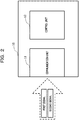
- FIG. 2 is a diagram illustrating a structure of a communication device 10.
- the communication device 10 includes a communication unit 11 and a control unit 12.
- the communication unit 11 receives a signal transmitted from the base station device 20.
- the communication unit 11 receives the first signal or the second signal.
- the control unit 12 controls the communication unit 11 to perform a signal process on the received signal. For example, when the first information is included in the subheader corresponding to the second signal, it is possible to recognize that the first signal and the second signal are simultaneously transmitted and control a data reception process such as a data composite process .
- the data reception process is, for example, a process of performing data composition for the second signal using information included in the second subheader and hybrid automatic repeat request (HARQ).
- HARQ hybrid automatic repeat request
- the base station device 20 may perform control so that the first information included in the subheader corresponding to the first signal is also transmitted by the subheader corresponding to the second signal, and cause the communication device 10 to recognize that the first signal and the second signal (or the information included in the second signal) are simultaneously transmitted. That is, since the base station device 20 performs control so that the first information included in the subheader corresponding to the first signal is also transmitted by the subheader corresponding to the second signal, the first signal and the second signal may be simultaneously transmitted, and it is possible to reduce the number of messages with the communication device 10. Accordingly, a time for the base station device 20 to transmit data to the communication device 10 is shortened, and a data transmission delay may be suppressed.
- the second embodiment may be understood as an example obtained by embodying the first embodiment.
- the base station device according to the first embodiment may be considered as being equivalent to a base station device 200 according to the present embodiment.
- the communication device according to the first embodiment may be considered as being equivalent to a terminal device 100 according to the present embodiment.
- FIG. 3 is a diagram illustrating a structure example of a communication system 30.
- the communication system 30 includes a terminal device 100 and a base station device 200.
- the communication system 30 is, for example, a communication system for wireless communication conforming to 5G.
- the base station device 200 is, for example, a gNodeB in 5G.
- the terminal device 100 is a device that performs communication with the base station device 200 or with another communication device through the base station device 200, and examples thereof include mobile communication terminals such as smartphones and tablet terminals.
- the base station device 200 may be referred to as a transmission source communication device that is a transmission source of data
- the terminal device 100 may be referred to as a transmission destination communication device that is a transmission destination of data.
- the base station device 200 and the terminal device 100 may establish wireless connection according to the random access procedure when data is transmitted from the base station device 200 to the terminal device 100, for example.
- a channel for the random access procedure is prepared.
- this channel is called a random access channel (RACH), and a communication start procedure using the RACH is called a random access procedure.
- RACH includes information called a preamble as information for the base station device to identify a radio signal transmitted by the terminal device 100. Based on this information, the base station device 200 identifies the terminal device 100.
- Examples of the random access procedure include a contention based random access procedure and a non-contention based random access procedure.
- the base station device 200 When an opportunity to transmit downlink data (DL data) occurs at the time in an uplink out of synchronous state, the base station device 200 usually performs the non-contention based random access procedure.
- control may be performed such that the contention based random access procedure is performed.
- FIG. 4 is a sequence illustrating an example of a contention based random access procedure.
- the base station device 200 transmits a shared preamble allocated to the terminal device 100 with a random access preamble assignment (message 0: Msg 0) (S11).
- the terminal device 100 receives the message 0
- the terminal device 100 transmits a random access preamble (message 1: Msg 1) to the base station device 200 through the RACH (S12).
- the base station device 200 receives the message 1
- the base station device 200 transmits a random access response (message 2: Msg 2) that is a response signal for the message 1 to the terminal device 100 together with a synchronous signal, transmission grant, and the like for uplink communication (S13).
- the terminal device 100 When the terminal device 100 receives the message 2, the terminal device 100 transmits a scheduled transmission (message 3: Msg 3) including an identifier or the like of a valid terminal device to the base station device 200 (S14). When the base station device 200 receives the message 3, the base station device 200 transmits a contention resolution (message 4: Msg 4) to the terminal device 100 (S15).
- a scheduled transmission (message 3: Msg 3) including an identifier or the like of a valid terminal device to the base station device 200 (S14).
- the base station device 200 When the base station device 200 receives the message 3, the base station device 200 transmits a contention resolution (message 4: Msg 4) to the terminal device 100 (S15).
- the base station device 200 transmits data (DL data) to the terminal device 100 using a radio resource established in the random access procedure (S16).
- the terminal device 100 transmits an acknowledgement (ACK) signal to the base station device 200 when the data is successfully received (S17), and transmits a non-acknowledgement (NACK) signal to the base station device 200 when the data is not received (S17).
- ACK acknowledgement
- NACK non-acknowledgement
- the access procedure includes a 2-step random access procedure (hereinafter, the 2-step random access procedure may be referred to as TSRA) that can reduce the number of times of message transmission and reception by a part or all of individual messages in the sequence being simultaneously transmitted.
- FIG. 5 is a diagram illustrating an example of a sequence of TSRA.
- the base station device 200 transmits the message 0 to the terminal device 100 (S21).
- the terminal device 100 transmits a message A (MsgA) including the message 1 and the message 3 to the base station device 200 (S22).
- the base station device 200 transmits a message B (MsgB) including the message 2 that is a response message of the message 1 and the message 4 that is a response message of the message 3 to the terminal device 100 (S23).
- the base station device 200 transmits the data (DL data) to the terminal device 100 using a radio resource established in the TSRA (S24).
- the terminal device 100 transmits an ACK signal to the base station device 200 when the data is successfully received (S25), and transmits a NACK signal to the base station device 200 when the data is not received (S25).
- the TSRA involves a smaller number of times of message transmission and reception than the contention based random access procedure illustrated in FIG. 4 , it is possible to suppress a data transmission delay by shorting the time of the random access procedure.
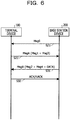
- FIG. 6 is a diagram illustrating an example of an alternative sequence of the TSRA. Processes S21 and S22 in the sequence in FIG. 6 are the same as the processes S21 and S22 illustrated in FIG. 5 .
- the base station device 200 When the based station 200 receives the message A, the base station device 200 simultaneously (or consecutively) transmits the message 2, the message 4, and furthermore data (second signal) to the terminal device 100 using the message B (first signal) (S31).
- the terminal device 100 transmits an ACK signal to the base station device 200 when the data is successfully received (S32), and transmits a NACK signal to the base station device 200 when the data is not received (S32).
- carrier sense may occur when each message is transmitted in the contention based random access procedure using an unlicensed-free band (the unlicensed band may be referred to as a non-licensed band or a dark licensed band).
- the carrier sense occurs, a delay until the completion of the transmission of data takes a longer time.
- a communication device such as the base station device 200 or the terminal device 100 is demanded to perform carrier sense, confirm that there is no signal (or no data) (equal to or less than a predetermined reception power) in the unlicensed band, and transmit the signal. Therefore, when the number of times of message transmission and reception increases, the number of times of carrier sense also increases. Thus, a delay until the completion of the transmission of data increases.
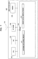
- FIG. 7 is a diagram illustrating a structure example of the base station device 200.
- the base station device 200 is, for example, a communication device, a transmission side communication device, and a transmission side device.
- the base station device 200 includes a central processing unit (CPU) 210, a storage 220, a memory 230 such as a dynamic random-access memory (DRAM), a network interface card (NIC) 240, and a radio frequency (RF) circuit 250.
- the base station device 200 is, for example, a transmission device that transmits data to the terminal device 100.
- the storage 220 is an auxiliary storage device, such as a flash memory, a hard disk drive (HDD), or a solid-state drive (SSD), for storing programs and data.
- the storage 220 stores a communication control program 221 and a random access control program 222.
- the memory 230 is an area into which programs stored in the storage 220 are loaded.
- the memory 230 is also used as an area in which a program stores data.
- the NIC 240 is a network interface connected to a network (not illustrated) such as Internet or an intranet.
- the base station device 200 communicates with a communication device coupled to the network through the NIC 240.
- the RF circuit 250 is a device wirelessly connected to the terminal device 100.
- the RF circuit 250 includes, for example, an antenna 251.
- the CPU 210 is a processor or a computer, which loads programs stored in the storage 220 into the memory 230 and executes the loaded programs to implement each process.
- the CPU 210 executes the communication control program 221 to implement the transmission unit and the control unit, and performs a communication control process.
- the communication control process is a process of controlling wireless communication with the terminal device 100.
- the CPU 210 implements the transmission unit and the control unit by executing the random access control program, and performs a random access control process.
- the random access control process is a process of controlling a random access procedure between the terminal devices 100.
- the base station device 200 selects, for example, a type (non-contention, contention, TSRA, transformed sequence of TSRA, or the like) of the random access procedure to be performed. Also, in the random access control process, the base station device 200 performs, for example, the selected random access procedure.
- the base station device 200 may select any one of the first format to the fifth format, which will be described below, or may use a format that is configure (determined) in advance.
- FIG. 8 illustrates a configuration example of the terminal device 100.
- Terminal device 100 is, for example, a second communication device, a reception side communication device, and a transmission party device.
- the terminal device 100 includes a CPU 110, a storage 120, a memory 130 such as a DRAM, and an RF circuit 150.
- the terminal device 100 is, for example, a reception device that receives data from the base station device 200.
- the storage 120 is an auxiliary storage device, such as a flash memory, an HDD, or a SSD, for storing programs and data.
- the storage 120 stores a communication program 121 and a random access program 122.
- the memory 130 is an area into which programs stored in the storage 120 are loaded.
- the memory 130 is also used as an area in which a program stores data.
- the RF circuit 150 is a device wirelessly connected to the base station device 200.
- the RF circuit 150 includes, for example, an antenna 151.
- the CPU 110 is a processor or a computer, which loads programs stored in the storage 120 into the memory 130 and executes the loaded programs to implement each process.
- the CPU 110 executes the communication program 121 to implement the reception unit and the reception control unit, and performs a communication process.
- the communication process is a process of performing wireless communication with the base station device 200.
- the CPU 110 implements the reception unit and the reception control unit by executing the random access program 122, and performs a random access process.
- the random access process is a process of performing a random access procedure selected by the base station device 200.
- the communication system 30 defines a format of a subheader of a random access response (RAR) (information to be transmitted with the first signal) including (or associating) a data portion.
- RAR random access response
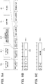
- FIG. 9A to 9C are diagrams illustrating an example of subheaders of a first format.
- FIG. 9A is a diagram illustrating an example of a sub protocol data unit (subPDU) of a medium access control (MAC) layer including the subheader.
- subPDU sub protocol data unit
- MAC medium access control
- the subPDU of the MAC layer may be referred to as a MAC subPDU.
- the downlink signal includes a plurality of MAC subPDUs (n MAC subPDUs) and padding.
- a subheader SH1 of a first MAC subPDU is an E/T/R/R/BI subheader indicating that a Backoff Indicator (BI) field is included.
- FIG. 9B is a diagram illustrating an example of the E/T/R/R/BI subheader.
- the E/T/R/R/BI subheader SH1 includes an extension (E) field, a type (T) field, 2-bit reseve (R) bits, and a BI field.
- the E field is an extension field. For example, when the E field is "1" (ON), it indicates that a following E/T/RAPID subheader or the like following that is associated. When the E field is "0" (OFF), it indicates that padding or RAR is followed.
- the T field is a type field. For example, when the T field is "0", it indicates that the BI field is included in the subheader. When the T field is "1", it indicates that the RAPID field is included in the subheader. In FIG. 9A , the T field is "0".
- the BI field is, for example, an indicator indicating a random standby time until the next random access is attempted when a reply may not be received in the random access.
- a subheader SH2 of a second MAC subPDU is an E/T/RAPID subheader indicating that a random access preamble identifier (RAPID) field is included.
- FIG. 9C is a diagram illustrating an example of the E/T/RAPID subheader.
- the E/T/RAPID subheader SH1 includes an E field, a T field, and a RAPID field.
- RAPID (first information) is an identifier of the random access preamble, and corresponds to the RAR to be transmitted. Also, in FIG. 9C , the T field is "1".
- a subheader SH3 of a third MAC subPDU is a subheader indicating that downlink data (DL data) is associated.
- the subheader SH3 indicating that downlink data is included in a payload following that is defined.
- the terminal device 100 may recognize that a payload P2 including the downlink data is associated after the payload P1 including the RAR, for example, and may acquire the downlink data.
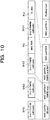
- FIG. 10 is a diagram illustrating an example of a second format.
- the second format indicates that the downlink data is associated by repeating the E/T/RAPID subheader.
- a subheader SH11 and a subheader SH12 are similar to the subheader SH1 and the subheader SH2 in FIG. 9 . Note that each of E fields of the subheader SH11 and the subheader SH12 is "1".
- An E field of the subheader SH3 of the third MAC subPDU is "1". Since the E field of the subheader SH3 is "1", the terminal device 100 recognizes that there is a subheader following that. The terminal device 100 acquires a subheader SH14 following a payload P11 including the RAR. When the terminal device 100 recognizes that the subheader SH14 is the repetition of the subheader SH13, the terminal device 100 may recognize that the subheader SH14 is followed by the payload P12 including the data. Accordingly, the terminal device 100 may acquire the downlink data.
- FIG. 11 is a diagram illustrating an example of a third format.
- the third format is an alternative example of the second format.
- "0" is set to the E field in the subheader (that is a border of the existing RAR) before the subPDU including data.
- a subheader SH21 is the same as the subheader SH11 in FIG. 10 . Unlike the subheader SH12 in FIG. 10 , the E field of a subheader SH22 is "0".
- a subheader SH23, a payload P21, a subheader SH24, and a payload P22 are similar to the subheader SH13, the payload P11, the subheader SH14, and the payload P12 in FIG. 10 .
- the terminal device 100 it is possible to simplify a decoding process by using the third format when the existing RAR and the RAR associating the data are multiplexed.
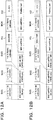
- FIG. 12A to 12B are diagrams illustrating an example of a range of the decoding process performed by the terminal device 100 that deal with the third format and the terminal device 100 that does not deal with the third format.
- FIG. 12A illustrates an example of the terminal device 100 that does not correspond to the third format
- FIG. 12B illustrates an example of the terminal device 100 that deal with the third format.
- the terminal device 100 When the terminal device 100 (the existing terminal device) acquires the subheader SH22, the terminal device 100 (the existing terminal device) that does not deal with the third format treats the following subheader SH23, payload P21, subheader SH24, and payload P22 as, for example, padding since the E field is "0", and the subheader SH23, the payload P21, the subheader SH24, and the payload P22 are not subjected to a decoding process. That is, a range (shaded portions) from the beginning (the subheader SH21) to the subheader (the subheader SH22) in which the E field is "0" is subjected to the decoding process performed by the terminal device 100 that does not deal with the third format.
- the terminal device 100 acquires the subheader SH22
- the terminal device 100 since the E field is "0", the terminal device 100 (a new terminal device) that deal with the third format recognizes that there may be RAR accompanying data thereafter. Then, the terminal device 100 acquires the subheader (the subheader SH23) of the RAR accompanying data, and the payload P21, the subheader SH24, and the payload P22 are subjected to the decoding process (shaded portions). Accordingly, the terminal device 100 may acquire the data.
- the additional decoding process in the terminal device that does not correspond to the third format may be omitted.
- the subheader following the subheader SH22 in which the E field is "0" may be a R/R/Logical Channel Identifier (LCID) subheader instead of the E/T/RAPID subheader.
- LCID R/R/Logical Channel Identifier
- FIG. 13 is a diagram illustrating an example in which a following subheader SH25 is the R/R/LCID subheader.
- the terminal device 100 receives the subheader SH22 in which the E field is "0"
- the terminal device 100 determines whether the subheader following that is the E/T/RAPID subheader or the R/R/LCID subheader.
- the terminal device 100 performs a subheader type determination process S100.
- FIG. 14 is a diagram illustrating an example of a process flowchart of the subheader type determination process S100.
- the terminal device 100 awaits a subheader that appears following the subheader in which the E field is "0" (No at S100-1). Then, when the terminal device 100 acquires the subheader that appears following the subheader in which the E field is "0" (Yes at S100-1), the terminal device 100 confirms whether or not the second bit of the acquired subheader is ON (1) (S100-2).
- the terminal device 100 determines that a subheader is the E/T/RAPID subheader (S100-3).
- the terminal device 100 determines that a subheader is the R/R/LCID subheader (S100-4).
- the terminal device 100 determines that the subheader SH25 is the R/R/LCID subheader.
- the terminal device 100 may classify whether the subheader is the E/T/RAPID subheader or the R/R/LCID subheader.
- the E/T/R/R/BI subheader may not be set following the subheader in which the E field is "0". Therefore, the T field may be redefined.
- FIG. 15A to 15B are diagrams illustrating examples of formats of redefined subheaders.
- FIG. 15A illustrates an example of a subheader including the LCID
- FIG. 15B illustrates an example of a subheader including the RAPID.
- the last six bits are defined as the LCID.
- the T field is "1" in the subheader following the subheader in which the E field is "0”
- the last six bits are defined as the RAPID.
- the terminal device 100 may determine whether the subheader is the E/T/LCID subheader or the E/T/RAPID subheader by confirming the second bit.
- FIG. 16 is a diagram illustrating an example without padding. As illustrated in FIG. 16 , when there is no data following the subheader SH22, the "0" of the E field included in the subheader SH22 is determined that there is no following data (that is, the tail), by the terminal device 100.
- FIG. 17 is a diagram illustrating an example of a fourth format.
- a subheader SH31, a subheader SH32, a subheader SH33, and a payload P32 in FIG. 17 are similar to the subheader SH11, the subheader SH12, the subheader SH13, and the payload P12 in FIG. 10 .
- one of the R bits in the payload P31 including the RAR is used as a bit indicating whether or not the data following that is included. For example, when the defined R bit in the payload P31 is ON (1), this indicates that there is data following the RAR. As illustrated in FIG. 17 , the terminal device 100 confirms that the defined R bit of the payload P31 including the RAR is "1", and recognizes that there is the payload P32 including the data following that.
- FIG. 18 is a diagram illustrating an example of a fifth format.
- the fifth format allows "0" to be set in the T field of the E/T/RAPID subheader that appears in the middle (that appears at a position other than the beginning).
- the T field in the subheader appearing in the middle is "0"
- the case indicates that the data is associated.
- a subheader SH41 and a subheader SH42 are similar to the subheader SH1 and the subheader SH2 in FIG. 9 . Also, a payload P41 and a payload P42 are similar to the payload P1 and the payload P2 in FIG. 9 .
- a T field of an E/T/RAPID subheader SH43 is "0". Since the terminal devices has already received that T field is "0" at the subheader SH41, the terminal device 100 recognizes that "0" of the T field in the subheader SH43 is the second reception ("0" of the T field appears in the middle), and recognizes that data is associated following that. In other words, the terminal device 100 recognizes a format different from the existing format by permitting "0" of the T field for the E/T/RAPID subheader located in the middle. The terminal device 100 acquires data included in the payload P42 following the payload P41 including the RAR.
- FIG. 19 is a diagram illustrating an example of parameters of backoff parameter values.
- the indices and backoff parameter values set in the BI field are defined in TS38.321 Subclause 7.2.
- "0" of the backoff parameter value (standby time) is newly defined in an index 14 that has been defined as Reseved.
- the above described data may be, for example, user date or MAC Control Element (CE).
- CE MAC Control Element
- the format of MAC CE is described in, for example, TS38.321 FIG. 6.1.2-4.
- the base station device 200 may simultaneously transmit, for example, Cell Group (CG) activation MAC CE with the message B. Accordingly, the time until the transmission of the MAC CE message is completed may be shortened, and the data transmission delay may be suppressed.
- CG Cell Group
- the embodiments may be combined with each other.
- the terminal device 100 and the base station device 200 may correspond to any one of the first format to the fifth format, or may correspond to a combination of two or more of formats.
- the terminal device 100 and the base station device 200 may use different message formats, for example, according to a radio wave state (the degree of interference, the received power, or the like).
Landscapes
- Engineering & Computer Science (AREA)
- Computer Networks & Wireless Communication (AREA)
- Signal Processing (AREA)
- Mobile Radio Communication Systems (AREA)
Abstract
Description
- The embodiments discussed herein are related to a communication device, a second communication device, a communication system, and a communication method.
- In a current communication network, the traffic of mobile terminals (smartphones and feature phones) accounts for a majority of communication network resources. Furthermore, the traffic used by mobile terminals tend to expand.
- Meanwhile, in the communication network, with the development of evolution of Internet of Things (IoT) services (e.g., monitoring systems such as a traffic system, a smart meter, and a device), it has been demanded to cope with services including various requirement. Consequently, in the communication standards for the 5th generation mobile communication (5G or new radio (NR)), it has been demanded that, in addition to standard techniques of the 4th generation mobile communication (4G) (for example, see
NPLs 1 to 12), techniques, which achieve a higher data rate, a larger capacity, and lower latency. Note that, in the 5th generation communication standards, 3GPP working groups (such as, e.g., TSG-RAN WG1 and TSG-RAN WG2)) have been making a progress on technical study and the first version was released in December 2017 (seeNPLs 13 to 40). - In order to support various kinds of services as described above, the 5G is assumed to support many use cases categorized, e.g., enhanced mobile broadband (eMBB), massive machine type communications (MTC), and ultra-reliable and low latency communication (URLLC).
- In a wireless communication system, a channel for first transmission by a communication device (for example, a terminal device) at the start of communication between a base station device and the communication device is prepared. In the 3GPP, this channel is called a random access channel (RACH), and a communication start procedure using the RACH is called a random access procedure. The RACH includes information called a preamble as information for a base station to identify a radio signal transmitted by the communication device. This information enables the base station device to identify the terminal device.
- Note that the random access procedure is performed in a case of executing an initial access, a case where a data signal is generated, a case of establishing a synchronous state during handover, or other cases.
- In the wireless communication system, the random access procedure is performed to establish a synchronous state (uplink synchronous state), and data communication is then performed.
- The technologies related to the 5G are described in the following citation list.
-
- NPL 1: 3GPP TS 36.133 V15.5.0 (2018-12)
- NPL 2: 3GPP TS 36.211 V15.4.0 (2018-12)
- NPL 3: 3GPP TS 36.212 V15.4.0 (2018-12)
- NPL 4: 3GPP TS 36.213 V15.4.0 (2018-12)
- NPL 5: 3GPP TS 36.300 V15.4.0 (2018-12)
- NPL 6: 3GPP TS 36.321 V15.4.0 (2018-12)
- NPL 7: 3GPP TS 36.322 V15.1.0 (2018-07)
- NPL 8: 3GPP TS 36.323 V15.2.0 (2018-12)
- NPL 9: 3GPP TS 36.331 V15.4.0 (2018-12)
- NPL 10: 3GPP TS 36.413 V15.4.0 (2018-12)
- NPL 11: 3GPP TS 36.423 V15.4.0 (2018-06)
- NPL 12: 3GPP TS 36.425 V15.0.0 (2018-06)
- NPL 13: 3GPP TS 37.340 V15.4.0 (2018-12)
- NPL 14: 3GPP TS 38.201 V15.0.0 (2017-12)
- NPL 15: 3GPP TS 38.202 V15.4.0 (2018-12)
- NPL 16: 3GPP TS 38.211 V15.4.0 (2018-12)
- NPL 17: 3GPP TS 38.212 V15.4.0 (2018-12)
- NPL 18: 3GPP TS 38.213 V15.4.0 (2018-12)
- NPL 19: 3GPP TS 38.214 V15.4.0 (2018-12)
- NPL 20: 3GPP TS 38.215 V15.4.0 (2018-12)
- NPL 21: 3GPP TS 38.300 V15.4.0 (2018-12)
- NPL 22: 3GPP TS 38.321 V15.4.0 (2018-12)
- NPL 23: 3GPP TS 38.322 V15.4.0 (2018-12)
- NPL 24: 3GPP TS 38.323 V15.4.0 (2018-12)
- NPL 25: 3GPP TS 38.331 V15.4.0 (2018-12)
- NPL 26: 3GPP TS 38.401 V15.4.0 (2018-12)
- NPL 27: 3GPP TS 38.410 V15.2.0 (2018-12)
- NPL 28: 3GPP TS 38.413 V15.2.0 (2018-12)
- NPL 29: 3GPP TS 38.420 V15.2.0 (2018-12)
- NPL 30: 3GPP TS 38.423 V15.2.0 (2018-12)
- NPL 31: 3GPP TS 38.470 V15.4.0 (2018-12)
- NPL 32: 3GPP TS 38.473 V15.4.1 (2019-01)
- NPL 33: 3GPP TR 38.801 V14.0.0 (2017-03)
- NPL 34: 3GPP TR 38.802 V14.2.0 (2017-09)
- NPL 35: 3GPP TR 38.803 V14.2.0 (2017-09)
- NPL 36: 3GPP TR 38.804 V14.0.0 (2017-03)
- NPL 37: 3GPP TR 38.900 V15.0.0 (2018-06)
- NPL 38: 3GPP TR 38.912 V15.0.0 (2018-06)
- NPL 39: 3GPP TR 38.913 V15.0.0 (2018-06)
- NPL 40: 3GPP TR 38.889 V15.0.0 (2018-12)
- There is a demand to reduce a delay time of data signal communication in the wireless communication system. For example, there is a case where the delay time when the wireless communication system is able to support URLLC services assumed in the 5G is demanded. Therefore, for example, reducing the delay time until data signal transmission is demanded even when a data signal is generated in a situation where the communication device and the base station device are out of synchronization.
- The disclosed technology is to provide a communication device, a second communication device, a communication system, and a communication method that reduces a delay time until data signal transmission.
- According to an aspect of the embodiments, a communication device that performs a random access procedure includes a transmission unit that is able to transmit a first signal in the random access procedure and a second signal that is not a signal of the random access procedure, and a control unit that is able to perform control so that first information included in a first subheader corresponding to the first signal is included in a second subheader corresponding to the second signal and is transmitted.
- In one disclosure, it is possible to reduce the delay amount until the data signal transmission.
-
- [
FIG. 1] FIG. 1 illustrates a structure example of abase station device 20. - [
FIG. 2] FIG. 2 illustrates a structure example of acommunication device 10. - [
FIG. 3] FIG. 3 illustrates a structure example of acommunication system 30. - [
FIG. 4] FIG. 4 is a sequence illustrating an example of a contention based random access procedure. - [
FIG. 5] FIG. 5 is a diagram illustrating an example of a sequence of TSRA. - [
FIG. 6] FIG. 6 is a diagram illustrating an example of a transformed sequence of TSRA. - [
FIG. 7] FIG. 7 is a diagram illustrating a structure example of abase station device 200. - [
FIG. 8] FIG. 8 is a diagram illustrating a structure example of aterminal device 100. - [
FIG. 9] FIG. 9A to 9C are a diagram illustrating an example of subheaders of a first format. - [
FIG. 10] FIG. 10 is a diagram illustrating an example of a second format. - [
FIG. 11] FIG. 11 is a diagram illustrating an example of a third format. - [
FIG. 12] FIG. 12A to 12B are a diagram illustrating an example of a range of a decoding process performed by theterminal device 100 that deals with the third format and theterminal device 100 that does not deal with the third format. - [
FIG. 13] FIG. 13 is a diagram illustrating an example in which a subheader SH25 following that is a R/R/LCID subheader. - [
FIG. 14] FIG. 14 is a diagram illustrating an example of a process flowchart of a subheader type determination process S100. - [
FIG. 15] FIG. 15A to 15B are a diagram illustrating examples of formats of redefined subheaders. - [
FIG. 16] FIG. 16 is a diagram illustrating an example without padding. - [
FIG. 17] FIG. 17 is a diagram illustrating an example of a fourth format. - [
FIG. 18] FIG. 18 is a diagram illustrating an example of a fifth format. - [
FIG. 19] FIG. 19 is a diagram illustrating an example of parameters of backoff parameter values. - Hereinafter, the present embodiments will be described in detail with reference to the drawings. The problems and the embodiments in the present specification are merely examples, and do not limit the scope of the present application. In particular, as long as the described expressions are technically comparable even if different described expressions are used, the techniques of the present application may be applied to the different described expressions, and the scope of rights is not limited thereby..
- A first embodiment is described below.
-
FIG. 1 is a diagram illustrating a structure example of abase station device 20. Thebase station device 20 is, for example, a communication device and a transmission source communication device. Thebase station device 20 transmits a first signal and a second signal to a transmission destination communication device (not illustrated). Also, thebase station device 20 is a communication device that transmits data. - The
base station device 20 includes atransmission unit 21 and acontrol unit 22. Thetransmission unit 21 and thecontrol unit 22 are implemented by, for example, a computer or a processor loading and executing a program, which is included in thebase station device 20. - The
base station device 20 performs a random access procedure when transmitting data to the transmission destination communication device. The random access procedure is a procedure for establishing wireless connection in wireless communication performed between thebase station device 20 and the transmission destination communication device, and is performed when a data signal to be transmitted is generated or a case of establishing a synchronous state during handover. - The first signal is a signal that is used in the random access procedure by the
base station device 20. The subheader corresponding to the first signal includes first information corresponding to information transmitted with the first signal. The first information is information that is used for establishing wireless connection in the random access procedure. - The second signal is a signal that is not used for the random access procedure, and is, for example, a signal for transmitting data.
- The
transmission unit 21 transmits the first signal and the second signal. Thetransmission unit 21 may transmit the first signal and the second signal at different timings or may simultaneously (consecutively) transmit the first signal and the second signal. - The
control unit 22 may perform control so that the first information included in the subheader corresponding to the first signal is also transmitted to the subheader corresponding to the second signal. When thetransmission unit 21 transmits the second signal at the same time as the transmission of the first signal, thecontrol unit 22 causes the transmission destination communication device to recognize that the second signal (or information included in the second signal) is transmitted at the same time as the transmission of the first signal by transmitting the first information included in the subheader corresponding to the second signal (or repeatedly transmitting the subheader including the first information). -
FIG. 2 is a diagram illustrating a structure of acommunication device 10. Thecommunication device 10 includes acommunication unit 11 and acontrol unit 12. - The
communication unit 11 receives a signal transmitted from thebase station device 20. For example, thecommunication unit 11 receives the first signal or the second signal. - The
control unit 12 controls thecommunication unit 11 to perform a signal process on the received signal. For example, when the first information is included in the subheader corresponding to the second signal, it is possible to recognize that the first signal and the second signal are simultaneously transmitted and control a data reception process such as a data composite process . - Note that, the data reception process is, for example, a process of performing data composition for the second signal using information included in the second subheader and hybrid automatic repeat request (HARQ).
- In the first embodiment, the
base station device 20 may perform control so that the first information included in the subheader corresponding to the first signal is also transmitted by the subheader corresponding to the second signal, and cause thecommunication device 10 to recognize that the first signal and the second signal (or the information included in the second signal) are simultaneously transmitted. That is, since thebase station device 20 performs control so that the first information included in the subheader corresponding to the first signal is also transmitted by the subheader corresponding to the second signal, the first signal and the second signal may be simultaneously transmitted, and it is possible to reduce the number of messages with thecommunication device 10. Accordingly, a time for thebase station device 20 to transmit data to thecommunication device 10 is shortened, and a data transmission delay may be suppressed. - Next, a second embodiment is described below. The second embodiment may be understood as an example obtained by embodying the first embodiment. For example, the base station device according to the first embodiment may be considered as being equivalent to a
base station device 200 according to the present embodiment. Also, for example, the communication device according to the first embodiment may be considered as being equivalent to aterminal device 100 according to the present embodiment. -
FIG. 3 is a diagram illustrating a structure example of acommunication system 30. Thecommunication system 30 includes aterminal device 100 and abase station device 200. Thecommunication system 30 is, for example, a communication system for wireless communication conforming to 5G. In this case, thebase station device 200 is, for example, a gNodeB in 5G. Also, theterminal device 100 is a device that performs communication with thebase station device 200 or with another communication device through thebase station device 200, and examples thereof include mobile communication terminals such as smartphones and tablet terminals. Note that, in the following description, thebase station device 200 may be referred to as a transmission source communication device that is a transmission source of data, and theterminal device 100 may be referred to as a transmission destination communication device that is a transmission destination of data. - In the
communication system 30, thebase station device 200 and theterminal device 100 may establish wireless connection according to the random access procedure when data is transmitted from thebase station device 200 to theterminal device 100, for example. - In the
communication system 30, a channel for the random access procedure is prepared. In 3GPP, this channel is called a random access channel (RACH), and a communication start procedure using the RACH is called a random access procedure. The RACH includes information called a preamble as information for the base station device to identify a radio signal transmitted by theterminal device 100. Based on this information, thebase station device 200 identifies theterminal device 100. - Examples of the random access procedure include a contention based random access procedure and a non-contention based random access procedure. When an opportunity to transmit downlink data (DL data) occurs at the time in an uplink out of synchronous state, the
base station device 200 usually performs the non-contention based random access procedure. However, for example, when it is difficult to allocate a dedicated preamble due to a shortage of a dedicated preamble specific to a terminal or the like, control may be performed such that the contention based random access procedure is performed. -
FIG. 4 is a sequence illustrating an example of a contention based random access procedure. Thebase station device 200 transmits a shared preamble allocated to theterminal device 100 with a random access preamble assignment (message 0: Msg 0) (S11). When theterminal device 100 receives themessage 0 , theterminal device 100 transmits a random access preamble (message 1: Msg 1) to thebase station device 200 through the RACH (S12). When thebase station device 200 receives themessage 1, thebase station device 200 transmits a random access response (message 2: Msg 2) that is a response signal for themessage 1 to theterminal device 100 together with a synchronous signal, transmission grant, and the like for uplink communication (S13). - When the
terminal device 100 receives themessage 2, theterminal device 100 transmits a scheduled transmission (message 3: Msg 3) including an identifier or the like of a valid terminal device to the base station device 200 (S14). When thebase station device 200 receives themessage 3, thebase station device 200 transmits a contention resolution (message 4: Msg 4) to the terminal device 100 (S15). - The
base station device 200 transmits data (DL data) to theterminal device 100 using a radio resource established in the random access procedure (S16). Theterminal device 100 transmits an acknowledgement (ACK) signal to thebase station device 200 when the data is successfully received (S17), and transmits a non-acknowledgement (NACK) signal to thebase station device 200 when the data is not received (S17). - Also, the access procedure includes a 2-step random access procedure (hereinafter, the 2-step random access procedure may be referred to as TSRA) that can reduce the number of times of message transmission and reception by a part or all of individual messages in the sequence being simultaneously transmitted.
FIG. 5 is a diagram illustrating an example of a sequence of TSRA. - The
base station device 200 transmits themessage 0 to the terminal device 100 (S21). When theterminal device 100 receives themessage 0, theterminal device 100 transmits a message A (MsgA) including themessage 1 and themessage 3 to the base station device 200 (S22). When thebase station device 200 receives the message A, thebase station device 200 transmits a message B (MsgB) including themessage 2 that is a response message of themessage 1 and the message 4 that is a response message of themessage 3 to the terminal device 100 (S23). - The
base station device 200 transmits the data (DL data) to theterminal device 100 using a radio resource established in the TSRA (S24). Theterminal device 100 transmits an ACK signal to thebase station device 200 when the data is successfully received (S25), and transmits a NACK signal to thebase station device 200 when the data is not received (S25). - As illustrated in
FIG. 5 , since the TSRA involves a smaller number of times of message transmission and reception than the contention based random access procedure illustrated inFIG. 4 , it is possible to suppress a data transmission delay by shorting the time of the random access procedure. - In addition, furthermore, in order to reduce the number of times of message transmission and reception, there is a transformed sequence of the TSRA in which downlink data in the TSRA is included in the message B and transmitted.
FIG. 6 is a diagram illustrating an example of an alternative sequence of the TSRA. Processes S21 and S22 in the sequence inFIG. 6 are the same as the processes S21 and S22 illustrated inFIG. 5 . - When the based
station 200 receives the message A, thebase station device 200 simultaneously (or consecutively) transmits themessage 2, the message 4, and furthermore data (second signal) to theterminal device 100 using the message B (first signal) (S31). Theterminal device 100 transmits an ACK signal to thebase station device 200 when the data is successfully received (S32), and transmits a NACK signal to thebase station device 200 when the data is not received (S32). - In the alternative sequence of the TSRA, since only one message may be omitted as compared with the sequence of the TSRA illustrated in
FIG. 6 , it is possible to further shorten the time of the random access procedure and further suppress the data transmission delay. - In the random access procedure, carrier sense may occur when each message is transmitted in the contention based random access procedure using an unlicensed-free band (the unlicensed band may be referred to as a non-licensed band or a dark licensed band). When the carrier sense occurs, a delay until the completion of the transmission of data takes a longer time.
- When a signal (a message or data) is transmitted using the unlicensed band, a communication device such as the
base station device 200 or theterminal device 100 is demanded to perform carrier sense, confirm that there is no signal (or no data) (equal to or less than a predetermined reception power) in the unlicensed band, and transmit the signal. Therefore, when the number of times of message transmission and reception increases, the number of times of carrier sense also increases. Thus, a delay until the completion of the transmission of data increases. - Therefore, in the alternative sequence of the TSRA, When the unlicensed band is used, the number of times of carrier sense is reduced in addition to the reduction of the transmission and reception of messages in comparison with the other methods (
FIGs. 4 and5 ). Thus, it is possible to further suppress the data transmission delay. -
FIG. 7 is a diagram illustrating a structure example of thebase station device 200. Thebase station device 200 is, for example, a communication device, a transmission side communication device, and a transmission side device. Thebase station device 200 includes a central processing unit (CPU) 210, astorage 220, amemory 230 such as a dynamic random-access memory (DRAM), a network interface card (NIC) 240, and a radio frequency (RF)circuit 250. Thebase station device 200 is, for example, a transmission device that transmits data to theterminal device 100. - The
storage 220 is an auxiliary storage device, such as a flash memory, a hard disk drive (HDD), or a solid-state drive (SSD), for storing programs and data. Thestorage 220 stores acommunication control program 221 and a randomaccess control program 222. - The
memory 230 is an area into which programs stored in thestorage 220 are loaded. Thememory 230 is also used as an area in which a program stores data. - The
NIC 240 is a network interface connected to a network (not illustrated) such as Internet or an intranet. Thebase station device 200 communicates with a communication device coupled to the network through theNIC 240. - The
RF circuit 250 is a device wirelessly connected to theterminal device 100. TheRF circuit 250 includes, for example, anantenna 251. - The
CPU 210 is a processor or a computer, which loads programs stored in thestorage 220 into thememory 230 and executes the loaded programs to implement each process. - The
CPU 210 executes thecommunication control program 221 to implement the transmission unit and the control unit, and performs a communication control process. The communication control process is a process of controlling wireless communication with theterminal device 100. - The
CPU 210 implements the transmission unit and the control unit by executing the random access control program, and performs a random access control process. The random access control process is a process of controlling a random access procedure between theterminal devices 100. In the random access control process, thebase station device 200 selects, for example, a type (non-contention, contention, TSRA, transformed sequence of TSRA, or the like) of the random access procedure to be performed. Also, in the random access control process, thebase station device 200 performs, for example, the selected random access procedure. - Note that, when the alternative sequence of the TSRA is selected in the random access control process, for example, the
base station device 200 may select any one of the first format to the fifth format, which will be described below, or may use a format that is configure (determined) in advance. -
FIG. 8 illustrates a configuration example of theterminal device 100.Terminal device 100 is, for example, a second communication device, a reception side communication device, and a transmission party device. Theterminal device 100 includes aCPU 110, astorage 120, amemory 130 such as a DRAM, and anRF circuit 150. Theterminal device 100 is, for example, a reception device that receives data from thebase station device 200. - The
storage 120 is an auxiliary storage device, such as a flash memory, an HDD, or a SSD, for storing programs and data. Thestorage 120 stores acommunication program 121 and arandom access program 122. - The
memory 130 is an area into which programs stored in thestorage 120 are loaded. Thememory 130 is also used as an area in which a program stores data. - The
RF circuit 150 is a device wirelessly connected to thebase station device 200. TheRF circuit 150 includes, for example, anantenna 151. - The
CPU 110 is a processor or a computer, which loads programs stored in thestorage 120 into thememory 130 and executes the loaded programs to implement each process. - The
CPU 110 executes thecommunication program 121 to implement the reception unit and the reception control unit, and performs a communication process. The communication process is a process of performing wireless communication with thebase station device 200. - The
CPU 110 implements the reception unit and the reception control unit by executing therandom access program 122, and performs a random access process. The random access process is a process of performing a random access procedure selected by thebase station device 200. - In the alternative sequence of the TSRA, the
communication system 30 defines a format of a subheader of a random access response (RAR) (information to be transmitted with the first signal) including (or associating) a data portion. A message format in the transformed sequence of the TSRA will be described below. -
FIG. 9A to 9C are diagrams illustrating an example of subheaders of a first format.FIG. 9A is a diagram illustrating an example of a sub protocol data unit (subPDU) of a medium access control (MAC) layer including the subheader. Hereinafter, the subPDU of the MAC layer may be referred to as a MAC subPDU. - In
FIG. 9A , the downlink signal includes a plurality of MAC subPDUs (n MAC subPDUs) and padding. For example, a subheader SH1 of a first MAC subPDU is an E/T/R/R/BI subheader indicating that a Backoff Indicator (BI) field is included.FIG. 9B is a diagram illustrating an example of the E/T/R/R/BI subheader. The E/T/R/R/BI subheader SH1 includes an extension (E) field, a type (T) field, 2-bit reseve (R) bits, and a BI field. - The E field is an extension field. For example, when the E field is "1" (ON), it indicates that a following E/T/RAPID subheader or the like following that is associated. When the E field is "0" (OFF), it indicates that padding or RAR is followed.
- The T field is a type field. For example, when the T field is "0", it indicates that the BI field is included in the subheader. When the T field is "1", it indicates that the RAPID field is included in the subheader. In
FIG. 9A , the T field is "0". - The BI field is, for example, an indicator indicating a random standby time until the next random access is attempted when a reply may not be received in the random access.
- A subheader SH2 of a second MAC subPDU is an E/T/RAPID subheader indicating that a random access preamble identifier (RAPID) field is included.
FIG. 9C is a diagram illustrating an example of the E/T/RAPID subheader. The E/T/RAPID subheader SH1 includes an E field, a T field, and a RAPID field. RAPID (first information) is an identifier of the random access preamble, and corresponds to the RAR to be transmitted. Also, inFIG. 9C , the T field is "1". - A subheader SH3 of a third MAC subPDU is a subheader indicating that downlink data (DL data) is associated. In the
communication system 30, the subheader SH3 indicating that downlink data is included in a payload following that is defined. - By receiving the subheader SH3, the
terminal device 100 may recognize that a payload P2 including the downlink data is associated after the payload P1 including the RAR, for example, and may acquire the downlink data. -
FIG. 10 is a diagram illustrating an example of a second format. The second format indicates that the downlink data is associated by repeating the E/T/RAPID subheader. - A subheader SH11 and a subheader SH12 are similar to the subheader SH1 and the subheader SH2 in
FIG. 9 . Note that each of E fields of the subheader SH11 and the subheader SH12 is "1". - An E field of the subheader SH3 of the third MAC subPDU is "1". Since the E field of the subheader SH3 is "1", the
terminal device 100 recognizes that there is a subheader following that. Theterminal device 100 acquires a subheader SH14 following a payload P11 including the RAR. When theterminal device 100 recognizes that the subheader SH14 is the repetition of the subheader SH13, theterminal device 100 may recognize that the subheader SH14 is followed by the payload P12 including the data. Accordingly, theterminal device 100 may acquire the downlink data. -
FIG. 11 is a diagram illustrating an example of a third format. The third format is an alternative example of the second format. In the third format, "0" is set to the E field in the subheader (that is a border of the existing RAR) before the subPDU including data. - A subheader SH21 is the same as the subheader SH11 in
FIG. 10 . Unlike the subheader SH12 inFIG. 10 , the E field of a subheader SH22 is "0". Hereinafter, a subheader SH23, a payload P21, a subheader SH24, and a payload P22 are similar to the subheader SH13, the payload P11, the subheader SH14, and the payload P12 inFIG. 10 . - In the
terminal device 100, it is possible to simplify a decoding process by using the third format when the existing RAR and the RAR associating the data are multiplexed. -
FIG. 12A to 12B are diagrams illustrating an example of a range of the decoding process performed by theterminal device 100 that deal with the third format and theterminal device 100 that does not deal with the third format.FIG. 12A illustrates an example of theterminal device 100 that does not correspond to the third format, andFIG. 12B illustrates an example of theterminal device 100 that deal with the third format. - When the terminal device 100 (the existing terminal device) acquires the subheader SH22, the terminal device 100 (the existing terminal device) that does not deal with the third format treats the following subheader SH23, payload P21, subheader SH24, and payload P22 as, for example, padding since the E field is "0", and the subheader SH23, the payload P21, the subheader SH24, and the payload P22 are not subjected to a decoding process. That is, a range (shaded portions) from the beginning (the subheader SH21) to the subheader (the subheader SH22) in which the E field is "0" is subjected to the decoding process performed by the
terminal device 100 that does not deal with the third format. - On the other hand, when the terminal device 100 (a new terminal device) acquires the subheader SH22, since the E field is "0", the terminal device 100 (a new terminal device) that deal with the third format recognizes that there may be RAR accompanying data thereafter. Then, the
terminal device 100 acquires the subheader (the subheader SH23) of the RAR accompanying data, and the payload P21, the subheader SH24, and the payload P22 are subjected to the decoding process (shaded portions). Accordingly, theterminal device 100 may acquire the data. - As described above, by using the third format, the additional decoding process in the terminal device that does not correspond to the third format may be omitted.
- Note that, in the third format, the subheader following the subheader SH22 in which the E field is "0" may be a R/R/Logical Channel Identifier (LCID) subheader instead of the E/T/RAPID subheader.
-
FIG. 13 is a diagram illustrating an example in which a following subheader SH25 is the R/R/LCID subheader. In the third format, when theterminal device 100 receives the subheader SH22 in which the E field is "0", theterminal device 100 determines whether the subheader following that is the E/T/RAPID subheader or the R/R/LCID subheader. Theterminal device 100 performs a subheader type determination process S100. -
FIG. 14 is a diagram illustrating an example of a process flowchart of the subheader type determination process S100. Theterminal device 100 awaits a subheader that appears following the subheader in which the E field is "0" (No at S100-1). Then, when theterminal device 100 acquires the subheader that appears following the subheader in which the E field is "0" (Yes at S100-1), theterminal device 100 confirms whether or not the second bit of the acquired subheader is ON (1) (S100-2). - When the second bit is ON (Yes at S100-2), the
terminal device 100 determines that a subheader is the E/T/RAPID subheader (S100-3). - On the other hand, when the second bit is not ON (No at S100-2), the
terminal device 100 determines that a subheader is the R/R/LCID subheader (S100-4). - Referring back to
FIG. 13 , since the second bit of the subheader SH25 is "0" and is not ON, theterminal device 100 determines that the subheader SH25 is the R/R/LCID subheader. - In this manner, in the third format, by confirming the second bit of the subheader, the
terminal device 100 may classify whether the subheader is the E/T/RAPID subheader or the R/R/LCID subheader. - Note that the E/T/R/R/BI subheader may not be set following the subheader in which the E field is "0". Therefore, the T field may be redefined.
-
FIG. 15A to 15B are diagrams illustrating examples of formats of redefined subheaders.FIG. 15A illustrates an example of a subheader including the LCID, andFIG. 15B illustrates an example of a subheader including the RAPID. - As illustrated in
FIG. 15A , when the T field is "0" in the subheader following the subheader in which the E field is "0", the last six bits are defined as the LCID. Also, as illustrated inFIG. 15B , when the T field is "1" in the subheader following the subheader in which the E field is "0", the last six bits are defined as the RAPID. - Note that, even when the T field is redefined as illustrated in
FIG. 15 , theterminal device 100 may determine whether the subheader is the E/T/LCID subheader or the E/T/RAPID subheader by confirming the second bit. - Also, when padding is not demanded to follow, the
terminal device 100 interprets "0" of the E field included in the subheader SH22 as the tail.FIG. 16 is a diagram illustrating an example without padding. As illustrated inFIG. 16 , when there is no data following the subheader SH22, the "0" of the E field included in the subheader SH22 is determined that there is no following data (that is, the tail), by theterminal device 100. -
FIG. 17 is a diagram illustrating an example of a fourth format. A subheader SH31, a subheader SH32, a subheader SH33, and a payload P32 inFIG. 17 are similar to the subheader SH11, the subheader SH12, the subheader SH13, and the payload P12 inFIG. 10 . - In the fourth format, it is defined that one of the R bits in the payload P31 including the RAR is used as a bit indicating whether or not the data following that is included. For example, when the defined R bit in the payload P31 is ON (1), this indicates that there is data following the RAR. As illustrated in
FIG. 17 , theterminal device 100 confirms that the defined R bit of the payload P31 including the RAR is "1", and recognizes that there is the payload P32 including the data following that. -
FIG. 18 is a diagram illustrating an example of a fifth format. The fifth format allows "0" to be set in the T field of the E/T/RAPID subheader that appears in the middle (that appears at a position other than the beginning). When the T field in the subheader appearing in the middle is "0", the case indicates that the data is associated. - A subheader SH41 and a subheader SH42 are similar to the subheader SH1 and the subheader SH2 in
FIG. 9 . Also, a payload P41 and a payload P42 are similar to the payload P1 and the payload P2 inFIG. 9 . - A T field of an E/T/RAPID subheader SH43 is "0". Since the terminal devices has already received that T field is "0" at the subheader SH41, the
terminal device 100 recognizes that "0" of the T field in the subheader SH43 is the second reception ("0" of the T field appears in the middle), and recognizes that data is associated following that. In other words, theterminal device 100 recognizes a format different from the existing format by permitting "0" of the T field for the E/T/RAPID subheader located in the middle. Theterminal device 100 acquires data included in the payload P42 following the payload P41 including the RAR. - Note that, in order to allow "0" for the T field of the E/T/RAPID subheader, there is a condition in which the E/T/R/R/BI subheader appears at the beginning. However, since a numerical value specified in the BI field is an index corresponding to a random standby time (backoff parameter value) until the next random access is attempted when there is no response to the random access, a subheader including the BI field may not be set (transmitted) when the standby time is 0. Therefore, 0 of the standby time is defined as one index.
-
FIG. 19 is a diagram illustrating an example of parameters of backoff parameter values. For example, the indices and backoff parameter values set in the BI field are defined in TS38.321 Subclause 7.2. InFIG. 19 , "0" of the backoff parameter value (standby time) is newly defined in anindex 14 that has been defined as Reseved. - The above described data may be, for example, user date or MAC Control Element (CE). The format of MAC CE is described in, for example, TS38.321 FIG. 6.1.2-4. The
base station device 200 may simultaneously transmit, for example, Cell Group (CG) activation MAC CE with the message B. Accordingly, the time until the transmission of the MAC CE message is completed may be shortened, and the data transmission delay may be suppressed. - Also, the embodiments may be combined with each other. In the
communication system 30, theterminal device 100 and thebase station device 200 may correspond to any one of the first format to the fifth format, or may correspond to a combination of two or more of formats. In addition, in thecommunication system 30, theterminal device 100 and thebase station device 200 may use different message formats, for example, according to a radio wave state (the degree of interference, the received power, or the like). -
- 10:
- communication device
- 11:
- communication unit
- 12:
- control unit
- 20:
- base station device
- 21:
- transmission unit
- 22:
- control unit
- 30:
- communication system
- 100:
- terminal device
- 110:
- CPU
- 120:
- storage
- 121:
- communication program
- 122:
- random access program
- 130:
- memory
- 150:
- RF circuit
- 151:
- antenna
- 200:
- base station device
- 210:
- CPU
- 220:
- storage
- 221:
- communication control program
- 222:
- random access control program
- 230:
- memory
- 250:
- RF circuit
- 251:
- antenna
Claims (7)
- A communication device that executes a random access procedure, the communication device comprising:a transmission unit that is able to transmit a first signal in the random access procedure and a second signal that is not a signal of the random access procedure; anda control unit that is able to perform control so that first information included in a first subheader corresponding to the first signal is included in a second subheader corresponding to the second signal and transmitted.
- The communication device according to claim 1, wherein the control unit controls the first signal and the second signal to be simultaneously transmitted according to information included in the subheader.
- The communication device according to claim 1,wherein the first signal is a message for transmission of a random access response,the second signal is a message for transmission of data to a transmission destination communication device of the communication device, andthe first information includes a random access preamble identifier.
- The communication device according to claim 1,
wherein OFF is set to an extension field related to extension of a following message, in which the extension field is a field included in the first subheader of the first information that appears, which is followed by the second subheader. - A second communication device that executes a random access procedure, the second communication device comprising:a reception unit that is able to receive a first signal in the random access procedure and a second signal that is not a signal of the random access procedure; anda reception control unit that recognizes reception of the second signal when a second subheader that includes first information included in a first subheader corresponding to the first signal and corresponds to the second signal is received.
- A communication system comprising:a transmission source communication device and a transmission destination communication device, which execute a random access procedure,wherein the transmission source communication device includesa transmission unit that is able to transmit a first signal in the random access procedure and a second signal that is not a signal of the random access procedure, anda control unit that is able to perform control so that first information included in a first subheader corresponding to the first signal is included in a second subheader corresponding to the second signal and transmitted, andthe transmission destination communication device includesa reception unit that is able to receive the first signal and the second signal, anda reception control unit that recognizes reception of the second signal when the second subheader is received.
- A communication method for a communication device that executes a random access procedure, the method comprising:transmitting a first signal in the random access procedure and a second signal that is not a signal of the random access procedure; andperforming control so that first information included in a first subheader corresponding to the first signal is included in a second subheader corresponding to the second signal and transmitted.
Applications Claiming Priority (1)
| Application Number | Priority Date | Filing Date | Title |
|---|---|---|---|
| PCT/JP2019/006716 WO2020170412A1 (en) | 2019-02-22 | 2019-02-22 | Communication device, second communication device, communication system, and communication method |
Publications (3)
| Publication Number | Publication Date |
|---|---|
| EP3930413A1 true EP3930413A1 (en) | 2021-12-29 |
| EP3930413A4 EP3930413A4 (en) | 2022-03-09 |
| EP3930413B1 EP3930413B1 (en) | 2023-10-04 |
Family
ID=72144821
Family Applications (1)
| Application Number | Title | Priority Date | Filing Date |
|---|---|---|---|
| EP19916122.5A Active EP3930413B1 (en) | 2019-02-22 | 2019-02-22 | Communication device, second communication device, communication system, and communication method |
Country Status (6)
| Country | Link |
|---|---|
| US (1) | US11849490B2 (en) |
| EP (1) | EP3930413B1 (en) |
| JP (1) | JP7141005B2 (en) |
| KR (1) | KR102797340B1 (en) |
| CN (1) | CN113424642B (en) |
| WO (1) | WO2020170412A1 (en) |
Family Cites Families (16)
| Publication number | Priority date | Publication date | Assignee | Title |
|---|---|---|---|---|
| JP4824953B2 (en) | 2005-06-23 | 2011-11-30 | 富士通株式会社 | Communication method, mobile station and base station in mobile communication system |
| KR100949972B1 (en) * | 2009-01-02 | 2010-03-29 | 엘지전자 주식회사 | Random access scheme for user equipment |
| JP2011223479A (en) | 2010-04-14 | 2011-11-04 | Sharp Corp | Mobile station apparatus, base station apparatus, wireless communication system, wireless communication method, and integrated circuit |
| JP6294088B2 (en) | 2014-01-30 | 2018-03-14 | 株式会社Nttドコモ | User apparatus, base station, control information detection method, and control information transmission method |
| US10299244B2 (en) * | 2015-06-19 | 2019-05-21 | Qualcomm Incorporated | Small data transmission in a wireless communications system |
| CN107046728B (en) | 2016-02-06 | 2020-09-22 | 中兴通讯股份有限公司 | Information reporting method and device, and method for discontinuous transmission |
| CN108282897B (en) * | 2017-01-06 | 2020-04-17 | 电信科学技术研究院 | Random access feedback and processing method, base station and terminal |
| CN108282901B (en) * | 2017-01-06 | 2019-08-09 | 电信科学技术研究院 | A random access response method and device |
| US10397958B2 (en) * | 2017-03-17 | 2019-08-27 | Asustek Computer Inc. | Method and apparatus for backoff mechanism applied for random access procedure in a wireless communication system |
| US10568007B2 (en) * | 2017-03-22 | 2020-02-18 | Comcast Cable Communications, Llc | Handover random access |
| US11057935B2 (en) * | 2017-03-22 | 2021-07-06 | Comcast Cable Communications, Llc | Random access process in new radio |
| FI4013122T3 (en) * | 2017-05-04 | 2025-09-16 | Beijing Xiaomi Mobile Software Co Ltd | RADIATION BEAM BASED MEASUREMENT CONFIGURATION |
| CN109392017B (en) * | 2017-08-11 | 2021-07-09 | 大唐移动通信设备有限公司 | Method, device, base station and terminal for random access response |
| CN110831241B (en) * | 2017-08-11 | 2020-09-29 | 华为技术有限公司 | Method, access network device and terminal device for transmitting random access response |
| US11632803B2 (en) * | 2019-01-03 | 2023-04-18 | Comcast Cable Communications, Llc | Access procedures in wireless communications |
| EP3681240A1 (en) * | 2019-01-10 | 2020-07-15 | Comcast Cable Communications, LLC | Access procedures in wireless communications |
-
2019
- 2019-02-22 EP EP19916122.5A patent/EP3930413B1/en active Active
- 2019-02-22 JP JP2021501246A patent/JP7141005B2/en active Active
- 2019-02-22 WO PCT/JP2019/006716 patent/WO2020170412A1/en not_active Ceased
- 2019-02-22 CN CN201980091558.6A patent/CN113424642B/en active Active
- 2019-02-22 KR KR1020217028832A patent/KR102797340B1/en active Active
-
2021
- 2021-08-13 US US17/401,490 patent/US11849490B2/en active Active
Also Published As
| Publication number | Publication date |
|---|---|
| EP3930413A4 (en) | 2022-03-09 |
| JP7141005B2 (en) | 2022-09-22 |
| JPWO2020170412A1 (en) | 2021-11-25 |
| CN113424642A (en) | 2021-09-21 |
| KR20210122848A (en) | 2021-10-12 |
| US11849490B2 (en) | 2023-12-19 |
| EP3930413B1 (en) | 2023-10-04 |
| CN113424642B (en) | 2023-11-21 |
| WO2020170412A1 (en) | 2020-08-27 |
| KR102797340B1 (en) | 2025-04-21 |
| US20210378029A1 (en) | 2021-12-02 |
Similar Documents
| Publication | Publication Date | Title |
|---|---|---|
| EP3855850B1 (en) | Random access method and communication apparatus | |
| US11800557B2 (en) | Transport block size for contention free random access in random access procedure | |
| US11076422B2 (en) | Random access responding method and device, and random access method and device | |
| AU2017431418A1 (en) | Method and device for selecting resources | |
| KR102869947B1 (en) | Random access methods, terminal devices and network devices | |
| US20210037553A1 (en) | Telecommunications apparatus and methods | |
| CN113938901A (en) | Information transmission method, communication device and computer readable storage medium | |
| JP7773074B2 (en) | Communication device, second communication device, and communication system | |
| CN114466466B (en) | Two-step random access method, device, terminal and storage medium | |
| EP3930413B1 (en) | Communication device, second communication device, communication system, and communication method | |
| CN116368929A (en) | Random access method, communication system, communication device, and readable storage medium | |
| EP3836716A1 (en) | Base station, terminal, wireless communication system | |
| CN115413422B (en) | Selective RACH overload control | |
| WO2025217835A1 (en) | Resource allocation for message | |
| US20240080817A1 (en) | Wireless communication method, terminal device, and network device | |
| US20250331012A1 (en) | Message transmission method and communication apparatus | |
| WO2025091387A1 (en) | Methods and systems for physical uplink control channel repetition indication | |
| CN113330811A (en) | Wireless communication method, terminal equipment and network equipment | |
| WO2024207725A1 (en) | Resource allocation method and related device | |
| WO2026011348A1 (en) | Wireless communication method and apparatus, and device and storage medium | |
| CN119895984A (en) | Identification for small data transmission |
Legal Events
| Date | Code | Title | Description |
|---|---|---|---|
| STAA | Information on the status of an ep patent application or granted ep patent |
Free format text: STATUS: THE INTERNATIONAL PUBLICATION HAS BEEN MADE |
|
| PUAI | Public reference made under article 153(3) epc to a published international application that has entered the european phase |
Free format text: ORIGINAL CODE: 0009012 |
|
| STAA | Information on the status of an ep patent application or granted ep patent |
Free format text: STATUS: REQUEST FOR EXAMINATION WAS MADE |
|
| 17P | Request for examination filed |
Effective date: 20210818 |
|
| AK | Designated contracting states |
Kind code of ref document: A1 Designated state(s): AL AT BE BG CH CY CZ DE DK EE ES FI FR GB GR HR HU IE IS IT LI LT LU LV MC MK MT NL NO PL PT RO RS SE SI SK SM TR |
|
| A4 | Supplementary search report drawn up and despatched |
Effective date: 20220203 |
|
| RIC1 | Information provided on ipc code assigned before grant |
Ipc: H04W 74/08 20090101ALN20220128BHEP Ipc: H04W 74/00 20090101AFI20220128BHEP |
|
| DAV | Request for validation of the european patent (deleted) | ||
| DAX | Request for extension of the european patent (deleted) | ||
| REG | Reference to a national code |
Ref country code: DE Free format text: PREVIOUS MAIN CLASS: H04W0074080000 Ipc: H04W0074000000 Ref country code: DE Ref legal event code: R079 Ref document number: 602019038930 Country of ref document: DE Free format text: PREVIOUS MAIN CLASS: H04W0074080000 Ipc: H04W0074000000 |
|
| GRAP | Despatch of communication of intention to grant a patent |
Free format text: ORIGINAL CODE: EPIDOSNIGR1 |
|
| STAA | Information on the status of an ep patent application or granted ep patent |
Free format text: STATUS: GRANT OF PATENT IS INTENDED |
|
| RIC1 | Information provided on ipc code assigned before grant |
Ipc: H04W 80/02 20090101ALN20230601BHEP Ipc: H04W 74/08 20090101ALN20230601BHEP Ipc: H04W 74/00 20090101AFI20230601BHEP |
|
| RIC1 | Information provided on ipc code assigned before grant |
Ipc: H04W 80/02 20090101ALN20230607BHEP Ipc: H04W 74/08 20090101ALN20230607BHEP Ipc: H04W 74/00 20090101AFI20230607BHEP |
|
| INTG | Intention to grant announced |
Effective date: 20230623 |
|
| GRAS | Grant fee paid |
Free format text: ORIGINAL CODE: EPIDOSNIGR3 |
|
| GRAA | (expected) grant |
Free format text: ORIGINAL CODE: 0009210 |
|
| STAA | Information on the status of an ep patent application or granted ep patent |
Free format text: STATUS: THE PATENT HAS BEEN GRANTED |
|
| AK | Designated contracting states |
Kind code of ref document: B1 Designated state(s): AL AT BE BG CH CY CZ DE DK EE ES FI FR GB GR HR HU IE IS IT LI LT LU LV MC MK MT NL NO PL PT RO RS SE SI SK SM TR |
|
| REG | Reference to a national code |
Ref country code: GB Ref legal event code: FG4D |
|
| REG | Reference to a national code |
Ref country code: CH Ref legal event code: EP |
|
| REG | Reference to a national code |
Ref country code: IE Ref legal event code: FG4D |
|
| REG | Reference to a national code |
Ref country code: DE Ref legal event code: R096 Ref document number: 602019038930 Country of ref document: DE |
|
| REG | Reference to a national code |
Ref country code: LT Ref legal event code: MG9D |
|
| REG | Reference to a national code |
Ref country code: NL Ref legal event code: MP Effective date: 20231004 |
|
| REG | Reference to a national code |
Ref country code: AT Ref legal event code: MK05 Ref document number: 1619182 Country of ref document: AT Kind code of ref document: T Effective date: 20231004 |
|
| PG25 | Lapsed in a contracting state [announced via postgrant information from national office to epo] |
Ref country code: NL Free format text: LAPSE BECAUSE OF FAILURE TO SUBMIT A TRANSLATION OF THE DESCRIPTION OR TO PAY THE FEE WITHIN THE PRESCRIBED TIME-LIMIT Effective date: 20231004 |
|
| PG25 | Lapsed in a contracting state [announced via postgrant information from national office to epo] |
Ref country code: GR Free format text: LAPSE BECAUSE OF FAILURE TO SUBMIT A TRANSLATION OF THE DESCRIPTION OR TO PAY THE FEE WITHIN THE PRESCRIBED TIME-LIMIT Effective date: 20240105 |
|
| PG25 | Lapsed in a contracting state [announced via postgrant information from national office to epo] |
Ref country code: IS Free format text: LAPSE BECAUSE OF FAILURE TO SUBMIT A TRANSLATION OF THE DESCRIPTION OR TO PAY THE FEE WITHIN THE PRESCRIBED TIME-LIMIT Effective date: 20240204 |
|
| PG25 | Lapsed in a contracting state [announced via postgrant information from national office to epo] |
Ref country code: LT Free format text: LAPSE BECAUSE OF FAILURE TO SUBMIT A TRANSLATION OF THE DESCRIPTION OR TO PAY THE FEE WITHIN THE PRESCRIBED TIME-LIMIT Effective date: 20231004 |
|
| PG25 | Lapsed in a contracting state [announced via postgrant information from national office to epo] |
Ref country code: AT Free format text: LAPSE BECAUSE OF FAILURE TO SUBMIT A TRANSLATION OF THE DESCRIPTION OR TO PAY THE FEE WITHIN THE PRESCRIBED TIME-LIMIT Effective date: 20231004 |
|
| PG25 | Lapsed in a contracting state [announced via postgrant information from national office to epo] |
Ref country code: ES Free format text: LAPSE BECAUSE OF FAILURE TO SUBMIT A TRANSLATION OF THE DESCRIPTION OR TO PAY THE FEE WITHIN THE PRESCRIBED TIME-LIMIT Effective date: 20231004 |
|
| PG25 | Lapsed in a contracting state [announced via postgrant information from national office to epo] |
Ref country code: LT Free format text: LAPSE BECAUSE OF FAILURE TO SUBMIT A TRANSLATION OF THE DESCRIPTION OR TO PAY THE FEE WITHIN THE PRESCRIBED TIME-LIMIT Effective date: 20231004 Ref country code: IS Free format text: LAPSE BECAUSE OF FAILURE TO SUBMIT A TRANSLATION OF THE DESCRIPTION OR TO PAY THE FEE WITHIN THE PRESCRIBED TIME-LIMIT Effective date: 20240204 Ref country code: GR Free format text: LAPSE BECAUSE OF FAILURE TO SUBMIT A TRANSLATION OF THE DESCRIPTION OR TO PAY THE FEE WITHIN THE PRESCRIBED TIME-LIMIT Effective date: 20240105 Ref country code: ES Free format text: LAPSE BECAUSE OF FAILURE TO SUBMIT A TRANSLATION OF THE DESCRIPTION OR TO PAY THE FEE WITHIN THE PRESCRIBED TIME-LIMIT Effective date: 20231004 Ref country code: BG Free format text: LAPSE BECAUSE OF FAILURE TO SUBMIT A TRANSLATION OF THE DESCRIPTION OR TO PAY THE FEE WITHIN THE PRESCRIBED TIME-LIMIT Effective date: 20240104 Ref country code: AT Free format text: LAPSE BECAUSE OF FAILURE TO SUBMIT A TRANSLATION OF THE DESCRIPTION OR TO PAY THE FEE WITHIN THE PRESCRIBED TIME-LIMIT Effective date: 20231004 Ref country code: PT Free format text: LAPSE BECAUSE OF FAILURE TO SUBMIT A TRANSLATION OF THE DESCRIPTION OR TO PAY THE FEE WITHIN THE PRESCRIBED TIME-LIMIT Effective date: 20240205 |
|
| PG25 | Lapsed in a contracting state [announced via postgrant information from national office to epo] |
Ref country code: SE Free format text: LAPSE BECAUSE OF FAILURE TO SUBMIT A TRANSLATION OF THE DESCRIPTION OR TO PAY THE FEE WITHIN THE PRESCRIBED TIME-LIMIT Effective date: 20231004 Ref country code: RS Free format text: LAPSE BECAUSE OF FAILURE TO SUBMIT A TRANSLATION OF THE DESCRIPTION OR TO PAY THE FEE WITHIN THE PRESCRIBED TIME-LIMIT Effective date: 20231004 Ref country code: PL Free format text: LAPSE BECAUSE OF FAILURE TO SUBMIT A TRANSLATION OF THE DESCRIPTION OR TO PAY THE FEE WITHIN THE PRESCRIBED TIME-LIMIT Effective date: 20231004 Ref country code: NO Free format text: LAPSE BECAUSE OF FAILURE TO SUBMIT A TRANSLATION OF THE DESCRIPTION OR TO PAY THE FEE WITHIN THE PRESCRIBED TIME-LIMIT Effective date: 20240104 Ref country code: LV Free format text: LAPSE BECAUSE OF FAILURE TO SUBMIT A TRANSLATION OF THE DESCRIPTION OR TO PAY THE FEE WITHIN THE PRESCRIBED TIME-LIMIT Effective date: 20231004 Ref country code: HR Free format text: LAPSE BECAUSE OF FAILURE TO SUBMIT A TRANSLATION OF THE DESCRIPTION OR TO PAY THE FEE WITHIN THE PRESCRIBED TIME-LIMIT Effective date: 20231004 |
|
| REG | Reference to a national code |
Ref country code: DE Ref legal event code: R097 Ref document number: 602019038930 Country of ref document: DE |
|
| PG25 | Lapsed in a contracting state [announced via postgrant information from national office to epo] |
Ref country code: DK Free format text: LAPSE BECAUSE OF FAILURE TO SUBMIT A TRANSLATION OF THE DESCRIPTION OR TO PAY THE FEE WITHIN THE PRESCRIBED TIME-LIMIT Effective date: 20231004 |
|
| PG25 | Lapsed in a contracting state [announced via postgrant information from national office to epo] |
Ref country code: CZ Free format text: LAPSE BECAUSE OF FAILURE TO SUBMIT A TRANSLATION OF THE DESCRIPTION OR TO PAY THE FEE WITHIN THE PRESCRIBED TIME-LIMIT Effective date: 20231004 |
|
| PG25 | Lapsed in a contracting state [announced via postgrant information from national office to epo] |
Ref country code: SK Free format text: LAPSE BECAUSE OF FAILURE TO SUBMIT A TRANSLATION OF THE DESCRIPTION OR TO PAY THE FEE WITHIN THE PRESCRIBED TIME-LIMIT Effective date: 20231004 |
|
| PG25 | Lapsed in a contracting state [announced via postgrant information from national office to epo] |
Ref country code: SM Free format text: LAPSE BECAUSE OF FAILURE TO SUBMIT A TRANSLATION OF THE DESCRIPTION OR TO PAY THE FEE WITHIN THE PRESCRIBED TIME-LIMIT Effective date: 20231004 Ref country code: SK Free format text: LAPSE BECAUSE OF FAILURE TO SUBMIT A TRANSLATION OF THE DESCRIPTION OR TO PAY THE FEE WITHIN THE PRESCRIBED TIME-LIMIT Effective date: 20231004 Ref country code: RO Free format text: LAPSE BECAUSE OF FAILURE TO SUBMIT A TRANSLATION OF THE DESCRIPTION OR TO PAY THE FEE WITHIN THE PRESCRIBED TIME-LIMIT Effective date: 20231004 Ref country code: IT Free format text: LAPSE BECAUSE OF FAILURE TO SUBMIT A TRANSLATION OF THE DESCRIPTION OR TO PAY THE FEE WITHIN THE PRESCRIBED TIME-LIMIT Effective date: 20231004 Ref country code: EE Free format text: LAPSE BECAUSE OF FAILURE TO SUBMIT A TRANSLATION OF THE DESCRIPTION OR TO PAY THE FEE WITHIN THE PRESCRIBED TIME-LIMIT Effective date: 20231004 Ref country code: DK Free format text: LAPSE BECAUSE OF FAILURE TO SUBMIT A TRANSLATION OF THE DESCRIPTION OR TO PAY THE FEE WITHIN THE PRESCRIBED TIME-LIMIT Effective date: 20231004 Ref country code: CZ Free format text: LAPSE BECAUSE OF FAILURE TO SUBMIT A TRANSLATION OF THE DESCRIPTION OR TO PAY THE FEE WITHIN THE PRESCRIBED TIME-LIMIT Effective date: 20231004 |
|
| PLBE | No opposition filed within time limit |
Free format text: ORIGINAL CODE: 0009261 |
|
| STAA | Information on the status of an ep patent application or granted ep patent |
Free format text: STATUS: NO OPPOSITION FILED WITHIN TIME LIMIT |
|
| 26N | No opposition filed |
Effective date: 20240705 |
|
| PG25 | Lapsed in a contracting state [announced via postgrant information from national office to epo] |
Ref country code: MC Free format text: LAPSE BECAUSE OF FAILURE TO SUBMIT A TRANSLATION OF THE DESCRIPTION OR TO PAY THE FEE WITHIN THE PRESCRIBED TIME-LIMIT Effective date: 20231004 |
|
| REG | Reference to a national code |
Ref country code: CH Ref legal event code: PL |
|
| PG25 | Lapsed in a contracting state [announced via postgrant information from national office to epo] |
Ref country code: LU Free format text: LAPSE BECAUSE OF NON-PAYMENT OF DUE FEES Effective date: 20240222 |
|
| PG25 | Lapsed in a contracting state [announced via postgrant information from national office to epo] |
Ref country code: CH Free format text: LAPSE BECAUSE OF NON-PAYMENT OF DUE FEES Effective date: 20240229 |
|
| PG25 | Lapsed in a contracting state [announced via postgrant information from national office to epo] |
Ref country code: SI Free format text: LAPSE BECAUSE OF FAILURE TO SUBMIT A TRANSLATION OF THE DESCRIPTION OR TO PAY THE FEE WITHIN THE PRESCRIBED TIME-LIMIT Effective date: 20231004 |
|
| PG25 | Lapsed in a contracting state [announced via postgrant information from national office to epo] |
Ref country code: SI Free format text: LAPSE BECAUSE OF FAILURE TO SUBMIT A TRANSLATION OF THE DESCRIPTION OR TO PAY THE FEE WITHIN THE PRESCRIBED TIME-LIMIT Effective date: 20231004 Ref country code: LU Free format text: LAPSE BECAUSE OF NON-PAYMENT OF DUE FEES Effective date: 20240222 Ref country code: CH Free format text: LAPSE BECAUSE OF NON-PAYMENT OF DUE FEES Effective date: 20240229 |
|
| REG | Reference to a national code |
Ref country code: BE Ref legal event code: MM Effective date: 20240229 |
|
| PG25 | Lapsed in a contracting state [announced via postgrant information from national office to epo] |
Ref country code: BE Free format text: LAPSE BECAUSE OF NON-PAYMENT OF DUE FEES Effective date: 20240229 |
|
| PG25 | Lapsed in a contracting state [announced via postgrant information from national office to epo] |
Ref country code: IE Free format text: LAPSE BECAUSE OF NON-PAYMENT OF DUE FEES Effective date: 20240222 |
|
| PG25 | Lapsed in a contracting state [announced via postgrant information from national office to epo] |
Ref country code: IE Free format text: LAPSE BECAUSE OF NON-PAYMENT OF DUE FEES Effective date: 20240222 Ref country code: BE Free format text: LAPSE BECAUSE OF NON-PAYMENT OF DUE FEES Effective date: 20240229 |
|
| PG25 | Lapsed in a contracting state [announced via postgrant information from national office to epo] |
Ref country code: CY Free format text: LAPSE BECAUSE OF FAILURE TO SUBMIT A TRANSLATION OF THE DESCRIPTION OR TO PAY THE FEE WITHIN THE PRESCRIBED TIME-LIMIT; INVALID AB INITIO Effective date: 20190222 |
|
| PG25 | Lapsed in a contracting state [announced via postgrant information from national office to epo] |
Ref country code: HU Free format text: LAPSE BECAUSE OF FAILURE TO SUBMIT A TRANSLATION OF THE DESCRIPTION OR TO PAY THE FEE WITHIN THE PRESCRIBED TIME-LIMIT; INVALID AB INITIO Effective date: 20190222 |
|
| PG25 | Lapsed in a contracting state [announced via postgrant information from national office to epo] |
Ref country code: FI Free format text: LAPSE BECAUSE OF FAILURE TO SUBMIT A TRANSLATION OF THE DESCRIPTION OR TO PAY THE FEE WITHIN THE PRESCRIBED TIME-LIMIT Effective date: 20231004 |
|
| REG | Reference to a national code |
Ref country code: DE Ref legal event code: R081 Ref document number: 602019038930 Country of ref document: DE Owner name: 1FINITY INC., KAWASAKI-SHI, JP Free format text: FORMER OWNER: FUJITSU LIMITED, KAWASAKI-SHI, KANAGAWA, JP |
|
| PG25 | Lapsed in a contracting state [announced via postgrant information from national office to epo] |
Ref country code: TR Free format text: LAPSE BECAUSE OF FAILURE TO SUBMIT A TRANSLATION OF THE DESCRIPTION OR TO PAY THE FEE WITHIN THE PRESCRIBED TIME-LIMIT Effective date: 20231004 |
|
| REG | Reference to a national code |
Ref country code: GB Ref legal event code: 732E Free format text: REGISTERED BETWEEN 20251127 AND 20251203 |
|
| PGFP | Annual fee paid to national office [announced via postgrant information from national office to epo] |
Ref country code: GB Payment date: 20260121 Year of fee payment: 8 |
|
| PGFP | Annual fee paid to national office [announced via postgrant information from national office to epo] |
Ref country code: DE Payment date: 20260121 Year of fee payment: 8 |
|
| PGFP | Annual fee paid to national office [announced via postgrant information from national office to epo] |
Ref country code: FR Payment date: 20260121 Year of fee payment: 8 |