EP3930298A1 - Mobile terminal and electronic device having mobile terminal - Google Patents
Mobile terminal and electronic device having mobile terminal Download PDFInfo
- Publication number
- EP3930298A1 EP3930298A1 EP19915710.8A EP19915710A EP3930298A1 EP 3930298 A1 EP3930298 A1 EP 3930298A1 EP 19915710 A EP19915710 A EP 19915710A EP 3930298 A1 EP3930298 A1 EP 3930298A1
- Authority
- EP
- European Patent Office
- Prior art keywords
- display
- screen information
- mobile terminal
- screen
- displayed
- Prior art date
- Legal status (The legal status is an assumption and is not a legal conclusion. Google has not performed a legal analysis and makes no representation as to the accuracy of the status listed.)
- Granted
Links
Images











Classifications
-
- G—PHYSICS
- G06—COMPUTING OR CALCULATING; COUNTING
- G06F—ELECTRIC DIGITAL DATA PROCESSING
- G06F3/00—Input arrangements for transferring data to be processed into a form capable of being handled by the computer; Output arrangements for transferring data from processing unit to output unit, e.g. interface arrangements
- G06F3/01—Input arrangements or combined input and output arrangements for interaction between user and computer
- G06F3/048—Interaction techniques based on graphical user interfaces [GUI]
- G06F3/0481—Interaction techniques based on graphical user interfaces [GUI] based on specific properties of the displayed interaction object or a metaphor-based environment, e.g. interaction with desktop elements like windows or icons, or assisted by a cursor's changing behaviour or appearance
- G06F3/0483—Interaction with page-structured environments, e.g. book metaphor
-
- G—PHYSICS
- G06—COMPUTING OR CALCULATING; COUNTING
- G06F—ELECTRIC DIGITAL DATA PROCESSING
- G06F1/00—Details not covered by groups G06F3/00 - G06F13/00 and G06F21/00
- G06F1/16—Constructional details or arrangements
- G06F1/1613—Constructional details or arrangements for portable computers
- G06F1/1626—Constructional details or arrangements for portable computers with a single-body enclosure integrating a flat display, e.g. Personal Digital Assistants [PDAs]
-
- G—PHYSICS
- G06—COMPUTING OR CALCULATING; COUNTING
- G06F—ELECTRIC DIGITAL DATA PROCESSING
- G06F1/00—Details not covered by groups G06F3/00 - G06F13/00 and G06F21/00
- G06F1/16—Constructional details or arrangements
- G06F1/1613—Constructional details or arrangements for portable computers
- G06F1/1632—External expansion units, e.g. docking stations
-
- G—PHYSICS
- G06—COMPUTING OR CALCULATING; COUNTING
- G06F—ELECTRIC DIGITAL DATA PROCESSING
- G06F1/00—Details not covered by groups G06F3/00 - G06F13/00 and G06F21/00
- G06F1/16—Constructional details or arrangements
- G06F1/1613—Constructional details or arrangements for portable computers
- G06F1/1633—Constructional details or arrangements of portable computers not specific to the type of enclosures covered by groups G06F1/1615 - G06F1/1626
- G06F1/1637—Details related to the display arrangement, including those related to the mounting of the display in the housing
- G06F1/1647—Details related to the display arrangement, including those related to the mounting of the display in the housing including at least an additional display
-
- G—PHYSICS
- G06—COMPUTING OR CALCULATING; COUNTING
- G06F—ELECTRIC DIGITAL DATA PROCESSING
- G06F1/00—Details not covered by groups G06F3/00 - G06F13/00 and G06F21/00
- G06F1/16—Constructional details or arrangements
- G06F1/1613—Constructional details or arrangements for portable computers
- G06F1/1633—Constructional details or arrangements of portable computers not specific to the type of enclosures covered by groups G06F1/1615 - G06F1/1626
- G06F1/1637—Details related to the display arrangement, including those related to the mounting of the display in the housing
- G06F1/1654—Details related to the display arrangement, including those related to the mounting of the display in the housing the display being detachable, e.g. for remote use
-
- G—PHYSICS
- G06—COMPUTING OR CALCULATING; COUNTING
- G06F—ELECTRIC DIGITAL DATA PROCESSING
- G06F1/00—Details not covered by groups G06F3/00 - G06F13/00 and G06F21/00
- G06F1/16—Constructional details or arrangements
- G06F1/1613—Constructional details or arrangements for portable computers
- G06F1/1633—Constructional details or arrangements of portable computers not specific to the type of enclosures covered by groups G06F1/1615 - G06F1/1626
- G06F1/1675—Miscellaneous details related to the relative movement between the different enclosures or enclosure parts
- G06F1/1683—Miscellaneous details related to the relative movement between the different enclosures or enclosure parts for the transmission of signal or power between the different housings, e.g. details of wired or wireless communication, passage of cabling
-
- G—PHYSICS
- G06—COMPUTING OR CALCULATING; COUNTING
- G06F—ELECTRIC DIGITAL DATA PROCESSING
- G06F1/00—Details not covered by groups G06F3/00 - G06F13/00 and G06F21/00
- G06F1/16—Constructional details or arrangements
- G06F1/1613—Constructional details or arrangements for portable computers
- G06F1/1633—Constructional details or arrangements of portable computers not specific to the type of enclosures covered by groups G06F1/1615 - G06F1/1626
- G06F1/1684—Constructional details or arrangements related to integrated I/O peripherals not covered by groups G06F1/1635 - G06F1/1675
- G06F1/1698—Constructional details or arrangements related to integrated I/O peripherals not covered by groups G06F1/1635 - G06F1/1675 the I/O peripheral being a sending/receiving arrangement to establish a cordless communication link, e.g. radio or infrared link, integrated cellular phone
-
- G—PHYSICS
- G06—COMPUTING OR CALCULATING; COUNTING
- G06F—ELECTRIC DIGITAL DATA PROCESSING
- G06F1/00—Details not covered by groups G06F3/00 - G06F13/00 and G06F21/00
- G06F1/26—Power supply means, e.g. regulation thereof
-
- G—PHYSICS
- G06—COMPUTING OR CALCULATING; COUNTING
- G06F—ELECTRIC DIGITAL DATA PROCESSING
- G06F1/00—Details not covered by groups G06F3/00 - G06F13/00 and G06F21/00
- G06F1/26—Power supply means, e.g. regulation thereof
- G06F1/266—Arrangements to supply power to external peripherals either directly from the computer or under computer control, e.g. supply of power through the communication port, computer controlled power-strips
-
- G—PHYSICS
- G06—COMPUTING OR CALCULATING; COUNTING
- G06F—ELECTRIC DIGITAL DATA PROCESSING
- G06F1/00—Details not covered by groups G06F3/00 - G06F13/00 and G06F21/00
- G06F1/26—Power supply means, e.g. regulation thereof
- G06F1/32—Means for saving power
- G06F1/3203—Power management, i.e. event-based initiation of a power-saving mode
- G06F1/3234—Power saving characterised by the action undertaken
- G06F1/325—Power saving in peripheral device
- G06F1/3265—Power saving in display device
-
- G—PHYSICS
- G06—COMPUTING OR CALCULATING; COUNTING
- G06F—ELECTRIC DIGITAL DATA PROCESSING
- G06F1/00—Details not covered by groups G06F3/00 - G06F13/00 and G06F21/00
- G06F1/26—Power supply means, e.g. regulation thereof
- G06F1/32—Means for saving power
- G06F1/3203—Power management, i.e. event-based initiation of a power-saving mode
- G06F1/3234—Power saving characterised by the action undertaken
- G06F1/3287—Power saving characterised by the action undertaken by switching off individual functional units in the computer system
-
- G—PHYSICS
- G06—COMPUTING OR CALCULATING; COUNTING
- G06F—ELECTRIC DIGITAL DATA PROCESSING
- G06F3/00—Input arrangements for transferring data to be processed into a form capable of being handled by the computer; Output arrangements for transferring data from processing unit to output unit, e.g. interface arrangements
- G06F3/01—Input arrangements or combined input and output arrangements for interaction between user and computer
- G06F3/048—Interaction techniques based on graphical user interfaces [GUI]
- G06F3/0481—Interaction techniques based on graphical user interfaces [GUI] based on specific properties of the displayed interaction object or a metaphor-based environment, e.g. interaction with desktop elements like windows or icons, or assisted by a cursor's changing behaviour or appearance
-
- G—PHYSICS
- G06—COMPUTING OR CALCULATING; COUNTING
- G06F—ELECTRIC DIGITAL DATA PROCESSING
- G06F3/00—Input arrangements for transferring data to be processed into a form capable of being handled by the computer; Output arrangements for transferring data from processing unit to output unit, e.g. interface arrangements
- G06F3/01—Input arrangements or combined input and output arrangements for interaction between user and computer
- G06F3/048—Interaction techniques based on graphical user interfaces [GUI]
- G06F3/0481—Interaction techniques based on graphical user interfaces [GUI] based on specific properties of the displayed interaction object or a metaphor-based environment, e.g. interaction with desktop elements like windows or icons, or assisted by a cursor's changing behaviour or appearance
- G06F3/04817—Interaction techniques based on graphical user interfaces [GUI] based on specific properties of the displayed interaction object or a metaphor-based environment, e.g. interaction with desktop elements like windows or icons, or assisted by a cursor's changing behaviour or appearance using icons
-
- G—PHYSICS
- G06—COMPUTING OR CALCULATING; COUNTING
- G06F—ELECTRIC DIGITAL DATA PROCESSING
- G06F3/00—Input arrangements for transferring data to be processed into a form capable of being handled by the computer; Output arrangements for transferring data from processing unit to output unit, e.g. interface arrangements
- G06F3/01—Input arrangements or combined input and output arrangements for interaction between user and computer
- G06F3/048—Interaction techniques based on graphical user interfaces [GUI]
- G06F3/0484—Interaction techniques based on graphical user interfaces [GUI] for the control of specific functions or operations, e.g. selecting or manipulating an object, an image or a displayed text element, setting a parameter value or selecting a range
- G06F3/04847—Interaction techniques to control parameter settings, e.g. interaction with sliders or dials
-
- G—PHYSICS
- G06—COMPUTING OR CALCULATING; COUNTING
- G06F—ELECTRIC DIGITAL DATA PROCESSING
- G06F3/00—Input arrangements for transferring data to be processed into a form capable of being handled by the computer; Output arrangements for transferring data from processing unit to output unit, e.g. interface arrangements
- G06F3/01—Input arrangements or combined input and output arrangements for interaction between user and computer
- G06F3/048—Interaction techniques based on graphical user interfaces [GUI]
- G06F3/0487—Interaction techniques based on graphical user interfaces [GUI] using specific features provided by the input device, e.g. functions controlled by the rotation of a mouse with dual sensing arrangements, or of the nature of the input device, e.g. tap gestures based on pressure sensed by a digitiser
- G06F3/0488—Interaction techniques based on graphical user interfaces [GUI] using specific features provided by the input device, e.g. functions controlled by the rotation of a mouse with dual sensing arrangements, or of the nature of the input device, e.g. tap gestures based on pressure sensed by a digitiser using a touch-screen or digitiser, e.g. input of commands through traced gestures
-
- G—PHYSICS
- G06—COMPUTING OR CALCULATING; COUNTING
- G06F—ELECTRIC DIGITAL DATA PROCESSING
- G06F3/00—Input arrangements for transferring data to be processed into a form capable of being handled by the computer; Output arrangements for transferring data from processing unit to output unit, e.g. interface arrangements
- G06F3/01—Input arrangements or combined input and output arrangements for interaction between user and computer
- G06F3/048—Interaction techniques based on graphical user interfaces [GUI]
- G06F3/0487—Interaction techniques based on graphical user interfaces [GUI] using specific features provided by the input device, e.g. functions controlled by the rotation of a mouse with dual sensing arrangements, or of the nature of the input device, e.g. tap gestures based on pressure sensed by a digitiser
- G06F3/0488—Interaction techniques based on graphical user interfaces [GUI] using specific features provided by the input device, e.g. functions controlled by the rotation of a mouse with dual sensing arrangements, or of the nature of the input device, e.g. tap gestures based on pressure sensed by a digitiser using a touch-screen or digitiser, e.g. input of commands through traced gestures
- G06F3/04883—Interaction techniques based on graphical user interfaces [GUI] using specific features provided by the input device, e.g. functions controlled by the rotation of a mouse with dual sensing arrangements, or of the nature of the input device, e.g. tap gestures based on pressure sensed by a digitiser using a touch-screen or digitiser, e.g. input of commands through traced gestures for inputting data by handwriting, e.g. gesture or text
-
- G—PHYSICS
- G06—COMPUTING OR CALCULATING; COUNTING
- G06F—ELECTRIC DIGITAL DATA PROCESSING
- G06F3/00—Input arrangements for transferring data to be processed into a form capable of being handled by the computer; Output arrangements for transferring data from processing unit to output unit, e.g. interface arrangements
- G06F3/14—Digital output to display device ; Cooperation and interconnection of the display device with other functional units
- G06F3/1423—Digital output to display device ; Cooperation and interconnection of the display device with other functional units controlling a plurality of local displays, e.g. CRT and flat panel display
-
- G—PHYSICS
- G06—COMPUTING OR CALCULATING; COUNTING
- G06F—ELECTRIC DIGITAL DATA PROCESSING
- G06F3/00—Input arrangements for transferring data to be processed into a form capable of being handled by the computer; Output arrangements for transferring data from processing unit to output unit, e.g. interface arrangements
- G06F3/14—Digital output to display device ; Cooperation and interconnection of the display device with other functional units
- G06F3/1423—Digital output to display device ; Cooperation and interconnection of the display device with other functional units controlling a plurality of local displays, e.g. CRT and flat panel display
- G06F3/1431—Digital output to display device ; Cooperation and interconnection of the display device with other functional units controlling a plurality of local displays, e.g. CRT and flat panel display using a single graphics controller
-
- G—PHYSICS
- G06—COMPUTING OR CALCULATING; COUNTING
- G06F—ELECTRIC DIGITAL DATA PROCESSING
- G06F9/00—Arrangements for program control, e.g. control units
- G06F9/06—Arrangements for program control, e.g. control units using stored programs, i.e. using an internal store of processing equipment to receive or retain programs
- G06F9/46—Multiprogramming arrangements
- G06F9/50—Allocation of resources, e.g. of the central processing unit [CPU]
-
- H—ELECTRICITY
- H04—ELECTRIC COMMUNICATION TECHNIQUE
- H04M—TELEPHONIC COMMUNICATION
- H04M1/00—Substation equipment, e.g. for use by subscribers
- H04M1/02—Constructional features of telephone sets
- H04M1/21—Combinations with auxiliary equipment, e.g. with clocks or memoranda pads
-
- H—ELECTRICITY
- H04—ELECTRIC COMMUNICATION TECHNIQUE
- H04M—TELEPHONIC COMMUNICATION
- H04M1/00—Substation equipment, e.g. for use by subscribers
- H04M1/72—Mobile telephones; Cordless telephones, i.e. devices for establishing wireless links to base stations without route selection
- H04M1/724—User interfaces specially adapted for cordless or mobile telephones
- H04M1/72403—User interfaces specially adapted for cordless or mobile telephones with means for local support of applications that increase the functionality
- H04M1/72409—User interfaces specially adapted for cordless or mobile telephones with means for local support of applications that increase the functionality by interfacing with external accessories
-
- H—ELECTRICITY
- H04—ELECTRIC COMMUNICATION TECHNIQUE
- H04M—TELEPHONIC COMMUNICATION
- H04M1/00—Substation equipment, e.g. for use by subscribers
- H04M1/72—Mobile telephones; Cordless telephones, i.e. devices for establishing wireless links to base stations without route selection
- H04M1/724—User interfaces specially adapted for cordless or mobile telephones
- H04M1/72403—User interfaces specially adapted for cordless or mobile telephones with means for local support of applications that increase the functionality
- H04M1/72409—User interfaces specially adapted for cordless or mobile telephones with means for local support of applications that increase the functionality by interfacing with external accessories
- H04M1/72412—User interfaces specially adapted for cordless or mobile telephones with means for local support of applications that increase the functionality by interfacing with external accessories using two-way short-range wireless interfaces
-
- H—ELECTRICITY
- H04—ELECTRIC COMMUNICATION TECHNIQUE
- H04N—PICTORIAL COMMUNICATION, e.g. TELEVISION
- H04N23/00—Cameras or camera modules comprising electronic image sensors; Control thereof
- H04N23/60—Control of cameras or camera modules
- H04N23/63—Control of cameras or camera modules by using electronic viewfinders
- H04N23/631—Graphical user interfaces [GUI] specially adapted for controlling image capture or setting capture parameters
- H04N23/632—Graphical user interfaces [GUI] specially adapted for controlling image capture or setting capture parameters for displaying or modifying preview images prior to image capturing, e.g. variety of image resolutions or capturing parameters
-
- G—PHYSICS
- G06—COMPUTING OR CALCULATING; COUNTING
- G06F—ELECTRIC DIGITAL DATA PROCESSING
- G06F2200/00—Indexing scheme relating to G06F1/04 - G06F1/32
- G06F2200/16—Indexing scheme relating to G06F1/16 - G06F1/18
- G06F2200/163—Indexing scheme relating to constructional details of the computer
- G06F2200/1633—Protecting arrangement for the entire housing of the computer
-
- G—PHYSICS
- G06—COMPUTING OR CALCULATING; COUNTING
- G06F—ELECTRIC DIGITAL DATA PROCESSING
- G06F2203/00—Indexing scheme relating to G06F3/00 - G06F3/048
- G06F2203/048—Indexing scheme relating to G06F3/048
- G06F2203/04803—Split screen, i.e. subdividing the display area or the window area into separate subareas
-
- G—PHYSICS
- G09—EDUCATION; CRYPTOGRAPHY; DISPLAY; ADVERTISING; SEALS
- G09G—ARRANGEMENTS OR CIRCUITS FOR CONTROL OF INDICATING DEVICES USING STATIC MEANS TO PRESENT VARIABLE INFORMATION
- G09G2354/00—Aspects of interface with display user
-
- H—ELECTRICITY
- H04—ELECTRIC COMMUNICATION TECHNIQUE
- H04B—TRANSMISSION
- H04B1/00—Details of transmission systems, not covered by a single one of groups H04B3/00 - H04B13/00; Details of transmission systems not characterised by the medium used for transmission
- H04B1/38—Transceivers, i.e. devices in which transmitter and receiver form a structural unit and in which at least one part is used for functions of transmitting and receiving
- H04B1/3827—Portable transceivers
- H04B1/3888—Arrangements for carrying or protecting transceivers
-
- H—ELECTRICITY
- H04—ELECTRIC COMMUNICATION TECHNIQUE
- H04M—TELEPHONIC COMMUNICATION
- H04M1/00—Substation equipment, e.g. for use by subscribers
- H04M1/02—Constructional features of telephone sets
- H04M1/0202—Portable telephone sets, e.g. cordless phones, mobile phones or bar type handsets
- H04M1/0206—Portable telephones comprising a plurality of mechanically joined movable body parts, e.g. hinged housings
- H04M1/0208—Portable telephones comprising a plurality of mechanically joined movable body parts, e.g. hinged housings characterized by the relative motions of the body parts
- H04M1/0214—Foldable telephones, i.e. with body parts pivoting to an open position around an axis parallel to the plane they define in closed position
-
- H—ELECTRICITY
- H04—ELECTRIC COMMUNICATION TECHNIQUE
- H04M—TELEPHONIC COMMUNICATION
- H04M1/00—Substation equipment, e.g. for use by subscribers
- H04M1/02—Constructional features of telephone sets
- H04M1/18—Telephone sets specially adapted for use in ships, mines, or other places exposed to adverse environment
- H04M1/185—Improving the shock resistance of the housing, e.g. by increasing the rigidity
-
- H—ELECTRICITY
- H04—ELECTRIC COMMUNICATION TECHNIQUE
- H04M—TELEPHONIC COMMUNICATION
- H04M2201/00—Electronic components, circuits, software, systems or apparatus used in telephone systems
- H04M2201/38—Displays
-
- H—ELECTRICITY
- H04—ELECTRIC COMMUNICATION TECHNIQUE
- H04M—TELEPHONIC COMMUNICATION
- H04M2250/00—Details of telephonic subscriber devices
- H04M2250/16—Details of telephonic subscriber devices including more than one display unit
Definitions
- the present disclosure relates to an electronic device that includes a mobile terminal and a case with which the mobile terminal is combined, and a method of controlling the electronic device.
- Terminals may be divided into mobile/portable terminals and stationary terminals according to mobility. Also, the mobile terminals may be classified into handheld types and vehicle mount types according to whether or not a user can directly carry.
- Mobile terminals have become increasingly more functional. Examples of such functions include data and voice communications, capturing images and video via a camera, recording audio, playing music files via a speaker system, and displaying images and video on a display. Some mobile terminals include additional functionality which supports electronic game playing, while other terminals are configured as multimedia players. Specifically, in recent time, mobile terminals can receive broadcast and multicast signals to allow viewing of video or television programs.
- a mobile terminal can be allowed to capture still images or moving images, play music or video files, play games, receive broadcast and the like, so as to be implemented as an integrated multimedia player.
- an aspect of the detailed description is to provide an electronic device that includes a mobile terminal and a case with which the mobile terminal is combined, which is capable of expanding a display area of the mobile terminal by combining the case including an additional display operating in conjunction with the mobile terminal with the mobile terminal.
- another aspect of the detailed description is to provide an electronic device that includes a mobile terminal and a case with which the mobile terminal is combined, which is capable of sharing a screen that is currently being viewed in an easier and faster manner, using an expanded display area.
- Still another aspect of the detailed description is to provide an electronic device that includes a mobile terminal and a case with which the mobile terminal is combined, which is capable of performing message inputting and at the same time searching for necessary information, using a plurality of independent display areas, and immediately sharing a result of the search using an expanded display area.
- Still another aspect of the detailed description is to provide an electronic device that includes a mobile terminal and a case with which the mobile terminal is combined, which is capable of capturing a screen that is currently being viewed and inserting the captured screen as message contents, with one-time inputting, without going through various steps, using an expanded display area.
- an electronic device including a mobile terminal and a case with which the mobile terminal is combined, in which the mobile terminal includes a terminal body that is combined with the case, and a first display that is combined with the case, in which the case includes a first body that is formed in such a manner as to accommodate at least one portion of the terminal body, a second body in which a second display is disposed, a wiring unit that electrically couples the first body and the second body so that data which is received from the mobile terminal is transferred to the second display, and a wireless communication unit that is formed in such a manner as to transmit and receive a signal to and from the mobile terminal, and in which, in a state where first screen information including an input area is displayed on the first display and where second screen information is displayed on the second display, in response to reception of a predetermined touch input in the input area, a controller of the mobile terminal controls the wiring unit, the wireless communication unit, the first display,
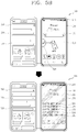
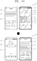
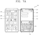
- an icon for performing the capture of the second screen information displayed on the second display may be displayed on the input area, and the capture of the second screen information may be performed at a point in time when a touch input is applied to the icon.
- the input area may include a keyboard area that receives a key input, and a display area on which a result of the received key input is displayed, and, when a touch input is applied to the icon, the controller of the mobile terminal may perform control such that the second screen information is captured and that the captured second screen information is attached to the display area after a fixed time elapsed.
- the first screen information may be a screen corresponding to execution of a message application
- the second screen information may be a screen corresponding to execution of an application different from the first screen information, or a home screen, and, after the captured second screen information is inserted into the input area of the first screen information, the second screen information may also maintain a state of being displayed on the second display.
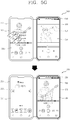
- switching from the second screen information displayed on the second display to an image of the captured second screen information may take place, and a tool area for image editing may be displayed on one area of the image of the captured second screen information for a predetermined time.
- editing of the image of the captured second screen information may be performed based on a touch input that is applied to the tool area, and, in response to an editing completion input applied to the second display, the edited image may be attached to the first display.
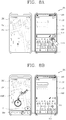
- the controller of the mobile terminal may display an icon for performing the capture of the second screen information included in the input area, in an inactivated state.
- alerting information indicating that the capture is unperformable may be output on the second screen information on the second display.
- the controller of the mobile terminal may perform control such that the second screen information and data associated with execution of an application corresponding to the second screen information are transferred to the second display.
- the transferred second screen information may be captured and be attached to the input area of the first screen information.
- a method of operating an electronic device including a mobile terminal and a case with which the mobile terminal is combined, the mobile terminal including a first display that is combined with the case, and the case being disposed in a second display, the method including: a step of detecting a touch input applied to an input area in a state where first screen information including the input area is displayed on the first display and where second screen information is displayed on the second display; a step of transferring a command to capture the second screen information to the second display, in response to the touch input; and a step of receiving data corresponding to the captured second screen information and inserting the received data into the input area of the first screen information on the first display.
- the method may further include a step of displaying an icon for performing the capture of the second screen information displayed on the second display, on the input area, and of generating the command to capture the second screen information at a point in time when a touch input is applied to the displayed icon.
- the first screen information may be a screen corresponding to execution of a message application
- the second screen information may be a screen corresponding to execution of an application different from the first screen information, or a home screen
- the method may further include a step of continuing to display the second screen information on the second display after the captured second screen information is inserted into the input area.
- the method may further include a step of causing switching from the second screen information displayed on the second display to an image of the captured second screen information to takes place, in response to the reception of the touch input in the input area; and a step of displaying a tool area for image editing, on one area of the image of the captured second screen information for a predetermined time.
- the method may further including a step of performing editing of the image of the captured second screen information based on a touch input that is applied to the tool area within the predetermined time; and a step of inserting the edited image into the input area on the first display, in response to an editing completion input received in the second display.
- a mobile terminal and an electronic device including the mobile terminal according to the present disclosure only with one expanded display conjunction function, screen information that is being output on a different screen is immediately shared as message contents while message conversation is in progress. With a one-time touch input, a user can perform an operation that was performed through various steps. Furthermore, display states of a keyboard area for message inputting and of the screen information that is being output on a different screen are maintained as before. Thus, user convenience and usability are further improved.
- a singular representation may include a plural representation unless it represents a definitely different meaning from the context.
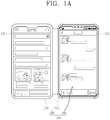
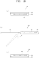
- FIGS. 1A and 1B are conceptual diagrams for describing an electronic device according to the present disclosure.
- a mobile terminal 100 is combined with a case 200, and the mobile terminal 100 is combined with the case 200 to make up one electronic device 300.
- the mobile terminals include a cellular phone, a smart phone, a laptop computer, a digital broadcast terminal, a personal digital assistant (PDA), a portable multimedia player (PMP), a navigation device, a slate PC, a tablet PC, a high-end subnotebook computer, a wearable device (for example, a smartwatch, smart glasses, a head mounted display (HMD)).
- PDA personal digital assistant
- PMP portable multimedia player
- a navigation device for example, a smartwatch, smart glasses, a head mounted display (HMD)
- HMD head mounted display
- the case 200 may be a pouch that protects the appearance of the mobile terminal 100, or covers or accommodates at least one surface of the mobile terminal 100, as an accessory to the mobile terminal 100.
- the case 200 is configured to be combined with the mobile terminal in order to expand a range of functions of the mobile terminal 100.
- information that is output in the mobile terminal is processed in association with a structure or function of the case 200.
- a display hereinafter referred to as a second 250
- a display hereinafter referred to as a first display 151 of the mobile terminal is provided in the case 200.
- the case includes first and second bodies 210 and 220 that are coupled in a manner that is rotatable relative to each other, and the second display 250 is disposed on any one of the first and second bodies 210 and 220.
- the first body 210 is formed to accommodate at least a portion of the body of the mobile terminal.
- a rear side of the mobile terminal is accommodated in the first body 210, and the first display 151 that is disposed on a front side of the mobile terminal is exposed to the outside.
- the mobile terminal 100 is detachably combined with the first body 210.
- the mobile terminal is formed to detect whether or not it is combined with the first body 210.
- a magnet 245 is provided on one surface of the first body 210, which faces the mobile terminal 100.
- a hall sensor 143 which is formed such that a magnetic field corresponding to the magnet 245 is sensed in a case where the body of the mobile terminal is combined with the first body, is included on the rear side of the mobile terminal.
- the hall sensor senses the magnetic field
- the mobile terminal recognizes that the mobile terminal is combined with the case, and performs predetermined control.
- a controller 180 of the mobile terminal 100 controls a power supply unit 190 such that electric current for operation is supplied to the second display 250 that is provided in the second body 220.
- the second display 250 that is provided in the second body 220 is configured to operate on power that is supplied from the mobile terminal 100.
- the second display 250 is disposed in the second body 220 and thus performs a function of expanding a display area of the first display 151 or is driven independently of the first display 151.
- contents associated with information that is output to the first display 151 are mirrored and are output on the second display 250.
- execution screens for different applications are output on the first and second displays 151 and 250, respectively.
- an execution screen for one application is divided into areas and thus that the areas are displayed on the first and second displays 151 and 250, respectively.
- the first and second displays 151 and 250 are exposed together in an open state to the outside, and the open state is defined with reference to FIG. 1B .
- the mobile terminal 100 is configured to control screen information that is output on the second display 250. To do this, at least one of wired and wireless communication links is established between the mobile terminal 100 and the second display 250.
- the mobile terminal 100 is configured such that the electric current for operation is supplied to the second display 250, and the electric current for operation is supplied from the mobile terminal 100 to the second display 250 through a wiring line provided in the case 200.
- the first and second bodies 210 and 220 of the case 200 is rotated relative to each other between a closed state and a full-open state.
- the closed state refers to a state where the first body 210 of the case 200 covers the first display 151 of the mobile terminal 100, as a state that is illustrated in (a) of FIG. 1B , and the first display 151 is hidden by the first body 210. That is, the state where the first display 151 is covered by the second display 250 is the closed state.
- the mobile terminal 100 and the case 200 overlap each other in the thickness direction of the mobile terminal, and thus takes the form of a diary, thereby improving the portability for a user.
- front surfaces of the first and second displays 151 and 250 face each other.
- the front surfaces are external surfaces on which time information is displayed and through which a touch input is received.
- the second body 220 is rotated with respect to the first body 210 in the closed state and thus switches to the open state.
- the open state refers to a state where an angle that the first and second displays 151 and 250 make with respect with each other is a specific angle that is not 0 degrees, as a state where the first display151 is not hidden by the second display 250.
- FIG. 1B illustrates a state where the first and second displays 151 and 250 make an angle of 180 degrees with respect to each other in the open state.
- FIG.1A which is referred to above, illustrates the state where the first and second displays 151 and 250 make an angle of 180 degrees with respect to each other.
- the first and second bodies 210 and 220 are fixed at a specific angle in the open state, and, to do this, a fixation means is provided in the case 220.
- the first and second bodies 210 and 220 are further rotated in an A direction relative to each other. Accordingly, as illustrated in (c) of FIG. 1B , the first and second bodies 210 and 220 are rotated up to 360 degrees relative to each other. Among open states, this state is defined as "full-open state.” In this case, outer surfaces of the first and second bodies 210 and 220 are brought into contact with each other, and the first and second displays 151 and 250 are arranged to face toward the outside. That is, the first and second displays 151 and 250 face in opposite directions.
- the mobile terminal is formed to detect the closed state and the open state.
- the mobile terminal includes an illumination sensor that is configured to sense ambient illumination, and the controller 180 of the mobile terminal 100 senses any one of the closed state and the open state according to illumination that is sensed by the illumination sensor.
- controller 180 separately detects the full-open state that is among the open states.
- An electronic device 300 performs an operation of controlling the first and second displays 151 and 250 in conjunction with the open state and the closed state.
- the first and second displays 151 and 250 are driven in an inactivated state while in the closed state, and in a case where switching from the closed state to the open state takes place, at least one of the first and second displays 151 and 250 is activated.
- both the first and second displays 151 and 250 switch to an activated state.
- different home screen pages are output on the first and second displays 151 and 250, respectively, or the same home screen page is displayed in a divided manner on the first and second displays 151 and 250.
- various pieces of information may be output on the first and second displays 151 and 250.
- the first display 151 switches to the activated state, and the second display 250 maintains the inactivated state.
- the second display 250 includes a touch sensor that is configured to sense a touch which is applied to the second display 250.
- the second display 250 is configured to sense the touch even in the inactivated state.
- the second display 250 is driven in the activated state.
- the second display 250 transfers a touch signal corresponding to the touch, to the mobile terminal 100. Then, in a case where the touch to which the received touch signal corresponds is a predetermined-type touch, the mobile terminal 100 transfers a signal that corresponds to a control command to activate the second display 250, to the second display 250 side.
- a controller of the second display 250 activates the second display 250 based on the signal that is received from the mobile terminal 100.
- the case employs a new structure in order to implement the operation of the electronic device, which is described above.
- the new structure of the case will be described in more detail below.
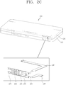
- FIGS. 2A , 2B , and 2C are conceptual diagrams for describing an essential structure of the electronic device according to the present disclosure.
- the first body 210 of the case 200 has an accommodation space 211 that is configured to accommodate a rear surface of the body of the mobile terminal.
- the accommodation space 211 in the first body accommodates at least one portion of the mobile terminal, and the rear surface of the mobile terminal is disposed on a bottom surface of the accommodation space 211.
- the present disclosure is not necessarily limited to this, and for example, the first body in the form of a plate is formed to be combined with the rear surface of the mobile terminal, or is configured to be combined with a flank surface of the mobile terminal.
- the second body 220 in which the second display 250 is disposed is rotatably combined with the first body. That is, the coupling unit 230 is disposed between the first and second bodies 210 and 220 and combines the first and second bodies 210 and 220 such that they is rotatable relative to each other.
- the second body 220 includes a first cover 221, a second cover 222, and the second display 250.
- An accommodation groove 221a in which at least one portion of the coupling unit 230 is accommodated is formed in the first cover 221.
- the second cover 222 is a frame with which the first cover 221 is combined and on which various electronic components are mounted. As an example of this, a second circuit board that will be described below is mounted on the second cover 222.
- the second cover 222 is rotatably combined with the coupling unit 230.
- a groove 222a is formed in a position on the second cover 222, which corresponds to the accommodation groove 221a in the first cover 221.
- the coupling unit 230 is disposed in the groove 222a.
- the second display 250 is mounted on the second cover 222.
- the coupling unit 230 includes first and second hinges 231 and 232 that are arranged apart along a flank surface of the first body 210.
- Each of the first and second hinges 231 and 232 includes a hinge body 233 and a hinge shaft 234.
- a hinge groove (not illustrated) is formed in the hinge body 233.
- the hinge shaft 234 is inserted into the hinge groove, and thus the first and second bodies 210 and 220 are possibly rotated relative to each other.
- a plurality of hinge shafts 234 are provided, and a combining unit 235 that is combined with each of the first and second bodies 210 and 220 is disposed on one side of the hinge shaft 234.
- the case 200 includes a wireless communication unit 283 and a wiring unit 242, and thus, the mobile terminal 100 controls the second display 250.
- the wireless communication unit 283 is disposed in the first body 21 and performs short-range wireless communication with the mobile terminal.
- a wireless communication unit (hereinafter referred to as “second wireless communication”) in the case 200 and a wireless communication unit (hereinafter referred to as “first wireless communication unit”) that performs the short-range wireless communication are arranged in the mobile terminal 100.
- the first wireless communication unit 116 (refer to FIG. 3C ) transmits a wireless signal to the rear side of the mobile terminal 100.
- the second wireless communication unit 283 is disposed in the first body 210 to face the first wireless communication unit 116 and thus receives the wireless signal.
- Each of the first wireless communication unit 116 and the second wireless communication unit 283, for example, include a Keyssa chip that transmits and receives wireless data. Keyssa chips are arranged apart at distances of several centimeters or less along the thickness direction of the mobile terminal. Therefore, using a short-range communication scheme in which a transfer distance is approximately several centimeters, the first wireless communication unit 116 and the second wireless communication unit 283 perform communication.
- the first body 210 includes a first circuit board 243 on which the second wireless communication unit 283 is disposed.
- the second body 210 includes a second circuit board 244 that is disposed under the second display 250 and is electrically coupled to the first circuit board 243 by the wiring unit 242.
- the second circuit board 244 is coupled to the second display 250 and thus performs a function of transferring a control signal received from the mobile terminal 100, to the second display 250.
- the second circuit board 244 transfers data that is transmitted and received between the first wireless communication unit 116 and the second wireless communication unit 283, to the second display 250.
- the wiring unit 242 is a component that electrically couples the first and second bodies 210 and 220 through the coupling unit 230.
- a wireless signal (or data) that is received through the mobile terminal 100 and the short-range wireless communication is transferred to the second display 250 through the wiring unit 242.
- a coupling path along which the wiring unit 242 pass is formed in the coupling unit 230.
- an accommodation space that accommodates at least one portion of the wiring unit 242 is formed in any one of the first and second hinges 231 and 232.
- the first hinge 231 is positioned more toward an upper side of the mobile terminal than the second hinge 232
- the second hinge 232 is positioned more toward a lower side of the mobile terminal 100 than the first hinge 231.
- the second circuit board 244 is disposed adjacent to a lower side end of the case 200, and thus each of the first wireless communication unit 116 and the second wireless communication unit 283 is disposed in the case 200 or under the mobile terminal 100.
- the accommodation space is formed in the second hinge 232.
- the second hinge 232 includes an extension portion 236 that extends from the hinge body 233, and the cable 246 that extends to each of the first body 210 and the second body 220 is provided to the extension portion 236.
- a structure is employed in which the accommodation space is formed in the extension portion 236 and in which the cable 246 is accommodated in the accommodation space.
- First and second flexible printed circuit boards 247 and 248 are positioned at both ends, respectively, of the cable 246, and the first and second flexible printed circuit boards 247 and 248 are electrically coupled to the first and second circuit boards 243 and 244, respectively.
- a signal that controls the second display 250 is transferred in a wireless manner from the mobile terminal to the first body 210 and is transferred in a wired manner to the second body 220.
- a power terminal (for example, a pogo-pin) 249 that is brought into contact with a power supply terminal (not illustrated) of the mobile terminal is disposed on the first circuit board 243 such that power is supplied from the mobile terminal.
- the power terminal 249 is electrically coupled to the wiring unit 242 such that power is supplied to the second display 250.
- the power that is supplied to the second display 250 is transferred through a wired path in the mobile terminal.
- the electronic device performs an operation of controlling the first and second displays 151 and 250 in conjunction with each other, using the short-range wireless communication and a wired path for power supply.
- a structure and a function of the mobile terminal will be described in detail below. Subsequently, the control operation will be described.
- FIGS. 3A , 3B, and 3C are conceptual diagrams for describing an example of a mobile terminal according to the present disclosure.
- the mobile terminal 100 according to the present disclosure is coupled to the case of the electronic device, which is described above.
- Mobile terminals presented herein may be implemented using a variety of different types of terminals. Examples of such terminals include cellular phones, smart phones, user equipment, laptop computers, digital broadcast terminals, personal digital assistants (PDAs), portable multimedia players (PMPs), navigators, portable computers (PCs), slate PCs, tablet PCs, ultra books, wearable devices (for example, smart watches, smart glasses, head mounted displays (HMDs)), and the like.
- PDAs personal digital assistants
- PMPs portable multimedia players
- PCs portable computers
- slate PCs slate PCs
- tablet PCs tablet PCs
- ultra books ultra books
- wearable devices for example, smart watches, smart glasses, head mounted displays (HMDs)
- FIG. 3A is a block diagram of a mobile terminal in accordance with one exemplary embodiment of the present disclosure
- FIGS. 3B and 3C are conceptual diagrams illustrating one example of a mobile terminal, viewed from different directions.
- the mobile terminal 100 may be shown having components such as a wireless communication unit 110, an input unit 120, a sensing unit 140, an output unit 150, an interface unit 160, a memory 170, a controller 180, and a power supply unit 190. It is understood that implementing all of the illustrated components in FIG. 3A is not a requirement, and that greater or fewer components may alternatively be implemented.
- the wireless communication unit 110 may typically include one or more modules which permit communications such as wireless communications between the mobile terminal 100 and a wireless communication system, communications between the mobile terminal 100 and another mobile terminal, or communications between the mobile terminal 100 and an external server. Further, the wireless communication unit 110 may typically include one or more modules which connect the mobile terminal 100 to one or more networks.
- the wireless communication unit 110 may include one or more of a broadcast receiving module 111, a mobile communication module 112, a wireless Internet module 113, a short-range communication module 114, and a location information module 115.
- the input unit 120 may include a camera 121 or an image input unit for obtaining images or video, a microphone 122, which is one type of audio input device for inputting an audio signal, and a user input unit 123 (for example, a touch key, a mechanical key, and the like) for allowing a user to input information.
- Data for example, audio, video, image, and the like
- the sensing unit 140 may typically be implemented using one or more sensors configured to sense internal information of the mobile terminal, the surrounding environment of the mobile terminal, user information, and the like.
- the sensing unit 140 may include at least one of a proximity sensor 141, an illumination sensor 142, a touch sensor, an acceleration sensor, a magnetic sensor, a G-sensor, a gyroscope sensor, a motion sensor, an RGB sensor, an infrared (IR) sensor, a finger scan sensor, a ultrasonic sensor, an optical sensor (for example, camera 121), a microphone 122, a battery gauge, an environment sensor (for example, a barometer, a hygrometer, a thermometer, a radiation detection sensor, a thermal sensor, and a gas sensor, among others), and a chemical sensor (for example, an electronic nose, a health care sensor, a biometric sensor, and the like).
- the mobile terminal disclosed herein may be configured to utilize information obtained from one or more sensors of the sensing unit 140, and combinations thereof.
- the output unit 150 may typically be configured to output various types of information, such as audio, video, tactile output, and the like.
- the output unit 150 may be shown having at least one of a display 151, an audio output module 152, a haptic module 153, and an optical output module 154.
- the display 151 may have an inter-layered structure or an integrated structure with a touch sensor in order to implement a touch screen.
- the touch screen may function as the user input unit 123 which provides an input interface between the mobile terminal 100 and the user and simultaneously provide an output interface between the mobile terminal 100 and a user.
- the interface unit 160 serves as an interface with various types of external devices that are coupled to the mobile terminal 100.
- the interface unit 160 may include any of wired or wireless ports, external power supply ports, wired or wireless data ports, memory card ports, ports for connecting a device having an identification module, audio input/output (I/O) ports, video I/O ports, earphone ports, and the like.
- the mobile terminal 100 may perform assorted control functions associated with a connected external device, in response to the external device being connected to the interface unit 160.
- the memory 170 is typically implemented to store data to support various functions or features of the mobile terminal 100.
- the memory 170 may be configured to store application programs executed in the mobile terminal 100, data or instructions for operations of the mobile terminal 100, and the like. Some of these application programs may be downloaded from an external server via wireless communication. Other application programs may be installed within the mobile terminal 100 at time of manufacturing or shipping, which is typically the case for basic functions of the mobile terminal 100 (for example, receiving a call, placing a call, receiving a message, sending a message, and the like). Application programs may be stored in the memory 170, installed in the mobile terminal 100, and executed by the controller 180 to perform an operation (or function) for the mobile terminal 100.
- the controller 180 typically functions to control an overall operation of the mobile terminal 100, in addition to the operations associated with the application programs.
- the controller 180 may provide or process information or functions appropriate for a user by processing signals, data, information and the like, which are input or output by the aforementioned various components, or activating application programs stored in the memory 170.
- controller 180 may control at least some of the components illustrated in FIG. 3A , to execute an application program that have been stored in the memory 170. In addition, the controller 180 may control at least two of those components included in the mobile terminal 100 to activate the application program.
- the power supply unit 190 may be configured to receive external power or provide internal power in order to supply appropriate power required for operating elements and components included in the mobile terminal 100.
- the power supply unit 190 may include a battery, and the battery may be configured to be embedded in the terminal body, or configured to be detachable from the terminal body.
- At least part of the components may cooperatively operate to implement an operation, a control or a control method of a mobile terminal according to various embodiments disclosed herein. Also, the operation, the control or the control method of the mobile terminal may be implemented on the mobile terminal by an activation of at least one application program stored in the memory 170.
- the broadcast receiving module 111 is typically configured to receive a broadcast signal and/or broadcast associated information from an external broadcast managing entity via a broadcast channel.
- the broadcast channel may include a satellite channel, a terrestrial channel, or both.
- two or more broadcast receiving modules may be utilized to facilitate simultaneous reception of two or more broadcast channels, or to support switching among broadcast channels.
- the mobile communication module 112 can transmit and/or receive wireless signals to and from one or more network entities.
- a network entity include a base station, an external mobile terminal, a server, and the like.
- Such network entities form part of a mobile communication network, which is constructed according to technical standards or communication methods for mobile communications (for example, Global System for Mobile Communication (GSM), Code Division Multi Access (CDMA), CDMA2000 (Code Division Multi Access 2000), EV-DO (Enhanced Voice-Data Optimized or Enhanced Voice-Data Only), Wideband CDMA (WCDMA), High Speed Downlink Packet access (HSDPA), HSUPA (High Speed Uplink Packet Access), Long Term Evolution (LTE) , LTE-A (Long Term Evolution-Advanced), and the like).
- GSM Global System for Mobile Communication
- CDMA Code Division Multi Access
- CDMA2000 Code Division Multi Access 2000
- EV-DO Enhanced Voice-Data Optimized or Enhanced Voice-Data Only
- WCDMA Wideband CDMA
- HSDPA High Speed
- the wireless signal may include various types of data depending on a voice call signal, a video call signal, or a text / multimedia message transmission / reception.
- the wireless Internet module 113 refers to a module for wireless Internet access. This module may be internally or externally coupled to the mobile terminal 100. The wireless Internet module 113 may transmit and/or receive wireless signals via communication networks according to wireless Internet technologies.
- wireless Internet access examples include Wireless LAN (WLAN), Wireless Fidelity (Wi-Fi), Wi-Fi Direct, Digital Living Network Alliance (DLNA), Wireless Broadband (WiBro), Worldwide Interoperability for Microwave Access (WiMAX), High Speed Downlink Packet Access (HSDPA), High Speed Uplink Packet Access (HSUPA), Long Term Evolution (LTE), LTE-advanced (LTE-A) and the like.
- the wireless Internet module 113 may transmit/receive data according to one or more of such wireless Internet technologies, and other Internet technologies as well.
- the wireless Internet module 113 When the wireless Internet access is implemented according to, for example, WiBro, HSDPA, HSUPA, GSM, CDMA, WCDMA, LTE, LTE-A and the like, as part of a mobile communication network, the wireless Internet module 113 performs such wireless Internet access. As such, the Internet module 113 may cooperate with, or function as, the mobile communication module 112.
- the short-range communication module 114 is configured to facilitate short-range communications. Suitable technologies for implementing such short-range communications include BLUETOOTHTM, Radio Frequency IDentification (RFID), Infrared Data Association (IrDA), Ultra-WideBand (UWB), ZigBee, Near Field Communication (NFC), Wireless-Fidelity (Wi-Fi), Wi-Fi Direct, Wireless USB (Wireless Universal Serial Bus), and the like.
- the short-range communication module 114 in general supports wireless communications between the mobile terminal 100 and a wireless communication system, communications between the mobile terminal 100 and another mobile terminal 100, or communications between the mobile terminal and a network where another mobile terminal 100 (or an external server) is located, via wireless area networks.
- One example of the wireless area networks is a wireless personal area networks.
- another mobile terminal (which may be configured similarly to mobile terminal 100) may be a wearable device, for example, a smart watch, a smart glass or a head mounted display (HMD), which is able to exchange data with the mobile terminal 100 (or otherwise cooperate with the mobile terminal 100).
- the short-range communication module 114 may sense or recognize the wearable device, and permit communication between the wearable device and the mobile terminal 100.
- the controller 180 when the sensed wearable device is a device which is authenticated to communicate with the mobile terminal 100, the controller 180, for example, may cause transmission of at least part of data processed in the mobile terminal 100 to the wearable device via the short-range communication module 114.
- a user of the wearable device may use the data processed in the mobile terminal 100 on the wearable device. For example, when a call is received in the mobile terminal 100, the user may answer the call using the wearable device. Also, when a message is received in the mobile terminal 100, the user can check the received message using the wearable device.
- the location information module 115 is generally configured to detect, calculate, derive or otherwise identify a position (or current position) of the mobile terminal.
- the location information module 115 includes a Global Position System (GPS) module, a Wi-Fi module, or both.
- GPS Global Position System
- Wi-Fi Wireless Fidelity
- a position of the mobile terminal may be acquired using a signal sent from a GPS satellite.
- AP wireless access point
- the location information module 115 may alternatively or additionally function with any of the other modules of the wireless communication unit 110 to obtain data related to the position of the mobile terminal.
- the location information module 115 is a module used for acquiring the position (or the current position) and may not be limited to a module for directly calculating or acquiring the position of the mobile terminal.
- Image and video input is often obtained using one or more cameras 121.
- Such cameras 121 may process image frames of still pictures or video obtained by image sensors in a video or image capture mode. The processed image frames can be displayed on the display 151 or stored in memory 170.
- the cameras 121 may be arranged in a matrix configuration to permit a plurality of images having various angles or focal points to be input to the mobile terminal 100.
- the cameras 121 may be located in a stereoscopic arrangement to acquire left and right images for implementing a stereoscopic image.
- the microphone 122 processes an external audio signal into electric audio (sound) data.
- the processed audio data can be processed in various manners according to a function being executed in the mobile terminal 100. If desired, the microphone 122 may include assorted noise removing algorithms to remove unwanted noise generated in the course of receiving the external audio signal.
- the user input unit 123 is a component that permits input by a user. Such user input may enable the controller 180 to control operation of the mobile terminal 100.
- the user input unit 123 may include one or more of a mechanical input element (for example, a mechanical key, a button located on a front and/or rear surface or a side surface of the mobile terminal 100, a dome switch, a jog wheel, a jog switch, and the like), or a touch-sensitive input element, among others.
- the touch-sensitive input element may be a virtual key, a soft key or a visual key, which is displayed on a touch screen through software processing, or a touch key which is located on the mobile terminal at a location that is other than the touch screen.
- the virtual key or the visual key may be displayed on the touch screen in various shapes, for example, graphic, text, icon, video, or a combination thereof.
- the sensing unit 140 is generally configured to sense one or more of internal information of the mobile terminal, surrounding environment information of the mobile terminal, user information, or the like, and generate a corresponding sensing signal.
- the controller 180 generally cooperates with the sending unit 140 to control operations of the mobile terminal 100 or execute data processing, a function or an operation associated with an application program installed in the mobile terminal based on the sensing signal.
- the sensing unit 140 may be implemented using any of a variety of sensors, some of which will now be described in more detail.
- the proximity sensor 141 refers to a sensor to sense presence or absence of an object approaching a surface, or an object located near a surface, by using an electromagnetic field, infrared rays, or the like without a mechanical contact.
- the proximity sensor 141 may be arranged at an inner area of the mobile terminal covered by the touch screen, or near the touch screen.
- the proximity sensor 141 can sense proximity of a pointer relative to the touch screen by changes of an electromagnetic field, which is responsive to an approach of an object with conductivity.
- the proximity sensor 141 can sense proximity of a pointer relative to the touch screen by changes of an electromagnetic field, which is responsive to an approach of an object with conductivity.
- the touch screen may also be categorized as a proximity sensor.
- proximity touch will often be referred to herein to denote the scenario in which a pointer is positioned to be proximate to the touch screen without contacting the touch screen.
- contact touch will often be referred to herein to denote the scenario in which a pointer makes physical contact with the touch screen.
- the proximity sensor 141 may sense proximity touch, and proximity touch patterns (for example, distance, direction, speed, time, position, moving status, and the like).
- controller 180 processes data corresponding to proximity touches and proximity touch patterns sensed by the proximity sensor 141, and cause output of visual information on the touch screen.
- the controller 180 can control the mobile terminal 100 to execute different operations or process different data (or information) according to whether a touch with respect to a point on the touch screen is either a proximity touch or a contact touch.
- a touch sensor senses a touch (or a touch input) applied to the touch screen (or the display 151) using any of a variety of touch methods. Examples of such touch methods include a resistive type, a capacitive type, an infrared type, and a magnetic field type, among others.
- the touch sensor may be configured to convert changes of pressure applied to a specific part of the display 151, or convert capacitance occurring at a specific part of the display 151, into electric input signals.
- the touch sensor may also be configured to sense not only a touched position and a touched area, but also touch pressure and/or touch capacitance.
- a touch object is generally used to apply a touch input to the touch sensor. Examples of typical touch objects include a finger, a touch pen, a stylus pen, a pointer, or the like.
- a touch controller When a touch input is sensed by a touch sensor, corresponding signals may be transmitted to a touch controller.
- the touch controller may process the received signals, and then transmit corresponding data to the controller 180. Accordingly, the controller 180 may sense which area of the display 151 has been touched.
- the touch controller may be a component separate from the controller 180, the controller 180, and combinations thereof.
- the controller 180 may execute the same or different controls according to a type of touch object that touches the touch screen or a touch key provided in addition to the touch screen. Whether to execute the same or different control according to the object which provides a touch input may be decided based on a current operating state of the mobile terminal 100 or a currently executed application program, for example.
- the touch sensor and the proximity sensor may be implemented individually, or in combination, to sense various types of touches.
- Such touches include a short (or tap) touch, a long touch, a multi-touch, a drag touch, a flick touch, a pinch-in touch, a pinch-out touch, a swipe touch, a hovering touch, and the like.
- an ultrasonic sensor may be implemented to recognize location information relating to a touch object using ultrasonic waves.
- the controller 180 may calculate a position of a wave generation source based on information sensed by an illumination sensor and a plurality of ultrasonic sensors. Since light is much faster than ultrasonic waves, the time for which the light reaches the optical sensor is much shorter than the time for which the ultrasonic wave reaches the ultrasonic sensor. The position of the wave generation source may be calculated using this fact. For instance, the position of the wave generation source may be calculated using the time difference from the time that the ultrasonic wave reaches the sensor based on the light as a reference signal.
- the camera 121 which has been depicted as a component of the input unit 120, typically includes at least one a camera sensor (CCD, CMOS etc.), a photo sensor (or image sensors), and a laser sensor.
- a camera sensor CCD, CMOS etc.
- a photo sensor or image sensors
- a laser sensor
- the photo sensor may be laminated on, or overlapped with, the display device.
- the photo sensor may be configured to scan movement of the physical object in proximity to the touch screen.
- the photo sensor may include photo diodes and transistors (TRs) at rows and columns to scan content received at the photo sensor using an electrical signal which changes according to the quantity of applied light.
- the photo sensor may calculate the coordinates of the physical object according to variation of light to thus obtain location information of the physical object.
- the display 151 is generally configured to output information processed in the mobile terminal 100.
- the display 151 may display execution screen information of an application program executing at the mobile terminal 100 or user interface (Ul) and graphic user interface (GUI) information in response to the execution screen information.
- User user interface
- GUI graphic user interface
- the display 151 may be implemented as a stereoscopic display for displaying stereoscopic images.
- a typical stereoscopic display may employ a stereoscopic display scheme such as a stereoscopic scheme (a glass scheme), an auto-stereoscopic scheme (glassless scheme), a projection scheme (holographic scheme), or the like.
- a stereoscopic display scheme such as a stereoscopic scheme (a glass scheme), an auto-stereoscopic scheme (glassless scheme), a projection scheme (holographic scheme), or the like.
- the audio output module 152 may receive audio data from the wireless communication unit 110 or output audio data stored in the memory 170 during modes such as a signal reception mode, a call mode, a record mode, a voice recognition mode, a broadcast reception mode, and the like.
- the audio output module 152 can provide audible output related to a particular function (e.g., a call signal reception sound, a message reception sound, etc.) performed by the mobile terminal 100.
- the audio output module 152 may also be implemented as a receiver, a speaker, a buzzer, or the like.
- a haptic module 153 can be configured to generate various tactile effects that a user feels, perceives, or otherwise experiences.
- a typical example of a tactile effect generated by the haptic module 153 is vibration.
- the strength, pattern and the like of the vibration generated by the haptic module 153 can be controlled by user selection or setting by the controller. For example, the haptic module 153 may output different vibrations in a combining manner or a sequential manner.
- the haptic module 153 can generate various other tactile effects, including an effect by stimulation such as a pin arrangement vertically moving to contact skin, a spray force or suction force of air through a jet orifice or a suction opening, a touch to the skin, a contact of an electrode, electrostatic force, an effect by reproducing the sense of cold and warmth using an element that can absorb or generate heat, and the like.
- an effect by stimulation such as a pin arrangement vertically moving to contact skin, a spray force or suction force of air through a jet orifice or a suction opening, a touch to the skin, a contact of an electrode, electrostatic force, an effect by reproducing the sense of cold and warmth using an element that can absorb or generate heat, and the like.
- the haptic module 153 can also be implemented to allow the user to feel a tactile effect through a muscle sensation such as the user's fingers or arm, as well as transferring the tactile effect through direct contact. Two or more haptic modules 153 may be provided according to the particular configuration of the mobile terminal 100.
- An optical output module 154 can output a signal for indicating an event generation using light of a light source. Examples of events generated in the mobile terminal 100 may include message reception, call signal reception, a missed call, an alarm, a schedule notice, an email reception, information reception through an application, and the like.
- a signal output by the optical output module 154 may be implemented such that the mobile terminal emits monochromatic light or light with a plurality of colors.
- the signal output may be terminated as the mobile terminal senses that a user has checked the generated event, for example.
- the interface unit 160 serves as an interface for external devices to be connected with the mobile terminal 100.
- the interface unit 160 can receive data transmitted from an external device, receive power to transfer to elements and components within the mobile terminal 100, or transmit internal data of the mobile terminal 100 to such external device.
- the interface unit 160 may include wired or wireless headset ports, external power supply ports, wired or wireless data ports, memory card ports, ports for connecting a device having an identification module, audio input/output (I/O) ports, video I/O ports, earphone ports, or the like.
- the identification module may be a chip that stores various information for authenticating authority of using the mobile terminal 100 and may include a user identity module (UIM), a subscriber identity module (SIM), a universal subscriber identity module (USIM), and the like.
- the device having the identification module (also referred to herein as an "identifying device") may take the form of a smart card. Accordingly, the identifying device can be connected with the terminal 100 via the interface unit 160.
- the interface unit 160 can serve as a passage to allow power from the cradle to be supplied to the mobile terminal 100 or may serve as a passage to allow various command signals input by the user from the cradle to be transferred to the mobile terminal therethrough.
- Various command signals or power input from the cradle may operate as signals for recognizing that the mobile terminal is properly mounted on the cradle.
- the memory 170 can store programs to support operations of the controller 180 and store input/output data (for example, phonebook, messages, still images, videos, etc.).
- the memory 170 may store data related to various patterns of vibrations and audio which are output in response to touch inputs on the touch screen.
- the memory 170 may include one or more types of storage mediums including a flash memory type, a hard disk type, a solid state disk (SSD) type, a silicon disk drive (SDD) type, a multimedia card micro type, a card-type memory (e.g., SD or DX memory, etc.), a Random Access Memory (RAM), a Static Random Access Memory (SRAM), a Read-Only Memory (ROM), an Electrically Erasable Programmable Read-Only Memory (EEPROM), a Programmable Read-Only memory (PROM), a magnetic memory, a magnetic disk, an optical disk, and the like.
- the mobile terminal 100 may also be operated in relation to a network storage device that performs the storage function of the memory 170 over a network, such as the Internet.
- the controller 180 may typically control operations relating to application programs and the general operations of the mobile terminal 100. For example, the controller 180 may set or release a lock state for restricting a user from inputting a control command with respect to applications when a status of the mobile terminal meets a preset condition.
- the controller 180 can also perform the controlling and processing associated with voice calls, data communications, video calls, and the like, or perform pattern recognition processing to recognize a handwriting input or a picture drawing input performed on the touch screen as characters or images, respectively.
- the controller 180 can control one or a combination of those components in order to implement various exemplary embodiments disclosed herein.
- the power supply unit 190 receives external power or provides internal power and supply the appropriate power required for operating respective elements and components included in the wearable device 100 under the control of the controller 180.
- the power supply unit 190 may include a battery, which is typically rechargeable or be detachably coupled to the terminal body for charging.
- the power supply unit 190 may include a connection port.
- the connection port may be configured as one example of the interface unit 160 to which an external charger for supplying power to recharge the battery is electrically connected.
- the power supply unit 190 may be configured to recharge the battery in a wireless manner without use of the connection port.
- the power supply unit 190 can receive power, transferred from an external wireless power transmitter, using at least one of an inductive coupling method which is based on magnetic induction or a magnetic resonance coupling method which is based on electromagnetic resonance.
- Various embodiments described herein may be implemented in a computer-readable medium, a machine-readable medium, or similar medium using, for example, software, hardware, or any combination thereof.
- the disclosed mobile terminal 100 includes a bar-like terminal body.
- the mobile terminal 100 may alternatively be implemented in any of a variety of different configurations. Examples of such configurations include watch type, clip-type, glasses-type, or a folder-type, flip-type, slide-type, swing-type, and swivel-type in which two and more bodies are combined with each other in a relatively movable manner, and combinations thereof. Discussion herein will often relate to a particular type of mobile terminal. However, such teachings with regard to a particular type of mobile terminal will generally apply to other types of mobile terminals as well.
- the terminal body may be understood as a conception referring to the assembly.
- the mobile terminal 100 will generally include a case (for example, frame, housing, cover, and the like) forming the appearance of the terminal.
- the case is formed using a front case 101 and a rear case 102.
- Various electronic components are interposed into a space formed between the front case 101 and the rear case 102.
- At least one middle case may be additionally positioned between the front case 101 and the rear case 102.
- the display 151 is shown located on the front side of the terminal body to output information. As illustrated, a window 151a of the display 151 may be mounted to the front case 101 to form the front surface of the terminal body together with the front case 101.
- electronic components may also be mounted to the rear case 102.
- electronic components include a detachable battery 191, an identification module, a memory card, and the like.
- a rear cover 103 is shown covering the electronic components, and this cover may be detachably coupled to the rear case 102. Therefore, when the rear cover 103 is detached from the rear case 102, the electronic components mounted on the rear case 102 are exposed to the outside.
- the rear cover 103 when the rear cover 103 is coupled to the rear case 102, a side surface of the rear case 102 may partially be exposed. In some cases, upon the coupling, the rear case 102 may also be completely shielded by the rear cover 103. Meanwhile, the rear cover 103 may include an opening for externally exposing a camera 121b or an audio output module 152b.
- the cases 101, 102, 103 may be formed by injection-molding synthetic resin or may be formed of a metal, for example, stainless steel (STS), aluminum (Al), titanium (Ti), or the like.
- STS stainless steel
- Al aluminum
- Ti titanium
- the mobile terminal 100 may be configured such that one case forms the inner space.
- a mobile terminal 100 having a uni-body is formed such that synthetic resin or metal extends from a side surface to a rear surface.
- the mobile terminal 100 may include a waterproofing unit (not shown) for preventing introduction of water into the terminal body.
- the waterproofing unit may include a waterproofing member which is located between the window 151a and the front case 101, between the front case 101 and the rear case 102, or between the rear case 102 and the rear cover 103, to hermetically seal an inner space when those cases are coupled.
- the mobile terminal 100 may include a display 151, first and second audio output module 152a and 152b, a proximity sensor 141, an illumination sensor 142, an optical output module 154, first and second cameras 121a and 121b, first and second manipulation units 123a and 123b, a microphone 122, an interface unit 160, and the like.
- the exemplary mobile terminal 100 in which the front surface of the terminal body is shown having the display 151, the first audio output module 152a, the proximity sensor 141, the illumination sensor 142, the optical output module 154, the first camera 121a, and the first manipulation unit 123a, the side surface of the terminal body is shown having the second manipulation unit 123b, the microphone 122, and the interface unit 160, and the rear surface of the terminal body is shown having the second audio output module 152b and the second camera 121b.
- those components may not be limited to the arrangement. Some components may be omitted or rearranged or located on different surfaces.
- the first manipulation unit 123a may be located on another surface of the terminal body
- the second audio output module 152b may be located on the side surface of the terminal body other than the rear surface of the terminal body.
- the display 151 is generally configured to output information processed in the mobile terminal 100.
- the display 151 may display execution screen information of an application program executing at the mobile terminal 100 or user interface (Ul) and graphic user interface (GUI) information in response to the execution screen information.
- User user interface
- GUI graphic user interface
- the display module 151 may include at least one of a liquid crystal display (LCD), a thin film transistor-LCD (TFT LCD), an organic light-emitting diode (OLED), a flexible display, a three-dimensional (3D) display and an e-ink display.
- LCD liquid crystal display
- TFT LCD thin film transistor-LCD
- OLED organic light-emitting diode
- flexible display a three-dimensional (3D) display and an e-ink display.
- the display 151 may be implemented using two display devices, according to the configuration type thereof. For instance, a plurality of the displays 151 may be arranged on one side, either spaced apart from each other, or these devices may be integrated, or these devices may be arranged on different surfaces.
- the display 151 may include a touch sensor that senses a touch with respect to the display 151 so as to receive a control command in a touch manner. Accordingly, when a touch is applied to the display 151, the touch sensor may sense the touch, and a controller 180 may generate a control command corresponding to the touch. Contents input in the touch manner may be characters, numbers, instructions in various modes, or a menu item that can be specified.
- the touch sensor may be configured in a form of a film having a touch pattern and disposed between a window 151a and a display (not illustrated) on a rear surface of the window, or may be a metal wire directly patterned on the rear surface of the window.
- the touch sensor may be formed integrally with the display.
- the touch sensor may be disposed on a substrate of the display, or may be provided inside the display.
- the display 151 may form a touch screen together with the touch sensor, and in this case, the touch screen may function as the user input unit (123, see FIG. 3A ). In some cases, the touch screen may replace at least some of functions of a first manipulation unit 123a.
- the first audio output module 152a may be implemented as a receiver for transmitting a call sound to a user's ear and the second audio output module 152b may be implemented as a loud speaker for outputting various alarm sounds or multimedia reproduction request sounds.
- the window 151a of the display 151 may include a sound hole for emitting sounds generated from the first audio output module 152a.
- the present disclosure is not limited thereto, and the sounds may be released along an assembly gap between the structural bodies (for example, a gap between the window 151a and the front case 101).
- a hole independently formed to output audio sounds may not be seen or may otherwise be hidden in terms of appearance, thereby further simplifying the appearance of the mobile terminal 100.
- the optical output module 154 may be configured to output light for indicating an event generation. Examples of such events may include a message reception, a call signal reception, a missed call, an alarm, a schedule alarm, an email reception, information reception through an application, and the like.
- the controller 180 may control the optical output module 154 to stop the light output.
- the first camera 121a may process image frames such as still or moving images obtained by the image sensor in a capture mode or a video call mode. The processed image frames can then be displayed on the display 151 or stored in the memory 170.
- the first and second manipulation units 123a and 123b are examples of the user input unit 123, which may be manipulated by a user to provide input to the mobile terminal 100.
- the first and second manipulation units 123a and 123b may also be commonly referred to as a manipulating portion.
- the first and second manipulation units 123a and 123b may employ any method if it is a tactile manner allowing the user to perform manipulation with a tactile feeling such as touch, push, scroll or the like.
- the first and second manipulation units 123a and 123b may also be manipulated through a proximity touch, a hovering touch, and the like, without a user's tactile feeling.
- first manipulation unit 123a is a touch key, but the present disclosure may not be necessarily limited to this.
- the first manipulation unit 123a may be configured with a mechanical key, or a combination of a touch key and a push key.
- the content received by the first and second manipulation units 123a and 123b may be set in various ways.
- the first manipulation unit 123a may be used by the user to input a command such as menu, home key, cancel, search, or the like
- the second manipulation unit 123b may be used by the user to input a command, such as controlling a volume level being output from the first or second audio output module 152a or 152b, switching into a touch recognition mode of the display 151, or the like.
- a rear input unit (not shown) may be disposed on the rear surface of the terminal body.
- the rear input unit may be manipulated by a user to input a command for controlling an operation of the mobile terminal 100.
- the content input may be set in various ways.
- the rear input unit may be used by the user to input a command, such as power on/off, start, end, scroll or the like, controlling a volume level being output from the first or second audio output module 152a or 152b, switching into a touch recognition mode of the display 151, or the like.
- the rear input unit may be implemented into a form allowing a touch input, a push input or a combination thereof.
- the rear input unit may be disposed to overlap the display 151 of the front surface in a thickness direction of the terminal body.
- the rear input unit may be disposed on an upper end portion of the rear surface of the terminal body such that a user can easily manipulate it using a forefinger when the user grabs the terminal body with one hand.
- the present disclosure may not be limited to this, and the position of the rear input unit may be changeable.
- a new user interface may be implemented using the rear input unit.
- the aforementioned touch screen or the rear input unit may substitute for at least part of functions of the first manipulation unit 123a located on the front surface of the terminal body. Accordingly, when the first manipulation unit 123a is not disposed on the front surface of the terminal body, the display 151 may be implemented to have a larger screen.
- the mobile terminal 100 may include a finger scan sensor which scans a user's fingerprint.
- the controller may use fingerprint information sensed by the finger scan sensor as an authentication means.
- the finger scan sensor may be installed in the display 151 or the user input unit 123.
- the microphone 122 may be configured to receive the user's voice, other sounds, and the like.
- the microphone 122 may be provided at a plurality of places, and configured to receive stereo sounds.
- the interface unit 160 may serve as a path allowing the mobile terminal 100 to interface with external devices.
- the interface unit 160 may be at least one of a connection terminal for connecting to another device (for example, an earphone, an external speaker, or the like), a port for near field communication (for example, an Infrared DaAssociation (IrDA) port, a Bluetooth port, a wireless LAN port, and the like), or a power supply terminal for supplying power to the mobile terminal 100.
- the interface unit 160 may be implemented in the form of a socket for accommodating an external card, such as Subscriber Identification Module (SIM), User Identity Module (UIM), or a memory card for information storage.
- SIM Subscriber Identification Module
- UIM User Identity Module
- the second camera 121b may be further mounted to the rear surface of the terminal body.
- the second camera 121b may have an image capturing direction, which is substantially opposite to the direction of the first camera unit 121a.
- the second camera 121b may include a plurality of lenses arranged along at least one line.
- the plurality of lenses may be arranged in a matrix form.
- the cameras may be referred to as an 'array camera.' When the second camera 121b is implemented as the array camera, images may be captured in various manners using the plurality of lenses and images with better qualities may be obtained.
- the flash 124 may be disposed adjacent to the second camera 121b. When an image of a subject is captured with the camera 121b, the flash 124 may illuminate the subject.
- the second audio output module 152b may further be disposed on the terminal body.
- the second audio output module 152b may implement stereophonic sound functions in conjunction with the first audio output module 152a, and may be also used for implementing a speaker phone mode for call communication.
- At least one antenna for wireless communication may be disposed on the terminal body.
- the antenna may be embedded in the terminal body or formed in the case.
- an antenna which configures a part of the broadcast receiving module 111 may be retractable into the terminal body.
- an antenna may be formed in a form of film to be attached onto an inner surface of the rear cover 103 or a case including a conductive material may serve as an antenna.
- the terminal body is provided with a power supply unit 190 (see FIG. 3A ) for supplying power to the mobile terminal 100.
- the power supply unit 190 may include a batter 191 which is mounted in the terminal body or detachably coupled to an outside of the terminal body.
- the battery 191 may receive power via a power cable connected to the interface unit 160. Also, the battery 191 may be (re)chargeable in a wireless manner using a wireless charger.
- the wireless charging may be implemented by magnetic induction or electromagnetic resonance.
- the drawing illustrates that the rear cover 103 is coupled to the rear case 102 for shielding the battery 191, so as to prevent separation of the battery 191 and protect the battery 191 from an external impact or foreign materials.
- the rear case 103 may be detachably coupled to the rear case 102.
- An accessory for protecting an appearance or assisting or expanding the functions of the mobile terminal 100 may further be provided on the mobile terminal 100.
- a cover or pouch for covering or accommodating at least one surface of the mobile terminal 100 may be provided.
- the cover or pouch may cooperate with the display 151 to expand the function of the mobile terminal 100.
- Another example of the accessory may be a touch pen for assisting or expanding a touch input onto a touch screen.
- the electronic device 300 is configured such that a first wireless communication unit 116 (refer to FIG. 3C ) provided on the rear side of the mobile terminal and a second wireless communication unit 283 provided in the first body 210 of the case 200 perform data communication with each other.
- a method of performing the data communication between the first and second wireless communication units 116 and 283 will be described in more detail below with reference to the accompanying drawings.
- FIG. 4 is a conceptual diagram for describing a method of control between the displays that are provided in the mobile terminal and the case, respectively, in the electronic device according to the present disclosure.
- the mobile terminal 100 is combined with the first body 210, and, in a case where the mobile terminal 100 is combined with the first body 210, the first and second wireless communication units 116 and 283 are configured to face each other.
- the first wireless communication unit 116 that is provided in the mobile terminal 100 is included in the wireless communication unit 110 that is described above with reference to FIG. 3A .
- the wireless communication unit 110 of the mobile terminal 100 is configured to be made up of a plurality of wireless communication units, and the plurality of wireless communication units are arranged in different positions, respectively, in the mobile terminal 100.
- the first wireless communication unit 116 is provided on the rear side of the mobile terminal 100, and thus, in a case where the mobile terminal 100 is combined with the first body 210, is configured to perform the data communication with the second wireless communication unit 283 provided in the first body 210.
- the first and second wireless communication units 116 and 283 according to the present disclosure are each configured with contactless connectors for the data communication.
- the contactless connectors as electromagnetic connectors that form electromagnetic communication links, are arranged in different devices, respectively, and thus, electromagnetic communication links are established.
- the first and second wireless communication units 116 and 283 are each configured with transceivers for converting electric signals into EM signals.
- the transceiver of one of the first and second wireless communication unit 116 and 283 converts electric signals into EM signals.
- the EM signals are received by a different transceiver, and the different transceiver converts the EM signals into electric signals.
- the term "transceiver” refers to a device, such as an integrated circuit (IC) that includes a transmitter (Tx) and a receiver (Rx) such that the IC is used for transmitting and receiving information (data).
- IC integrated circuit
- the transceiver is operable in a half-duplex mode (transmission and reception are alternately performed) and a full-duplex mode (transmission and reception are concurrently performed) or is configured as any one of a transmitter and a receiver.
- the transceiver includes separate integrated circuits for a transmission function and a reception function.
- contactless is used to refer to realization of electromagnetic (EM) connection and signal transfer rather than electricity (along a wired line or through contact) between the first and second wireless communication units 116 and 283.
- EM electromagnetic
- contactless refers to a carrier-assisted, dielectric coupling system that is capable of having an optimal range at a distance ranging from 0 to 5 centimeters.
- the connection is verified by the proximity of one of the first and second wireless communication units 116 and 283 to the other.
- Many contactless transmitters and receivers occupy a small space.
- the contactless link that is established in an electromagnetic (EM) manner is a point-to-point link.
- the first and second wireless communication units 116 and 283 each make a wired connection in order to transmit data from one position to another position, or form a point-to-point contactless communication link or a coupled-pair that does not need a physically wired connection.
- the transceivers are extremely high frequency (EHF) transceivers.
- the first wireless communication unit 116 of the mobile terminal 100 and the second wireless communication unit 283 in the first body 210 are configured to face each other and are configured to be positioned within a predetermined distance. Therefore, the contactless communication link is formed between the first and second wireless communication units 116 and 283.
- Data is transmitted between the mobile terminal 100 and the second display 250 through the EHF transceivers that are included in the first and second wireless communication units 116 and 283, respectively.
- the second wireless communication unit 283 that transmits and receives data to and from the second display 250, that is, the EFH transceiver, as described with reference to FIGS. 2A , 2B , and 2C , is provided in the first body 210.
- the second wireless communication unit 283 provided in the first body 210 is configured to transmit and receive data in a wired manner to and from the second display 250 through the wiring unit 242 included in the coupling unit 230.
- the mobile terminal 100 is combined with the first body 210, and thus the EHF transceivers that are included in the first and second wireless communication units 116 and 283, respectively, are combined, in proximity, with each other.
- the coupled-pair of the EHF transceivers of each of the first and second wireless communication units 116 and 283 provides a contactless data route, path, or channel.
- data paths are unidirectional (for example, a flow of data from the mobile terminal 100 to the second display 250 over a specific path) or are bidirectional (for example, a bidirectional flow of data between the mobile terminal 100 and the second display 150 over a specific path).
- the first and second wireless communication units 116 and 283 are configured in such a manner as to transmit and receive various types of data.
- various types of data include graphical data, audio data, video data, touch event data, and a combination of these.
- the second display 250 provided on the second body 220 is configured to operate on power that is supplied from the mobile terminal 100.
- the power at this time is supplied up to the second display 250 through the wiring unit 242 provided on the first circuit board 243 and the coupling unit 230 that are electrically connected to the mobile terminal 100, and through an electrical coupling path to the second circuit board 244 provided in the second body 220.
- a power supply unit 191 of the mobile terminal 100 is configured to supply electric current (or power) for operation to a power supply unit 291 of the second display 250 through the wiring unit 242 provided on the first circuit board 243 and the coupling unit 230, and through the electrical coupling path to the second circuit board 244 provided in the second body 220.
- the mobile terminal 100 is detachably combined with the first body 210.
- the mobile terminal is formed to detect whether or not it is combined with the first body 210.
- a magnet 245 is provided on one surface of the first body 210, which faces the mobile terminal 100.
- a hall sensor 143 which is formed such that a magnetic field corresponding to the magnet 245 is sensed in a case where the body of the mobile terminal is combined with the first body, is included on the rear side of the mobile terminal.
- the hall sensor senses the magnetic field
- the mobile terminal recognizes that the mobile terminal is combined with the case, and performs predetermined control.
- a controller 180 of the mobile terminal 100 controls a power supply unit 190 such that the electric current for operation is supplied to the second display 250 provided in the second body 220.
- the second display 250 provided in the second body 220 is configured to operate on the power that is supplied from the mobile terminal 100.
- the second display 250 is in any one of the activated state and the inactivated state, and even in a state where the second display 250 is in the inactivated state, a touch sensor (or a touch panel 252) provided in the second display 250 is configured to be driven in the activated state and to sense a touch that is applied to the second display 250.
- a touch sensor or a touch panel 252 provided in the second display 250 is configured to be driven in the activated state and to sense a touch that is applied to the second display 250.
- the mobile terminal 100 transfers screen information (or a digital image signal) that is to be output on a display 251 provided in the second display 250, to the second wireless communication unit 283 side, through the first wireless communication unit 116.
- the image signal at this time is transferred as a signal in a frequency band of 60 GHz in a wireless manner through a wireless connector.
- the second display 250 receives data (for example, a digital image signal or the like) from the first wireless communication unit 116 through the second wireless communication unit 283 and the second circuit board 244. At this time, the digital image signal is converted by a data conversion unit 282 into data in a format that is possibly output on the second display 250.
- the second display 250 is configured with an LCD panel.
- a digital image signal in DP format which is received from the mobile terminal 100, is converted by the data conversion unit 282 into a data format (a MIPI format) that is receivable by the LCD panel and is transferred and output to and on the display 251.
- types of pieces of data is predetermined that are transmitted and received through the first and second wireless communication units 116 and 283. For example, only data that corresponds to an image signal is transmitted and received through the first and second wireless communication units 116 and 283.
- signals necessary for transfer between the mobile terminal 100 and the second display 250 such as a communication control signal, a touch signal, and a brightness control signal, except for the image signal, go through the first and second signal processing units 181 and 281 through a multiple-input channel and then are transmitted and received through the first circuit board 243 and the power terminal (for example, the pogo-pin) 249.
- initialization or the like of the second display 250 is controlled by the controller included in the second display 250.
- a method of screen control between the first display and the second display provided in the mobile terminal and the case, respectively, of the electronic device 300 according to the present disclosure will be described in more detail below with reference to FIGS. 5A to 5H .
- the first display 151 provided in the mobile terminal 100 is in the activated state
- the second display 250 provided in the case 200 is in the inactivated state.
- the first display 151 is in the activated state, and for example, a home screen 510 is output.
- the electric current for operation is supplied to the second display 250, but the inactivated state is maintained until an input is applied.
- the input here is an input that wakes up the second display 250, and for example, is a touch input (for example, a tap or a double tap, which is hereinafter referred to as a "knocking function") that is applied to the second display 250.
- a touch signal that corresponds to the touch input is transferred to the first wireless communication unit 116 through the second wireless communication unit 283 ( FIG. 4 ). Then, the controller 180 of the mobile terminal determines whether or not the touch signal received through the first wireless communication unit corresponds to a predetermined-type touch. In a case where a result of the determination is that the touch signal is a signal that corresponds to the predetermined-type touch (for example, the tap or the double tap), a control signal that causes the second display 250 to switch to the activated state is generated and is transferred to the second display 250 through the first wireless communication unit 116 and the second wireless communication unit 283.
- both the first display 151 and the second display 250 are in the activated state.
- a first home screen is output on the first display 151
- a second home screen different from the first home screen, or a given screen is output on the second display 250.
- an icon 520 indicating that a menu associated with control of the second display 250 is hidden is displayed on one area, for example, an edge area, of the home screen 510 that is output on the first display 151.
- a position of the icon 520 may be moved through a drag touch input, and the always-displaying of the icon 520 on the second display 250 may be limited.
- the controller of the mobile terminal 100 displays the hidden menu on the first display 151, based on the touch input applied to the displayed icon 520.
- a symbol ⁇ (->) indicating a direction of dragging the touch input for displaying the hidden menu is displayed on the icon 520.
- the displayed menus provide various functions for controlling the first display 151 and the second display 250 in conjunction with each other, based on an input to the first display 151.
- a screen switching menu 521 a screen exporting menu 522, a screen importing menu 523, a main-screen power-saving menu 524, and a dual-screen turning-off menu 525 are provided.
- no limitation is imposed to the illustrated examples, and more different menus may be displayed.
- FIGS. 5C to 5F specifically illustrate various functions for controlling the first display 151 and the second display 250 in conjunction with each other based on the touch input to the menu displayed on the first display 151.
- the following operation corresponds to exchange between a screen displayed on the first display 151 and a screen displayed in the second display 250.
- first screen information for example, the home screen 510
- second screen information for example, the execution screen 530 for the web application
- the home screen 510 that is being output on the first display 151 is moved to the second display 250.
- the execution screen 530 that is being output on the second display 250 is moved to the first display 151.
- the controller of the mobile terminal 100 moves a task that corresponds to the home screen 510 which is being output on the first display 151, to a memory stack allocated for the second display 250.
- the controller of the mobile terminal 100 moves a task that corresponds to the execution screen 530 which is being output on the second display 250, to a memory stack for the first display 151.
- the controller of the mobile terminal 100 moves the latest-input task from the memory stack allocated for the second display 250, back to the memory stack for the first display 151. At the same time, the controller of the mobile terminal 100 moves the latest-input task from the memory stack for the first display 151 to the memory stack allocated for the second display 250.
- the controller of the mobile terminal 100 moves a task that corresponds to a screen which is being output on the first display 151, to the memory stack allocated for the second display 250. At this time, a screen that corresponds to the next task in the memory stack for the first display 151 is output on the first display 151. At this time, if the next task is not present, the home screen is output.
- the screen importing menu 523 on the first display 151 is activated in a case where the second display 250 is in the activated state and where at least the screen exporting menu 522 was executed.
- the controller of the mobile terminal 100 moves a task that corresponds to the screen which is to be output on the second display 151, to the memory stack for the first display 250.
- the following operation corresponds to a function of switching only the screen displayed on the first display 151 to a power-saving mode.
- the power-saving mode for only the first display 151 is enabled.
- an image signal that corresponds to screen information that is output on the second display 250 is transferred from the mobile terminal 100 to the second display 250 through the first and second wireless communication units 116 and 283.
- the power-saving mode for the first display 151 is enabled, and thus, as illustrated in FIG. 5D , screen brightness of the home screen 510 on the first display 151 is adjusted to be low. On the other hand, the screen brightness of the execution screen 530 on the second display 250 is maintained to its previous level.
- the following operation corresponds to a function of controlling power-on and -off of the second display 250 using a touch input to the first display 151.
- the controller 180 of the mobile terminal transfers a control signal for causing the second display 250 to switch to the inactivated state, to the second display 250 through a first wireless communication unit 166 and a second wireless communication unit 283. Accordingly, as illustrated in the lower portion of FIG. 5E , the second display 250 switches to the inactivated state.
- first icon which indicates that a hidden menu which was displayed on the first display 151 is present
- second icon which indicates a locked state
- the second display 250 switches to the inactivated state.
- the supply of the electric current for operation which is supplied from the mobile terminal 100 to the second display 250 through a wiring line provided on the case 200, is interrupted.
- the mobile terminal 100 recognizes a task that corresponds to the screen information which was output on the second display 250.
- the controller 180 of the mobile terminal transfers a control signal for causing the second display 250 to switch to the activated state, to the second display 250 through the first wireless communication unit 166 and the second wireless communication unit 283. Then, the electric current for operation is supplied from the mobile terminal 100 back to the second display 250.
- the screen information 530 which was output immediately before the second display 250 is in the inactivated state, is output back on the second display 250.
- the controller 180 of the mobile terminal performs control such that states of tasks in the memory stack allocated for the second display 250 are maintained.
- the home screen may be displayed on the second display 250 that switches to the activated state.
- a first screen displayed on the first display 151 may be sent to the second display 250, or a second screen displayed on the second display 250 may be sent to the first display 151.
- the predetermined touch gesture here may be a multi-finger touch gesture.
- first screen information 540 is displayed on the first display 151
- second screen information 530 is displayed on the second display 250
- a three-finger touch gesture applied to the second display 250 is dragged toward the first display 151
- the second screen information 530 displayed on the second display 250 is sent to the first display 151.
- a task in the memory stack allocated for the second display 250 is moved to the memory stack of the first display 151.
- an application that corresponds to the first screen information 540 displayed on the first display 151 is positioned in the background, and the second screen information 530 is displayed on the first display 151. Then, a screen for the application that was being executed in the background, or the home screen is displayed on the second display 250.
- the first screen information 540 displayed on the first display 151 is sent to the second display 250.
- a task in the memory stack of the first display 151 is moved to the memory stack allocated for the second display 250.
- an application that corresponds to the 2first screen information 530 displayed on the 2first display 250 is positioned in the background, and the 1 second screen information 530 is displayed on the 2first display 250. Then, the screen for the application that was being executed in the background, or the home screen is displayed on the 1second display 151.
- the electronic device 300 provides both a plurality of independent display functions and an expanded display function, whenever necessary, using the first display 151 provided in the combined mobile terminal 100 and the second display 250 provided in the case, which is controlled by the mobile terminal 100. All of these functions are hereinafter collectively referred to as "expanded display conjunction function.”
- the present disclosure using the plurality of independent display functions, it is possible that message inputting is performed and that at the same time, information to be shared is searched for. Then, in order to share a result of the search, the result of the search can be shared immediately using an expanded display area.
- an independent memory stack is allocated for the second display 250, but control of the memory stack allocated for the second display 250 is preformed through the mobile terminal.
- the controller 180 of the mobile terminal controls the first wireless communication unit, the second wireless communication unit, the first display 151, and the second display 250, such that the second screen information displayed on the second display 250 is captured and that the captured second screen information is inserted into the input area of the first screen information.
- the first wireless communication unit is provided on the mobile terminal side
- the second wireless communication unit is provided on the case side.
- the first and second wireless communication units are electrically coupled to the circuit board and the power supply unit through the wiring unit.
- the first display 151 and the second display 250 are both activated, or only the first display 151 is in the activated state.
- a touch signal that corresponds to a touch input applied to the second display 250 is transferred to the controller of the mobile terminal, a control signal for causing the second display 250 to switch to the activated state is generated.
- the generated control signal is transferred to the second display 250 through the first wireless communication unit 116 on the mobile terminal 100 side and through the second wireless communication unit 283 on the case 200 side. Then, the electric current for operation is supplied by the controller of the mobile terminal 100 to the second display 250.
- the first screen information including the input area is displayed on the first display 151, and the second screen information different from the first screen information is displayed on the second display 250.
- the controller of the mobile terminal detects that a predetermined touch input is received in the input area displayed on the first display 151 (S10).
- the first screen information here is limited to an execution screen for an application, which is used for display, storage, or transfer of information that is input through the input area.
- the first screen information is a message screen or an SNS execution screen on which a keyboard area is output.
- the second screen information may be the home screen, and may include all execution screens for specific applications (for example, a gallery application, an SNS application, a camera application, a web application, a map application, a moving image application, a financial application, and the like) that is different from the first screen information.
- specific applications for example, a gallery application, an SNS application, a camera application, a web application, a map application, a moving image application, a financial application, and the like.
- the first screen information may be limited to an execution screen for an application, which includes the input area and through which image attachment is possible.
- the second screen information may be limited to a screen capturable and for example, a screen (for example, a security screen, a ticket purchase screen, or the like) that is uncapturable for the purpose of security or identification may be excluded from the second screen information.
- the input area here may be disposed at a lower end of the first screen information and may include at least a keyboard area.
- the input area may further a tool area and a display area.
- the keyboard area is formed to include a plurality of keys and to receive a key input that is applied to at least one of the plurality of keys.
- the tool area is formed to have a plurality of icons each of which changes a configuration of the keyboard area and provides an additional function associated with a key input.
- the display area is formed such that a result of the inputting that uses the keyboard area or the tool area is displayed on the display area.
- a predetermined touch input that is applied to the input area means a touch input applied to an icon included in the tool area.
- the predetermined touch input may be a predetermined touch gesture (for example, a specific pattern/a touch gesture in a given shape) that is received in the keyboard area and/or the tool area.
- the controller 180 of the mobile terminal when the predetermined touch input is received in the input area displayed on the first display 151, the controller 180 of the mobile terminal generates a control signal (hereinafter referred to as "first control signal") that captures the second screen information that is output on the second display 250.
- the controller of the mobile terminal transfers the first control signal to the second display 250 on the case 200 side through the first wireless communication unit 116 and the second wireless communication unit 283 (S20).
- the controller 180 of the mobile terminal when the second screen information that is currently being output on the second display 250 is captured, data corresponding to the captured second screen information is transferred to the controller 180 of the mobile terminal through the second wireless communication unit 283 and the first wireless communication unit 116.
- the controller 180 of the mobile terminal In response to reception of the data corresponding to the captured second screen information, the controller 180 of the mobile terminal generates a control signal (hereinafter referred to as "second control signal") for inserting an image (for example, a thumbnail image) corresponding to the captured second screen information into the input area of the first display 151. According to the second control signal, the image corresponding to the captured second screen information is inserted into the input area of the first display 151 (S30).
- second control signal a control signal for inserting an image (for example, a thumbnail image) corresponding to the captured second screen information into the input area of the first display 151.
- the image inserted into the input area is immediately displayed on the first screen information and, for sharing, is transferred to the other party, a terminal that participates in conversation.
- the captured second screen information is stored in a memory 170 of the mobile terminal 100 or a memory 270 on the case 200 side.
- FIG. 6 Each step in FIG. 6 , which is described above, will be described in more detail below with reference to FIGS. 7A and 7B .
- a message conversation screen 710 that results from execution of a message application is displayed on the first display 151 of the electronic device 300.
- a thumbnail list screen 730 that results from execution of the gallery application is displayed on the second display 250 disposed on the case side of the electronic device 300.
- the second display 250 is controlled by the controller 180 of the mobile terminal 100 and is supplied with the electric current for operation from the mobile terminal 100.
- a separate memory stack for the second display 250 is already allocated, and thus, as described above, it is possible that the second display 250 is used independently of the first display 151.
- An input area 740 for message inputting is output on the message conversation screen 710 displayed on the first display 151.
- the input area 740 is not always output. Based on a user input, the input area 740 may be output on a large-sized screen or may disappear from the large-sized screen.
- An icon 750 for performing capture and insertion (capture or paste) of an image displayed on the second display 250 is displayed on the input area 740.
- the controller of the mobile terminal controls the first display 151 such that guidance information indicating a function to be performed pops up. Accordingly, a user can recognize a function corresponding to the icon 750.
- the controller of the mobile terminal 100 determines differently whether or not the icon 750 included in the input area 740 is activated.
- the icon 750 displayed on the input area 740 of the first display 151 is displayed in the inactivated state.
- the displaying of the icon 750 here in the inactivated state means that dotted-line marking, blurring, or a dimming effect is applied to the icon 750 in a manner that is visually distinguished from a different icon in the activated state.
- no operation is performed.
- the icon 750 may be displayed in the activated state.
- the second display 250 in response to the application of the touch input to the icon 750, the second display 250 switches to the activated state (that is, the screen increases in size), and the home screen or given screen information is displayed. Subsequently, capture is performed.
- the controller 180 of the mobile terminal 100 supplies the electric current for operation to the second display 250, and transfers the first control signal for capturing the subsequently-displayed image, as well as the control signal for causing the second display 250 to switch to the activated state, to the second display 250 through the first wireless communication unit 116 and the second wireless communication unit 283.
- the controller of the mobile terminal 100 determines differently whether or not the icon 750 included in the input area 740 is activated, depending on a type of screen displayed on the second display 250 or a type of application that is being executed.
- the controller 180 of the mobile terminal 100 determines whether or not the screen information displayed on the second display 250 is screen information capturable. For example, when the input area 740 is output, if the screen information displayed on the second display 250 is screen information uncapturable, the icon 750 included in the input area 740 is displayed in the inactivated state.
- the controller 180 may control the first display 151 such that the icon 750 included in the input area 740 switches to the activated state for displaying.
- thumbnail list screen 730 capturable is displayed on the second display 250, when a touch input is applied to the icon 750 displayed on the input area 740 of the first display 151, the thumbnail list screen 730 is captured at a point in time when the touch input is applied.
- a captured image 730' of the thumbnail list screen 730 is output on the second display 250.
- a tool area 780 for performing editing of a captured image is displayed on the lower end of the captured image 730' for a predetermined time.
- the input area 740 of the first display 151 maintains its previous display state, and particularly, the keyboard area does not appear.
- a symbol for selection is displayed on the icon 750 displayed on the input area 740.
- the captured image 730' displayed on the second display 250 is inserted into the input area 740 of the first display 151.
- the captured image 730' is displayed on a display area 742 of the input area 740 of the first display 151.
- the captured image 730' is displayed, as a thumbnail 730S, on the display area 742.
- the captured image 730' on the second display 250 returns to the previous screen, that is, a gallery thumbnail list screen 730. That is, when the user touches on a "transfer icon" within the display area 742, the inserted image 730S is immediately transferred and shared.
- An operation within the mobile terminal 100 which is one for capturing or pasting at one time the screen information that is output on the second display 250, based on the touch input to the first display 151, is as follows.
- the controller 180 of the mobile terminal 100 determines the display state of the second display 250 and whether or not the screen information that is being output is capturable.
- a result of the determination is that the screen information that is output on the second display 250 is a screen capturable
- a capture and paste icon included in the input area is displayed in the activated state.
- the result of the determination is that the screen information that is output on the second display 250 is a screen uncapturable (for example, a screen including unique identification information, such as a security screen or a ticket purchase screen)
- the first display 151 is controlled such that the capture and insertion icon included in the input area is displayed in the inactivated state.
- the controller 180 of the mobile terminal 100 detects that a predetermined touch input is applied to the input area of the first display 151, for example, a touch is applied to the capture and insertion icon, and recognizes that the touch signal that corresponds to the detected touch input is one that results from a touch input for paste and insertion.
- the controller 180 transfers the first control signal for capturing the screen information displayed on the second display 250, to the second display 250 through the first wireless communication unit 116 and then the second wireless communication unit 283.
- the second display 250 performs capture of the screen information that is currently being displayed. Then, data associated with the captured image is transferred to the controller 180 of the mobile terminal 100 through the second wireless communication unit 283 and then the first wireless communication unit 116. Then, the controller 180 generates the second control signal for inserting the captured image corresponding to the received data into the input area of the first display 151, and provides the generated second control signal to the first display 151. According to the second control signal, the captured image is displayed on the input area of the first display 151. At this time, the latest-input task in the separately-allocated memory stack, that is, an original screen corresponding to the captured image is displayed on the second display 250.
- the screen information that is being output on a different screen is immediately shared as message contents while the message conversation is in progress.
- the user can perform an operation that was performed through various steps.
- the display states of the keyboard area for message inputting and of the screen information that is being output on a different screen are maintained as before.
- FIGS. 8A to 8C the following embodiments result from adding an operation of performing editing after the screen information displayed on the second display 250 is inserted captured, but before it is inserted. In this case, the user convenience that an additional input for inserting is not requested after editing is also provided.
- a message conversation screen 810 including an input area 840 is displayed, as the first screen information, on the first display 151.
- pre-editing screen information for an image that is to be shared on the message conversation screen on the first display 151 for example, an execution screen 830 for a map application, is displayed, as the second screen information, on the second display 250.
- the editing mode is enabled.
- the tool area appears that is output on the lower portion of the captured image.
- the editing mode is no longer enabled, and the captured image, as is, is inserted into the first display 151. In this manner, when a predetermined time elapsed after the outputting of the captured image including the tool area, the captured image is inserted. This provides an editing opportunity to the user.
- an editing screen 830E for the captured image is displayed.
- the user can input additional information to the editing screen 830E using the tool area 880 displayed on the lower end of the editing screen 830E, and the touch input. Accordingly, as illustrated in FIG. 8B , the editing screen 830E into which additional information is input such that a destination is identified at a glance is generated in real time.
- the touch here which is applied to the editing completion icon 831, generates a touch signal for disabling the editing mode.
- the second control signal for inserting the editing screen into the first display 151 is generated by the controller 180 of the mobile terminal 100.
- the controller 180 of the mobile terminal 100 once receives data associated with the captured image displayed on the second display 250 through the second wireless communication unit 283 and the first wireless communication unit 116. Then, when a touch input is applied to the tool area at the lower end of the captured image displayed on the second display 250, the controller 180 of the mobile terminal 100 receives a touch signal that corresponds to the touch input, and puts the insertion of the captured image on hold. Then, the controller 180 transfers a processing signal associated with a drawing input corresponding to the touch gesture that is performed on the second display 250, to the second display 250 through the first wireless communication unit 116 and the second wireless communication unit 283, until an editing ending signal is received.
- the controller 180 inserts the editing screen that is editing-completed, to the input area of the first display 151.
- image processing associated with the generation of the editing screen is performed through the controller 180 of the mobile terminal 100.
- the controller 180 recognizes the editing screen. Therefore, the touch input to an editing completion icon 830 does not correspond to an additional input for the insertion of the editing screen.
- the editing screen 830E When the editing screen 830E is attached, as a thumbnail 830s, to the display area 842 within the input area 840 of the first display 151, the editing screen 830E that was displayed on the second display 250 is restored to the pre-capture screen, that is, the execution screen 830 for the map application. At this time, the editing screen 830E is stored, by the controller 180, in a memory of the mobile terminal, or the like.
- the editing may be performed before the capture and the insertion are performed.
- the editing work on the second display 250 is performed independently of the editing work on the first display 151.
- the user can alternately perform alternately or at the same time the editing work on the first display 151 and the editing on the second display 250.
- the capture and the insertion are performed while the message conversion is in progress. Additionally, quick editing of the captured image is performed after the capture but before the insertion, and thus additional information is inserted in an easier and faster manner.
- the controller 180 of the mobile terminal 100 determines whether or not the screen information displayed on the second display 250 is a screen capturable.
- a point in time for this determination is a point in time when an input area 940, that is, the keyboard area, is output on the first display 151.
- the controller 180 When the input area 940 is output on the first display 151, if it is determined that the screen information displayed on the second display 250 is a screen uncapturable, the controller 180 performs control such that an icon 950' for performing the capture and the insertion is displayed in the inactivated state.
- the controller 180 switches the icon 950', which is displayed in the inactivated state, to the activated state.
- screen information 930 displayed on the second display 250 is a screen uncapturable. For example, it is determined that a financial application, a learning application, or a ticket purchase screen, a QR screen, or the like is a screen uncapturable.
- this determination is made by the controller 180 of the mobile terminal 100.
- the controller 180 of the mobile terminal outputs guidance information indicating the a screen is uncapturable.
- the icon 950' for performing the capture and the insertion is displayed in the inactivated state on the input area of the first display 151.
- guidance information 990 indicating that a screen is uncapturable pops up on the second display 250.
- the guide information 990 that pops up disappears after a predetermined time elapsed.
- An operation within the mobile terminal 100, which is associated with this, is as follows.
- the controller 180 of the mobile terminal 100 receives touch signals that correspond to touch inputs which are applied successively to the icon displayed in the inactivated state on the input area of the first display 151.
- the controller 180 generates a control signal (hereinafter referred to as "third control signal") for outputting guidance information (or alerting information) indicating that the screen information displayed on the second display 250 is uncapturable.
- the third control signal is transferred to the second display 250 through the first wireless communication unit 116 and the second wireless communication unit 283. According to the third control signal, the alerting information indicating that currently-displayed screen information is uncapturable is output on the second display 250.
- the guidance information 990 is output on an edge area (for example, an upper end or a lower end) of the second display 250, or displayed within the input area of the first display 151, and then disappears, such that covering of a current display state is minimized.
- the message inputting is also performed through the first display 151 while viewing the screen information displayed on the second display 250.
- FIGS. 10A to 10E illustrate an embodiment in which a screen that is viewed on the first display 151 is transferred to the second display 250 and in which the transferred screen is then captured and is inserted immediately in a message. Because of this, the user can continue to view a screen that is currently displayed, without any interruption, and, at the same time, can immediately share this screen, as a still image, with the third party.
- the first screen information for example, a moving image reproduction screen 1010
- the second display 250 is in the inactivated state (an "initial state") or the home screen is displayed on the second display 250.
- the first screen information is sent to the second display 250 and is used like the second screen information.
- the controller 180 of the mobile terminal 100 when the screen exporting menu 522 is selected from among the menus 521, 522, 523, 524, and 525 for conjunctional control of the second display 250, which are displayed on the first display 151, the controller 180 of the mobile terminal 100 generates a control signal for sending the moving image reproduction screen 1010 reproduced on the first display 151. Then, the controller 180 moves a task (for example, moving image reproduction) in the memory stack for the first display 151 to a separate memory stack allocated for the second display 250.
- a task for example, moving image reproduction
- the controller 180 of the mobile terminal transfers the second screen information (which here means the first screen information transferred from the first display 151) displayed on the second display 250, and data associated with execution of an application corresponding to the second screen information, to the second display 250.
- a screen information 1010 reproduced on the first display 151 is reproduced on the second display 250. Then, when a different task that is being performed in the background on the first display 151 is not present, as illustrated in FIG. 10C , a home screen 1020 is output on the first display 151.
- a conversation screen 1030 including an input area 1040 is output on the first display 151.
- an icon 1050 for capturing and inserting the screen information 1010 that is being reproduced on the second display 250 is displayed in the activated state on the input area 1040. Then, the screen information 1010 continues to be reproduced on the second display 250.
- the controller 180 of the mobile terminal 100 captures a scene of the second display 250 at a point in time when a touch is applied, and, as illustrated in FIG. 10E , attaches the captured scene to a display area 1042 of the input area 1040 of the first display 151. At this time, after the capture, the reproduction on the second display 250 continues from the captured scene. Accordingly, the user can continue the message conversation without any interruption through the first display 151 while continuing to view the screen information 1010 that is reproduced through the second display 250.
- the embodiments according to the present disclosure which are described above, also find wide application in a case where a structure in which the first display 151 and the second display 250 are independent of each other is not employed and where one display is divided in software, or in a case where one display is folded and thus is partitioned/divided into a plurality of display areas.
- an electronic device which includes a mobile terminal, includes a case that includes a first body with which the mobile terminal is combined and a second body in which a display is provided.
- a wireless communication unit is provided in the case such that wireless communication with the mobile terminal is possible, and the display provided in the second body transmits and receives a control signal and data to and from the mobile terminal through the wireless communication unit provided in the case.
- screen information that is being output on a different screen is immediately shared as message contents while message conversation is in progress. With a one-time touch input, the user can perform an operation that was performed through various steps.
- display states of a keyboard area for message inputting and of the screen information that is being output on a different screen are maintained as before. Thus, the user convenience and the usability are further improved.
Landscapes
- Engineering & Computer Science (AREA)
- Theoretical Computer Science (AREA)
- General Engineering & Computer Science (AREA)
- Physics & Mathematics (AREA)
- General Physics & Mathematics (AREA)
- Human Computer Interaction (AREA)
- Computer Hardware Design (AREA)
- Signal Processing (AREA)
- Computer Networks & Wireless Communication (AREA)
- Software Systems (AREA)
- Multimedia (AREA)
- Computer Graphics (AREA)
- Computing Systems (AREA)
- Telephone Function (AREA)
- User Interface Of Digital Computer (AREA)
- Controls And Circuits For Display Device (AREA)
- Telephone Set Structure (AREA)
Abstract
Description
- The present disclosure relates to an electronic device that includes a mobile terminal and a case with which the mobile terminal is combined, and a method of controlling the electronic device.
- Terminals may be divided into mobile/portable terminals and stationary terminals according to mobility. Also, the mobile terminals may be classified into handheld types and vehicle mount types according to whether or not a user can directly carry.
- Mobile terminals have become increasingly more functional. Examples of such functions include data and voice communications, capturing images and video via a camera, recording audio, playing music files via a speaker system, and displaying images and video on a display. Some mobile terminals include additional functionality which supports electronic game playing, while other terminals are configured as multimedia players. Specifically, in recent time, mobile terminals can receive broadcast and multicast signals to allow viewing of video or television programs.
- As it becomes multifunctional, a mobile terminal can be allowed to capture still images or moving images, play music or video files, play games, receive broadcast and the like, so as to be implemented as an integrated multimedia player.
- On the other hand, a recent trend is to realize these various functions using an external device operating in conjunction with the mobile terminal for more efficient utilization and to further increase the usability of the mobile terminal. In this case, it is desirable that the mobile terminal and the external device that operates in conjunction with the mobile terminal operate independently of or in conjunction with each other, whenever necessary, in order to improve user convenience and usability.
- Therefore, to obviate those problems, an aspect of the detailed description is to provide an electronic device that includes a mobile terminal and a case with which the mobile terminal is combined, which is capable of expanding a display area of the mobile terminal by combining the case including an additional display operating in conjunction with the mobile terminal with the mobile terminal.
- To obviate those problems, another aspect of the detailed description is to provide an electronic device that includes a mobile terminal and a case with which the mobile terminal is combined, which is capable of sharing a screen that is currently being viewed in an easier and faster manner, using an expanded display area.
- To obviate those problems, still another aspect of the detailed description is to provide an electronic device that includes a mobile terminal and a case with which the mobile terminal is combined, which is capable of performing message inputting and at the same time searching for necessary information, using a plurality of independent display areas, and immediately sharing a result of the search using an expanded display area.
- To obviate those problems, still another aspect of the detailed description is to provide an electronic device that includes a mobile terminal and a case with which the mobile terminal is combined, which is capable of capturing a screen that is currently being viewed and inserting the captured screen as message contents, with one-time inputting, without going through various steps, using an expanded display area.
- To achieve these and other advantages and in accordance with the purpose of the present disclosure, as embodied and broadly described herein, there is provided an electronic device including a mobile terminal and a case with which the mobile terminal is combined, in which the mobile terminal includes a terminal body that is combined with the case, and a first display that is combined with the case, in which the case includes a first body that is formed in such a manner as to accommodate at least one portion of the terminal body, a second body in which a second display is disposed, a wiring unit that electrically couples the first body and the second body so that data which is received from the mobile terminal is transferred to the second display, and a wireless communication unit that is formed in such a manner as to transmit and receive a signal to and from the mobile terminal, and in which, in a state where first screen information including an input area is displayed on the first display and where second screen information is displayed on the second display, in response to reception of a predetermined touch input in the input area, a controller of the mobile terminal controls the wiring unit, the wireless communication unit, the first display, and the second display such that the second screen information displayed on the second display is captured and that the captured second screen information is inserted into the input area of the first screen information.
- In the electronic device, an icon for performing the capture of the second screen information displayed on the second display may be displayed on the input area, and the capture of the second screen information may be performed at a point in time when a touch input is applied to the icon.
- In the electronic device, the input area may include a keyboard area that receives a key input, and a display area on which a result of the received key input is displayed, and, when a touch input is applied to the icon, the controller of the mobile terminal may perform control such that the second screen information is captured and that the captured second screen information is attached to the display area after a fixed time elapsed.
- In the electronic device, the first screen information may be a screen corresponding to execution of a message application, and the second screen information may be a screen corresponding to execution of an application different from the first screen information, or a home screen, and, after the captured second screen information is inserted into the input area of the first screen information, the second screen information may also maintain a state of being displayed on the second display.
- In the electronic device, in response to the reception of the touch input in the input area, switching from the second screen information displayed on the second display to an image of the captured second screen information may take place, and a tool area for image editing may be displayed on one area of the image of the captured second screen information for a predetermined time.
- In the electronic device, editing of the image of the captured second screen information may be performed based on a touch input that is applied to the tool area, and, in response to an editing completion input applied to the second display, the edited image may be attached to the first display.
- In the electronic device, in a state where the input area is displayed, when it is determined that the second screen information displayed on the second display is uncapturable, the controller of the mobile terminal may display an icon for performing the capture of the second screen information included in the input area, in an inactivated state.
- In the electronic device, when a touch input is applied successively to the icon displayed in the inactivated state, alerting information indicating that the capture is unperformable may be output on the second screen information on the second display.
- In the electronic device, in a case where the second screen information is displayed on the first display, in response to reception of a screen exporting request in the first display, the controller of the mobile terminal may perform control such that the second screen information and data associated with execution of an application corresponding to the second screen information are transferred to the second display.
- In the electronic device, while the transferred second screen information is displayed on the second display, based on a touch input applied to the input area of the first screen information corresponding to a message application executed on the first display, the transferred second screen information may be captured and be attached to the input area of the first screen information.
- To achieve these and other advantages and in accordance with the purpose of the present disclosure, as embodied and broadly described herein, there is provided a method of operating an electronic device including a mobile terminal and a case with which the mobile terminal is combined, the mobile terminal including a first display that is combined with the case, and the case being disposed in a second display, the method including: a step of detecting a touch input applied to an input area in a state where first screen information including the input area is displayed on the first display and where second screen information is displayed on the second display; a step of transferring a command to capture the second screen information to the second display, in response to the touch input; and a step of receiving data corresponding to the captured second screen information and inserting the received data into the input area of the first screen information on the first display.
- The method may further include a step of displaying an icon for performing the capture of the second screen information displayed on the second display, on the input area, and of generating the command to capture the second screen information at a point in time when a touch input is applied to the displayed icon.
- In the method, the first screen information may be a screen corresponding to execution of a message application, and the second screen information may be a screen corresponding to execution of an application different from the first screen information, or a home screen, and the method may further include a step of continuing to display the second screen information on the second display after the captured second screen information is inserted into the input area.
- The method may further include a step of causing switching from the second screen information displayed on the second display to an image of the captured second screen information to takes place, in response to the reception of the touch input in the input area; and a step of displaying a tool area for image editing, on one area of the image of the captured second screen information for a predetermined time.
- The method may further including a step of performing editing of the image of the captured second screen information based on a touch input that is applied to the tool area within the predetermined time; and a step of inserting the edited image into the input area on the first display, in response to an editing completion input received in the second display.
- In accordance with the detailed description, in a mobile terminal and an electronic device including the mobile terminal according to the present disclosure, only with one expanded display conjunction function, screen information that is being output on a different screen is immediately shared as message contents while message conversation is in progress. With a one-time touch input, a user can perform an operation that was performed through various steps. Furthermore, display states of a keyboard area for message inputting and of the screen information that is being output on a different screen are maintained as before. Thus, user convenience and usability are further improved.
-
-
FIGS. 1A and1B are conceptual diagrams for describing an electronic device according to the present disclosure. -
FIGS. 2A ,2B , and2C are conceptual diagrams for describing an essential structure of the electronic device according to the present disclosure. -
FIGS. 3A ,3B, and 3C are conceptual diagrams for describing an example of a mobile terminal according to the present disclosure. -
FIG. 4 is a conceptual diagram for describing a method of control between displays that are provided in the mobile terminal and a case, respectively, in the electronic device according to the present disclosure. -
FIGS. 5A to 5H are conceptual diagrams for describing various embodiments of a method of controlling screens of a plurality of displays using a first display provided on the mobile terminal side in the electronic device according to the present disclosure. -
FIG. 6 is a typical flowchart for describing steps of a method of operating the electronic device according to the present disclosure. -
FIGS. 7A and7B are diagrams illustrating the operation method inFIG. 6 . -
FIGS. 8A, 8B , and8C are conceptual diagrams for describing a step in which a screen of a second display is captured, and then is edited and inserted in a first display, in the electronic device according to the present device. -
FIGS. 9A and 9B are exemplary conceptual diagrams for describing a processing operation in a case where the screen of the second display is uncapturable, in the electronic device according to the present disclosure. -
FIGS. 10A, 10B ,10C, 10D , and10E are exemplary conceptual diagrams for describing an operation in which a screen that is being viewed on the display of the mobile terminal is transferred and then the transferred screen is captured and inserted into a message, in the electronic device according to the present disclosure. - Description will now be given in detail according to exemplary embodiments disclosed herein, with reference to the accompanying drawings. For the sake of brief description with reference to the drawings, the same or equivalent components may be provided with the same or similar reference numbers, and description thereof will not be repeated. In general, a suffix such as "module" and "unit" may be used to refer to elements or components. Use of such a suffix herein is merely intended to facilitate description of the specification, and the suffix itself is not intended to give any special meaning or function. In describing the present disclosure, if a detailed explanation for a related known function or construction is considered to unnecessarily divert the gist of the present disclosure, such explanation has been omitted but would be understood by those skilled in the art.
- It will be understood that although the terms first, second, etc. may be used herein to describe various elements, these elements should not be limited by these terms. These terms are generally only used to distinguish one element from another.
- It will be understood that when an element is referred to as being "connected with" another element, the element can be connected with the another element or intervening elements may also be present. In contrast, when an element is referred to as being "directly connected with" another element, there are no intervening elements present.
- A singular representation may include a plural representation unless it represents a definitely different meaning from the context.
- Terms such as "include" or "has" are used herein and should be understood that they are intended to indicate an existence of several components, functions or steps, disclosed in the specification, and it is also understood that greater or fewer components, functions, or steps may likewise be utilized.
-
FIGS. 1A and1B are conceptual diagrams for describing an electronic device according to the present disclosure. - With reference to the accompanying drawings, a
mobile terminal 100 is combined with acase 200, and themobile terminal 100 is combined with thecase 200 to make up oneelectronic device 300. - In this case, the mobile terminals include a cellular phone, a smart phone, a laptop computer, a digital broadcast terminal, a personal digital assistant (PDA), a portable multimedia player (PMP), a navigation device, a slate PC, a tablet PC, a high-end subnotebook computer, a wearable device (for example, a smartwatch, smart glasses, a head mounted display (HMD)). The mobile terminal will be described in detail below with reference to
FIGS. 3A and3C . - The
case 200 may be a pouch that protects the appearance of themobile terminal 100, or covers or accommodates at least one surface of themobile terminal 100, as an accessory to themobile terminal 100. Thecase 200 is configured to be combined with the mobile terminal in order to expand a range of functions of themobile terminal 100. - On the other hand, according to the present disclosure, information that is output in the mobile terminal is processed in association with a structure or function of the
case 200. As an example of this, with reference toFIG. 1A , a display (hereinafter referred to as a second 250) that operates in conjunction with a display (hereinafter referred to as a first display 151) of the mobile terminal is provided in thecase 200. - The case includes first and
second bodies second display 250 is disposed on any one of the first andsecond bodies - For example, the
first body 210 is formed to accommodate at least a portion of the body of the mobile terminal. A rear side of the mobile terminal is accommodated in thefirst body 210, and thefirst display 151 that is disposed on a front side of the mobile terminal is exposed to the outside. - In this case, the
mobile terminal 100 is detachably combined with thefirst body 210. In addition, the mobile terminal is formed to detect whether or not it is combined with thefirst body 210. For the detection, amagnet 245 is provided on one surface of thefirst body 210, which faces themobile terminal 100. Furthermore, ahall sensor 143, which is formed such that a magnetic field corresponding to themagnet 245 is sensed in a case where the body of the mobile terminal is combined with the first body, is included on the rear side of the mobile terminal. When the hall sensor senses the magnetic field, the mobile terminal recognizes that the mobile terminal is combined with the case, and performs predetermined control. - For example, when the magnetic field is sensed by the
hall sensor 143, acontroller 180 of themobile terminal 100 controls apower supply unit 190 such that electric current for operation is supplied to thesecond display 250 that is provided in thesecond body 220. - That is, the
second display 250 that is provided in thesecond body 220 is configured to operate on power that is supplied from themobile terminal 100. - On the other hand, the
second display 250 is disposed in thesecond body 220 and thus performs a function of expanding a display area of thefirst display 151 or is driven independently of thefirst display 151. For example, contents associated with information that is output to thefirst display 151 are mirrored and are output on thesecond display 250. - In addition, execution screens for different applications are output on the first and
second displays second displays - On the other hand, the first and
second displays FIG. 1B . - Furthermore, the
mobile terminal 100 is configured to control screen information that is output on thesecond display 250. To do this, at least one of wired and wireless communication links is established between themobile terminal 100 and thesecond display 250. - In addition, the
mobile terminal 100 is configured such that the electric current for operation is supplied to thesecond display 250, and the electric current for operation is supplied from themobile terminal 100 to thesecond display 250 through a wiring line provided in thecase 200. - With reference
FIG. 1B , the first andsecond bodies case 200 is rotated relative to each other between a closed state and a full-open state. - The closed state refers to a state where the
first body 210 of thecase 200 covers thefirst display 151 of themobile terminal 100, as a state that is illustrated in (a) ofFIG. 1B , and thefirst display 151 is hidden by thefirst body 210. That is, the state where thefirst display 151 is covered by thesecond display 250 is the closed state. In the closed state, themobile terminal 100 and thecase 200 overlap each other in the thickness direction of the mobile terminal, and thus takes the form of a diary, thereby improving the portability for a user. - In addition, in this case, front surfaces of the first and
second displays - The
second body 220 is rotated with respect to thefirst body 210 in the closed state and thus switches to the open state. The open state refers to a state where an angle that the first andsecond displays second display 250. - (b) of
FIG. 1B illustrates a state where the first andsecond displays FIG.1A , which is referred to above, illustrates the state where the first andsecond displays second bodies case 220. - As illustrated in (b) of
FIG. 1B , the first andsecond bodies FIG. 1B , the first andsecond bodies second bodies second displays second displays - On the other hand, the mobile terminal is formed to detect the closed state and the open state. As an example of this, the mobile terminal includes an illumination sensor that is configured to sense ambient illumination, and the
controller 180 of themobile terminal 100 senses any one of the closed state and the open state according to illumination that is sensed by the illumination sensor. - Furthermore, the
controller 180 separately detects the full-open state that is among the open states. - An
electronic device 300 according to the present disclosure performs an operation of controlling the first andsecond displays second displays second displays - As an example, in a case where the switching to the open state takes place, both the first and
second displays second displays second displays second displays - As another example, in the case where the switching to the open state takes place, the
first display 151 switches to the activated state, and thesecond display 250 maintains the inactivated state. - The
second display 250 includes a touch sensor that is configured to sense a touch which is applied to thesecond display 250. - The
second display 250 is configured to sense the touch even in the inactivated state. - Regarding the touch sensing by the touch sensor, in a case where the touch that, in the open state, is applied to the
second display 250 corresponds to a predetermined-type touch, thesecond display 250 is driven in the activated state. - On the other hand, in a case where a touch is applied to the
second display 250, thesecond display 250 transfers a touch signal corresponding to the touch, to themobile terminal 100. Then, in a case where the touch to which the received touch signal corresponds is a predetermined-type touch, themobile terminal 100 transfers a signal that corresponds to a control command to activate thesecond display 250, to thesecond display 250 side. - Then, a controller of the
second display 250 activates thesecond display 250 based on the signal that is received from themobile terminal 100. - On the other hand, the case employs a new structure in order to implement the operation of the electronic device, which is described above. The new structure of the case will be described in more detail below.
-
FIGS. 2A ,2B , and2C are conceptual diagrams for describing an essential structure of the electronic device according to the present disclosure. - The
first body 210 of thecase 200 has anaccommodation space 211 that is configured to accommodate a rear surface of the body of the mobile terminal. Theaccommodation space 211 in the first body accommodates at least one portion of the mobile terminal, and the rear surface of the mobile terminal is disposed on a bottom surface of theaccommodation space 211. However, the present disclosure is not necessarily limited to this, and for example, the first body in the form of a plate is formed to be combined with the rear surface of the mobile terminal, or is configured to be combined with a flank surface of the mobile terminal. - With a
coupling unit 230, thesecond body 220 in which thesecond display 250 is disposed is rotatably combined with the first body. That is, thecoupling unit 230 is disposed between the first andsecond bodies second bodies - With reference to
FIGS. 2A ,2B , and2C , thesecond body 220 includes afirst cover 221, asecond cover 222, and thesecond display 250. Anaccommodation groove 221a in which at least one portion of thecoupling unit 230 is accommodated is formed in thefirst cover 221. In addition, thesecond cover 222 is a frame with which thefirst cover 221 is combined and on which various electronic components are mounted. As an example of this, a second circuit board that will be described below is mounted on thesecond cover 222. - The
second cover 222 is rotatably combined with thecoupling unit 230. Agroove 222a is formed in a position on thesecond cover 222, which corresponds to theaccommodation groove 221a in thefirst cover 221. Thecoupling unit 230 is disposed in thegroove 222a. In this case, thesecond display 250 is mounted on thesecond cover 222. - The
coupling unit 230 includes first andsecond hinges first body 210. Each of the first andsecond hinges hinge body 233 and ahinge shaft 234. - A hinge groove (not illustrated) is formed in the
hinge body 233. Thehinge shaft 234 is inserted into the hinge groove, and thus the first andsecond bodies hinge shafts 234 are provided, and a combiningunit 235 that is combined with each of the first andsecond bodies hinge shaft 234. - At this time, the
case 200 includes awireless communication unit 283 and awiring unit 242, and thus, themobile terminal 100 controls thesecond display 250. - The
wireless communication unit 283 is disposed in the first body 21 and performs short-range wireless communication with the mobile terminal. A wireless communication unit (hereinafter referred to as "second wireless communication") in thecase 200 and a wireless communication unit (hereinafter referred to as "first wireless communication unit") that performs the short-range wireless communication are arranged in themobile terminal 100. - The first wireless communication unit 116 (refer to
FIG. 3C ) transmits a wireless signal to the rear side of themobile terminal 100. The secondwireless communication unit 283 is disposed in thefirst body 210 to face the firstwireless communication unit 116 and thus receives the wireless signal. Each of the firstwireless communication unit 116 and the secondwireless communication unit 283, for example, include a Keyssa chip that transmits and receives wireless data. Keyssa chips are arranged apart at distances of several centimeters or less along the thickness direction of the mobile terminal. Therefore, using a short-range communication scheme in which a transfer distance is approximately several centimeters, the firstwireless communication unit 116 and the secondwireless communication unit 283 perform communication. - As illustrated, the
first body 210 includes afirst circuit board 243 on which the secondwireless communication unit 283 is disposed. Thesecond body 210 includes asecond circuit board 244 that is disposed under thesecond display 250 and is electrically coupled to thefirst circuit board 243 by thewiring unit 242. Thesecond circuit board 244 is coupled to thesecond display 250 and thus performs a function of transferring a control signal received from themobile terminal 100, to thesecond display 250. - That is, the
second circuit board 244 transfers data that is transmitted and received between the firstwireless communication unit 116 and the secondwireless communication unit 283, to thesecond display 250. - The
wiring unit 242 is a component that electrically couples the first andsecond bodies coupling unit 230. A wireless signal (or data) that is received through themobile terminal 100 and the short-range wireless communication is transferred to thesecond display 250 through thewiring unit 242. For this coupling, a coupling path along which thewiring unit 242 pass is formed in thecoupling unit 230. - As an example of this, an accommodation space that accommodates at least one portion of the
wiring unit 242 is formed in any one of the first andsecond hinges first hinge 231 is positioned more toward an upper side of the mobile terminal than thesecond hinge 232, and thesecond hinge 232 is positioned more toward a lower side of themobile terminal 100 than thefirst hinge 231. Thesecond circuit board 244 is disposed adjacent to a lower side end of thecase 200, and thus each of the firstwireless communication unit 116 and the secondwireless communication unit 283 is disposed in thecase 200 or under themobile terminal 100. - In this structure, the accommodation space is formed in the
second hinge 232. Thesecond hinge 232 includes anextension portion 236 that extends from thehinge body 233, and thecable 246 that extends to each of thefirst body 210 and thesecond body 220 is provided to theextension portion 236. A structure is employed in which the accommodation space is formed in theextension portion 236 and in which thecable 246 is accommodated in the accommodation space. First and second flexible printedcircuit boards cable 246, and the first and second flexible printedcircuit boards second circuit boards second display 250 is transferred in a wireless manner from the mobile terminal to thefirst body 210 and is transferred in a wired manner to thesecond body 220. - On the other hand, with reference to
FIGS. 2A ,2B , and2C , a power terminal (for example, a pogo-pin) 249 that is brought into contact with a power supply terminal (not illustrated) of the mobile terminal is disposed on thefirst circuit board 243 such that power is supplied from the mobile terminal. Thepower terminal 249 is electrically coupled to thewiring unit 242 such that power is supplied to thesecond display 250. In this structure, the power that is supplied to thesecond display 250 is transferred through a wired path in the mobile terminal. - With the structure described above, the electronic device performs an operation of controlling the first and
second displays -
FIGS. 3A ,3B, and 3C are conceptual diagrams for describing an example of a mobile terminal according to the present disclosure. Themobile terminal 100 according to the present disclosure is coupled to the case of the electronic device, which is described above. - Mobile terminals presented herein may be implemented using a variety of different types of terminals. Examples of such terminals include cellular phones, smart phones, user equipment, laptop computers, digital broadcast terminals, personal digital assistants (PDAs), portable multimedia players (PMPs), navigators, portable computers (PCs), slate PCs, tablet PCs, ultra books, wearable devices (for example, smart watches, smart glasses, head mounted displays (HMDs)), and the like.
- By way of non-limiting example only, further description will be made with reference to particular types of mobile terminals. However, such teachings apply equally to other types of terminals, such as those types noted above. In addition, these teachings may also be applied to stationary terminals such as digital TV, desktop computers, and the like.
- Referring to
FIGS. 3A to 3C ,FIG. 3A is a block diagram of a mobile terminal in accordance with one exemplary embodiment of the present disclosure, andFIGS. 3B and 3C are conceptual diagrams illustrating one example of a mobile terminal, viewed from different directions. - The
mobile terminal 100 may be shown having components such as awireless communication unit 110, aninput unit 120, asensing unit 140, anoutput unit 150, aninterface unit 160, amemory 170, acontroller 180, and apower supply unit 190. It is understood that implementing all of the illustrated components inFIG. 3A is not a requirement, and that greater or fewer components may alternatively be implemented. - In more detail, the
wireless communication unit 110 may typically include one or more modules which permit communications such as wireless communications between themobile terminal 100 and a wireless communication system, communications between themobile terminal 100 and another mobile terminal, or communications between themobile terminal 100 and an external server. Further, thewireless communication unit 110 may typically include one or more modules which connect themobile terminal 100 to one or more networks. - The
wireless communication unit 110 may include one or more of abroadcast receiving module 111, amobile communication module 112, awireless Internet module 113, a short-range communication module 114, and alocation information module 115. - The
input unit 120 may include acamera 121 or an image input unit for obtaining images or video, amicrophone 122, which is one type of audio input device for inputting an audio signal, and a user input unit 123 (for example, a touch key, a mechanical key, and the like) for allowing a user to input information. Data (for example, audio, video, image, and the like) may be obtained by theinput unit 120 and may be analyzed and processed according to user commands. - The
sensing unit 140 may typically be implemented using one or more sensors configured to sense internal information of the mobile terminal, the surrounding environment of the mobile terminal, user information, and the like. For example, thesensing unit 140 may include at least one of aproximity sensor 141, anillumination sensor 142, a touch sensor, an acceleration sensor, a magnetic sensor, a G-sensor, a gyroscope sensor, a motion sensor, an RGB sensor, an infrared (IR) sensor, a finger scan sensor, a ultrasonic sensor, an optical sensor (for example, camera 121), amicrophone 122, a battery gauge, an environment sensor (for example, a barometer, a hygrometer, a thermometer, a radiation detection sensor, a thermal sensor, and a gas sensor, among others), and a chemical sensor (for example, an electronic nose, a health care sensor, a biometric sensor, and the like). The mobile terminal disclosed herein may be configured to utilize information obtained from one or more sensors of thesensing unit 140, and combinations thereof. - The
output unit 150 may typically be configured to output various types of information, such as audio, video, tactile output, and the like. Theoutput unit 150 may be shown having at least one of adisplay 151, anaudio output module 152, ahaptic module 153, and anoptical output module 154. Thedisplay 151 may have an inter-layered structure or an integrated structure with a touch sensor in order to implement a touch screen. The touch screen may function as theuser input unit 123 which provides an input interface between themobile terminal 100 and the user and simultaneously provide an output interface between themobile terminal 100 and a user. - The
interface unit 160 serves as an interface with various types of external devices that are coupled to themobile terminal 100. Theinterface unit 160, for example, may include any of wired or wireless ports, external power supply ports, wired or wireless data ports, memory card ports, ports for connecting a device having an identification module, audio input/output (I/O) ports, video I/O ports, earphone ports, and the like. In some cases, themobile terminal 100 may perform assorted control functions associated with a connected external device, in response to the external device being connected to theinterface unit 160. - The
memory 170 is typically implemented to store data to support various functions or features of themobile terminal 100. For instance, thememory 170 may be configured to store application programs executed in themobile terminal 100, data or instructions for operations of themobile terminal 100, and the like. Some of these application programs may be downloaded from an external server via wireless communication. Other application programs may be installed within themobile terminal 100 at time of manufacturing or shipping, which is typically the case for basic functions of the mobile terminal 100 (for example, receiving a call, placing a call, receiving a message, sending a message, and the like). Application programs may be stored in thememory 170, installed in themobile terminal 100, and executed by thecontroller 180 to perform an operation (or function) for themobile terminal 100. - The
controller 180 typically functions to control an overall operation of themobile terminal 100, in addition to the operations associated with the application programs. Thecontroller 180 may provide or process information or functions appropriate for a user by processing signals, data, information and the like, which are input or output by the aforementioned various components, or activating application programs stored in thememory 170. - Also, the
controller 180 may control at least some of the components illustrated inFIG. 3A , to execute an application program that have been stored in thememory 170. In addition, thecontroller 180 may control at least two of those components included in themobile terminal 100 to activate the application program. - The
power supply unit 190 may be configured to receive external power or provide internal power in order to supply appropriate power required for operating elements and components included in themobile terminal 100. Thepower supply unit 190 may include a battery, and the battery may be configured to be embedded in the terminal body, or configured to be detachable from the terminal body. - At least part of the components may cooperatively operate to implement an operation, a control or a control method of a mobile terminal according to various embodiments disclosed herein. Also, the operation, the control or the control method of the mobile terminal may be implemented on the mobile terminal by an activation of at least one application program stored in the
memory 170. - Hereinafter, description will be given in more detail of the aforementioned components with reference to
FIG. 1A , prior to describing various embodiments implemented through themobile terminal 100. - First, regarding the
wireless communication unit 110, thebroadcast receiving module 111 is typically configured to receive a broadcast signal and/or broadcast associated information from an external broadcast managing entity via a broadcast channel. The broadcast channel may include a satellite channel, a terrestrial channel, or both. In some embodiments, two or more broadcast receiving modules may be utilized to facilitate simultaneous reception of two or more broadcast channels, or to support switching among broadcast channels. - The
mobile communication module 112 can transmit and/or receive wireless signals to and from one or more network entities. Typical examples of a network entity include a base station, an external mobile terminal, a server, and the like. Such network entities form part of a mobile communication network, which is constructed according to technical standards or communication methods for mobile communications (for example, Global System for Mobile Communication (GSM), Code Division Multi Access (CDMA), CDMA2000 (Code Division Multi Access 2000), EV-DO (Enhanced Voice-Data Optimized or Enhanced Voice-Data Only), Wideband CDMA (WCDMA), High Speed Downlink Packet access (HSDPA), HSUPA (High Speed Uplink Packet Access), Long Term Evolution (LTE) , LTE-A (Long Term Evolution-Advanced), and the like). - The wireless signal may include various types of data depending on a voice call signal, a video call signal, or a text / multimedia message transmission / reception.
- The
wireless Internet module 113 refers to a module for wireless Internet access. This module may be internally or externally coupled to themobile terminal 100. Thewireless Internet module 113 may transmit and/or receive wireless signals via communication networks according to wireless Internet technologies. - Examples of such wireless Internet access include Wireless LAN (WLAN), Wireless Fidelity (Wi-Fi), Wi-Fi Direct, Digital Living Network Alliance (DLNA), Wireless Broadband (WiBro), Worldwide Interoperability for Microwave Access (WiMAX), High Speed Downlink Packet Access (HSDPA), High Speed Uplink Packet Access (HSUPA), Long Term Evolution (LTE), LTE-advanced (LTE-A) and the like. The
wireless Internet module 113 may transmit/receive data according to one or more of such wireless Internet technologies, and other Internet technologies as well. - When the wireless Internet access is implemented according to, for example, WiBro, HSDPA, HSUPA, GSM, CDMA, WCDMA, LTE, LTE-A and the like, as part of a mobile communication network, the
wireless Internet module 113 performs such wireless Internet access. As such, theInternet module 113 may cooperate with, or function as, themobile communication module 112. - The short-
range communication module 114 is configured to facilitate short-range communications. Suitable technologies for implementing such short-range communications include BLUETOOTHTM, Radio Frequency IDentification (RFID), Infrared Data Association (IrDA), Ultra-WideBand (UWB), ZigBee, Near Field Communication (NFC), Wireless-Fidelity (Wi-Fi), Wi-Fi Direct, Wireless USB (Wireless Universal Serial Bus), and the like. The short-range communication module 114 in general supports wireless communications between themobile terminal 100 and a wireless communication system, communications between themobile terminal 100 and anothermobile terminal 100, or communications between the mobile terminal and a network where another mobile terminal 100 (or an external server) is located, via wireless area networks. One example of the wireless area networks is a wireless personal area networks. - Here, another mobile terminal (which may be configured similarly to mobile terminal 100) may be a wearable device, for example, a smart watch, a smart glass or a head mounted display (HMD), which is able to exchange data with the mobile terminal 100 (or otherwise cooperate with the mobile terminal 100). The short-
range communication module 114 may sense or recognize the wearable device, and permit communication between the wearable device and themobile terminal 100. In addition, when the sensed wearable device is a device which is authenticated to communicate with themobile terminal 100, thecontroller 180, for example, may cause transmission of at least part of data processed in themobile terminal 100 to the wearable device via the short-range communication module 114. Hence, a user of the wearable device may use the data processed in themobile terminal 100 on the wearable device. For example, when a call is received in themobile terminal 100, the user may answer the call using the wearable device. Also, when a message is received in themobile terminal 100, the user can check the received message using the wearable device. - The
location information module 115 is generally configured to detect, calculate, derive or otherwise identify a position (or current position) of the mobile terminal. As an example, thelocation information module 115 includes a Global Position System (GPS) module, a Wi-Fi module, or both. For example, when the mobile terminal uses a GPS module, a position of the mobile terminal may be acquired using a signal sent from a GPS satellite. As another example, when the mobile terminal uses the Wi-Fi module, a position of the mobile terminal can be acquired based on information related to a wireless access point (AP) which transmits or receives a wireless signal to or from the Wi-Fi module. If desired, thelocation information module 115 may alternatively or additionally function with any of the other modules of thewireless communication unit 110 to obtain data related to the position of the mobile terminal. Thelocation information module 115 is a module used for acquiring the position (or the current position) and may not be limited to a module for directly calculating or acquiring the position of the mobile terminal. - Examples of such inputs include audio, image, video, data, and user input. Image and video input is often obtained using one or
more cameras 121.Such cameras 121 may process image frames of still pictures or video obtained by image sensors in a video or image capture mode. The processed image frames can be displayed on thedisplay 151 or stored inmemory 170. Meanwhile, thecameras 121 may be arranged in a matrix configuration to permit a plurality of images having various angles or focal points to be input to themobile terminal 100. Also, thecameras 121 may be located in a stereoscopic arrangement to acquire left and right images for implementing a stereoscopic image. - The
microphone 122 processes an external audio signal into electric audio (sound) data. The processed audio data can be processed in various manners according to a function being executed in themobile terminal 100. If desired, themicrophone 122 may include assorted noise removing algorithms to remove unwanted noise generated in the course of receiving the external audio signal. - The
user input unit 123 is a component that permits input by a user. Such user input may enable thecontroller 180 to control operation of themobile terminal 100. Theuser input unit 123 may include one or more of a mechanical input element (for example, a mechanical key, a button located on a front and/or rear surface or a side surface of themobile terminal 100, a dome switch, a jog wheel, a jog switch, and the like), or a touch-sensitive input element, among others. As one example, the touch-sensitive input element may be a virtual key, a soft key or a visual key, which is displayed on a touch screen through software processing, or a touch key which is located on the mobile terminal at a location that is other than the touch screen. On the other hand, the virtual key or the visual key may be displayed on the touch screen in various shapes, for example, graphic, text, icon, video, or a combination thereof. - The
sensing unit 140 is generally configured to sense one or more of internal information of the mobile terminal, surrounding environment information of the mobile terminal, user information, or the like, and generate a corresponding sensing signal. Thecontroller 180 generally cooperates with the sendingunit 140 to control operations of themobile terminal 100 or execute data processing, a function or an operation associated with an application program installed in the mobile terminal based on the sensing signal. Thesensing unit 140 may be implemented using any of a variety of sensors, some of which will now be described in more detail. - The
proximity sensor 141 refers to a sensor to sense presence or absence of an object approaching a surface, or an object located near a surface, by using an electromagnetic field, infrared rays, or the like without a mechanical contact. Theproximity sensor 141 may be arranged at an inner area of the mobile terminal covered by the touch screen, or near the touch screen. - When the touch screen is implemented as a capacitance type, the
proximity sensor 141 can sense proximity of a pointer relative to the touch screen by changes of an electromagnetic field, which is responsive to an approach of an object with conductivity. When the touch screen is implemented as a capacitance type, theproximity sensor 141 can sense proximity of a pointer relative to the touch screen by changes of an electromagnetic field, which is responsive to an approach of an object with conductivity. In this case, the touch screen (touch sensor) may also be categorized as a proximity sensor. - The term "proximity touch" will often be referred to herein to denote the scenario in which a pointer is positioned to be proximate to the touch screen without contacting the touch screen. The term "contact touch" will often be referred to herein to denote the scenario in which a pointer makes physical contact with the touch screen. For the position corresponding to the proximity touch of the pointer relative to the touch screen, such position will correspond to a position where the pointer is perpendicular to the touch screen. The
proximity sensor 141 may sense proximity touch, and proximity touch patterns (for example, distance, direction, speed, time, position, moving status, and the like). In general,controller 180 processes data corresponding to proximity touches and proximity touch patterns sensed by theproximity sensor 141, and cause output of visual information on the touch screen. In addition, thecontroller 180 can control themobile terminal 100 to execute different operations or process different data (or information) according to whether a touch with respect to a point on the touch screen is either a proximity touch or a contact touch. - A touch sensor senses a touch (or a touch input) applied to the touch screen (or the display 151) using any of a variety of touch methods. Examples of such touch methods include a resistive type, a capacitive type, an infrared type, and a magnetic field type, among others.
- As one example, the touch sensor may be configured to convert changes of pressure applied to a specific part of the
display 151, or convert capacitance occurring at a specific part of thedisplay 151, into electric input signals. The touch sensor may also be configured to sense not only a touched position and a touched area, but also touch pressure and/or touch capacitance. A touch object is generally used to apply a touch input to the touch sensor. Examples of typical touch objects include a finger, a touch pen, a stylus pen, a pointer, or the like. - When a touch input is sensed by a touch sensor, corresponding signals may be transmitted to a touch controller. The touch controller may process the received signals, and then transmit corresponding data to the
controller 180. Accordingly, thecontroller 180 may sense which area of thedisplay 151 has been touched. Here, the touch controller may be a component separate from thecontroller 180, thecontroller 180, and combinations thereof. - Meanwhile, the
controller 180 may execute the same or different controls according to a type of touch object that touches the touch screen or a touch key provided in addition to the touch screen. Whether to execute the same or different control according to the object which provides a touch input may be decided based on a current operating state of themobile terminal 100 or a currently executed application program, for example. - The touch sensor and the proximity sensor may be implemented individually, or in combination, to sense various types of touches. Such touches include a short (or tap) touch, a long touch, a multi-touch, a drag touch, a flick touch, a pinch-in touch, a pinch-out touch, a swipe touch, a hovering touch, and the like.
- If desired, an ultrasonic sensor may be implemented to recognize location information relating to a touch object using ultrasonic waves. The
controller 180, for example, may calculate a position of a wave generation source based on information sensed by an illumination sensor and a plurality of ultrasonic sensors. Since light is much faster than ultrasonic waves, the time for which the light reaches the optical sensor is much shorter than the time for which the ultrasonic wave reaches the ultrasonic sensor. The position of the wave generation source may be calculated using this fact. For instance, the position of the wave generation source may be calculated using the time difference from the time that the ultrasonic wave reaches the sensor based on the light as a reference signal. - The
camera 121, which has been depicted as a component of theinput unit 120, typically includes at least one a camera sensor (CCD, CMOS etc.), a photo sensor (or image sensors), and a laser sensor. - Implementing the
camera 121 with a laser sensor may allow detection of a touch of a physical object with respect to a 3D stereoscopic image. The photo sensor may be laminated on, or overlapped with, the display device. The photo sensor may be configured to scan movement of the physical object in proximity to the touch screen. In more detail, the photo sensor may include photo diodes and transistors (TRs) at rows and columns to scan content received at the photo sensor using an electrical signal which changes according to the quantity of applied light. Namely, the photo sensor may calculate the coordinates of the physical object according to variation of light to thus obtain location information of the physical object. - The
display 151 is generally configured to output information processed in themobile terminal 100. For example, thedisplay 151 may display execution screen information of an application program executing at themobile terminal 100 or user interface (Ul) and graphic user interface (GUI) information in response to the execution screen information. - Also, the
display 151 may be implemented as a stereoscopic display for displaying stereoscopic images. - A typical stereoscopic display may employ a stereoscopic display scheme such as a stereoscopic scheme (a glass scheme), an auto-stereoscopic scheme (glassless scheme), a projection scheme (holographic scheme), or the like.
- The
audio output module 152 may receive audio data from thewireless communication unit 110 or output audio data stored in thememory 170 during modes such as a signal reception mode, a call mode, a record mode, a voice recognition mode, a broadcast reception mode, and the like. Theaudio output module 152 can provide audible output related to a particular function (e.g., a call signal reception sound, a message reception sound, etc.) performed by themobile terminal 100. Theaudio output module 152 may also be implemented as a receiver, a speaker, a buzzer, or the like. - A
haptic module 153 can be configured to generate various tactile effects that a user feels, perceives, or otherwise experiences. A typical example of a tactile effect generated by thehaptic module 153 is vibration. The strength, pattern and the like of the vibration generated by thehaptic module 153 can be controlled by user selection or setting by the controller. For example, thehaptic module 153 may output different vibrations in a combining manner or a sequential manner. - Besides vibration, the
haptic module 153 can generate various other tactile effects, including an effect by stimulation such as a pin arrangement vertically moving to contact skin, a spray force or suction force of air through a jet orifice or a suction opening, a touch to the skin, a contact of an electrode, electrostatic force, an effect by reproducing the sense of cold and warmth using an element that can absorb or generate heat, and the like. - The
haptic module 153 can also be implemented to allow the user to feel a tactile effect through a muscle sensation such as the user's fingers or arm, as well as transferring the tactile effect through direct contact. Two or morehaptic modules 153 may be provided according to the particular configuration of themobile terminal 100. - An
optical output module 154 can output a signal for indicating an event generation using light of a light source. Examples of events generated in themobile terminal 100 may include message reception, call signal reception, a missed call, an alarm, a schedule notice, an email reception, information reception through an application, and the like. - A signal output by the
optical output module 154 may be implemented such that the mobile terminal emits monochromatic light or light with a plurality of colors. The signal output may be terminated as the mobile terminal senses that a user has checked the generated event, for example. - The
interface unit 160 serves as an interface for external devices to be connected with themobile terminal 100. For example, theinterface unit 160 can receive data transmitted from an external device, receive power to transfer to elements and components within themobile terminal 100, or transmit internal data of themobile terminal 100 to such external device. Theinterface unit 160 may include wired or wireless headset ports, external power supply ports, wired or wireless data ports, memory card ports, ports for connecting a device having an identification module, audio input/output (I/O) ports, video I/O ports, earphone ports, or the like. - The identification module may be a chip that stores various information for authenticating authority of using the
mobile terminal 100 and may include a user identity module (UIM), a subscriber identity module (SIM), a universal subscriber identity module (USIM), and the like. In addition, the device having the identification module (also referred to herein as an "identifying device") may take the form of a smart card. Accordingly, the identifying device can be connected with the terminal 100 via theinterface unit 160. - When the
mobile terminal 100 is connected with an external cradle, theinterface unit 160 can serve as a passage to allow power from the cradle to be supplied to themobile terminal 100 or may serve as a passage to allow various command signals input by the user from the cradle to be transferred to the mobile terminal therethrough. Various command signals or power input from the cradle may operate as signals for recognizing that the mobile terminal is properly mounted on the cradle. - The
memory 170 can store programs to support operations of thecontroller 180 and store input/output data (for example, phonebook, messages, still images, videos, etc.). Thememory 170 may store data related to various patterns of vibrations and audio which are output in response to touch inputs on the touch screen. - The
memory 170 may include one or more types of storage mediums including a flash memory type, a hard disk type, a solid state disk (SSD) type, a silicon disk drive (SDD) type, a multimedia card micro type, a card-type memory (e.g., SD or DX memory, etc.), a Random Access Memory (RAM), a Static Random Access Memory (SRAM), a Read-Only Memory (ROM), an Electrically Erasable Programmable Read-Only Memory (EEPROM), a Programmable Read-Only memory (PROM), a magnetic memory, a magnetic disk, an optical disk, and the like. Themobile terminal 100 may also be operated in relation to a network storage device that performs the storage function of thememory 170 over a network, such as the Internet. - The
controller 180 may typically control operations relating to application programs and the general operations of themobile terminal 100. For example, thecontroller 180 may set or release a lock state for restricting a user from inputting a control command with respect to applications when a status of the mobile terminal meets a preset condition. - The
controller 180 can also perform the controlling and processing associated with voice calls, data communications, video calls, and the like, or perform pattern recognition processing to recognize a handwriting input or a picture drawing input performed on the touch screen as characters or images, respectively. In addition, thecontroller 180 can control one or a combination of those components in order to implement various exemplary embodiments disclosed herein. - The
power supply unit 190 receives external power or provides internal power and supply the appropriate power required for operating respective elements and components included in thewearable device 100 under the control of thecontroller 180. Thepower supply unit 190 may include a battery, which is typically rechargeable or be detachably coupled to the terminal body for charging. - The
power supply unit 190 may include a connection port. The connection port may be configured as one example of theinterface unit 160 to which an external charger for supplying power to recharge the battery is electrically connected. - As another example, the
power supply unit 190 may be configured to recharge the battery in a wireless manner without use of the connection port. In this example, thepower supply unit 190 can receive power, transferred from an external wireless power transmitter, using at least one of an inductive coupling method which is based on magnetic induction or a magnetic resonance coupling method which is based on electromagnetic resonance. - Various embodiments described herein may be implemented in a computer-readable medium, a machine-readable medium, or similar medium using, for example, software, hardware, or any combination thereof.
- Referring to
FIGS. 3B and 3C , the disclosedmobile terminal 100 includes a bar-like terminal body. However, themobile terminal 100 may alternatively be implemented in any of a variety of different configurations. Examples of such configurations include watch type, clip-type, glasses-type, or a folder-type, flip-type, slide-type, swing-type, and swivel-type in which two and more bodies are combined with each other in a relatively movable manner, and combinations thereof. Discussion herein will often relate to a particular type of mobile terminal. However, such teachings with regard to a particular type of mobile terminal will generally apply to other types of mobile terminals as well. - Here, considering the
mobile terminal 100 as at least one assembly, the terminal body may be understood as a conception referring to the assembly. - The
mobile terminal 100 will generally include a case (for example, frame, housing, cover, and the like) forming the appearance of the terminal. In this embodiment, the case is formed using afront case 101 and arear case 102. Various electronic components are interposed into a space formed between thefront case 101 and therear case 102. At least one middle case may be additionally positioned between thefront case 101 and therear case 102. - The
display 151 is shown located on the front side of the terminal body to output information. As illustrated, awindow 151a of thedisplay 151 may be mounted to thefront case 101 to form the front surface of the terminal body together with thefront case 101. - In some embodiments, electronic components may also be mounted to the
rear case 102. Examples of such electronic components include adetachable battery 191, an identification module, a memory card, and the like. In this case, arear cover 103 is shown covering the electronic components, and this cover may be detachably coupled to therear case 102. Therefore, when therear cover 103 is detached from therear case 102, the electronic components mounted on therear case 102 are exposed to the outside. - As illustrated, when the
rear cover 103 is coupled to therear case 102, a side surface of therear case 102 may partially be exposed. In some cases, upon the coupling, therear case 102 may also be completely shielded by therear cover 103. Meanwhile, therear cover 103 may include an opening for externally exposing acamera 121b or anaudio output module 152b. - The
cases - As an alternative to the example in which the plurality of cases form an inner space for accommodating components, the
mobile terminal 100 may be configured such that one case forms the inner space. In this case, amobile terminal 100 having a uni-body is formed such that synthetic resin or metal extends from a side surface to a rear surface. - Meanwhile, the
mobile terminal 100 may include a waterproofing unit (not shown) for preventing introduction of water into the terminal body. For example, the waterproofing unit may include a waterproofing member which is located between thewindow 151a and thefront case 101, between thefront case 101 and therear case 102, or between therear case 102 and therear cover 103, to hermetically seal an inner space when those cases are coupled. - The
mobile terminal 100 may include adisplay 151, first and secondaudio output module proximity sensor 141, anillumination sensor 142, anoptical output module 154, first andsecond cameras second manipulation units microphone 122, aninterface unit 160, and the like. - Hereinafter, as illustrated in
FIGS. 3B and 3C , description will be given of the exemplary mobile terminal 100 in which the front surface of the terminal body is shown having thedisplay 151, the firstaudio output module 152a, theproximity sensor 141, theillumination sensor 142, theoptical output module 154, thefirst camera 121a, and thefirst manipulation unit 123a, the side surface of the terminal body is shown having thesecond manipulation unit 123b, themicrophone 122, and theinterface unit 160, and the rear surface of the terminal body is shown having the secondaudio output module 152b and thesecond camera 121b. - However, those components may not be limited to the arrangement. Some components may be omitted or rearranged or located on different surfaces. For example, the
first manipulation unit 123a may be located on another surface of the terminal body, and the secondaudio output module 152b may be located on the side surface of the terminal body other than the rear surface of the terminal body. - The
display 151 is generally configured to output information processed in themobile terminal 100. For example, thedisplay 151 may display execution screen information of an application program executing at themobile terminal 100 or user interface (Ul) and graphic user interface (GUI) information in response to the execution screen information. - The
display module 151 may include at least one of a liquid crystal display (LCD), a thin film transistor-LCD (TFT LCD), an organic light-emitting diode (OLED), a flexible display, a three-dimensional (3D) display and an e-ink display. - The
display 151 may be implemented using two display devices, according to the configuration type thereof. For instance, a plurality of thedisplays 151 may be arranged on one side, either spaced apart from each other, or these devices may be integrated, or these devices may be arranged on different surfaces. - The
display 151 may include a touch sensor that senses a touch with respect to thedisplay 151 so as to receive a control command in a touch manner. Accordingly, when a touch is applied to thedisplay 151, the touch sensor may sense the touch, and acontroller 180 may generate a control command corresponding to the touch. Contents input in the touch manner may be characters, numbers, instructions in various modes, or a menu item that can be specified. - On the other hand, the touch sensor may be configured in a form of a film having a touch pattern and disposed between a
window 151a and a display (not illustrated) on a rear surface of the window, or may be a metal wire directly patterned on the rear surface of the window. Alternatively, the touch sensor may be formed integrally with the display. For example, the touch sensor may be disposed on a substrate of the display, or may be provided inside the display. - In this way, the
display 151 may form a touch screen together with the touch sensor, and in this case, the touch screen may function as the user input unit (123, seeFIG. 3A ). In some cases, the touch screen may replace at least some of functions of afirst manipulation unit 123a. - The first
audio output module 152a may be implemented as a receiver for transmitting a call sound to a user's ear and the secondaudio output module 152b may be implemented as a loud speaker for outputting various alarm sounds or multimedia reproduction request sounds. - The
window 151a of thedisplay 151 may include a sound hole for emitting sounds generated from the firstaudio output module 152a. However, the present disclosure is not limited thereto, and the sounds may be released along an assembly gap between the structural bodies (for example, a gap between thewindow 151a and the front case 101). In this case, a hole independently formed to output audio sounds may not be seen or may otherwise be hidden in terms of appearance, thereby further simplifying the appearance of themobile terminal 100. - The
optical output module 154 may be configured to output light for indicating an event generation. Examples of such events may include a message reception, a call signal reception, a missed call, an alarm, a schedule alarm, an email reception, information reception through an application, and the like. When a user has checked a generated event, thecontroller 180 may control theoptical output module 154 to stop the light output. - The
first camera 121a may process image frames such as still or moving images obtained by the image sensor in a capture mode or a video call mode. The processed image frames can then be displayed on thedisplay 151 or stored in thememory 170. - The first and
second manipulation units user input unit 123, which may be manipulated by a user to provide input to themobile terminal 100. The first andsecond manipulation units second manipulation units second manipulation units - The drawings are illustrated on the basis that the
first manipulation unit 123a is a touch key, but the present disclosure may not be necessarily limited to this. For example, thefirst manipulation unit 123a may be configured with a mechanical key, or a combination of a touch key and a push key. - The content received by the first and
second manipulation units first manipulation unit 123a may be used by the user to input a command such as menu, home key, cancel, search, or the like, and thesecond manipulation unit 123b may be used by the user to input a command, such as controlling a volume level being output from the first or secondaudio output module display 151, or the like. - On the other hand, as another example of the
user input unit 123, a rear input unit (not shown) may be disposed on the rear surface of the terminal body. The rear input unit may be manipulated by a user to input a command for controlling an operation of themobile terminal 100. The content input may be set in various ways. For example, the rear input unit may be used by the user to input a command, such as power on/off, start, end, scroll or the like, controlling a volume level being output from the first or secondaudio output module display 151, or the like. The rear input unit may be implemented into a form allowing a touch input, a push input or a combination thereof. - The rear input unit may be disposed to overlap the
display 151 of the front surface in a thickness direction of the terminal body. As one example, the rear input unit may be disposed on an upper end portion of the rear surface of the terminal body such that a user can easily manipulate it using a forefinger when the user grabs the terminal body with one hand. However, the present disclosure may not be limited to this, and the position of the rear input unit may be changeable. - When the rear input unit is disposed on the rear surface of the terminal body, a new user interface may be implemented using the rear input unit. Also, the aforementioned touch screen or the rear input unit may substitute for at least part of functions of the
first manipulation unit 123a located on the front surface of the terminal body. Accordingly, when thefirst manipulation unit 123a is not disposed on the front surface of the terminal body, thedisplay 151 may be implemented to have a larger screen. - On the other hand, the
mobile terminal 100 may include a finger scan sensor which scans a user's fingerprint. The controller may use fingerprint information sensed by the finger scan sensor as an authentication means. The finger scan sensor may be installed in thedisplay 151 or theuser input unit 123. - The
microphone 122 may be configured to receive the user's voice, other sounds, and the like. Themicrophone 122 may be provided at a plurality of places, and configured to receive stereo sounds. - The
interface unit 160 may serve as a path allowing themobile terminal 100 to interface with external devices. For example, theinterface unit 160 may be at least one of a connection terminal for connecting to another device (for example, an earphone, an external speaker, or the like), a port for near field communication (for example, an Infrared DaAssociation (IrDA) port, a Bluetooth port, a wireless LAN port, and the like), or a power supply terminal for supplying power to themobile terminal 100. Theinterface unit 160 may be implemented in the form of a socket for accommodating an external card, such as Subscriber Identification Module (SIM), User Identity Module (UIM), or a memory card for information storage. - The
second camera 121b may be further mounted to the rear surface of the terminal body. Thesecond camera 121b may have an image capturing direction, which is substantially opposite to the direction of thefirst camera unit 121a. - The
second camera 121b may include a plurality of lenses arranged along at least one line. The plurality of lenses may be arranged in a matrix form. The cameras may be referred to as an 'array camera.' When thesecond camera 121b is implemented as the array camera, images may be captured in various manners using the plurality of lenses and images with better qualities may be obtained. - The
flash 124 may be disposed adjacent to thesecond camera 121b. When an image of a subject is captured with thecamera 121b, theflash 124 may illuminate the subject. - The second
audio output module 152b may further be disposed on the terminal body. The secondaudio output module 152b may implement stereophonic sound functions in conjunction with the firstaudio output module 152a, and may be also used for implementing a speaker phone mode for call communication. - At least one antenna for wireless communication may be disposed on the terminal body. The antenna may be embedded in the terminal body or formed in the case. For example, an antenna which configures a part of the broadcast receiving module 111 (see
FIG. 3A ) may be retractable into the terminal body. Alternatively, an antenna may be formed in a form of film to be attached onto an inner surface of therear cover 103 or a case including a conductive material may serve as an antenna. - The terminal body is provided with a power supply unit 190 (see
FIG. 3A ) for supplying power to themobile terminal 100. Thepower supply unit 190 may include abatter 191 which is mounted in the terminal body or detachably coupled to an outside of the terminal body. - The
battery 191 may receive power via a power cable connected to theinterface unit 160. Also, thebattery 191 may be (re)chargeable in a wireless manner using a wireless charger. The wireless charging may be implemented by magnetic induction or electromagnetic resonance. - On the other hand, the drawing illustrates that the
rear cover 103 is coupled to therear case 102 for shielding thebattery 191, so as to prevent separation of thebattery 191 and protect thebattery 191 from an external impact or foreign materials. When thebattery 191 is detachable from the terminal body, therear case 103 may be detachably coupled to therear case 102. - An accessory for protecting an appearance or assisting or expanding the functions of the
mobile terminal 100 may further be provided on themobile terminal 100. As one example of the accessory, a cover or pouch for covering or accommodating at least one surface of themobile terminal 100 may be provided. The cover or pouch may cooperate with thedisplay 151 to expand the function of themobile terminal 100. Another example of the accessory may be a touch pen for assisting or expanding a touch input onto a touch screen. - As described above, the
electronic device 300 according to the present disclosure is configured such that a first wireless communication unit 116 (refer toFIG. 3C ) provided on the rear side of the mobile terminal and a secondwireless communication unit 283 provided in thefirst body 210 of thecase 200 perform data communication with each other. A method of performing the data communication between the first and secondwireless communication units FIG. 4 is a conceptual diagram for describing a method of control between the displays that are provided in the mobile terminal and the case, respectively, in the electronic device according to the present disclosure. - The
mobile terminal 100 according to the present disclosure is combined with thefirst body 210, and, in a case where themobile terminal 100 is combined with thefirst body 210, the first and secondwireless communication units - The first
wireless communication unit 116 that is provided in themobile terminal 100 is included in thewireless communication unit 110 that is described above with reference toFIG. 3A . Thewireless communication unit 110 of themobile terminal 100 is configured to be made up of a plurality of wireless communication units, and the plurality of wireless communication units are arranged in different positions, respectively, in themobile terminal 100. Particularly, in themobile terminal 100 according to the present disclosure, the firstwireless communication unit 116 is provided on the rear side of themobile terminal 100, and thus, in a case where themobile terminal 100 is combined with thefirst body 210, is configured to perform the data communication with the secondwireless communication unit 283 provided in thefirst body 210. - The first and second
wireless communication units - The first and second
wireless communication units wireless communication unit - On the other hand, according to the present disclosure, the term "transceiver" refers to a device, such as an integrated circuit (IC) that includes a transmitter (Tx) and a receiver (Rx) such that the IC is used for transmitting and receiving information (data). Generally, the transceiver is operable in a half-duplex mode (transmission and reception are alternately performed) and a full-duplex mode (transmission and reception are concurrently performed) or is configured as any one of a transmitter and a receiver. The transceiver includes separate integrated circuits for a transmission function and a reception function. The terms "contactless," "coupled-pair" and "proximity combination," as used in the present specification, are used to refer to realization of electromagnetic (EM) connection and signal transfer rather than electricity (along a wired line or through contact) between the first and second
wireless communication units - The term "contactless," as used in the present specification, refers to a carrier-assisted, dielectric coupling system that is capable of having an optimal range at a distance ranging from 0 to 5 centimeters. The connection is verified by the proximity of one of the first and second
wireless communication units - The first and second
wireless communication units - For example, in a case where the
mobile terminal 100 is combined with thefirst body 210, the firstwireless communication unit 116 of themobile terminal 100 and the secondwireless communication unit 283 in thefirst body 210 are configured to face each other and are configured to be positioned within a predetermined distance. Therefore, the contactless communication link is formed between the first and secondwireless communication units - Data is transmitted between the
mobile terminal 100 and thesecond display 250 through the EHF transceivers that are included in the first and secondwireless communication units - The second
wireless communication unit 283 that transmits and receives data to and from thesecond display 250, that is, the EFH transceiver, as described with reference toFIGS. 2A ,2B , and2C , is provided in thefirst body 210. - The second
wireless communication unit 283 provided in thefirst body 210 is configured to transmit and receive data in a wired manner to and from thesecond display 250 through thewiring unit 242 included in thecoupling unit 230. - On the other hand, as described above, the
mobile terminal 100 is combined with thefirst body 210, and thus the EHF transceivers that are included in the first and secondwireless communication units - The coupled-pair of the EHF transceivers of each of the first and second
wireless communication units mobile terminal 100 to thesecond display 250 over a specific path) or are bidirectional (for example, a bidirectional flow of data between themobile terminal 100 and thesecond display 150 over a specific path). - The first and second
wireless communication units - On the other hand, that is, the
second display 250 provided on thesecond body 220 is configured to operate on power that is supplied from themobile terminal 100. - The power at this time, as described above, is supplied up to the
second display 250 through thewiring unit 242 provided on thefirst circuit board 243 and thecoupling unit 230 that are electrically connected to themobile terminal 100, and through an electrical coupling path to thesecond circuit board 244 provided in thesecond body 220. - That is, as illustrated in
FIG. 4 , apower supply unit 191 of themobile terminal 100 is configured to supply electric current (or power) for operation to apower supply unit 291 of thesecond display 250 through thewiring unit 242 provided on thefirst circuit board 243 and thecoupling unit 230, and through the electrical coupling path to thesecond circuit board 244 provided in thesecond body 220. - On the other hand, as described, the
mobile terminal 100 is detachably combined with thefirst body 210. In addition, the mobile terminal is formed to detect whether or not it is combined with thefirst body 210. For the detection, amagnet 245 is provided on one surface of thefirst body 210, which faces themobile terminal 100. Furthermore, ahall sensor 143, which is formed such that a magnetic field corresponding to themagnet 245 is sensed in a case where the body of the mobile terminal is combined with the first body, is included on the rear side of the mobile terminal. When the hall sensor senses the magnetic field, the mobile terminal recognizes that the mobile terminal is combined with the case, and performs predetermined control. - For example, when the magnetic field is sensed by the
hall sensor 143, acontroller 180 of themobile terminal 100 controls apower supply unit 190 such that the electric current for operation is supplied to thesecond display 250 provided in thesecond body 220. - That is, the
second display 250 provided in thesecond body 220 is configured to operate on the power that is supplied from themobile terminal 100. - In this manner, when the electric current for operation is supplied to the
second display 250, a system of thesecond display 250 is booted and initialized and is in a standby state where the system is operable. - At this time, the
second display 250 is in any one of the activated state and the inactivated state, and even in a state where thesecond display 250 is in the inactivated state, a touch sensor (or a touch panel 252) provided in thesecond display 250 is configured to be driven in the activated state and to sense a touch that is applied to thesecond display 250. - On the other hand, in a case where the
second display 250 is activated, themobile terminal 100 transfers screen information (or a digital image signal) that is to be output on adisplay 251 provided in thesecond display 250, to the secondwireless communication unit 283 side, through the firstwireless communication unit 116. At this time, the image signal at this time, as described above, is transferred as a signal in a frequency band of 60 GHz in a wireless manner through a wireless connector. - The
second display 250, as described above, receives data (for example, a digital image signal or the like) from the firstwireless communication unit 116 through the secondwireless communication unit 283 and thesecond circuit board 244. At this time, the digital image signal is converted by adata conversion unit 282 into data in a format that is possibly output on thesecond display 250. For example, thesecond display 250 is configured with an LCD panel. At this time, a digital image signal in DP format, which is received from themobile terminal 100, is converted by thedata conversion unit 282 into a data format (a MIPI format) that is receivable by the LCD panel and is transferred and output to and on thedisplay 251. - On the other hand, types of pieces of data is predetermined that are transmitted and received through the first and second
wireless communication units wireless communication units - At this time, it is possible that signals necessary for transfer between the
mobile terminal 100 and thesecond display 250, such as a communication control signal, a touch signal, and a brightness control signal, except for the image signal, go through the first and secondsignal processing units first circuit board 243 and the power terminal (for example, the pogo-pin) 249. On the other hand, it is possible that initialization or the like of thesecond display 250 is controlled by the controller included in thesecond display 250. - A method of screen control between the first display and the second display provided in the mobile terminal and the case, respectively, of the
electronic device 300 according to the present disclosure will be described in more detail below with reference toFIGS. 5A to 5H . - In
FIG. 5A , thefirst display 151 provided in themobile terminal 100 is in the activated state, and thesecond display 250 provided in thecase 200 is in the inactivated state. - In one example, in a case where the
electronic device 300 switches from the closed state to the open state, thefirst display 151 is in the activated state, and for example, ahome screen 510 is output. - In a case where the
electronic device 300 switches from the closed state to the open state, the electric current for operation is supplied to thesecond display 250, but the inactivated state is maintained until an input is applied. The input here is an input that wakes up thesecond display 250, and for example, is a touch input (for example, a tap or a double tap, which is hereinafter referred to as a "knocking function") that is applied to thesecond display 250. - When the touch input is applied to the
second display 250, a touch signal that corresponds to the touch input is transferred to the firstwireless communication unit 116 through the second wireless communication unit 283 (FIG. 4 ). Then, thecontroller 180 of the mobile terminal determines whether or not the touch signal received through the first wireless communication unit corresponds to a predetermined-type touch. In a case where a result of the determination is that the touch signal is a signal that corresponds to the predetermined-type touch (for example, the tap or the double tap), a control signal that causes thesecond display 250 to switch to the activated state is generated and is transferred to thesecond display 250 through the firstwireless communication unit 116 and the secondwireless communication unit 283. - On the other hand, in another example, in a case where the
electronic device 300 switches from the closed state to the open state, both thefirst display 151 and thesecond display 250 are in the activated state. In this case, for example, a first home screen is output on thefirst display 151, and a second home screen different from the first home screen, or a given screen is output on thesecond display 250. - On the other hand, an
icon 520 indicating that a menu associated with control of thesecond display 250 is hidden is displayed on one area, for example, an edge area, of thehome screen 510 that is output on thefirst display 151. A position of theicon 520 may be moved through a drag touch input, and the always-displaying of theicon 520 on thesecond display 250 may be limited. - The controller of the
mobile terminal 100 displays the hidden menu on thefirst display 151, based on the touch input applied to the displayedicon 520. A symbol ^(->) indicating a direction of dragging the touch input for displaying the hidden menu is displayed on theicon 520. - For example, as illustrated in
FIG. 5B , in a state where thehome screen 510 is output on thefirst display 151 and anexecution screen 530 for a web application is output on thesecond display 250, when the touch input applied to theicon 520 on thehome screen 510 is dragged from the edge area toward the center of thefirst display 151, hidden menus are displayed. - The displayed menus provide various functions for controlling the
first display 151 and thesecond display 250 in conjunction with each other, based on an input to thefirst display 151. For example, as illustrated inFIG. 5B , ascreen switching menu 521, ascreen exporting menu 522, ascreen importing menu 523, a main-screen power-savingmenu 524, and a dual-screen turning-off menu 525 are provided. However, no limitation is imposed to the illustrated examples, and more different menus may be displayed. -
FIGS. 5C to 5F specifically illustrate various functions for controlling thefirst display 151 and thesecond display 250 in conjunction with each other based on the touch input to the menu displayed on thefirst display 151. - In
FIG. 5C , the following operation corresponds to exchange between a screen displayed on thefirst display 151 and a screen displayed in thesecond display 250. - With reference to
FIG. 5C , first screen information, for example, thehome screen 510, is output on thefirst display 151, and second screen information, for example, theexecution screen 530 for the web application, is output on thesecond display 250. - In this manner, in a state where different pieces of screen information are output on the
first display 151 and thesecond display 250, respectively, when the touch input is applied to thescreen switching menu 521 among the menus displayed on thefirst display 151, thehome screen 510 that is being output on thefirst display 151 is moved to thesecond display 250. Along with this, theexecution screen 530 that is being output on thesecond display 250 is moved to thefirst display 151. - To this end, the controller of the
mobile terminal 100 moves a task that corresponds to thehome screen 510 which is being output on thefirst display 151, to a memory stack allocated for thesecond display 250. In addition, the controller of themobile terminal 100 moves a task that corresponds to theexecution screen 530 which is being output on thesecond display 250, to a memory stack for thefirst display 151. - In this manner, after the
first display 151 and thesecond display 250 exchange screens, when an input for displaying back the hidden menu is performed and thescreen switching menu 521 is selected, restoring-back to an original screen state takes place. - To this end, the controller of the
mobile terminal 100 moves the latest-input task from the memory stack allocated for thesecond display 250, back to the memory stack for thefirst display 151. At the same time, the controller of themobile terminal 100 moves the latest-input task from the memory stack for thefirst display 151 to the memory stack allocated for thesecond display 250. - On the other hand, although not illustrated, in a case where the
screen exporting menu 522 is selected from thefirst display 151, only a screen that is being output on thefirst display 151 is moved to thesecond display 250. - To this end, the controller of the
mobile terminal 100 moves a task that corresponds to a screen which is being output on thefirst display 151, to the memory stack allocated for thesecond display 250. At this time, a screen that corresponds to the next task in the memory stack for thefirst display 151 is output on thefirst display 151. At this time, if the next task is not present, the home screen is output. - The
screen importing menu 523 on thefirst display 151 is activated in a case where thesecond display 250 is in the activated state and where at least thescreen exporting menu 522 was executed. - In a state where this condition is satisfied, when the
screen importing menu 523 is selected, a screen that is displayed on thesecond display 250, which was output on thefirst display 151, is displayed back on thefirst display 151. Then, a screen that was output on thesecond display 250 before a screen displayed on thefirst display 151 appears on thesecond display 250 appears back on the2scond display 250. - To this end, the controller of the
mobile terminal 100 moves a task that corresponds to the screen which is to be output on thesecond display 151, to the memory stack for thefirst display 250. - In
FIG. 5D , the following operation corresponds to a function of switching only the screen displayed on thefirst display 151 to a power-saving mode. - When a touch input is applied to the main-screen power-saving
menu 524, among the menus displayed on thefirst display 151, a control signal that corresponds to a touch signal which corresponds to the menu is generated, and the power-saving mode for thefirst display 151 is enabled. - At this time, the power-saving mode for only the
first display 151 is enabled. Thus, an image signal that corresponds to screen information that is output on thesecond display 250 is transferred from themobile terminal 100 to thesecond display 250 through the first and secondwireless communication units - The power-saving mode for the
first display 151 is enabled, and thus, as illustrated inFIG. 5D , screen brightness of thehome screen 510 on thefirst display 151 is adjusted to be low. On the other hand, the screen brightness of theexecution screen 530 on thesecond display 250 is maintained to its previous level. - In
FIGS. 5E and5F , the following operation corresponds to a function of controlling power-on and -off of thesecond display 250 using a touch input to thefirst display 151. - First, with reference to
FIG. 5E , when the dual-screen turning-off menu 525 displayed on thefirst display 151 is selected, thecontroller 180 of the mobile terminal transfers a control signal for causing thesecond display 250 to switch to the inactivated state, to thesecond display 250 through a first wireless communication unit 166 and a secondwireless communication unit 283. Accordingly, as illustrated in the lower portion ofFIG. 5E , thesecond display 250 switches to the inactivated state. - Then, switching from an icon (hereinafter referred to as "first icon") 520, which indicates that a hidden menu which was displayed on the
first display 151 is present, to an icon (hereinafter referred to as "second icon") 520', which indicates a locked state, takes place for display. - In this manner, based on the input to the
first display 151, thesecond display 250 switches to the inactivated state. Thus, the supply of the electric current for operation, which is supplied from themobile terminal 100 to thesecond display 250 through a wiring line provided on thecase 200, is interrupted. - However, in a case where a memory stack for the screen information that was output on the
second display 250 is allocated for themobile terminal 100, themobile terminal 100 recognizes a task that corresponds to the screen information which was output on thesecond display 250. - In this manner, after the selection of the dual-screen turning-
off menu 525, as illustrated inFIG. 5F , when a touch input applied to the second icon 520' is dragged in a given direction, for example, from the edge area of thefirst display 151 toward the center thereof, only a dual-screen turning-on menu 525' is displayed. - When a touch input is applied to the dual-screen turning-off menu 525', the
controller 180 of the mobile terminal transfers a control signal for causing thesecond display 250 to switch to the activated state, to thesecond display 250 through the first wireless communication unit 166 and the secondwireless communication unit 283. Then, the electric current for operation is supplied from themobile terminal 100 back to thesecond display 250. - At this time, the
screen information 530, which was output immediately before thesecond display 250 is in the inactivated state, is output back on thesecond display 250. To this end, thecontroller 180 of the mobile terminal performs control such that states of tasks in the memory stack allocated for thesecond display 250 are maintained. In another example, unlike inFIG. 5F , the home screen may be displayed on thesecond display 250 that switches to the activated state. - In this manner, when the
second display 250 is in a turned-on state, switching from the second icon 520', which was displayed on thefirst display 151, to the 1first icon 520, which indicates that a hidden menu is present, takes place for display. - On the other hand, using a predetermined touch gesture instead of the
icon 520, a first screen displayed on thefirst display 151 may be sent to thesecond display 250, or a second screen displayed on thesecond display 250 may be sent to thefirst display 151. The predetermined touch gesture here may be a multi-finger touch gesture. - For example, as illustrated in
FIG. 5G , in a state wherefirst screen information 540 is displayed on thefirst display 151, and wheresecond screen information 530 is displayed on thesecond display 250, when a three-finger touch gesture applied to thesecond display 250 is dragged toward thefirst display 151, thesecond screen information 530 displayed on thesecond display 250 is sent to thefirst display 151. In other words, a task in the memory stack allocated for thesecond display 250 is moved to the memory stack of thefirst display 151. - Accordingly, an application that corresponds to the
first screen information 540 displayed on thefirst display 151 is positioned in the background, and thesecond screen information 530 is displayed on thefirst display 151. Then, a screen for the application that was being executed in the background, or the home screen is displayed on thesecond display 250. - Similarly, as illustrated in
FIG. 5H , in a state where thefirst screen information 540 is displayed on thefirst display 151 and where thesecond screen information 530 is displayed on thesecond display 250, when a three-finger touch gesture applied to thefirst display 151 is dragged toward thesecond display 250, thefirst screen information 540 displayed on thefirst display 151 is sent to thesecond display 250. In this case, a task in the memory stack of thefirst display 151 is moved to the memory stack allocated for thesecond display 250. - Accordingly, an application that corresponds to the
2first screen information 530 displayed on the2first display 250 is positioned in the background, and the 1second screen information 530 is displayed on the2first display 250. Then, the screen for the application that was being executed in the background, or the home screen is displayed on the1second display 151. - In this manner, the
electronic device 300 according to the present disclosure provides both a plurality of independent display functions and an expanded display function, whenever necessary, using thefirst display 151 provided in the combinedmobile terminal 100 and thesecond display 250 provided in the case, which is controlled by themobile terminal 100. All of these functions are hereinafter collectively referred to as "expanded display conjunction function." - Specifically, according to the present disclosure, using the plurality of independent display functions, it is possible that message inputting is performed and that at the same time, information to be shared is searched for. Then, in order to share a result of the search, the result of the search can be shared immediately using an expanded display area.
- To this end, according to the present disclosure, an independent memory stack is allocated for the
second display 250, but control of the memory stack allocated for thesecond display 250 is preformed through the mobile terminal. - In a state where the first screen information including an input area is displayed on the
first display 151 and where the second screen information is displayed on thesecond display 250, in response to reception of a touch input in the input area, thecontroller 180 of the mobile terminal according to the present disclosure controls the first wireless communication unit, the second wireless communication unit, thefirst display 151, and thesecond display 250, such that the second screen information displayed on thesecond display 250 is captured and that the captured second screen information is inserted into the input area of the first screen information. - In the present specification, the first wireless communication unit is provided on the mobile terminal side, and the second wireless communication unit is provided on the case side. The first and second wireless communication units are electrically coupled to the circuit board and the power supply unit through the wiring unit.
- With reference to
FIG. 6 , a method in which a screen that is currently being viewed is shared in an easier and faster manner using the expanded display conjunction function will be described in detail below. - First, if it is detected that the electronic device according to the present disclosure switches from the closed state to the open state, the
first display 151 and thesecond display 250 are both activated, or only thefirst display 151 is in the activated state. In the latter case, when a touch signal that corresponds to a touch input applied to thesecond display 250 is transferred to the controller of the mobile terminal, a control signal for causing thesecond display 250 to switch to the activated state is generated. The generated control signal is transferred to thesecond display 250 through the firstwireless communication unit 116 on themobile terminal 100 side and through the secondwireless communication unit 283 on thecase 200 side. Then, the electric current for operation is supplied by the controller of themobile terminal 100 to thesecond display 250. - In this manner, when the
first display 151 and thesecond display 250 are both activated, different pieces of screen information that correspond to execution of different applications, respectively, are output on thefirst display 151 and thesecond display 250, respectively. - With reference to
FIG. 6 , the first screen information including the input area is displayed on thefirst display 151, and the second screen information different from the first screen information is displayed on thesecond display 250. In this state, the controller of the mobile terminal detects that a predetermined touch input is received in the input area displayed on the first display 151 (S10). - The first screen information here is limited to an execution screen for an application, which is used for display, storage, or transfer of information that is input through the input area. For example, the first screen information is a message screen or an SNS execution screen on which a keyboard area is output.
- In addition, no special limitation is imposed on the second screen information here. For example, the second screen information may be the home screen, and may include all execution screens for specific applications (for example, a gallery application, an SNS application, a camera application, a web application, a map application, a moving image application, a financial application, and the like) that is different from the first screen information.
- On the other hand, in one example, the first screen information may be limited to an execution screen for an application, which includes the input area and through which image attachment is possible. In addition, the second screen information may be limited to a screen capturable and for example, a screen (for example, a security screen, a ticket purchase screen, or the like) that is uncapturable for the purpose of security or identification may be excluded from the second screen information.
- In addition, the input area here may be disposed at a lower end of the first screen information and may include at least a keyboard area. In addition to the keyboard area, the input area may further a tool area and a display area.
- The keyboard area is formed to include a plurality of keys and to receive a key input that is applied to at least one of the plurality of keys. In addition, the tool area is formed to have a plurality of icons each of which changes a configuration of the keyboard area and provides an additional function associated with a key input. In addition, the display area is formed such that a result of the inputting that uses the keyboard area or the tool area is displayed on the display area.
- A predetermined touch input that is applied to the input area means a touch input applied to an icon included in the tool area. However, no limitation is imposed to this. The predetermined touch input may be a predetermined touch gesture (for example, a specific pattern/a touch gesture in a given shape) that is received in the keyboard area and/or the tool area.
- In this manner, when the predetermined touch input is received in the input area displayed on the
first display 151, thecontroller 180 of the mobile terminal generates a control signal (hereinafter referred to as "first control signal") that captures the second screen information that is output on thesecond display 250. The controller of the mobile terminal transfers the first control signal to thesecond display 250 on thecase 200 side through the firstwireless communication unit 116 and the second wireless communication unit 283 (S20). - According to the first control signal, when the second screen information that is currently being output on the
second display 250 is captured, data corresponding to the captured second screen information is transferred to thecontroller 180 of the mobile terminal through the secondwireless communication unit 283 and the firstwireless communication unit 116. - In response to reception of the data corresponding to the captured second screen information, the
controller 180 of the mobile terminal generates a control signal (hereinafter referred to as "second control signal") for inserting an image (for example, a thumbnail image) corresponding to the captured second screen information into the input area of thefirst display 151. According to the second control signal, the image corresponding to the captured second screen information is inserted into the input area of the first display 151 (S30). - Through a predetermined-type touch (for example, a touch on a "transfer icon"), the image inserted into the input area is immediately displayed on the first screen information and, for sharing, is transferred to the other party, a terminal that participates in conversation. On the other hand, the captured second screen information is stored in a
memory 170 of themobile terminal 100 or amemory 270 on thecase 200 side. - In the related art, while message conversation is in progress, only an already-stored image is searched for and is attached. In addition, because a keyboard area for message inputting is used for searching for the already-stored image, the message inputting is interrupted, and only image search through a small-sized screen is possible. Furthermore, in order to attach an image that is not stored, a message conversation screen is interrupted, a different application is executed, and desired information is searched for. Thereafter, capture or storing is performed, and then various steps of selecting an application to be shared or switching to a previous message conversation screen have to be performed.
- However, by performing the expanded display conjunction function according to the embodiment of the present disclosure, which is described above, without going through various steps, an image displayed through a different display area is captured immediately and is inserted as message contents. Accordingly, it is possible that, with one-time inputting, information displayed on a different screen is shared immediately with the other conversation party while an input area of the message conversation screen is maintained as is.
- Each step in
FIG. 6 , which is described above, will be described in more detail below with reference toFIGS. 7A and7B . - With reference to
FIGS. 7A , amessage conversation screen 710 that results from execution of a message application is displayed on thefirst display 151 of theelectronic device 300. Then, athumbnail list screen 730 that results from execution of the gallery application is displayed on thesecond display 250 disposed on the case side of theelectronic device 300. - The
second display 250 is controlled by thecontroller 180 of themobile terminal 100 and is supplied with the electric current for operation from themobile terminal 100. However, a separate memory stack for thesecond display 250 is already allocated, and thus, as described above, it is possible that thesecond display 250 is used independently of thefirst display 151. - An
input area 740 for message inputting is output on themessage conversation screen 710 displayed on thefirst display 151. Theinput area 740 is not always output. Based on a user input, theinput area 740 may be output on a large-sized screen or may disappear from the large-sized screen. - An
icon 750 for performing capture and insertion (capture or paste) of an image displayed on thesecond display 250 is displayed on theinput area 740. - Although not illustrated, when a proximity touch on the
icon 750 is detected, the controller of the mobile terminal controls thefirst display 151 such that guidance information indicating a function to be performed pops up. Accordingly, a user can recognize a function corresponding to theicon 750. - According to a display state of the
second display 250, the controller of themobile terminal 100 determines differently whether or not theicon 750 included in theinput area 740 is activated. - Specifically, when the
second display 250 is in the inactivated state, theicon 750 displayed on theinput area 740 of thefirst display 151 is displayed in the inactivated state. The displaying of theicon 750 here in the inactivated state means that dotted-line marking, blurring, or a dimming effect is applied to theicon 750 in a manner that is visually distinguished from a different icon in the activated state. In a case where an input is applied to theicon 750 displayed in the inactivated state, no operation is performed. - In another example, even in a case where the
second display 250 is in the inactivated, theicon 750 may be displayed in the activated state. In this case, in response to the application of the touch input to theicon 750, thesecond display 250 switches to the activated state (that is, the screen increases in size), and the home screen or given screen information is displayed. Subsequently, capture is performed. To this end, according to the touch signal that corresponds to the touch input applied to theicon 750, thecontroller 180 of themobile terminal 100 supplies the electric current for operation to thesecond display 250, and transfers the first control signal for capturing the subsequently-displayed image, as well as the control signal for causing thesecond display 250 to switch to the activated state, to thesecond display 250 through the firstwireless communication unit 116 and the secondwireless communication unit 283. - In addition, the controller of the
mobile terminal 100 determines differently whether or not theicon 750 included in theinput area 740 is activated, depending on a type of screen displayed on thesecond display 250 or a type of application that is being executed. - To this end, when the
input area 740 is output on thefirst display 151, thecontroller 180 of themobile terminal 100 determines whether or not the screen information displayed on thesecond display 250 is screen information capturable. For example, when theinput area 740 is output, if the screen information displayed on thesecond display 250 is screen information uncapturable, theicon 750 included in theinput area 740 is displayed in the inactivated state. - However, in this case, when it is also determined that switching from the screen information displayed on the
second display 250 in response to the operation on thesecond display 250 to the screen information capturable takes place, thecontroller 180 may control thefirst display 151 such that theicon 750 included in theinput area 740 switches to the activated state for displaying. - While the
thumbnail list screen 730 capturable is displayed on thesecond display 250, when a touch input is applied to theicon 750 displayed on theinput area 740 of thefirst display 151, thethumbnail list screen 730 is captured at a point in time when the touch input is applied. - With reference to the upper portion of
FIG. 7B , a captured image 730' of thethumbnail list screen 730 is output on thesecond display 250. At this time, atool area 780 for performing editing of a captured image is displayed on the lower end of the captured image 730' for a predetermined time. In addition, theinput area 740 of thefirst display 151 maintains its previous display state, and particularly, the keyboard area does not appear. At this time, a symbol for selection is displayed on theicon 750 displayed on theinput area 740. - Subsequently, after a predetermined time (for example, 0.5 to 1.5 seconds) elapsed, the captured image 730' displayed on the
second display 250 is inserted into theinput area 740 of thefirst display 151. - From the lower portion of the
FIG. 7B , it is seen that the captured image 730' is displayed on adisplay area 742 of theinput area 740 of thefirst display 151. At this time, the captured image 730' is displayed, as athumbnail 730S, on thedisplay area 742. Along with this, the captured image 730' on thesecond display 250 returns to the previous screen, that is, a gallerythumbnail list screen 730. That is, when the user touches on a "transfer icon" within thedisplay area 742, the insertedimage 730S is immediately transferred and shared. - An operation within the
mobile terminal 100, which is one for capturing or pasting at one time the screen information that is output on thesecond display 250, based on the touch input to thefirst display 151, is as follows. - When the input area of the
first display 151 is output, thecontroller 180 of themobile terminal 100 determines the display state of thesecond display 250 and whether or not the screen information that is being output is capturable. When a result of the determination is that the screen information that is output on thesecond display 250 is a screen capturable, a capture and paste icon included in the input area is displayed in the activated state. On the other hand, when the result of the determination is that the screen information that is output on thesecond display 250 is a screen uncapturable (for example, a screen including unique identification information, such as a security screen or a ticket purchase screen), thefirst display 151 is controlled such that the capture and insertion icon included in the input area is displayed in the inactivated state. - In addition, the
controller 180 of themobile terminal 100 detects that a predetermined touch input is applied to the input area of thefirst display 151, for example, a touch is applied to the capture and insertion icon, and recognizes that the touch signal that corresponds to the detected touch input is one that results from a touch input for paste and insertion. At a point in time when the touch input is applied, that is, at a point in time when the touch signal is received, thecontroller 180 transfers the first control signal for capturing the screen information displayed on thesecond display 250, to thesecond display 250 through the firstwireless communication unit 116 and then the secondwireless communication unit 283. - According to the first control signal, under the control of the
controller 280, thesecond display 250 performs capture of the screen information that is currently being displayed. Then, data associated with the captured image is transferred to thecontroller 180 of themobile terminal 100 through the secondwireless communication unit 283 and then the firstwireless communication unit 116. Then, thecontroller 180 generates the second control signal for inserting the captured image corresponding to the received data into the input area of thefirst display 151, and provides the generated second control signal to thefirst display 151. According to the second control signal, the captured image is displayed on the input area of thefirst display 151. At this time, the latest-input task in the separately-allocated memory stack, that is, an original screen corresponding to the captured image is displayed on thesecond display 250. - In this manner, according to the present disclosure, only with one expanded display conjunction function, the screen information that is being output on a different screen is immediately shared as message contents while the message conversation is in progress. With the one-time touch input, the user can perform an operation that was performed through various steps. Furthermore, the display states of the keyboard area for message inputting and of the screen information that is being output on a different screen are maintained as before. Thus, the user convenience and the usability are further improved.
- In
FIGS. 8A to 8C , the following embodiments result from adding an operation of performing editing after the screen information displayed on thesecond display 250 is inserted captured, but before it is inserted. In this case, the user convenience that an additional input for inserting is not requested after editing is also provided. - With reference to
FIG. 8A , amessage conversation screen 810 including aninput area 840 is displayed, as the first screen information, on thefirst display 151. Then, pre-editing screen information for an image that is to be shared on the message conversation screen on thefirst display 151, for example, anexecution screen 830 for a map application, is displayed, as the second screen information, on thesecond display 250. - In this state, when an input is applied to an
icon 850 for performing capture and insertion, which is displayed on theinput area 840 of thefirst display 151, the first control signal described above is transferred by thecontroller 180 to thesecond display 250. Accordingly, theexecution screen 830 for the map application displayed on thesecond display 250 is captured, and the captured image is displayed on thesecond display 250 for a predetermined time. - While the captured image is displayed on the
second display 250, that is, within a predetermined time after a touch is applied to theicon 850, when a touch input is applied to the captured image displayed on thesecond display 250, the captured image is not immediately inserted into theinput area 840 of thefirst display 151, and an "editing mode" is enabled. - For example, within a predetermined time, when a touch input is applied to the "tool area" that is output on the lower portion of the captured image, the editing mode is enabled. In addition, after a fixed time elapsed, the tool area appears that is output on the lower portion of the captured image. At this time, the editing mode is no longer enabled, and the captured image, as is, is inserted into the
first display 151. In this manner, when a predetermined time elapsed after the outputting of the captured image including the tool area, the captured image is inserted. This provides an editing opportunity to the user. - In the editing mode, as illustrated in
FIG. 8B , anediting screen 830E for the captured image is displayed. The user can input additional information to theediting screen 830E using thetool area 880 displayed on the lower end of theediting screen 830E, and the touch input. Accordingly, as illustrated inFIG. 8B , theediting screen 830E into which additional information is input such that a destination is identified at a glance is generated in real time. - When a touch is applied to an
editing completion icon 831 displayed on theediting screen 830E, the editing mode is disabled. Then, as illustrated inFIG. 8C , theediting screen 830E that is editing-completed is inserted into adisplay area 842 included in theinput area 840 of thefirst display 151. Then, screen information 803 that is present before the editing mode is enabled, is output on thesecond display 250. - The touch here, which is applied to the
editing completion icon 831, generates a touch signal for disabling the editing mode. In this manner, when the touch signal for disabling the editing mode is generated, the second control signal for inserting the editing screen into thefirst display 151 is generated by thecontroller 180 of themobile terminal 100. - To this end, the
controller 180 of themobile terminal 100 once receives data associated with the captured image displayed on thesecond display 250 through the secondwireless communication unit 283 and the firstwireless communication unit 116. Then, when a touch input is applied to the tool area at the lower end of the captured image displayed on thesecond display 250, thecontroller 180 of themobile terminal 100 receives a touch signal that corresponds to the touch input, and puts the insertion of the captured image on hold. Then, thecontroller 180 transfers a processing signal associated with a drawing input corresponding to the touch gesture that is performed on thesecond display 250, to thesecond display 250 through the firstwireless communication unit 116 and the secondwireless communication unit 283, until an editing ending signal is received. - In addition, in response to the reception of the editing ending signal, the
controller 180 inserts the editing screen that is editing-completed, to the input area of thefirst display 151. At this time, while the captured image is edited on thesecond display 250, image processing associated with the generation of the editing screen is performed through thecontroller 180 of themobile terminal 100. Thus, when receiving the editing ending signal, thecontroller 180 recognizes the editing screen. Therefore, the touch input to anediting completion icon 830 does not correspond to an additional input for the insertion of the editing screen. - When the
editing screen 830E is attached, as a thumbnail 830s, to thedisplay area 842 within theinput area 840 of thefirst display 151, theediting screen 830E that was displayed on thesecond display 250 is restored to the pre-capture screen, that is, theexecution screen 830 for the map application. At this time, theediting screen 830E is stored, by thecontroller 180, in a memory of the mobile terminal, or the like. - On the other hand, in another embodiment, the editing may be performed before the capture and the insertion are performed. In this case, the editing work on the
second display 250 is performed independently of the editing work on thefirst display 151. Thus, the user can alternately perform alternately or at the same time the editing work on thefirst display 151 and the editing on thesecond display 250. - In this manner, according to the present disclosure, using the expanded display conjunction function positively, with the one-time touch input, the capture and the insertion are performed while the message conversion is in progress. Additionally, quick editing of the captured image is performed after the capture but before the insertion, and thus additional information is inserted in an easier and faster manner.
- On the other hand, all pieces of screen information displayed on the
second display 250 are not captured for the insertion into thefirst display 151. To this end, thecontroller 180 of themobile terminal 100 determines whether or not the screen information displayed on thesecond display 250 is a screen capturable. A point in time for this determination is a point in time when aninput area 940, that is, the keyboard area, is output on thefirst display 151. - When the
input area 940 is output on thefirst display 151, if it is determined that the screen information displayed on thesecond display 250 is a screen uncapturable, thecontroller 180 performs control such that an icon 950' for performing the capture and the insertion is displayed in the inactivated state. - On the other hand, in one example, while the
input area 940 is displayed on thefirst display 151, when it is detected that switching from the screen information displayed on thesecond display 250 to the screen capturable takes place, thecontroller 180 switches the icon 950', which is displayed in the inactivated state, to the activated state. - Based on a type of the
screen information 930 or a type of corresponding application, it is determined whether or not screeninformation 930 displayed on thesecond display 250 is a screen uncapturable. For example, it is determined that a financial application, a learning application, or a ticket purchase screen, a QR screen, or the like is a screen uncapturable. When theinput area 940 is output on thefirst display 151, this determination is made by thecontroller 180 of themobile terminal 100. - In addition, according to an embodiment, while a screen uncapturable is displayed on the
second display 250, when an input for performing the capture and the insertion is performed successively, thecontroller 180 of the mobile terminal outputs guidance information indicating the a screen is uncapturable. Specifically, the icon 950' for performing the capture and the insertion is displayed in the inactivated state on the input area of thefirst display 151. At this time, when a touch input applied a predetermined number of times or more to the icon 950' is continuously detected, as illustrated inFIG. 9B ,guidance information 990 indicating that a screen is uncapturable pops up on thesecond display 250. Theguide information 990 that pops up disappears after a predetermined time elapsed. - An operation within the
mobile terminal 100, which is associated with this, is as follows. - The
controller 180 of themobile terminal 100 receives touch signals that correspond to touch inputs which are applied successively to the icon displayed in the inactivated state on the input area of thefirst display 151. Thecontroller 180 generates a control signal (hereinafter referred to as "third control signal") for outputting guidance information (or alerting information) indicating that the screen information displayed on thesecond display 250 is uncapturable. The third control signal is transferred to thesecond display 250 through the firstwireless communication unit 116 and the secondwireless communication unit 283. According to the third control signal, the alerting information indicating that currently-displayed screen information is uncapturable is output on thesecond display 250. - On the other hand, in another example, the
guidance information 990 is output on an edge area (for example, an upper end or a lower end) of thesecond display 250, or displayed within the input area of thefirst display 151, and then disappears, such that covering of a current display state is minimized. - In addition, in a case where the screen information displayed on the
second display 250 is a screen uncapturable, the message inputting is also performed through thefirst display 151 while viewing the screen information displayed on thesecond display 250. -
FIGS. 10A to 10E illustrate an embodiment in which a screen that is viewed on thefirst display 151 is transferred to thesecond display 250 and in which the transferred screen is then captured and is inserted immediately in a message. Because of this, the user can continue to view a screen that is currently displayed, without any interruption, and, at the same time, can immediately share this screen, as a still image, with the third party. - With reference to
FIG. 10A , the first screen information, for example, a movingimage reproduction screen 1010, is displayed on thefirst display 151, and thesecond display 250 is in the inactivated state (an "initial state") or the home screen is displayed on thesecond display 250. While viewing the first screen information displayed on thefirst display 151, the user may want to share it with the third party through a message or the like. In this case, the first screen information is sent to thesecond display 250 and is used like the second screen information. - To this end, as illustrated in
FIG. 10B , when thescreen exporting menu 522 is selected from among themenus second display 250, which are displayed on thefirst display 151, thecontroller 180 of themobile terminal 100 generates a control signal for sending the movingimage reproduction screen 1010 reproduced on thefirst display 151. Then, thecontroller 180 moves a task (for example, moving image reproduction) in the memory stack for thefirst display 151 to a separate memory stack allocated for thesecond display 250. - In addition, the
controller 180 of the mobile terminal transfers the second screen information (which here means the first screen information transferred from the first display 151) displayed on thesecond display 250, and data associated with execution of an application corresponding to the second screen information, to thesecond display 250. - At this time, a
screen information 1010 reproduced on thefirst display 151 is reproduced on thesecond display 250. Then, when a different task that is being performed in the background on thefirst display 151 is not present, as illustrated inFIG. 10C , a home screen 1020 is output on thefirst display 151. - When an
icon 1021 for a message application is selected from the home screen 1020 displayed on thefirst display 151 and a specific conversation screen is displayed, as illustrated inFIG. 10D , aconversation screen 1030 including aninput area 1040 is output on thefirst display 151. At this time, anicon 1050 for capturing and inserting thescreen information 1010 that is being reproduced on thesecond display 250 is displayed in the activated state on theinput area 1040. Then, thescreen information 1010 continues to be reproduced on thesecond display 250. - When a touch is applied to the
icon 1050 displayed on theinput area 1040, thecontroller 180 of themobile terminal 100 captures a scene of thesecond display 250 at a point in time when a touch is applied, and, as illustrated inFIG. 10E , attaches the captured scene to adisplay area 1042 of theinput area 1040 of thefirst display 151. At this time, after the capture, the reproduction on thesecond display 250 continues from the captured scene. Accordingly, the user can continue the message conversation without any interruption through thefirst display 151 while continuing to view thescreen information 1010 that is reproduced through thesecond display 250. - On the other hand, the embodiments according to the present disclosure, which are described above, also find wide application in a case where a structure in which the
first display 151 and thesecond display 250 are independent of each other is not employed and where one display is divided in software, or in a case where one display is folded and thus is partitioned/divided into a plurality of display areas. - As described above, an electronic device according to the present disclosure, which includes a mobile terminal, includes a case that includes a first body with which the mobile terminal is combined and a second body in which a display is provided. A wireless communication unit is provided in the case such that wireless communication with the mobile terminal is possible, and the display provided in the second body transmits and receives a control signal and data to and from the mobile terminal through the wireless communication unit provided in the case. In addition, according to the present disclosure, only with one expanded display conjunction function, screen information that is being output on a different screen is immediately shared as message contents while message conversation is in progress. With a one-time touch input, the user can perform an operation that was performed through various steps. Furthermore, display states of a keyboard area for message inputting and of the screen information that is being output on a different screen are maintained as before. Thus, the user convenience and the usability are further improved.
Claims (15)
- An electronic device including a mobile terminal and a case with which the mobile terminal is combined,wherein the mobile terminal includesa terminal body that is combined with the case, anda first display that is combined with the case,wherein the case includesa first body that is formed in such a manner as to accommodate at least one portion of the terminal body,a second body in which a second display is disposed,a wiring unit that electrically couples the first body and the second body so that data which is received from the mobile terminal is transferred to the second display, anda wireless communication unit that is formed in such a manner as to transmit and receive a signal to and from the mobile terminal, andwherein, in a state where first screen information including an input area is displayed on the first display and where second screen information is displayed on the second display, in response to reception of a predetermined touch input in the input area, a controller of the mobile terminal controls the wiring unit, the wireless communication unit, the first display, and the second display such that the second screen information displayed on the second display is captured and that the captured second screen information is inserted into the input area of the first screen information.
- The electronic device according to claim 1,
wherein an icon for performing the capture of the second screen information displayed on the second display is displayed on the input area, and the capture of the second screen information is performed at a point in time when a touch input is applied to the icon. - The electronic device according to claim 2,wherein the input area includes a keyboard area that receives a key input, and a display area on which a result of the received key input is displayed, andwherein, when a touch input is applied to the icon, the controller of the mobile terminal performs control such that the second screen information is captured and that the captured second screen information is attached to the display area after a fixed time elapsed.
- The electronic device according to claim 1,wherein the first screen information is a screen corresponding to execution of a message application, and the second screen information is a screen corresponding to execution of an application different from the first screen information, or a home screen, andwherein, after the captured second screen information is inserted into the input area of the first screen information, the second screen information also maintains a state of being displayed on the second display.
- The electronic device according to claim 1,wherein, in response to the reception of the touch input in the input area, switching from the second screen information displayed on the second display to an image of the captured second screen information takes place, andwherein a tool area for image editing is displayed on one area of the image of the captured second screen information for a predetermined time.
- The electronic device according to claim 5,wherein editing of the image of the captured second screen information is performed based on a touch input that is applied to the tool area, andwherein, in response to an editing completion input applied to the second display, the edited image is attached to the first display.
- The electronic device according to claim 1
wherein, in a state where the input area is displayed, when it is determined that the second screen information displayed on the second display is uncapturable, the controller of the mobile terminal displays an icon for performing the capture of the second screen information included in the input area, in an inactivated state. - The electronic device according to claim 7,
wherein, when a touch input is applied successively to the icon displayed in the inactivated state, alerting information indicating that the capture is unperformable is output on the second screen information on the second display. - The electronic device according to claim 1,
wherein, in a case where the second screen information is displayed on the first display, in response to reception of a screen exporting request in the first display, the controller of the mobile terminal performs control such that the second screen information and data associated with execution of an application corresponding to the second screen information are transferred to the second display. - The electronic device according to claim 9
wherein, while the transferred second screen information is displayed on the second display, based on a touch input applied to the input area of the first screen information corresponding to a message application executed on the first display, the transferred second screen information is captured and is attached to the input area of the first screen information. - A method of operating an electronic device including a mobile terminal and a case with which the mobile terminal is combined, the mobile terminal including a first display that is combined with the case, and the case being disposed in a second display, the method comprising:a step of detecting a touch input applied to an input area in a state where first screen information including the input area is displayed on the first display and where second screen information is displayed on the second display;a step of transferring a command to capture the second screen information to the second display, in response to the touch input; anda step of receiving data corresponding to the captured second screen information and inserting the received data into the input area of the first screen information on the first display.
- The method according to claim 11, further comprising:a step of displaying an icon for performing the capture of the second screen information displayed on the second display, on the input area, and of generating the command to capture the second screen information at a point in time when a touch input is applied to the displayed icon.
- The method according to claim 11
wherein the first screen information is a screen corresponding to execution of a message application, and the second screen information is a screen corresponding to execution of an application different from the first screen information, or a home screen, the method further comprising:
a step of continuing to display the second screen information on the second display after the captured second screen information is inserted into the input area. - The method according to claim 11, further comprising:a step of causing switching from the second screen information displayed on the second display to an image of the captured second screen information to takes place, in response to the reception of the touch input in the input area; anda step of displaying a tool area for image editing, on one area of the image of the captured second screen information for a predetermined time.
- The method according to claim 14, further comprising:a step of performing editing of the image of the captured second screen information based on a touch input that is applied to the tool area within the predetermined time; anda step of inserting the edited image into the input area on the first display, in response to an editing completion input received in the second display.
Applications Claiming Priority (2)
| Application Number | Priority Date | Filing Date | Title |
|---|---|---|---|
| US201962807257P | 2019-02-19 | 2019-02-19 | |
| PCT/KR2019/005598 WO2020171288A1 (en) | 2019-02-19 | 2019-05-09 | Mobile terminal and electronic device having mobile terminal |
Publications (3)
| Publication Number | Publication Date |
|---|---|
| EP3930298A1 true EP3930298A1 (en) | 2021-12-29 |
| EP3930298A4 EP3930298A4 (en) | 2022-11-23 |
| EP3930298B1 EP3930298B1 (en) | 2025-07-02 |
Family
ID=72143680
Family Applications (1)
| Application Number | Title | Priority Date | Filing Date |
|---|---|---|---|
| EP19915710.8A Active EP3930298B1 (en) | 2019-02-19 | 2019-05-09 | Mobile terminal and electronic device having mobile terminal |
Country Status (4)
| Country | Link |
|---|---|
| US (3) | US11870922B2 (en) |
| EP (1) | EP3930298B1 (en) |
| CN (1) | CN112400306A (en) |
| WO (3) | WO2020171287A1 (en) |
Families Citing this family (40)
| Publication number | Priority date | Publication date | Assignee | Title |
|---|---|---|---|---|
| USD978847S1 (en) * | 2018-02-02 | 2023-02-21 | Samsung Display Co., Ltd. | Display module |
| USD978846S1 (en) * | 2018-02-02 | 2023-02-21 | Samsung Display Co., Ltd. | Display module |
| USD978845S1 (en) * | 2018-02-02 | 2023-02-21 | Samsung Display Co., Ltd. | Display module |
| KR102809530B1 (en) * | 2019-04-18 | 2025-05-22 | 삼성전자주식회사 | Electronic device, method, and computer readable medium for providing split screen |
| US12101420B2 (en) * | 2019-07-08 | 2024-09-24 | Lg Electronics Inc. | Mobile terminal |
| CN112995370B (en) * | 2019-12-14 | 2022-07-29 | 华为技术有限公司 | Folding device and terminal equipment |
| GB2590715A (en) * | 2019-12-30 | 2021-07-07 | Nokia Technologies Oy | Display device |
| CN113220248A (en) * | 2020-01-21 | 2021-08-06 | 深圳市超捷通讯有限公司 | Cross-screen display method, display equipment and vehicle |
| CN114063947B (en) * | 2020-07-31 | 2025-04-08 | 华为技术有限公司 | Screen display method, device, electronic equipment and computer storage medium |
| CN114327666B (en) * | 2020-09-30 | 2024-04-09 | 华为技术有限公司 | Application startup method, device and electronic device |
| TWI765398B (en) * | 2020-11-04 | 2022-05-21 | 宏正自動科技股份有限公司 | Indication icon sharing method, indication signal control method and indication signal processing device |
| USD992593S1 (en) * | 2021-01-08 | 2023-07-18 | Samsung Electronics Co., Ltd. | Display screen or portion thereof with graphical user interface |
| KR20220132153A (en) * | 2021-03-23 | 2022-09-30 | 삼성전자주식회사 | Electronic device and method equipped with accessory cover |
| CN115129371A (en) * | 2021-03-23 | 2022-09-30 | 北京小米移动软件有限公司 | A screen wake-up method, screen wake-up device and storage medium |
| WO2023085452A1 (en) * | 2021-11-10 | 2023-05-19 | 엘지전자 주식회사 | Display device and control method thereof |
| US11829223B2 (en) | 2021-12-13 | 2023-11-28 | Dell Products L.P. | Information handling system battery disposition automated using performance metrics |
| US12189437B2 (en) | 2021-12-13 | 2025-01-07 | Dell Products L.P. | Modular speakers for portable information handling system audio |
| US12235625B2 (en) | 2021-12-13 | 2025-02-25 | Dell Products L.P. | Information handling system keyboard disposition automated using performance metrics |
| US11915207B2 (en) | 2021-12-13 | 2024-02-27 | Dell Products L.P. | Modular information handling system with automated display removal |
| US12354509B2 (en) | 2021-12-13 | 2025-07-08 | Dell Products L.P. | Information handling system display disposition automated using performance metrics |
| US11907042B2 (en) * | 2021-12-13 | 2024-02-20 | Dell Products L.P. | Reduction of high battery voltage by ratios using a main board for power supply of processing unit based on battery voltage changes over time |
| US12223473B2 (en) | 2021-12-13 | 2025-02-11 | Dell Products L.P. | Information handling system main board disposition automated using performance metrics |
| US12222769B2 (en) | 2021-12-13 | 2025-02-11 | Dell Products L.P. | Modular information handling system component connections |
| US12560960B2 (en) | 2021-12-13 | 2026-02-24 | Dell Products L.P. | Modular information handling system and subscription deployment thereof |
| US12306618B2 (en) | 2021-12-13 | 2025-05-20 | Dell Products L.P. | Information handling system disposition automated using system metrics |
| US12189370B2 (en) | 2021-12-13 | 2025-01-07 | Dell Products L.P. | Information handling system display backplane vapor chamber |
| US12282407B2 (en) | 2021-12-13 | 2025-04-22 | Dell Products L.P. | Information handling system hinge disposition automated using performance metrics |
| WO2024063381A1 (en) * | 2022-09-19 | 2024-03-28 | 삼성전자 주식회사 | Electronic device which displays controller, and operating method thereof |
| US12523985B2 (en) | 2023-01-30 | 2026-01-13 | Dell Products L.P. | Information handling system micro manufacturing center for reuse and recycling factoring carbon footprint |
| US12499420B2 (en) | 2023-01-30 | 2025-12-16 | Dell Products L.P. | Information handling system peripheral device health state tracking for enhanced reuse and recycling |
| US12602666B2 (en) | 2023-01-30 | 2026-04-14 | Dell Products L.P. | Information handling system micro manufacturing center for reuse and recycling factoring inventory |
| US12602667B2 (en) | 2023-01-30 | 2026-04-14 | Dell Products L.P. | Information handling system secure keyboard health state tracking for enhanced reuse and recycling |
| US12493859B2 (en) | 2023-01-30 | 2025-12-09 | Dell Products L.P. | Information handling system component health state tracking for enhanced reuse and recycling |
| US12470080B2 (en) | 2023-01-30 | 2025-11-11 | Dell Products L.P. | Information handling system battery charge arbitration factoring energy consumption and energy source |
| US12436899B2 (en) | 2023-01-30 | 2025-10-07 | Dell Products L.P. | Information handling system peripheral device health state tracking for enhanced reuse and recycling |
| US12093468B1 (en) | 2023-02-28 | 2024-09-17 | Apple Inc. | Case with input for electronic device |
| US12531941B2 (en) * | 2023-04-11 | 2026-01-20 | Motorola Mobility Llc | Rollable screen simultaneous display call use |
| IL310075A (en) * | 2024-01-10 | 2025-08-01 | Levy Yodan | Connectable mirroring screen and method |
| US20250278149A1 (en) * | 2024-03-04 | 2025-09-04 | Apple Inc. | Remote surface touch detection for electronic devices |
| DE102024125094A1 (en) * | 2024-09-03 | 2026-03-05 | Bundesrepublik Deutschland (Helmut-Schmidt-Universität/Universität der Bundeswehr Hamburg) | Device with at least two screens for providing digital content, especially for users with a media-related disorder |
Family Cites Families (51)
| Publication number | Priority date | Publication date | Assignee | Title |
|---|---|---|---|---|
| US1086694A (en) | 1913-04-22 | 1914-02-10 | Warren Bailaus Winters | Word-meter for type-writers. |
| US8046701B2 (en) | 2003-08-07 | 2011-10-25 | Fuji Xerox Co., Ltd. | Peer to peer gesture based modular presentation system |
| KR100891774B1 (en) | 2007-09-03 | 2009-04-07 | 삼성전자주식회사 | Mobile communication terminal and method for improving interface function |
| KR20090132140A (en) | 2008-06-20 | 2009-12-30 | 주식회사 케이티테크 | Method of utilizing sub display unit in handheld terminal and handheld terminal performing the method |
| KR101504682B1 (en) * | 2008-09-10 | 2015-03-20 | 엘지전자 주식회사 | A mobile terminal and a control method thereof |
| DE112010003602T5 (en) | 2009-09-09 | 2012-08-23 | Mattel, Inc. | System and method for displaying, navigating and selecting electronically stored content on a multifunctional hand-held device |
| KR101630295B1 (en) | 2009-11-30 | 2016-06-14 | 삼성전자주식회사 | A digital photographing apparatus, a method for controlling the same, and a computer-readable medium |
| KR101695816B1 (en) | 2010-07-19 | 2017-01-13 | 엘지전자 주식회사 | Mobile terminal and method for controlling thereof |
| JP5827337B2 (en) * | 2010-10-01 | 2015-12-02 | ゼット124Z124 | System and method for a user interface for docking portable electronic devices |
| US8842080B2 (en) | 2010-10-01 | 2014-09-23 | Z124 | User interface with screen spanning icon morphing |
| US9335793B2 (en) | 2011-01-31 | 2016-05-10 | Apple Inc. | Cover attachment with flexible display |
| CN103477304A (en) * | 2011-02-10 | 2013-12-25 | 三星电子株式会社 | Portable device including touch screen display and method of controlling it |
| US20130227457A1 (en) | 2012-02-24 | 2013-08-29 | Samsung Electronics Co. Ltd. | Method and device for generating captured image for display windows |
| US8674900B2 (en) | 2012-05-14 | 2014-03-18 | Lg Electronics Inc. | Portable device and method for controlling the same |
| KR102013443B1 (en) | 2012-09-25 | 2019-08-22 | 삼성전자주식회사 | Method for transmitting for image and an electronic device thereof |
| KR102061881B1 (en) * | 2012-10-10 | 2020-01-06 | 삼성전자주식회사 | Multi display apparatus and method for controlling display operation |
| KR102063952B1 (en) * | 2012-10-10 | 2020-01-08 | 삼성전자주식회사 | Multi display apparatus and multi display method |
| KR102083937B1 (en) | 2012-10-10 | 2020-03-04 | 삼성전자주식회사 | Multi display device and method for providing tool thereof |
| KR20140046329A (en) * | 2012-10-10 | 2014-04-18 | 삼성전자주식회사 | Multi display apparatus and method for controlling display operation |
| CN103720160A (en) | 2012-10-14 | 2014-04-16 | 王阳 | Storage-type shopping bag |
| KR101954192B1 (en) * | 2012-11-15 | 2019-03-05 | 엘지전자 주식회사 | Array camera, Moblie terminal, and method for operating the same |
| HK1213661A1 (en) * | 2012-12-07 | 2016-07-08 | 优特设备有限公司 | Coordination of application workflow on a multi-display screen |
| KR102046353B1 (en) | 2013-05-21 | 2019-12-02 | 엘지전자 주식회사 | Case for mobile terminal and mobile terminal having the same |
| KR102034584B1 (en) * | 2013-06-20 | 2019-10-21 | 엘지전자 주식회사 | Portable device and controlling method thereof |
| KR20150004713A (en) * | 2013-07-03 | 2015-01-13 | 삼성전자주식회사 | Method and apparatus for managing application in a user device |
| US9971752B2 (en) | 2013-08-19 | 2018-05-15 | Google Llc | Systems and methods for resolving privileged edits within suggested edits |
| JP6275254B2 (en) | 2013-12-27 | 2018-02-07 | インテル・コーポレーション | Display with embedded camera, information processing system, and camera sensor assembly integrated with display |
| KR101659032B1 (en) | 2014-07-25 | 2016-09-23 | 엘지전자 주식회사 | Mobile terminal and control method thereof |
| KR102242319B1 (en) | 2014-08-22 | 2021-04-20 | 삼성전자주식회사 | Cover device and eletronic device having thereof |
| KR102170087B1 (en) | 2014-09-25 | 2020-10-27 | 엘지디스플레이 주식회사 | Driving Circuit And Display Device Including The Same |
| CN104317541B (en) * | 2014-09-30 | 2019-05-28 | 广州三星通信技术研究有限公司 | Method and device for displaying remark information of pictures in terminal |
| KR102419180B1 (en) | 2014-12-23 | 2022-07-11 | 라인업 주식회사 | Game system for providing game service by adjusting difficulty levels of game and difficulty levels adjusting method |
| KR102317803B1 (en) * | 2015-01-23 | 2021-10-27 | 삼성전자주식회사 | Electronic device and method for controlling a plurality of displays |
| KR102340063B1 (en) | 2015-04-10 | 2021-12-16 | 삼성전자주식회사 | Electronic device |
| CN104820549B (en) | 2015-04-15 | 2018-10-19 | 小米科技有限责任公司 | Sending method, device and the terminal of social networking application message |
| KR101790503B1 (en) * | 2015-09-21 | 2017-10-26 | 정종기 | Cover for smart devicce, method for controlling the cover and smart device |
| KR101737927B1 (en) | 2015-12-18 | 2017-05-22 | (주) 군월드 | Dual Display Device |
| KR102480462B1 (en) * | 2016-02-05 | 2022-12-23 | 삼성전자주식회사 | Electronic device comprising multiple displays and method for controlling thereof |
| CN105933544B (en) * | 2016-06-29 | 2019-10-08 | 努比亚技术有限公司 | Screenshotss method and mobile terminal |
| US10528079B2 (en) | 2016-08-26 | 2020-01-07 | Semiconductor Energy Laboratory Co., Ltd. | Data processing device, display method, input/output method, server system, and computer program |
| CN106372473A (en) | 2016-09-02 | 2017-02-01 | 深圳中兴网信科技有限公司 | Screen capturing method, screen capturing device, terminal and server |
| CN106529310A (en) | 2016-10-31 | 2017-03-22 | 珠海市魅族科技有限公司 | Method and device for inhibiting screen capture |
| KR20180061059A (en) | 2016-11-28 | 2018-06-07 | 고려대학교 산학협력단 | Mobile terminal having first display and second display and operation method of the same |
| US10051201B1 (en) * | 2017-03-20 | 2018-08-14 | Google Llc | Camera system including lens with magnification gradient |
| CN106993099A (en) | 2017-04-07 | 2017-07-28 | 王伟 | A kind of mobile phone protective cover and its control method with flexible touch screen |
| KR102417002B1 (en) | 2017-06-28 | 2022-07-05 | 삼성전자 주식회사 | An electronic apparatus using two display device and method for operating a screen in the same |
| CN107463310A (en) * | 2017-09-04 | 2017-12-12 | 深圳天珑无线科技有限公司 | Method, apparatus, mobile terminal and the computer-readable recording medium that a kind of picture is shared |
| CN107786817B (en) * | 2017-10-20 | 2019-10-18 | 维沃移动通信有限公司 | A camera method and mobile terminal |
| CN108279636A (en) | 2018-04-10 | 2018-07-13 | 江苏亨通工控安全研究院有限公司 | Industrial machine room security protection system |
| US10594849B2 (en) * | 2018-05-07 | 2020-03-17 | Star Co Scientific Technologies Advanced Research Co, Llc | Mobile device cover for use with a host mobile device |
| CN108897486B (en) | 2018-06-28 | 2021-04-13 | 维沃移动通信有限公司 | A display method and terminal device |
-
2019
- 2019-05-09 US US17/432,401 patent/US11870922B2/en active Active
- 2019-05-09 US US16/961,127 patent/US11206321B2/en active Active
- 2019-05-09 WO PCT/KR2019/005597 patent/WO2020171287A1/en not_active Ceased
- 2019-05-09 CN CN201980046008.2A patent/CN112400306A/en active Pending
- 2019-05-09 EP EP19915710.8A patent/EP3930298B1/en active Active
- 2019-05-09 WO PCT/KR2019/005598 patent/WO2020171288A1/en not_active Ceased
- 2019-05-10 WO PCT/KR2019/005648 patent/WO2020171290A1/en not_active Ceased
- 2019-05-10 US US17/432,369 patent/US11968318B2/en active Active
Also Published As
| Publication number | Publication date |
|---|---|
| EP3930298B1 (en) | 2025-07-02 |
| US11968318B2 (en) | 2024-04-23 |
| US20210160355A1 (en) | 2021-05-27 |
| US11870922B2 (en) | 2024-01-09 |
| WO2020171288A1 (en) | 2020-08-27 |
| CN112400306A (en) | 2021-02-23 |
| US20220197581A1 (en) | 2022-06-23 |
| US20220394189A1 (en) | 2022-12-08 |
| WO2020171287A1 (en) | 2020-08-27 |
| EP3930298A4 (en) | 2022-11-23 |
| US11206321B2 (en) | 2021-12-21 |
| WO2020171290A1 (en) | 2020-08-27 |
Similar Documents
| Publication | Publication Date | Title |
|---|---|---|
| EP3930298B1 (en) | Mobile terminal and electronic device having mobile terminal | |
| US9819854B2 (en) | Mobile terminal and method for controlling the same | |
| US9904438B2 (en) | Mobile terminal and method for controlling the same | |
| US10241613B2 (en) | Mobile terminal and method for controlling the same | |
| US9769295B2 (en) | Mobile terminal for displaying notifications and method of controlling the same | |
| US20170277400A1 (en) | Mobile terminal and method for controlling same | |
| US20210278942A1 (en) | Mobile terminal, an electronic device having a mobile terminal, and control method of the electronic device | |
| EP3073362B1 (en) | Mobile terminal and method of controlling the same | |
| US10976860B2 (en) | Electronic device | |
| US11169763B2 (en) | Mobile terminal and electronic device comprising the same | |
| US12032823B2 (en) | Mobile terminal and electronic device having mobile terminal | |
| US12101427B2 (en) | Mobile terminal, electronic device comprising mobile terminal, and method for controlling electronic device | |
| US10879593B2 (en) | Mobile terminal | |
| US20210223828A1 (en) | Mobile terminal, and electronic device equipped with mobile terminal | |
| US20180203484A1 (en) | Keyboard and terminal system comprising same | |
| US20220334715A1 (en) | Mobile terminal, electronic device comprising mobile terminal, and method for controlling electronic device | |
| EP3330845A1 (en) | Mobile terminal and method for controlling same | |
| US12126754B2 (en) | Mobile terminal, electronic device having mobile terminal and method for controlling electronic device | |
| KR20160069187A (en) | Mobile terminal and method for controlling the same | |
| KR20160017992A (en) | Mobile terminal and method for controlling the same | |
| KR20160004549A (en) | Mobile terminal and method for controlling the same | |
| KR20170068033A (en) | Mobile terminal and method for controlling the same |
Legal Events
| Date | Code | Title | Description |
|---|---|---|---|
| STAA | Information on the status of an ep patent application or granted ep patent |
Free format text: STATUS: THE INTERNATIONAL PUBLICATION HAS BEEN MADE |
|
| PUAI | Public reference made under article 153(3) epc to a published international application that has entered the european phase |
Free format text: ORIGINAL CODE: 0009012 |
|
| STAA | Information on the status of an ep patent application or granted ep patent |
Free format text: STATUS: REQUEST FOR EXAMINATION WAS MADE |
|
| 17P | Request for examination filed |
Effective date: 20210903 |
|
| AK | Designated contracting states |
Kind code of ref document: A1 Designated state(s): AL AT BE BG CH CY CZ DE DK EE ES FI FR GB GR HR HU IE IS IT LI LT LU LV MC MK MT NL NO PL PT RO RS SE SI SK SM TR |
|
| DAV | Request for validation of the european patent (deleted) | ||
| DAX | Request for extension of the european patent (deleted) | ||
| REG | Reference to a national code |
Ref country code: DE Ref legal event code: R079 Free format text: PREVIOUS MAIN CLASS: H04M0001725000 Ipc: H04M0001020000 Ref country code: DE Ref legal event code: R079 Ref document number: 602019072139 Country of ref document: DE Free format text: PREVIOUS MAIN CLASS: H04M0001725000 Ipc: H04M0001020000 |
|
| A4 | Supplementary search report drawn up and despatched |
Effective date: 20221020 |
|
| RIC1 | Information provided on ipc code assigned before grant |
Ipc: G06F 1/3234 20190101ALI20221014BHEP Ipc: H04B 1/3888 20150101ALI20221014BHEP Ipc: G06F 9/50 20060101ALI20221014BHEP Ipc: G06F 3/14 20060101ALI20221014BHEP Ipc: G06F 3/04883 20220101ALI20221014BHEP Ipc: G06F 1/3287 20190101ALI20221014BHEP Ipc: G06F 3/0488 20130101ALI20221014BHEP Ipc: G06F 3/0483 20130101ALI20221014BHEP Ipc: G06F 3/0481 20130101ALI20221014BHEP Ipc: G06F 1/26 20060101ALI20221014BHEP Ipc: G06F 1/16 20060101ALI20221014BHEP Ipc: H04M 1/18 20060101ALI20221014BHEP Ipc: H04M 1/72412 20210101ALI20221014BHEP Ipc: H04M 1/72409 20210101ALI20221014BHEP Ipc: H04M 1/02 20060101AFI20221014BHEP |
|
| GRAP | Despatch of communication of intention to grant a patent |
Free format text: ORIGINAL CODE: EPIDOSNIGR1 |
|
| STAA | Information on the status of an ep patent application or granted ep patent |
Free format text: STATUS: GRANT OF PATENT IS INTENDED |
|
| INTG | Intention to grant announced |
Effective date: 20241211 |
|
| GRAS | Grant fee paid |
Free format text: ORIGINAL CODE: EPIDOSNIGR3 |
|
| GRAA | (expected) grant |
Free format text: ORIGINAL CODE: 0009210 |
|
| STAA | Information on the status of an ep patent application or granted ep patent |
Free format text: STATUS: THE PATENT HAS BEEN GRANTED |
|
| AK | Designated contracting states |
Kind code of ref document: B1 Designated state(s): AL AT BE BG CH CY CZ DE DK EE ES FI FR GB GR HR HU IE IS IT LI LT LU LV MC MK MT NL NO PL PT RO RS SE SI SK SM TR |
|
| REG | Reference to a national code |
Ref country code: GB Ref legal event code: FG4D |
|
| REG | Reference to a national code |
Ref country code: CH Ref legal event code: EP |
|
| REG | Reference to a national code |
Ref country code: DE Ref legal event code: R096 Ref document number: 602019072139 Country of ref document: DE |
|
| REG | Reference to a national code |
Ref country code: IE Ref legal event code: FG4D |
|
| REG | Reference to a national code |
Ref country code: NL Ref legal event code: MP Effective date: 20250702 |
|
| PG25 | Lapsed in a contracting state [announced via postgrant information from national office to epo] |
Ref country code: PT Free format text: LAPSE BECAUSE OF FAILURE TO SUBMIT A TRANSLATION OF THE DESCRIPTION OR TO PAY THE FEE WITHIN THE PRESCRIBED TIME-LIMIT Effective date: 20251103 |
|
| PG25 | Lapsed in a contracting state [announced via postgrant information from national office to epo] |
Ref country code: NL Free format text: LAPSE BECAUSE OF FAILURE TO SUBMIT A TRANSLATION OF THE DESCRIPTION OR TO PAY THE FEE WITHIN THE PRESCRIBED TIME-LIMIT Effective date: 20250702 |
|
| REG | Reference to a national code |
Ref country code: AT Ref legal event code: MK05 Ref document number: 1810607 Country of ref document: AT Kind code of ref document: T Effective date: 20250702 |
|
| PG25 | Lapsed in a contracting state [announced via postgrant information from national office to epo] |
Ref country code: IS Free format text: LAPSE BECAUSE OF FAILURE TO SUBMIT A TRANSLATION OF THE DESCRIPTION OR TO PAY THE FEE WITHIN THE PRESCRIBED TIME-LIMIT Effective date: 20251102 |
|
| PG25 | Lapsed in a contracting state [announced via postgrant information from national office to epo] |
Ref country code: NO Free format text: LAPSE BECAUSE OF FAILURE TO SUBMIT A TRANSLATION OF THE DESCRIPTION OR TO PAY THE FEE WITHIN THE PRESCRIBED TIME-LIMIT Effective date: 20251002 |
|
| REG | Reference to a national code |
Ref country code: LT Ref legal event code: MG9D |
|
| PG25 | Lapsed in a contracting state [announced via postgrant information from national office to epo] |
Ref country code: AT Free format text: LAPSE BECAUSE OF FAILURE TO SUBMIT A TRANSLATION OF THE DESCRIPTION OR TO PAY THE FEE WITHIN THE PRESCRIBED TIME-LIMIT Effective date: 20250702 |
|
| PG25 | Lapsed in a contracting state [announced via postgrant information from national office to epo] |
Ref country code: FI Free format text: LAPSE BECAUSE OF FAILURE TO SUBMIT A TRANSLATION OF THE DESCRIPTION OR TO PAY THE FEE WITHIN THE PRESCRIBED TIME-LIMIT Effective date: 20250702 |
|
| PG25 | Lapsed in a contracting state [announced via postgrant information from national office to epo] |
Ref country code: HR Free format text: LAPSE BECAUSE OF FAILURE TO SUBMIT A TRANSLATION OF THE DESCRIPTION OR TO PAY THE FEE WITHIN THE PRESCRIBED TIME-LIMIT Effective date: 20250702 |
|
| PG25 | Lapsed in a contracting state [announced via postgrant information from national office to epo] |
Ref country code: GR Free format text: LAPSE BECAUSE OF FAILURE TO SUBMIT A TRANSLATION OF THE DESCRIPTION OR TO PAY THE FEE WITHIN THE PRESCRIBED TIME-LIMIT Effective date: 20251003 |
|
| PG25 | Lapsed in a contracting state [announced via postgrant information from national office to epo] |
Ref country code: CZ Free format text: LAPSE BECAUSE OF FAILURE TO SUBMIT A TRANSLATION OF THE DESCRIPTION OR TO PAY THE FEE WITHIN THE PRESCRIBED TIME-LIMIT Effective date: 20250702 Ref country code: SE Free format text: LAPSE BECAUSE OF FAILURE TO SUBMIT A TRANSLATION OF THE DESCRIPTION OR TO PAY THE FEE WITHIN THE PRESCRIBED TIME-LIMIT Effective date: 20250702 |
|
| PG25 | Lapsed in a contracting state [announced via postgrant information from national office to epo] |
Ref country code: LV Free format text: LAPSE BECAUSE OF FAILURE TO SUBMIT A TRANSLATION OF THE DESCRIPTION OR TO PAY THE FEE WITHIN THE PRESCRIBED TIME-LIMIT Effective date: 20250702 |
|
| PG25 | Lapsed in a contracting state [announced via postgrant information from national office to epo] |
Ref country code: BG Free format text: LAPSE BECAUSE OF FAILURE TO SUBMIT A TRANSLATION OF THE DESCRIPTION OR TO PAY THE FEE WITHIN THE PRESCRIBED TIME-LIMIT Effective date: 20250702 Ref country code: PL Free format text: LAPSE BECAUSE OF FAILURE TO SUBMIT A TRANSLATION OF THE DESCRIPTION OR TO PAY THE FEE WITHIN THE PRESCRIBED TIME-LIMIT Effective date: 20250702 |
|
| PG25 | Lapsed in a contracting state [announced via postgrant information from national office to epo] |
Ref country code: RS Free format text: LAPSE BECAUSE OF FAILURE TO SUBMIT A TRANSLATION OF THE DESCRIPTION OR TO PAY THE FEE WITHIN THE PRESCRIBED TIME-LIMIT Effective date: 20251002 |
|
| PG25 | Lapsed in a contracting state [announced via postgrant information from national office to epo] |
Ref country code: ES Free format text: LAPSE BECAUSE OF FAILURE TO SUBMIT A TRANSLATION OF THE DESCRIPTION OR TO PAY THE FEE WITHIN THE PRESCRIBED TIME-LIMIT Effective date: 20250702 |
|
| PG25 | Lapsed in a contracting state [announced via postgrant information from national office to epo] |
Ref country code: SM Free format text: LAPSE BECAUSE OF FAILURE TO SUBMIT A TRANSLATION OF THE DESCRIPTION OR TO PAY THE FEE WITHIN THE PRESCRIBED TIME-LIMIT Effective date: 20250702 |
|
| PG25 | Lapsed in a contracting state [announced via postgrant information from national office to epo] |
Ref country code: DK Free format text: LAPSE BECAUSE OF FAILURE TO SUBMIT A TRANSLATION OF THE DESCRIPTION OR TO PAY THE FEE WITHIN THE PRESCRIBED TIME-LIMIT Effective date: 20250702 |
|
| PG25 | Lapsed in a contracting state [announced via postgrant information from national office to epo] |
Ref country code: IT Free format text: LAPSE BECAUSE OF FAILURE TO SUBMIT A TRANSLATION OF THE DESCRIPTION OR TO PAY THE FEE WITHIN THE PRESCRIBED TIME-LIMIT Effective date: 20250702 |
|
| PG25 | Lapsed in a contracting state [announced via postgrant information from national office to epo] |
Ref country code: EE Free format text: LAPSE BECAUSE OF FAILURE TO SUBMIT A TRANSLATION OF THE DESCRIPTION OR TO PAY THE FEE WITHIN THE PRESCRIBED TIME-LIMIT Effective date: 20250702 Ref country code: SK Free format text: LAPSE BECAUSE OF FAILURE TO SUBMIT A TRANSLATION OF THE DESCRIPTION OR TO PAY THE FEE WITHIN THE PRESCRIBED TIME-LIMIT Effective date: 20250702 |