EP3930216B1 - Optical connector for optical fiber power feed system, power feed device, and optical fiber power feed system - Google Patents
Optical connector for optical fiber power feed system, power feed device, and optical fiber power feed system Download PDFInfo
- Publication number
- EP3930216B1 EP3930216B1 EP20818694.0A EP20818694A EP3930216B1 EP 3930216 B1 EP3930216 B1 EP 3930216B1 EP 20818694 A EP20818694 A EP 20818694A EP 3930216 B1 EP3930216 B1 EP 3930216B1
- Authority
- EP
- European Patent Office
- Prior art keywords
- light
- shutter
- feed
- power
- optical fiber
- Prior art date
- Legal status (The legal status is an assumption and is not a legal conclusion. Google has not performed a legal analysis and makes no representation as to the accuracy of the status listed.)
- Active
Links
Images



Classifications
-
- G—PHYSICS
- G02—OPTICS
- G02B—OPTICAL ELEMENTS, SYSTEMS OR APPARATUS
- G02B6/00—Light guides; Structural details of arrangements comprising light guides and other optical elements, e.g. couplings
- G02B6/24—Coupling light guides
- G02B6/42—Coupling light guides with opto-electronic elements
- G02B6/4296—Coupling light guides with opto-electronic elements coupling with sources of high radiant energy, e.g. high power lasers, high temperature light sources
-
- H—ELECTRICITY
- H02—GENERATION; CONVERSION OR DISTRIBUTION OF ELECTRIC POWER
- H02J—ELECTRIC POWER NETWORKS; CIRCUIT ARRANGEMENTS OR SYSTEMS FOR SUPPLYING OR DISTRIBUTING ELECTRIC POWER; SYSTEMS FOR STORING ELECTRIC ENERGY
- H02J4/00—Circuit arrangements for mains or distribution networks not specified as AC or DC; Circuit arrangements for mains or distribution networks combining AC and DC sections or sub-networks
-
- G—PHYSICS
- G02—OPTICS
- G02B—OPTICAL ELEMENTS, SYSTEMS OR APPARATUS
- G02B6/00—Light guides; Structural details of arrangements comprising light guides and other optical elements, e.g. couplings
- G02B6/24—Coupling light guides
- G02B6/42—Coupling light guides with opto-electronic elements
- G02B6/4201—Packages, e.g. shape, construction, internal or external details
- G02B6/4204—Packages, e.g. shape, construction, internal or external details the coupling comprising intermediate optical elements, e.g. lenses, holograms
- G02B6/4206—Optical features
-
- G—PHYSICS
- G02—OPTICS
- G02B—OPTICAL ELEMENTS, SYSTEMS OR APPARATUS
- G02B6/00—Light guides; Structural details of arrangements comprising light guides and other optical elements, e.g. couplings
- G02B6/24—Coupling light guides
- G02B6/42—Coupling light guides with opto-electronic elements
- G02B6/4292—Coupling light guides with opto-electronic elements the light guide being disconnectable from the opto-electronic element, e.g. mutually self aligning arrangements
-
- H—ELECTRICITY
- H01—ELECTRIC ELEMENTS
- H01S—DEVICES USING THE PROCESS OF LIGHT AMPLIFICATION BY STIMULATED EMISSION OF RADIATION [LASER] TO AMPLIFY OR GENERATE LIGHT; DEVICES USING STIMULATED EMISSION OF ELECTROMAGNETIC RADIATION IN WAVE RANGES OTHER THAN OPTICAL
- H01S5/00—Semiconductor lasers
- H01S5/04—Processes or apparatus for excitation, e.g. pumping, e.g. by electron beams
- H01S5/042—Electrical excitation ; Circuits therefor
-
- H—ELECTRICITY
- H02—GENERATION; CONVERSION OR DISTRIBUTION OF ELECTRIC POWER
- H02J—ELECTRIC POWER NETWORKS; CIRCUIT ARRANGEMENTS OR SYSTEMS FOR SUPPLYING OR DISTRIBUTING ELECTRIC POWER; SYSTEMS FOR STORING ELECTRIC ENERGY
- H02J50/00—Circuit arrangements or systems for wireless supply or distribution of electric power
- H02J50/30—Circuit arrangements or systems for wireless supply or distribution of electric power using light, e.g. lasers
-
- H—ELECTRICITY
- H04—ELECTRIC COMMUNICATION TECHNIQUE
- H04B—TRANSMISSION
- H04B10/00—Transmission systems employing electromagnetic waves other than radio-waves, e.g. infrared, visible or ultraviolet light, or employing corpuscular radiation, e.g. quantum communication
- H04B10/80—Optical aspects relating to the use of optical transmission for specific applications, not provided for in groups H04B10/03 - H04B10/70, e.g. optical power feeding or optical transmission through water
- H04B10/806—Arrangements for feeding power
- H04B10/807—Optical power feeding, i.e. transmitting power using an optical signal
-
- G—PHYSICS
- G02—OPTICS
- G02B—OPTICAL ELEMENTS, SYSTEMS OR APPARATUS
- G02B6/00—Light guides; Structural details of arrangements comprising light guides and other optical elements, e.g. couplings
- G02B6/24—Coupling light guides
- G02B6/42—Coupling light guides with opto-electronic elements
- G02B6/4296—Coupling light guides with opto-electronic elements coupling with sources of high radiant energy, e.g. high power lasers, high temperature light sources
- G02B2006/4297—Coupling light guides with opto-electronic elements coupling with sources of high radiant energy, e.g. high power lasers, high temperature light sources having protection means, e.g. protecting humans against accidental exposure to harmful laser radiation
-
- G—PHYSICS
- G02—OPTICS
- G02B—OPTICAL ELEMENTS, SYSTEMS OR APPARATUS
- G02B6/00—Light guides; Structural details of arrangements comprising light guides and other optical elements, e.g. couplings
- G02B6/24—Coupling light guides
- G02B6/36—Mechanical coupling means
- G02B6/38—Mechanical coupling means having fibre to fibre mating means
- G02B6/3807—Dismountable connectors, i.e. comprising plugs
- G02B6/3895—Dismountable connectors, i.e. comprising plugs identification of connection, e.g. right plug to the right socket or full engagement of the mating parts
-
- H—ELECTRICITY
- H04—ELECTRIC COMMUNICATION TECHNIQUE
- H04B—TRANSMISSION
- H04B2210/00—Indexing scheme relating to optical transmission systems
- H04B2210/08—Shut-down or eye-safety
Definitions
- the present disclosure relates to optical power supply.
- feed light converts electric power into light
- feed light transmits the feed light
- converts the feed light into electric energy uses the electric energy as electric power.
- Patent Literature 1 an optical communication device that includes: an optical transmitter that transmits signal light modulated with an electric signal and feed light for supplying electric power; an optical fiber including a core that transmits the signal light, a first cladding that is formed around the core, has a refractive index lower than that of the core, and transmits the feed light, and a second cladding that is formed around the first cladding, and has a refractive index lower than that of the first cladding; and an optical receiver that operates with electric power obtained by converting the feed light transmitted through the first cladding of the optical fiber, and converts the signal light transmitted through the core of the optical fiber into the electric signal.
- JP 2003 131071 A discloses an optical connector cap that protects the tip of an optical connector when not in use and a wavelength conversion member that is provided at a position where the transmission signal light output from the tip of the optical connector is irradiated.
- Patent Literature 1 JP 2010-135989 A
- the present invention provides a power sourcing equipment according to claim 1, a power over fiber system according to claim 3, a power over fiber system according to claim 4, and a power over fiber system according to claim 6.
- Preferred embodiments are described in the dependent claims.
- a power over fiber (PoF) system 1A of this embodiment includes a power sourcing equipment (PSE) 110, an optical fiber cable 200A and a powered device (PD) 310.
- PSE power sourcing equipment
- PD powered device
- a power sourcing equipment converts electric power into optical energy and supplies (sources) the optical energy, and a powered device receives (draws) the supplied optical energy and converts the optical energy into electric power.
- the power sourcing equipment 110 includes a semiconductor laser 111 for power supply.
- the optical fiber cable 200A includes an optical fiber 250A that forms a transmission path of feed light.
- the powered device 310 includes a photoelectric conversion element 311.
- the power sourcing equipment 110 is connected to a power source, and electrically drives the semiconductor laser 111 and so forth.
- the semiconductor laser 111 oscillates with the electric power from the power source, thereby outputting feed light 112.
- the optical fiber cable 200A has one end 201A connectable to the power sourcing equipment 110 and the other end 202A connectable to the powered device 310 to transmit the feed light 112.
- the feed light 112 from the power sourcing equipment 110 is input to the one end 201A of the optical fiber cable 200A, propagates through the optical fiber 250A, and is output from the other end 202A of the optical fiber cable 200A to the powered device 310.
- the photoelectric conversion element 311 converts the feed light 112 transmitted through the optical fiber cable 200A into electric power.
- the electric power obtained by the conversion of the feed light 112 by the photoelectric conversion element 311 is driving power needed in the powered device 310.
- the powered device 310 is capable of outputting, for an external device(s), the electric power obtained by the conversion of the feed light 112 by the photoelectric conversion element 311.
- Semiconductor materials of semiconductor regions of the semiconductor laser 111 and the photoelectric conversion element 311 are semiconductors having a laser wavelength being a short wavelength of 500 nm or less. The semiconductor regions exhibit light-electricity conversion effect.
- Semiconductors having a laser wavelength being a short wavelength have a large band gap and a high photoelectric conversion efficiency, and hence improve photoelectric conversion efficiency at the power supplying side and the power receiving side in optical power supply, and improve optical power supply efficiency.
- laser media having a laser wavelength (base wave) of 200 nm to 500 nm may be used.
- base wave examples thereof include diamond, gallium oxide, aluminum nitride and gallium nitride.
- semiconductors having a band gap of 2.4 eV or greater are used as the semiconductor materials.
- laser media having a band gap of 2.4 eV to 6.2 eV may be used.
- examples thereof include diamond, gallium oxide, aluminum nitride and gallium nitride.
- Laser light having a longer wavelength tends to have a higher transmission efficiency, whereas laser light having a shorter wavelength tends to have a higher photoelectric conversion efficiency.
- laser media having a laser wavelength (base wave) of greater than 500 nm may be used as the semiconductor materials, whereas when the photoelectric conversion efficiency is given priority, laser media having a laser wavelength (base wave) of less than 200 nm may be used as the semiconductor materials.
- any of these semiconductor materials may be used in one of the semiconductor laser 111 and the photoelectric conversion element 311. This improves the photoelectric conversion efficiency at either the power supplying side or the power receiving side, and improves the optical power supply efficiency.
- a power over fiber (PoF) system 1 of this embodiment includes a power supply system through an optical fiber and an optical communication system therethrough, and includes: a first data communication device 100 including a power sourcing equipment (PSE) 110; an optical fiber cable 200; and a second data communication device 300 including a powered device (PD) 310.
- PSE power sourcing equipment
- PD powered device
- the power sourcing equipment 110 includes a semiconductor laser 111 for power supply.
- the first data communication device 100 includes, in addition to the power sourcing equipment 110, a transmitter 120 and a receiver 130 for data communication.
- the first data communication device 100 corresponds to a data terminal equipment (DTE), a repeater or the like.
- the transmitter 120 includes a semiconductor laser 121 for signals and a modulator 122.
- the receiver 130 includes a photodiode 131 for signals.
- the optical fiber cable 200 includes an optical fiber 250 including: a core 210 that forms a transmission path of signal light; and a cladding 220 that is arranged so as to surround the core 210 and forms a transmission path of feed light.
- the powered device 310 includes a photoelectric conversion element 311.
- the second data communication device 300 includes, in addition to the powered device 310, a transmitter 320, a receiver 330 and a data processing unit 340.
- the second data communication device 300 corresponds to a power end station or the like.
- the transmitter 320 includes a semiconductor laser 321 for signals and a modulator 322.
- the receiver 330 includes a photodiode 331 for signals.
- the data processing unit 340 processes received signals.
- the second data communication device 300 is a node in a communication network.
- the second data communication device 300 may be a node that communicates with another node.
- the first data communication device 100 is connected to a power source, and electrically drives the semiconductor laser 111, the semiconductor laser 121, the modulator 122, the photodiode 131 and so forth.
- the first data communication device 100 is a node in a communication network.
- the first data communication device 100 may be a node that communicates with another node.
- the semiconductor laser 111 oscillates with the electric power from the power source, thereby outputting feed light 112.
- the photoelectric conversion element 311 converts the feed light 112 transmitted through the optical fiber cable 200 into electric power.
- the electric power obtained by the conversion of the feed light 112 by the photoelectric conversion element 311 is driving power needed in the second data communication device 300, for example, driving power for the transmitter 320, the receiver 330 and the data processing unit 340.
- the second data communication device 300 may be capable of outputting, for an external device(s), the electric power obtained by the conversion of the feed light 112 by the photoelectric conversion element 311.
- the modulator 122 of the transmitter 120 modulates laser light 123 output by the semiconductor laser 121 to signal light 125 on the basis of transmission data 124, and outputs the signal light 125.
- the photodiode 331 of the receiver 330 demodulates the signal light 125 transmitted through the optical fiber cable 200 to an electric signal, and outputs the electric signal to the data processing unit 340.
- the data processing unit 340 transmits data of the electric signal to a node, and also receives data from the node and outputs the data to the modulator 322 as transmission data 324.
- the modulator 322 of the transmitter 320 modulates laser light 323 output by the semiconductor laser 321 to signal light 325 on the basis of the transmission data 324, and outputs the signal light 325.
- the photodiode 131 of the receiver 130 demodulates the signal light 325 transmitted through the optical fiber cable 200 to an electric signal, and outputs the electric signal. Data of the electric signal is transmitted to a node, whereas data from the node is the transmission data 124.
- the feed light 112 and the signal light 125 from the first data communication device 100 are input to one end 201 of the optical fiber cable 200, propagate through the cladding 220 and the core 210, respectively, and are output from the other end 202 of the optical fiber cable 200 to the second data communication device 300.
- the signal light 325 from the second data communication device 300 is input to the other end 202 of the optical fiber cable 200, propagates through the core 210, and is output from the one end 201 of the optical fiber cable 200 to the first data communication device 100.
- the first data communication device 100 includes a light input/output part 140 and an optical connector 141 attached to the light input/output part 140
- the second data communication device 300 includes a light input/output part 350 and an optical connector 351 attached to the light input/output part 350
- An optical connector 230 provided at the one end 201 of the optical fiber cable 200 is connected to the optical connector 141
- an optical connector 240 provided at the other end 202 of the optical fiber cable 200 is connected to the optical connector 351.
- the light input/output part 140 guides the feed light 112 to the cladding 220, guides the signal light 125 to the core 210, and guides the signal light 325 to the receiver 130.
- the light input/output part 350 guides the feed light 112 to the powered device 310, guides the signal light 125 to the receiver 330, and guides the signal light 325 to the core 210.
- the optical fiber cable 200 has the one end 201 connectable to the first data communication device 100 and the other end 202 connectable to the second data communication device 300 to transmit the feed light 112.
- the optical fiber cable 200 transmits the signal light 125, 325 bidirectionally.
- any of those described in the first embodiment can be used, thereby achieving a high optical power supply efficiency.
- an optical fiber 260 that transmits signal light and an optical fiber 270 that transmits feed light may be provided separately. Further, the optical fiber cable 200B may be composed of a plurality of optical fiber cables.
- an optical connector 410 is disposed at an output end 401 for the feed light 112 in the power over fiber system 1, 1A or 1B.
- An optical connector 420 is a mating connector that is connected to the optical connector 410.
- the optical connector 410 is used as the optical connector 141 or the optical connector 240 shown in FIG. 3
- the optical connector 420 is used as the optical connector 230 or the optical connector 351 shown in FIG. 3 .
- the optical connector 410 has a shutter 411.
- the shutter 411 opens in conjunction with a connection operation of connecting the optical connector 410 and the optical connector 420 to one another to enable the connection.
- the shutter 411 closes in conjunction with a disconnection operation of disconnecting the optical connector 410 and the optical connector 420 from one another to block the feed light 112 from exiting to the outside.
- the mechanism that closes the shutter 411 is configured by a hinge mechanism or the like having an elastic member that biases the shutter 411 in a closing direction.
- a form is carried out in which a light receiving surface 412 of the shutter 411, the light receiving surface 412 receiving the feed light 112 when the shutter 411 is closed, is a mirror plane. That is, the light receiving surface 412 that is the inner surface of the shutter 411 is a mirror plane. A member 413 that constitutes the light receiving surface 412 is a reflecting mirror, and this mirror plane constitutes the light receiving surface 412.
- the feed light 112 is reflected by the mirror plane (412) of the reflecting mirror (413) and thereby becomes return light 402. Part of the return light 402 enters the output end 401.
- a control device 150 shown in FIG. 6 detects connector disengagement by detecting the return light 402 emitted from the shutter 411, and controls the power sourcing equipment 110 such that the power sourcing equipment 110 stops outputting the feed light 112.
- the return light 402 comes back through the propagation path of the feed light or the propagation path of the signal light.
- the control device 150 can detect the connector disengagement by analyzing the return light 402 received by a photodiode.
- the photodiode the photodiode 131 may be used, or a dedicated one may be provided.
- a wavelength conversion material such as a fluorescent material
- a wavelength conversion material such as a fluorescent material
- the feed light 112 irradiates the wavelength conversion material (413), and the return light 402 containing light having a wavelength different from that of the feed light 112 is emitted from the wavelength conversion material (413). Part of the return light 402 enters the output end 401.
- the control device 150 shown in FIG. 6 detects the connector disengagement by detecting the abovementioned component having a different wavelength contained in the return light 402 emitted from the shutter 411, and controls the power sourcing equipment 110 such that the power sourcing equipment 110 stops outputting the feed light 112.
- the wavelength conversion material may be of a nature that converts the entire received light into light having a different wavelength(s), or of a nature that performs spread spectrum over the wavelength of the received light and a wavelength(s) different from that of the received light.
- the shutter 411 can prevent leakage of the feed light 112 at the time of the connector disengagement.
- the return light 402 emitted from the shutter 411 makes it easy to detect the shutter disengagement.
- the light receiving surface 412 of the shutter 411 for the feed light 112 being a mirror plane can ensure the intensity of the return light 402, and enables the detection even if the return path is a long distance.
- the light receiving surface 412 of the shutter 411 for the feed light 112 being made of a wavelength conversion material can make discrimination of the return light 402 from other light, such as stray light internally derived, excellent, and ensure the detection accuracy of the connector disengagement.
- control device 150 stops the feed light 112 from being output, which can prevent heat generation or breakage caused by the feed light 112 irradiating the shutter 411 for a long time and consequently prevent accidents, and also can stop wasteful electric power consumption.
- the present invention is applicable to an optical connector and a power sourcing equipment of a power over fiber system and to a power over fiber system.
Landscapes
- Physics & Mathematics (AREA)
- Optics & Photonics (AREA)
- General Physics & Mathematics (AREA)
- Engineering & Computer Science (AREA)
- Electromagnetism (AREA)
- Computer Networks & Wireless Communication (AREA)
- Signal Processing (AREA)
- Power Engineering (AREA)
- Condensed Matter Physics & Semiconductors (AREA)
- Optical Couplings Of Light Guides (AREA)
- Optical Communication System (AREA)
Description
- The present disclosure relates to optical power supply.
- Recently, there has been studied an optical power supply system that converts electric power into light (called feed light), transmits the feed light, converts the feed light into electric energy, and uses the electric energy as electric power.
- There is disclosed in
Patent Literature 1 an optical communication device that includes: an optical transmitter that transmits signal light modulated with an electric signal and feed light for supplying electric power; an optical fiber including a core that transmits the signal light, a first cladding that is formed around the core, has a refractive index lower than that of the core, and transmits the feed light, and a second cladding that is formed around the first cladding, and has a refractive index lower than that of the first cladding; and an optical receiver that operates with electric power obtained by converting the feed light transmitted through the first cladding of the optical fiber, and converts the signal light transmitted through the core of the optical fiber into the electric signal. - Moreover,
JP 2003 131071 A - Patent Literature 1:
JP 2010-135989 A - In optical power supply, transmission of higher energy light is expected.
- If a connector is and keeps being disengaged by an unforeseen incident during installation or operation of a power over fiber system, it may lead to an accident caused by energy of feed light. Hence, connector disengagement needs to be found as soon as possible.
- The present invention provides a power sourcing equipment according to
claim 1, a power over fiber system according to claim 3, a power over fiber system according to claim 4, and a power over fiber system according to claim 6. Preferred embodiments are described in the dependent claims. -
-
FIG. 1 is a block diagram of a power over fiber system according to a first embodiment of the present disclosure. -
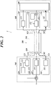
FIG. 2 is a block diagram of a power over fiber system according to a second embodiment of the present disclosure. -
FIG. 3 is a block diagram of the power over fiber system according to the second embodiment of the present disclosure and shows optical connectors and so forth. -
FIG. 4 is a block diagram of a power over fiber system according to another embodiment of the present disclosure. -
FIG. 5 is a block diagram of a shutter including an optical connector and a mating connector. -
FIG. 6 is a block diagram of the power over fiber system according to the second embodiment of the present disclosure with a control device added. - Hereinafter, embodiments of the present disclosure will be described with reference to the drawings.
- As shown in
FIG. 1 , a power over fiber (PoF) system 1A of this embodiment includes a power sourcing equipment (PSE) 110, anoptical fiber cable 200A and a powered device (PD) 310. - In the present disclosure, a power sourcing equipment converts electric power into optical energy and supplies (sources) the optical energy, and a powered device receives (draws) the supplied optical energy and converts the optical energy into electric power.
- The
power sourcing equipment 110 includes asemiconductor laser 111 for power supply. - The
optical fiber cable 200A includes anoptical fiber 250A that forms a transmission path of feed light. - The powered
device 310 includes aphotoelectric conversion element 311. - The
power sourcing equipment 110 is connected to a power source, and electrically drives thesemiconductor laser 111 and so forth. - The
semiconductor laser 111 oscillates with the electric power from the power source, thereby outputtingfeed light 112. - The
optical fiber cable 200A has oneend 201A connectable to thepower sourcing equipment 110 and theother end 202A connectable to the powereddevice 310 to transmit thefeed light 112. - The
feed light 112 from thepower sourcing equipment 110 is input to the oneend 201A of theoptical fiber cable 200A, propagates through theoptical fiber 250A, and is output from theother end 202A of theoptical fiber cable 200A to the powereddevice 310. - The
photoelectric conversion element 311 converts thefeed light 112 transmitted through theoptical fiber cable 200A into electric power. The electric power obtained by the conversion of thefeed light 112 by thephotoelectric conversion element 311 is driving power needed in the powereddevice 310. The powereddevice 310 is capable of outputting, for an external device(s), the electric power obtained by the conversion of thefeed light 112 by thephotoelectric conversion element 311. - Semiconductor materials of semiconductor regions of the
semiconductor laser 111 and thephotoelectric conversion element 311 are semiconductors having a laser wavelength being a short wavelength of 500 nm or less. The semiconductor regions exhibit light-electricity conversion effect. - Semiconductors having a laser wavelength being a short wavelength have a large band gap and a high photoelectric conversion efficiency, and hence improve photoelectric conversion efficiency at the power supplying side and the power receiving side in optical power supply, and improve optical power supply efficiency.
- Hence, as the semiconductor materials, laser media having a laser wavelength (base wave) of 200 nm to 500 nm may be used. Examples thereof include diamond, gallium oxide, aluminum nitride and gallium nitride.
- Further, as the semiconductor materials, semiconductors having a band gap of 2.4 eV or greater are used.
- For example, laser media having a band gap of 2.4 eV to 6.2 eV may be used. Examples thereof include diamond, gallium oxide, aluminum nitride and gallium nitride.
- Laser light having a longer wavelength tends to have a higher transmission efficiency, whereas laser light having a shorter wavelength tends to have a higher photoelectric conversion efficiency. Hence, when laser light is transmitted for a long distance, laser media having a laser wavelength (base wave) of greater than 500 nm may be used as the semiconductor materials, whereas when the photoelectric conversion efficiency is given priority, laser media having a laser wavelength (base wave) of less than 200 nm may be used as the semiconductor materials.
- Any of these semiconductor materials may be used in one of the
semiconductor laser 111 and thephotoelectric conversion element 311. This improves the photoelectric conversion efficiency at either the power supplying side or the power receiving side, and improves the optical power supply efficiency. - As shown in
FIG. 2 , a power over fiber (PoF)system 1 of this embodiment includes a power supply system through an optical fiber and an optical communication system therethrough, and includes: a firstdata communication device 100 including a power sourcing equipment (PSE) 110; anoptical fiber cable 200; and a seconddata communication device 300 including a powered device (PD) 310. - The
power sourcing equipment 110 includes asemiconductor laser 111 for power supply. The firstdata communication device 100 includes, in addition to thepower sourcing equipment 110, atransmitter 120 and areceiver 130 for data communication. The firstdata communication device 100 corresponds to a data terminal equipment (DTE), a repeater or the like. Thetransmitter 120 includes asemiconductor laser 121 for signals and amodulator 122. Thereceiver 130 includes aphotodiode 131 for signals. - The
optical fiber cable 200 includes anoptical fiber 250 including: a core 210 that forms a transmission path of signal light; and acladding 220 that is arranged so as to surround the core 210 and forms a transmission path of feed light. - The powered
device 310 includes aphotoelectric conversion element 311. The seconddata communication device 300 includes, in addition to the powereddevice 310, atransmitter 320, areceiver 330 and adata processing unit 340. The seconddata communication device 300 corresponds to a power end station or the like. Thetransmitter 320 includes asemiconductor laser 321 for signals and amodulator 322. Thereceiver 330 includes aphotodiode 331 for signals. Thedata processing unit 340 processes received signals. The seconddata communication device 300 is a node in a communication network. The seconddata communication device 300 may be a node that communicates with another node. - The first
data communication device 100 is connected to a power source, and electrically drives thesemiconductor laser 111, thesemiconductor laser 121, themodulator 122, thephotodiode 131 and so forth. The firstdata communication device 100 is a node in a communication network. The firstdata communication device 100 may be a node that communicates with another node. - The
semiconductor laser 111 oscillates with the electric power from the power source, thereby outputtingfeed light 112. - The
photoelectric conversion element 311 converts thefeed light 112 transmitted through theoptical fiber cable 200 into electric power. The electric power obtained by the conversion of thefeed light 112 by thephotoelectric conversion element 311 is driving power needed in the seconddata communication device 300, for example, driving power for thetransmitter 320, thereceiver 330 and thedata processing unit 340. The seconddata communication device 300 may be capable of outputting, for an external device(s), the electric power obtained by the conversion of thefeed light 112 by thephotoelectric conversion element 311. - The
modulator 122 of thetransmitter 120 modulateslaser light 123 output by thesemiconductor laser 121 to signal light 125 on the basis oftransmission data 124, and outputs thesignal light 125. - The
photodiode 331 of thereceiver 330 demodulates thesignal light 125 transmitted through theoptical fiber cable 200 to an electric signal, and outputs the electric signal to thedata processing unit 340. Thedata processing unit 340 transmits data of the electric signal to a node, and also receives data from the node and outputs the data to themodulator 322 astransmission data 324. - The
modulator 322 of thetransmitter 320 modulateslaser light 323 output by thesemiconductor laser 321 to signal light 325 on the basis of thetransmission data 324, and outputs thesignal light 325. - The
photodiode 131 of thereceiver 130 demodulates thesignal light 325 transmitted through theoptical fiber cable 200 to an electric signal, and outputs the electric signal. Data of the electric signal is transmitted to a node, whereas data from the node is thetransmission data 124. - The
feed light 112 and the signal light 125 from the firstdata communication device 100 are input to oneend 201 of theoptical fiber cable 200, propagate through thecladding 220 and the core 210, respectively, and are output from theother end 202 of theoptical fiber cable 200 to the seconddata communication device 300. - The signal light 325 from the second
data communication device 300 is input to theother end 202 of theoptical fiber cable 200, propagates through the core 210, and is output from the oneend 201 of theoptical fiber cable 200 to the firstdata communication device 100. - As shown in
FIG. 3 , the firstdata communication device 100 includes a light input/output part 140 and anoptical connector 141 attached to the light input/output part 140, and the seconddata communication device 300 includes a light input/output part 350 and anoptical connector 351 attached to the light input/output part 350. Anoptical connector 230 provided at the oneend 201 of theoptical fiber cable 200 is connected to theoptical connector 141, and anoptical connector 240 provided at theother end 202 of theoptical fiber cable 200 is connected to theoptical connector 351. The light input/output part 140 guides thefeed light 112 to thecladding 220, guides thesignal light 125 to the core 210, and guides thesignal light 325 to thereceiver 130. The light input/output part 350 guides thefeed light 112 to thepowered device 310, guides thesignal light 125 to thereceiver 330, and guides thesignal light 325 to the core 210. - As described above, the
optical fiber cable 200 has the oneend 201 connectable to the firstdata communication device 100 and theother end 202 connectable to the seconddata communication device 300 to transmit thefeed light 112. In this embodiment, theoptical fiber cable 200 transmits thesignal light - As the semiconductor materials of the semiconductor regions, which exhibit the light-electricity conversion effect, of the
semiconductor laser 111 and thephotoelectric conversion element 311, any of those described in the first embodiment can be used, thereby achieving a high optical power supply efficiency. - Like an
optical fiber cable 200B of a power overfiber system 1B shown inFIG. 4 , anoptical fiber 260 that transmits signal light and anoptical fiber 270 that transmits feed light may be provided separately. Further, theoptical fiber cable 200B may be composed of a plurality of optical fiber cables. - Next, an optical connector including a shutter will be described with reference to
FIG. 5 . - As shown in
FIG. 5 , anoptical connector 410 is disposed at anoutput end 401 for thefeed light 112 in the power overfiber system - An
optical connector 420 is a mating connector that is connected to theoptical connector 410. - The
optical connector 410 is used as theoptical connector 141 or theoptical connector 240 shown inFIG. 3 , and theoptical connector 420 is used as theoptical connector 230 or theoptical connector 351 shown inFIG. 3 . - The
optical connector 410 has ashutter 411. - The
shutter 411 opens in conjunction with a connection operation of connecting theoptical connector 410 and theoptical connector 420 to one another to enable the connection. - The
shutter 411 closes in conjunction with a disconnection operation of disconnecting theoptical connector 410 and theoptical connector 420 from one another to block the feed light 112 from exiting to the outside. The mechanism that closes theshutter 411 is configured by a hinge mechanism or the like having an elastic member that biases theshutter 411 in a closing direction. - As one form thereof, as shown in
FIG. 5 , a form is carried out in which alight receiving surface 412 of theshutter 411, thelight receiving surface 412 receiving thefeed light 112 when theshutter 411 is closed, is a mirror plane. That is, thelight receiving surface 412 that is the inner surface of theshutter 411 is a mirror plane. Amember 413 that constitutes thelight receiving surface 412 is a reflecting mirror, and this mirror plane constitutes thelight receiving surface 412. - When the
shutter 411 is closed, thefeed light 112 is reflected by the mirror plane (412) of the reflecting mirror (413) and thereby becomes return light 402. Part of thereturn light 402 enters theoutput end 401. - A
control device 150 shown inFIG. 6 detects connector disengagement by detecting thereturn light 402 emitted from theshutter 411, and controls thepower sourcing equipment 110 such that thepower sourcing equipment 110 stops outputting thefeed light 112. - The
return light 402 comes back through the propagation path of the feed light or the propagation path of the signal light. Hence, thecontrol device 150 can detect the connector disengagement by analyzing thereturn light 402 received by a photodiode. As the photodiode, thephotodiode 131 may be used, or a dedicated one may be provided. - Instead of the reflecting mirror, a wavelength conversion material, such as a fluorescent material, may be used. That is, as shown in
FIG. 5 , a form is carried out in which thelight receiving surface 412 of theshutter 411, thelight receiving surface 412 receiving thefeed light 112 when theshutter 411 is closed, is made of a wavelength conversion material. In other words, themember 413 that constitutes thelight receiving surface 412 that is the inner surface of theshutter 411 is a wavelength conversion material. - When the
shutter 411 is closed, thefeed light 112 irradiates the wavelength conversion material (413), and thereturn light 402 containing light having a wavelength different from that of thefeed light 112 is emitted from the wavelength conversion material (413). Part of thereturn light 402 enters theoutput end 401. - The
control device 150 shown inFIG. 6 detects the connector disengagement by detecting the abovementioned component having a different wavelength contained in thereturn light 402 emitted from theshutter 411, and controls thepower sourcing equipment 110 such that thepower sourcing equipment 110 stops outputting thefeed light 112. - Selecting a wavelength conversion material that makes the
return light 402 contain a light having a wavelength different from either that of thefeed light 112 or that of the signal light can make discrimination of thereturn light 402 excellent. - The wavelength conversion material may be of a nature that converts the entire received light into light having a different wavelength(s), or of a nature that performs spread spectrum over the wavelength of the received light and a wavelength(s) different from that of the received light.
- As described above, the
shutter 411 can prevent leakage of thefeed light 112 at the time of the connector disengagement. - Further, the
return light 402 emitted from theshutter 411 makes it easy to detect the shutter disengagement. - The
light receiving surface 412 of theshutter 411 for thefeed light 112 being a mirror plane can ensure the intensity of thereturn light 402, and enables the detection even if the return path is a long distance. - The
light receiving surface 412 of theshutter 411 for thefeed light 112 being made of a wavelength conversion material can make discrimination of the return light 402 from other light, such as stray light internally derived, excellent, and ensure the detection accuracy of the connector disengagement. - Further, the
control device 150 stops the feed light 112 from being output, which can prevent heat generation or breakage caused by thefeed light 112 irradiating theshutter 411 for a long time and consequently prevent accidents, and also can stop wasteful electric power consumption. - Although some embodiments of the present disclosure have been described above, these embodiments are made for purposes of illustration and example only. The present invention can be carried out in various other forms, and each component may be omitted, replaced or modified/changed within a range not departing from the scope of the present invention , as defined in the appended claims
- The present invention is applicable to an optical connector and a power sourcing equipment of a power over fiber system and to a power over fiber system.
-
- 1A
- Power over Fiber System
- 1
- Power over Fiber System
- 1B
- Power over Fiber System
- 100
- First Data Communication Device
- 110
- Power Sourcing Equipment
- 111
- Semiconductor Laser for Power Supply
- 112
- Feed Light
- 120
- Transmitter
- 125
- Signal Light
- 130
- Receiver
- 140
- Light Input/Output Part
- 141
- Optical Connector
- 200A
- Optical Fiber Cable
- 200
- Optical Fiber Cable
- 200B
- Optical Fiber Cable
- 210
- Core
- 220
- Cladding
- 250A
- Optical Fiber
- 250
- Optical Fiber
- 260
- Optical Fiber
- 270
- Optical Fiber
- 300
- Second Data Communication Device
- 310
- Powered Device
- 311
- Photoelectric Conversion Element
- 320
- Transmitter
- 325
- Signal Light
- 330
- Receiver
- 350
- Light Input/Output Part
- 351
- Optical Connector
- 410
- Optical Connector
- 411
- Shutter
- 420
- Optical Connector
Claims (6)
- A power sourcing equipment (110) of a power over fiber system (1), comprising:an optical connector (410) comprising a shutter (411) configured to open in conjunction with a connection operation to enable the connection and to close in conjunction with a disconnection operation to block feed light (112) from exiting, whereina light receiving surface (412) of the shutter (411), the light receiving surface (412) configured to receive the feed light (112) when the shutter (411) is closed, is made of a wavelength conversion material or is a mirror plane, andthe optical connector (410) is disposed at a feed-light output end; anda semiconductor laser (111) that is configured to oscillate with electric power, thereby outputting the feed light (112), wherein a semiconductor material of a semiconductor region of the semiconductor laser (111), the semiconductor region exhibiting a light-electricity conversion effect, is a laser medium having a laser wavelength of 500 nm or less.
- The power sourcing equipment (110) according to claim 1, comprising
a control device (150) that is configured to detect connector disengagement by detecting return light (402) emitted from the shutter (411) and to stop the feed light (112) from being output. - A power over fiber system (1) comprising:the power sourcing equipment (110) according to claim 1, wherein the light receiving surface (412) of the shutter (411) is made of a wavelength conversion material;a powered device (310) including a photoelectric conversion element (311) that is configured to convert the feed light (112) output by the power sourcing equipment (110) into electric power;an optical fiber cable (200) having an end (201) connectable to the power sourcing equipment (110) and another end (202) connectable to the powered device (310) configured to transmit the feed light (112); anda further optical connector (410) including a shutter (411) that is configured to open in conjunction with a connection operation to enable the connection and to close in conjunction with a disconnection operation to block feed light (112) from exiting, whereina light receiving surface (412) of the shutter (411), the light receiving surface (412) receiving the feed light (112) when the shutter (411) is closed, is made of a wavelength conversion material or is a mirror plane, andthe further optical connector (410) is disposed at the another end (202) of the optical fiber cable (200).
- A power over fiber system (1) comprising:the power sourcing equipment (110) according to claim 1;a powered device (310) including a photoelectric conversion element (311) that is configured to convert the feed light (112) output by the power sourcing equipment (110) into electric power;an optical fiber cable (200) having an end (201) connectable to the power sourcing equipment (110) and another end (202) connectable to the powered device (310) configured to transmit the feed light (112); anda further optical connector (410) including a shutter (411) that is configured to open in conjunction with a connection operation to enable the connection and to close in conjunction with a disconnection operation to block feed light (112) from exiting, whereina light receiving surface (412) of the shutter (411), the light receiving surface (412) receiving the feed light (112) when the shutter (411) is closed, is made of a wavelength conversion material, andthe further optical connector (410) is disposed at the another end (202) of the optical fiber cable (200).
- The power over fiber system (1) according to claim 3 or 4, comprising a control device (150) that is configured to detect connector disengagement by detecting return light (402) emitted from the shutter (411) and to stop the feed light (112) from being output.
- A power over fiber system (1) comprising:the power sourcing equipment (110) according to claim 1, wherein the light receiving surface (412) of the shutter (411) is a mirror plane;a powered device (310) including a photoelectric conversion element (311) that is configured to convert the feed light (112) output by the power sourcing equipment (110) into electric power;an optical fiber cable (200) having an end (201) connectable to the power sourcing equipment (110) and another end (202) connectable to the powered device (310) configured to transmit the feed light (112);a further optical connector (410) including a shutter (411) that is configured to open in conjunction with a connection operation to enable the connection and to close in conjunction with a disconnection operation to block feed light (112) from exiting, whereina light receiving surface (412) of the shutter (411), the light receiving surface (412) being configured to receive the feed light (112) when the shutter (411) is closed, is a mirror plane, andthe further optical connector (410) is disposed at the another end (202) of the optical fiber cable (200); anda control device (150) that is configured to detect connector disengagement by detecting return light (402) emitted from the shutter (411) and to stop the feed light (112) from being output.
Applications Claiming Priority (2)
| Application Number | Priority Date | Filing Date | Title |
|---|---|---|---|
| JP2019105973A JP6890631B2 (en) | 2019-06-06 | 2019-06-06 | Optical connector and power supply device of optical fiber power supply system and optical fiber power supply system |
| PCT/JP2020/021305 WO2020246375A1 (en) | 2019-06-06 | 2020-05-29 | Optical connector for optical fiber power feed system, power feed device, and optical fiber power feed system |
Publications (3)
| Publication Number | Publication Date |
|---|---|
| EP3930216A1 EP3930216A1 (en) | 2021-12-29 |
| EP3930216A4 EP3930216A4 (en) | 2022-05-04 |
| EP3930216B1 true EP3930216B1 (en) | 2023-01-04 |
Family
ID=73652838
Family Applications (1)
| Application Number | Title | Priority Date | Filing Date |
|---|---|---|---|
| EP20818694.0A Active EP3930216B1 (en) | 2019-06-06 | 2020-05-29 | Optical connector for optical fiber power feed system, power feed device, and optical fiber power feed system |
Country Status (5)
| Country | Link |
|---|---|
| US (1) | US11509401B2 (en) |
| EP (1) | EP3930216B1 (en) |
| JP (1) | JP6890631B2 (en) |
| CN (1) | CN113544928A (en) |
| WO (1) | WO2020246375A1 (en) |
Families Citing this family (8)
| Publication number | Priority date | Publication date | Assignee | Title |
|---|---|---|---|---|
| US11575055B2 (en) | 2019-07-15 | 2023-02-07 | SLT Technologies, Inc | Methods for coupling of optical fibers to a power photodiode |
| US12250027B2 (en) | 2020-06-01 | 2025-03-11 | Nubis Communications, Inc. | Polarization-diversity optical power supply |
| US11621795B2 (en) | 2020-06-01 | 2023-04-04 | Nubis Communications, Inc. | Polarization-diversity optical power supply |
| US12615091B2 (en) | 2020-06-01 | 2026-04-28 | Ciena Corporation | Polarization-diversity optical power supply |
| CN117043022A (en) * | 2020-09-18 | 2023-11-10 | 努比斯通信公司 | Data processing system including optical communication module |
| WO2022169970A1 (en) * | 2021-02-03 | 2022-08-11 | Nubis Communications, Inc. | Communication systems having optical power supplies |
| US12066653B2 (en) | 2021-04-22 | 2024-08-20 | Nubis Communications, Inc. | Communication systems having optical power supplies |
| US20240255708A1 (en) * | 2023-01-30 | 2024-08-01 | Nokia Solutions And Networks Oy | Self-reporting optical connector device |
Family Cites Families (21)
| Publication number | Priority date | Publication date | Assignee | Title |
|---|---|---|---|---|
| JP2767984B2 (en) * | 1990-06-22 | 1998-06-25 | 日立電線株式会社 | Optical connector |
| JPH08331061A (en) | 1995-05-31 | 1996-12-13 | Fuji Electric Co Ltd | Optical signal transmission device |
| JP3644884B2 (en) | 1999-10-25 | 2005-05-11 | 古河電気工業株式会社 | Adapter with light shielding shutter and optical module receptacle with light shielding shutter |
| US6811325B2 (en) * | 2001-04-18 | 2004-11-02 | Corona Optical Systems, Inc. | Communications assembly disabling mechanism |
| JP2003131071A (en) * | 2001-10-30 | 2003-05-08 | Matsushita Electric Ind Co Ltd | Optical connector cap |
| JP2007094151A (en) | 2005-09-29 | 2007-04-12 | Chugoku Electric Power Co Inc:The | Signal processor and signal processing system |
| US8526810B2 (en) * | 2007-04-30 | 2013-09-03 | Finisar Corporation | Eye safety and interoperability of active cable devices |
| JP2010135989A (en) | 2008-12-03 | 2010-06-17 | Mitsubishi Electric Corp | Optic fiber, optical communication device, and optical communication method |
| WO2010146659A1 (en) | 2009-06-16 | 2010-12-23 | 富士通オプティカルコンポーネンツ株式会社 | Optical transmission apparatus |
| US20110278479A1 (en) * | 2010-05-11 | 2011-11-17 | Searete Llc, A Limited Liability Corporation Of The State Of Delaware | Optical power transmission system and method having counter-propagating control signal |
| CN201878048U (en) | 2010-11-04 | 2011-06-22 | 中电普瑞科技有限公司 | Device for transmitting energy by multimode communication optical fiber |
| CN202083537U (en) * | 2011-05-05 | 2011-12-21 | 禾普股份有限公司 | Optical fiber detection device |
| WO2015133164A1 (en) * | 2014-03-06 | 2015-09-11 | ソニー株式会社 | Optical connector, cable, and optical communication device |
| WO2015158564A1 (en) * | 2014-04-16 | 2015-10-22 | Koninklijke Philips N.V. | Optical fiber calibration connector |
| JP6187691B2 (en) * | 2014-06-12 | 2017-08-30 | 株式会社島津製作所 | Fiber coupling module |
| CN104459670B (en) * | 2014-12-04 | 2017-08-11 | 北京理工大学 | A kind of multispectral sensing Wavelength conversion system based on fiber array |
| CN105785261A (en) * | 2014-12-23 | 2016-07-20 | 南京南瑞继保电气有限公司 | High-speed switch detection device and method |
| US9673893B2 (en) * | 2015-03-20 | 2017-06-06 | Oracle International Corporation | Safety-enhanced laser array |
| JP6283006B2 (en) * | 2015-09-18 | 2018-02-21 | 株式会社フジクラ | Optical connector parts |
| CN113382523B (en) * | 2017-06-02 | 2023-04-18 | 深圳市绎立锐光科技开发有限公司 | Laser optical fiber lighting system, indoor lighting system and outdoor lighting system |
| US10313026B2 (en) * | 2017-06-27 | 2019-06-04 | Rolls-Royce North American Technologies, Inc. | Power and communications over fiber optic cabling |
-
2019
- 2019-06-06 JP JP2019105973A patent/JP6890631B2/en active Active
-
2020
- 2020-05-29 CN CN202080019128.6A patent/CN113544928A/en active Pending
- 2020-05-29 WO PCT/JP2020/021305 patent/WO2020246375A1/en not_active Ceased
- 2020-05-29 US US17/442,619 patent/US11509401B2/en active Active
- 2020-05-29 EP EP20818694.0A patent/EP3930216B1/en active Active
Also Published As
| Publication number | Publication date |
|---|---|
| JP6890631B2 (en) | 2021-06-18 |
| WO2020246375A1 (en) | 2020-12-10 |
| CN113544928A (en) | 2021-10-22 |
| US20220094449A1 (en) | 2022-03-24 |
| EP3930216A4 (en) | 2022-05-04 |
| EP3930216A1 (en) | 2021-12-29 |
| JP2020202423A (en) | 2020-12-17 |
| US11509401B2 (en) | 2022-11-22 |
Similar Documents
| Publication | Publication Date | Title |
|---|---|---|
| US11509401B2 (en) | Optical connector and power sourcing equipment of power over fiber system, and power over fiber system | |
| EP4033678B1 (en) | Optical power supply system | |
| EP3829085B1 (en) | Optical fiber power supply system and data communication device | |
| EP3930146B1 (en) | Optical fiber power supply system and optical fiber cable | |
| EP4050818B1 (en) | Optical fiber power supply system | |
| US11757536B2 (en) | Power over fiber system | |
| EP4047838A1 (en) | Optical fiber power feeding system | |
| JP7598985B2 (en) | Photoelectric Adapter | |
| US11888329B2 (en) | Power over fiber system and feed light visualization lid member | |
| US20220224421A1 (en) | Powered device and power over fiber system | |
| EP3926858B1 (en) | Optical fiber power feeding system | |
| US11888534B2 (en) | Power sourcing equipment of power-over-fiber system and power-over-fiber system | |
| US20230111478A1 (en) | Optical fiber cable for feed-light transmission and power-over-fiber system |
Legal Events
| Date | Code | Title | Description |
|---|---|---|---|
| STAA | Information on the status of an ep patent application or granted ep patent |
Free format text: STATUS: THE INTERNATIONAL PUBLICATION HAS BEEN MADE |
|
| PUAI | Public reference made under article 153(3) epc to a published international application that has entered the european phase |
Free format text: ORIGINAL CODE: 0009012 |
|
| STAA | Information on the status of an ep patent application or granted ep patent |
Free format text: STATUS: REQUEST FOR EXAMINATION WAS MADE |
|
| 17P | Request for examination filed |
Effective date: 20210923 |
|
| AK | Designated contracting states |
Kind code of ref document: A1 Designated state(s): AL AT BE BG CH CY CZ DE DK EE ES FI FR GB GR HR HU IE IS IT LI LT LU LV MC MK MT NL NO PL PT RO RS SE SI SK SM TR |
|
| REG | Reference to a national code |
Ref country code: DE Ref legal event code: R079 Ref document number: 602020007410 Country of ref document: DE Free format text: PREVIOUS MAIN CLASS: H04B0010071000 Ipc: H04B0010800000 |
|
| A4 | Supplementary search report drawn up and despatched |
Effective date: 20220404 |
|
| RIC1 | Information provided on ipc code assigned before grant |
Ipc: G02B 6/42 20060101ALI20220329BHEP Ipc: H04B 10/80 20130101AFI20220329BHEP |
|
| DAV | Request for validation of the european patent (deleted) | ||
| DAX | Request for extension of the european patent (deleted) | ||
| GRAP | Despatch of communication of intention to grant a patent |
Free format text: ORIGINAL CODE: EPIDOSNIGR1 |
|
| STAA | Information on the status of an ep patent application or granted ep patent |
Free format text: STATUS: GRANT OF PATENT IS INTENDED |
|
| INTG | Intention to grant announced |
Effective date: 20221005 |
|
| GRAS | Grant fee paid |
Free format text: ORIGINAL CODE: EPIDOSNIGR3 |
|
| GRAA | (expected) grant |
Free format text: ORIGINAL CODE: 0009210 |
|
| STAA | Information on the status of an ep patent application or granted ep patent |
Free format text: STATUS: THE PATENT HAS BEEN GRANTED |
|
| AK | Designated contracting states |
Kind code of ref document: B1 Designated state(s): AL AT BE BG CH CY CZ DE DK EE ES FI FR GB GR HR HU IE IS IT LI LT LU LV MC MK MT NL NO PL PT RO RS SE SI SK SM TR |
|
| REG | Reference to a national code |
Ref country code: GB Ref legal event code: FG4D |
|
| REG | Reference to a national code |
Ref country code: CH Ref legal event code: EP |
|
| REG | Reference to a national code |
Ref country code: AT Ref legal event code: REF Ref document number: 1542674 Country of ref document: AT Kind code of ref document: T Effective date: 20230115 |
|
| REG | Reference to a national code |
Ref country code: DE Ref legal event code: R096 Ref document number: 602020007410 Country of ref document: DE |
|
| REG | Reference to a national code |
Ref country code: IE Ref legal event code: FG4D |
|
| REG | Reference to a national code |
Ref country code: LT Ref legal event code: MG9D |
|
| REG | Reference to a national code |
Ref country code: NL Ref legal event code: MP Effective date: 20230104 |
|
| P01 | Opt-out of the competence of the unified patent court (upc) registered |
Effective date: 20230505 |
|
| REG | Reference to a national code |
Ref country code: AT Ref legal event code: MK05 Ref document number: 1542674 Country of ref document: AT Kind code of ref document: T Effective date: 20230104 |
|
| PG25 | Lapsed in a contracting state [announced via postgrant information from national office to epo] |
Ref country code: NL Free format text: LAPSE BECAUSE OF FAILURE TO SUBMIT A TRANSLATION OF THE DESCRIPTION OR TO PAY THE FEE WITHIN THE PRESCRIBED TIME-LIMIT Effective date: 20230104 |
|
| PG25 | Lapsed in a contracting state [announced via postgrant information from national office to epo] |
Ref country code: RS Free format text: LAPSE BECAUSE OF FAILURE TO SUBMIT A TRANSLATION OF THE DESCRIPTION OR TO PAY THE FEE WITHIN THE PRESCRIBED TIME-LIMIT Effective date: 20230104 Ref country code: PT Free format text: LAPSE BECAUSE OF FAILURE TO SUBMIT A TRANSLATION OF THE DESCRIPTION OR TO PAY THE FEE WITHIN THE PRESCRIBED TIME-LIMIT Effective date: 20230504 Ref country code: NO Free format text: LAPSE BECAUSE OF FAILURE TO SUBMIT A TRANSLATION OF THE DESCRIPTION OR TO PAY THE FEE WITHIN THE PRESCRIBED TIME-LIMIT Effective date: 20230404 Ref country code: LV Free format text: LAPSE BECAUSE OF FAILURE TO SUBMIT A TRANSLATION OF THE DESCRIPTION OR TO PAY THE FEE WITHIN THE PRESCRIBED TIME-LIMIT Effective date: 20230104 Ref country code: LT Free format text: LAPSE BECAUSE OF FAILURE TO SUBMIT A TRANSLATION OF THE DESCRIPTION OR TO PAY THE FEE WITHIN THE PRESCRIBED TIME-LIMIT Effective date: 20230104 Ref country code: HR Free format text: LAPSE BECAUSE OF FAILURE TO SUBMIT A TRANSLATION OF THE DESCRIPTION OR TO PAY THE FEE WITHIN THE PRESCRIBED TIME-LIMIT Effective date: 20230104 Ref country code: ES Free format text: LAPSE BECAUSE OF FAILURE TO SUBMIT A TRANSLATION OF THE DESCRIPTION OR TO PAY THE FEE WITHIN THE PRESCRIBED TIME-LIMIT Effective date: 20230104 Ref country code: AT Free format text: LAPSE BECAUSE OF FAILURE TO SUBMIT A TRANSLATION OF THE DESCRIPTION OR TO PAY THE FEE WITHIN THE PRESCRIBED TIME-LIMIT Effective date: 20230104 |
|
| PG25 | Lapsed in a contracting state [announced via postgrant information from national office to epo] |
Ref country code: SE Free format text: LAPSE BECAUSE OF FAILURE TO SUBMIT A TRANSLATION OF THE DESCRIPTION OR TO PAY THE FEE WITHIN THE PRESCRIBED TIME-LIMIT Effective date: 20230104 Ref country code: PL Free format text: LAPSE BECAUSE OF FAILURE TO SUBMIT A TRANSLATION OF THE DESCRIPTION OR TO PAY THE FEE WITHIN THE PRESCRIBED TIME-LIMIT Effective date: 20230104 Ref country code: IS Free format text: LAPSE BECAUSE OF FAILURE TO SUBMIT A TRANSLATION OF THE DESCRIPTION OR TO PAY THE FEE WITHIN THE PRESCRIBED TIME-LIMIT Effective date: 20230504 Ref country code: GR Free format text: LAPSE BECAUSE OF FAILURE TO SUBMIT A TRANSLATION OF THE DESCRIPTION OR TO PAY THE FEE WITHIN THE PRESCRIBED TIME-LIMIT Effective date: 20230405 Ref country code: FI Free format text: LAPSE BECAUSE OF FAILURE TO SUBMIT A TRANSLATION OF THE DESCRIPTION OR TO PAY THE FEE WITHIN THE PRESCRIBED TIME-LIMIT Effective date: 20230104 |
|
| REG | Reference to a national code |
Ref country code: DE Ref legal event code: R097 Ref document number: 602020007410 Country of ref document: DE |
|
| PG25 | Lapsed in a contracting state [announced via postgrant information from national office to epo] |
Ref country code: SM Free format text: LAPSE BECAUSE OF FAILURE TO SUBMIT A TRANSLATION OF THE DESCRIPTION OR TO PAY THE FEE WITHIN THE PRESCRIBED TIME-LIMIT Effective date: 20230104 Ref country code: RO Free format text: LAPSE BECAUSE OF FAILURE TO SUBMIT A TRANSLATION OF THE DESCRIPTION OR TO PAY THE FEE WITHIN THE PRESCRIBED TIME-LIMIT Effective date: 20230104 Ref country code: EE Free format text: LAPSE BECAUSE OF FAILURE TO SUBMIT A TRANSLATION OF THE DESCRIPTION OR TO PAY THE FEE WITHIN THE PRESCRIBED TIME-LIMIT Effective date: 20230104 Ref country code: DK Free format text: LAPSE BECAUSE OF FAILURE TO SUBMIT A TRANSLATION OF THE DESCRIPTION OR TO PAY THE FEE WITHIN THE PRESCRIBED TIME-LIMIT Effective date: 20230104 Ref country code: CZ Free format text: LAPSE BECAUSE OF FAILURE TO SUBMIT A TRANSLATION OF THE DESCRIPTION OR TO PAY THE FEE WITHIN THE PRESCRIBED TIME-LIMIT Effective date: 20230104 |
|
| PLBE | No opposition filed within time limit |
Free format text: ORIGINAL CODE: 0009261 |
|
| STAA | Information on the status of an ep patent application or granted ep patent |
Free format text: STATUS: NO OPPOSITION FILED WITHIN TIME LIMIT |
|
| PG25 | Lapsed in a contracting state [announced via postgrant information from national office to epo] |
Ref country code: SK Free format text: LAPSE BECAUSE OF FAILURE TO SUBMIT A TRANSLATION OF THE DESCRIPTION OR TO PAY THE FEE WITHIN THE PRESCRIBED TIME-LIMIT Effective date: 20230104 |
|
| 26N | No opposition filed |
Effective date: 20231005 |
|
| REG | Reference to a national code |
Ref country code: CH Ref legal event code: PL |
|
| PG25 | Lapsed in a contracting state [announced via postgrant information from national office to epo] |
Ref country code: MC Free format text: LAPSE BECAUSE OF FAILURE TO SUBMIT A TRANSLATION OF THE DESCRIPTION OR TO PAY THE FEE WITHIN THE PRESCRIBED TIME-LIMIT Effective date: 20230104 |
|
| REG | Reference to a national code |
Ref country code: BE Ref legal event code: MM Effective date: 20230531 |
|
| PG25 | Lapsed in a contracting state [announced via postgrant information from national office to epo] |
Ref country code: SI Free format text: LAPSE BECAUSE OF FAILURE TO SUBMIT A TRANSLATION OF THE DESCRIPTION OR TO PAY THE FEE WITHIN THE PRESCRIBED TIME-LIMIT Effective date: 20230104 Ref country code: MC Free format text: LAPSE BECAUSE OF FAILURE TO SUBMIT A TRANSLATION OF THE DESCRIPTION OR TO PAY THE FEE WITHIN THE PRESCRIBED TIME-LIMIT Effective date: 20230104 Ref country code: LU Free format text: LAPSE BECAUSE OF NON-PAYMENT OF DUE FEES Effective date: 20230529 Ref country code: CH Free format text: LAPSE BECAUSE OF NON-PAYMENT OF DUE FEES Effective date: 20230531 Ref country code: LI Free format text: LAPSE BECAUSE OF NON-PAYMENT OF DUE FEES Effective date: 20230531 |
|
| REG | Reference to a national code |
Ref country code: IE Ref legal event code: MM4A |
|
| PG25 | Lapsed in a contracting state [announced via postgrant information from national office to epo] |
Ref country code: IE Free format text: LAPSE BECAUSE OF NON-PAYMENT OF DUE FEES Effective date: 20230529 |
|
| PG25 | Lapsed in a contracting state [announced via postgrant information from national office to epo] |
Ref country code: IE Free format text: LAPSE BECAUSE OF NON-PAYMENT OF DUE FEES Effective date: 20230529 |
|
| PG25 | Lapsed in a contracting state [announced via postgrant information from national office to epo] |
Ref country code: IT Free format text: LAPSE BECAUSE OF FAILURE TO SUBMIT A TRANSLATION OF THE DESCRIPTION OR TO PAY THE FEE WITHIN THE PRESCRIBED TIME-LIMIT Effective date: 20230104 Ref country code: BE Free format text: LAPSE BECAUSE OF NON-PAYMENT OF DUE FEES Effective date: 20230531 |
|
| PG25 | Lapsed in a contracting state [announced via postgrant information from national office to epo] |
Ref country code: BG Free format text: LAPSE BECAUSE OF FAILURE TO SUBMIT A TRANSLATION OF THE DESCRIPTION OR TO PAY THE FEE WITHIN THE PRESCRIBED TIME-LIMIT Effective date: 20230104 |
|
| PG25 | Lapsed in a contracting state [announced via postgrant information from national office to epo] |
Ref country code: BG Free format text: LAPSE BECAUSE OF FAILURE TO SUBMIT A TRANSLATION OF THE DESCRIPTION OR TO PAY THE FEE WITHIN THE PRESCRIBED TIME-LIMIT Effective date: 20230104 |
|
| PGFP | Annual fee paid to national office [announced via postgrant information from national office to epo] |
Ref country code: DE Payment date: 20250402 Year of fee payment: 6 |
|
| PGFP | Annual fee paid to national office [announced via postgrant information from national office to epo] |
Ref country code: GB Payment date: 20250401 Year of fee payment: 6 |
|
| PGFP | Annual fee paid to national office [announced via postgrant information from national office to epo] |
Ref country code: FR Payment date: 20250401 Year of fee payment: 6 |
|
| PG25 | Lapsed in a contracting state [announced via postgrant information from national office to epo] |
Ref country code: CY Free format text: LAPSE BECAUSE OF FAILURE TO SUBMIT A TRANSLATION OF THE DESCRIPTION OR TO PAY THE FEE WITHIN THE PRESCRIBED TIME-LIMIT; INVALID AB INITIO Effective date: 20200529 |
|
| PG25 | Lapsed in a contracting state [announced via postgrant information from national office to epo] |
Ref country code: HU Free format text: LAPSE BECAUSE OF FAILURE TO SUBMIT A TRANSLATION OF THE DESCRIPTION OR TO PAY THE FEE WITHIN THE PRESCRIBED TIME-LIMIT; INVALID AB INITIO Effective date: 20200529 |
|
| PG25 | Lapsed in a contracting state [announced via postgrant information from national office to epo] |
Ref country code: TR Free format text: LAPSE BECAUSE OF FAILURE TO SUBMIT A TRANSLATION OF THE DESCRIPTION OR TO PAY THE FEE WITHIN THE PRESCRIBED TIME-LIMIT Effective date: 20230104 |