EP3930173A1 - Method for controlling an inverter - Google Patents
Method for controlling an inverter Download PDFInfo
- Publication number
- EP3930173A1 EP3930173A1 EP20182525.4A EP20182525A EP3930173A1 EP 3930173 A1 EP3930173 A1 EP 3930173A1 EP 20182525 A EP20182525 A EP 20182525A EP 3930173 A1 EP3930173 A1 EP 3930173A1
- Authority
- EP
- European Patent Office
- Prior art keywords
- converter
- current
- sub
- phase
- switch position
- Prior art date
- Legal status (The legal status is an assumption and is not a legal conclusion. Google has not performed a legal analysis and makes no representation as to the accuracy of the status listed.)
- Pending
Links
Images


Classifications
-
- H—ELECTRICITY
- H02—GENERATION; CONVERSION OR DISTRIBUTION OF ELECTRIC POWER
- H02M—APPARATUS FOR CONVERSION BETWEEN AC AND AC, BETWEEN AC AND DC, OR BETWEEN DC AND DC, AND FOR USE WITH MAINS OR SIMILAR POWER SUPPLY SYSTEMS; CONVERSION OF DC OR AC INPUT POWER INTO SURGE OUTPUT POWER; CONTROL OR REGULATION THEREOF
- H02M7/00—Conversion of ac power input into dc power output; Conversion of dc power input into ac power output
- H02M7/42—Conversion of dc power input into ac power output without possibility of reversal
- H02M7/44—Conversion of dc power input into ac power output without possibility of reversal by static converters
- H02M7/48—Conversion of dc power input into ac power output without possibility of reversal by static converters using discharge tubes with control electrode or semiconductor devices with control electrode
- H02M7/493—Conversion of dc power input into ac power output without possibility of reversal by static converters using discharge tubes with control electrode or semiconductor devices with control electrode the static converters being arranged for operation in parallel
-
- H—ELECTRICITY
- H02—GENERATION; CONVERSION OR DISTRIBUTION OF ELECTRIC POWER
- H02M—APPARATUS FOR CONVERSION BETWEEN AC AND AC, BETWEEN AC AND DC, OR BETWEEN DC AND DC, AND FOR USE WITH MAINS OR SIMILAR POWER SUPPLY SYSTEMS; CONVERSION OF DC OR AC INPUT POWER INTO SURGE OUTPUT POWER; CONTROL OR REGULATION THEREOF
- H02M7/00—Conversion of ac power input into dc power output; Conversion of dc power input into ac power output
- H02M7/42—Conversion of dc power input into ac power output without possibility of reversal
- H02M7/44—Conversion of dc power input into ac power output without possibility of reversal by static converters
- H02M7/48—Conversion of dc power input into ac power output without possibility of reversal by static converters using discharge tubes with control electrode or semiconductor devices with control electrode
- H02M7/53—Conversion of dc power input into ac power output without possibility of reversal by static converters using discharge tubes with control electrode or semiconductor devices with control electrode using devices of a triode or transistor type requiring continuous application of a control signal
- H02M7/537—Conversion of dc power input into ac power output without possibility of reversal by static converters using discharge tubes with control electrode or semiconductor devices with control electrode using devices of a triode or transistor type requiring continuous application of a control signal using semiconductor devices only, e.g. single switched pulse inverters
- H02M7/539—Conversion of dc power input into ac power output without possibility of reversal by static converters using discharge tubes with control electrode or semiconductor devices with control electrode using devices of a triode or transistor type requiring continuous application of a control signal using semiconductor devices only, e.g. single switched pulse inverters with automatic control of output wave form or frequency
- H02M7/5395—Conversion of dc power input into ac power output without possibility of reversal by static converters using discharge tubes with control electrode or semiconductor devices with control electrode using devices of a triode or transistor type requiring continuous application of a control signal using semiconductor devices only, e.g. single switched pulse inverters with automatic control of output wave form or frequency by pulse-width modulation
-
- F—MECHANICAL ENGINEERING; LIGHTING; HEATING; WEAPONS; BLASTING
- F03—MACHINES OR ENGINES FOR LIQUIDS; WIND, SPRING, OR WEIGHT MOTORS; PRODUCING MECHANICAL POWER OR A REACTIVE PROPULSIVE THRUST, NOT OTHERWISE PROVIDED FOR
- F03D—WIND MOTORS
- F03D9/00—Adaptations of wind motors for special use; Combinations of wind motors with apparatus driven thereby; Wind motors specially adapted for installation in particular locations
- F03D9/20—Wind motors characterised by the driven apparatus
- F03D9/25—Wind motors characterised by the driven apparatus the apparatus being an electrical generator
-
- H—ELECTRICITY
- H02—GENERATION; CONVERSION OR DISTRIBUTION OF ELECTRIC POWER
- H02J—CIRCUIT ARRANGEMENTS OR SYSTEMS FOR SUPPLYING OR DISTRIBUTING ELECTRIC POWER; SYSTEMS FOR STORING ELECTRIC ENERGY
- H02J3/00—Circuit arrangements for ac mains or ac distribution networks
- H02J3/38—Arrangements for parallely feeding a single network by two or more generators, converters or transformers
- H02J3/381—Dispersed generators
-
- H—ELECTRICITY
- H02—GENERATION; CONVERSION OR DISTRIBUTION OF ELECTRIC POWER
- H02M—APPARATUS FOR CONVERSION BETWEEN AC AND AC, BETWEEN AC AND DC, OR BETWEEN DC AND DC, AND FOR USE WITH MAINS OR SIMILAR POWER SUPPLY SYSTEMS; CONVERSION OF DC OR AC INPUT POWER INTO SURGE OUTPUT POWER; CONTROL OR REGULATION THEREOF
- H02M1/00—Details of apparatus for conversion
- H02M1/0003—Details of control, feedback or regulation circuits
- H02M1/0009—Devices or circuits for detecting current in a converter
-
- H—ELECTRICITY
- H02—GENERATION; CONVERSION OR DISTRIBUTION OF ELECTRIC POWER
- H02M—APPARATUS FOR CONVERSION BETWEEN AC AND AC, BETWEEN AC AND DC, OR BETWEEN DC AND DC, AND FOR USE WITH MAINS OR SIMILAR POWER SUPPLY SYSTEMS; CONVERSION OF DC OR AC INPUT POWER INTO SURGE OUTPUT POWER; CONTROL OR REGULATION THEREOF
- H02M7/00—Conversion of ac power input into dc power output; Conversion of dc power input into ac power output
- H02M7/42—Conversion of dc power input into ac power output without possibility of reversal
- H02M7/44—Conversion of dc power input into ac power output without possibility of reversal by static converters
- H02M7/48—Conversion of dc power input into ac power output without possibility of reversal by static converters using discharge tubes with control electrode or semiconductor devices with control electrode
- H02M7/53—Conversion of dc power input into ac power output without possibility of reversal by static converters using discharge tubes with control electrode or semiconductor devices with control electrode using devices of a triode or transistor type requiring continuous application of a control signal
- H02M7/537—Conversion of dc power input into ac power output without possibility of reversal by static converters using discharge tubes with control electrode or semiconductor devices with control electrode using devices of a triode or transistor type requiring continuous application of a control signal using semiconductor devices only, e.g. single switched pulse inverters
- H02M7/5387—Conversion of dc power input into ac power output without possibility of reversal by static converters using discharge tubes with control electrode or semiconductor devices with control electrode using devices of a triode or transistor type requiring continuous application of a control signal using semiconductor devices only, e.g. single switched pulse inverters in a bridge configuration
- H02M7/53871—Conversion of dc power input into ac power output without possibility of reversal by static converters using discharge tubes with control electrode or semiconductor devices with control electrode using devices of a triode or transistor type requiring continuous application of a control signal using semiconductor devices only, e.g. single switched pulse inverters in a bridge configuration with automatic control of output voltage or current
- H02M7/53873—Conversion of dc power input into ac power output without possibility of reversal by static converters using discharge tubes with control electrode or semiconductor devices with control electrode using devices of a triode or transistor type requiring continuous application of a control signal using semiconductor devices only, e.g. single switched pulse inverters in a bridge configuration with automatic control of output voltage or current with digital control
-
- F—MECHANICAL ENGINEERING; LIGHTING; HEATING; WEAPONS; BLASTING
- F05—INDEXING SCHEMES RELATING TO ENGINES OR PUMPS IN VARIOUS SUBCLASSES OF CLASSES F01-F04
- F05B—INDEXING SCHEME RELATING TO WIND, SPRING, WEIGHT, INERTIA OR LIKE MOTORS, TO MACHINES OR ENGINES FOR LIQUIDS COVERED BY SUBCLASSES F03B, F03D AND F03G
- F05B2220/00—Application
- F05B2220/70—Application in combination with
- F05B2220/706—Application in combination with an electrical generator
-
- H—ELECTRICITY
- H02—GENERATION; CONVERSION OR DISTRIBUTION OF ELECTRIC POWER
- H02J—CIRCUIT ARRANGEMENTS OR SYSTEMS FOR SUPPLYING OR DISTRIBUTING ELECTRIC POWER; SYSTEMS FOR STORING ELECTRIC ENERGY
- H02J2300/00—Systems for supplying or distributing electric power characterised by decentralized, dispersed, or local generation
- H02J2300/20—The dispersed energy generation being of renewable origin
- H02J2300/28—The renewable source being wind energy
-
- H—ELECTRICITY
- H02—GENERATION; CONVERSION OR DISTRIBUTION OF ELECTRIC POWER
- H02M—APPARATUS FOR CONVERSION BETWEEN AC AND AC, BETWEEN AC AND DC, OR BETWEEN DC AND DC, AND FOR USE WITH MAINS OR SIMILAR POWER SUPPLY SYSTEMS; CONVERSION OF DC OR AC INPUT POWER INTO SURGE OUTPUT POWER; CONTROL OR REGULATION THEREOF
- H02M1/00—Details of apparatus for conversion
- H02M1/32—Means for protecting converters other than automatic disconnection
- H02M1/325—Means for protecting converters other than automatic disconnection with means for allowing continuous operation despite a fault, i.e. fault tolerant converters
-
- H—ELECTRICITY
- H02—GENERATION; CONVERSION OR DISTRIBUTION OF ELECTRIC POWER
- H02M—APPARATUS FOR CONVERSION BETWEEN AC AND AC, BETWEEN AC AND DC, OR BETWEEN DC AND DC, AND FOR USE WITH MAINS OR SIMILAR POWER SUPPLY SYSTEMS; CONVERSION OF DC OR AC INPUT POWER INTO SURGE OUTPUT POWER; CONTROL OR REGULATION THEREOF
- H02M5/00—Conversion of ac power input into ac power output, e.g. for change of voltage, for change of frequency, for change of number of phases
- H02M5/40—Conversion of ac power input into ac power output, e.g. for change of voltage, for change of frequency, for change of number of phases with intermediate conversion into dc
- H02M5/42—Conversion of ac power input into ac power output, e.g. for change of voltage, for change of frequency, for change of number of phases with intermediate conversion into dc by static converters
- H02M5/44—Conversion of ac power input into ac power output, e.g. for change of voltage, for change of frequency, for change of number of phases with intermediate conversion into dc by static converters using discharge tubes or semiconductor devices to convert the intermediate dc into ac
- H02M5/453—Conversion of ac power input into ac power output, e.g. for change of voltage, for change of frequency, for change of number of phases with intermediate conversion into dc by static converters using discharge tubes or semiconductor devices to convert the intermediate dc into ac using devices of a triode or transistor type requiring continuous application of a control signal
- H02M5/458—Conversion of ac power input into ac power output, e.g. for change of voltage, for change of frequency, for change of number of phases with intermediate conversion into dc by static converters using discharge tubes or semiconductor devices to convert the intermediate dc into ac using devices of a triode or transistor type requiring continuous application of a control signal using semiconductor devices only
- H02M5/4585—Conversion of ac power input into ac power output, e.g. for change of voltage, for change of frequency, for change of number of phases with intermediate conversion into dc by static converters using discharge tubes or semiconductor devices to convert the intermediate dc into ac using devices of a triode or transistor type requiring continuous application of a control signal using semiconductor devices only having a rectifier with controlled elements
-
- Y—GENERAL TAGGING OF NEW TECHNOLOGICAL DEVELOPMENTS; GENERAL TAGGING OF CROSS-SECTIONAL TECHNOLOGIES SPANNING OVER SEVERAL SECTIONS OF THE IPC; TECHNICAL SUBJECTS COVERED BY FORMER USPC CROSS-REFERENCE ART COLLECTIONS [XRACs] AND DIGESTS
- Y02—TECHNOLOGIES OR APPLICATIONS FOR MITIGATION OR ADAPTATION AGAINST CLIMATE CHANGE
- Y02E—REDUCTION OF GREENHOUSE GAS [GHG] EMISSIONS, RELATED TO ENERGY GENERATION, TRANSMISSION OR DISTRIBUTION
- Y02E10/00—Energy generation through renewable energy sources
- Y02E10/70—Wind energy
- Y02E10/72—Wind turbines with rotation axis in wind direction
-
- Y—GENERAL TAGGING OF NEW TECHNOLOGICAL DEVELOPMENTS; GENERAL TAGGING OF CROSS-SECTIONAL TECHNOLOGIES SPANNING OVER SEVERAL SECTIONS OF THE IPC; TECHNICAL SUBJECTS COVERED BY FORMER USPC CROSS-REFERENCE ART COLLECTIONS [XRACs] AND DIGESTS
- Y02—TECHNOLOGIES OR APPLICATIONS FOR MITIGATION OR ADAPTATION AGAINST CLIMATE CHANGE
- Y02E—REDUCTION OF GREENHOUSE GAS [GHG] EMISSIONS, RELATED TO ENERGY GENERATION, TRANSMISSION OR DISTRIBUTION
- Y02E10/00—Energy generation through renewable energy sources
- Y02E10/70—Wind energy
- Y02E10/76—Power conversion electric or electronic aspects
Definitions
- the present invention relates to a method for controlling a converter having a plurality of, preferably parallel, converter modules, in particular a power converter of a wind power plant, and a generator of electrical energy having such a converter, in particular a wind power plant having such a converter.
- the object of the present invention is therefore to provide a method for controlling converter systems which have a multiplicity of parallel converter modules to be controlled in a coordinated manner.
- a method for controlling a converter having a plurality of, preferably parallel, converter modules, in particular a power converter of a wind turbine comprising the steps of: controlling a first converter module so that the converter module generates a first electrical alternating current in a first switch position; second converter module, so that the converter module generates a second electrical alternating current in a second switch position, superimposing the first electrical alternating current and the second electrical alternating current to form a total current, detecting the total current of the converter, determining a virtual current as a function of the first and second switch position, changing the first switch position of the first converter module and / or the second switch position of the second converter module depending on the total current and the virtual current.
- the converter is preferably designed as a converter system and comprises a plurality of converter modules that are connected to one another in parallel, in particular to add up the power output of the converter modules, so that the total output of the converter system is increased. Furthermore, the converter or the converter system is designed as an inverter of a power converter of a wind energy installation.
- the converter modules are preferably designed with 3 phases and each generate one current per phase.
- the converter is designed as a so-called power converter and / or as a grid converter.
- the converter comprises ten converter modules for this purpose, each with a nominal output of 400 kW, so that the converter has a total output of 4 MW.
- the converter also comprises a control unit which is set up to control the converter modules in such a way that the converter works both in terms of current and voltage on an electrical supply network.
- the first converter module is preferably connected in parallel to the second converter module in such a way that the first electrical alternating current and the second electrical alternating current superimpose to form a common converter current, the total current.
- the converter modules are controlled by a control unit in such a way that the converter modules each generate an alternating current by means of certain switch positions.
- These switch positions of a phase can also be summarized as the sum of all switch positions S ⁇ p or S ⁇ 123, with the switch positions of a converter module each being able to assume the discrete states 0 and 1, for example.
- the switch positions are preferably determined individually for each phase p and for each converter j.
- the currents generated by the converter modules are superimposed to form a total current ig.
- the converter has, for example, a node in which the currents generated by the converter modules are superimposed in phase, i.e. the current i 1,1 of the first phase of the first converter module with the current i 1,2 of the first phase of the second converter module, etc.
- this total current I gp of the converter is recorded, in particular on the network side, for example by a current recording that is connected to the control unit of the converter.
- the current is preferably detected in phases by the current detection at each output of each converter module in order to determine the total current i gp.
- a virtual current i v is determined as a function of the switch positions.
- all switch positions of all converter modules are added up.
- each switch has, for example, a discrete switch position +1 or -1, which is added to a sum.
- This sum is then used to determine a virtual current i v , for example by means of an integration, in particular by integrating the sum of all switch positions.
- the virtual current therefore particularly reflects a certain state of all switch positions of all converter modules of the converter.
- the virtual current also has the particular task of decoupling the switch positions from one another, preferably in phases, in particular in order to meet the converter and network requirements that are separate from one another.
- the virtual stream is therefore preferably used in particular to decouple the switches of one phase from the switches of another phase.
- the switch positions of the converter modules or the converter are then changed as a function of the total current recorded and the virtual current.
- a cascaded control is preferably used to change the first switch position and / or the second switch position, which has a superimposed and a subordinate control.
- the superimposed regulation is used in particular to determine the switch positions S ⁇ 123 of the converter.
- the choice of the values is, thanks to the decoupling by means of the virtual current i v separately for each phase, left to a tolerance band regulator or a control block, which is based on a previously made preselection, namely the values s ⁇ p + and s ⁇ p - selects the value that reduces the amount of control deviation.
- the preselection is designed in such a way that the amount of the derivative of the control error is as small as possible. This ensures the longest possible times between switching operations and thus reduces switching losses.
- the subordinate regulation is used in particular to distribute the sum switch positions made in the preselection to the converter modules and to set the individual currents of the converter.
- the subordinate regulation is preferably designed in such a way that the currents in the individual converter modules do not differ too greatly from one another or that a desired load distribution on the converter is ensured.
- each phase can be viewed separately from the others, which enables parallel processing.
- the switch positions of one and / or all of the converter modules are determined in parallel.
- the superimposed regulation and the subordinate regulation each comprise at least one hysteresis regulation or are designed as tolerance band regulators.
- the total current is preferably recorded by recording each current of each phase of each converter module.
- the total current is not recorded directly, but is recorded indirectly.
- the corresponding current of the converter module is recorded in each phase at the output of each converter module and then added up to form the total current.
- the current detection of each converter module is preferably used, which is preferably connected to the control of each converter module.
- the controls of the converter modules are also preferably connected to the control unit of the converter.
- the first switch position of the first converter module and / or the second switch position of the second converter module are preferably changed by means of control signals.
- the converter has, for example, a control unit that is connected to the controls of the converter modules.
- the control unit carries out the method described above or below and transmits the determined switch positions to the converter modules by means of control signals.
- the switch positions be explicitly transferred from the control unit of the converter to the controls of the converter modules.
- the controllers of the converter modules do not have to carry out any complex calculations.
- control signals include the explicit switch positions of the power electronic switches with a dead time.
- control signals include the switch positions of a half bridge (two power electronic switches) and the switch positions of the power electronic switches with a dead time is inserted by the controls of the converter modules.
- the first switch position of the first converter module and the second switch position of the second converter module are preferably changed as a function a sum of the switch positions of a phase across all converter modules, in particular using a tolerance band.
- the converter modules are controlled in phases by means of tolerance bands.
- L g describes the network inductance
- the voltage offset U res can also be referred to as a voltage error and is preferably used as a controller parameter in order to ensure controller safety.
- the voltage offset Ures greater than zero is preferably selected.
- a hysteresis is preferably implemented in such a way that the same switch position is used until
- > h ⁇ , for example by means of a time-discrete implementation according to s ⁇ p k ⁇ s ⁇ p - f u ⁇ re p k > H ⁇ s ⁇ p + f u ⁇ re p k > H ⁇ s ⁇ p - 1 otherwise .
- the virtual current i v is also used in particular to minimize the required intermediate circuit voltage in the converter or to optimize it downwards. This enables better utilization of the converter.
- the reference value for the total current of a phase i * gp is used as a setpoint value and is preferably set so that symmetrical mains currents arise.
- the first switch position of the first converter module and / or the second switch position of the second converter module are preferably changed as a function of a reference value for a current of one phase of a converter, in particular using a tolerance band.
- the superimposed regulation specifies how many switches are to be switched.
- the subordinate control then uses the reference values to select which switches are to be switched.
- a reference value for a current of one phase of a converter is 1kA and another reference value for another phase of a converter is 2kA.
- the converters would each generate 2kA.
- the subordinate control compares these values and in the latter case detects a smaller deviation and therefore switches this switch or switches this converter module (on).
- a generator of electrical energy comprising a converter having a plurality of, preferably parallel, converter modules, a control unit for controlling the converter modules of the converter, the control unit being set up to change the switch positions of the converter modules and a method as above or as described below.
- the generator of electrical energy is preferably a wind energy installation, in particular wherein the converter is designed as a power converter with at least 3 MW.
- the converter modules are designed essentially the same.
- Fig. 1 shows a perspective view of a wind energy installation 100.
- the wind energy installation 100 has a tower 102 and a nacelle 104.
- An aerodynamic rotor 106 with three rotor blades 108 and a spinner 110 is arranged on the nacelle 104.
- the rotor 106 is set in rotation by the wind during operation and thereby drives a generator in the nacelle.
- the generator generates a current to be fed in, which is fed into an electrical supply network by means of an inverter.
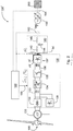
- Fig. 2 shows schematically and by way of example an electrical strand 100 ′ of a wind energy installation 100, as is preferred in FIG Figure 1 shown.
- the aerodynamic rotor of the wind energy installation 106 is connected to the generator 120 of the wind energy installation.
- the generator 120 is preferably designed as a six-phase ring generator.
- the generator 120 is also connected to an electrical supply network 200 or connected to the electrical supply network 200 via a converter 130 by means of a network protection device 140 and a transformer 150.
- the converter 130 has a rectifier 132 at the converter input.
- the rectifier 132 is also connected to a first DC voltage intermediate circuit 133.
- the first DC voltage intermediate circuit 133 is in turn connected to a step-up converter 134.
- the step-up converter 134 is in turn connected to a chopper 135.
- the chopper 135 is in turn connected to a second DC voltage intermediate circuit 136.
- the second DC voltage intermediate circuit 136 is in turn connected to an inverter 137.
- the inverter 137 itself forms the converter output, which is provided with a network protection device 140.
- the inverter 137 consists of a large number of inverter modules 137 ', as for example in FIG Fig. 3 and produces a total current i gp .
- the mains protection device 140 comprises, for example, a decoupling choke 142, a filter 144 and a mains choke 146.
- the mains protection device 140 is thus designed as an LCL filter.
- the network protection device 140 thus forms a current I inj to be fed in from the total i gp generated.
- a wind turbine transformer 150 is also provided, which is preferably connected in a star-delta configuration.
- the electrical supply network 200 to which the wind energy installation 100 is connected by means of the transformer 150, can be, for example, a wind farm network or an electrical supply or distribution network.
- a control unit 160 is also provided to control the electrical line 100 ′.
- the control unit 160 is set up to detect the total current i gp generated and / or the current I INJ to be fed in by means of a current detection means 162.
- the currents of each converter module 137 ′ are preferably recorded in each phase.
- control unit also has voltage detection means 164 which are set up to detect a network voltage of the electrical supply network 200.
- control unit 160 is also set up to also detect the phase angle and the amplitude of the current I inj to be fed in.
- control unit 160 determines the switch positions S p, j by means of a method described above or below.
- control unit 160 can also be set up to, in addition to the switch positions S p, j . to determine corresponding dead times T p, j for the individual switches of the converter modules 137 '.
- the control unit transfers the switch positions S p, j . and the dead time T p, j then to the corresponding controls of the converter modules.
- Fig. 3 shows schematically and by way of example the structure of a converter 130, in particular of the inverter 137 of a wind energy installation, preferably as in FIG Fig. 2 shown.
- the inverter 137 comprises three inverter modules 137 ', which are representative of a large number of inverter modules 1, 2,..., N.
- the inverter modules 137 ' are connected on the DC voltage side to an intermediate circuit voltage U c via a DC voltage intermediate circuit.
- the intermediate circuit voltage U c has a positive potential DC + and a negative potential DC - , which are preferably essentially the same in magnitude.
- the inverter modules 137 are connected on the AC voltage side to the phases P1, P2, P3 via a three-phase AC voltage network.
- the phases P1, P2, P3 can also be understood in a simplified manner as phase p with consecutive numbering 1, 2, 3.
- the phases p each have an inductance L and a magnetic coupling M and are connected in star by means of a star point N, which carries a neutral conductor with a voltage U e.
- Each converter module 137 has a switch S cp, j for each phase p, the switch S c1,1 S c2,1 and S c3,1 being able to assume the discrete values +1 and -1.
- each converter module 137 generates a current i c1, j per phase p.
- the first inverter module generated in the first phase P1, the current i C 1,1, in the second phase P2, the current i c2,1 and in the third phase the current i C 3,1.
- Each phase P1, P2, P3 also has a total inductance L g and a voltage U g1 , U g2 , U g3 .
- Fig. 4 shows schematically and by way of example the structure of a control unit 160 of a converter, in particular as in FIG Figure 3 shown.
- the converter is designed as an inverter 137 and has a multiplicity of inverter modules 137 'which each generate a three-phase current i p, 1 , i p, 3 , which are superimposed to form a total current i gp.
- the inverter 137 or the inverter modules 137 ' are controlled by means of the control unit 160 by switching signals for the switches in the form of the switch positions S p, j to be assumed.
- the first inverter module 137 'thus has the switch positions S p, 1 and the second inverter module 137' has the switch positions S p, 2 .
- the control unit 160 essentially consists of two controls, namely a higher-level control A, B, D and a lower-level control C, E.
- the superimposed control A, B, D essentially has the task of determining how many switches must be made in order to meet certain setpoints.
- the subordinate regulation C, E essentially has the task of determining who has to be switched so that the converter modules 137 'are loaded as evenly as possible and / or are not overloaded.
- a reference value to be achieved is, for example, a criterion for the former used for the total current i * gp , which can also be referred to as the target total current.
- a reference value i * cp, j for a current of one phase of a converter module, for example, is used as a criterion for the latter.
- the superimposed regulation A, B, D has a selection block A, a reference block B and a tolerance band block D for this purpose.
- p 1 , 2 , 3 + Max s ⁇ p *
- the reference value i * gp can, for example, be specified as a setpoint value by a power control of the wind energy installation or by a network operator.
- the tolerance band block D determines from these values s ⁇ p + , s ⁇ p - , i v * , i gp * and using the virtual current i v and the total current i gp, the sum of all switch positions of the converter S ⁇ 123 and transfers this as a target value to the subordinate control system, in particular the switching block E described below, which uses this target value to determine the individual switch positions of the switches in the converter modules determined.
- the subordinate control system C, E has a reference block C and a switching block E for this purpose.
- the reference block C generates a reference value i * cp, j for each current of a phase of each converter module i cp, j .
- This reference value i * cp, j takes into account, for example, a maximum permissible current of the converter module.
- the reference value i * cp, j can, however, also be used, for example, to generate a load distribution within the phases of the converter modules, for example in the event of possible thermal problems.
- the switching block E generates the individual switch positions S p, j of each phase p of each converter module j from this reference value i * cp, j and taking into account the setpoint S ⁇ 123 of the superimposed control, namely the sum of all switch positions of the converter S ⁇ 123.
- the subordinate control C, E, in particular the switching block E thus converts the sum of all switch positions S ⁇ 123 determined by the superimposed control A, B, D into the individual switch positions S p, j .
- the higher-level control determines how many converter modules should be switched on and the lower-level control determines which converter modules should be switched on.
- p 1 , 2 , 3 + Max s ⁇ p *
- the coordination of the parallel converters is thus achieved in particular in that the converter modules are operated as an overall system in an approximated sliding regime.
- a higher-level control A, B, D and a lower-level control C, E are used for this purpose.
- suitable coordinates are selected (the error coordinates e 123 ), in which a tolerance band controller is implemented.
- the subsystem of the virtual electricity is also simulated in the processing unit, but otherwise viewed as part of the controlled system.
- the introduction of this subsystem is essential for the decoupling of the switch positions s ⁇ 123 , which denote the sum of the switch positions of a phase across all inverters. This means in particular that switching operations of a component of s ⁇ 123 only affect the increase in the corresponding component of e123.
- This superimposed controller whose references were generated in block B, only defines the switch position s ⁇ 123 of the multi-point converter.
- the choice of the values is left to a tolerance band regulator, that is to say for example block D, from a preselection made beforehand, namely the values s ⁇ p + and s ⁇ p - selects the value that reduces the amount of control deviation.
- the preselection, for example block A is designed in such a way that the The amount of derivation of the control error is as small as possible. This ensures the longest possible times between switching operations and thus reduces switching losses.
- the tolerance band regulator in block D is equipped with a second, larger hysteresis.
- the value n or -n is then to be selected from the set S at these points. This helps in cases in which the preselection was made unfavorably due to suddenly changing parameters, especially if the preselection in block A runs with a lower repetition rate than the current controller in block D.
- the selection of the reference for the virtual current in block B is made in such a way that the best possible utilization of the intermediate circuit voltage takes place.
- the subordinate control C, E ensures that the currents in the individual converters do not differ too much from one another or that a desired load distribution is ensured on the converters.
- each phase can be viewed separately from the others, which enables parallel processing.
- rapid communication is also set up so that the measured values of the currents are available on a central assembly after a low latency period and the manipulated variables calculated therefrom are calculated and then communicated again to the converter with low latency.
- the command s ⁇ p generated by the control of the mains currents is always retained and the internal currents are also controlled.
- the network currents are preferably given a higher priority than the circulating or internal currents.
- Fig. 5 shows schematically and by way of example the sequence of a method for controlling a converter.
- the converter modules are activated in order to generate an electrical alternating current i p, 1 , i p, 2 in each case.
- the electrical alternating currents i p, 1 , i p, 2 are superimposed in a second step 2030 to form a total current i gp and fed into an electrical supply network.
- This total current i gp is recorded in a next step 2040.
- a virtual current i v is determined in a further step 2050.
- the switch positions of the converter modules are then changed as a function of the recorded total current i gp and the virtual current i v .
Landscapes
- Engineering & Computer Science (AREA)
- Power Engineering (AREA)
- Life Sciences & Earth Sciences (AREA)
- Sustainable Development (AREA)
- Sustainable Energy (AREA)
- Chemical & Material Sciences (AREA)
- Combustion & Propulsion (AREA)
- Mechanical Engineering (AREA)
- General Engineering & Computer Science (AREA)
- Inverter Devices (AREA)
- Ac-Ac Conversion (AREA)
Abstract
Die vorliegende Erfindung betrifft ein Verfahren zum Steuern eines, eine Vielzahl von, bevorzugt parallelen, Umrichtermodulen (1110, 1120) aufweisenden Umrichters (1100), insbesondere Leistungsumrichters einer Windenergieanlage (100), umfassend die Schritte: Ansteuern eines ersten Umrichtermoduls (1110), sodass das Umrichtermodul (1110) in einer ersten Schalterstellung (S<sub>p,1</sub>) einen ersten elektrischen Wechselstrom (i<sub>p,1</sub>) erzeugt, Ansteuern eines zweiten Umrichtermoduls (1120), sodass das Umrichtermodul (1120) in einer zweiten Schalterstellung (S<sub>p,2</sub>) einen zweiten elektrischen Wechselstrom (i<sub>p,2</sub>) erzeugt, Überlagern des ersten elektrischen Wechselstroms und des zweiten elektrischen Wechselstroms zu einem Gesamtstrom (i<sub>gp</sub>), Erfassen des Gesamtstroms (i<sub>gp</sub>) des Umrichters, Bestimmen eines virtuellen Stromes (i<sub>v</sub>) in Abhängigkeit der ersten und zweiten Schalterstellung (S<sub>p,1</sub>, S<sub>p,2</sub>), Verändern der ersten Schalterstellung des ersten Umrichtermoduls (S<sub>p,1</sub>) und/oder der zweiten Schalterstellung des zweiten Umrichtermoduls (S<sub>p,2</sub>) in Abhängigkeit des Gesamtstromes (i<sub>gp</sub>) und des virtuellen Stromes (i<sub>v</sub>).The present invention relates to a method for controlling a converter (1100), in particular a power converter of a wind turbine (100), having a large number of, preferably parallel, converter modules (1110, 1120), comprising the steps of: controlling a first converter module (1110) so that the converter module (1110) generates a first electrical alternating current (i<sub>p,1</sub>) in a first switch position (S<sub>p,1</sub>), driving a second converter module (1120), so that the converter module (1120) generates a second electrical alternating current (i<sub>p,2</sub>) in a second switch position (S<sub>p,2</sub>), superimposing the first electrical alternating current and the second electrical current Alternating current to a total current (i<sub>gp</sub>), recording the total current (i<sub>gp</sub>) of the converter, determining a virtual current (i<sub>v</sub>) as a function the first and second switch position (S<sub>p,1</sub>, S<sub>p,2</sub>), changing d he first switch position of the first converter module (S<sub>p,1</sub>) and/or the second switch position of the second converter module (S<sub>p,2</sub>) depending on the total current (i<sub> gp</sub>) and the virtual stream (i<sub>v</sub>).
Description
Die vorliegende Erfindung betrifft ein Verfahren zum Steuern eines, eine Vielzahl von, bevorzugt parallelen, Umrichtermodulen aufweisenden Umrichter, insbesondere einen Leistungsumrichter einer Windenergieanlage sowie einen, einen solchen Umrichter aufweisenden Erzeuger elektrischer Energie, insbesondere eine, einen solchen Umrichter aufweisende Windenergieanlage.The present invention relates to a method for controlling a converter having a plurality of, preferably parallel, converter modules, in particular a power converter of a wind power plant, and a generator of electrical energy having such a converter, in particular a wind power plant having such a converter.
Im Bereich der Erzeuger elektrischer Energie, insbesondere bei Windenergie- oder Photovoltaikanlagen, ist es üblich, mehrere Umrichter bzw. Umrichtermodule parallel zu schalten, um die Gesamtleistung des Umrichtersystems zu erhöhen.In the field of generating electrical energy, in particular in the case of wind energy or photovoltaic systems, it is common to connect several converters or converter modules in parallel in order to increase the total output of the converter system.
Um zirkulierende Ströme innerhalb dieses Umrichtersystems zu verhindern, müssen Maßnahmen ergriffen werden, die zugleich nicht der Leistungsabgabe des Umrichtersystems qualitativ oder quantitativ mindern.In order to prevent currents circulating within this converter system, measures must be taken that at the same time do not reduce the power output of the converter system qualitatively or quantitatively.
Beim Steuern von Umrichtersystemen sind also eine Vielzahl von Kriterien zu berücksichtigen, wie bspw. die Einhaltung von Grenzwerten für die Zwischenkreisspannung, potentielle Ringströme oder netzseitige Anforderungen.When controlling converter systems, a large number of criteria must be taken into account, such as compliance with limit values for the intermediate circuit voltage, potential ring currents or network-side requirements.
Nachteilig bei bisher bekannten Verfahren ist, dass keine Koordination der Schalthandlungen über die Grenze der Umrichtermodule hinaus stattfindet.The disadvantage of previously known methods is that the switching operations are not coordinated beyond the limit of the converter modules.
Aufgabe der vorliegenden Erfindung ist es daher ein Verfahren zum Steuern von Umrichtersystemen bereitzustellen, die eine Vielzahl von parallelen Umrichtermodulen aufweisen, koordiniert zu steuern.The object of the present invention is therefore to provide a method for controlling converter systems which have a multiplicity of parallel converter modules to be controlled in a coordinated manner.
Erfindungsgemäß wird somit ein Verfahren zum Steuern eines, eine Vielzahl von, bevorzugt parallelen, Umrichtermodulen aufweisenden Umrichters , insbesondere Leistungsumrichters einer Windenergieanlage vorgeschlagen, umfassend die Schritte: Ansteuern eines ersten Umrichtermoduls, sodass das Umrichtermodul in einer ersten Schalterstellung einen ersten elektrischen Wechselstrom erzeugt, Ansteuern eines zweiten Umrichtermoduls, sodass das Umrichtermodul in einer zweiten Schalterstellung einen zweiten elektrischen Wechselstrom erzeugt, Überlagern des ersten elektrischen Wechselstroms und des zweiten elektrischen Wechselstroms zu einem Gesamtstrom, Erfassen des Gesamtstroms des Umrichters, Bestimmen eines virtuellen Stromes in Abhängigkeit der ersten und zweiten Schalterstellung, Verändern der ersten Schalterstellung des ersten Umrichtermoduls und/oder der zweiten Schalterstellung des zweiten Umrichtermoduls in Abhängigkeit des Gesamtstromes und des virtuellen Stromes.According to the invention, a method for controlling a converter having a plurality of, preferably parallel, converter modules, in particular a power converter of a wind turbine, is therefore proposed, comprising the steps of: controlling a first converter module so that the converter module generates a first electrical alternating current in a first switch position; second converter module, so that the converter module generates a second electrical alternating current in a second switch position, superimposing the first electrical alternating current and the second electrical alternating current to form a total current, detecting the total current of the converter, determining a virtual current as a function of the first and second switch position, changing the first switch position of the first converter module and / or the second switch position of the second converter module depending on the total current and the virtual current.
Der Umrichter ist dabei bevorzugt als Umrichtersystem ausgebildet und umfasst eine Vielzahl von Umrichtermodulen, die parallel miteinander verschaltet sind, insbesondere um die Leistungsabgabe der Umrichtermodule aufzusummieren, sodass die Gesamtleistung des Umrichtersystems erhöht wird. Ferner ist der Umrichter bzw. das Umrichtersystem als Wechselrichter eines Leistungsumrichters einer Windenergieanlage ausgebildet.The converter is preferably designed as a converter system and comprises a plurality of converter modules that are connected to one another in parallel, in particular to add up the power output of the converter modules, so that the total output of the converter system is increased. Furthermore, the converter or the converter system is designed as an inverter of a power converter of a wind energy installation.
Die Umrichtermodule sind bevorzugt 3-phasig ausgeführt und erzeugen jeweils einen Strom pro Phase. In einer bevorzugten Ausführungsform ist der Umrichter somit dreiphasig ausgeführt, insbesondere umfassend die drei Phasen p=1, p=2, und p=3.The converter modules are preferably designed with 3 phases and each generate one current per phase. In a preferred embodiment, the converter is thus three-phase, in particular comprising the three phases p = 1, p = 2, and p = 3.
In einer bevorzugten Ausführungsform ist der Umrichter als sogenannter Leistungsumrichter und/oder als grid converter ausgeführt. Bspw. umfasst der Umrichter hierfür zehn Umrichtermodule mit jeweils einer Nennleistung von 400 kW, sodass der Umrichter eine Gesamtleistung von 4 MW aufweist. Ferner umfasst der Umrichter zudem eine Steuereinheit, die dazu eingerichtet ist, die Umrichtermodule derart anzusteuern, dass der Umrichter sowohl strom- als auch spannungsprägend an einem elektrischen Versorgungsnetz arbeitet.In a preferred embodiment, the converter is designed as a so-called power converter and / or as a grid converter. For example, the converter comprises ten converter modules for this purpose, each with a nominal output of 400 kW, so that the converter has a total output of 4 MW. Furthermore, the converter also comprises a control unit which is set up to control the converter modules in such a way that the converter works both in terms of current and voltage on an electrical supply network.
Vorzugsweise ist das erste Umrichtermodul hierfür derart parallel zum zweiten Umrichtermodul verschaltet, dass sich der erste elektrische Wechselstrom und der zweite elektrische Wechselstrom zu einem gemeinsamen Umrichterstrom, dem Gesamtstrom, überlagern.For this purpose, the first converter module is preferably connected in parallel to the second converter module in such a way that the first electrical alternating current and the second electrical alternating current superimpose to form a common converter current, the total current.
In einem ersten Schritt werden die Umrichtermodule durch eine Steuereinheit derart angesteuert, dass die Umrichtermodule mittels bestimmter Schalterstellungen jeweils einen Wechselstrom erzeugen. Diese Schalterstellungen einer Phase können auch als Summe aller Schalterstellungen S∑p bzw. S∑123 zusammengefasst werden, wobei die Schalterstellungen eines Umrichtermoduls jeweils bspw. die diskreten Zustände 0 und 1 einnehmen können. Bevorzugt werden die Schalterstellungen dabei für jede Phase p und für jeden Umrichter j einzeln bestimmt.In a first step, the converter modules are controlled by a control unit in such a way that the converter modules each generate an alternating current by means of certain switch positions. These switch positions of a phase can also be summarized as the sum of all switch positions S ∑p or S ∑123, with the switch positions of a converter module each being able to assume the
In einem nächsten Schritt werden die, durch die Umrichtermodule erzeugten Ströme zu einem Gesamtstrom ig überlagert. Hierfür weist der Umrichter bspw. einen Knoten auf, in dem die, von dem Umrichtermodulen erzeugten Ströme phasengleich überlagert werden, also der Strom i1,1 der ersten Phase des ersten Umrichtermoduls mit dem Strom i1,2 der ersten Phase des zweiten Umrichtermoduls, usw. Hierdurch ergeben sich die drei Summenströme Ig,1, Ig,2, Ig,3 der Phasen 1, 2 und 3, die zusammen den Gesamtstrom Igp des Umrichters bilden.In a next step, the currents generated by the converter modules are superimposed to form a total current ig. For this purpose, the converter has, for example, a node in which the currents generated by the converter modules are superimposed in phase, i.e. the current i 1,1 of the first phase of the first converter module with the current i 1,2 of the first phase of the second converter module, etc. This results in the three total currents I g, 1 , I g, 2 , I g, 3 of
In einem nächsten Schritt wird dieser Gesamtstrom Igp des Umrichters, insbesondere netzseitig, erfasst, bspw. durch eine Stromerfassung, die mit der Steuereinheit des Umrichters verbunden ist. Bevorzugt wird durch die Stromerfassung an jedem Ausgang eines jeden Umrichtermoduls der Strom phasenweise erfasst, um den Gesamtstrom igp zu bestimmen.In a next step, this total current I gp of the converter is recorded, in particular on the network side, for example by a current recording that is connected to the control unit of the converter. The current is preferably detected in phases by the current detection at each output of each converter module in order to determine the total current i gp.
Zudem wird in Abhängigkeit der Schalterstellungen ein virtueller Strom iv bestimmt. Hierfür werden bspw. alle Schalterstellungen aller Umrichtermodule aufsummiert. Hierfür weist jeder Schalter bspw. eine diskrete Schalterstellung +1 oder -1 auf, die zu einer Summe aufsummiert wird. Diese Summe wird dann dazu verwendet, einen virtuellen Strom iv zu bestimmen, bspw. mittels einer Integration, insbesondere durch aufintegrieren der Summe aller Schalterstellungen. Der virtuelle Strom gibt also insbesondere einen bestimmten Zustand aller Schalterstellungen aller Umrichtermodule des Umrichters wieder. Der virtuelle Strom hat zudem insbesondere die Aufgabe die Schalterstellungen, bevorzugt phasenweise, voneinander zu entkoppeln, insbesondere um den voneinander getrennten Umrichter- und Netzanforderungen gerecht zu werden. Der virtuelle Strom wird also bevorzugt insbesondere dazu verwendet, die Schalter einer Phase von den Schaltern einer anderen Phase zu entkoppeln.In addition, a virtual current i v is determined as a function of the switch positions. For this purpose, for example, all switch positions of all converter modules are added up. For this purpose, each switch has, for example, a discrete switch position +1 or -1, which is added to a sum. This sum is then used to determine a virtual current i v , for example by means of an integration, in particular by integrating the sum of all switch positions. The virtual current therefore particularly reflects a certain state of all switch positions of all converter modules of the converter. The virtual current also has the particular task of decoupling the switch positions from one another, preferably in phases, in particular in order to meet the converter and network requirements that are separate from one another. The virtual stream is therefore preferably used in particular to decouple the switches of one phase from the switches of another phase.
Anschließend werden die Schalterstellungen der Umrichtermodule bzw. des Umrichters in Abhängigkeit des erfassten Gesamtstromes und des virtuellen Stromes geändert.The switch positions of the converter modules or the converter are then changed as a function of the total current recorded and the virtual current.
Vorzugsweise wird zum Verändern der ersten Schalterstellung und/oder der zweiten Schalterstellung eine kaskadierte Regelung verwendet wird, die eine überlagerte und eine unterlagerte Regelung aufweist.A cascaded control is preferably used to change the first switch position and / or the second switch position, which has a superimposed and a subordinate control.
Die überlagerte Regelung wird dabei insbesondere dazu verwendet, die Schalterstellungen S∑123 des Umrichters zu bestimmen.The superimposed regulation is used in particular to determine the switch positions S ∑123 of the converter.
Im Falle einer Parallelschaltung von bspw. n Zweipunktstromrichtern als Umrichtermodule kann jede Komponente von S∑123 Werte aus der Menge S = {-n;-n+2; ... ; n} annehmen. Die Wahl der Werte wird, dank der Entkopplung mittels des virtuellen Stromes iv für jede Phase separat, einem Toleranzbandregler bzw. einem Steuerblock überlassen, der aus einer zuvor getroffenen Vorauswahl, nämlich der Werte ![]()
![]()
![]()
![]()
Die unterlagerte Regelung wird dabei insbesondere dazu verwendet, die in der Vorauswahl getroffenen Summenschalterstellungen auf die Umrichtermodule zu verteilen und dabei die einzelnen Ströme der Umrichter einzustellen.The subordinate regulation is used in particular to distribute the sum switch positions made in the preselection to the converter modules and to set the individual currents of the converter.
Bevorzugt ist die unterlagerte Regelung so ausgeführt, dass die Ströme in den einzelnen Umrichtermodulen nicht zu stark voneinander abweichen bzw. dass eine gewünschte Lastverteilung auf die Umrichter sichergestellt wird. Auch hier kann jede Phase getrennt von den anderen betrachtet werden, was eine Parallelisierung der Abarbeitung ermöglicht.The subordinate regulation is preferably designed in such a way that the currents in the individual converter modules do not differ too greatly from one another or that a desired load distribution on the converter is ensured. Here, too, each phase can be viewed separately from the others, which enables parallel processing.
In einer bevorzugten Ausführungsform werden die Schalterstellungen eines und/oder aller Umrichtermodul parallel bestimmt.In a preferred embodiment, the switch positions of one and / or all of the converter modules are determined in parallel.
In einer weiter bevorzugten Ausführungsform umfassen die überlagerte Regelung und die unterlagerte Regelung jeweils wenigstens eine Hysterese-Regelung bzw. sind als Toleranzbandregler ausgeführt.In a further preferred embodiment, the superimposed regulation and the subordinate regulation each comprise at least one hysteresis regulation or are designed as tolerance band regulators.
Vorzugsweise erfolgt das Erfassen des Gesamtstromes durch ein Erfassen eines jeden Stromes einer jeden Phase eines jeden Umrichtermoduls.The total current is preferably recorded by recording each current of each phase of each converter module.
Es wird also insbesondere vorgeschlagen, dass der Gesamtstrom nicht direkt erfasst wird, sondern indirekt erfasst wird. Hierzu wird am Ausgang eines jeden Umrichtermoduls der entsprechende Strom des Umrichtermoduls in jeder Phase erfasst und anschließend zu dem Gesamtstrom aufsummiert. Hierfür wird bevorzugt die Stromerfassung eines jeden Umrichtermoduls verwendet, die bevorzugt mit der Steuerung eines jeden Umrichtermoduls verbunden ist. Die Steuerungen der Umrichtermodule sind zudem bevorzugt mit der Steuereinheit des Umrichters verbunden.It is therefore proposed in particular that the total current is not recorded directly, but is recorded indirectly. For this purpose, the corresponding current of the converter module is recorded in each phase at the output of each converter module and then added up to form the total current. For this purpose, the current detection of each converter module is preferably used, which is preferably connected to the control of each converter module. The controls of the converter modules are also preferably connected to the control unit of the converter.
Vorzugsweise erfolgt das Verändern der ersten Schalterstellung des ersten Umrichtermoduls und/oder der zweiten Schalterstellung des zweiten Umrichtermoduls mittels Steuersignalen.The first switch position of the first converter module and / or the second switch position of the second converter module are preferably changed by means of control signals.
Hierfür weist der Umrichter bspw. eine Steuereinheit auf, die mit den Steuerungen der Umrichtermodule verbunden ist. Die Steuereinheit führt das vorstehend bzw. nachstehend beschriebene Verfahren aus, und übermittelt die bestimmten Schalterstellungen mittels Steuersignalen an die Umrichtermodule.For this purpose, the converter has, for example, a control unit that is connected to the controls of the converter modules. The control unit carries out the method described above or below and transmits the determined switch positions to the converter modules by means of control signals.
Es wird also insbesondere vorgeschlagen, die Schalterstellungen explizit von der Steuereinheit des Umrichters an die Steuerungen der Umrichtermodule zu übergeben. Hierdurch müssen die Steuerungen der Umrichtermodule keine aufwendigen Berechnungen vornehmen.It is therefore proposed in particular that the switch positions be explicitly transferred from the control unit of the converter to the controls of the converter modules. As a result, the controllers of the converter modules do not have to carry out any complex calculations.
In einer weiter bevorzugten Ausführungsform umfassen die Steuersignale die expliziten Schalterstellungen der leistungselektronischen Schalter mit einer Totzeit. Alternativ umfassen die Steuersignale die Schalterstellungen einer Halbbrücke (zweier leistungselektronischer Schalter) und die Schalterstellungen der leistungselektronischen Schalter mit einer Totzeit wird durch die Steuerungen der Umrichtermodule eingefügt.In a further preferred embodiment, the control signals include the explicit switch positions of the power electronic switches with a dead time. Alternatively, the control signals include the switch positions of a half bridge (two power electronic switches) and the switch positions of the power electronic switches with a dead time is inserted by the controls of the converter modules.
Vorzugsweise erfolgt das Verändern der ersten Schalterstellung des ersten Umrichtermoduls und der zweiten Schalterstellung des zweiten Umrichtermoduls in Abhängigkeit einer Summe der Schalterstellungen einer Phase über alle Umrichtermodule, insbesondere unter Verwendung eines Toleranzbandes.The first switch position of the first converter module and the second switch position of the second converter module are preferably changed as a function a sum of the switch positions of a phase across all converter modules, in particular using a tolerance band.
Es wird also insbesondere auch vorgeschlagen, dass die Umrichtermodule phasenweise mittels Toleranzbändern gesteuert werden. Dies bedeutet insbesondere, dass jede Phase eines Umrichtermoduls durch jeweils ein Toleranzband gesteuert wird, insbesondere jedoch so, dass phasenweise die in Summe geforderte Schalterstellung gewährleistet bleibt.It is therefore also proposed, in particular, that the converter modules are controlled in phases by means of tolerance bands. This means in particular that each phase of a converter module is controlled by a tolerance band in each case, but in particular in such a way that the switch position required in total is guaranteed in phases.
Vorzugsweise wird die Summe der Schalterstellungen einer Phase aus wenigstens einem der nachfolgenden Liste bestimmt:
- einem Summenstrom einer Phase über alle Umrichtermodule;
- dem virtuellen Strom;
- einer Abrundungsfunktion für die Schalterstellungen;
- einem Referenzwert für den virtuellen Strom;
- einem Referenzwert für einen Gesamtstrom einer Phase aller Umrichtermodul.
- a total current of one phase across all converter modules;
- the virtual stream;
- a rounding function for the switch positions;
- a reference value for the virtual stream;
- a reference value for a total current of one phase of all converter modules.
Die Funktion für die Schalterstellungen, umfassend eine Abrundungsfunktion, kann bspw. beschrieben werden als: ![]()
- U0 = Mittelwert der drei Phasen der Netzspannung;
- Lαβ = Induktivität in αβ-Kordinaten;
- Ures = Spannungs-Offset
- U 0 = mean value of the three phases of the mains voltage;
- Lαβ = inductance in αβ coordinates;
- U res = voltage offset
Die Induktivität Lαβ kann unter Verwendung einer Induktivitätsmatrix bestimmt werden, die die Topologie des Umrichters wiedergibt, wie bspw. nachstehend in 
L die Induktivität einer Phase ist und M die entsprechenden Gegeninduktivitäten beschreibt.The inductance Lαβ can be determined using an inductance matrix which reflects the topology of the converter, as for example below in FIG
L is the inductance of a phase and M describes the corresponding mutual inductances.
Hierdurch ergibt sich ![]()
![]()
![]()
![]()
Lg beschreibt dabei die Netzinduktivität.L g describes the network inductance.
Um eine Entkopplung zu erreichen, wird insbesondere vorgeschlagen, einen Entwurfsparameter einer Induktivität Lv zu verwenden, welcher der Größe nach Lαβ entspricht. Hierdurch ergibt sich aus Lαβv = diag (Lαβ, Lαβ, Lv) mit Lv = Lαβ das Lαβv =Lαβ ∗ I ist, wobei I die Identitätsmatrix ist. Es wird also insbesondere vorgeschlagen, durch Wahl eines entsprechenden Parameters eine vollständige Entkopplung zu erreichen.In order to achieve decoupling, it is proposed in particular to use a design parameter of an inductance L v which corresponds to the size according to L αβ. This results from Lαβv = diag (Lαβ, Lαβ, Lv) with Lv = Lαβ that Lαβv = Lαβ ∗ I, where I is the identity matrix. It is therefore proposed in particular to achieve complete decoupling by selecting an appropriate parameter.
Der Spannungs-Offset Ures kann auch als Spannungsfehler bezeichnet werden und wird bevorzugt als Reglerparameter verwendet, um eine Reglersicherheit zu gewährleisten. Bevorzugt wird Spannungs-Offset Ures größer Null gewählt.The voltage offset U res can also be referred to as a voltage error and is preferably used as a controller parameter in order to ensure controller safety. The voltage offset Ures greater than zero is preferably selected.
Um ein zu häufiges Umschalten von s∑p zu verhindern, wird bevorzugt eine Hysterese so implementiert, dass dieselbe Schalterstellung solange verwendet wird bis |ep | > h ∑ , bspw. mittels einer zeitdiskreten Implementierung gemäß 
Eine derartige Implementierung führt zu kleineren Absolutwerten in der Ableitung ![]()
![]()
Der virtuelle Strom iv wird ferner insbesondere dazu verwendet, die erforderliche Zwischenkreisspannung im Umrichter zu minimieren bzw. nach unten zu optimieren. Hierdurch wird eine bessere Ausnutzung des Umrichters ermöglicht.The virtual current i v is also used in particular to minimize the required intermediate circuit voltage in the converter or to optimize it downwards. This enables better utilization of the converter.
Der Referenzwert für Gesamtstrom einer Phase i* gp wird als Sollwert verwendet und wird bevorzugt so eingestellt, dass symmetrische Netzströme entstehen. Vorzugsweise erfolgt das Verändern der ersten Schalterstellung des ersten Umrichtermoduls und/oder der zweiten Schalterstellung des zweiten Umrichtermoduls in Abhängigkeit eines Referenzwertes für einen Strom einer Phase eines Umrichters, insbesondere unter Verwendung eines Toleranzbandes.The reference value for the total current of a phase i * gp is used as a setpoint value and is preferably set so that symmetrical mains currents arise. The first switch position of the first converter module and / or the second switch position of the second converter module are preferably changed as a function of a reference value for a current of one phase of a converter, in particular using a tolerance band.
Es wird also insbesondere vorgeschlagen, dass zusätzlich Referenzwerte für die einzelnen Phasen der einzelnen Umrichter verwendet werden.It is therefore proposed in particular that reference values are additionally used for the individual phases of the individual converters.
Diese Referenzwerte können insbesondere in der unterlagerten Regelung verwendet werden.These reference values can be used in the subordinate regulation in particular.
Bspw. gibt die überlagerte Regelung vor, wie viele Schalter geschaltet werden sollen. Die unterlagerte Regelung wählt nun anhand der Referenzwerte aus, welches die entsprechenden, zu schaltenden Schalter sind.For example, the superimposed regulation specifies how many switches are to be switched. The subordinate control then uses the reference values to select which switches are to be switched.
In einem Fall beträgt bspw. ein Referenzwert für einen Strom einer Phase eines Umrichters 1kA und ein anderer Referenzwert für eine andere Phase eines Umrichters 2kA. Durch Schalten der entsprechenden Schalter würden die Umrichter jeweils 2kA erzeugen. Die unterlagerte Regelung vergleicht diese Werte und stellt im letzteren Fall eine geringere Abweichung fest und schaltet deswegen diesen Schalter bzw. schaltet deswegen dieses Umrichtermodul (ein).In one case, for example, a reference value for a current of one phase of a converter is 1kA and another reference value for another phase of a converter is 2kA. By switching the corresponding switches, the converters would each generate 2kA. The subordinate control compares these values and in the latter case detects a smaller deviation and therefore switches this switch or switches this converter module (on).
Durch die Auswahl, welches der Umrichtermodule eingeschaltet bzw. geschaltet werden soll, lässt sich Einfluss auf die Aufteilung des Netzstroms auf die einzelnen Umrichter nehmen. In einer bevorzugten Ausführungsform findet eine Priorisierung zum (Ein- )Schalten der Umrichtermodule statt, die bevorzugt folgendes berücksichtigt:
- ob ein Überschreiten oder Unterschreiten eines Bandes um die Referenz bzw. den Referenzwert i*cp,j detektiert wurde,
- den Strom icp,j,
- die aktuelle Schalterposition sp;j sowie
- weitere Statusinformationen, die z. B. anzeigen, ob ein Schalter für einen Wechsel der Schaltposition gesperrt wurde, weil er evtl. gerade erst betätigt wurde oder die signalisieren, ob ein Schalter deaktiviert wurde, jedoch noch an der Stromführung beteiligt ist.
- whether exceeding or falling below a band around the reference or the reference value i * cp, j was detected,
- the current i cp, j ,
- the current switch position s p; j as well as
- further status information, e.g. B. show whether a switch for a change of the switch position has been blocked because it may have just been actuated or indicate whether a switch has been deactivated, but is still involved in the current flow.
Erfindungsgemäß wird ferner ein Erzeuger elektrischer Energie vorgeschlagen, umfassend einen, eine Vielzahl von, bevorzugt parallelen, Umrichtermodulen aufweisenden Umrichter, eine Steuereinheit zum Ansteuern der Umrichtermodule des Umrichters, wobei die Steuereinheit dazu eingerichtet ist, die Schalterstellungen der Umrichtermodul zu verändern und ein Verfahren wie vorstehend oder nachstehend beschrieben auszuführen.According to the invention, a generator of electrical energy is also proposed, comprising a converter having a plurality of, preferably parallel, converter modules, a control unit for controlling the converter modules of the converter, the control unit being set up to change the switch positions of the converter modules and a method as above or as described below.
Bevorzugt ist der Erzeuger elektrischer Energie eine Windenergieanlage, insbesondere wobei der Umrichter als Leistungsumrichter mit wenigstens 3 MW ausgeführt ist.The generator of electrical energy is preferably a wind energy installation, in particular wherein the converter is designed as a power converter with at least 3 MW.
In einer weiter bevorzugten Ausführungsform sind die Umrichtermodule im Wesentlichen gleich ausgeführt.In a further preferred embodiment, the converter modules are designed essentially the same.
Die vorliegende Erfindung wird nun nachfolgend anhand der begleitenden Figuren näher erläutert, wobei für gleich oder ähnliche Bauteile oder Baugruppen dieselben Bezugszeichen verwendet werden.
- Fig. 1
- zeigt schematisch und exemplarisch eine perspektivische Ansicht einer Windenergieanlage in einer Ausführungsform.
- Fig. 2
- zeigt schematisch und exemplarisch einen Aufbau eines elektrischen Stranges einer Windenergieanlage in einer Ausführungsform.
- Fig. 3
- zeigt schematisch und exemplarisch den Aufbau eines Umrichters.
- Fig. 4
- zeigt schematisch und exemplarisch den Aufbau einer Steuereinheit eines Umrichters.
- Fig. 5
- zeigt schematisch und exemplarisch den Ablauf eines Verfahren zum Steuern eines Umrichters.
- Fig. 1
- shows schematically and by way of example a perspective view of a wind energy installation in one embodiment.
- Fig. 2
- shows schematically and by way of example a structure of an electrical strand of a wind energy installation in one embodiment.
- Fig. 3
- shows schematically and as an example the structure of a converter.
- Fig. 4
- shows schematically and by way of example the structure of a control unit of a converter.
- Fig. 5
- shows schematically and by way of example the sequence of a method for controlling a converter.
Die Windenergieanlage 100 weist hierzu einen Turm 102 und eine Gondel 104 auf. An der Gondel 104 ist ein aerodynamischer Rotor 106 mit drei Rotorblättern 108 und einem Spinner 110 angeordnet. Der Rotor 106 wird im Betrieb durch den Wind in eine Drehbewegung versetzt und treibt dadurch einen Generator in der Gondel an. Der Generator erzeugt hierdurch einen einzuspeisenden Strom, der mittels eines Wechselrichters in ein elektrisches Versorgungnetz eingespeist wird.For this purpose, the
Der aerodynamische Rotor der Windenergieanlage 106 ist mit dem Generator 120 der Windenergieanlage verbunden. Bevorzugt ist der Generator 120 dabei als sechsphasiger Ringgenerator ausgebildet.The aerodynamic rotor of the
Der Generator 120 ist ferner über einen Umrichter 130 mittels einer Netzschutzeinrichtung 140 und eines Transformators 150 mit einem elektrischen Versorgungsnetz 200 verbunden bzw. an das elektrische Versorgungsnetz 200 angeschlossen.The
Um die vom Generator 120 erzeugte elektrische Leistung in einen einzuspeisenden Strom Ig umzuwandeln, weist der Umrichter 130 am Umrichtereingang einen Gleichrichter 132 auf. Der Gleichrichter 132 ist zudem mit einem ersten Gleichspannungszwischenkreis 133 verbunden. Der erste Gleichspannungszwischenkreis 133 wiederum ist mit einem Hochsetzsteller 134 verbunden. Der Hochsetzsteller 134 ist wiederum mit einem Chopper 135 verbunden. Der Chopper 135 ist wiederum mit einem zweiten Gleichspannungszwischenkreis 136 verbunden. Der zweite Gleichspannungszwischenkreis 136 ist wiederum mit einem Wechselrichter 137 verbunden. Der Wechselrichter 137 selbst bildet dabei den Umrichterausgang aus, welcher mit einer Netzschutzeinrichtung 140 versehen ist. Der Wechselrichter 137 besteht dabei aus einer Vielzahl von Wechselrichtermodule 137', wie bspw. in
Die Netzschutzeinrichtung 140 umfasst beispielsweise eine Entkopplungsdrossel 142, einen Filter 144 und eine Netzdrossel 146. In einer bevorzugten Ausführungsform ist die Netzschutzeinrichtung 140 also als LCL-Filter ausgebildet. Die Netzschutzeinrichtung 140 formt also aus dem erzeugten Gesamt igp einen einzuspeisenden Strom Iinj.The
Um den einzuspeisenden Strom Iinj in das elektrische Versorgungnetz 200 einzuspeisen, ist ferner ein Windenergieanlagentransformator 150 vorgesehen, der bevorzugt im SternDreieck geschaltet ist.In order to feed the current I inj to be fed into the
Das elektrische Versorgungsnetz 200, an das die Windenergieanlage 100 mittels des Transformators 150 angeschlossen ist, kann beispielsweise ein Windparknetz sein oder ein elektrisches Versorgungs- oder Verteilnetz.The
Zum Steuern des elektrischen Stranges 100' ist ferner eine Steuereinheit 160 vorgesehen.A
Die Steuereinheit 160 ist dazu eingerichtet, den erzeugten Gesamtstrom igp und/oder den einzuspeisenden Strom IINJ mittels eines Stromerfassungsmittels 162 zu erfassen. Bevorzugt werden insbesondere die Ströme eines jeden Umrichtermoduls 137' in jeder Phase erfasst.The
Zudem weist die Steuereinheit auch Spannungserfassungsmittel 164 auf, die dazu eingerichtet sind, eine Netzspannung des elektrischen Versorgungnetzes 200 zu erfassen.In addition, the control unit also has voltage detection means 164 which are set up to detect a network voltage of the
In einer besonders bevorzugten Ausführungsform ist die Steuereinheit 160 zudem dazu eingerichtet, auch den Phasenwinkel und die Amplitude des einzuspeisenden Stromes Iinj zu erfassen.In a particularly preferred embodiment, the
Aus den so erfassten Werten bestimmt die Steuereinheit 160 anschließend mittels eines vorstehend oder nachstehend beschriebenen Verfahrens die Schalterstellungen Sp,j.From the values recorded in this way, the
Zusätzlich kann die Steuereinheit 160 ferner dazu eingerichtet sein, zusätzlich zu den Schalterstellungen Sp,j. entsprechende Totzeiten Tp,j für die einzelnen Schalter der Umrichtermodule 137' zu bestimmen.In addition, the
Die Steuereinheit übergibt die Schalterstellungen Sp,j. und die Totzeit Tp,j dann an die entsprechenden Steuerungen der Umrichtermodule.The control unit transfers the switch positions S p, j . and the dead time T p, j then to the corresponding controls of the converter modules.
Der Wechselrichter 137 umfasst drei Wechselrichtermodule 137', die stellvertretend für eine Vielzahl von Wechselrichtermodulen 1, 2, ..., n stehen.The
Die Wechselrichtermodule 137' sind gleichspannungsseitig über einem Gleichspannungszwischenkreis mit einer Zwischenkreisspannung Uc verbunden.The inverter modules 137 'are connected on the DC voltage side to an intermediate circuit voltage U c via a DC voltage intermediate circuit.
Die Zwischenkreisspannung Uc weist ein positives Potential DC+ und ein negatives Potential DC- auf, die bevorzugt dem Betrage nach im Wesentlichen gleich groß sind.The intermediate circuit voltage U c has a positive potential DC + and a negative potential DC - , which are preferably essentially the same in magnitude.
Ferner sind die Wechselrichtermodul 137' wechselspannungsseitig über dreiphasiges Wechselspannungsnetz mit den Phasen P1, P2, P3 verbunden. Die Phasen P1, P2, P3 können dabei auch vereinfach als Phase p mit fortlaufender Nummerierung 1, 2, 3 verstanden werden.Furthermore, the inverter modules 137 'are connected on the AC voltage side to the phases P1, P2, P3 via a three-phase AC voltage network. The phases P1, P2, P3 can also be understood in a simplified manner as phase p with
Die Phasen p weisen jeweils eine Induktivität L sowie eine magnetische Kopplung M auf und sind in Stern mittels eines Sternpunktes N geschaltet, der einen Neutralleiter mit einer Spannung Ue führt.The phases p each have an inductance L and a magnetic coupling M and are connected in star by means of a star point N, which carries a neutral conductor with a voltage U e.
Jedes Umrichtermodul 137' weist einen Schalter Scp,j für jede Phase p auf, wobei der Schalter Sc1,1 Sc2,1 und Sc3,1 die diskreten Werte +1 und -1 einnehmen kann. Hierdurch erzeugt jedes Umrichtermodul 137' einen Strom ic1,j pro Phase p. Das erste Umrichtermodul erzeugt also in der ersten Phase P1 den Strom ic1,1, in der zweiten Phase P2 den Strom ic2,1 und in der dritten Phase den Strom ic3,1.Each converter module 137 'has a switch S cp, j for each phase p, the switch S c1,1 S c2,1 and S c3,1 being able to assume the discrete values +1 and -1. As a result, each converter module 137 'generates a current i c1, j per phase p. Thus, the first inverter module generated in the first phase P1, the current i C 1,1, in the second phase P2, the current i c2,1 and in the third phase the current i C 3,1.
Diese so erzeugten Ströme ic1,j werden mittels Knotenpunkten AC1, AC2, AC3 in jeder Phase P1, P2, P3 zu jeweils einem Summenstrom ig,1, ig,2, ig,3 zusammengeführt, die den Gesamtstrom igp ergeben. These currents i c1, j generated in this way are combined by means of nodes AC1, AC2, AC3 in each phase P1, P2, P3 to form a total current i g, 1 , i g, 2 , i g, 3 , which results in the total current i gp .
Jede Phase P1, P2, P3 weist zudem eine Gesamtinduktivität Lg sowie eine Spannung Ug1, Ug2, Ug3 auf.Each phase P1, P2, P3 also has a total inductance L g and a voltage U g1 , U g2 , U g3 .
Der Umrichter ist als Wechselrichter 137 ausgebildet und weist eine Vielzahl von Wechselrichtermodulen 137' auf, die jeweils einen dreiphasigen Strom ip,1, ip,3 erzeugen, die zu einem Gesamtstrom igp überlagert werden.The converter is designed as an
Der Wechselrichter 137 bzw. die Wechselrichtermodule 137' werden mittels der Steuereinheit 160 durch Schaltsignale für die Schalter in Form der einzunehmenden Schalterstellungen Sp,j gesteuert. Das erste Wechselrichtermodul 137' weist also hierdurch die Schalter-stellungen Sp,1 und das zweite Wechselrichtermodul 137' die Schalterstellungen Sp,2 auf.The
Es wird also zunächst einmal vorgeschlagen, die Wechselrichtermodule 137' im Verbund zu betreiben, insbesondere parallel zu betreiben.It is therefore initially proposed to operate the inverter modules 137 'in a network, in particular to operate them in parallel.
Die Steuereinheit 160 besteht im Wesentlichen aus zwei Regelungen, nämlich aus einer überlagerten Regelung A, B, D und einer unterlagerten Regelung C, E.The
Die überlagerte Regelung A, B, D hat dabei im Wesentlichen die Aufgabe, zu bestimmen, wieviel geschaltet werden muss, um bestimmte Sollwerte zu erfüllen. Die unterlagerte Regelung C, E hat dabei im Wesentlichen die Aufgabe, zu bestimmen, wer geschaltet werden muss, damit die Umrichtermodule 137' möglichst gleichmäßig belastet und/oder nicht überlastet werden. Als Kriterium für ersteres wird bspw. ein zu erreichender Referenzwert für den Gesamtstrom i*gp verwendet, der auch als Soll-Gesamtstrom bezeichnet werden kann. Als Kriterium für letzteres wird bspw. ein nicht zu überschreitender Referenzwert i*cp,j für einen Strom einer Phase eines Umrichtermoduls verwendet.The superimposed control A, B, D essentially has the task of determining how many switches must be made in order to meet certain setpoints. The subordinate regulation C, E essentially has the task of determining who has to be switched so that the converter modules 137 'are loaded as evenly as possible and / or are not overloaded. A reference value to be achieved is, for example, a criterion for the former used for the total current i * gp , which can also be referred to as the target total current. A reference value i * cp, j for a current of one phase of a converter module, for example, is used as a criterion for the latter.
Die überlagerte Regelung A, B, D weist hierfür einen Auswahlblock A, einen Referenzblock B und einen Toleranzbandblock D auf.The superimposed regulation A, B, D has a selection block A, a reference block B and a tolerance band block D for this purpose.
Der Auswahlblock A trifft eine Vorauswahl, bspw. mittels der Gleichung: 
![]()
![]()
![]()
![]()
Der Referenzblock B generiert zudem einen Referenzwert i*v für den virtuellen Strom iv, bspw. auf Basis der Gleichung: ![]()
![]()
![]()
![]()
Der Referenzwert i*gp kann bspw. durch eine Leistungsregelung der Windenergieanlage oder durch einen Netzbetreiber als Sollwert vorgegeben werden.The reference value i * gp can, for example, be specified as a setpoint value by a power control of the wind energy installation or by a network operator.
Der Toleranzbandblock D ermittelt dann aus diesen Werten ![]()
![]()
![]()
![]()
![]()
![]()
![]()
![]()
Die unterlagerte Regelung C, E weist hierfür einen Referenzblock C und einen Schaltblock E auf.The subordinate control system C, E has a reference block C and a switching block E for this purpose.
Der Referenzblock C erzeugt einen Referenzwert i*cp,j für einen jeden Strom einer Phase jedes Umrichtermoduls icp,j. Dieser Referenzwert i*cp,j berücksichtigt bspw. einen maximal zulässigen Strom des Umrichtermoduls. Der Referenzwert i*cp,j kann aber bspw. auch dafür verwendet werden, eine Lastaufteilung innerhalb der Phasen der Umrichtermodule zu erzeugen, bspw. bei möglichen thermischen Problemen.The reference block C generates a reference value i * cp, j for each current of a phase of each converter module i cp, j . This reference value i * cp, j takes into account, for example, a maximum permissible current of the converter module. The reference value i * cp, j can, however, also be used, for example, to generate a load distribution within the phases of the converter modules, for example in the event of possible thermal problems.
Der Schaltblock E erzeugt aus diesem Referenzwert i*cp,j und unter Berücksichtigung der Sollvorgabe S∑123 der überlagerten Regelung, nämlich der Summe aller Schalterstellungen des Umrichters S∑123 die einzelnen Schalterstellung Sp,j einer jeden Phase p eines jeden Umrichtermoduls j.The switching block E generates the individual switch positions S p, j of each phase p of each converter module j from this reference value i * cp, j and taking into account the setpoint S ∑123 of the superimposed control, namely the sum of all switch positions of the converter S ∑123.
Darüber hinaus ermittelt der Schaltblock E aus einem erfassten Gesamtstrom igp, der bspw. durch alle Ströme aller Phasen aller Umrichtermodule icp,j ermittelt wurde, einen virtuellen Strom iv bspw. mittels der Gleichung: ![]()
![]()
Die unterlagerte Regelung C, E, insbesondere der Schaltblock E, rechnet also die, durch die überlagerte Regelung A, B, D bestimmte Summe aller Schalterstellung S∑123 in die einzelnen Schalterstellung Sp,j um. Mit anderen Worten, die überlagerte Regelung bestimmt, wie viele Umrichtermodule eingeschaltet sein sollen und die unterlagerte Regelung bestimmt, welche Umrichtermodule eingeschaltet sein sollen.The subordinate control C, E, in particular the switching block E, thus converts the sum of all switch positions S ∑123 determined by the superimposed control A, B, D into the individual switch positions S p, j . In other words, the higher-level control determines how many converter modules should be switched on and the lower-level control determines which converter modules should be switched on.
In einer bevorzugten Ausführungsform werden die Referenzblöcke A, B, C in einem Referenzmodul 166 ausgeführt, insbesondere nach den Gleichungen: 
![]()
![]()
![]()
![]()
![]()
![]()
Die Koordinierung der parallelen Umrichter wird also insbesondere dadurch gelöst, dass die Umrichtermodule als Gesamtsystem in einem approximierten Gleitregime betrieben werden.The coordination of the parallel converters is thus achieved in particular in that the converter modules are operated as an overall system in an approximated sliding regime.
Hierzu werden eine überlagerte Regelung A, B, D und eine unterlagerte Regelung C, E verwendet.A higher-level control A, B, D and a lower-level control C, E are used for this purpose.
Für die überlagerte Regelung A, B, D werden also geeignete Koordinaten gewählt (die Fehlerkoordinaten e123), in denen ein Toleranzbandregler implementiert wird. Das Teilsystem des virtuellen Stroms wird in der Recheneinheit mit simuliert, ansonsten aber als Teil der Regelstrecke aufgefasst. Die Einführung dieses Teilsystems ist wesentlich für die Entkopplung der Schalterstellungen s∑123, die die Summe der Schalterstellungen einer Phase über alle Umrichter bezeichnen. Damit ist insbesondere gemeint, dass sich Schalthandlungen einer Komponente von s∑123 nur auf den Anstieg der korrespondierenden Komponente von e123 auswirken.For the superimposed control A, B, D, suitable coordinates are selected (the error coordinates e 123 ), in which a tolerance band controller is implemented. The subsystem of the virtual electricity is also simulated in the processing unit, but otherwise viewed as part of the controlled system. The introduction of this subsystem is essential for the decoupling of the switch positions s ∑123 , which denote the sum of the switch positions of a phase across all inverters. This means in particular that switching operations of a component of s ∑123 only affect the increase in the corresponding component of e123.
Dieser überlagerte Regler, dessen Referenzen in Block B generiert wurden, legt also nur die Schalterstellung s∑123 des Mehrpunktstromrichters fest. Im Falle einer Parallelschaltung von n Zweipunktstromrichtern kann jede Komponente von s∑123 Werte aus der Menge ![]()
![]()
Die Wahl der Werte wird, dank der Entkopplung für jede Phase separat, einem Toleranzbandregler, also bspw. Block D überlassen, der aus einer zuvor getroffenen Vorauswahl, nämlich der Werte ![]()
![]()
![]()
![]()
In einer weiteren Ausführungsform ist es auch möglich, dass der Toleranzbandregler in Block D mit einer zweiten, größeren Hysterese ausgestattet wird. An diesen Stellen ist dann der Wert n oder -n aus der Menge S zu wählen. Dies hilft in Fällen, in denen die Vorauswahl auf Grund sich plötzlich ändernder Parameter ungünstig getroffen wurde, insbesondere dann, wenn die Vorauswahl in Block A mit einer geringeren Wiederholrate läuft als der Stromregler in Block D.In a further embodiment it is also possible that the tolerance band regulator in block D is equipped with a second, larger hysteresis. The value n or -n is then to be selected from the set S at these points. This helps in cases in which the preselection was made unfavorably due to suddenly changing parameters, especially if the preselection in block A runs with a lower repetition rate than the current controller in block D.
In einer weiteren Ausführungsform wird die Auswahl der Referenz für den virtuellen Strom in Block B so getroffen, dass eine bestmögliche Ausnutzung der Zwischenkreisspannung erfolgt.In a further embodiment, the selection of the reference for the virtual current in block B is made in such a way that the best possible utilization of the intermediate circuit voltage takes place.
Durch die unterlagere Regelung C, E wird dafür gesorgt, dass die Ströme in den einzelnen Umrichtern nicht zu stark voneinander abweichen bzw. dass eine gewünschte Lastverteilung auf die Umrichter sichergestellt wird. Auch hier kann jede Phase getrennt von den anderen betrachtet werden, was eine Parallelisierung der Abarbeitung ermöglicht.The subordinate control C, E ensures that the currents in the individual converters do not differ too much from one another or that a desired load distribution is ensured on the converters. Here, too, each phase can be viewed separately from the others, which enables parallel processing.
Dazu sind zunächst Referenzen icp,j, p = 1,2,3, j = 1,2, ..., n verträglich zu wählen, was insbesondere im Block C erfolgt. Es werden nun so viele Umrichter eingeschaltet (der obere Halbleiterschalter aktiviert), wie durch den überlagerten Regler vorgegeben wurde, dies geschieht bevorzugt im Block E. Durch die Auswahl, welche der n Umrichter eingeschaltet werden, lässt sich Einfluss auf die Aufteilung des Netzstroms auf die einzelnen Umrichter nehmen. In einer weiteren Ausführungsform findet eine Priorisierung zum Einschalten statt, die folgendes berücksichtigt:
- ob ein Überschreiten oder Unterschreiten eines Bandes um die Referenz

- den Strom icp,j,
- die aktuelle Schalterposition sp;j sowie
- weitere Statusinformationen, die z. B. anzeigen, ob ein Schalter für einen Wechsel der Schaltposition gesperrt wurde, weil er evtl. gerade erst betätigt wurde oder die signalisieren, ob ein Schalter deaktiviert wurde, jedoch noch an der Stromführung beteiligt ist.
- whether exceeding or falling below a band around the reference
- the current i cp, j ,
- the current switch position s p; j as well as
- further status information, e.g. B. show whether a switch for a change of the switch position has been blocked because it may have just been actuated or indicate whether a switch has been deactivated, but is still involved in the current flow.
In einer bevorzugten Ausführungsform wird zudem eine schnelle Kommunikation eingerichtet, so dass auf einer zentralen Baugruppe die Messwerte der Ströme nach einer geringen Latenzzeit vorliegen und die daraus berechneten Stellgrößen dort berechnet und dann ebenso latenzarm wieder an die Umrichter kommuniziert werden.In a preferred embodiment, rapid communication is also set up so that the measured values of the currents are available on a central assembly after a low latency period and the manipulated variables calculated therefrom are calculated and then communicated again to the converter with low latency.
Es wird also vorgeschlagen, dass insbesondere unter der Annahme eines in
Da die Summe der Schaltfunktionen der einzelnen Umrichtermodule durch die beschriebene Steuerung festgelegt wird, bleibt zu entscheiden, wie dieses Gesetz auf die Umrichtermodule verteilt werden soll und wie die Umrichtermodule die internen oder zirkulierenden Ströme begrenzen sollen. Daher wird das folgende Schema für jede Phase eingeführt:
Als erstes werden die Referenzwerte für die Ströme ![]()
![]()
Since the sum of the switching functions of the individual converter modules is determined by the control described, it remains to be decided how this law should be distributed to the converter modules and how the converter modules should limit the internal or circulating currents. Therefore, the following scheme is introduced for each phase:
First are the reference values for the currents![]()
![]()
Dies erlaubt es die Last für jeden Umrichter einzeln festzulegen.This allows the load to be set individually for each inverter.
Als zweites werden die Fehler gemäß ![]()
![]()
Als drittes wird eine Liste erstellt, in der die Umrichtermodulindizes in der Reihenfolge gespeichert werden, in der sie berücksichtigt bzw. geschaltet werden sollen. Zudem werden folgende Regeln berücksichtigt:
- 1. ei < -h und ej > -h, d.h. ein Umrichtermodul wird Vorrang vor einem anderen gegeben, wenn sein geringeres Toleranzband verletzt wurde und das Toleranzband des anderen nicht verletzt wurde oder
ei < h und ej > h, d. h. einem Umrichtermodul wird Vorrang vor einem anderen gegeben, wenn sein oberes Toleranzband nicht verletzt wurde und das Toleranzband des anderen wurde verletzt, - 2. sp,j = 1 und sp,j = -1, d.h. einem Umrichtermodul wird Vorrang vor einem anderen gegeben, wenn seine Schalterstellung +1 ist und die des anderen -1,
- 3. ei > ej, d.h. einem Umrichtermodul wird Vorrang vor einem anderen gegeben, wenn ein Fehler größer ist als bei dem anderen.
- 1. e i <-h and e j > -h, ie one converter module is given priority over another if its lower tolerance band has been violated and the tolerance range of the other has not been violated or
e i <h and ej> h, i.e. one converter module is given priority over another if its upper tolerance band has not been violated and the tolerance range of the other has been violated, - 2. s p, j = 1 and s p, j = -1, i.e. one inverter module is given priority over another if its switch position is +1 and that of the other is -1,
- 3. e i > e j , ie one converter module is given priority over another if one error is greater than that of the other.
Als viertes werden die Schalterstellungen zugewiesen, gemäß ![]()
![]()
![]()
![]()
![]()
![]()
Infolge dieses Schemas ist der Befehl s∑p, der von der Steuerung der Netzströme erzeugt wird, immer beibehalten und die internen Ströme werden ebenfalls gesteuert. Bevorzugt wird den Netzströmen hierfür eine höhere Priorität als den zirkulierenden bzw. internen Strömen eingeräumt.As a result of this scheme, the command s ∑p generated by the control of the mains currents is always retained and the internal currents are also controlled. For this purpose, the network currents are preferably given a higher priority than the circulating or internal currents.
In einem ersten Schritt 2010, 2020 werden die Umrichtermodule angesteuert, um jeweils einen elektrischen Wechselstrom ip,1, ip,2 zu erzeugen.In a
Die elektrischen Wechselströme ip,1, ip,2 werden in einem zweiten Schritt 2030 zu einem Gesamtstrom igp überlagert und in ein elektrisches Versorgungsnetz eingespeist.The electrical alternating currents i p, 1 , i p, 2 are superimposed in a
Dieser Gesamtstrom igp wird in einem nächsten Schritt 2040 erfasst.This total current i gp is recorded in a next step 2040.
Zudem wird in einem weiteren Schritt 2050 ein virtueller Strom iv bestimmt.In addition, a virtual current i v is determined in a further step 2050.
Anschließend werden in einem nächsten Schritt 2060 die Schalterstellungen der Umrichtermodule in Abhängigkeit des erfassten Gesamtstrom igp und des virtuellen Stromes iv verändert.In a
Dieses so beschriebene Verfahren wird fortlaufend während des Betriebes des Umrichters durchgeführt.The procedure described in this way is carried out continuously while the converter is in operation.
Das hierin beschriebene Verfahren bzw. die hierin beschriebene Steuereinheit bietet dabei die nachfolgenden wesentlichen Vorteile:
- es bleiben die Vorteile von Gleitregimereglern (hier implementiert als Toleranzbandregler) erhalten (vor allem das sehr gute Trajektorienfolgevermögen) und es treten zusätzlich koordinierte Schalthandlungen auf, wie dies für Systeme mit einer Pulsweitenmodulation viel einfacher erreicht werden kann.
- Die Vorgabe der Toleranzbänder für die Netzströme und die individuellen Ströme kann unabhängig voneinander erfolgen. Das bedeutet, dass die Qualität der (nach außen sichtbaren) Netzströme und der (nach außen nicht sichtbaren) Kreisströme unabhängig voneinander parametriert werden können.
- Es kann eine gewünschte Verteilung des Stroms auf die einzelnen Umrichter erfolgen (bspw. um eine thermische Symmetrierung vornehmen zu können).
- Eine vom Netzwinkel abhängige Wahl der Toleranzbänder ist weiterhin möglich.
- Der Ausfall eines Umrichters kann für das Netz nahezu unmerklich kompensiert werden.
- The advantages of sliding regime regulators (implemented here as tolerance band regulators) are retained (especially the very good trajectory following ability) and coordinated switching operations also occur, as can be achieved much more easily for systems with pulse width modulation.
- The specification of the tolerance bands for the mains currents and the individual currents can be made independently of one another. This means that the quality of the (externally visible) line currents and the (externally not visible) circulating currents can be parameterized independently of each other.
- A desired distribution of the current to the individual converters can take place (for example, in order to be able to carry out thermal balancing).
- A choice of tolerance bands depending on the grid angle is still possible.
- The failure of a converter can be compensated almost imperceptibly for the network.
- 100
- Windenergieanlage
- 100'
- elektrischer Strang der Windenergieanlage
- 102
- Turm der Windenergieanlage
- 104
- Gondel der Windenergieanlage
- 106
- aerodynamischer Rotor der Windenergieanlage
- 108
- Rotorblätter der Windenergieanlage
- 110
- Spinner der Windenergieanlage
- 120
- Generator der Windenergieanlage
- 130
- Umrichter
- 132
- Gleichrichter des Umrichters
- 133
- erster Gleichspannungszwischenkreis des Umrichters
- 134
- Hochsetzsteller des Umrichters
- 135
- Chopper des Umrichters
- 136
- zweiter Gleichspannungszwischenkreis des Umrichters
- 137
- Wechselrichter des Umrichters
- 137'
- Wechselrichtermodul
- 140
- Netzschutzeinrichtung des Umrichters
- 144
- Filter der Netzschutzeinrichtung
- 146
- Netzdrossel der Netzschutzeinrichtung
- 150
- Windenergieanlagentransformator
- 160
- Steuereinheit
- 162
- Stromerfassungsmittel
- 164
- Spannungserfassungsmittel
- 166
Referenzmodul 166- 200
- elektrisches Versorgungsnetz
AC1 Knotenpunkt einer ersten Phase
AC2 Knotenpunkt einer zweiten Phase
AC3 Kontenpunkt einer dritten Phase
DC Gleichspannung
DC+ positives Potential der Gleichspannung
DC- negatives Potential der Gleichspannung
i Strom
I Identitätsmatrix
icp,j Strom einer Phase eines Umrichtermoduls
i*cp,j Referenzwert für einen Strom einer Phase eines Umrichtermoduls
igp Gesamtstrom des Umrichters
i*gp Referenzwert für den Gesamtstrom des Umrichters
ig,1 Gesamtstrom des Umrichters in einer ersten Phase
ig,2 Gesamtstrom des Umrichters in einer zweiten Phase
ig,3 Gesamtstrom des Umrichters in einer dritten Phase
iv virtueller Strom
i*v Referenzwert für den virtuellen Strom
L Induktitivität, insbesondere einer Phase
Lg Netzinduktivität
Lv Entwurfsparameter einer Induktivität zur Entkopplung
M magnetische Kopplung, insbesondere einer Phase zu einer anderen Phase
N Sternpunkt
S Schalterstellung
Scp,j Schalter
Sp,j Schalterstellung einer Phase p eines Umrichtermoduls j
S∑123 Summe aller Schalterstellungen des Umrichters
Tp,j Totzeit für eine Schalterstellung Sp,j einer Phase p eines Umrichtermoduls j
u, U Spannung
Uc Zwischenkreisspannung
Ue Verlagerungsspannung zwischen Zwischenkreis und Nullpunkt
- A, B, D
- überlagerte Regelung
- A
- Auswahlblock der überlagerten Regelung
- B
- Referenzblock der überlagerten Regelung
- D
- Toleranzbandblock der überlagerten Regelung
- C, E
- unterlagerte Regelung
- C
- Referenzblock der unterlagerte Regelung
- E
- Schaltblock der unterlagerte Regelung
- 100
- Wind turbine
- 100 '
- electrical strand of the wind turbine
- 102
- Tower of the wind turbine
- 104
- Wind turbine nacelle
- 106
- aerodynamic rotor of the wind turbine
- 108
- Rotor blades of the wind turbine
- 110
- Wind turbine spinner
- 120
- Wind turbine generator
- 130
- Converter
- 132
- Inverter rectifier
- 133
- first DC voltage intermediate circuit of the converter
- 134
- Boost converter of the converter
- 135
- Chopper of the converter
- 136
- Second DC link of the converter
- 137
- Inverter of the converter
- 137 '
- Inverter module
- 140
- Mains protection device of the converter
- 144
- Network protection device filter
- 146
- Line reactor of the line protection device
- 150
- Wind turbine transformer
- 160
- Control unit
- 162
- Current sensing means
- 164
- Voltage detection means
- 166
-
Reference module 166 - 200
- electrical supply network
AC1 node of a first phase
AC2 node of a second phase
AC3 node of a third phase
DC voltage
DC + positive potential of the direct voltage
DC - negative potential of direct voltage
i current
I identity matrix
i cp, j Current of a phase of a converter module
i * cp, j Reference value for a current of one phase of a converter module
i gp total current of the converter
i * gp Reference value for the total current of the converter
i g, 1 total current of the converter in a first phase
i g, 2 total current of the converter in a second phase
i g, 3 total current of the converter in a third phase
i v virtual stream
i * v reference value for the virtual current
L inductivity, especially one phase
L g network inductance
L v Design parameters of an inductance for decoupling
M magnetic coupling, in particular one phase to another phase
N star point
S switch position
S cp, j switch
S p, j switch position of a phase p of a converter module j
S ∑123 Sum of all switch positions of the converter
T p, j dead time for a switch position S p, j of a phase p of a converter module j
u, U voltage
U c intermediate circuit voltage
U e displacement voltage between intermediate circuit and zero point
- A, B, D
- superimposed regulation
- A.
- Selection block of the superimposed control
- B.
- Reference block of the superimposed control
- D.
- Tolerance band block of the superimposed control
- C, E
- subordinate regulation
- C.
- Reference block of the subordinate regulation
- E.
- Switching block of the subordinate regulation
- 1, 2, ...1, 2, ...
- fortlaufende Nummerierungcontinuous numerating
- cc
- Stromelectricity
- gG
- GesamtstromTotal current
- jj
- Nummer des UmrichtersInverter number
- pp
- Nummer der PhasePhase number
- vv
- virtuellvirtual
- ∑∑
- Summetotal
- α, β, ...α, β, ...
- Koordinatecoordinate
Claims (9)
Priority Applications (2)
| Application Number | Priority Date | Filing Date | Title |
|---|---|---|---|
| EP20182525.4A EP3930173A1 (en) | 2020-06-26 | 2020-06-26 | Method for controlling an inverter |
| US17/354,485 US11476775B2 (en) | 2020-06-26 | 2021-06-22 | Method for controlling a converter |
Applications Claiming Priority (1)
| Application Number | Priority Date | Filing Date | Title |
|---|---|---|---|
| EP20182525.4A EP3930173A1 (en) | 2020-06-26 | 2020-06-26 | Method for controlling an inverter |
Publications (1)
| Publication Number | Publication Date |
|---|---|
| EP3930173A1 true EP3930173A1 (en) | 2021-12-29 |
Family
ID=71170453
Family Applications (1)
| Application Number | Title | Priority Date | Filing Date |
|---|---|---|---|
| EP20182525.4A Pending EP3930173A1 (en) | 2020-06-26 | 2020-06-26 | Method for controlling an inverter |
Country Status (2)
| Country | Link |
|---|---|
| US (1) | US11476775B2 (en) |
| EP (1) | EP3930173A1 (en) |
Families Citing this family (1)
| Publication number | Priority date | Publication date | Assignee | Title |
|---|---|---|---|---|
| CN118232709A (en) * | 2024-03-21 | 2024-06-21 | 英利新能源(宁夏)有限公司 | Converter and converter case |
Citations (3)
| Publication number | Priority date | Publication date | Assignee | Title |
|---|---|---|---|---|
| WO2016045963A1 (en) * | 2014-09-22 | 2016-03-31 | Wobben Properties Gmbh | Method for generating an alternating electric current |
| DE102016107614A1 (en) * | 2016-04-25 | 2017-10-26 | Wobben Properties Gmbh | Inverter and method for generating an alternating current |
| WO2018138184A1 (en) * | 2017-01-25 | 2018-08-02 | Wobben Properties Gmbh | Method for feeding in an electrical alternating current |
Family Cites Families (8)
| Publication number | Priority date | Publication date | Assignee | Title |
|---|---|---|---|---|
| US7511385B2 (en) * | 2005-11-11 | 2009-03-31 | Converteam Ltd | Power converters |
| WO2008077974A1 (en) * | 2006-12-22 | 2008-07-03 | Wind To Power System, S.L. | Asynchronous generator with double supply |
| DE102009014012B4 (en) * | 2009-03-23 | 2014-02-13 | Wobben Properties Gmbh | Method for operating a wind energy plant |
| DE102011088313A1 (en) * | 2011-12-12 | 2013-06-13 | Wobben Properties Gmbh | Method for operating a wind turbine or a wind farm |
| DK177684B1 (en) * | 2012-12-21 | 2014-03-03 | Envision Energy Denmark Aps | Wind turbine having a HTS generator with a plurality of phases |
| WO2015024583A1 (en) * | 2013-08-19 | 2015-02-26 | Siemens Aktiengesellschaft | Control method for self-commutated converter for controlling power exchange |
| CN105826917B (en) * | 2015-01-04 | 2019-10-08 | 通用电气公司 | Power conversion system and its control method and wind turbine electricity generating system |
| WO2016177376A1 (en) * | 2015-05-06 | 2016-11-10 | Vestas Wind Systems A/S | Wind turbine power generation system |
-
2020
- 2020-06-26 EP EP20182525.4A patent/EP3930173A1/en active Pending
-
2021
- 2021-06-22 US US17/354,485 patent/US11476775B2/en active Active
Patent Citations (3)
| Publication number | Priority date | Publication date | Assignee | Title |
|---|---|---|---|---|
| WO2016045963A1 (en) * | 2014-09-22 | 2016-03-31 | Wobben Properties Gmbh | Method for generating an alternating electric current |
| DE102016107614A1 (en) * | 2016-04-25 | 2017-10-26 | Wobben Properties Gmbh | Inverter and method for generating an alternating current |
| WO2018138184A1 (en) * | 2017-01-25 | 2018-08-02 | Wobben Properties Gmbh | Method for feeding in an electrical alternating current |
Also Published As
| Publication number | Publication date |
|---|---|
| US20210408936A1 (en) | 2021-12-30 |
| US11476775B2 (en) | 2022-10-18 |
Similar Documents
| Publication | Publication Date | Title |
|---|---|---|
| EP2872777B1 (en) | Method for controlling an electric generator | |
| EP2244348B1 (en) | Wind farm with multiple wind energy assemblies and method for regulating the feed-in from a wind farm | |
| EP2841766B1 (en) | Wind farm with fast local reactive power control | |
| EP2059999B1 (en) | Method for control of inverters | |
| DE102012104560B4 (en) | Detecting the string configuration for a multi-string inverter | |
| EP3526891B1 (en) | Control device for a dc converter, dc converter, and method for controlling a dc converter | |
| DE3221995C2 (en) | ||
| DE69506680T2 (en) | Method and device for controlling a series-compensated converter system | |
| WO2010049185A1 (en) | Phase-fired control arrangement and method | |
| EP0208088B1 (en) | Device for producing a three-phase voltage system with a neutral cable to be loaded | |
| EP3930173A1 (en) | Method for controlling an inverter | |
| DE102015120271A1 (en) | Output module of a drive control system | |
| EP3036811B1 (en) | Method and device for operating an inverter in an inverter-based power distribution system and power distribution system with multiple inverter-based energy transfer units | |
| DE3703218A1 (en) | Current limiting for a three-phase invertor which is operated using a servo controller (follow-up controller) | |
| EP0689729B1 (en) | Process and regulating arrangement for d.c. transmission | |
| EP3621169A1 (en) | Isolated network and method for operating same | |
| EP2756590B1 (en) | Modular multilevel dc/ac converter comprising a series connection of dc/ac inverter sub-modules controlled by a central and electrically protective separated common control unit | |
| EP0688081B1 (en) | Method and arrangement for a d.c. transmission | |
| WO1994022211A1 (en) | Process and regulating arrangements for d.c. transmission | |
| EP0586369B1 (en) | Method and circuit for direct-current transmission | |
| EP0315871A1 (en) | Process and device for the control of a current rectifier in an asymmetric network | |
| EP3449554B1 (en) | Inverter and method for generating an alternating current | |
| EP1053588B1 (en) | Methods for establishing control commands for electronic power converters | |
| EP3996270A1 (en) | Control method for power converter | |
| DE102019106583A1 (en) | Process for three-phase feed into an AC voltage network and three-phase inverter |
Legal Events
| Date | Code | Title | Description |
|---|---|---|---|
| PUAI | Public reference made under article 153(3) epc to a published international application that has entered the european phase |
Free format text: ORIGINAL CODE: 0009012 |
|
| STAA | Information on the status of an ep patent application or granted ep patent |
Free format text: STATUS: THE APPLICATION HAS BEEN PUBLISHED |
|
| AK | Designated contracting states |
Kind code of ref document: A1 Designated state(s): AL AT BE BG CH CY CZ DE DK EE ES FI FR GB GR HR HU IE IS IT LI LT LU LV MC MK MT NL NO PL PT RO RS SE SI SK SM TR |
|
| B565 | Issuance of search results under rule 164(2) epc |
Effective date: 20201123 |
|
| STAA | Information on the status of an ep patent application or granted ep patent |
Free format text: STATUS: REQUEST FOR EXAMINATION WAS MADE |
|
| 17P | Request for examination filed |
Effective date: 20220629 |
|
| RBV | Designated contracting states (corrected) |
Designated state(s): AL AT BE BG CH CY CZ DE DK EE ES FI FR GB GR HR HU IE IS IT LI LT LU LV MC MK MT NL NO PL PT RO RS SE SI SK SM TR |