EP3930119A1 - Optical device and laser apparatus - Google Patents
Optical device and laser apparatus Download PDFInfo
- Publication number
- EP3930119A1 EP3930119A1 EP20759113.2A EP20759113A EP3930119A1 EP 3930119 A1 EP3930119 A1 EP 3930119A1 EP 20759113 A EP20759113 A EP 20759113A EP 3930119 A1 EP3930119 A1 EP 3930119A1
- Authority
- EP
- European Patent Office
- Prior art keywords
- cladding
- refractive index
- excitation light
- core
- fbg
- Prior art date
- Legal status (The legal status is an assumption and is not a legal conclusion. Google has not performed a legal analysis and makes no representation as to the accuracy of the status listed.)
- Pending
Links
- 230000003287 optical effect Effects 0.000 title claims abstract description 49
- 238000005253 cladding Methods 0.000 claims abstract description 138
- 239000000463 material Substances 0.000 claims abstract description 46
- 230000001902 propagating effect Effects 0.000 claims abstract description 16
- 230000002093 peripheral effect Effects 0.000 claims abstract description 6
- 230000005284 excitation Effects 0.000 claims description 90
- 239000000835 fiber Substances 0.000 claims description 36
- 230000003321 amplification Effects 0.000 claims description 21
- 238000003199 nucleic acid amplification method Methods 0.000 claims description 21
- 230000017525 heat dissipation Effects 0.000 claims description 19
- 230000002787 reinforcement Effects 0.000 claims description 6
- 238000010521 absorption reaction Methods 0.000 claims description 3
- 230000002457 bidirectional effect Effects 0.000 claims description 3
- 239000013307 optical fiber Substances 0.000 description 30
- 239000011253 protective coating Substances 0.000 description 20
- 238000010586 diagram Methods 0.000 description 12
- 229920005989 resin Polymers 0.000 description 10
- 239000011347 resin Substances 0.000 description 10
- 238000012986 modification Methods 0.000 description 8
- 230000004048 modification Effects 0.000 description 8
- 230000020169 heat generation Effects 0.000 description 5
- VYPSYNLAJGMNEJ-UHFFFAOYSA-N Silicium dioxide Chemical compound O=[Si]=O VYPSYNLAJGMNEJ-UHFFFAOYSA-N 0.000 description 4
- 230000000694 effects Effects 0.000 description 3
- 229920000642 polymer Polymers 0.000 description 3
- 239000004925 Acrylic resin Substances 0.000 description 2
- 229920000178 Acrylic resin Polymers 0.000 description 2
- CURLTUGMZLYLDI-UHFFFAOYSA-N Carbon dioxide Chemical compound O=C=O CURLTUGMZLYLDI-UHFFFAOYSA-N 0.000 description 2
- 230000008878 coupling Effects 0.000 description 2
- 238000010168 coupling process Methods 0.000 description 2
- 238000005859 coupling reaction Methods 0.000 description 2
- 238000000034 method Methods 0.000 description 2
- 239000002861 polymer material Substances 0.000 description 2
- 229920002050 silicone resin Polymers 0.000 description 2
- 229910052691 Erbium Inorganic materials 0.000 description 1
- 229910052779 Neodymium Inorganic materials 0.000 description 1
- 238000001069 Raman spectroscopy Methods 0.000 description 1
- 229910052769 Ytterbium Inorganic materials 0.000 description 1
- 229910052782 aluminium Inorganic materials 0.000 description 1
- XAGFODPZIPBFFR-UHFFFAOYSA-N aluminium Chemical compound [Al] XAGFODPZIPBFFR-UHFFFAOYSA-N 0.000 description 1
- 229910002092 carbon dioxide Inorganic materials 0.000 description 1
- 239000001569 carbon dioxide Substances 0.000 description 1
- UYAHIZSMUZPPFV-UHFFFAOYSA-N erbium Chemical compound [Er] UYAHIZSMUZPPFV-UHFFFAOYSA-N 0.000 description 1
- 239000011521 glass Substances 0.000 description 1
- 230000001678 irradiating effect Effects 0.000 description 1
- 229910052751 metal Inorganic materials 0.000 description 1
- 239000002184 metal Substances 0.000 description 1
- QEFYFXOXNSNQGX-UHFFFAOYSA-N neodymium atom Chemical compound [Nd] QEFYFXOXNSNQGX-UHFFFAOYSA-N 0.000 description 1
- 230000000644 propagated effect Effects 0.000 description 1
- 239000010453 quartz Substances 0.000 description 1
- 229910052761 rare earth metal Inorganic materials 0.000 description 1
- 239000004065 semiconductor Substances 0.000 description 1
- NAWDYIZEMPQZHO-UHFFFAOYSA-N ytterbium Chemical compound [Yb] NAWDYIZEMPQZHO-UHFFFAOYSA-N 0.000 description 1
Images


Classifications
-
- G—PHYSICS
- G02—OPTICS
- G02B—OPTICAL ELEMENTS, SYSTEMS OR APPARATUS
- G02B6/00—Light guides; Structural details of arrangements comprising light guides and other optical elements, e.g. couplings
- G02B6/02—Optical fibres with cladding with or without a coating
- G02B6/02057—Optical fibres with cladding with or without a coating comprising gratings
- G02B6/02076—Refractive index modulation gratings, e.g. Bragg gratings
- G02B6/0208—Refractive index modulation gratings, e.g. Bragg gratings characterised by their structure, wavelength response
- G02B6/021—Refractive index modulation gratings, e.g. Bragg gratings characterised by their structure, wavelength response characterised by the core or cladding or coating, e.g. materials, radial refractive index profiles, cladding shape
-
- G—PHYSICS
- G02—OPTICS
- G02B—OPTICAL ELEMENTS, SYSTEMS OR APPARATUS
- G02B6/00—Light guides; Structural details of arrangements comprising light guides and other optical elements, e.g. couplings
- G02B6/02—Optical fibres with cladding with or without a coating
- G02B6/036—Optical fibres with cladding with or without a coating core or cladding comprising multiple layers
-
- G—PHYSICS
- G02—OPTICS
- G02B—OPTICAL ELEMENTS, SYSTEMS OR APPARATUS
- G02B6/00—Light guides; Structural details of arrangements comprising light guides and other optical elements, e.g. couplings
- G02B6/02—Optical fibres with cladding with or without a coating
- G02B6/036—Optical fibres with cladding with or without a coating core or cladding comprising multiple layers
- G02B6/03616—Optical fibres characterised both by the number of different refractive index layers around the central core segment, i.e. around the innermost high index core layer, and their relative refractive index difference
- G02B6/03638—Optical fibres characterised both by the number of different refractive index layers around the central core segment, i.e. around the innermost high index core layer, and their relative refractive index difference having 3 layers only
- G02B6/0365—Optical fibres characterised both by the number of different refractive index layers around the central core segment, i.e. around the innermost high index core layer, and their relative refractive index difference having 3 layers only arranged - - +
-
- G—PHYSICS
- G02—OPTICS
- G02B—OPTICAL ELEMENTS, SYSTEMS OR APPARATUS
- G02B6/00—Light guides; Structural details of arrangements comprising light guides and other optical elements, e.g. couplings
- G02B6/44—Mechanical structures for providing tensile strength and external protection for fibres, e.g. optical transmission cables
- G02B6/4401—Optical cables
- G02B6/4429—Means specially adapted for strengthening or protecting the cables
- G02B6/443—Protective covering
-
- H—ELECTRICITY
- H01—ELECTRIC ELEMENTS
- H01S—DEVICES USING THE PROCESS OF LIGHT AMPLIFICATION BY STIMULATED EMISSION OF RADIATION [LASER] TO AMPLIFY OR GENERATE LIGHT; DEVICES USING STIMULATED EMISSION OF ELECTROMAGNETIC RADIATION IN WAVE RANGES OTHER THAN OPTICAL
- H01S3/00—Lasers, i.e. devices using stimulated emission of electromagnetic radiation in the infrared, visible or ultraviolet wave range
- H01S3/005—Optical devices external to the laser cavity, specially adapted for lasers, e.g. for homogenisation of the beam or for manipulating laser pulses, e.g. pulse shaping
- H01S3/0064—Anti-reflection devices, e.g. optical isolaters
-
- H—ELECTRICITY
- H01—ELECTRIC ELEMENTS
- H01S—DEVICES USING THE PROCESS OF LIGHT AMPLIFICATION BY STIMULATED EMISSION OF RADIATION [LASER] TO AMPLIFY OR GENERATE LIGHT; DEVICES USING STIMULATED EMISSION OF ELECTROMAGNETIC RADIATION IN WAVE RANGES OTHER THAN OPTICAL
- H01S3/00—Lasers, i.e. devices using stimulated emission of electromagnetic radiation in the infrared, visible or ultraviolet wave range
- H01S3/005—Optical devices external to the laser cavity, specially adapted for lasers, e.g. for homogenisation of the beam or for manipulating laser pulses, e.g. pulse shaping
- H01S3/0078—Frequency filtering
-
- H—ELECTRICITY
- H01—ELECTRIC ELEMENTS
- H01S—DEVICES USING THE PROCESS OF LIGHT AMPLIFICATION BY STIMULATED EMISSION OF RADIATION [LASER] TO AMPLIFY OR GENERATE LIGHT; DEVICES USING STIMULATED EMISSION OF ELECTROMAGNETIC RADIATION IN WAVE RANGES OTHER THAN OPTICAL
- H01S3/00—Lasers, i.e. devices using stimulated emission of electromagnetic radiation in the infrared, visible or ultraviolet wave range
- H01S3/02—Constructional details
- H01S3/04—Arrangements for thermal management
- H01S3/0405—Conductive cooling, e.g. by heat sinks or thermo-electric elements
-
- H—ELECTRICITY
- H01—ELECTRIC ELEMENTS
- H01S—DEVICES USING THE PROCESS OF LIGHT AMPLIFICATION BY STIMULATED EMISSION OF RADIATION [LASER] TO AMPLIFY OR GENERATE LIGHT; DEVICES USING STIMULATED EMISSION OF ELECTROMAGNETIC RADIATION IN WAVE RANGES OTHER THAN OPTICAL
- H01S3/00—Lasers, i.e. devices using stimulated emission of electromagnetic radiation in the infrared, visible or ultraviolet wave range
- H01S3/05—Construction or shape of optical resonators; Accommodation of active medium therein; Shape of active medium
- H01S3/06—Construction or shape of active medium
- H01S3/063—Waveguide lasers, i.e. whereby the dimensions of the waveguide are of the order of the light wavelength
- H01S3/067—Fibre lasers
-
- H—ELECTRICITY
- H01—ELECTRIC ELEMENTS
- H01S—DEVICES USING THE PROCESS OF LIGHT AMPLIFICATION BY STIMULATED EMISSION OF RADIATION [LASER] TO AMPLIFY OR GENERATE LIGHT; DEVICES USING STIMULATED EMISSION OF ELECTROMAGNETIC RADIATION IN WAVE RANGES OTHER THAN OPTICAL
- H01S3/00—Lasers, i.e. devices using stimulated emission of electromagnetic radiation in the infrared, visible or ultraviolet wave range
- H01S3/05—Construction or shape of optical resonators; Accommodation of active medium therein; Shape of active medium
- H01S3/08—Construction or shape of optical resonators or components thereof
- H01S3/08004—Construction or shape of optical resonators or components thereof incorporating a dispersive element, e.g. a prism for wavelength selection
- H01S3/08009—Construction or shape of optical resonators or components thereof incorporating a dispersive element, e.g. a prism for wavelength selection using a diffraction grating
-
- H—ELECTRICITY
- H01—ELECTRIC ELEMENTS
- H01S—DEVICES USING THE PROCESS OF LIGHT AMPLIFICATION BY STIMULATED EMISSION OF RADIATION [LASER] TO AMPLIFY OR GENERATE LIGHT; DEVICES USING STIMULATED EMISSION OF ELECTROMAGNETIC RADIATION IN WAVE RANGES OTHER THAN OPTICAL
- H01S3/00—Lasers, i.e. devices using stimulated emission of electromagnetic radiation in the infrared, visible or ultraviolet wave range
- H01S3/05—Construction or shape of optical resonators; Accommodation of active medium therein; Shape of active medium
- H01S3/08—Construction or shape of optical resonators or components thereof
- H01S3/08013—Resonator comprising a fibre, e.g. for modifying dispersion or repetition rate
-
- H—ELECTRICITY
- H01—ELECTRIC ELEMENTS
- H01S—DEVICES USING THE PROCESS OF LIGHT AMPLIFICATION BY STIMULATED EMISSION OF RADIATION [LASER] TO AMPLIFY OR GENERATE LIGHT; DEVICES USING STIMULATED EMISSION OF ELECTROMAGNETIC RADIATION IN WAVE RANGES OTHER THAN OPTICAL
- H01S3/00—Lasers, i.e. devices using stimulated emission of electromagnetic radiation in the infrared, visible or ultraviolet wave range
- H01S3/09—Processes or apparatus for excitation, e.g. pumping
- H01S3/091—Processes or apparatus for excitation, e.g. pumping using optical pumping
- H01S3/094—Processes or apparatus for excitation, e.g. pumping using optical pumping by coherent light
- H01S3/094003—Processes or apparatus for excitation, e.g. pumping using optical pumping by coherent light the pumped medium being a fibre
- H01S3/094011—Processes or apparatus for excitation, e.g. pumping using optical pumping by coherent light the pumped medium being a fibre with bidirectional pumping, i.e. with injection of the pump light from both two ends of the fibre
-
- G—PHYSICS
- G02—OPTICS
- G02B—OPTICAL ELEMENTS, SYSTEMS OR APPARATUS
- G02B6/00—Light guides; Structural details of arrangements comprising light guides and other optical elements, e.g. couplings
- G02B6/02—Optical fibres with cladding with or without a coating
- G02B6/036—Optical fibres with cladding with or without a coating core or cladding comprising multiple layers
- G02B6/03616—Optical fibres characterised both by the number of different refractive index layers around the central core segment, i.e. around the innermost high index core layer, and their relative refractive index difference
- G02B6/03622—Optical fibres characterised both by the number of different refractive index layers around the central core segment, i.e. around the innermost high index core layer, and their relative refractive index difference having 2 layers only
- G02B6/03627—Optical fibres characterised both by the number of different refractive index layers around the central core segment, i.e. around the innermost high index core layer, and their relative refractive index difference having 2 layers only arranged - +
-
- G—PHYSICS
- G02—OPTICS
- G02B—OPTICAL ELEMENTS, SYSTEMS OR APPARATUS
- G02B6/00—Light guides; Structural details of arrangements comprising light guides and other optical elements, e.g. couplings
- G02B6/24—Coupling light guides
- G02B6/42—Coupling light guides with opto-electronic elements
- G02B6/4201—Packages, e.g. shape, construction, internal or external details
- G02B6/4266—Thermal aspects, temperature control or temperature monitoring
- G02B6/4268—Cooling
- G02B6/4269—Cooling with heat sinks or radiation fins
-
- H—ELECTRICITY
- H01—ELECTRIC ELEMENTS
- H01S—DEVICES USING THE PROCESS OF LIGHT AMPLIFICATION BY STIMULATED EMISSION OF RADIATION [LASER] TO AMPLIFY OR GENERATE LIGHT; DEVICES USING STIMULATED EMISSION OF ELECTROMAGNETIC RADIATION IN WAVE RANGES OTHER THAN OPTICAL
- H01S2301/00—Functional characteristics
- H01S2301/03—Suppression of nonlinear conversion, e.g. specific design to suppress for example stimulated brillouin scattering [SBS], mainly in optical fibres in combination with multimode pumping
-
- H—ELECTRICITY
- H01—ELECTRIC ELEMENTS
- H01S—DEVICES USING THE PROCESS OF LIGHT AMPLIFICATION BY STIMULATED EMISSION OF RADIATION [LASER] TO AMPLIFY OR GENERATE LIGHT; DEVICES USING STIMULATED EMISSION OF ELECTROMAGNETIC RADIATION IN WAVE RANGES OTHER THAN OPTICAL
- H01S3/00—Lasers, i.e. devices using stimulated emission of electromagnetic radiation in the infrared, visible or ultraviolet wave range
- H01S3/05—Construction or shape of optical resonators; Accommodation of active medium therein; Shape of active medium
- H01S3/06—Construction or shape of active medium
- H01S3/063—Waveguide lasers, i.e. whereby the dimensions of the waveguide are of the order of the light wavelength
- H01S3/067—Fibre lasers
- H01S3/0675—Resonators including a grating structure, e.g. distributed Bragg reflectors [DBR] or distributed feedback [DFB] fibre lasers
-
- H—ELECTRICITY
- H01—ELECTRIC ELEMENTS
- H01S—DEVICES USING THE PROCESS OF LIGHT AMPLIFICATION BY STIMULATED EMISSION OF RADIATION [LASER] TO AMPLIFY OR GENERATE LIGHT; DEVICES USING STIMULATED EMISSION OF ELECTROMAGNETIC RADIATION IN WAVE RANGES OTHER THAN OPTICAL
- H01S3/00—Lasers, i.e. devices using stimulated emission of electromagnetic radiation in the infrared, visible or ultraviolet wave range
- H01S3/09—Processes or apparatus for excitation, e.g. pumping
- H01S3/091—Processes or apparatus for excitation, e.g. pumping using optical pumping
- H01S3/094—Processes or apparatus for excitation, e.g. pumping using optical pumping by coherent light
- H01S3/094003—Processes or apparatus for excitation, e.g. pumping using optical pumping by coherent light the pumped medium being a fibre
- H01S3/094007—Cladding pumping, i.e. pump light propagating in a clad surrounding the active core
Definitions
- the present invention relates to an optical device and laser apparatus.
- a fiber laser apparatus having excellent beam quality and light-collecting property as compared with a conventional laser apparatus (for example, a carbon dioxide gas laser apparatus) has attracted attention.
- the maximum output of such a fiber laser apparatus is limited by induced Raman scattering (SRS) that occurs non-linearly with respect to the laser output.
- SRS induced Raman scattering
- Patent Document 1 discloses a technique for reducing SRS light by forming a slanted Fiber Bragg Grating (FBG) in the core of a fiber laser apparatus. According to such a technique, SRS light can be selectively removed from the light propagating in the core. As a result, it is possible to stabilize the signal light propagating in the core and prevent damage to the excitation light source.
- FBG Fiber Bragg Grating
- Patent Document 1 United States Patent No. 9634462
- a slanted FBG when a slanted FBG is formed on the core, high-power SRS light removed from the core is guided in the cladding.
- high-power SRS light is intensively applied to, for example, the protective coating covering the cladding, it is possible that the protective coating generates heat and burns out.
- the excitation light source may be damaged.
- the present invention has been made in view of the above circumstances, and an optical device and a laser apparatus are provided that are capable of preventing the protective coating from burning out due to heat generation by effectively removing the light guided in the cladding when a slanted FBG is formed on the core.
- an optical device (14) includes a core (20a), a first cladding (20b) that covers the core and has a lower refractive index than the core, a second cladding (20c) that covers the first cladding and has a lower refractive index than the first cladding, a slanted FBG (14a) that is formed in the core and couples SRS light propagating through the core to the first cladding, and a high refractive index material (21) that has a higher refractive index than the second cladding and which covers an outer peripheral surface of a removal portion (PT2) where the second cladding is removed and a portion (PT1) of the first cladding which covers the region where the slanted FBG is formed in the core.
- a high refractive index material (21) that has a higher refractive index than the second cladding and which covers an outer peripheral surface of a removal portion (PT2) where the second cladding is removed and a portion (PT1) of the first cladding which covers the region where the
- the high refractive index material may have a higher refractive index than the first cladding.
- the optical device may include a heat dissipation member (22) that covers the high refractive index material.
- the heat dissipation member may dissipate heat generated by absorption of SRS light and signal light through the high refractive index material.
- the optical device may further include a reinforcement member (23) provided between the heat dissipation member and the second cladding outside of both ends of the removal portion in a longitudinal direction of the first cladding, where the heat dissipation member is formed longer than the length of the removal portion in the longitudinal direction of the first cladding.
- the optical device may include at least one cladding mode removal portion (14b) that removes cladding mode light, which includes SRS light coupled from the core to the first cladding by the slanted FBG, from the inside of the first cladding.
- at least one cladding mode removal portion (14b) that removes cladding mode light, which includes SRS light coupled from the core to the first cladding by the slanted FBG, from the inside of the first cladding.
- a laser apparatus (1, 2) may include an excitation light source (11a, 11b) that emits excitation light, a resonator (13) that generates signal light that is laser light by the excitation light emitted from the excitation light source, and an optical device (14) according to any one of the above that is arranged between the resonator and the output end (15) of the signal light.
- the optical device may be arranged in a region where the residual excitation light of the excitation light emitted from the excitation light source substantially does not reach.
- the laser apparatus may be a bidirectional excitation fiber laser apparatus including a forward excitation light source (11a) and a backward excitation light source (11b) as the excitation light source, and may include a first combiner (12a) provided between the resonator and the forward excitation light source and a second combiner (12b) provided between the resonator and the backward excitation light source, and the region is a portion located on the output end side of the second combiner.
- the laser apparatus may be a forward excitation fiber laser apparatus
- the resonator (13) may include an amplification fiber (13a) in which an active element activated by excitation light is added to the core, a first FBG (13b) provided between the first end of the amplification fiber and the excitation light source, and a second FBG (13c) provided between the second end of the amplification fiber and the output end, and the region is closer to the output end side than the second FBG.
- the present invention when a slanted FBG is formed on the core, it is possible to effectively remove light guided in the cladding and prevent the protective coating from burning out due to heat generation.
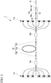
- Fig. 1 is a diagram showing a main configuration of a laser apparatus according to the first embodiment of the present invention.
- the laser apparatus 1 of the present embodiment includes an excitation light source (forward excitation light source) 11a, an excitation light source (backward excitation light source) 11b, a first combiner 12a, a second combiner 12b, a resonator 13, an optical device 14, and an output end 15.
- Such a laser apparatus 1 is a bidirectional excitation fiber laser apparatus including an excitation light source 11a and an excitation light source 11b.
- the longitudinal direction of the optical fiber 20 (see Fig. 2 ) included in the optical device 14 of the laser apparatus 1 is simply referred to as the "longitudinal direction”.
- the output end 15 side in the longitudinal direction is referred to as "+X side”
- the resonator 13 side is referred to as "-X side”.
- the excitation light source 11a side may be referred to as "forward” and the excitation light source 11b side may be referred to as "backward” when viewed from the amplification fiber 13a of the resonator 13.
- excitation light sources 11a and excitation light sources 11b are arranged with the resonator 13 interposed therebetween.
- the excitation light source 11a emits excitation light (forward excitation light) toward the resonator 13, and the excitation light source 11b emits excitation light (backward excitation light) toward the resonator 13.
- a laser diode can be used as the excitation light source 11a and the excitation light source 11b.
- the first combiner 12a and the second combiner 12b are arranged on both sides of the resonator 13.
- the first combiner 12a couples the excitation light emitted by each of the excitation light sources 11a to one optical fiber and directs the excitation light to the resonator 13.
- the second combiner 12b couples the excitation light emitted by each of the excitation light sources 11b to one optical fiber and directs the excitation light to the resonator 13.
- the resonator 13 includes an amplification fiber 13a, a High Reflectivity-Fiber Bragg Grating (HR-FBG) 13b, and an Output Coupler-Fiber Bragg Grating (OC-FBG) 13c.
- the resonator 13 generates signal light, which is a laser beam, by the excitation light emitted from the excitation light source 11a and the excitation light source 11b.
- the amplification fiber 13a has a core to which one or more kinds of active elements are added, a first cladding covering the core, a second cladding covering the first cladding, and a protective coating covering the second cladding. That is, the amplification fiber 13a is a double cladding fiber.
- the active element added to the core for example, a rare earth element such as erbium (Er), ytterbium (Yb), or neodymium (Nd) is used. These active elements emit light in the excitation state. Silica glass or the like can be used as the core and the first cladding.
- a resin such as a polymer can be used.
- the protective coating a resin material such as an acrylic resin or a silicone resin can be used.
- the HR-FBG (first FBG) 13b is formed in the core of the optical fiber which is fusion-spliced to a front end portion of the amplification fiber 13a.
- the HR-FBG 13b is adjusted so as to reflect light having a wavelength of signal light with a reflectance of approximately 100% among the light emitted by the active element of the excitation amplification fiber 13a.
- the HR-FBG 13b has a structure in which a portion having a high refractive index is repeated at regular intervals along the longitudinal direction thereof.
- the OC-FBG (second FBG) 13c is formed in the core of the optical fiber fused to a rear end portion of the amplification fiber 13a.
- the OC-FBG 13c has almost the same structure as the HR-FBG 13b; however, is adjusted to reflect light with a lower reflectance than the HR-FBG 13b.
- the OC-FBG 13c is adjusted so that the reflectance with respect to the light having a wavelength of the signal light is approximately 10 to 20%.
- the signal light reflected by the HR-FBG 13b and the OC-FBG 13c reciprocates in the longitudinal direction of the amplification fiber 13a.
- the signal light is amplified along with the reciprocation to become laser light.
- the light is amplified and the laser beam is generated.
- a portion of the laser beam passes through the OC-FBG 13c, reaches the output end 15 via the optical device 14, and is output to the outside.
- the optical device 14 includes a slanted FBG 14a and a cladding mode removal portion 14b.
- the cladding mode removal portion 14b is provided on the +X side and the -X side of the slanted FBG 14a so as to sandwich the slanted FBG 14a in the longitudinal direction.
- Such an optical device 14 is provided to remove cladding mode light including SRS light propagating in the core 20a (see Fig. 2 ) of the optical fiber 20 and SRS light propagating in the first cladding 20b of the optical fiber 20.
- the optical device 14 is arranged between the resonator 13 and the output end 15.
- the optical device 14 is arranged in a region where the residual excitation light of the excitation light emitted from the excitation light source 11a and the excitation light source 11b does not substantially reach.
- the "where the residual excitation light does not substantially reach" in the present embodiment is, for example, a portion of the laser apparatus 1 located on the +X side of the second combiner 12b. In the region, since the excitation light is sufficiently absorbed by the core of the amplification fiber 13a forming the resonator 13, it is possible to avoid a situation in which the excitation light is unexpectedly removed by the optical device 14.
- Another optical fiber (an optical fiber at a resonator side) is fusion-spliced to an end portion of the -X side of the optical fiber 20 included in the optical device 14, and another optical fiber (an optical fiber at an output side) is fusion-spliced to an end portion of the +X side.
- a fusion-spliced portion between the optical fiber 20 and the optical fiber on the resonator side is referred to as a first spliced portion A1
- a fusion-spliced portion between the optical fiber 20 and the optical fiber on the output side is referred to as a second spliced portion A2.
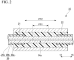
- Fig. 2 is a cross-sectional view showing a portion of the configuration of the optical device according to the first embodiment of the present invention.
- the cross-sectional view shown in Fig. 2 shows only the portion where the slanted FBG 14a is formed and the vicinity thereof.
- the portion where the cladding mode removal portion 14b is formed and the vicinity thereof are not shown.
- the optical device 14 includes an optical fiber 20, a high refractive index material 21, and a heat dissipation member 22.
- the optical fiber 20 has a core 20a on which a slanted FBG 14a is formed, a first cladding 20b, and a second cladding 20c. That is, the optical fiber 20 is a double cladding fiber having a core 20a on which a slanted FBG 14a is formed.
- the optical fiber 20 has a protective coating that covers the second cladding 20c; however, the protective coating is not shown in Fig. 2 .
- the core 20a and the first cladding 20b of the optical fiber 20 for example, silica glass or the like can be used.
- a resin such as a polymer can be used as the second cladding 20c of the optical fiber 20. That is, a double cladding fiber having a glass cladding formed of silica glass and a polymer cladding formed of a polymer material can be used as the optical fiber 20.
- the first cladding 20b covers the core 20a and has a lower refractive index than the core 20a.
- the second cladding 20c covers the first cladding 20b and has a lower refractive index than the first cladding 20b.
- a resin material such as an acrylic resin or a silicone resin can be used. These resin materials used as protective coatings generally absorb light and generate heat.
- the slanted FBG 14a is formed in the core 20a of the optical fiber 20 and is for binding (mode coupling) the SRS light propagating in the core 20a to the first cladding 20b.
- the slanted FBG 14a is formed by partially irradiating the core 20a of the optical fiber 20 with a processing light ray (ultraviolet laser beam or the like) to modulate the refractive index of the core 20a in the longitudinal direction.
- a processing light ray ultraviolet laser beam or the like
- the second cladding 20c and the protective coating are partially removed, and the core 20a is irradiated with a light beam for processing through the removal portion.
- the slanted FBG 14a is configured so as to transmit light in the wavelength band (for example, 1070 nm) of the signal light used as the laser light and release the light in the wavelength band (for example, 1125 nm) of the SRS light from the core 20a toward the first cladding 20b. Although the slanted FBG 14a transmits most of the signal light propagating through the core 20a, it reflects a portion of the signal light. The signal light reflected by the slanted FBG 14a is coupled to the first cladding 20b.
- the wavelength band for example, 1070 nm
- the slanted FBG 14a transmits most of the signal light propagating through the core 20a, it reflects a portion of the signal light.
- the signal light reflected by the slanted FBG 14a is coupled to the first cladding 20b.
- the distance between the refractive index modulation portions in the longitudinal direction be non-uniform.
- the wavelength band of the light removed from the core 20a by the slanted FBG 14a increases.
- the SRS light can be more reliably released toward the first cladding 20b. Therefore, by selectively removing a portion of the SRS light from the core 20a and coupling to the first cladding 20b, it is possible to stabilize the quality of the signal light and prevent damage to the excitation light source 11a and the excitation light source 11b.
- the portion from which the second cladding 20c and the like have been removed is covered with the high refractive index material 21 after the slanted FBG 14a is formed. That is, in the first cladding 20b, the outer peripheral surface of the removal portion PT2 including the portion PT1 covering the region where the slanted FBG 14a is formed in the core 20a and from which the second cladding 20c is removed is covered with the high refractive index material 21. In the example shown in Fig. 2 , the outer peripheral surface of the second cladding 20c arranged inside the heat dissipation member 22 is also covered with the high refractive index material 21.
- Such a high refractive index material 21 is provided to prevent the signal light coupled to the first cladding 20b by the slanted FBG 14a formed on the core 20a from entering the second cladding 20c.
- the second cladding 20c is covered with a protective coating, and when the signal light coupled to the first cladding 20b is incident on the second cladding 20c, the protective coating may generate heat and burn out.
- the high refractive index material 21 is provided in order to prevent such burning out of the protective coating.
- the high refractive index material 21 a resin material having a higher refractive index than the second cladding 20c and having high transparency to signal light and SRS light can be used.
- the refractive index of the resin material constituting the high refractive index material 21 may be equal to or higher than the refractive index of the first cladding 20b. The principle by which the signal light coupled to the first cladding 20b can be prevented from being incident on the second cladding 20c by providing such a high refractive index material 21 will be described later.
- the heat dissipation member 22 is formed longer than the length of the removal portion PT2 in the longitudinal direction, and is provided so as to cover the high refractive index material 21.
- the heat dissipation member 22 is provided to absorb the SRS light and the signal light through the high refractive index material 21 and dissipate the heat generated by the absorption.
- the heat dissipation member 22 is, for example, a member having a square cylinder shape or a cylindrical shape, and is formed of, for example, a metal such as aluminum whose inner surface is black anodized.
- the inner surface of the heat dissipation member 22 is treated with black alumite in order to prevent reflection of the SRS light and the signal light incident on the inner surface.
- the cladding mode removal portion 14b shown in Fig. 1 is a so-called cladding mode stripper.
- the cladding mode stripper is formed by, for example, intermittently removing a portion of the second cladding 20c of the optical fiber 20 and the protective coating (not shown) along the longitudinal direction, and covering the removal portion with a high refractive index resin or the like.
- Such a cladding mode stripper can remove cladding mode light including SRS light from the inside of the first cladding 20b to a high refractive index resin or the like.
- the basic reflection wavelength of the slanted FBG 14a is ⁇ 0, and the wavelength difference between the wavelength of the signal light propagating in the core 20a and ⁇ 0 is ⁇ .
- the refractive index of the core 20a is nc, and the refractive index of the high refractive index material 21 is n.
- the wavelength band of the signal light propagating in the core 20a is, for example, a central wavelength of 1070 nm and a wavelength width of about several tens of nm. Therefore, it should be noted that the above-mentioned wavelength difference ⁇ also has a width similar to the above-mentioned wavelength width.
- the signal light propagating in the core 20a is coupled to the first cladding 20b when the following equation (1) is satisfied. ⁇ ⁇ ⁇ nc ⁇ n / 2 ⁇ nc ⁇ ⁇ 0
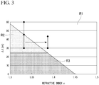
- Fig. 3 is a diagram showing the relationship between the wavelength difference ⁇ and the refractive index n of the high refractive index material in the first embodiment of the present invention.
- the wavelength difference ⁇ is on the vertical axis
- the refractive index n of the high refractive index material 21 is on the horizontal axis.
- the basic reflection wavelength ⁇ 0 of the slanted FBG 14a is set to 1120 nm.
- the refractive index difference between the core 20a and the first cladding 20b is sufficiently smaller than the refractive index difference between the first cladding 20b and the second cladding 20c
- the refractive index nc of the core 20a and the refractive index of the first cladding 20b is 1.45 (refractive index of quartz)
- the refractive index of the second cladding 20c is 1.38 (refractive index of polymer material).
- the graph shown in Fig. 3 is roughly divided into regions R1 and regions R2 and R3 according to the relationship between the wavelength difference ⁇ and the refractive index n of the high refractive index material 21.
- the region R1 is a region where the above equation (1) is not satisfied, and the regions R2 and R3 are regions where the above equation (1) is satisfied. That is, the region R1 is a region where the signal light propagating in the core 20a is not coupled to the first cladding 20b, and the regions R2 and R3 are regions where the signal light propagating in the core 20a is coupled to the first cladding 20b.
- the region R2 is a region where the signal light coupled to the first cladding 20b is incident on the second cladding 20c
- the region R3 is a region where the signal light coupled to the first cladding 20b propagates through the first cladding 20b without being incident on the second cladding 20c.
- Fig. 4 is a diagram schematically showing a traveling path of signal light reflected by a slanted FBG in the first embodiment of the present invention.
- the signal light reflected by the slanted FBG 14a is, for example, the traveling path P1 shown in Fig. 4 , and the light is incident on the heat dissipation member 22 via the first cladding 20b and the high refractive index material 21.
- the signal light reflected by the slanted FBG 14a is incident on the second cladding 20c when the signal light propagates in the first cladding 20b and reaches the second cladding 20c as the traveling path P2 shown in Fig. 4 , for example.
- the signal light reflected by the slanted FBG 14a is, for example, the traveling path P3 shown in Fig. 4 , and is propagated through the first cladding 20b without being incident on the second cladding 20c.
- the signal light reflected by the slanted FBG 14a passes through the traveling path P1 shown in Fig. 4 , the signal light is incident on the heat dissipation member 22 and absorbed.
- the signal light reflected by the slanted FBG 14a passes through the traveling path P3 shown in Fig. 4 , the signal light is removed by the cladding mode removal portion 14b shown in Fig. 1 .
- the protective coating covering the second cladding 20c may generate heat and burn out. In order to prevent burning out due to such heat generation, the relationship between the wavelength difference ⁇ and the refractive index n of the high refractive index material 21 may not be included in the region R2 shown in Fig. 3 .
- the refractive index n of the high refractive index material 21 is 1.33, which is lower than that of the second cladding 20c, there is a case that the relationship between the wavelength difference ⁇ and the refractive index n of the high refractive index material 21 is included in the region R2 as shown in Fig. 3 .
- the refractive index n of the high refractive index material 21 is higher than that of the second cladding 20c, the relationship between the wavelength difference ⁇ and the refractive index n of the high refractive index material 21 is not included in the region R2 as shown in Fig. 3 .
- the refractive index n of the high refractive index material 21 is higher than that of the first cladding 20b, the relationship between the wavelength difference ⁇ and the refractive index n of the high refractive index material 21 is not included in the region R3 as shown in Fig. 3 . Therefore, the refractive index n of the high refractive index material 21 is higher than the refractive index of the second cladding 20c.
- the outer peripheral surface of the removal portion PT2 including the portion PT1 covering the region where the slanted FBG 14a is formed in the core 20a and from which the second cladding 20c is removed is covered with the high refractive index material 21.
- the SRS light propagating in the first cladding 20b is also removed by the combination of the slanted FBG 14a provided in the optical device 14 and the cladding mode removal portion 14b. Therefore, it is possible to prevent the protective coating from being irradiated with SRS light and burning out due to heat generation, or the SRS light reaching the excitation light source 11a and the excitation light source 11b and damaging the excitation light source 11a and the excitation light source 11.
- Fig. 5 is a cross-sectional view showing a modification of the optical device according to the first embodiment of the present invention.
- the optical device 14 shown in Fig. 5 includes a reinforcement member 23 provided between the heat dissipation member 22 and the second cladding 20c on the outer sides of both ends of the removal portion PT2 in the longitudinal direction.
- the reinforcement member 23 enhances the adhesion strength between the heat dissipation member 22 and the second cladding 20c.
- a resin having a refractive index lower than that of the second cladding 20c can be used.
- Fig. 6 is a diagram showing a modified example of the laser apparatus according to the first embodiment of the present invention.
- the laser apparatus 1 shown in Fig. 6 includes an optical device 14 in which the cladding mode removal portion 14b is provided only on the -X side of the slanted FBG 14a. That is, in the optical device 14 provided in the laser apparatus 1, the cladding mode removal portion 14b may be provided only on the -X side of the slanted FBG 14a, or on both sides (+X side and -X side) of the slanted FBG 14a.
- Fig. 7 is a diagram showing a main configuration of a laser apparatus according to the second embodiment of the present invention.
- the same reference numerals are given to the configurations similar to those shown in Fig. 1 .
- the description of the same configuration as that described with reference to Fig. 1 will be omitted, and only the different portions will be described.
- the laser apparatus 2 of the present embodiment includes an excitation light source 11a, a first combiner 12a, a resonator 13, an optical device 14, and an output end 15.
- a laser apparatus 2 is a one-sided excitation apparatus that does not have an excitation light source (backward excitation light source) 11b. That is, the laser apparatus 2 is a forward excitation fiber laser apparatus.
- the resonator 13 includes an amplification fiber 13a and the HR-FBG (first FBG) 13b and the OC- FBG (second FBG) 13c.
- the optical device 14 is arranged between the OC-FBG 13c forming the resonator 13 and the output end 15. Also in the present embodiment, in order to prevent the excitation light from being unintentionally removed, the optical device 14 is arranged in a region where the residual excitation light does not substantially reach.
- the "region where the residual excitation light does not substantially reach" in the present embodiment is, for example, a portion of the laser apparatus 2 located on the output end 15 side of the OC-FBG 13c. Since the excitation light is sufficiently absorbed by the core of the amplification fiber 13a forming the resonator 13, such a region is suitable as a position for providing the optical device 14. Although detailed description will be omitted, the laser apparatus 2 of the present embodiment can also obtain the same effects as those of the first embodiment.
- Fig. 8 is a diagram showing a modification of the laser apparatus according to the second embodiment of the present invention.
- the laser apparatus 2 shown in Fig. 8 has a configuration in which the optical device 14 is arranged between the amplification fiber 13a and the OC-FBG 13c, that is, in the resonator 13.
- the second embodiment is performed by arranging the optical device 14 in a region where the excitation light is sufficiently absorbed by the core of the amplification fiber 13a and the residual excitation light does not substantially reach. The same effect as described above can be obtained.
- the present invention is not limited to the above embodiments and can be freely modified within the scope of the present invention.
- the laser apparatuses 1 and 2 of the first and second embodiments described above have one output end 15; however, an optical fiber or the like may be further spliced to the tip of the output end 15.
- a beam combiner may be spliced to the tip of the output end 15 so as to bundle the laser beams from a plurality of laser apparatuses.
- the optical devices 14 provided in the laser apparatuses 1 and 2 of the first and second embodiments described above may be used in a Master Oscillator Power Amplifier (MOPA) fiber laser apparatus.
- the optical device 14 is a laser apparatus such as a semiconductor laser (DDL: Direct Diode Laser) or a disk laser in which the resonator is composed of a non-optical fiber and the laser beam emitted from the resonator is focused on the optical fiber.
- DDL Direct Diode Laser
Landscapes
- Physics & Mathematics (AREA)
- Electromagnetism (AREA)
- Optics & Photonics (AREA)
- Engineering & Computer Science (AREA)
- Plasma & Fusion (AREA)
- General Physics & Mathematics (AREA)
- Lasers (AREA)
- Optical Fibers, Optical Fiber Cores, And Optical Fiber Bundles (AREA)
Abstract
Description
- The present invention relates to an optical device and laser apparatus.
- The present application claims priority based on
Japanese Patent Application No. 2019-028636 - Currently, laser apparatuses are used in various fields such as processing fields, automobile fields, and medical fields. In recent years, in the processing field, a fiber laser apparatus having excellent beam quality and light-collecting property as compared with a conventional laser apparatus (for example, a carbon dioxide gas laser apparatus) has attracted attention. The maximum output of such a fiber laser apparatus is limited by induced Raman scattering (SRS) that occurs non-linearly with respect to the laser output.
- The following
Patent Document 1 discloses a technique for reducing SRS light by forming a slanted Fiber Bragg Grating (FBG) in the core of a fiber laser apparatus. According to such a technique, SRS light can be selectively removed from the light propagating in the core. As a result, it is possible to stabilize the signal light propagating in the core and prevent damage to the excitation light source. - [Patent Document 1]
United States Patent No. 9634462 - In a high-power fiber laser apparatus, when a slanted FBG is formed on the core, high-power SRS light removed from the core is guided in the cladding. When high-power SRS light is intensively applied to, for example, the protective coating covering the cladding, it is possible that the protective coating generates heat and burns out. Alternatively, when SRS light guided in the cladding reaches the excitation light source, the excitation light source may be damaged.
- In addition, in a high-power fiber laser apparatus, when a slanted FBG is formed on the core, it is conceivable that a portion of the signal light propagating in the core leaks to the cladding and is guided in the cladding. When such signal light is applied to, for example, the protective coating covering the cladding, it is possible that the protective coating generates heat and burns out, as in the case where high-power SRS light is intensively irradiated.
- The present invention has been made in view of the above circumstances, and an optical device and a laser apparatus are provided that are capable of preventing the protective coating from burning out due to heat generation by effectively removing the light guided in the cladding when a slanted FBG is formed on the core.
- In order to solve the above-described problems, an optical device (14) according to one aspect of the present invention includes a core (20a), a first cladding (20b) that covers the core and has a lower refractive index than the core, a second cladding (20c) that covers the first cladding and has a lower refractive index than the first cladding, a slanted FBG (14a) that is formed in the core and couples SRS light propagating through the core to the first cladding, and a high refractive index material (21) that has a higher refractive index than the second cladding and which covers an outer peripheral surface of a removal portion (PT2) where the second cladding is removed and a portion (PT1) of the first cladding which covers the region where the slanted FBG is formed in the core.
- In the optical device according to one aspect of the present invention, the high refractive index material may have a higher refractive index than the first cladding.
- The optical device according to one aspect of the present invention may include a heat dissipation member (22) that covers the high refractive index material.
- In the optical device according to one aspect of the present invention, the heat dissipation member may dissipate heat generated by absorption of SRS light and signal light through the high refractive index material.
- The optical device according to one aspect of the present invention may further include a reinforcement member (23) provided between the heat dissipation member and the second cladding outside of both ends of the removal portion in a longitudinal direction of the first cladding, where the heat dissipation member is formed longer than the length of the removal portion in the longitudinal direction of the first cladding.
- The optical device according to one aspect of the present invention may include at least one cladding mode removal portion (14b) that removes cladding mode light, which includes SRS light coupled from the core to the first cladding by the slanted FBG, from the inside of the first cladding.
- A laser apparatus (1, 2) according to one aspect of the present invention may include an excitation light source (11a, 11b) that emits excitation light, a resonator (13) that generates signal light that is laser light by the excitation light emitted from the excitation light source, and an optical device (14) according to any one of the above that is arranged between the resonator and the output end (15) of the signal light.
- In the laser apparatus according to one aspect of the present invention, the optical device may be arranged in a region where the residual excitation light of the excitation light emitted from the excitation light source substantially does not reach.
- In the laser apparatus according to one aspect of the present invention, the laser apparatus may be a bidirectional excitation fiber laser apparatus including a forward excitation light source (11a) and a backward excitation light source (11b) as the excitation light source, and may include a first combiner (12a) provided between the resonator and the forward excitation light source and a second combiner (12b) provided between the resonator and the backward excitation light source, and the region is a portion located on the output end side of the second combiner.
- In the laser apparatus according to one aspect of the present invention, the laser apparatus may be a forward excitation fiber laser apparatus, the resonator (13) may include an amplification fiber (13a) in which an active element activated by excitation light is added to the core, a first FBG (13b) provided between the first end of the amplification fiber and the excitation light source, and a second FBG (13c) provided between the second end of the amplification fiber and the output end, and the region is closer to the output end side than the second FBG.
- According to the present invention, when a slanted FBG is formed on the core, it is possible to effectively remove light guided in the cladding and prevent the protective coating from burning out due to heat generation.
-
-
Fig. 1 is a diagram showing a main structure of a laser apparatus according to a first embodiment of the present invention. -
Fig. 2 is a cross-sectional view showing a portion of a configuration of an optical device according to a first embodiment of the present invention. -
Fig. 3 is a diagram showing a relationship between a wavelength difference and a refractive index n of a high refractive index material in a first embodiment of the present invention. -
Fig. 4 is a diagram schematically showing a traveling path of signal light reflected by a slant FBG in a first embodiment of the present invention. -
Fig. 5 is a cross-sectional view showing a modification of an optical device according to a first embodiment of the present invention. -
Fig. 6 is a diagram showing a modification of a laser apparatus according to a first embodiment of the present invention. -
Fig. 7 is a diagram showing a main structure of a laser apparatus according to a second embodiment of the present invention. -
Fig. 8 is a diagram showing a modification of a laser apparatus according to a second embodiment of the present invention. - Hereinafter, the optical device and the laser apparatus according to the embodiment of the present invention will be described in detail with reference to the drawings. In addition, in the drawings used in the following description, for the sake of clarity, characteristic portions may be enlarged and shown, and the dimensional ratios and the like of each component may not be the same as the actual ones. In addition, the present invention is not limited to the following embodiments.
-
Fig. 1 is a diagram showing a main configuration of a laser apparatus according to the first embodiment of the present invention. As shown inFig. 1 , thelaser apparatus 1 of the present embodiment includes an excitation light source (forward excitation light source) 11a, an excitation light source (backward excitation light source) 11b, afirst combiner 12a, asecond combiner 12b, aresonator 13, anoptical device 14, and anoutput end 15. Such alaser apparatus 1 is a bidirectional excitation fiber laser apparatus including anexcitation light source 11a and anexcitation light source 11b. - In the following, the longitudinal direction of the optical fiber 20 (see
Fig. 2 ) included in theoptical device 14 of thelaser apparatus 1 is simply referred to as the "longitudinal direction". In addition, when viewed from theoptical fiber 20, theoutput end 15 side in the longitudinal direction is referred to as "+X side", and theresonator 13 side is referred to as "-X side". Furthermore, theexcitation light source 11a side may be referred to as "forward" and theexcitation light source 11b side may be referred to as "backward" when viewed from theamplification fiber 13a of theresonator 13. - As shown in
Fig. 1 , a plurality ofexcitation light sources 11a andexcitation light sources 11b are arranged with theresonator 13 interposed therebetween. Theexcitation light source 11a emits excitation light (forward excitation light) toward theresonator 13, and theexcitation light source 11b emits excitation light (backward excitation light) toward theresonator 13. As theexcitation light source 11a and theexcitation light source 11b, for example, a laser diode can be used. - The
first combiner 12a and thesecond combiner 12b are arranged on both sides of theresonator 13. Thefirst combiner 12a couples the excitation light emitted by each of theexcitation light sources 11a to one optical fiber and directs the excitation light to theresonator 13. Thesecond combiner 12b couples the excitation light emitted by each of theexcitation light sources 11b to one optical fiber and directs the excitation light to theresonator 13. - The
resonator 13 includes anamplification fiber 13a, a High Reflectivity-Fiber Bragg Grating (HR-FBG) 13b, and an Output Coupler-Fiber Bragg Grating (OC-FBG) 13c. Theresonator 13 generates signal light, which is a laser beam, by the excitation light emitted from theexcitation light source 11a and theexcitation light source 11b. - The
amplification fiber 13a has a core to which one or more kinds of active elements are added, a first cladding covering the core, a second cladding covering the first cladding, and a protective coating covering the second cladding. That is, theamplification fiber 13a is a double cladding fiber. As the active element added to the core, for example, a rare earth element such as erbium (Er), ytterbium (Yb), or neodymium (Nd) is used. These active elements emit light in the excitation state. Silica glass or the like can be used as the core and the first cladding. As the second cladding, a resin such as a polymer can be used. As the protective coating, a resin material such as an acrylic resin or a silicone resin can be used. - The HR-FBG (first FBG) 13b is formed in the core of the optical fiber which is fusion-spliced to a front end portion of the
amplification fiber 13a. The HR-FBG 13b is adjusted so as to reflect light having a wavelength of signal light with a reflectance of approximately 100% among the light emitted by the active element of theexcitation amplification fiber 13a. The HR-FBG 13b has a structure in which a portion having a high refractive index is repeated at regular intervals along the longitudinal direction thereof. - The OC-FBG (second FBG) 13c is formed in the core of the optical fiber fused to a rear end portion of the
amplification fiber 13a. The OC-FBG 13c has almost the same structure as the HR-FBG 13b; however, is adjusted to reflect light with a lower reflectance than the HR-FBG 13b. For example, the OC-FBG 13c is adjusted so that the reflectance with respect to the light having a wavelength of the signal light is approximately 10 to 20%. - In the
amplification fiber 13a, the signal light reflected by the HR-FBG 13b and the OC-FBG 13c reciprocates in the longitudinal direction of theamplification fiber 13a. The signal light is amplified along with the reciprocation to become laser light. In such a manner, in theresonator 13, the light is amplified and the laser beam is generated. A portion of the laser beam passes through the OC-FBG 13c, reaches theoutput end 15 via theoptical device 14, and is output to the outside. - The
optical device 14 includes aslanted FBG 14a and a claddingmode removal portion 14b. The claddingmode removal portion 14b is provided on the +X side and the -X side of the slantedFBG 14a so as to sandwich theslanted FBG 14a in the longitudinal direction. Such anoptical device 14 is provided to remove cladding mode light including SRS light propagating in thecore 20a (seeFig. 2 ) of theoptical fiber 20 and SRS light propagating in thefirst cladding 20b of theoptical fiber 20. - The
optical device 14 is arranged between theresonator 13 and theoutput end 15. In particular, theoptical device 14 is arranged in a region where the residual excitation light of the excitation light emitted from theexcitation light source 11a and theexcitation light source 11b does not substantially reach. The "where the residual excitation light does not substantially reach" in the present embodiment is, for example, a portion of thelaser apparatus 1 located on the +X side of thesecond combiner 12b. In the region, since the excitation light is sufficiently absorbed by the core of theamplification fiber 13a forming theresonator 13, it is possible to avoid a situation in which the excitation light is unexpectedly removed by theoptical device 14. - Another optical fiber (an optical fiber at a resonator side) is fusion-spliced to an end portion of the -X side of the
optical fiber 20 included in theoptical device 14, and another optical fiber (an optical fiber at an output side) is fusion-spliced to an end portion of the +X side. Hereinafter, a fusion-spliced portion between theoptical fiber 20 and the optical fiber on the resonator side is referred to as a first spliced portion A1, and a fusion-spliced portion between theoptical fiber 20 and the optical fiber on the output side is referred to as a second spliced portion A2. -
Fig. 2 is a cross-sectional view showing a portion of the configuration of the optical device according to the first embodiment of the present invention. The cross-sectional view shown inFig. 2 shows only the portion where theslanted FBG 14a is formed and the vicinity thereof. InFig. 2 , the portion where the claddingmode removal portion 14b is formed and the vicinity thereof are not shown. - As shown in
Fig. 2 , theoptical device 14 includes anoptical fiber 20, a highrefractive index material 21, and aheat dissipation member 22. Theoptical fiber 20 has a core 20a on which aslanted FBG 14a is formed, afirst cladding 20b, and asecond cladding 20c. That is, theoptical fiber 20 is a double cladding fiber having a core 20a on which aslanted FBG 14a is formed. - The
optical fiber 20 has a protective coating that covers thesecond cladding 20c; however, the protective coating is not shown inFig. 2 . - As the
core 20a and thefirst cladding 20b of theoptical fiber 20, for example, silica glass or the like can be used. As thesecond cladding 20c of theoptical fiber 20, a resin such as a polymer can be used. That is, a double cladding fiber having a glass cladding formed of silica glass and a polymer cladding formed of a polymer material can be used as theoptical fiber 20. - The
first cladding 20b covers thecore 20a and has a lower refractive index than thecore 20a. Thesecond cladding 20c covers thefirst cladding 20b and has a lower refractive index than thefirst cladding 20b. As the protective coating (not shown), a resin material such as an acrylic resin or a silicone resin can be used. These resin materials used as protective coatings generally absorb light and generate heat. - The
slanted FBG 14a is formed in thecore 20a of theoptical fiber 20 and is for binding (mode coupling) the SRS light propagating in thecore 20a to thefirst cladding 20b. Theslanted FBG 14a is formed by partially irradiating thecore 20a of theoptical fiber 20 with a processing light ray (ultraviolet laser beam or the like) to modulate the refractive index of thecore 20a in the longitudinal direction. In the present embodiment, in order to form theslanted FBG 14a, thesecond cladding 20c and the protective coating (not shown) are partially removed, and thecore 20a is irradiated with a light beam for processing through the removal portion. - The
slanted FBG 14a is configured so as to transmit light in the wavelength band (for example, 1070 nm) of the signal light used as the laser light and release the light in the wavelength band (for example, 1125 nm) of the SRS light from thecore 20a toward thefirst cladding 20b. Although theslanted FBG 14a transmits most of the signal light propagating through thecore 20a, it reflects a portion of the signal light. The signal light reflected by theslanted FBG 14a is coupled to thefirst cladding 20b. - In the
slanted FBG 14a, it is desirable that the distance between the refractive index modulation portions in the longitudinal direction be non-uniform. As a result, the wavelength band of the light removed from thecore 20a by the slantedFBG 14a increases. In such a manner, the SRS light can be more reliably released toward thefirst cladding 20b. Therefore, by selectively removing a portion of the SRS light from thecore 20a and coupling to thefirst cladding 20b, it is possible to stabilize the quality of the signal light and prevent damage to theexcitation light source 11a and theexcitation light source 11b. - The portion from which the
second cladding 20c and the like have been removed (removal portion PT2) is covered with the highrefractive index material 21 after theslanted FBG 14a is formed. That is, in thefirst cladding 20b, the outer peripheral surface of the removal portion PT2 including the portion PT1 covering the region where theslanted FBG 14a is formed in thecore 20a and from which thesecond cladding 20c is removed is covered with the highrefractive index material 21. In the example shown inFig. 2 , the outer peripheral surface of thesecond cladding 20c arranged inside theheat dissipation member 22 is also covered with the highrefractive index material 21. - Such a high
refractive index material 21 is provided to prevent the signal light coupled to thefirst cladding 20b by the slantedFBG 14a formed on thecore 20a from entering thesecond cladding 20c. As described above, thesecond cladding 20c is covered with a protective coating, and when the signal light coupled to thefirst cladding 20b is incident on thesecond cladding 20c, the protective coating may generate heat and burn out. The highrefractive index material 21 is provided in order to prevent such burning out of the protective coating. - As the high
refractive index material 21, a resin material having a higher refractive index than thesecond cladding 20c and having high transparency to signal light and SRS light can be used. The refractive index of the resin material constituting the highrefractive index material 21 may be equal to or higher than the refractive index of thefirst cladding 20b. The principle by which the signal light coupled to thefirst cladding 20b can be prevented from being incident on thesecond cladding 20c by providing such a highrefractive index material 21 will be described later. - The
heat dissipation member 22 is formed longer than the length of the removal portion PT2 in the longitudinal direction, and is provided so as to cover the highrefractive index material 21. Theheat dissipation member 22 is provided to absorb the SRS light and the signal light through the highrefractive index material 21 and dissipate the heat generated by the absorption. Theheat dissipation member 22 is, for example, a member having a square cylinder shape or a cylindrical shape, and is formed of, for example, a metal such as aluminum whose inner surface is black anodized. The inner surface of theheat dissipation member 22 is treated with black alumite in order to prevent reflection of the SRS light and the signal light incident on the inner surface. - The cladding
mode removal portion 14b shown inFig. 1 is a so-called cladding mode stripper. Here, the cladding mode stripper is formed by, for example, intermittently removing a portion of thesecond cladding 20c of theoptical fiber 20 and the protective coating (not shown) along the longitudinal direction, and covering the removal portion with a high refractive index resin or the like. Such a cladding mode stripper can remove cladding mode light including SRS light from the inside of thefirst cladding 20b to a high refractive index resin or the like. - The basic reflection wavelength of the
slanted FBG 14a is λ0, and the wavelength difference between the wavelength of the signal light propagating in thecore 20a and λ0 is Δλ. In addition, the refractive index of thecore 20a is nc, and the refractive index of the highrefractive index material 21 is n. The wavelength band of the signal light propagating in thecore 20a is, for example, a central wavelength of 1070 nm and a wavelength width of about several tens of nm. Therefore, it should be noted that the above-mentioned wavelength difference Δλ also has a width similar to the above-mentioned wavelength width. - The signal light propagating in the
core 20a is coupled to thefirst cladding 20b when the following equation (1) is satisfied.
-
Fig. 3 is a diagram showing the relationship between the wavelength difference Δλ and the refractive index n of the high refractive index material in the first embodiment of the present invention. In the graph shown inFig. 3 , the wavelength difference Δλ is on the vertical axis, and the refractive index n of the highrefractive index material 21 is on the horizontal axis. InFig. 3 , the basic reflection wavelength λ0 of theslanted FBG 14a is set to 1120 nm. In addition, since the refractive index difference between the core 20a and thefirst cladding 20b is sufficiently smaller than the refractive index difference between thefirst cladding 20b and thesecond cladding 20c, the refractive index nc of thecore 20a and the refractive index of thefirst cladding 20b is 1.45 (refractive index of quartz), and the refractive index of thesecond cladding 20c is 1.38 (refractive index of polymer material). The graph shown inFig. 3 is roughly divided into regions R1 and regions R2 and R3 according to the relationship between the wavelength difference Δλ and the refractive index n of the highrefractive index material 21. - The region R1 is a region where the above equation (1) is not satisfied, and the regions R2 and R3 are regions where the above equation (1) is satisfied. That is, the region R1 is a region where the signal light propagating in the
core 20a is not coupled to thefirst cladding 20b, and the regions R2 and R3 are regions where the signal light propagating in thecore 20a is coupled to thefirst cladding 20b. Here, the region R2 is a region where the signal light coupled to thefirst cladding 20b is incident on thesecond cladding 20c, whereas the region R3 is a region where the signal light coupled to thefirst cladding 20b propagates through thefirst cladding 20b without being incident on thesecond cladding 20c. -
Fig. 4 is a diagram schematically showing a traveling path of signal light reflected by a slanted FBG in the first embodiment of the present invention. When the relationship between the wavelength difference Δλ and the refractive index n of the highrefractive index material 21 is included in the region R1, the signal light reflected by theslanted FBG 14a is, for example, the traveling path P1 shown inFig. 4 , and the light is incident on theheat dissipation member 22 via thefirst cladding 20b and the highrefractive index material 21. - When the relationship between the wavelength difference Δλ and the refractive index n of the high
refractive index material 21 is included in the region R2, the signal light reflected by theslanted FBG 14a is incident on thesecond cladding 20c when the signal light propagates in thefirst cladding 20b and reaches thesecond cladding 20c as the traveling path P2 shown inFig. 4 , for example. When the relationship between the wavelength difference Δλ and the refractive index n of the highrefractive index material 21 is included in the region R3, the signal light reflected by theslanted FBG 14a is, for example, the traveling path P3 shown inFig. 4 , and is propagated through thefirst cladding 20b without being incident on thesecond cladding 20c. - When the signal light reflected by the slanted
FBG 14a passes through the traveling path P1 shown inFig. 4 , the signal light is incident on theheat dissipation member 22 and absorbed. In addition, when the signal light reflected by the slantedFBG 14a passes through the traveling path P3 shown inFig. 4 , the signal light is removed by the claddingmode removal portion 14b shown inFig. 1 . On the other hand, when the signal light reflected by the slantedFBG 14a passes through the traveling path P2 shown inFig. 4 , the protective coating covering thesecond cladding 20c may generate heat and burn out. In order to prevent burning out due to such heat generation, the relationship between the wavelength difference Δλ and the refractive index n of the highrefractive index material 21 may not be included in the region R2 shown inFig. 3 . - Assuming that the refractive index n of the high
refractive index material 21 is 1.33, which is lower than that of thesecond cladding 20c, there is a case that the relationship between the wavelength difference Δλ and the refractive index n of the highrefractive index material 21 is included in the region R2 as shown inFig. 3 . - On the other hand, when the refractive index n of the high
refractive index material 21 is higher than that of thesecond cladding 20c, the relationship between the wavelength difference Δλ and the refractive index n of the highrefractive index material 21 is not included in the region R2 as shown inFig. 3 . In addition, when the refractive index n of the highrefractive index material 21 is higher than that of thefirst cladding 20b, the relationship between the wavelength difference Δλ and the refractive index n of the highrefractive index material 21 is not included in the region R3 as shown inFig. 3 . Therefore, the refractive index n of the highrefractive index material 21 is higher than the refractive index of thesecond cladding 20c. - As described above, in the present embodiment, in the
first cladding 20b, the outer peripheral surface of the removal portion PT2 including the portion PT1 covering the region where theslanted FBG 14a is formed in thecore 20a and from which thesecond cladding 20c is removed is covered with the highrefractive index material 21. Thereby, the signal light reflected by theslanted FBG 14a and bound to thefirst cladding 20b (in particular, the signal light passing through the traveling path P2 shown inFig. 4 ) can be effectively removed. As a result, it is possible to prevent burning out due to heat generation of the protective coating (not shown) covering thesecond cladding 20c. - In addition, in the present embodiment, the SRS light propagating in the
first cladding 20b is also removed by the combination of the slantedFBG 14a provided in theoptical device 14 and the claddingmode removal portion 14b. Therefore, it is possible to prevent the protective coating from being irradiated with SRS light and burning out due to heat generation, or the SRS light reaching theexcitation light source 11a and theexcitation light source 11b and damaging theexcitation light source 11a and the excitation light source 11. -
Fig. 5 is a cross-sectional view showing a modification of the optical device according to the first embodiment of the present invention. Theoptical device 14 shown inFig. 5 includes areinforcement member 23 provided between theheat dissipation member 22 and thesecond cladding 20c on the outer sides of both ends of the removal portion PT2 in the longitudinal direction. Thereinforcement member 23 enhances the adhesion strength between theheat dissipation member 22 and thesecond cladding 20c. As thereinforcement member 23, for example, a resin having a refractive index lower than that of thesecond cladding 20c can be used. -
Fig. 6 is a diagram showing a modified example of the laser apparatus according to the first embodiment of the present invention. Thelaser apparatus 1 shown inFig. 6 includes anoptical device 14 in which the claddingmode removal portion 14b is provided only on the -X side of the slantedFBG 14a. That is, in theoptical device 14 provided in thelaser apparatus 1, the claddingmode removal portion 14b may be provided only on the -X side of theslanted FBG 14a, or on both sides (+X side and -X side) of the slantedFBG 14a. -
Fig. 7 is a diagram showing a main configuration of a laser apparatus according to the second embodiment of the present invention. InFig. 7 , the same reference numerals are given to the configurations similar to those shown inFig. 1 . In the following, the description of the same configuration as that described with reference toFig. 1 will be omitted, and only the different portions will be described. - As shown in
Fig. 7 , the laser apparatus 2 of the present embodiment includes anexcitation light source 11a, afirst combiner 12a, aresonator 13, anoptical device 14, and anoutput end 15. Such a laser apparatus 2 is a one-sided excitation apparatus that does not have an excitation light source (backward excitation light source) 11b. That is, the laser apparatus 2 is a forward excitation fiber laser apparatus. - The
resonator 13 includes anamplification fiber 13a and the HR-FBG (first FBG) 13b and the OC- FBG (second FBG) 13c. Theoptical device 14 is arranged between the OC-FBG 13c forming theresonator 13 and theoutput end 15. Also in the present embodiment, in order to prevent the excitation light from being unintentionally removed, theoptical device 14 is arranged in a region where the residual excitation light does not substantially reach. - The "region where the residual excitation light does not substantially reach" in the present embodiment is, for example, a portion of the laser apparatus 2 located on the
output end 15 side of the OC-FBG 13c. Since the excitation light is sufficiently absorbed by the core of theamplification fiber 13a forming theresonator 13, such a region is suitable as a position for providing theoptical device 14. Although detailed description will be omitted, the laser apparatus 2 of the present embodiment can also obtain the same effects as those of the first embodiment. -
Fig. 8 is a diagram showing a modification of the laser apparatus according to the second embodiment of the present invention. The laser apparatus 2 shown inFig. 8 has a configuration in which theoptical device 14 is arranged between theamplification fiber 13a and the OC-FBG 13c, that is, in theresonator 13. Also in the laser apparatus 2 according to the present modification, the second embodiment is performed by arranging theoptical device 14 in a region where the excitation light is sufficiently absorbed by the core of theamplification fiber 13a and the residual excitation light does not substantially reach. The same effect as described above can be obtained. - Although the embodiments of the present invention have been described above, the present invention is not limited to the above embodiments and can be freely modified within the scope of the present invention. For example, the
laser apparatuses 1 and 2 of the first and second embodiments described above have oneoutput end 15; however, an optical fiber or the like may be further spliced to the tip of theoutput end 15. In addition, a beam combiner may be spliced to the tip of theoutput end 15 so as to bundle the laser beams from a plurality of laser apparatuses. - In addition, the
optical devices 14 provided in thelaser apparatuses 1 and 2 of the first and second embodiments described above may be used in a Master Oscillator Power Amplifier (MOPA) fiber laser apparatus. Furthermore, theoptical device 14 is a laser apparatus such as a semiconductor laser (DDL: Direct Diode Laser) or a disk laser in which the resonator is composed of a non-optical fiber and the laser beam emitted from the resonator is focused on the optical fiber. - 1, 2: Laser apparatus, 11a, 11b: Excitation light source, 12a: First combiner, 12b: Second combiner, 13: Resonator, 13a: Amplification fiber, 13b: HR-FBG, 13c: OC-FBG, 14: Optical device, 14a: Slanted FBG, 14b: Cladding mode removal portion, 15: Output end, 20a: Core, 20b: First cladding, 20c: Second cladding, 22: Heat dissipation member, 23: Reinforcement material, PT1: Portion, PT2: Removal portion, 21: High refractive index material
Claims (10)
- An optical device, comprising:a core,a first cladding that covers the core and has a lower refractive index than the core,a second cladding that covers the first cladding and has a lower refractive index than the first cladding,a slanted FBG that is formed in the core and couples SRS light propagating through the core to the first cladding, anda high refractive index material that has a higher refractive index than the second cladding and that covers an outer peripheral surface of a removal portion where the second cladding is removed and a portion of the first cladding that covers the region where the slanted FBG is formed in the core.
- The optical device according to Claim 1, wherein the high refractive index material has a higher refractive index than the first cladding.
- The optical device according to Claim 1 or 2, comprising a heat dissipation member that covers the high refractive index material.
- The optical device according to Claim 3, wherein the heat dissipation member dissipates heat generated by absorption of SRS light and signal light through the high refractive index material.
- The optical device according to Claim 3 or 4, further comprising a reinforcement member provided between the heat dissipation member and the second cladding outside of both ends of the removal portion in a longitudinal direction of the first cladding,
wherein the heat dissipation member is formed longer than the length of the removal portion in the longitudinal direction of the first cladding. - The optical device according to Claim 5, comprising at least one cladding mode removal portion that removes cladding mode light, which includes SRS light coupled from the core to the first cladding by the slanted FBG, from the inside of the first cladding.
- A laser apparatus, comprising:an excitation light source that emits excitation light;a resonator that generates signal light that is laser light by the excitation light emitted from the excitation light source; andan optical device according to any one of Claims 1-6 that is arranged between the resonator and an output end of the signal light.
- The laser apparatus according to Claim 7, wherein the optical device is arranged in a region where the residual excitation light of the excitation light emitted from the excitation light source substantially does not reach.
- The laser apparatus according to Claim 8, wherein:the laser apparatus is a bidirectional excitation fiber laser apparatus comprising a forward excitation light source and a backward excitation light source as the excitation light source, and comprises a first combiner provided between the resonator and the forward excitation light source and a second combiner provided between the resonator and the backward excitation light source; andthe region is a portion located on the output end side of the second combiner.
- The laser apparatus according to Claim 8, wherein:the laser apparatus is a forward excitation fiber laser apparatus;the resonator comprises an amplification fiber in which an active element activated by excitation light is added to the core, a first FBG provided between the first end of the amplification fiber and the excitation light source, and a second FBG provided between the second end of the amplification fiber and the output end, andthe region is closer to the output end side than the second FBG.
Applications Claiming Priority (2)
| Application Number | Priority Date | Filing Date | Title |
|---|---|---|---|
| JP2019028636A JP2020134722A (en) | 2019-02-20 | 2019-02-20 | Optical devices and laser devices |
| PCT/JP2020/006676 WO2020171152A1 (en) | 2019-02-20 | 2020-02-20 | Optical device and laser apparatus |
Publications (2)
| Publication Number | Publication Date |
|---|---|
| EP3930119A1 true EP3930119A1 (en) | 2021-12-29 |
| EP3930119A4 EP3930119A4 (en) | 2022-11-09 |
Family
ID=72144258
Family Applications (1)
| Application Number | Title | Priority Date | Filing Date |
|---|---|---|---|
| EP20759113.2A Pending EP3930119A4 (en) | 2019-02-20 | 2020-02-20 | OPTICAL DEVICE AND LASER APPARATUS |
Country Status (5)
| Country | Link |
|---|---|
| US (1) | US20220140563A1 (en) |
| EP (1) | EP3930119A4 (en) |
| JP (1) | JP2020134722A (en) |
| CN (1) | CN113348598A (en) |
| WO (1) | WO2020171152A1 (en) |
Families Citing this family (2)
| Publication number | Priority date | Publication date | Assignee | Title |
|---|---|---|---|---|
| JP7579159B2 (en) * | 2021-01-26 | 2024-11-07 | 株式会社フジクラ | Optical devices and laser devices |
| EP4339566A1 (en) | 2022-09-15 | 2024-03-20 | Nederlandse Organisatie voor toegepast-natuurwetenschappelijk Onderzoek TNO | An optical fiber device for photo-acoustic transmission |
Family Cites Families (36)
| Publication number | Priority date | Publication date | Assignee | Title |
|---|---|---|---|---|
| CN1141764C (en) * | 1994-02-18 | 2004-03-10 | 英国电讯有限公司 | Gain control optical fiber amplifier |
| US5511083A (en) * | 1995-03-02 | 1996-04-23 | United Technologies Corporation | Polarized fiber laser source |
| US6011886A (en) * | 1997-10-16 | 2000-01-04 | Lucent Technologies Inc. | Recoatable temperature-insensitive long-period gratings |
| US6684007B2 (en) * | 1998-10-09 | 2004-01-27 | Fujitsu Limited | Optical coupling structures and the fabrication processes |
| JP2000252559A (en) * | 1999-03-01 | 2000-09-14 | Nec Corp | Double clad fiber and optical fiber amplifier |
| KR100322136B1 (en) * | 1999-03-12 | 2002-02-04 | 윤종용 | Temperature-compensated long period optical fiber grating filter |
| AU735273B2 (en) * | 1999-09-09 | 2001-07-05 | Samsung Electronics Co., Ltd. | Long period optical fiber grating filter device |
| KR100318918B1 (en) * | 2000-01-10 | 2002-01-04 | 윤종용 | Temperature compensated long period optical fiber grating filter using multi cladding structure |
| ATE286248T1 (en) * | 2000-09-29 | 2005-01-15 | Commissariat Energie Atomique | REFRACTOMETER WITH SLOWED BRAGG GRIDS |
| JP2002131550A (en) * | 2000-10-25 | 2002-05-09 | Mitsubishi Cable Ind Ltd | Optical loss filter |
| JP2002353543A (en) * | 2001-05-23 | 2002-12-06 | Mitsubishi Cable Ind Ltd | Gain equalizer |
| JP3746745B2 (en) * | 2001-08-31 | 2006-02-15 | 株式会社フジクラ | Fiber type optical components |
| TW200404172A (en) * | 2002-08-22 | 2004-03-16 | Showa Electric Wire & Cable Co | Pseudo slant fiber Bragg grating, multiple series fiber Bragg grating, optical fiber type coupler and optical connector |
| US8027557B2 (en) * | 2007-09-24 | 2011-09-27 | Nufern | Optical fiber laser, and components for an optical fiber laser, having reduced susceptibility to catastrophic failure under high power operation |
| BRPI0820712A2 (en) * | 2007-12-06 | 2015-06-16 | Mitsubishi Electric Corp | Fiber optic sensor |
| US20090231682A1 (en) * | 2008-01-17 | 2009-09-17 | Corporation De L'ecole Polytechnique De Montreal | High-power fiber amplifier |
| US7949215B2 (en) * | 2008-04-18 | 2011-05-24 | Ofs Fitel, Llc | Apparatus for side fire fiber lasers |
| JP2011525706A (en) * | 2008-06-25 | 2011-09-22 | コラクティヴ ハイ−テック インコーポレイティド | Energy dissipation package for high power optical fiber components |
| US7912099B2 (en) * | 2008-10-21 | 2011-03-22 | Gapontsev Valentin P | Method and apparatus for preventing distortion of powerful fiber-laser systems by backreflected signals |
| US7839901B2 (en) * | 2008-12-03 | 2010-11-23 | Ipg Photonics Corporation | High power fiber laser system with cladding light stripper |
| JP2011114061A (en) * | 2009-11-25 | 2011-06-09 | Fujikura Ltd | Laser oscillator and mode filter |
| CN101718916A (en) * | 2009-12-09 | 2010-06-02 | 中国科学院上海光学精密机械研究所 | Method for Stripping Remaining Pumping Light in Double-clad Optical Fiber |
| WO2011085496A1 (en) * | 2010-01-15 | 2011-07-21 | Coractive High-Tech Inc. | Double clad optical fiber with sealed stripped portion |
| JP2011249531A (en) * | 2010-05-26 | 2011-12-08 | Fujitsu Ltd | Optical amplifier device and optical amplifier medium |
| US8537871B2 (en) * | 2011-07-11 | 2013-09-17 | Nlight Photonics Corporation | Fiber cladding light stripper |
| WO2013145840A1 (en) * | 2012-03-28 | 2013-10-03 | 株式会社フジクラ | Fiber optic system and method for manufacturing same |
| EP3030926A4 (en) * | 2013-08-07 | 2017-04-12 | Coractive High-Tech Inc. | A spatially modulated cladding mode stripper and optical fiber therewith |
| CN104112970A (en) * | 2014-07-22 | 2014-10-22 | 中国科学院上海光学精密机械研究所 | All-fiber stimulated Raman scattering light stripper |
| US9634458B2 (en) * | 2014-10-02 | 2017-04-25 | Bae Systems Information And Electronic Systems Integration Inc. | Pump recycling integrated amplifier |
| US9634462B2 (en) * | 2014-10-15 | 2017-04-25 | Nlight, Inc. | Slanted FBG for SRS suppression |
| US10267993B2 (en) * | 2016-05-15 | 2019-04-23 | Nlight, Inc. | High-numerical aperture light stripper |
| CA3175294A1 (en) * | 2017-01-27 | 2018-07-27 | Teraxion Inc. | Optical fiber filter of wideband deleterious light and uses thereof |
| JP6979821B2 (en) | 2017-07-28 | 2021-12-15 | 株式会社日立システムズ | Control system and control method |
| JP6550494B1 (en) * | 2018-03-27 | 2019-07-24 | 株式会社フジクラ | Optical device and fiber laser device |
| CN109149329A (en) * | 2018-08-28 | 2019-01-04 | 南京理工大学 | Stimulated Raman scattering filter production method in kilowatt level optical fiber laser |
| CN109217098B (en) * | 2018-10-29 | 2019-10-15 | 中国人民解放军国防科技大学 | Method for Suppressing Stimulated Raman Scattering by Fiber Laser Oscillator |
-
2019
- 2019-02-20 JP JP2019028636A patent/JP2020134722A/en active Pending
-
2020
- 2020-02-20 US US17/431,031 patent/US20220140563A1/en not_active Abandoned
- 2020-02-20 EP EP20759113.2A patent/EP3930119A4/en active Pending
- 2020-02-20 WO PCT/JP2020/006676 patent/WO2020171152A1/en not_active Ceased
- 2020-02-20 CN CN202080010967.1A patent/CN113348598A/en active Pending
Also Published As
| Publication number | Publication date |
|---|---|
| US20220140563A1 (en) | 2022-05-05 |
| JP2020134722A (en) | 2020-08-31 |
| CN113348598A (en) | 2021-09-03 |
| WO2020171152A1 (en) | 2020-08-27 |
| EP3930119A4 (en) | 2022-11-09 |
Similar Documents
| Publication | Publication Date | Title |
|---|---|---|
| JP5260885B2 (en) | Optical fiber leakage light processing structure | |
| CN102804006B (en) | Fiber Optics, Laser Diode Modules and Fiber Lasers | |
| US8498044B2 (en) | Amplification optical fiber, and optical fiber amplifier and resonator using the same | |
| US8456737B2 (en) | Amplification optical fiber and optical fiber amplifier and resonator using the same | |
| US20160111851A1 (en) | Slanted fbg for srs suppression | |
| US8351114B2 (en) | System and method for combining multiple fiber amplifiers or multiple fiber lasers | |
| CN110418992B (en) | Cladding mode light removal structure and laser device | |
| JP6550494B1 (en) | Optical device and fiber laser device | |
| CN110603694A (en) | Multimode optical fiber, optical amplifier, and fiber laser | |
| EP3035454B1 (en) | A fiber laser assembly and method of generating light | |
| JP5193335B2 (en) | Optical fiber laser and laser light amplifier | |
| CN111630448A (en) | Filter element, laser device, fiber laser device, filtering method, and manufacturing method of the laser device | |
| US20220140563A1 (en) | Optical device and laser apparatus | |
| US12142889B2 (en) | Methods for SRS protection of laser components and apparatus providing SRS protection | |
| US10879666B2 (en) | Optical fiber and fiber laser | |
| JP7300512B2 (en) | optical amplifier | |
| KR101853775B1 (en) | Pulse fiber laser device | |
| EP3883071A1 (en) | Fiber laser device | |
| JP6785901B2 (en) | Filter device, laser device | |
| JP7579159B2 (en) | Optical devices and laser devices | |
| JP7804482B2 (en) | Fiber laser device | |
| WO2020045569A1 (en) | Cladding mode light removal structure, laser device, and method for manufacturing cladding mode light removal structure | |
| JP7355945B2 (en) | fiber laser equipment | |
| JP2021056277A (en) | Optical device and laser device | |
| JP4873645B2 (en) | Optical fiber Raman laser device |
Legal Events
| Date | Code | Title | Description |
|---|---|---|---|
| STAA | Information on the status of an ep patent application or granted ep patent |
Free format text: STATUS: THE INTERNATIONAL PUBLICATION HAS BEEN MADE |
|
| PUAI | Public reference made under article 153(3) epc to a published international application that has entered the european phase |
Free format text: ORIGINAL CODE: 0009012 |
|
| STAA | Information on the status of an ep patent application or granted ep patent |
Free format text: STATUS: REQUEST FOR EXAMINATION WAS MADE |
|
| 17P | Request for examination filed |
Effective date: 20210806 |
|
| AK | Designated contracting states |
Kind code of ref document: A1 Designated state(s): AL AT BE BG CH CY CZ DE DK EE ES FI FR GB GR HR HU IE IS IT LI LT LU LV MC MK MT NL NO PL PT RO RS SE SI SK SM TR |
|
| DAV | Request for validation of the european patent (deleted) | ||
| DAX | Request for extension of the european patent (deleted) | ||
| A4 | Supplementary search report drawn up and despatched |
Effective date: 20221012 |
|
| RIC1 | Information provided on ipc code assigned before grant |
Ipc: H01S 3/00 20060101ALN20221006BHEP Ipc: G02B 6/44 20060101ALI20221006BHEP Ipc: G02B 6/036 20060101ALI20221006BHEP Ipc: G02B 6/02 20060101ALI20221006BHEP Ipc: H01S 3/067 20060101AFI20221006BHEP |