EP3930078A1 - Temperature control method for energy storage system, and energy management system - Google Patents
Temperature control method for energy storage system, and energy management system Download PDFInfo
- Publication number
- EP3930078A1 EP3930078A1 EP21181205.2A EP21181205A EP3930078A1 EP 3930078 A1 EP3930078 A1 EP 3930078A1 EP 21181205 A EP21181205 A EP 21181205A EP 3930078 A1 EP3930078 A1 EP 3930078A1
- Authority
- EP
- European Patent Office
- Prior art keywords
- energy storage
- threshold
- real
- storage battery
- preset range
- Prior art date
- Legal status (The legal status is an assumption and is not a legal conclusion. Google has not performed a legal analysis and makes no representation as to the accuracy of the status listed.)
- Granted
Links
Images


Classifications
-
- H—ELECTRICITY
- H01—ELECTRIC ELEMENTS
- H01M—PROCESSES OR MEANS, e.g. BATTERIES, FOR THE DIRECT CONVERSION OF CHEMICAL ENERGY INTO ELECTRICAL ENERGY
- H01M10/00—Secondary cells; Manufacture thereof
- H01M10/60—Heating or cooling; Temperature control
- H01M10/63—Control systems
- H01M10/633—Control systems characterised by algorithms, flow charts, software details or the like
-
- H—ELECTRICITY
- H01—ELECTRIC ELEMENTS
- H01M—PROCESSES OR MEANS, e.g. BATTERIES, FOR THE DIRECT CONVERSION OF CHEMICAL ENERGY INTO ELECTRICAL ENERGY
- H01M10/00—Secondary cells; Manufacture thereof
- H01M10/60—Heating or cooling; Temperature control
- H01M10/62—Heating or cooling; Temperature control specially adapted for specific applications
- H01M10/627—Stationary installations, e.g. power plant buffering or backup power supplies
-
- H—ELECTRICITY
- H01—ELECTRIC ELEMENTS
- H01M—PROCESSES OR MEANS, e.g. BATTERIES, FOR THE DIRECT CONVERSION OF CHEMICAL ENERGY INTO ELECTRICAL ENERGY
- H01M10/00—Secondary cells; Manufacture thereof
- H01M10/42—Methods or arrangements for servicing or maintenance of secondary cells or secondary half-cells
- H01M10/4285—Testing apparatus
-
- H—ELECTRICITY
- H01—ELECTRIC ELEMENTS
- H01M—PROCESSES OR MEANS, e.g. BATTERIES, FOR THE DIRECT CONVERSION OF CHEMICAL ENERGY INTO ELECTRICAL ENERGY
- H01M10/00—Secondary cells; Manufacture thereof
- H01M10/42—Methods or arrangements for servicing or maintenance of secondary cells or secondary half-cells
- H01M10/44—Methods for charging or discharging
- H01M10/443—Methods for charging or discharging in response to temperature
-
- H—ELECTRICITY
- H01—ELECTRIC ELEMENTS
- H01M—PROCESSES OR MEANS, e.g. BATTERIES, FOR THE DIRECT CONVERSION OF CHEMICAL ENERGY INTO ELECTRICAL ENERGY
- H01M10/00—Secondary cells; Manufacture thereof
- H01M10/60—Heating or cooling; Temperature control
- H01M10/61—Types of temperature control
- H01M10/613—Cooling or keeping cold
-
- H—ELECTRICITY
- H01—ELECTRIC ELEMENTS
- H01M—PROCESSES OR MEANS, e.g. BATTERIES, FOR THE DIRECT CONVERSION OF CHEMICAL ENERGY INTO ELECTRICAL ENERGY
- H01M10/00—Secondary cells; Manufacture thereof
- H01M10/60—Heating or cooling; Temperature control
- H01M10/61—Types of temperature control
- H01M10/615—Heating or keeping warm
-
- H—ELECTRICITY
- H01—ELECTRIC ELEMENTS
- H01M—PROCESSES OR MEANS, e.g. BATTERIES, FOR THE DIRECT CONVERSION OF CHEMICAL ENERGY INTO ELECTRICAL ENERGY
- H01M10/00—Secondary cells; Manufacture thereof
- H01M10/60—Heating or cooling; Temperature control
- H01M10/63—Control systems
- H01M10/635—Control systems based on ambient temperature
-
- H—ELECTRICITY
- H01—ELECTRIC ELEMENTS
- H01M—PROCESSES OR MEANS, e.g. BATTERIES, FOR THE DIRECT CONVERSION OF CHEMICAL ENERGY INTO ELECTRICAL ENERGY
- H01M10/00—Secondary cells; Manufacture thereof
- H01M10/60—Heating or cooling; Temperature control
- H01M10/65—Means for temperature control structurally associated with the cells
- H01M10/651—Means for temperature control structurally associated with the cells characterised by parameters specified by a numeric value or mathematical formula, e.g. ratios, sizes or concentrations
-
- H—ELECTRICITY
- H01—ELECTRIC ELEMENTS
- H01M—PROCESSES OR MEANS, e.g. BATTERIES, FOR THE DIRECT CONVERSION OF CHEMICAL ENERGY INTO ELECTRICAL ENERGY
- H01M10/00—Secondary cells; Manufacture thereof
- H01M10/60—Heating or cooling; Temperature control
- H01M10/66—Heat-exchange relationships between the cells and other systems, e.g. central heating systems or fuel cells
- H01M10/663—Heat-exchange relationships between the cells and other systems, e.g. central heating systems or fuel cells the system being an air-conditioner or an engine
-
- H—ELECTRICITY
- H01—ELECTRIC ELEMENTS
- H01M—PROCESSES OR MEANS, e.g. BATTERIES, FOR THE DIRECT CONVERSION OF CHEMICAL ENERGY INTO ELECTRICAL ENERGY
- H01M10/00—Secondary cells; Manufacture thereof
- H01M10/60—Heating or cooling; Temperature control
- H01M10/65—Means for temperature control structurally associated with the cells
- H01M10/656—Means for temperature control structurally associated with the cells characterised by the type of heat-exchange fluid
- H01M10/6561—Gases
- H01M10/6563—Gases with forced flow, e.g. by blowers
-
- Y—GENERAL TAGGING OF NEW TECHNOLOGICAL DEVELOPMENTS; GENERAL TAGGING OF CROSS-SECTIONAL TECHNOLOGIES SPANNING OVER SEVERAL SECTIONS OF THE IPC; TECHNICAL SUBJECTS COVERED BY FORMER USPC CROSS-REFERENCE ART COLLECTIONS [XRACs] AND DIGESTS
- Y02—TECHNOLOGIES OR APPLICATIONS FOR MITIGATION OR ADAPTATION AGAINST CLIMATE CHANGE
- Y02E—REDUCTION OF GREENHOUSE GAS [GHG] EMISSIONS, RELATED TO ENERGY GENERATION, TRANSMISSION OR DISTRIBUTION
- Y02E60/00—Enabling technologies; Technologies with a potential or indirect contribution to GHG emissions mitigation
- Y02E60/10—Energy storage using batteries
Definitions
- the present disclosure relates to the technical field of energy storage, and in particular, to a temperature control method for an energy storage system, and an energy management system.
- An energy storage system is used to store electrical energy and supply power. In processes of power output, power transmission, power distribution, and power consumption of a power system, the energy storage system plays an important role in smooth transition, peak shaving and valley filling, frequency modulation and voltage regulation, etc.
- Key components of the energy storage system include an energy storage battery, an energy storage converter, an energy management system and a temperature control system.
- an energy storage battery In order to improve the service lifetime of the energy storage battery, it is important to ensure that the energy storage battery always operates within a stable and suitable temperature range.
- a control target temperature of the temperature control system is set at an optimal temperature T 0 , and a temperature is controlled automatically according to a deviation between a real-time temperature of the energy storage system and the optimal temperature T 0 .
- an air conditioner operates in a cooling mode in a case that the real-time temperature of the energy storage system is higher than the optimal temperature T 0
- the air conditioner operates in a heating mode in a case that the real-time temperature of the energy storage system is less than the optimal temperature T 0 .
- the temperature control system runs twenty-four hours a day, and consumes a lot of power, which affects the power generation of the entire energy storage system.
- the present disclosure provides a temperature control method for an energy storage system and an energy management system to reduce power consumption of the temperature control system, thereby increasing power generation of the entire energy storage system.
- temperature control methods for an energy storage system are provided.
- a temperature control method for an energy storage system includes:
- a temperature control method for an energy storage system includes:
- the controlling the real-time temperature of the energy storage battery within the first preset range includes:
- the controlling the real-time temperature of the energy storage battery within the second preset range includes:
- the real-time temperature T of the energy storage battery is a real-time ambient temperature of the energy storage battery or a real-time battery cell temperature of the energy storage battery.
- the real-time ambient temperature of the energy storage battery is a temperature of a return air outlet of the air conditioner.
- energy management systems are further provided.
- an energy management system is provided, and the system includes:
- an energy management system in another embodiment, and the system includes:
- control unit to control the real-time temperature of the energy storage battery within the first preset range, the control unit is further configured to:
- control unit to control the real-time temperature of the energy storage battery within the second preset range, the control unit is further configured to:
- a temperature control method for an energy storage system is provided to reduce the power consumption of the temperature control system, thereby increasing the power generation of the entire energy storage system.
- the temperature control method includes steps S01 to S04.
- step S01 a real-time temperature of the energy storage battery is obtained.
- the real-time temperature of the energy storage battery may be a real-time ambient temperature of the energy storage battery or a real-time battery cell temperature of the energy storage battery, which is not limited herein.
- the real-time ambient temperature of the energy storage battery may be a temperature of a return air outlet of an air conditioner, which is not limited herein.
- the difference between the real-time ambient temperature of the energy storage battery and the real-time battery cell temperature of the energy storage battery is basically a fixed value. Therefore, whether the temperature control system uses the real-time ambient temperature of the energy storage battery as feedback to automatically perform temperature control, or the temperature control system uses the real-time battery cell temperature of the energy storage battery as feedback to automatically perform temperature control, the temperature control effect achieved by both is the same.
- step S02 whether the energy storage battery is in a charging and discharging state currently is determined. If no, step S03 is executed; and if yes, step S04 is executed.
- step S03 the real-time temperature of the energy storage battery is controlled within a first preset range and then step S01 is returned to.
- step S04 the real-time temperature of the energy storage battery is controlled within a second preset range and then step S01 is returned to, where the first preset range is wider than the second preset range.
- the energy storage system is not always in the charging and discharging state twenty four hours a day, but also occasionally enters a static state under the control of an energy management system.
- the energy storage system being in the charging and discharging state means that the energy storage battery being in the charging and discharging state
- the energy storage system being in the static state means that the energy storage battery being in the static state.
- the energy storage battery requires a stable and suitable temperature range regardless of whether it is in the charging and discharging state or in the static state, and the energy storage battery requires a wider range in the static state than in the charging and discharging state.
- the suitable ambient temperature range in the charging and discharging state is from 18 degrees Celsius to 28 degrees Celsius, and that in the static state is from 5 degrees Celsius to 50 degrees Celsius.
- the energy storage battery is controlled with a wider temperature range in the static state than in the charging and discharging state.
- the energy storage battery may be controlled within the first preset range from 5 degrees Celsius to 50 degrees Celsius in the static state, and within the second preset range from 18 degrees Celsius to 28 degrees Celsius in the charging and discharging state. Therefore, the number of air-conditioning changes is significantly reduced in a whole day, and the power consumption of the temperature control system is reduced, thereby increasing the power generation of the entire energy storage system.
- the temperature range that the energy storage battery is allowed to maintain in the static state is wider than the temperature range that the energy storage battery is allowed to maintain in the charging and discharging state
- different target temperature ranges are set according to whether the energy storage battery is in the static state or the charging and discharging state. Therefore, the number of air-conditioning changes is significantly reduced in a whole day, and the power consumption of the temperature control system is reduced, thereby increasing the power generation of the entire energy storage system.
- step S03 may include steps S031 to S034 as shown in Figure 2 .
- the temperature control method includes the following steps.
- step S01 a real-time temperature of an energy storage battery is obtained.
- step S02 whether the energy storage battery is in a charging and discharging state currently is determined. If no, step S031 is executed; and if yes, step S04 is executed.
- step S031 the real-time temperature T of the energy storage battery is compared with a first threshold T1, a second threshold T2, a third threshold T3, and a fourth threshold T4, respectively, where T1 ⁇ T2 ⁇ T3 ⁇ T4. If T ⁇ T1, step S032 is executed; if T2 ⁇ T ⁇ T3, step S033 is executed; and If T>T4, step S034 is executed.
- step S032 an air conditioner is turned on to start heating and then step S01 is returned to.
- step S033 the air conditioner is turned off and then step S01 is returned to.
- step S034 the air conditioner is turned on to start cooling and then step S01 is returned to.
- the air conditioner maintains the current state.
- T1 ⁇ T ⁇ T2 or T3 ⁇ T ⁇ T4 the air conditioner maintains the current state.
- the first threshold T1 is a lower limit of the first preset range
- the fourth threshold T4 is an upper limit of the first preset range.
- T1 may be set to 5 degrees Celsius
- T2 may be set to 10 degrees Celsius
- T3 may be set to 45 degrees Celsius
- T4 may be set to 50 degrees Celsius.
- step S04 the real-time temperature of the energy storage battery is controlled within a second preset range and then step S01 is returned to, where the first preset range is wider than the second preset range.
- step S04 may include steps S041 to S043 as shown in Figure 3 .
- the temperature control method includes the following steps.
- step S01 the real-time temperature of an energy storage battery is obtained.
- step S02 whether the energy storage battery is in the charging and discharging state currently is determined. If no, step S031 is executed; and if yes, step S041 is executed.
- step S03 the real-time temperature of the energy storage battery is controlled within the first preset range and then step S01 is returned to.
- step S041 the real-time temperature T of the energy storage battery is compared with a fifth threshold T5 and a sixth threshold T6, respectively, where T1 ⁇ T2 ⁇ T5 ⁇ T6 ⁇ T3 ⁇ T4. If T ⁇ T5, step S042 is executed; and If T>T6, step S043 is executed.
- step S042 the air conditioner is controlled to start heating and then step S01 is returned to.
- step S043 the air conditioner is controlled to start cooling and then step S01 is returned to.
- T5 ⁇ T ⁇ T6 When T5 ⁇ T ⁇ T6, the air conditioner maintains the current state. In the embodiment of the present disclosure, by setting the hysteresis interval of T5 ⁇ T6, it is avoided that the air conditioner is frequently turned on and off at the critical temperature point.
- the fifth threshold T5 is a lower limit of the second preset range
- the sixth threshold T6 is an upper limit of the second preset range. Specifically, the above example is still referred, T5 may be set to 18 degrees Celsius, and T6 may be set to 28 degrees Celsius.
- the embodiment of the present disclosure further provides the following temperature control method for the energy storage system.
- the temperature control method includes steps S11 to S14.
- step S11 the real-time temperature of an energy storage battery is obtained.
- step S12 whether the energy storage battery is in the charging and discharging state currently or after a preset time is determined. If no, step S13 is executed; and if yes, step S14 is executed.
- step S13 the real-time temperature of the energy storage battery is controlled within the first preset range and then step S11 is returned to.
- step S14 the real-time temperature of the energy storage battery is controlled within the second preset range and then step S11 is returned to, where the first preset range is wider than the second preset range.
- the suitable ambient temperature range in the charging and discharging state in the example is from 18 degrees Celsius to 28 degrees Celsius
- the suitable ambient temperature range in the static state is from 5 degrees Celsius to 50 degrees Celsius
- T1 must be set to 5 degrees Celsius
- T4 must be set to 50 degrees Celsius
- T5 must be set to 18 degrees Celsius
- T6 must be set to 26 degrees Celsius.
- T1 is set to 6 degrees Celsius
- T4 is set to 49 degrees Celsius
- T5 is set to 19 degrees Celsius
- T6 is set to 27 degrees Celsius. That is, the specific temperature range is not limited as long as it can be ensured that the energy storage battery is within the required temperature range in the charging and discharging state and in the static state.
- each temperature threshold is set in advance according to a type of the to-be-obtained real-time temperature of the energy storage battery.
- the to-be-obtained real-time temperature of the energy storage battery is the real-time ambient temperature of the energy storage battery
- each temperature threshold is set in advance for the real-time ambient temperature.
- the to-be-obtained real-time temperature of the energy storage battery is the real-time battery cell temperature of the energy storage battery
- each temperature threshold is set in advance for the real-time battery cell temperature of the energy storage battery.
- embodiments of the present disclosure further provides energy management systems.
- an energy management system is provided in the present disclosure as shown in Figure 5 , and the energy management system includes an obtaining unit 100 and a control unit 200.
- the obtaining unit 100 is configured to obtaining a real-time temperature of an energy storage battery.
- the control unit 200 is configured to determine whether the energy storage battery is in a charging and discharging state currently. If no, the real-time temperature of the energy storage battery is controlled within a first preset range, and if yes, the real-time temperature of the energy storage battery is controlled within a second preset range, where the first preset range is wider than the second preset range.
- the energy management system may be applied exclusively to one energy storage system, or may be applied to multiple energy storage systems at the same time. When applied to multiple energy storage systems at the same time, each energy storage system is provided with a local controller, the energy management system first sends monitoring instructions for an energy storage system to a corresponding local controller of said energy storage system, and then the corresponding local controller of said energy storage system monitors said energy storage system.
- the energy management system is provided in the present disclosure as shown in Figure 5 , and the energy management system includes an obtaining unit 100 and a control unit 200.
- the obtaining unit 100 is configured to obtaining a real-time temperature of an energy storage battery.
- the control unit 200 is configured to determine whether the energy storage battery is in a charging and discharging state currently or after a preset time. If no, the real-time temperature of the energy storage battery is controlled within a first preset range, and if yes, the real-time temperature of the energy storage battery is controlled within a second preset range, where the first preset range is wider than the second preset range.
- the control unit 200 is further configured to: compare the real-time temperature T of the energy storage battery with a first threshold T1, a second threshold T2, a third threshold T3, and a fourth threshold T4, respectively, where T1 ⁇ T2 ⁇ T3 ⁇ T4, the first threshold T1 is a lower limit of the first preset range, and the fourth threshold T4 is an upper limit of the first preset range; turn on an air conditioner to start heating if T ⁇ T1; turn off the air conditioner if T2 ⁇ T ⁇ T3; and turn on the air conditioner to start cooling T>T4.
- control unit 200 is further configured to: compare the real-time temperature T of the energy storage battery with a fifth threshold T5 and a sixth threshold T6, respectively, where T5 ⁇ T6, the fifth threshold T5 is a lower limit of the second preset range, and the sixth threshold T6 is an upper limit of the second preset range; control the air conditioner to start cooling if T ⁇ T6; and control the air conditioner to start heating if T>T6.
- the real-time temperature of the energy storage battery is a real-time ambient temperature of the energy storage battery or a real-time battery cell temperature of the energy storage battery.
- the real-time ambient temperature of the energy storage battery is a temperature of a return air outlet of the air conditioner.
- a relationship term such as "the first" and “the second” herein is only used to distinguish one entity or operation from another entity or operation, and does not necessarily require or imply that there is an actual relationship or sequence between these entities or operations.
- terms “include”, “comprise” or any other variations are intended to cover non-exclusive “include”, so that a process, a method, an object or a device including a series of factors not only include the factors, but also include other factors not explicitly listed, or also include inherent factors of the process, the method, the object or the device.
- a factor defined in a sentence "include one" does not exclude a case that there is also another same factor in the process, the method, the object or the device including the described factor.
- the steps of the method or algorithm described in combination with the embodiments disclosed herein can be directly implemented by hardware, a software module executed by a processor, or a combination of the two.
- the software module can be placed in random access memory (RAM), internal memory, read-only memory (ROM), electrically programmable ROM, electrically erasable programmable ROM, registers, hard disks, removable disks, CD-ROMs, or any other form of storage medium known in the technical field.
Landscapes
- Engineering & Computer Science (AREA)
- Manufacturing & Machinery (AREA)
- Chemical & Material Sciences (AREA)
- Chemical Kinetics & Catalysis (AREA)
- Electrochemistry (AREA)
- General Chemical & Material Sciences (AREA)
- Automation & Control Theory (AREA)
- Secondary Cells (AREA)
- Physics & Mathematics (AREA)
- Algebra (AREA)
- General Physics & Mathematics (AREA)
- Mathematical Analysis (AREA)
- Mathematical Optimization (AREA)
- Pure & Applied Mathematics (AREA)
- Charge And Discharge Circuits For Batteries Or The Like (AREA)
Abstract
Description
- The present disclosure relates to the technical field of energy storage, and in particular, to a temperature control method for an energy storage system, and an energy management system.
- An energy storage system is used to store electrical energy and supply power. In processes of power output, power transmission, power distribution, and power consumption of a power system, the energy storage system plays an important role in smooth transition, peak shaving and valley filling, frequency modulation and voltage regulation, etc.
- Key components of the energy storage system include an energy storage battery, an energy storage converter, an energy management system and a temperature control system. In order to improve the service lifetime of the energy storage battery, it is important to ensure that the energy storage battery always operates within a stable and suitable temperature range.
- In the temperature control system of conventional technologies, a control target temperature of the temperature control system is set at an optimal temperature T0, and a temperature is controlled automatically according to a deviation between a real-time temperature of the energy storage system and the optimal temperature T0. Specifically, an air conditioner operates in a cooling mode in a case that the real-time temperature of the energy storage system is higher than the optimal temperature T0, and the air conditioner operates in a heating mode in a case that the real-time temperature of the energy storage system is less than the optimal temperature T0.
- However, the temperature control system runs twenty-four hours a day, and consumes a lot of power, which affects the power generation of the entire energy storage system.
- In view of the above, the present disclosure provides a temperature control method for an energy storage system and an energy management system to reduce power consumption of the temperature control system, thereby increasing power generation of the entire energy storage system.
- In embodiments of the present disclosure, temperature control methods for an energy storage system are provided.
- In an embodiment of the present disclosure, a temperature control method for an energy storage system is provided, and the method includes:
- obtaining a real-time temperature of an energy storage battery;
- determining whether the energy storage battery is in a charging and discharging state currently;
- controlling, in a case that the energy storage battery is in the charging and discharging state, the real-time temperature of the energy storage battery within a first preset range; and
- controlling, in a case that the energy storage battery is not in the charging and discharging state, the real-time temperature of the energy storage battery within a second preset range, where the first preset range is wider than the second preset range.
- In another embodiment of the present disclosure, a temperature control method for an energy storage system is provided, and the method includes:
- obtaining a real-time temperature of an energy storage battery;
- determining whether the energy storage battery is in a charging and discharging state currently or after a preset time;
- controlling, in a case that the energy storage battery is in the charging and discharging state, the real-time temperature of the energy storage battery within a first preset range; and
- controlling, in a case that the energy storage battery is not in the charging and discharging state, the real-time temperature of the energy storage battery within a second preset range, where the first preset range is wider than the second preset range.
- In another embodiment of the present disclosure, based on any temperature control method of the foregoing embodiments, the controlling the real-time temperature of the energy storage battery within the first preset range includes:
- comparing the real-time temperature T of the energy storage battery with a first threshold T1, a second threshold T2, a third threshold T3, and a fourth threshold T4, respectively, where the first threshold T1, the second threshold T2, the third threshold T3, and the fourth threshold T4 are in ascending order, the first threshold T1 is a lower limit of the first preset range, and the fourth threshold T4 is an upper limit of the first preset range;
- turning on an air conditioner to start heating in a case that the real-time temperature T is less that the first threshold T1;
- turning off the air conditioner in a case that the real-time temperature T is greater than or equal to the second threshold T2 and less than or equal to the third threshold T3; and
- turning on the air conditioner to start cooling in a case that the real-time temperature T is greater than the fourth threshold T4.
- In another embodiment of the present disclosure, based on any temperature control method of the foregoing embodiments, the controlling the real-time temperature of the energy storage battery within the second preset range includes:
- comparing the real-time temperature T of the energy storage battery with a fifth threshold T5 and a sixth threshold T6, respectively, where the fifth threshold T5 is less than the sixth threshold T6, the fifth threshold T5 is a lower limit of the second preset range, and the sixth threshold T6 is an upper limit of the second preset range;
- controlling the air conditioner to start heating in a case that the real-time temperature T is less than that the fifth threshold T5; and
- controlling the air conditioner to start heating in a case that the real-time temperature T is greater than the sixth threshold T6.
- In another embodiment of the present disclosure, based on any temperature control method of the foregoing embodiments, the real-time temperature T of the energy storage battery is a real-time ambient temperature of the energy storage battery or a real-time battery cell temperature of the energy storage battery.
- In another embodiment of the present disclosure, based on the foregoing temperature control method, the real-time ambient temperature of the energy storage battery is a temperature of a return air outlet of the air conditioner.
- In embodiments of the present disclosure, energy management systems are further provided.
- In an embodiment of the present disclosure, an energy management system is provided, and the system includes:
- an obtaining unit, configured to obtaining a real-time temperature of an energy storage battery;
- a control unit, configured to: determine whether the energy storage battery is in a charging and discharging state currently; control the real-time temperature of the energy storage battery within a first preset range in a case that the energy storage battery is in the charging and discharging state; and control the real-time temperature of the energy storage battery within a second preset range in a case that the energy storage battery is in the charging and discharging state, where the first preset range is wider than the second preset range.
- In another embodiment of the present disclosure, an energy management system is provided, and the system includes:
- an obtaining unit, configured to obtaining a real-time temperature of an energy storage battery;
- a control unit, configured to: determine whether the energy storage battery is in a charging and discharging state currently or after a preset time; control the real-time temperature of the energy storage battery within a first preset range in a case that the energy storage battery is in the charging and discharging state; and control the real-time temperature of the energy storage battery within a second preset range in a case that the energy storage battery is in the charging and discharging state, where the first preset range is wider than the second preset range.
- In another embodiment of the present disclosure, based on any temperature control method of the foregoing embodiments, to control the real-time temperature of the energy storage battery within the first preset range, the control unit is further configured to:
- compare the real-time temperature T of the energy storage battery with a first threshold T1, a second threshold T2, a third threshold T3, and a fourth threshold T4, respectively, where the first threshold T1, the second threshold T2, the third threshold T3, and the fourth threshold T4 are in ascending order, the first threshold T1 is a lower limit of the first preset range, and the fourth threshold T4 is an upper limit of the first preset range;
- turn on an air conditioner to start heating in a case that the real-time temperature T is less that the first threshold T1;
- turn off the air conditioner in a case that the real-time temperature T is greater than or equal to the second threshold T2 and less than or equal to the third threshold T3; and
- turn on the air conditioner to start cooling in a case that the real-time temperature T is greater than the fourth threshold T4.
- In another embodiment of the present disclosure, based on any temperature control method of the foregoing embodiments, to control the real-time temperature of the energy storage battery within the second preset range, the control unit is further configured to:
- compare the real-time temperature T of the energy storage battery with a fifth threshold T5 and a sixth threshold T6, respectively, where the fifth threshold T5 is less than the sixth threshold T6, the fifth threshold T5 is a lower limit of the second preset range, and the sixth threshold T6 is an upper limit of the second preset range;
- control the air conditioner to start heating in a case that the real-time temperature T is less than that the fifth threshold T5; and
- control the air conditioner to start cooling in a case that the real-time temperature T is greater than the sixth threshold T6.
- It can be seen from the above technical solutions, by utilizing the characteristic that a temperature range that an energy storage battery is allowed to maintain in a static state is wider than a temperature range that the energy storage battery is allowed to maintain in a charging and discharging state, different target temperature ranges are set according to whether the energy storage battery is in the static state or the charging and discharging state in the present disclosure. Therefore, the number of air-conditioning changes is significantly reduced in a whole day, and the power consumption of the temperature control system is reduced, thereby increasing the power generation of the entire energy storage system.
- For clearer illustration of the technical solutions according to embodiments of the present disclosure or conventional techniques, hereinafter briefly described are the drawings to be applied in embodiments of the present disclosure or conventional techniques. Apparently, the drawings in the following descriptions are only some embodiments of the present disclosure, and other drawings may be obtained by those skilled in the art based on the provided drawings without creative efforts.
-
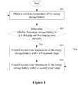
Figure 1 is a flowchart of a temperature control method for an energy storage system according to an embodiment of the present disclosure; -
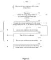
Figure 2 is a flowchart of an implementation of step S03 in the temperature control method for the energy storage system shown inFigure 1 ; -
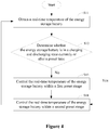
Figure 3 is a flowchart of an implementation of step S04 in the temperature control method for the energy storage system shown inFigure 1 ; -
Figure 4 is a flowchart of a temperature control method for an energy storage system according to another embodiment of the present disclosure; and -
Figure 5 is a structural schematic diagram of an energy management system according to an embodiment of the present disclosure. - Hereinafter technical solutions in embodiments of the present disclosure are described clearly and completely in conjunction with the drawings in embodiments of the present disclosure. Apparently, the described embodiments are only some rather than all of the embodiments of the present disclosure. Any other embodiments obtained based on the embodiments of the present disclosure by those skilled in the art without any creative effort fall within the scope of protection of the present disclosure.
- Reference is made to
Figure 1 , a temperature control method for an energy storage system according to an embodiment of the present disclosure is provided to reduce the power consumption of the temperature control system, thereby increasing the power generation of the entire energy storage system. - The temperature control method includes steps S01 to S04.
- In step S01, a real-time temperature of the energy storage battery is obtained.
- Specifically, the real-time temperature of the energy storage battery may be a real-time ambient temperature of the energy storage battery or a real-time battery cell temperature of the energy storage battery, which is not limited herein. Further, the real-time ambient temperature of the energy storage battery may be a temperature of a return air outlet of an air conditioner, which is not limited herein. At the same moment, the difference between the real-time ambient temperature of the energy storage battery and the real-time battery cell temperature of the energy storage battery is basically a fixed value. Therefore, whether the temperature control system uses the real-time ambient temperature of the energy storage battery as feedback to automatically perform temperature control, or the temperature control system uses the real-time battery cell temperature of the energy storage battery as feedback to automatically perform temperature control, the temperature control effect achieved by both is the same.
- In step S02, whether the energy storage battery is in a charging and discharging state currently is determined. If no, step S03 is executed; and if yes, step S04 is executed.
- In step S03, the real-time temperature of the energy storage battery is controlled within a first preset range and then step S01 is returned to.
- In step S04, the real-time temperature of the energy storage battery is controlled within a second preset range and then step S01 is returned to, where the first preset range is wider than the second preset range.
- Specifically, the energy storage system is not always in the charging and discharging state twenty four hours a day, but also occasionally enters a static state under the control of an energy management system. The energy storage system being in the charging and discharging state means that the energy storage battery being in the charging and discharging state, and the energy storage system being in the static state means that the energy storage battery being in the static state. The energy storage battery requires a stable and suitable temperature range regardless of whether it is in the charging and discharging state or in the static state, and the energy storage battery requires a wider range in the static state than in the charging and discharging state. For example, taking the ambient temperature of an energy storage battery as an example, for a certain energy storage battery, the suitable ambient temperature range in the charging and discharging state is from 18 degrees Celsius to 28 degrees Celsius, and that in the static state is from 5 degrees Celsius to 50 degrees Celsius.
- Because the narrower the temperature range required for automatic temperature control, the more frequent the air conditioning, and the higher the power consumption of the temperature control system. Therefore, if the temperature range required in the charging and discharging state is always maintained regardless of whether the energy storage battery is in the charging and discharging state or in the static state, it will bring high power consumption. In the embodiments of the present disclosure, the energy storage battery is controlled with a wider temperature range in the static state than in the charging and discharging state. For example, the above example is still referred, the energy storage battery may be controlled within the first preset range from 5 degrees Celsius to 50 degrees Celsius in the static state, and within the second preset range from 18 degrees Celsius to 28 degrees Celsius in the charging and discharging state. Therefore, the number of air-conditioning changes is significantly reduced in a whole day, and the power consumption of the temperature control system is reduced, thereby increasing the power generation of the entire energy storage system.
- In summary, in embodiments of the preset disclosure, by utilizing the characteristic that the temperature range that the energy storage battery is allowed to maintain in the static state is wider than the temperature range that the energy storage battery is allowed to maintain in the charging and discharging state, different target temperature ranges are set according to whether the energy storage battery is in the static state or the charging and discharging state. Therefore, the number of air-conditioning changes is significantly reduced in a whole day, and the power consumption of the temperature control system is reduced, thereby increasing the power generation of the entire energy storage system.
- In an embodiment of the present disclosure, step S03 may include steps S031 to S034 as shown in
Figure 2 . Correspondingly, as shown inFigure 2 , the temperature control method includes the following steps. - In step S01, a real-time temperature of an energy storage battery is obtained.
- In step S02, whether the energy storage battery is in a charging and discharging state currently is determined. If no, step S031 is executed; and if yes, step S04 is executed.
- In step S031, the real-time temperature T of the energy storage battery is compared with a first threshold T1, a second threshold T2, a third threshold T3, and a fourth threshold T4, respectively, where T1<T2<T3<T4. If T<T1, step S032 is executed; if T2≤T≤T3, step S033 is executed; and If T>T4, step S034 is executed.
- In step S032, an air conditioner is turned on to start heating and then step S01 is returned to.
- In step S033, the air conditioner is turned off and then step S01 is returned to.
- In step S034, the air conditioner is turned on to start cooling and then step S01 is returned to.
- When T1≤T<T2 or T3<T≤T4, the air conditioner maintains the current state. In the embodiment of the present disclosure, by setting two hysteresis intervals of T1∼T2 and T3∼T4, it is avoided that the air conditioner is frequently turned on and off at the critical temperature point.
- The first threshold T1 is a lower limit of the first preset range, and the fourth threshold T4 is an upper limit of the first preset range. Specifically, the above example is still referred, T1 may be set to 5 degrees Celsius, T2 may be set to 10 degrees Celsius, T3 may be set to 45 degrees Celsius, and T4 may be set to 50 degrees Celsius. When the real-time temperature of the energy storage battery is within the first preset range, there will be a shutdown time, during which the air conditioner consumes zero power.
- In step S04, the real-time temperature of the energy storage battery is controlled within a second preset range and then step S01 is returned to, where the first preset range is wider than the second preset range.
- In an embodiment of the present disclosure, based on any temperature control method of the foregoing embodiments, step S04 may include steps S041 to S043 as shown in
Figure 3 . As shown inFigure 3 , the temperature control method includes the following steps. - In step S01, the real-time temperature of an energy storage battery is obtained.
- In step S02, whether the energy storage battery is in the charging and discharging state currently is determined. If no, step S031 is executed; and if yes, step S041 is executed.
- In step S03, the real-time temperature of the energy storage battery is controlled within the first preset range and then step S01 is returned to.
- In step S041, the real-time temperature T of the energy storage battery is compared with a fifth threshold T5 and a sixth threshold T6, respectively, where T1<T2<T5<T6<T3<T4. If T<T5, step S042 is executed; and If T>T6, step S043 is executed.
- In step S042, the air conditioner is controlled to start heating and then step S01 is returned to.
- In step S043, the air conditioner is controlled to start cooling and then step S01 is returned to.
- When T5≤T≤T6, the air conditioner maintains the current state. In the embodiment of the present disclosure, by setting the hysteresis interval of T5∼T6, it is avoided that the air conditioner is frequently turned on and off at the critical temperature point. The fifth threshold T5 is a lower limit of the second preset range, and the sixth threshold T6 is an upper limit of the second preset range. Specifically, the above example is still referred, T5 may be set to 18 degrees Celsius, and T6 may be set to 28 degrees Celsius.
- Considering that there will be a certain response time in temperature adjustment of the air conditioner, in order to enable the real-time temperature of the energy storage battery to be adjusted to an optimal state when the energy storage battery starts to charge and discharge, based on any of the foregoing embodiments, the embodiment of the present disclosure further provides the following temperature control method for the energy storage system. The temperature control method includes steps S11 to S14.
- In step S11, the real-time temperature of an energy storage battery is obtained.
- In step S12, whether the energy storage battery is in the charging and discharging state currently or after a preset time is determined. If no, step S13 is executed; and if yes, step S14 is executed.
- In step S13, the real-time temperature of the energy storage battery is controlled within the first preset range and then step S11 is returned to.
- In step S14, the real-time temperature of the energy storage battery is controlled within the second preset range and then step S11 is returned to, where the first preset range is wider than the second preset range.
- It should be noted that, although the suitable ambient temperature range in the charging and discharging state in the example is from 18 degrees Celsius to 28 degrees Celsius, and the suitable ambient temperature range in the static state is from 5 degrees Celsius to 50 degrees Celsius, it does not mean that T1 must be set to 5 degrees Celsius, T4 must be set to 50 degrees Celsius, T5 must be set to 18 degrees Celsius, and T6 must be set to 26 degrees Celsius. The above assignment is just an example, and other assignments are also available, for example, T1 is set to 6 degrees Celsius, T4 is set to 49 degrees Celsius, T5 is set to 19 degrees Celsius, and T6 is set to 27 degrees Celsius. That is, the specific temperature range is not limited as long as it can be ensured that the energy storage battery is within the required temperature range in the charging and discharging state and in the static state.
- In addition, each temperature threshold is set in advance according to a type of the to-be-obtained real-time temperature of the energy storage battery. When the to-be-obtained real-time temperature of the energy storage battery is the real-time ambient temperature of the energy storage battery, each temperature threshold is set in advance for the real-time ambient temperature. When the to-be-obtained real-time temperature of the energy storage battery is the real-time battery cell temperature of the energy storage battery, each temperature threshold is set in advance for the real-time battery cell temperature of the energy storage battery.
- Corresponding to the foregoing temperature control methods, embodiments of the present disclosure further provides energy management systems.
- In an embodiment of the present disclosure, an energy management system is provided in the present disclosure as shown in
Figure 5 , and the energy management system includes an obtainingunit 100 and acontrol unit 200. - The obtaining
unit 100 is configured to obtaining a real-time temperature of an energy storage battery. - The
control unit 200 is configured to determine whether the energy storage battery is in a charging and discharging state currently. If no, the real-time temperature of the energy storage battery is controlled within a first preset range, and if yes, the real-time temperature of the energy storage battery is controlled within a second preset range, where the first preset range is wider than the second preset range. - The energy management system may be applied exclusively to one energy storage system, or may be applied to multiple energy storage systems at the same time. When applied to multiple energy storage systems at the same time, each energy storage system is provided with a local controller, the energy management system first sends monitoring instructions for an energy storage system to a corresponding local controller of said energy storage system, and then the corresponding local controller of said energy storage system monitors said energy storage system.
- Considering that there will be a certain response time in temperature adjustment of the air conditioner, in order to enable the real-time temperature of the energy storage battery to be adjusted to an optimal state when the energy storage battery starts to charge and discharge, another embodiment of the preset disclosure is provided. The energy management system is provided in the present disclosure as shown in
Figure 5 , and the energy management system includes an obtainingunit 100 and acontrol unit 200. - The obtaining
unit 100 is configured to obtaining a real-time temperature of an energy storage battery. - The
control unit 200 is configured to determine whether the energy storage battery is in a charging and discharging state currently or after a preset time. If no, the real-time temperature of the energy storage battery is controlled within a first preset range, and if yes, the real-time temperature of the energy storage battery is controlled within a second preset range, where the first preset range is wider than the second preset range. - In another embodiment of the present disclosure, based on any energy management system of the foregoing embodiments, to control the real-time temperature of the energy storage battery within the first preset range, the
control unit 200 is further configured to: compare the real-time temperature T of the energy storage battery with a first threshold T1, a second threshold T2, a third threshold T3, and a fourth threshold T4, respectively, where T1<T2<T3<T4, the first threshold T1 is a lower limit of the first preset range, and the fourth threshold T4 is an upper limit of the first preset range; turn on an air conditioner to start heating if T<T1; turn off the air conditioner if T2≤T≤T3; and turn on the air conditioner to start cooling T>T4. - In another embodiment of the present disclosure, based on any energy management system of the foregoing embodiments, to control the real-time temperature of the energy storage battery within the second preset range, the
control unit 200 is further configured to: compare the real-time temperature T of the energy storage battery with a fifth threshold T5 and a sixth threshold T6, respectively, where T5<T6, the fifth threshold T5 is a lower limit of the second preset range, and the sixth threshold T6 is an upper limit of the second preset range; control the air conditioner to start cooling if T<T6; and control the air conditioner to start heating if T>T6. - In another embodiment of the present disclosure, based on any energy management system of the foregoing embodiments, the real-time temperature of the energy storage battery is a real-time ambient temperature of the energy storage battery or a real-time battery cell temperature of the energy storage battery.
- In another embodiment of the present disclosure, based on the foregoing energy management system, the real-time ambient temperature of the energy storage battery is a temperature of a return air outlet of the air conditioner.
- It should be noted that the various embodiments in the present disclosure are described herein in a progressive manner. Each embodiment focuses on the differences from other embodiments, and the same or similar parts between the various embodiments can be referred to each other. For the systems disclosed in the embodiments, since they correspond to the methods disclosed in the embodiments, the description is relatively simple, and the relevant parts can be referred to the description of the methods.
- It should be further noted that a relationship term such as "the first" and "the second" herein is only used to distinguish one entity or operation from another entity or operation, and does not necessarily require or imply that there is an actual relationship or sequence between these entities or operations. Furthermore, terms "include", "comprise" or any other variations are intended to cover non-exclusive "include", so that a process, a method, an object or a device including a series of factors not only include the factors, but also include other factors not explicitly listed, or also include inherent factors of the process, the method, the object or the device. Without more limitation, a factor defined in a sentence "include one..." does not exclude a case that there is also another same factor in the process, the method, the object or the device including the described factor.
- Professionals shall further realize that the units and algorithm steps of each example described in combination with the embodiments disclosed herein can be implemented by electronic hardware, computer software, or a combination of both. In order to clearly illustrate the interchangeability of hardware and software, the composition and steps of each example have been generally described in accordance with the function in the above description. Whether these functions are executed by hardware or software depends on the specific application and design constraints of the technical solution. Professionals and technicians can use different methods for each specific application to implement the described functions, but such implementation shall not be considered as going beyond the scope of the present invention.
- The steps of the method or algorithm described in combination with the embodiments disclosed herein can be directly implemented by hardware, a software module executed by a processor, or a combination of the two. The software module can be placed in random access memory (RAM), internal memory, read-only memory (ROM), electrically programmable ROM, electrically erasable programmable ROM, registers, hard disks, removable disks, CD-ROMs, or any other form of storage medium known in the technical field.
- The above description of the embodiments enables those skilled in the art to implement or use the present disclosure. Various modifications to these embodiments are apparent to those skilled in the art, and the general principle defined herein may be implemented in other embodiments without deviating from the spirit or scope of the present disclosure. Therefore, the present disclosure is not limited to these embodiments described herein, but in accordance with the widest scope consistent with the principle and novel features disclosed herein.
Claims (10)
- A temperature control method for an energy storage system comprising an energy storage battery, comprising:obtaining a real-time temperature of the energy storage battery;determining whether the energy storage battery is in a charging and discharging state currently or after a preset time;controlling, in a case that the energy storage battery is in the charging and discharging state, the real-time temperature of the energy storage battery within a first preset range; andcontrolling, in a case that the energy storage battery is not in the charging and discharging state, the real-time temperature of the energy storage battery within a second preset range, wherein a lower limit of the first preset range is less than a lower limit of the second preset range, and an upper limit of the first preset range is greater than an upper limit of the second preset range.
- The method according to claim 1, wherein the controlling the real-time temperature of the energy storage battery within the first preset range comprises:comparing the real-time temperature T of the energy storage battery with a first threshold T1, a second threshold T2, a third threshold T3, and a fourth threshold T4, respectively, wherein the first threshold T1, the second threshold T2, the third threshold T3, and the fourth threshold T4 are in ascending order, the first threshold T1 is the lower limit of the first preset range, and the fourth threshold T4 is the upper limit of the first preset range;turning on an air conditioner to start heating in a case that the real-time temperature T is less that the first threshold T1;turning off the air conditioner in a case that the real-time temperature T is greater than or equal to the second threshold T2 and less than or equal to the third threshold T3; andturning on the air conditioner to start cooling in a case that the real-time temperature T is greater than the fourth threshold T4.
- The method according to claim 1, wherein the controlling the real-time temperature of the energy storage battery within the second preset range comprises:comparing the real-time temperature T of the energy storage battery with a fifth threshold T5 and a sixth threshold T6, respectively, wherein the fifth threshold T5 is less than the sixth threshold T6, the fifth threshold T5 is the lower limit of the second preset range, and the sixth threshold T6 is the upper limit of the second preset range;controlling an air conditioner to start heating in a case that the real-time temperature T is less than that the fifth threshold T5; andcontrolling the air conditioner to start heating in a case that the real-time temperature T is greater than the sixth threshold T6.
- The method according to any one of claims 1 to 3, wherein the real-time temperature of the energy storage battery is a real-time ambient temperature of the energy storage battery or a real-time battery cell temperature of the energy storage battery.
- The method according to claim 4, wherein the real-time ambient temperature of the energy storage battery is a temperature of a return air outlet of an air conditioner.
- An energy management system, comprising:an obtaining unit, configured to obtaining a real-time temperature of an energy storage battery;a control unit, configured to:determine whether the energy storage battery is in a charging and discharging state currently or after a preset time;control the real-time temperature of the energy storage battery within a first preset range in a case that the energy storage battery is in the charging and discharging state; andcontrol the real-time temperature of the energy storage battery within a second preset range in a case that the energy storage battery is in the charging and discharging state, wherein a lower limit of the first preset range is less than a lower limit of the second preset range, and an upper limit of the first preset range is greater than an upper limit of the second preset range.
- The system according to claim 6, wherein, to control the real-time temperature of the energy storage battery within the first preset range, the control unit is further configured to:compare the real-time temperature T of the energy storage battery with a first threshold T1, a second threshold T2, a third threshold T3, and a fourth threshold T4, respectively, wherein the first threshold T1, the second threshold T2, the third threshold T3, and the fourth threshold T4 are in ascending order, the first threshold T1 is the lower limit of the first preset range, and the fourth threshold T4 is the upper limit of the first preset range;turn on an air conditioner to start heating in a case that the real-time temperature T is less that the first threshold T1;turn off the air conditioner in a case that the real-time temperature T is greater than or equal to the second threshold T2 and less than or equal to the third threshold T3; andturn on the air conditioner to start cooling in a case that the real-time temperature T is greater than the fourth threshold T4.
- The system according to claim 6, wherein, to control the real-time temperature of the energy storage battery within the second preset range, the control unit is further configured to:compare the real-time temperature T of the energy storage battery with a fifth threshold T5 and a sixth threshold T6, respectively, wherein the fifth threshold T5 is less than the sixth threshold T6, the fifth threshold T5 is the lower limit of the second preset range, and the sixth threshold T6 is the upper limit of the second preset range;control the air conditioner to start heating in a case that the real-time temperature T is less than that the fifth threshold T5; andcontrol the air conditioner to start cooling in a case that the real-time temperature T is greater than the sixth threshold T6.
- The system according to any one of claims 6 to 8, wherein the real-time temperature of the energy storage battery is a real-time ambient temperature of the energy storage battery or a real-time battery cell temperature of the energy storage battery.
- The system according to claim 9, wherein the real-time ambient temperature of the energy storage battery is a temperature of a return air outlet of an air conditioner.
Applications Claiming Priority (1)
| Application Number | Priority Date | Filing Date | Title |
|---|---|---|---|
| CN202010589815.3A CN111641004A (en) | 2020-06-24 | 2020-06-24 | A kind of energy storage system temperature control method and energy management system |
Publications (3)
| Publication Number | Publication Date |
|---|---|
| EP3930078A1 true EP3930078A1 (en) | 2021-12-29 |
| EP3930078C0 EP3930078C0 (en) | 2023-12-06 |
| EP3930078B1 EP3930078B1 (en) | 2023-12-06 |
Family
ID=72332618
Family Applications (1)
| Application Number | Title | Priority Date | Filing Date |
|---|---|---|---|
| EP21181205.2A Active EP3930078B1 (en) | 2020-06-24 | 2021-06-23 | Temperature control method for energy storage system, and energy management system |
Country Status (3)
| Country | Link |
|---|---|
| US (1) | US20210408617A1 (en) |
| EP (1) | EP3930078B1 (en) |
| CN (1) | CN111641004A (en) |
Cited By (1)
| Publication number | Priority date | Publication date | Assignee | Title |
|---|---|---|---|---|
| CN114779858A (en) * | 2022-06-13 | 2022-07-22 | 深圳市帝迈生物技术有限公司 | Method, device, equipment and storage medium for starting sample analysis device |
Families Citing this family (15)
| Publication number | Priority date | Publication date | Assignee | Title |
|---|---|---|---|---|
| CN112331961B (en) * | 2020-10-30 | 2021-12-14 | 湖北亿纬动力有限公司 | Temperature control method, device and equipment of battery cell and storage medium |
| CN112531232B (en) | 2020-12-01 | 2023-03-31 | 阳光电源股份有限公司 | Energy storage system and thermal management method thereof |
| CN113097583A (en) * | 2021-03-31 | 2021-07-09 | 蜂巢能源科技(无锡)有限公司 | Temperature control method, device and equipment of cabinet type energy storage system |
| CN113097597B (en) * | 2021-04-02 | 2023-02-03 | 阳光电源股份有限公司 | Thermal management method, controller and energy storage system of energy storage system |
| CN113741592A (en) * | 2021-08-26 | 2021-12-03 | 深圳市禾望电气股份有限公司 | Control method for temperature control system of energy storage converter |
| WO2023221020A1 (en) * | 2022-05-19 | 2023-11-23 | 宁德时代新能源科技股份有限公司 | Power consumption control method and power consumption control system |
| CN115854494A (en) * | 2022-10-14 | 2023-03-28 | 国网冀北综合能源服务有限公司 | An energy-saving control method for air-conditioning of an energy storage system in planning curve mode |
| CN115549256B (en) * | 2022-10-18 | 2026-05-12 | 阳光储能技术有限公司 | Charging and discharging control method of energy storage system, energy storage system and storage medium |
| CN116130842A (en) * | 2023-03-09 | 2023-05-16 | 阳光电源股份有限公司 | Temperature control method and device of energy storage system and nonvolatile storage medium |
| CN116315301B (en) * | 2023-05-16 | 2023-08-18 | 惠州市乐亿通科技有限公司 | Energy storage system battery heating management method and device |
| CN116879788A (en) * | 2023-07-04 | 2023-10-13 | 广东鸿昊升能源科技有限公司 | Energy storage electric cabinet safety detection method, device, equipment and storage medium |
| CN117276749B (en) * | 2023-11-22 | 2024-04-16 | 江苏天合储能有限公司 | Temperature control method, device and electronic equipment for energy storage system |
| CN117393911B (en) * | 2023-12-11 | 2024-04-16 | 江苏天合储能有限公司 | Thermal management method for energy storage system, energy management system, energy storage system and medium |
| CN118248999B (en) * | 2024-05-28 | 2024-11-08 | 常州博瑞电力自动化设备有限公司 | Method and system for thermal management of net-structured energy storage cabinet |
| CN118943584A (en) * | 2024-08-08 | 2024-11-12 | 上海摩瓦新能源科技有限公司 | Thermal management method, device, system, equipment and storage medium for energy storage system |
Citations (3)
| Publication number | Priority date | Publication date | Assignee | Title |
|---|---|---|---|---|
| US5937664A (en) * | 1997-03-05 | 1999-08-17 | Toyota Jidosha Kabushiki Kaisha | Battery cooling system for vehicle |
| KR20170104763A (en) * | 2016-03-08 | 2017-09-18 | 한국전력공사 | System and method for managing temperature of battery |
| CN110137619A (en) * | 2019-04-15 | 2019-08-16 | 华为技术有限公司 | Energy storage device temprature control method and device |
Family Cites Families (46)
| Publication number | Priority date | Publication date | Assignee | Title |
|---|---|---|---|---|
| GB2176902B (en) * | 1985-06-19 | 1989-10-11 | Bl Tech Ltd | Method and apparatus for determining the state of charge of a battery |
| JP2001291532A (en) * | 2000-04-07 | 2001-10-19 | Fuji Heavy Ind Ltd | Battery temperature control device |
| JP2002027612A (en) * | 2000-07-06 | 2002-01-25 | Fuji Heavy Ind Ltd | Electric vehicle battery cooling system |
| KR100471249B1 (en) * | 2002-08-23 | 2005-03-10 | 현대자동차주식회사 | Battery temperature management method of electric vehicle |
| US20060028182A1 (en) * | 2004-07-23 | 2006-02-09 | Jihui Yang | Thermoelectric methods to control temperature of batteries |
| JP4791054B2 (en) * | 2005-03-02 | 2011-10-12 | プライムアースEvエナジー株式会社 | Temperature management device and power supply device |
| US7514904B2 (en) * | 2005-12-20 | 2009-04-07 | Caterpillar Inc. | System and method for determining battery temperature |
| US7789176B2 (en) * | 2007-04-11 | 2010-09-07 | Tesla Motors, Inc. | Electric vehicle thermal management system |
| US7671567B2 (en) * | 2007-06-15 | 2010-03-02 | Tesla Motors, Inc. | Multi-mode charging system for an electric vehicle |
| JP2009252688A (en) * | 2008-04-10 | 2009-10-29 | Toyota Motor Corp | Temperature control system of storage battery for vehicle |
| JP2010262879A (en) * | 2009-05-11 | 2010-11-18 | Kansai Electric Power Co Inc:The | Temperature adjuster, power storage device, temperature control program and temperature control method |
| US8974929B2 (en) * | 2011-06-30 | 2015-03-10 | Lg Chem, Ltd. | Heating system for a battery module and method of heating the battery module |
| US8620506B2 (en) * | 2011-12-21 | 2013-12-31 | Ford Global Technologies, Llc | Method and system for thermal management of a high voltage battery for a vehicle |
| US8907629B2 (en) * | 2012-02-28 | 2014-12-09 | Tesla Motors, Inc. | Electric vehicle battery lifetime optimization operational mode |
| US9991568B2 (en) * | 2012-03-19 | 2018-06-05 | Nissan Motor Co., Ltd. | Battery-temperature adjustment apparatus |
| US20140012447A1 (en) * | 2012-07-03 | 2014-01-09 | Magna E-Car Systems Of America, Inc. | Thermal management of vehicle battery pack during charging |
| GB2504689B (en) * | 2012-08-06 | 2015-07-29 | Jaguar Land Rover Ltd | Control of rechargeable electric battery system for a vehicle |
| KR101371740B1 (en) * | 2012-09-07 | 2014-03-12 | 기아자동차(주) | System and method for controlling temperature of battery |
| CN102848877B (en) * | 2012-09-21 | 2016-01-20 | 王建排 | The automatic air control system of electronlmobil and control method |
| US9337680B2 (en) * | 2013-03-12 | 2016-05-10 | Ford Global Technologies, Llc | Method and system for controlling an electric vehicle while charging |
| FR3005208B1 (en) * | 2013-04-30 | 2015-04-24 | Renault Sa | METHOD FOR CONTROLLING THE TEMPERATURE OF A BATTERY OF AN ELECTRIC OR HYBRID VEHICLE. |
| FR3005374B1 (en) * | 2013-05-02 | 2016-05-27 | Renault Sa | METHOD FOR CONTROLLING THE COOLING OF A BATTERY WITH ADJUSTABLE COOLING THRESHOLDS |
| JP6028756B2 (en) * | 2014-03-19 | 2016-11-16 | トヨタ自動車株式会社 | Battery temperature control device |
| CN104505480A (en) * | 2014-12-23 | 2015-04-08 | 中国北方车辆研究所 | Enclosed battery box for active heat management of electric vehicle |
| US10573940B2 (en) * | 2015-02-25 | 2020-02-25 | Ford Global Technologies, Llc | Battery thermal management system |
| US9969293B2 (en) * | 2015-03-30 | 2018-05-15 | Ford Global Technologies, Llc | Battery thermal conditioning to extend battery useful life in electrified vehicles |
| US10910680B2 (en) * | 2016-01-27 | 2021-02-02 | Ford Global Technologies, Llc | Battery thermal management system including thermoelectric device |
| CN105946604B (en) * | 2016-04-28 | 2018-08-17 | 郑州宇通客车股份有限公司 | Power battery method for heating and controlling and power battery heating control system |
| CN107591589B (en) * | 2016-07-08 | 2019-08-30 | 宁德时代新能源科技股份有限公司 | Battery cell heating temperature control method |
| CN106921003B (en) * | 2016-10-25 | 2019-09-06 | 蔚来汽车有限公司 | Intelligent control system and method for electric vehicle battery pack temperature |
| CN106785198A (en) * | 2016-12-22 | 2017-05-31 | 广州汽车集团股份有限公司 | A kind of battery cooling control method and system |
| KR101961796B1 (en) * | 2017-04-28 | 2019-03-25 | (주)쿨링크래프트 | Cooling and heating system for secondary battery |
| CN107959085B (en) * | 2017-11-13 | 2020-07-24 | 河南森源电气股份有限公司 | Temperature adjusting method and system of battery energy storage equipment |
| US11342603B2 (en) * | 2018-01-15 | 2022-05-24 | Ford Global Technologies, Llc | Thermal management of traction battery based on electric current of traction battery |
| CN108878996B (en) * | 2018-05-22 | 2021-03-23 | 宁德时代新能源科技股份有限公司 | Battery pack system, control method thereof and management equipment |
| CN109305060B (en) * | 2018-10-09 | 2020-09-25 | 威马智慧出行科技(上海)有限公司 | Battery pack thermal management system and control method thereof |
| CN109548368B (en) * | 2018-11-23 | 2021-04-30 | 南京四象新能源科技有限公司 | Energy storage cabinet and control method thereof |
| CN112706657B (en) * | 2018-12-29 | 2022-12-23 | 宁德时代新能源科技股份有限公司 | Control method, battery management module, motor controller and medium |
| US11133537B2 (en) * | 2018-12-31 | 2021-09-28 | Textron Inc. | Performing temperature control on a lithium battery of a vehicle |
| CN109888437B (en) * | 2019-04-18 | 2024-03-29 | 吉林大学 | Battery pack cooling and heating system |
| CN110534839B (en) * | 2019-08-16 | 2021-03-30 | 珠海格力电器股份有限公司 | Heat dissipation control method and device of energy storage system and terminal equipment |
| CN110600831B (en) * | 2019-09-20 | 2021-07-16 | 爱驰汽车有限公司 | Temperature control method and system for battery pack, electronic device and storage medium |
| CN110661059B (en) * | 2019-09-30 | 2021-04-13 | 恒大恒驰新能源汽车科技(广东)有限公司 | Vehicle battery thermal management method, device and system |
| CN113119795B (en) * | 2019-12-31 | 2022-10-18 | 比亚迪股份有限公司 | Battery heating method, device, equipment and computer readable storage medium |
| CN113745703B (en) * | 2020-05-29 | 2023-11-14 | 比亚迪股份有限公司 | Heating methods and devices for power batteries and vehicles |
| CN111391718B (en) * | 2020-06-04 | 2020-10-23 | 比亚迪股份有限公司 | Battery energy processing device and method and vehicle |
-
2020
- 2020-06-24 CN CN202010589815.3A patent/CN111641004A/en active Pending
-
2021
- 2021-06-21 US US17/352,448 patent/US20210408617A1/en not_active Abandoned
- 2021-06-23 EP EP21181205.2A patent/EP3930078B1/en active Active
Patent Citations (3)
| Publication number | Priority date | Publication date | Assignee | Title |
|---|---|---|---|---|
| US5937664A (en) * | 1997-03-05 | 1999-08-17 | Toyota Jidosha Kabushiki Kaisha | Battery cooling system for vehicle |
| KR20170104763A (en) * | 2016-03-08 | 2017-09-18 | 한국전력공사 | System and method for managing temperature of battery |
| CN110137619A (en) * | 2019-04-15 | 2019-08-16 | 华为技术有限公司 | Energy storage device temprature control method and device |
Cited By (2)
| Publication number | Priority date | Publication date | Assignee | Title |
|---|---|---|---|---|
| CN114779858A (en) * | 2022-06-13 | 2022-07-22 | 深圳市帝迈生物技术有限公司 | Method, device, equipment and storage medium for starting sample analysis device |
| CN114779858B (en) * | 2022-06-13 | 2022-10-28 | 深圳市帝迈生物技术有限公司 | Method, device, equipment and storage medium for starting sample analysis device |
Also Published As
| Publication number | Publication date |
|---|---|
| EP3930078C0 (en) | 2023-12-06 |
| EP3930078B1 (en) | 2023-12-06 |
| CN111641004A (en) | 2020-09-08 |
| US20210408617A1 (en) | 2021-12-30 |
Similar Documents
| Publication | Publication Date | Title |
|---|---|---|
| EP3930078B1 (en) | Temperature control method for energy storage system, and energy management system | |
| EP4009419B1 (en) | Energy storage system and thermal management method for the same | |
| CN112550086B (en) | Vehicle energy management method and device, vehicle and storage medium | |
| CN111216596A (en) | A fuel cell vehicle energy management method, device, vehicle and storage medium | |
| US9770999B2 (en) | Control method of cooling water pump of fuel cell vehicle | |
| KR20170069374A (en) | Method for controlling voltage of fuelcell in stop-mode of fuelcell vehicle | |
| EP3703179A1 (en) | Method and device for predicting service capability of battery replacement station | |
| CN108461860B (en) | Cooling control method for battery management system in electric vehicle | |
| CN111731152B (en) | Power control method, device, vehicle and storage medium | |
| JP2023514885A (en) | Charging method and power converter | |
| CN116262459A (en) | Fuel cell powertrain and method of power division and distribution therein | |
| CN115642338B (en) | A thermal management strategy optimization method and terminal | |
| KR20170122063A (en) | Method for controlling start of fuel cell vehicle | |
| CN117922309B (en) | Motor torque limiting method, device, controller and computer readable storage medium | |
| CN112821385A (en) | Control method and device of energy storage system and computer readable storage medium | |
| US11217802B2 (en) | Method and system for estimating available output of fuel cell | |
| CN116191509A (en) | Control method of optical storage system, optical storage system and storage medium | |
| CN119099438B (en) | Adaptive working condition request power control method, device and equipment | |
| US11050258B2 (en) | Battery control system | |
| CN119650964A (en) | A temperature control system and method for a lithium-ion battery energy storage system | |
| CN113942362A (en) | Heat management system and method for pure electric vehicle | |
| EP4343999A1 (en) | Electric motor overload protection method, electric motor controller, automobile and storage medium | |
| CN112993335B (en) | Calibration method of fuel cell thermal management system | |
| CN213109081U (en) | Control system of fuel cell | |
| EP4272992B1 (en) | Hybrid charging device for electric vehicle, charging system comprising the same, and charging method using the same |
Legal Events
| Date | Code | Title | Description |
|---|---|---|---|
| PUAI | Public reference made under article 153(3) epc to a published international application that has entered the european phase |
Free format text: ORIGINAL CODE: 0009012 |
|
| STAA | Information on the status of an ep patent application or granted ep patent |
Free format text: STATUS: REQUEST FOR EXAMINATION WAS MADE |
|
| 17P | Request for examination filed |
Effective date: 20210623 |
|
| AK | Designated contracting states |
Kind code of ref document: A1 Designated state(s): AL AT BE BG CH CY CZ DE DK EE ES FI FR GB GR HR HU IE IS IT LI LT LU LV MC MK MT NL NO PL PT RO RS SE SI SK SM TR |
|
| B565 | Issuance of search results under rule 164(2) epc |
Effective date: 20211108 |
|
| GRAP | Despatch of communication of intention to grant a patent |
Free format text: ORIGINAL CODE: EPIDOSNIGR1 |
|
| STAA | Information on the status of an ep patent application or granted ep patent |
Free format text: STATUS: GRANT OF PATENT IS INTENDED |
|
| INTG | Intention to grant announced |
Effective date: 20230324 |
|
| GRAJ | Information related to disapproval of communication of intention to grant by the applicant or resumption of examination proceedings by the epo deleted |
Free format text: ORIGINAL CODE: EPIDOSDIGR1 |
|
| STAA | Information on the status of an ep patent application or granted ep patent |
Free format text: STATUS: REQUEST FOR EXAMINATION WAS MADE |
|
| GRAP | Despatch of communication of intention to grant a patent |
Free format text: ORIGINAL CODE: EPIDOSNIGR1 |
|
| STAA | Information on the status of an ep patent application or granted ep patent |
Free format text: STATUS: GRANT OF PATENT IS INTENDED |
|
| INTC | Intention to grant announced (deleted) | ||
| INTG | Intention to grant announced |
Effective date: 20230807 |
|
| GRAS | Grant fee paid |
Free format text: ORIGINAL CODE: EPIDOSNIGR3 |
|
| GRAA | (expected) grant |
Free format text: ORIGINAL CODE: 0009210 |
|
| STAA | Information on the status of an ep patent application or granted ep patent |
Free format text: STATUS: THE PATENT HAS BEEN GRANTED |
|
| AK | Designated contracting states |
Kind code of ref document: B1 Designated state(s): AL AT BE BG CH CY CZ DE DK EE ES FI FR GB GR HR HU IE IS IT LI LT LU LV MC MK MT NL NO PL PT RO RS SE SI SK SM TR |
|
| REG | Reference to a national code |
Ref country code: GB Ref legal event code: FG4D |
|
| REG | Reference to a national code |
Ref country code: DE Ref legal event code: R096 Ref document number: 602021007416 Country of ref document: DE |
|
| REG | Reference to a national code |
Ref country code: CH Ref legal event code: EP |
|
| REG | Reference to a national code |
Ref country code: IE Ref legal event code: FG4D |
|
| U01 | Request for unitary effect filed |
Effective date: 20231215 |
|
| U07 | Unitary effect registered |
Designated state(s): AT BE BG DE DK EE FI FR IT LT LU LV MT NL PT SE SI Effective date: 20231221 |
|
| PG25 | Lapsed in a contracting state [announced via postgrant information from national office to epo] |
Ref country code: GR Free format text: LAPSE BECAUSE OF FAILURE TO SUBMIT A TRANSLATION OF THE DESCRIPTION OR TO PAY THE FEE WITHIN THE PRESCRIBED TIME-LIMIT Effective date: 20240307 |
|
| PG25 | Lapsed in a contracting state [announced via postgrant information from national office to epo] |
Ref country code: ES Free format text: LAPSE BECAUSE OF FAILURE TO SUBMIT A TRANSLATION OF THE DESCRIPTION OR TO PAY THE FEE WITHIN THE PRESCRIBED TIME-LIMIT Effective date: 20231206 |
|
| PG25 | Lapsed in a contracting state [announced via postgrant information from national office to epo] |
Ref country code: GR Free format text: LAPSE BECAUSE OF FAILURE TO SUBMIT A TRANSLATION OF THE DESCRIPTION OR TO PAY THE FEE WITHIN THE PRESCRIBED TIME-LIMIT Effective date: 20240307 Ref country code: ES Free format text: LAPSE BECAUSE OF FAILURE TO SUBMIT A TRANSLATION OF THE DESCRIPTION OR TO PAY THE FEE WITHIN THE PRESCRIBED TIME-LIMIT Effective date: 20231206 |
|
| PG25 | Lapsed in a contracting state [announced via postgrant information from national office to epo] |
Ref country code: RS Free format text: LAPSE BECAUSE OF FAILURE TO SUBMIT A TRANSLATION OF THE DESCRIPTION OR TO PAY THE FEE WITHIN THE PRESCRIBED TIME-LIMIT Effective date: 20231206 Ref country code: NO Free format text: LAPSE BECAUSE OF FAILURE TO SUBMIT A TRANSLATION OF THE DESCRIPTION OR TO PAY THE FEE WITHIN THE PRESCRIBED TIME-LIMIT Effective date: 20240306 Ref country code: HR Free format text: LAPSE BECAUSE OF FAILURE TO SUBMIT A TRANSLATION OF THE DESCRIPTION OR TO PAY THE FEE WITHIN THE PRESCRIBED TIME-LIMIT Effective date: 20231206 |
|
| PG25 | Lapsed in a contracting state [announced via postgrant information from national office to epo] |
Ref country code: IS Free format text: LAPSE BECAUSE OF FAILURE TO SUBMIT A TRANSLATION OF THE DESCRIPTION OR TO PAY THE FEE WITHIN THE PRESCRIBED TIME-LIMIT Effective date: 20240406 |
|
| PG25 | Lapsed in a contracting state [announced via postgrant information from national office to epo] |
Ref country code: CZ Free format text: LAPSE BECAUSE OF FAILURE TO SUBMIT A TRANSLATION OF THE DESCRIPTION OR TO PAY THE FEE WITHIN THE PRESCRIBED TIME-LIMIT Effective date: 20231206 |
|
| U20 | Renewal fee for the european patent with unitary effect paid |
Year of fee payment: 4 Effective date: 20240614 |
|
| PG25 | Lapsed in a contracting state [announced via postgrant information from national office to epo] |
Ref country code: SK Free format text: LAPSE BECAUSE OF FAILURE TO SUBMIT A TRANSLATION OF THE DESCRIPTION OR TO PAY THE FEE WITHIN THE PRESCRIBED TIME-LIMIT Effective date: 20231206 |
|
| PG25 | Lapsed in a contracting state [announced via postgrant information from national office to epo] |
Ref country code: SM Free format text: LAPSE BECAUSE OF FAILURE TO SUBMIT A TRANSLATION OF THE DESCRIPTION OR TO PAY THE FEE WITHIN THE PRESCRIBED TIME-LIMIT Effective date: 20231206 Ref country code: SK Free format text: LAPSE BECAUSE OF FAILURE TO SUBMIT A TRANSLATION OF THE DESCRIPTION OR TO PAY THE FEE WITHIN THE PRESCRIBED TIME-LIMIT Effective date: 20231206 Ref country code: RO Free format text: LAPSE BECAUSE OF FAILURE TO SUBMIT A TRANSLATION OF THE DESCRIPTION OR TO PAY THE FEE WITHIN THE PRESCRIBED TIME-LIMIT Effective date: 20231206 Ref country code: IS Free format text: LAPSE BECAUSE OF FAILURE TO SUBMIT A TRANSLATION OF THE DESCRIPTION OR TO PAY THE FEE WITHIN THE PRESCRIBED TIME-LIMIT Effective date: 20240406 Ref country code: CZ Free format text: LAPSE BECAUSE OF FAILURE TO SUBMIT A TRANSLATION OF THE DESCRIPTION OR TO PAY THE FEE WITHIN THE PRESCRIBED TIME-LIMIT Effective date: 20231206 |
|
| PG25 | Lapsed in a contracting state [announced via postgrant information from national office to epo] |
Ref country code: PL Free format text: LAPSE BECAUSE OF FAILURE TO SUBMIT A TRANSLATION OF THE DESCRIPTION OR TO PAY THE FEE WITHIN THE PRESCRIBED TIME-LIMIT Effective date: 20231206 |
|
| PG25 | Lapsed in a contracting state [announced via postgrant information from national office to epo] |
Ref country code: PL Free format text: LAPSE BECAUSE OF FAILURE TO SUBMIT A TRANSLATION OF THE DESCRIPTION OR TO PAY THE FEE WITHIN THE PRESCRIBED TIME-LIMIT Effective date: 20231206 |
|
| REG | Reference to a national code |
Ref country code: DE Ref legal event code: R097 Ref document number: 602021007416 Country of ref document: DE |
|
| PLBE | No opposition filed within time limit |
Free format text: ORIGINAL CODE: 0009261 |
|
| STAA | Information on the status of an ep patent application or granted ep patent |
Free format text: STATUS: NO OPPOSITION FILED WITHIN TIME LIMIT |
|
| 26N | No opposition filed |
Effective date: 20240909 |
|
| PG25 | Lapsed in a contracting state [announced via postgrant information from national office to epo] |
Ref country code: MC Free format text: LAPSE BECAUSE OF FAILURE TO SUBMIT A TRANSLATION OF THE DESCRIPTION OR TO PAY THE FEE WITHIN THE PRESCRIBED TIME-LIMIT Effective date: 20231206 |
|
| REG | Reference to a national code |
Ref country code: CH Ref legal event code: PL |
|
| PG25 | Lapsed in a contracting state [announced via postgrant information from national office to epo] |
Ref country code: IE Free format text: LAPSE BECAUSE OF NON-PAYMENT OF DUE FEES Effective date: 20240623 |
|
| PG25 | Lapsed in a contracting state [announced via postgrant information from national office to epo] |
Ref country code: CH Free format text: LAPSE BECAUSE OF NON-PAYMENT OF DUE FEES Effective date: 20240630 |
|
| U20 | Renewal fee for the european patent with unitary effect paid |
Year of fee payment: 5 Effective date: 20250612 |
|
| PG25 | Lapsed in a contracting state [announced via postgrant information from national office to epo] |
Ref country code: CY Free format text: LAPSE BECAUSE OF FAILURE TO SUBMIT A TRANSLATION OF THE DESCRIPTION OR TO PAY THE FEE WITHIN THE PRESCRIBED TIME-LIMIT; INVALID AB INITIO Effective date: 20210623 |
|
| GBPC | Gb: european patent ceased through non-payment of renewal fee |
Effective date: 20250623 |
|
| PG25 | Lapsed in a contracting state [announced via postgrant information from national office to epo] |
Ref country code: HU Free format text: LAPSE BECAUSE OF FAILURE TO SUBMIT A TRANSLATION OF THE DESCRIPTION OR TO PAY THE FEE WITHIN THE PRESCRIBED TIME-LIMIT; INVALID AB INITIO Effective date: 20210623 |
|
| PG25 | Lapsed in a contracting state [announced via postgrant information from national office to epo] |
Ref country code: GB Free format text: LAPSE BECAUSE OF NON-PAYMENT OF DUE FEES Effective date: 20250623 |