EP3930076A1 - Battery, drive device, and vehicle - Google Patents
Battery, drive device, and vehicle Download PDFInfo
- Publication number
- EP3930076A1 EP3930076A1 EP20866462.3A EP20866462A EP3930076A1 EP 3930076 A1 EP3930076 A1 EP 3930076A1 EP 20866462 A EP20866462 A EP 20866462A EP 3930076 A1 EP3930076 A1 EP 3930076A1
- Authority
- EP
- European Patent Office
- Prior art keywords
- box body
- sealing gasket
- protruding portion
- battery
- wall
- Prior art date
- Legal status (The legal status is an assumption and is not a legal conclusion. Google has not performed a legal analysis and makes no representation as to the accuracy of the status listed.)
- Granted
Links
Images




Classifications
-
- B—PERFORMING OPERATIONS; TRANSPORTING
- B60—VEHICLES IN GENERAL
- B60K—ARRANGEMENT OR MOUNTING OF PROPULSION UNITS OR OF TRANSMISSIONS IN VEHICLES; ARRANGEMENT OR MOUNTING OF PLURAL DIVERSE PRIME-MOVERS IN VEHICLES; AUXILIARY DRIVES FOR VEHICLES; INSTRUMENTATION OR DASHBOARDS FOR VEHICLES; ARRANGEMENTS IN CONNECTION WITH COOLING, AIR INTAKE, GAS EXHAUST OR FUEL SUPPLY OF PROPULSION UNITS IN VEHICLES
- B60K1/00—Arrangement or mounting of electrical propulsion units
- B60K1/04—Arrangement or mounting of electrical propulsion units of the electric storage means for propulsion
-
- H—ELECTRICITY
- H01—ELECTRIC ELEMENTS
- H01M—PROCESSES OR MEANS, e.g. BATTERIES, FOR THE DIRECT CONVERSION OF CHEMICAL ENERGY INTO ELECTRICAL ENERGY
- H01M50/00—Constructional details or processes of manufacture of the non-active parts of electrochemical cells other than fuel cells, e.g. hybrid cells
- H01M50/20—Mountings; Secondary casings or frames; Racks, modules or packs; Suspension devices; Shock absorbers; Transport or carrying devices; Holders
- H01M50/204—Racks, modules or packs for multiple batteries or multiple cells
-
- B—PERFORMING OPERATIONS; TRANSPORTING
- B60—VEHICLES IN GENERAL
- B60L—PROPULSION OF ELECTRICALLY-PROPELLED VEHICLES; SUPPLYING ELECTRIC POWER FOR AUXILIARY EQUIPMENT OF ELECTRICALLY-PROPELLED VEHICLES; ELECTRODYNAMIC BRAKE SYSTEMS FOR VEHICLES IN GENERAL; MAGNETIC SUSPENSION OR LEVITATION FOR VEHICLES; MONITORING OPERATING VARIABLES OF ELECTRICALLY-PROPELLED VEHICLES; ELECTRIC SAFETY DEVICES FOR ELECTRICALLY-PROPELLED VEHICLES
- B60L50/00—Electric propulsion with power supplied within the vehicle
- B60L50/50—Electric propulsion with power supplied within the vehicle using propulsion power supplied by batteries or fuel cells
- B60L50/60—Electric propulsion with power supplied within the vehicle using propulsion power supplied by batteries or fuel cells using power supplied by batteries
- B60L50/64—Constructional details of batteries specially adapted for electric vehicles
-
- H—ELECTRICITY
- H01—ELECTRIC ELEMENTS
- H01M—PROCESSES OR MEANS, e.g. BATTERIES, FOR THE DIRECT CONVERSION OF CHEMICAL ENERGY INTO ELECTRICAL ENERGY
- H01M50/00—Constructional details or processes of manufacture of the non-active parts of electrochemical cells other than fuel cells, e.g. hybrid cells
- H01M50/20—Mountings; Secondary casings or frames; Racks, modules or packs; Suspension devices; Shock absorbers; Transport or carrying devices; Holders
- H01M50/204—Racks, modules or packs for multiple batteries or multiple cells
- H01M50/207—Racks, modules or packs for multiple batteries or multiple cells characterised by their shape
- H01M50/209—Racks, modules or packs for multiple batteries or multiple cells characterised by their shape adapted for prismatic or rectangular cells
-
- H—ELECTRICITY
- H01—ELECTRIC ELEMENTS
- H01M—PROCESSES OR MEANS, e.g. BATTERIES, FOR THE DIRECT CONVERSION OF CHEMICAL ENERGY INTO ELECTRICAL ENERGY
- H01M50/00—Constructional details or processes of manufacture of the non-active parts of electrochemical cells other than fuel cells, e.g. hybrid cells
- H01M50/20—Mountings; Secondary casings or frames; Racks, modules or packs; Suspension devices; Shock absorbers; Transport or carrying devices; Holders
- H01M50/244—Secondary casings; Racks; Suspension devices; Carrying devices; Holders characterised by their mounting method
-
- H—ELECTRICITY
- H01—ELECTRIC ELEMENTS
- H01M—PROCESSES OR MEANS, e.g. BATTERIES, FOR THE DIRECT CONVERSION OF CHEMICAL ENERGY INTO ELECTRICAL ENERGY
- H01M50/00—Constructional details or processes of manufacture of the non-active parts of electrochemical cells other than fuel cells, e.g. hybrid cells
- H01M50/20—Mountings; Secondary casings or frames; Racks, modules or packs; Suspension devices; Shock absorbers; Transport or carrying devices; Holders
- H01M50/249—Mountings; Secondary casings or frames; Racks, modules or packs; Suspension devices; Shock absorbers; Transport or carrying devices; Holders specially adapted for aircraft or vehicles, e.g. cars or trains
-
- H—ELECTRICITY
- H01—ELECTRIC ELEMENTS
- H01M—PROCESSES OR MEANS, e.g. BATTERIES, FOR THE DIRECT CONVERSION OF CHEMICAL ENERGY INTO ELECTRICAL ENERGY
- H01M50/00—Constructional details or processes of manufacture of the non-active parts of electrochemical cells other than fuel cells, e.g. hybrid cells
- H01M50/20—Mountings; Secondary casings or frames; Racks, modules or packs; Suspension devices; Shock absorbers; Transport or carrying devices; Holders
- H01M50/258—Modular batteries; Casings provided with means for assembling
- H01M50/26—Assemblies sealed to each other in a non-detachable manner
-
- H—ELECTRICITY
- H01—ELECTRIC ELEMENTS
- H01M—PROCESSES OR MEANS, e.g. BATTERIES, FOR THE DIRECT CONVERSION OF CHEMICAL ENERGY INTO ELECTRICAL ENERGY
- H01M50/00—Constructional details or processes of manufacture of the non-active parts of electrochemical cells other than fuel cells, e.g. hybrid cells
- H01M50/20—Mountings; Secondary casings or frames; Racks, modules or packs; Suspension devices; Shock absorbers; Transport or carrying devices; Holders
- H01M50/262—Mountings; Secondary casings or frames; Racks, modules or packs; Suspension devices; Shock absorbers; Transport or carrying devices; Holders with fastening means, e.g. locks
- H01M50/264—Mountings; Secondary casings or frames; Racks, modules or packs; Suspension devices; Shock absorbers; Transport or carrying devices; Holders with fastening means, e.g. locks for cells or batteries, e.g. straps, tie rods or peripheral frames
-
- B—PERFORMING OPERATIONS; TRANSPORTING
- B60—VEHICLES IN GENERAL
- B60K—ARRANGEMENT OR MOUNTING OF PROPULSION UNITS OR OF TRANSMISSIONS IN VEHICLES; ARRANGEMENT OR MOUNTING OF PLURAL DIVERSE PRIME-MOVERS IN VEHICLES; AUXILIARY DRIVES FOR VEHICLES; INSTRUMENTATION OR DASHBOARDS FOR VEHICLES; ARRANGEMENTS IN CONNECTION WITH COOLING, AIR INTAKE, GAS EXHAUST OR FUEL SUPPLY OF PROPULSION UNITS IN VEHICLES
- B60K1/00—Arrangement or mounting of electrical propulsion units
- B60K1/04—Arrangement or mounting of electrical propulsion units of the electric storage means for propulsion
- B60K2001/0405—Arrangement or mounting of electrical propulsion units of the electric storage means for propulsion characterised by their position
- B60K2001/0438—Arrangement under the floor
-
- H—ELECTRICITY
- H01—ELECTRIC ELEMENTS
- H01M—PROCESSES OR MEANS, e.g. BATTERIES, FOR THE DIRECT CONVERSION OF CHEMICAL ENERGY INTO ELECTRICAL ENERGY
- H01M2220/00—Batteries for particular applications
- H01M2220/20—Batteries in motive systems, e.g. vehicle, ship, plane
-
- Y—GENERAL TAGGING OF NEW TECHNOLOGICAL DEVELOPMENTS; GENERAL TAGGING OF CROSS-SECTIONAL TECHNOLOGIES SPANNING OVER SEVERAL SECTIONS OF THE IPC; TECHNICAL SUBJECTS COVERED BY FORMER USPC CROSS-REFERENCE ART COLLECTIONS [XRACs] AND DIGESTS
- Y02—TECHNOLOGIES OR APPLICATIONS FOR MITIGATION OR ADAPTATION AGAINST CLIMATE CHANGE
- Y02E—REDUCTION OF GREENHOUSE GAS [GHG] EMISSIONS, RELATED TO ENERGY GENERATION, TRANSMISSION OR DISTRIBUTION
- Y02E60/00—Enabling technologies; Technologies with a potential or indirect contribution to GHG emissions mitigation
- Y02E60/10—Energy storage using batteries
-
- Y—GENERAL TAGGING OF NEW TECHNOLOGICAL DEVELOPMENTS; GENERAL TAGGING OF CROSS-SECTIONAL TECHNOLOGIES SPANNING OVER SEVERAL SECTIONS OF THE IPC; TECHNICAL SUBJECTS COVERED BY FORMER USPC CROSS-REFERENCE ART COLLECTIONS [XRACs] AND DIGESTS
- Y02—TECHNOLOGIES OR APPLICATIONS FOR MITIGATION OR ADAPTATION AGAINST CLIMATE CHANGE
- Y02T—CLIMATE CHANGE MITIGATION TECHNOLOGIES RELATED TO TRANSPORTATION
- Y02T10/00—Road transport of goods or passengers
- Y02T10/60—Other road transportation technologies with climate change mitigation effect
- Y02T10/70—Energy storage systems for electromobility, e.g. batteries
Definitions
- a battery pack includes a first box body and a second box body that are connected to form a cavity for accommodating a battery unit.
- a sealing gasket is arranged between the first box body and the second box body.
- the sealing gasket is at risk of displacement, reducing airtightness of the cavity.
- first protruding portions 3 may be arranged all on the first box body 1, or all on the second box body 2, or part of them on the first box body 1 and the rest on the second box body 2.
- first protruding portions 3 located at the two ends of the battery pack in the length direction X may all be arranged on the first box body 1
- first protruding portions 3 located at the two ends of the battery pack in the width direction Y may all be arranged on the second box body 2.
- the battery pack may alternatively be referred to as a battery.
Landscapes
- Engineering & Computer Science (AREA)
- Chemical & Material Sciences (AREA)
- Chemical Kinetics & Catalysis (AREA)
- Electrochemistry (AREA)
- General Chemical & Material Sciences (AREA)
- Transportation (AREA)
- Mechanical Engineering (AREA)
- Sustainable Development (AREA)
- Sustainable Energy (AREA)
- Power Engineering (AREA)
- Life Sciences & Earth Sciences (AREA)
- Combustion & Propulsion (AREA)
- Aviation & Aerospace Engineering (AREA)
- Battery Mounting, Suspending (AREA)
Abstract
Description
- This application claims priority to
Chinese Patent Application No. 201921540884.4, filed with the China National Intellectual Property Administration on September 17, 2019 - This application relates to the technical field of energy storage devices, and in particular, to a battery, a driving apparatus, and a vehicle.
- A battery pack includes a first box body and a second box body that are connected to form a cavity for accommodating a battery unit. In addition, to make the cavity sealed, a sealing gasket is arranged between the first box body and the second box body. However, when the battery pack vibrates during operation, the sealing gasket is at risk of displacement, reducing airtightness of the cavity.
- This application provides a battery, a driving apparatus, and a vehicle, where the battery has a highly airtight cavity.
- A first aspect of this application provides a battery, including:
- a first box body;
- a second box body connected to the first box body;
- a battery unit accommodated inside the first box body and the second box body; and
- a sealing gasket located between the first box body and the second box body so that the first box body and the second box body are hermetically connected;
- where the first box body and/or the second box body is provided with a first protruding portion, a side wall of the sealing gasket is provided with a notch portion, and the notch portion runs through the sealing gasket along a thickness direction of the sealing gasket, and the first protruding portion extends into the notch portion so that the first protruding portion fits with the notch portion.
- In a possible design, the sealing gasket includes a second thickness after being compressed; and
a protrusion height of the first protruding portion is equal to the second thickness. - In a possible design, the first protruding portion is a cylindrical structure; and
the notch portion includes a first side wall, where the first side wall is arc-shaped, and a side wall of the first protruding portion abuts against the first side wall. - In a possible design, in a length direction of the battery, two ends of the second box body are both provided with first protruding portions, and two ends of the sealing gasket are both provided with notch portions; and/or
in a width direction of the battery, two ends of the second box body are both provided with first protruding portions, and two ends of the sealing gasket are both provided with notch portions. - In a possible design, the battery further includes a connecting piece;
- the first protruding portion is provided with a first mounting hole, the first box body is provided with a second mounting hole, and the second box body is provided with a third mounting hole; and
- the connecting piece runs through the second mounting hole, the first mounting hole, and the third mounting hole to fasten the first box body to the second box body.
- In a possible design, the second box body is located below the first box body;
- the first box body includes a first body portion and a first connecting portion, and the first connecting portion is connected to a periphery of the first body portion;
- the second box body comprises a second body portion and a second connecting portion, and the second connecting portion is connected to a periphery of the second body portion;
- the first protruding portion is arranged on the second connecting portion; and
- the sealing gasket is arranged between the first connecting portion and the second connecting portion, and the sealing gasket is connected to the first connecting portion and the second connecting portion.
- In a possible design, the sealing gasket includes multiple sealing strips, and the sealing strips are connected to form an annular structure;
- the sealing strip includes an inner wall and a first outer wall that are disposed opposite each other, and the inner wall is located at a side of the first outer wall closer to the battery units; and
- the notch portion is arranged in the first outer wall.
- In a possible design, a distance between the first outer wall and the inner wall is greater than 7mm.
- In a possible design, the first connecting portion includes a second protruding portion and a recessed portion, and the second protruding portion and the recessed portion are joined and arranged alternately;
- the second protruding portion protrudes away from the first protruding portion, and the recessed portion is recessed towards the first protruding portion; and
- the second protruding portion is arranged opposite the first protruding portion.
- In a possible design, the recessed portion includes a second side wall; and
the second side wall is located at a side of the first outer wall away from the battery units. - A second aspect of this application further provides a driving apparatus including the foregoing battery.
- A third aspect of this application further provides a vehicle including the foregoing battery.
- In the battery, driving apparatus and vehicle described above, the sealing gasket is provided with the notch portion that fits with the first box body and/or the second box body. As the first protruding portion and the notch portion fit with each other, the first box body and/or the second box body can limit displacement of the sealing gasket, making the sealing gasket perform better in sealing the cavity. In addition, the sealing gasket with the notch portion not only ensures the sealing performance, but also makes the sealing gasket smaller in size, thereby reducing costs and weight of a battery pack, and improving energy density.
- It should be understood that the foregoing general description and the following detailed description are only exemplary and are not intended to limit this application.
-
-
FIG. 1 is an exploded view of a battery pack according to a specific embodiment of this application; -
FIG. 2 is a schematic structural diagram ofFIG. 1 without a first box body and a connecting piece; -
FIG. 3 is a local enlarged view of part I inFIG. 2 ; -
FIG. 4 is a schematic structural diagram of a second box body inFIG. 2 fitting with a sealing gasket; -
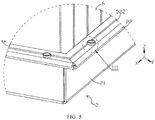
FIG. 5 is a local enlarged view of part II inFIG. 4 ; -
FIG. 6 is a local enlarged view of part III inFIG. 5 ; -
FIG. 7 is a schematic structural diagram of the part inFIG. 6 without a first protruding portion; -
FIG. 8 is a schematic structural diagram of the sealing gasket inFIG. 1 ; -
FIG. 9 is a local enlarged view of part IV inFIG. 8 ; -
FIG. 10 is a schematic structural diagram of the first box body inFIG. 1 ; -
FIG. 11 is a local enlarged view of part V inFIG. 10 ; -
FIG. 12 is a side view ofFIG. 10 ; -
FIG. 13 is a cross-sectional view of the battery pack inFIG. 1 ; and -
FIG. 14 is a local enlarged view of part VI inFIG. 13 . - Reference signs are described as follows:
- 1. first box body;
- 11. first body portion;
- 12. first connecting portion;
- 121. second mounting hole;
- 122. recessed portion;
- 122a. second side wall;
- 123. second protruding portion;
- 124. third outer wall;
- 2. second box body;
- 21. second body portion;
- 22. second connecting portion;
- 221. third mounting hole;
- 222. second outer wall;
- 3. first protruding portion;
31. first mounting hole; - 4. connecting piece;
- 5. sealing gasket;
- 51. notch portion;
511. first side wall;
- 51. notch portion;
- 52. sealing strip;
- 521. inner wall;
- 522. first outer wall;
- 6. battery unit;
- 7. cavity; and
- t1. first thickness, t2. second thickness, and h. protrusion height.
- The accompanying drawings herein are incorporated into this specification and form a part of this specification, which illustrate the embodiments conforming to this application, and are intended to explain the principles of this application together with the specification.
- To help better understand the technical solutions of this application, the following describes the embodiments of this application with reference to the accompanying drawings.
- Apparently, the described embodiments are merely some but not all of the embodiments of this application. All other embodiments obtained by a person of ordinary skill in the art based on the embodiments of this application without creative efforts shall fall within the protection scope of this application.
- The terms used in the embodiments of this application are merely intended to describe specific embodiments, but not intended to limit this application. The terms "a/an", "the" and "this" of singular forms used in the embodiments and the appended claims of this application are also intended to include plural forms, unless otherwise specified in the context clearly.
- It should be understood that in this specification, the term "and/or" is only an associative relationship for describing associated objects, indicating that three relationships may exist. For example, A and/or B may indicate three cases: only A; both A and B; and only B. In addition, a character "/" in this specification generally indicates an "or" relationship between contextually associated objects.
- It should be noted that the directional terms such as "above", "under", "left", and "right" described in the embodiments of this application are described as seen from the angles shown in the accompanying drawings, and should not be understood as limitations to the embodiments of this application. In addition, in the context, it should be further understood that when an element is referred to as being "above" or "under" another element, the element can not only be directly connected "above" or "under" the another element, but also be indirectly connected "above" or "under" the another element through an intermediate element.
- In a specific embodiment, this application provides a battery pack that is used for a vehicle. The vehicle, which may be an electric vehicle, includes a vehicle body and a driving apparatus. The driving apparatus includes a battery pack and is configured to drive the vehicle body to move along a road. That is, the battery pack provides driving force for the vehicle. As shown in
FIG. 1 andFIG. 13 , the battery pack includes a box body and multiple battery units 6, where the box body includes acavity 7, and the multiple battery units 6 are stacked in thecavity 7. The box body includes afirst box body 1 and asecond box body 2, and thefirst box body 1 and thesecond box body 2 are connected to form thecavity 7. In a possible design, the box body may be made of aluminum, lithium-aluminum alloy, or other metal materials. The battery unit 6 is a chargeable secondary battery and includes electrode terminals. Electrode terminals of the multiple battery units 6 may be connected electrically and specifically in series, parallel, or both series and parallel. - In addition, the battery pack further includes a sealing
gasket 5, where the sealinggasket 5 is located between thefirst box body 1 and thesecond box body 2, and is connected to thefirst box body 1 and thesecond box body 2, thereby making thecavity 7 better sealed with the sealinggasket 5, reducing the risk of external dust, liquid, and other foreign substances entering thecavity 7, and improving safety and service life of the battery unit 6. In a specific embodiment, thefirst box body 1 and thesecond box body 2 are disposed along a height direction Z and connected. That is, thefirst box body 1 is an upper box body, and thesecond box body 2 is a lower box body. Certainly, thefirst box body 1 and thesecond box body 2 may alternatively be disposed along a length direction X or a width direction Y and connected. Relative locations of thefirst box body 1 and thesecond box body 2 are not limited in this embodiment of this application. - Specifically, as shown in
FIG. 3 andFIG. 5 , thefirst box body 1 and/or thesecond box body 2 is provided with a first protruding portion 3, a side wall of the sealinggasket 5 is provided with anotch portion 51, and thenotch portion 51 runs through the sealinggasket 5 along a thickness direction of the sealinggasket 5, and the first protruding portion 3 extends into thenotch portion 51 with at least part of the first protruding portion 3 inside thenotch portion 51, so that the first protruding portion 3 fits with thenotch portion 51. In the battery pack provided in the embodiment of this application, the sealinggasket 5 is provided with thenotch portion 51 that fits with the first protruding portion 3 of thefirst box body 1 and/or thesecond box body 2, making a side wall of the first protruding portion 3 abut against a side wall of thenotch portion 51. Therefore, when the battery pack vibrates, the first protruding portion 3 and thenotch portion 51 fit with each other so that thefirst box body 1 and/or thesecond box body 2 limits displacement of the sealinggasket 5, making the sealinggasket 5 perform better in sealing thecavity 7. - As shown in
FIG. 9 , the side wall of the sealinggasket 5 includes aninner wall 521 and a firstouter wall 522, that is, thenotch portion 51 may be arranged in theinner wall 521, or in the firstouter wall 522, provided that the sealinggasket 5 can be prevented from being displaced by the first protruding portion 3 and thenotch portion 51. In an embodiment of this application, thenotch portion 51 may be arranged in the firstouter wall 522. - Certainly, in order to reduce the risk of displacement of the sealing
gasket 5 under vibration, the sealinggasket 5 may alternatively be provided with a through hole that fits with the first protruding portion 3. The through hole runs through the sealinggasket 5 along the thickness direction of the sealinggasket 5, and the first protruding portion 3 extends into the sealinggasket 5 and fits with the through hole, which can also limit displacement of the sealinggasket 5. However, the though hole means a closed side wall, and to fit with the first protruding portion 3, the through hole has to surround the first protruding portion 3, while thenotch portion 51 means an open side wall, and to fit with the first protruding portion 3, thenotch portion 51 does not have to surround the first protruding portion 3. Therefore, for example, for a circular through hole and an arc-shaped protruding portion that have a same diameter, the sealinggasket 5 with the circular through hole is larger in size than the sealinggasket 5 with the arc-shaped protrudingportion 51. - Based on this, compared with the sealing
gasket 5 with a through hole, the sealinggasket 5 with anotch portion 51 not only ensures the sealing performance, but also makes the sealinggasket 5 smaller in size, thereby reducing costs and weight of the battery pack, and improving energy density. - Specifically, in order to further reduce the risk of displacement of the sealing
gasket 5, the battery pack includes multiple first protruding portions 3, where in the length direction X of the battery pack, two ends of the box body are both provided with first protruding portions 3, and two ends of the sealinggasket 5 are both provided withnotch portions 51. The first protruding portions 3 fit with thecorresponding notch portions 51, limiting displacement of the sealinggasket 5 in the length direction X of the battery pack; and/or in the width direction Y of the battery pack, two ends of the box body are both provided with first protruding portions 3, and two ends of the sealinggasket 5 are both provided withnotch portions 51. The first protruding portions 3 fit with thecorresponding notch portions 51, limiting displacement of the sealinggasket 5 in the width direction Y of the battery pack. - More specifically, the first protruding portions 3 may be arranged all on the
first box body 1, or all on thesecond box body 2, or part of them on thefirst box body 1 and the rest on thesecond box body 2. For example, first protruding portions 3 located at the two ends of the battery pack in the length direction X may all be arranged on thefirst box body 1, and first protruding portions 3 located at the two ends of the battery pack in the width direction Y may all be arranged on thesecond box body 2. - In an embodiment in
FIG. 2 , the first protruding portions 3 of the box body are all arranged on thesecond box body 2. In this case, it is only necessary to process first protruding portions 3 on thesecond box body 2 without changing structure of thefirst box body 1, thereby reducing processing procedures. - In a possible design, as shown in
FIG. 9 , before thefirst box body 1 and thesecond box body 2 are fixedly connected, the sealinggasket 5 is not compressed and has a first thickness t1. As shown inFIG. 6 , after thefirst box body 1 and thesecond box body 2 are fixedly connected, they compress the sealinggasket 5, and the sealinggasket 5 includes a second thickness t2, where t2<t1. A difference between t1 and t2 is a compression amount of the sealinggasket 5 after thefirst box body 1 and thesecond box body 2 are fixedly connected. When the compression amount is excessively small, the sealing between thefirst box body 1 and thesecond box body 2 is poor, while when the compression amount is excessively large, the sealinggasket 5 will fail due to over compression, worsening the sealing between thefirst box body 1 and thesecond box body 2. Therefore, in order to ensure the sealing between thefirst box body 1 and thesecond box body 2, the compression amount of the sealinggasket 5 needs to be controlled in a reasonable range. - In the embodiment, after the
first box body 1 and thesecond box body 2 are fixedly connected, a preset distance is present between thefirst box body 1 and thesecond box body 2 due to presence of the first protruding portion 3, and the preset distance is equal to a protrusion height h of the first protruding portion 3. After the sealinggasket 5 is compressed, its second thickness t2 is equal to the protrusion height h of the first protruding portion 3, and when the protrusion height h changes, the second thickness t2 changes accordingly. Therefore, in the embodiment, the compression amount of the sealinggasket 5 is controlled in a reasonable range by controlling the protrusion height h of the first protruding portion 3, thereby ensuring the sealing between thefirst box body 1 and thesecond box body 2. - In a specific embodiment, as shown in the drawings, the first protruding portion 3 is a cylindrical structure. Correspondingly, the
notch portion 51 includes afirst side wall 511, where thefirst side wall 511 is arc-shaped, and the side wall of the first protruding portion 3 abuts against thefirst side wall 511. - Further, the arc-shaped
first side wall 511 of thenotch portion 51 allows thefirst side wall 511 to totally abut against the side wall of the first protruding portion 3, thereby improving reliability of the fitting between the first protruding portion 3 and thenotch portion 51. The central angle of the arc-shapednotch portion 51 is less than or equal to 180°, which means that an opening of thenotch portion 51 is relatively large, making it convenient for the first protruding portion 3 to abut against thefirst notch portion 51, and further reducing the area of the sealinggasket 5. - In the foregoing embodiments, as shown in
FIG. 1 , the battery pack further includes a connecting piece 4, where the connecting piece 4 is configured to connect thefirst box body 1 and thesecond box body 2. Specifically, as shown inFIG. 6 ,FIG. 7 , andFIG. 11 , the first protruding portion 3 is provided with a first mountinghole 31, thefirst box body 1 is provided with asecond mounting hole 121, and thesecond box body 2 is provided with athird mounting hole 221. The first mountinghole 31, thesecond mounting hole 121, and the third mountinghole 221 are communicated, and the connecting piece 4 runs through the first mountinghole 31, thesecond mounting hole 121, and the third mountinghole 221, and is connected to all the three mounting holes, so as to fasten thefirst box body 1 and thesecond box body 2 with the connecting piece 4 and compress the sealinggasket 5. - In the embodiment, the first protruding portion 3 not only functions to limit the position of the sealing
gasket 5 but also plays a role in connecting thefirst box body 1 and thesecond box body 2. The first protruding portion 3 can increase a fitting length of the connecting piece 4 with thesecond box body 2, thereby improving reliability of the connection between the connecting piece 4 and thesecond box body 2. - In the embodiment, in a case that a distance between adjacent mounting holes is excessively large, the connection between the
first box body 1 and thesecond box body 2 is less reliable, and the sealinggasket 5 has a low sealing performance. Therefore, the distance between adjacent first mounting holes 31 (or adjacent second mountingholes 121, or adjacent third mounting holes 221) is 60mm to 120mm. - In a specific embodiment, the first mounting
hole 31, thesecond mounting hole 121, and the third mountinghole 221 may all be threaded holes, and the connecting piece 4 may be a bolt. - In a possible design, as shown in
FIG. 10 to FIG. 12 , thefirst box body 1 includes afirst body portion 11 and a first connectingportion 12, where the first connectingportion 12 is connected to a periphery of thefirst body portion 11 and extends outward from thefirst body portion 11. Similarly, as shown inFIG. 3 andFIG. 5 , thesecond box body 2 includes asecond body portion 21 and a second connectingportion 22, where the second connectingportion 22 is connected to a periphery of thesecond body portion 21 and extends outward from thesecond body portion 21. Thefirst box body 1 and thesecond box body 2 are fixedly connected through the first connectingportion 12 and the second connectingportion 22. After they are connected, thefirst body portion 11 and thesecond body portion 21 form thecavity 7. - Specifically, the first protruding portion 3 is arranged on the second connecting
portion 22, thesecond mounting hole 121 is arranged on the first connectingportion 12, the third mountinghole 221 is arranged on the second connectingportion 22, the sealinggasket 5 is arranged between the first connectingportion 12 and the second connectingportion 22, and the sealinggasket 5 is connected to the first connectingportion 12 and the second connectingportion 22. - Specifically, as shown in
FIG. 8 , the sealinggasket 5 includes multiple sealing strips 52. The sealing strips 52 are connected to form an annular structure, and the sealing strips 52 are all located between the first connectingportion 12 and the second connectingportion 22. As shown inFIG. 9 , the sealingstrip 52 includes aninner wall 521 and a firstouter wall 522 that are disposed opposite each other, and theinner wall 521 is located at a side of the firstouter wall 522 closer to the battery units 6. Thenotch portion 51 is arranged in the firstouter wall 522. Therefore, while displacement of the sealinggasket 5 is prevented, width of the sealingstrip 52 can be reduced, and it is convenient for the first protruding portion 3 and thenotch portion 51 to fit with each other when thenotch portion 51 is located at an outer side of the sealingstrip 52. - In addition, as shown in
FIG. 7 , the second connectingportion 22 has a secondouter wall 222 away from the battery units 6. The firstouter wall 522 is located at a side of the secondouter wall 222 closer to the battery units 6, and the first protruding portion 3 is located at a side of the secondouter wall 222 closer to the battery units 6. - In the embodiment, along an inside-out direction (a direction leaving the battery pack cavity 7), the
inner wall 521 of the sealingstrip 52, the firstouter wall 522 of the sealingstrip 52, the first protruding portion 3, and the secondouter wall 222 of the second connectingportion 22 are arranged in sequence. Therefore, in the embodiment, an area of the sealingstrip 52 is less than an area of the first connectingportion 12 and an area of the second connectingportion 22, which means that the sealingstrip 52 does not exceed out from thefirst box body 1 and thelower box body 2. Therefore, the sealinggasket 5 will not enlarge an outer contour of the battery pack, thereby avoiding affecting other components of a vehicle. - More specifically, in the sealing
strip 52, a distance between the firstouter wall 522 and theinner wall 521 is the width of the sealingstrip 52, suggesting the largest sealing area of the sealingstrip 52. In order to ensure the sealing between thefirst box body 1 and thesecond box body 2, the distance between the firstouter wall 522 and theinner wall 521 is greater than 7mm. For example, the width of the sealingstrip 52 may be 9mm or 10mm. Certainly, the width of the sealingstrip 52 can be set based on a specific size of the battery pack. This is not limited herein. - In the foregoing embodiments, as shown in
FIG. 11 , in thefirst box body 1, the first connectingportion 12 includes a second protrudingportion 123 and a recessedportion 122, and the second protrudingportion 123 and the recessedportion 122 are joined to form the first connectingportion 12. The second protrudingportion 123 and the recessedportion 122 are arranged alternately, making the first connectingportion 12 firmer and hard to deform, thereby improving the sealing performance. A transition part between the second protrudingportion 123 and the recessedportion 122 is rounded, helping reduce stress concentrated at the first connectingportion 12. - Specifically, as shown in
FIG. 11 , the second protrudingportion 123 protrudes away from the first protruding portion 3, and with such protrusion, the first protruding portion 3 is located between the second protrudingportion 123 and the second connectingportion 22. This means that, along the height direction Z, the first protruding portion 3 and the second protrudingportion 123 are disposed opposite each other, and thesecond mounting hole 121 is provided in the second protrudingportion 123. The recessedportion 122 is recessed towards the first protruding portion 3, and with such recession, the recessedportion 122 abuts against and compresses the sealinggasket 5. - Therefore, in the embodiment, the first connecting
portion 12 is provided with the second protrudingportion 123 and the recessedportion 122, which can fit with the second connectingportion 22 provided with the first protruding portion 3 (the second protrudingportion 123 is used to provide a space for arranging the first protruding portion 3), thereby improving the connection reliability and sealing between the first connectingportion 12 and the second connectingportion 22. - More specifically, as shown in
FIG. 11 andFIG. 14 , the second connectingportion 22 has a thirdouter wall 124, and the recessedportion 122 includes asecond side wall 122a. Thesecond side wall 122a is located at a side of the third outer wall 124 (or the second outer wall 222) closer to the battery units 6, and thesecond side wall 122a is located at a side of the firstouter wall 522 away from the battery units 6, which means that thesecond side wall 122a is located between the firstouter wall 522 and the thirdouter wall 124. - In the embodiment, in the height direction Z, the recessed
portion 122 does not contact the sealinggasket 5, which means that the recessedportion 122 is recessed towards the second connectingportion 22 without compressing the sealinggasket 5, thereby preventing sealing failure caused by the recessedportion 122 over compressing the sealinggasket 5 and ensuring the sealing between thefirst box body 1 and thesecond box body 2. - In another embodiment of this application, the battery pack may alternatively be referred to as a battery.
- The foregoing are merely optional embodiments of this application, which are not intended to limit this application. A person skilled in the art understands that this application may have various modifications and variations. Any modification, equivalent replacement, and improvement made without departing from the spirit and principle of this application shall fall within the protection scope of this application.
Claims (12)
- A battery, characterized by comprising:a first box body (1);a second box body (2) connected to the first box body (1);a battery unit (6) accommodated inside the first box body (1) and the second box body (2); anda sealing gasket (5) located between the first box body (1) and the second box body (2) so that the first box body (1) and the second box body (2) are hermetically connected;wherein the first box body (1) and/or the second box body (2) is provided with a first protruding portion (3), a side wall of the sealing gasket (5) is provided with a notch portion (51), and the notch portion (51) runs through the sealing gasket (5) along a thickness direction of the sealing gasket (5), and the first protruding portion (3) extends into the notch portion (51) so that the first protruding portion (3) fits with the notch portion (51).
- The battery according to claim 1, characterized in that the sealing gasket (5) comprises a second thickness (t2) after being compressed; and
a protrusion height (h) of the first protruding portion (3) is equal to the second thickness (t2). - The battery according to claim 1 or 2, characterized in that the first protruding portion (3) is a cylindrical structure; and
the notch portion (51) comprises a first side wall (511), wherein the first side wall (511) is arc-shaped, and a side wall of the first protruding portion (3) abuts against the first side wall (511). - The battery according to any one of claims 1 to 3, characterized in that in a length direction (X) of the battery, two ends of the second box body (2) are both provided with first protruding portions (3), and two ends of the sealing gasket (5) are both provided with notch portions (51); and/or
in a width direction (Y) of the battery, two ends of the second box body (2) are both provided with first protruding portions (3), and two ends of the sealing gasket (5) are both provided with notch portions (51). - The battery according to any one of claims 1 to 4, characterized in that the battery further comprises a connecting piece (4);the first protruding portion (3) is provided with a first mounting hole (31), the first box body (1) is provided with a second mounting hole (121), and the second box body (2) is provided with a third mounting hole (221); andthe connecting piece (4) runs through the second mounting hole (121), the first mounting hole (31), and the third mounting hole (221) to fasten the first box body (1) to the second box body (2).
- The battery according to any one of claims 1 to 5, characterized in that the second box body (2) is located below the first box body (1);the first box body (1) comprises a first body portion (11) and a first connecting portion (12), and the first connecting portion (12) is connected to a periphery of the first body portion (11);the second box body (2) comprises a second body portion (21) and a second connecting portion (22), and the second connecting portion (22) is connected to a periphery of the second body portion (21);the first protruding portion (3) is arranged on the second connecting portion (22); andthe sealing gasket (5) is arranged between the first connecting portion (12) and the second connecting portion (22), and the sealing gasket (5) is connected to the first connecting portion (12) and the second connecting portion (22).
- The battery according to claim 6, characterized in that the sealing gasket (5) comprises multiple sealing strips (52), and the sealing strips (52) are connected to form an annular structure;the sealing strip (52) comprises an inner wall (521) and a first outer wall (522) that are disposed opposite each other, and the inner wall (521) is located at a side of the first outer wall (522) closer to the battery units (6); andthe notch portion (51) is arranged in the first outer wall (522).
- The battery according to claim 7, characterized in that a distance between the first outer wall (522) and the inner wall (521) is greater than 7mm.
- The battery according to any one of claims 6 to 8, characterized in that the first connecting portion (12) comprises a second protruding portion (123) and a recessed portion (122), and the second protruding portion (123) and the recessed portion (122) are joined and arranged alternately;the second protruding portion (123) protrudes away from the first protruding portion (3), and the recessed portion (122) is recessed towards the first protruding portion (3); andthe second protruding portion (123) is arranged opposite the first protruding portion (3).
- The battery according to claim 9, characterized in that the recessed portion (122) comprises a second side wall (122a); and
the second side wall (122a) is located at a side of the first outer wall (522) away from the battery units (6). - A driving apparatus, characterized by comprising the battery according to any one of claims 1 to 10.
- A vehicle, characterized by comprising the battery according to any one of claims 1 to 10.
Applications Claiming Priority (2)
| Application Number | Priority Date | Filing Date | Title |
|---|---|---|---|
| CN201921540884.4U CN210467924U (en) | 2019-09-17 | 2019-09-17 | A battery pack and vehicle |
| PCT/CN2020/102825 WO2021051990A1 (en) | 2019-09-17 | 2020-07-17 | Battery, drive device, and vehicle |
Publications (4)
| Publication Number | Publication Date |
|---|---|
| EP3930076A1 true EP3930076A1 (en) | 2021-12-29 |
| EP3930076A4 EP3930076A4 (en) | 2022-06-15 |
| EP3930076C0 EP3930076C0 (en) | 2023-11-29 |
| EP3930076B1 EP3930076B1 (en) | 2023-11-29 |
Family
ID=70432591
Family Applications (1)
| Application Number | Title | Priority Date | Filing Date |
|---|---|---|---|
| EP20866462.3A Active EP3930076B1 (en) | 2019-09-17 | 2020-07-17 | Battery, drive device, and vehicle |
Country Status (4)
| Country | Link |
|---|---|
| US (2) | US12157359B2 (en) |
| EP (1) | EP3930076B1 (en) |
| CN (1) | CN210467924U (en) |
| WO (1) | WO2021051990A1 (en) |
Families Citing this family (5)
| Publication number | Priority date | Publication date | Assignee | Title |
|---|---|---|---|---|
| CN210467924U (en) | 2019-09-17 | 2020-05-05 | 宁德时代新能源科技股份有限公司 | A battery pack and vehicle |
| TWI880071B (en) * | 2022-03-02 | 2025-04-11 | 英業達股份有限公司 | Power supply device |
| CN115275474B (en) * | 2022-09-19 | 2023-01-24 | 蜂巢能源科技股份有限公司 | Battery box structure and battery package |
| CN117954758A (en) * | 2023-06-30 | 2024-04-30 | 宁德时代新能源科技股份有限公司 | Box, battery and electrical device |
| FR3154478B1 (en) * | 2023-10-19 | 2025-09-05 | Renault Sas | Waterproof housing |
Family Cites Families (24)
| Publication number | Priority date | Publication date | Assignee | Title |
|---|---|---|---|---|
| EP2525426B1 (en) * | 2010-01-15 | 2017-10-18 | Mitsubishi Jidosha Kogyo Kabushiki Kaisha | Battery case for vehicle |
| JP5846193B2 (en) * | 2013-12-25 | 2016-01-20 | トヨタ自動車株式会社 | Battery mounting structure for vehicles |
| ITUB20160720A1 (en) * | 2016-02-12 | 2017-08-12 | Nuovo Pignone Tecnologie Srl | Fixing system for panels and turbomachine enclosure comprising such system |
| KR102066701B1 (en) * | 2016-03-03 | 2020-01-15 | 주식회사 엘지화학 | Battery pack case improved in coolong performance |
| CN107305934B (en) * | 2016-04-21 | 2023-09-19 | 宁德时代新能源科技股份有限公司 | battery box |
| DE102016110578B8 (en) * | 2016-06-08 | 2018-06-28 | Linde + Wiemann SE & Co. KG | Structural component for a motor vehicle with reinforcing element |
| WO2018088577A1 (en) * | 2016-11-08 | 2018-05-17 | 울브린코리아(주) | Gasket for lithium ion battery pack |
| CN106740027A (en) * | 2016-12-01 | 2017-05-31 | 重庆博奥镁铝金属制造有限公司 | A kind of new energy car battery component installation structure |
| JP2018096400A (en) * | 2016-12-09 | 2018-06-21 | 株式会社マーレ フィルターシステムズ | Sealing structure |
| CN206742323U (en) | 2017-05-11 | 2017-12-12 | 宁德时代新能源科技股份有限公司 | Box body sealing structure |
| CN207661110U (en) * | 2017-12-08 | 2018-07-27 | 浙江恒星传动科技有限公司 | A kind of gear-box inspection hole cover sealing structure |
| CN107994146B (en) | 2017-12-19 | 2024-04-23 | 北京普莱德新能源电池科技有限公司 | A battery pack sealing structure |
| CN207624772U (en) * | 2017-12-26 | 2018-07-17 | 上汽大众汽车有限公司 | Battery pack and its sealing mechanism |
| CN207719295U (en) * | 2018-01-26 | 2018-08-10 | 沧州浩然伟业汽车车身制造股份有限公司 | A kind of high intensity Battery case |
| CN208127249U (en) * | 2018-03-14 | 2018-11-20 | 中航锂电(洛阳)有限公司 | A kind of Waterproof battery case and its cabinet, gasket |
| CN108767145A (en) * | 2018-06-12 | 2018-11-06 | 北京普莱德新能源电池科技有限公司 | Battery case, encapsulating method, power battery pack and electric vehicle |
| CN208336323U (en) | 2018-06-13 | 2019-01-04 | 江苏敏安电动汽车有限公司 | Housing of power cell sealing structure, battery case, battery and vehicle |
| US10418309B1 (en) * | 2018-06-26 | 2019-09-17 | Intel Corporation | Mechanical seal and reservoir for microelectronic packages |
| CN208738328U (en) * | 2018-09-21 | 2019-04-12 | 福建云众动力科技有限公司 | A waterproof structure of a lithium battery pack |
| CN118970325A (en) * | 2018-11-01 | 2024-11-15 | 宁德时代新能源科技股份有限公司 | Battery box and battery |
| FR3092527A1 (en) * | 2019-02-12 | 2020-08-14 | Valeo Systemes Thermiques | Box for electrical energy storage device for motor vehicle |
| CN111740039A (en) * | 2019-03-25 | 2020-10-02 | 中天储能科技有限公司 | Battery box |
| CN210467924U (en) * | 2019-09-17 | 2020-05-05 | 宁德时代新能源科技股份有限公司 | A battery pack and vehicle |
| US11488890B2 (en) * | 2020-05-21 | 2022-11-01 | Google Llc | Direct liquid cooling with O-ring sealing |
-
2019
- 2019-09-17 CN CN201921540884.4U patent/CN210467924U/en active Active
-
2020
- 2020-07-17 WO PCT/CN2020/102825 patent/WO2021051990A1/en not_active Ceased
- 2020-07-17 EP EP20866462.3A patent/EP3930076B1/en active Active
-
2021
- 2021-11-01 US US17/516,510 patent/US12157359B2/en active Active
-
2024
- 2024-11-05 US US18/937,057 patent/US20250058618A1/en active Pending
Also Published As
| Publication number | Publication date |
|---|---|
| EP3930076C0 (en) | 2023-11-29 |
| US20250058618A1 (en) | 2025-02-20 |
| US20220048377A1 (en) | 2022-02-17 |
| WO2021051990A1 (en) | 2021-03-25 |
| EP3930076B1 (en) | 2023-11-29 |
| CN210467924U (en) | 2020-05-05 |
| US12157359B2 (en) | 2024-12-03 |
| EP3930076A4 (en) | 2022-06-15 |
Similar Documents
| Publication | Publication Date | Title |
|---|---|---|
| US12157359B2 (en) | Battery, driving apparatus, and vehicle | |
| JP7227985B2 (en) | Upper lid assembly and secondary battery | |
| US12512553B2 (en) | Secondary battery | |
| US11509026B2 (en) | Cap assembly and secondary battery | |
| EP3739652A1 (en) | Secondary battery | |
| US20230055727A1 (en) | Top cover assembly of cell, cell, and power battery | |
| EP3264490B1 (en) | Cap assembly for secondary battery | |
| EP4060796A1 (en) | Battery, battery module, battery pack, and automobile | |
| EP4084195A1 (en) | Top cover for power battery, and power battery | |
| US11721861B2 (en) | Top cover assembly for battery, battery, and energy storage device | |
| CN102064333A (en) | Battery module | |
| CN217933996U (en) | Battery | |
| CN106328857B (en) | Secondary battery and battery module | |
| CN113675510B (en) | The end connection structure of the battery cell, the battery cell, and the power battery | |
| US20120092808A1 (en) | High voltage electric double layer capacitor device and methods of manufacture | |
| EP4148895A1 (en) | Battery, battery pack and automobile | |
| EP3062367B1 (en) | Rechargeable battery | |
| EP3246930B1 (en) | Electric energy storage device having improved terminal structure | |
| US10547087B2 (en) | Secondary battery | |
| US10074488B2 (en) | External terminal, having structure for preventing leakage of electrolyte, for electric energy storage device | |
| CN210744035U (en) | A battery pack and device | |
| CN121507256A (en) | Battery cover and battery | |
| CN218101471U (en) | End cover components, single cells, battery packs and electrical equipment | |
| JP4393791B2 (en) | Sealed battery | |
| CN207938712U (en) | secondary battery |
Legal Events
| Date | Code | Title | Description |
|---|---|---|---|
| STAA | Information on the status of an ep patent application or granted ep patent |
Free format text: STATUS: THE INTERNATIONAL PUBLICATION HAS BEEN MADE |
|
| PUAI | Public reference made under article 153(3) epc to a published international application that has entered the european phase |
Free format text: ORIGINAL CODE: 0009012 |
|
| STAA | Information on the status of an ep patent application or granted ep patent |
Free format text: STATUS: REQUEST FOR EXAMINATION WAS MADE |
|
| 17P | Request for examination filed |
Effective date: 20210924 |
|
| AK | Designated contracting states |
Kind code of ref document: A1 Designated state(s): AL AT BE BG CH CY CZ DE DK EE ES FI FR GB GR HR HU IE IS IT LI LT LU LV MC MK MT NL NO PL PT RO RS SE SI SK SM TR |
|
| A4 | Supplementary search report drawn up and despatched |
Effective date: 20220512 |
|
| RIC1 | Information provided on ipc code assigned before grant |
Ipc: H01M 50/249 20210101ALI20220506BHEP Ipc: H01M 50/209 20210101ALI20220506BHEP Ipc: B60L 50/64 20190101AFI20220506BHEP |
|
| DAV | Request for validation of the european patent (deleted) | ||
| DAX | Request for extension of the european patent (deleted) | ||
| REG | Reference to a national code |
Ref country code: DE Ref legal event code: R079 Free format text: PREVIOUS MAIN CLASS: H01M0010460000 Ipc: B60L0050640000 Ref document number: 602020022096 Country of ref document: DE |
|
| GRAP | Despatch of communication of intention to grant a patent |
Free format text: ORIGINAL CODE: EPIDOSNIGR1 |
|
| STAA | Information on the status of an ep patent application or granted ep patent |
Free format text: STATUS: GRANT OF PATENT IS INTENDED |
|
| RIC1 | Information provided on ipc code assigned before grant |
Ipc: H01M 50/204 20210101ALI20230525BHEP Ipc: H01M 50/249 20210101ALI20230525BHEP Ipc: H01M 50/209 20210101ALI20230525BHEP Ipc: B60L 50/64 20190101AFI20230525BHEP |
|
| INTG | Intention to grant announced |
Effective date: 20230614 |
|
| GRAS | Grant fee paid |
Free format text: ORIGINAL CODE: EPIDOSNIGR3 |
|
| GRAA | (expected) grant |
Free format text: ORIGINAL CODE: 0009210 |
|
| STAA | Information on the status of an ep patent application or granted ep patent |
Free format text: STATUS: THE PATENT HAS BEEN GRANTED |
|
| AK | Designated contracting states |
Kind code of ref document: B1 Designated state(s): AL AT BE BG CH CY CZ DE DK EE ES FI FR GB GR HR HU IE IS IT LI LT LU LV MC MK MT NL NO PL PT RO RS SE SI SK SM TR |
|
| RAP3 | Party data changed (applicant data changed or rights of an application transferred) |
Owner name: CONTEMPORARY AMPEREX TECHNOLOGY CO., LIMITED |
|
| REG | Reference to a national code |
Ref country code: GB Ref legal event code: FG4D |
|
| REG | Reference to a national code |
Ref country code: CH Ref legal event code: EP |
|
| REG | Reference to a national code |
Ref country code: DE Ref legal event code: R096 Ref document number: 602020022096 Country of ref document: DE |
|
| REG | Reference to a national code |
Ref country code: IE Ref legal event code: FG4D |
|
| U01 | Request for unitary effect filed |
Effective date: 20231222 |
|
| U07 | Unitary effect registered |
Designated state(s): AT BE BG DE DK EE FI FR IT LT LU LV MT NL PT SE SI Effective date: 20240109 |
|
| PG25 | Lapsed in a contracting state [announced via postgrant information from national office to epo] |
Ref country code: GR Free format text: LAPSE BECAUSE OF FAILURE TO SUBMIT A TRANSLATION OF THE DESCRIPTION OR TO PAY THE FEE WITHIN THE PRESCRIBED TIME-LIMIT Effective date: 20240301 |
|
| PG25 | Lapsed in a contracting state [announced via postgrant information from national office to epo] |
Ref country code: IS Free format text: LAPSE BECAUSE OF FAILURE TO SUBMIT A TRANSLATION OF THE DESCRIPTION OR TO PAY THE FEE WITHIN THE PRESCRIBED TIME-LIMIT Effective date: 20240329 |
|
| PG25 | Lapsed in a contracting state [announced via postgrant information from national office to epo] |
Ref country code: ES Free format text: LAPSE BECAUSE OF FAILURE TO SUBMIT A TRANSLATION OF THE DESCRIPTION OR TO PAY THE FEE WITHIN THE PRESCRIBED TIME-LIMIT Effective date: 20231129 |
|
| PG25 | Lapsed in a contracting state [announced via postgrant information from national office to epo] |
Ref country code: IS Free format text: LAPSE BECAUSE OF FAILURE TO SUBMIT A TRANSLATION OF THE DESCRIPTION OR TO PAY THE FEE WITHIN THE PRESCRIBED TIME-LIMIT Effective date: 20240329 Ref country code: GR Free format text: LAPSE BECAUSE OF FAILURE TO SUBMIT A TRANSLATION OF THE DESCRIPTION OR TO PAY THE FEE WITHIN THE PRESCRIBED TIME-LIMIT Effective date: 20240301 Ref country code: ES Free format text: LAPSE BECAUSE OF FAILURE TO SUBMIT A TRANSLATION OF THE DESCRIPTION OR TO PAY THE FEE WITHIN THE PRESCRIBED TIME-LIMIT Effective date: 20231129 |
|
| PG25 | Lapsed in a contracting state [announced via postgrant information from national office to epo] |
Ref country code: RS Free format text: LAPSE BECAUSE OF FAILURE TO SUBMIT A TRANSLATION OF THE DESCRIPTION OR TO PAY THE FEE WITHIN THE PRESCRIBED TIME-LIMIT Effective date: 20231129 Ref country code: PL Free format text: LAPSE BECAUSE OF FAILURE TO SUBMIT A TRANSLATION OF THE DESCRIPTION OR TO PAY THE FEE WITHIN THE PRESCRIBED TIME-LIMIT Effective date: 20231129 Ref country code: NO Free format text: LAPSE BECAUSE OF FAILURE TO SUBMIT A TRANSLATION OF THE DESCRIPTION OR TO PAY THE FEE WITHIN THE PRESCRIBED TIME-LIMIT Effective date: 20240229 Ref country code: HR Free format text: LAPSE BECAUSE OF FAILURE TO SUBMIT A TRANSLATION OF THE DESCRIPTION OR TO PAY THE FEE WITHIN THE PRESCRIBED TIME-LIMIT Effective date: 20231129 |
|
| PG25 | Lapsed in a contracting state [announced via postgrant information from national office to epo] |
Ref country code: CZ Free format text: LAPSE BECAUSE OF FAILURE TO SUBMIT A TRANSLATION OF THE DESCRIPTION OR TO PAY THE FEE WITHIN THE PRESCRIBED TIME-LIMIT Effective date: 20231129 |
|
| PG25 | Lapsed in a contracting state [announced via postgrant information from national office to epo] |
Ref country code: SK Free format text: LAPSE BECAUSE OF FAILURE TO SUBMIT A TRANSLATION OF THE DESCRIPTION OR TO PAY THE FEE WITHIN THE PRESCRIBED TIME-LIMIT Effective date: 20231129 |
|
| PG25 | Lapsed in a contracting state [announced via postgrant information from national office to epo] |
Ref country code: SM Free format text: LAPSE BECAUSE OF FAILURE TO SUBMIT A TRANSLATION OF THE DESCRIPTION OR TO PAY THE FEE WITHIN THE PRESCRIBED TIME-LIMIT Effective date: 20231129 Ref country code: SK Free format text: LAPSE BECAUSE OF FAILURE TO SUBMIT A TRANSLATION OF THE DESCRIPTION OR TO PAY THE FEE WITHIN THE PRESCRIBED TIME-LIMIT Effective date: 20231129 Ref country code: RO Free format text: LAPSE BECAUSE OF FAILURE TO SUBMIT A TRANSLATION OF THE DESCRIPTION OR TO PAY THE FEE WITHIN THE PRESCRIBED TIME-LIMIT Effective date: 20231129 Ref country code: CZ Free format text: LAPSE BECAUSE OF FAILURE TO SUBMIT A TRANSLATION OF THE DESCRIPTION OR TO PAY THE FEE WITHIN THE PRESCRIBED TIME-LIMIT Effective date: 20231129 |
|
| U20 | Renewal fee for the european patent with unitary effect paid |
Year of fee payment: 5 Effective date: 20240723 |
|
| REG | Reference to a national code |
Ref country code: DE Ref legal event code: R097 Ref document number: 602020022096 Country of ref document: DE |
|
| RAP2 | Party data changed (patent owner data changed or rights of a patent transferred) |
Owner name: CONTEMPORARY AMPEREX TECHNOLOGY(HONG KONG) LIMITED |
|
| U1K | Transfer of rights of the unitary patent after the registration of the unitary effect |
Owner name: CONTEMPORARY AMPEREX TECHNOLOGY(HONG KONG) LIMITED; HK |
|
| PLBE | No opposition filed within time limit |
Free format text: ORIGINAL CODE: 0009261 |
|
| STAA | Information on the status of an ep patent application or granted ep patent |
Free format text: STATUS: NO OPPOSITION FILED WITHIN TIME LIMIT |
|
| 26N | No opposition filed |
Effective date: 20240830 |
|
| PG25 | Lapsed in a contracting state [announced via postgrant information from national office to epo] |
Ref country code: MC Free format text: LAPSE BECAUSE OF FAILURE TO SUBMIT A TRANSLATION OF THE DESCRIPTION OR TO PAY THE FEE WITHIN THE PRESCRIBED TIME-LIMIT Effective date: 20231129 |
|
| REG | Reference to a national code |
Ref country code: CH Ref legal event code: PL |
|
| GBPC | Gb: european patent ceased through non-payment of renewal fee |
Effective date: 20240717 |
|
| PG25 | Lapsed in a contracting state [announced via postgrant information from national office to epo] |
Ref country code: CH Free format text: LAPSE BECAUSE OF NON-PAYMENT OF DUE FEES Effective date: 20240731 |
|
| PG25 | Lapsed in a contracting state [announced via postgrant information from national office to epo] |
Ref country code: GB Free format text: LAPSE BECAUSE OF NON-PAYMENT OF DUE FEES Effective date: 20240717 |
|
| PG25 | Lapsed in a contracting state [announced via postgrant information from national office to epo] |
Ref country code: IE Free format text: LAPSE BECAUSE OF NON-PAYMENT OF DUE FEES Effective date: 20240717 |
|
| U20 | Renewal fee for the european patent with unitary effect paid |
Year of fee payment: 6 Effective date: 20250722 |
|
| PG25 | Lapsed in a contracting state [announced via postgrant information from national office to epo] |
Ref country code: CY Free format text: LAPSE BECAUSE OF FAILURE TO SUBMIT A TRANSLATION OF THE DESCRIPTION OR TO PAY THE FEE WITHIN THE PRESCRIBED TIME-LIMIT; INVALID AB INITIO Effective date: 20200717 |
|
| PG25 | Lapsed in a contracting state [announced via postgrant information from national office to epo] |
Ref country code: HU Free format text: LAPSE BECAUSE OF FAILURE TO SUBMIT A TRANSLATION OF THE DESCRIPTION OR TO PAY THE FEE WITHIN THE PRESCRIBED TIME-LIMIT; INVALID AB INITIO Effective date: 20200717 |