EP3930073A1 - Information processing device, information processing method, service system, program, and storage medium - Google Patents
Information processing device, information processing method, service system, program, and storage medium Download PDFInfo
- Publication number
- EP3930073A1 EP3930073A1 EP20759332.8A EP20759332A EP3930073A1 EP 3930073 A1 EP3930073 A1 EP 3930073A1 EP 20759332 A EP20759332 A EP 20759332A EP 3930073 A1 EP3930073 A1 EP 3930073A1
- Authority
- EP
- European Patent Office
- Prior art keywords
- battery
- information
- time
- date
- processing device
- Prior art date
- Legal status (The legal status is an assumption and is not a legal conclusion. Google has not performed a legal analysis and makes no representation as to the accuracy of the status listed.)
- Granted
Links
Images





Classifications
-
- G—PHYSICS
- G06—COMPUTING OR CALCULATING; COUNTING
- G06Q—INFORMATION AND COMMUNICATION TECHNOLOGY [ICT] SPECIALLY ADAPTED FOR ADMINISTRATIVE, COMMERCIAL, FINANCIAL, MANAGERIAL OR SUPERVISORY PURPOSES; SYSTEMS OR METHODS SPECIALLY ADAPTED FOR ADMINISTRATIVE, COMMERCIAL, FINANCIAL, MANAGERIAL OR SUPERVISORY PURPOSES, NOT OTHERWISE PROVIDED FOR
- G06Q50/00—Information and communication technology [ICT] specially adapted for implementation of business processes of specific business sectors, e.g. utilities or tourism
- G06Q50/06—Energy or water supply
-
- G—PHYSICS
- G06—COMPUTING OR CALCULATING; COUNTING
- G06F—ELECTRIC DIGITAL DATA PROCESSING
- G06F1/00—Details not covered by groups G06F3/00 - G06F13/00 and G06F21/00
- G06F1/26—Power supply means, e.g. regulation thereof
- G06F1/263—Arrangements for using multiple switchable power supplies, e.g. battery and AC
-
- B—PERFORMING OPERATIONS; TRANSPORTING
- B60—VEHICLES IN GENERAL
- B60L—PROPULSION OF ELECTRICALLY-PROPELLED VEHICLES; SUPPLYING ELECTRIC POWER FOR AUXILIARY EQUIPMENT OF ELECTRICALLY-PROPELLED VEHICLES; ELECTRODYNAMIC BRAKE SYSTEMS FOR VEHICLES IN GENERAL; MAGNETIC SUSPENSION OR LEVITATION FOR VEHICLES; MONITORING OPERATING VARIABLES OF ELECTRICALLY-PROPELLED VEHICLES; ELECTRIC SAFETY DEVICES FOR ELECTRICALLY-PROPELLED VEHICLES
- B60L53/00—Methods of charging batteries, specially adapted for electric vehicles; Charging stations or on-board charging equipment therefor; Exchange of energy storage elements in electric vehicles
- B60L53/80—Exchanging energy storage elements, e.g. removable batteries
-
- G—PHYSICS
- G06—COMPUTING OR CALCULATING; COUNTING
- G06F—ELECTRIC DIGITAL DATA PROCESSING
- G06F1/00—Details not covered by groups G06F3/00 - G06F13/00 and G06F21/00
- G06F1/04—Generating or distributing clock signals or signals derived directly therefrom
- G06F1/14—Time supervision arrangements, e.g. real time clock
-
- G—PHYSICS
- G06—COMPUTING OR CALCULATING; COUNTING
- G06Q—INFORMATION AND COMMUNICATION TECHNOLOGY [ICT] SPECIALLY ADAPTED FOR ADMINISTRATIVE, COMMERCIAL, FINANCIAL, MANAGERIAL OR SUPERVISORY PURPOSES; SYSTEMS OR METHODS SPECIALLY ADAPTED FOR ADMINISTRATIVE, COMMERCIAL, FINANCIAL, MANAGERIAL OR SUPERVISORY PURPOSES, NOT OTHERWISE PROVIDED FOR
- G06Q10/00—Administration; Management
- G06Q10/08—Logistics, e.g. warehousing, loading or distribution; Inventory or stock management
-
- G—PHYSICS
- G06—COMPUTING OR CALCULATING; COUNTING
- G06Q—INFORMATION AND COMMUNICATION TECHNOLOGY [ICT] SPECIALLY ADAPTED FOR ADMINISTRATIVE, COMMERCIAL, FINANCIAL, MANAGERIAL OR SUPERVISORY PURPOSES; SYSTEMS OR METHODS SPECIALLY ADAPTED FOR ADMINISTRATIVE, COMMERCIAL, FINANCIAL, MANAGERIAL OR SUPERVISORY PURPOSES, NOT OTHERWISE PROVIDED FOR
- G06Q50/00—Information and communication technology [ICT] specially adapted for implementation of business processes of specific business sectors, e.g. utilities or tourism
- G06Q50/40—Business processes related to the transportation industry
-
- H—ELECTRICITY
- H01—ELECTRIC ELEMENTS
- H01M—PROCESSES OR MEANS, e.g. BATTERIES, FOR THE DIRECT CONVERSION OF CHEMICAL ENERGY INTO ELECTRICAL ENERGY
- H01M10/00—Secondary cells; Manufacture thereof
- H01M10/42—Methods or arrangements for servicing or maintenance of secondary cells or secondary half-cells
- H01M10/48—Accumulators combined with arrangements for measuring, testing or indicating the condition of cells, e.g. the level or density of the electrolyte
-
- H—ELECTRICITY
- H02—GENERATION; CONVERSION OR DISTRIBUTION OF ELECTRIC POWER
- H02J—ELECTRIC POWER NETWORKS; CIRCUIT ARRANGEMENTS OR SYSTEMS FOR SUPPLYING OR DISTRIBUTING ELECTRIC POWER; SYSTEMS FOR STORING ELECTRIC ENERGY
- H02J7/00—Circuit arrangements for charging or discharging batteries or for supplying loads from batteries
- H02J7/80—Circuit arrangements for charging or discharging batteries or for supplying loads from batteries including monitoring or indicating arrangements
-
- Y—GENERAL TAGGING OF NEW TECHNOLOGICAL DEVELOPMENTS; GENERAL TAGGING OF CROSS-SECTIONAL TECHNOLOGIES SPANNING OVER SEVERAL SECTIONS OF THE IPC; TECHNICAL SUBJECTS COVERED BY FORMER USPC CROSS-REFERENCE ART COLLECTIONS [XRACs] AND DIGESTS
- Y02—TECHNOLOGIES OR APPLICATIONS FOR MITIGATION OR ADAPTATION AGAINST CLIMATE CHANGE
- Y02T—CLIMATE CHANGE MITIGATION TECHNOLOGIES RELATED TO TRANSPORTATION
- Y02T10/00—Road transport of goods or passengers
- Y02T10/60—Other road transportation technologies with climate change mitigation effect
- Y02T10/70—Energy storage systems for electromobility, e.g. batteries
-
- Y—GENERAL TAGGING OF NEW TECHNOLOGICAL DEVELOPMENTS; GENERAL TAGGING OF CROSS-SECTIONAL TECHNOLOGIES SPANNING OVER SEVERAL SECTIONS OF THE IPC; TECHNICAL SUBJECTS COVERED BY FORMER USPC CROSS-REFERENCE ART COLLECTIONS [XRACs] AND DIGESTS
- Y02—TECHNOLOGIES OR APPLICATIONS FOR MITIGATION OR ADAPTATION AGAINST CLIMATE CHANGE
- Y02T—CLIMATE CHANGE MITIGATION TECHNOLOGIES RELATED TO TRANSPORTATION
- Y02T10/00—Road transport of goods or passengers
- Y02T10/60—Other road transportation technologies with climate change mitigation effect
- Y02T10/7072—Electromobility specific charging systems or methods for batteries, ultracapacitors, supercapacitors or double-layer capacitors
-
- Y—GENERAL TAGGING OF NEW TECHNOLOGICAL DEVELOPMENTS; GENERAL TAGGING OF CROSS-SECTIONAL TECHNOLOGIES SPANNING OVER SEVERAL SECTIONS OF THE IPC; TECHNICAL SUBJECTS COVERED BY FORMER USPC CROSS-REFERENCE ART COLLECTIONS [XRACs] AND DIGESTS
- Y04—INFORMATION OR COMMUNICATION TECHNOLOGIES HAVING AN IMPACT ON OTHER TECHNOLOGY AREAS
- Y04S—SYSTEMS INTEGRATING TECHNOLOGIES RELATED TO POWER NETWORK OPERATION, COMMUNICATION OR INFORMATION TECHNOLOGIES FOR IMPROVING THE ELECTRICAL POWER GENERATION, TRANSMISSION, DISTRIBUTION, MANAGEMENT OR USAGE, i.e. SMART GRIDS
- Y04S10/00—Systems supporting electrical power generation, transmission or distribution
- Y04S10/50—Systems or methods supporting the power network operation or management, involving a certain degree of interaction with the load-side end user applications
Definitions
- the present invention relates to an information processing device, an information processing method, a service system, a program, and a storage medium.
- a joint use service for renting and recharging detachable batteries batteries are rented from charging stations set up in a plurality of locations and replaced at said charging stations when power has been consumed.
- a collection, charging, and distribution device that collects, charges, and distributes a portable electric energy storage device, for example, a detachable battery, when the portable electric energy storage device is mounted in an electric scooter for use, and electric power is consumed (see, for example, Patent Document 1).
- the collection, charging, and distribution device is installed at, for example, a charging station, and a user removes a detachable battery that has been charged at the charging station from its housing and attaches it to an electric scooter for use. Conversely, the user detaches a detachable battery that needs to be charged due to consumption of electric power from the electric scooter, houses it in the housing of the collection, charging, and distribution device, and replaces it with a charged detachable battery.
- a mobile battery is provided with a memory and a movement history of the mobile battery or information indicating the movement history is stored in this memory (see, for example, Patent Document 2).
- the present invention was achieved in view of such circumstances, and one object thereof is to provide an information processing device, an information processing method, a service system, a program, and a storage medium that make it possible to detect a user's movement history.
- Every battery unit 100 includes a detachable battery (hereinafter referred to as a "battery") 120 that can be attached to and detached from an electric vehicle 10.
- the battery unit 100 (the battery 120) is rented to a user at a charging station 200.
- the charging station 200 charges the battery 120 included in the battery unit 100 before the battery unit 100 is rented to a user.
- the charging station 200 rents and provides the battery unit 100 to a user, and the user mounts the battery unit 100 in the electric vehicle 10.
- the charging station 200 synchronizes an ST time to be described later which is ascertained by the charging station 200 with a battery time to be described later which is stored in the battery.
- the user returns the battery unit 100 at any of a plurality of charging stations 200 after the amount of charging of the battery 120 of the rented battery unit 100 is reduced.
- the charging station 200 rents a battery unit 100 including another charged battery 120 to the user who has returned the battery unit 100. In this way, the user replaces the battery unit 100 (the battery 120) at the charging station 200.
- Fig. 1 is an overall configuration diagram of a service system 1 using an information processing device 400 of an embodiment
- Fig. 2 is a block diagram of the service system 1 using the information processing device 400 of the embodiment.
- the service system 1 includes a plurality of battery units 100, a plurality of charging stations 200, a plurality of portable terminals 300, and the information processing device 400.
- the information processing device 400 is communicably connected to the plurality of charging stations 200 and the plurality of portable terminals 300 through a network NW
- the network NW includes, for example, the Internet, a wide area network (WAN), a local area network (LAN), a provider device, a wireless base station, and the like.
- the charging station 200 and the portable terminal 300 can transmit and receive communication data to and from the information processing device 400 through the network NW
- the service system 1 is a system capable of providing a share service in which the battery 120 in the battery unit 100 which is a driving source of the electric vehicle 10 is shared by a plurality of users.
- the information processing device 400 manages the plurality of battery units 100, the plurality of charging stations 200, and the plurality of portable terminals 300 in the service system 1.
- the charging station 200 rents some of the plurality of battery units 100 which are being kept to a user, and accepts the return of the battery unit 100 rented to the user.
- the battery 120 can be kept by the charging station 200.
- the electric vehicle 10 is an example of an "electric power device," and the charging station 200 is an example of a "keeping device.”
- the “electric power device” is not limited to an electric two-wheeled vehicle, and may be, for example, a vehicle that can travel using electric power and in which the battery 120 can be detachably installed (such as a single-wheeled, three-wheeled, or four-wheeled vehicle), an assist-type bicycle, or the like.
- the "electric power device” may be a portable charging and power feeding device carried by a person or a vehicle which is disclosed in Japanese Unexamined Patent Application, First Publication No. 2019-068552 .
- the "electric power device” may be a mobile robot, an autonomous traveling device, an electric bicycle, an autonomous vehicle, another electric vehicle, a drone flight vehicle, or another electric movement device (electric mobility). In the following description, as an example, the "electric power device” is assumed to be an electric two-wheeled vehicle.
- the electric vehicle 10 is a vehicle in which the battery unit 100 is detachably mounted.
- the electric vehicle 10 is a saddle-type vehicle ("electric two-wheeled vehicle") that travels using an electric motor driven by electric power supplied by the battery 120 in the battery unit 100.
- the battery unit 100 is mounted in the electric vehicle 10. In the embodiment, two battery units 100 can be mounted in the electric vehicle 10.
- the number of battery units 100 that can be mounted in the electric vehicle 10 may be one or may be three or more.
- the battery 120 of the battery unit 100 supplies electric power for movement to the electric vehicle 10.
- the electric vehicle 10 may be a hybrid electric vehicle or a fuel cell vehicle that travels by driving using a combination of the battery unit 100 and an internal-combustion engine such as a diesel engine or a gasoline engine.
- the electric vehicle 10 that can be applied to the service system 1 may be a vehicle such as an electric bicycle, an electric three-wheeled vehicle, an electric four-wheeled vehicle, or a hybrid vehicle, an electric kick skater, a robot, or the like in addition to an electric two-wheeled vehicle.
- the electric vehicle 10 is assumed to be an electric two-wheeled vehicle.
- the electric vehicle 10 includes a battery sensor 12 and a wheel speed sensor 14.
- the electric vehicle 10 can transmit and receive information to and from the installed battery unit 100 through a communication line or the like which is not shown.
- the battery sensor 12 includes, for example, various types of sensors such as a current sensor, a voltage sensor, and a temperature sensor that detect the current value, voltage value, temperature, and the like of the battery 120 in the installed battery unit 100.
- the battery sensor 12 transmits the detection results of various types of sensors to the battery unit 100 using a communication device which is not shown.
- the wheel speed sensor 14 is provided on, for example, the wheel of the electric vehicle 10 to detect the rotational speed of the wheel.
- the wheel speed sensor 14 outputs the detected rotational speed of the wheel to an arithmetic operation device which is not shown, and the arithmetic operation device calculates the vehicle speed of the electric vehicle 10 from the output rotational speed of the wheel.
- the arithmetic operation device transmits information on the calculated vehicle speed to the battery unit 100 using a communication device which is not shown.
- the battery unit 100 is mounted in the electric vehicle 10 and is kept in a charging device 220 at the charging station 200.
- the battery unit 100 is a cassette which is detachably installed in the electric vehicle 10.
- the battery unit 100 includes the battery 120, a battery communicator 140, and a battery control device 180.
- the battery 120 is a power storage device (secondary battery) such as, for example, a lithium-ion battery.
- the battery 120 is installed in the electric vehicle 10 to supply electric power for traveling to the electric vehicle 10.
- the electric power supplied by the battery 120 may be used as electric power other than for traveling.
- the battery communicator 140 is an instrument for communicating with the electric vehicle 10 and the charging station 200.
- the battery communicator 140 can transmit and receive information to and from the electric vehicle 10 through a communication line.
- the battery 120 of the battery unit 100 being connected to a charger 227 to be described later, the battery communicator 140 can transmit and receive information to and from the charging station 200 through a communication line.
- the battery control device 180 includes, for example, a battery controller 182, a battery clocker 184, and a battery storage 186.
- the battery controller 182 includes, for example, a battery management unit (BMU; controller).
- BMU battery management unit
- the BMU controls charging or discharging of the battery 120.
- the BMU controls charging of the battery 120 when the battery unit 100 is kept in the charging station 200, and controls charging or discharging of the battery 120 when the battery unit 100 is installed in the electric vehicle 10.
- the battery storage 186 stores a battery ID.
- the battery storage 186 is an example of a "storage.”
- the battery ID is, for example, identification information of the battery unit 100 (or the battery 120) consisting of different numbers assigned to each battery unit 100 (or battery 120) in order to individually identify the plurality of battery units 100 (or batteries 120).
- the battery controller 182 acquires the detection result transmitted by the battery sensor 12 of the electric vehicle 10 using the battery communicator 140.
- the battery controller 182 calculates the state of charge (SOC) of the battery 120 on the basis of the acquired detection result.
- the battery controller 182 stores the calculated SOC of the battery 120 in the battery storage 186.
- the battery controller 182 acquires information on the vehicle speed of the electric vehicle 10 transmitted by the electric vehicle 10 using the battery communicator 140.
- the battery controller 182 calculates the moving distance of the electric vehicle 10 by integrating the acquired information on the vehicle speed of the electric vehicle 10.
- the battery controller 182 stores the calculated moving distance of the electric vehicle 10 in the battery storage 186.
- the moving distance of the electric vehicle 10 may be calculated by the electric vehicle 10 and transmitted to the battery unit 100.
- the battery controller 182 uses the battery communicator 140 to acquire information on the user ID of a user who possesses the electric vehicle 10 which is transmitted by the charging station 200 that rents the battery unit 100.
- the user ID is, for example, identification information of a user consisting of different numbers assigned to each user in order to individually identify a plurality of users.
- the battery controller 182 stores the acquired information on the user ID in the battery storage 186.
- the battery controller 182 acquires a time provided by the charging station 200 (hereinafter referred to as an "ST time") as a synchronous ST time when the battery 120 is connected to the charger 227.
- the ST time is a time measured by an ST clocker 248 to be described later at the charging station 200.
- the battery controller 182 stores information on the acquired synchronous ST time in the battery storage 186.
- the battery clocker 184 counts, for example, the cycle clock of the BMU and detects a relative time in the battery unit 100.
- the battery clocker 184 calculates a virtual time in the battery unit 100 (hereinafter referred to as a "battery time") on the basis of the detected relative time and the synchronous ST time provided by the charging station 200.
- the battery clocker 184 outputs information on the calculated battery time to the battery controller 182.
- the battery controller 182 calculates the moving distance of the electric vehicle 10 at each predetermined battery time acquisition timing, and stores the calculated moving distance in the battery storage 186 in association with the battery time.
- the battery time acquisition timing may be set in any way. For example, the battery time acquisition timing may be every minute, every ten minutes, or every hour.
- the battery time acquisition timing may be set at regular intervals of time, or the intervals of time may be changed in accordance with a time slot. For example, the battery time acquisition timing may be every ten minutes in the daytime, but every hour in the nighttime.
- the battery clocker 184 may count the cycle clock of an electronic instrument other than the BMU.
- the battery clocker 184 may count, for example, the cycle clock of another electronic instrument in the battery unit 100 or an electronic instrument provided in the electric vehicle 10.
- the battery clocker 184 may acquire the battery time through means other than counting the cycle clock of the electronic instrument.
- the charging station 200 is a facility for keeping and charging the battery unit 100, and is installed at a plurality of places. As shown in Figs. 1 and 2 , the charging station 200 includes the charging device 220 and a charging station control device (hereinafter referred to as an "ST control device") 240.
- the charging device 220 includes a slot part 221 and an authentication and display 223 shown in Fig. 1 and the charger 227 shown in Fig. 2 .
- the slot part 221 includes an upper slot part 221U and a lower slot part 221L. Since the upper slot part 221U and the lower slot part 221L have a configuration common to each other, the configuration of the upper slot part 221U will be described as a representative.
- the upper slot part 221U includes, for example, a turntable that rotates around a vertical axis. Battery housing parts (hereinafter referred to as “housing parts”) are provided on the turntable. The housing parts are provided in regions partitioned into four equal parts in a plan view of the turntable.
- a takeout port is provided on the surface of the charging device 220.
- a user can put the battery unit 100 in and take it out of a housing part located at the takeout port from the outside.
- the housing part located at the takeout port can be replaced by rotating the turntable.
- the four housing parts are partitioned by a partition plate.
- the partition plate is formed of, for example, a transparent material.
- the authentication and display 223 is an instrument having at least an authentication function and a display function.
- the authentication and display 223 can read recording information of an NFC card (not shown) carried by a user using, for example, near field communication (NFC).
- NFC near field communication
- the charging station 200 authenticates a user who has a right to use a share service using the user ID included in this recording information.
- the authentication and display 223 can detect radio waves which are transmitted by a radio wave transmitter possessed by a user.
- the authentication and display 223 detects a user who has reserved use of the battery unit 100 approaching the charging station 200 on the basis of the detection result of the radio waves transmitted by the radio wave transmitter operated by the user.
- the authentication and display 223 includes, for example, a touch panel (a display panel with a touch sensor). Thereby, it is possible to input necessary information in accordance with a user's operation, and to provide various types of visual information to the user.
- the authentication and display 223 is disposed at the upper left part of the charging device 220.
- the authentication and display 223 displays various types of information. For example, the authentication and display 223 displays information for notifying of a housing part in which a battery unit to be rented to a user is housed.
- the charger 227 shown in Fig. 2 is provided on the inner side of each housing part at the slot part 221 shown in Fig. 1 .
- the charger 227 can be connected to and charged from the battery 120 of the battery unit 100.
- a power supply for supplying electric power to the battery 120 is connected to the charger 227.
- the ST control device 240 includes an ST communicator 242, an ST controller 244, a charging controller 246, the ST clocker 248, and an ST storage 250.
- the ST controller 244 and the charging controller 246 are realized by a processor such as, for example, a central processing unit (CPU) executing a program (software) stored in the ST storage 250.
- CPU central processing unit
- Some or all of these functional units may be realized by hardware (a circuit unit; including circuitry) such as a large scale integration (LSI), an application specific integrated circuit (ASIC), a field-programmable gate array (FPGA), or a graphics processing unit (GPU), or may be realized by software and hardware in cooperation.
- LSI large scale integration
- ASIC application specific integrated circuit
- FPGA field-programmable gate array
- GPU graphics processing unit
- the program may be stored in a storage device such as a hard disk drive (HDD) or a flash memory (non-transitory storage medium) in advance, may be stored in a detachable storage medium such as a DVD or a CD-ROM (non-transitory storage medium), or may be installed by the storage medium being mounted in a drive device.
- the ST storage 250 is realized by the above-described storage device.
- the ST storage 250 stores an STID of the charging station 200 provided with the ST control device 240.
- the STID is, for example, identification information of the charging station 200 consisting of different numbers assigned to each charging station 200 in order to individually identify the plurality of charging stations 200.
- the ST communicator 242 is an instrument for communicating with the electric vehicle 10 and the information processing device 400. By the battery 120 of the battery unit 100 being connected to the charger 227, the ST communicator 242 can transmit and receive information to and from the battery unit 100 through a communication line.
- the ST communicator 242 transmits and receives information to and from the information processing device 400 through the network NW
- the ST communicator 242 includes, for example, a communication interface such as a wireless module for connecting a cellular network or a Wi-Fi network, or a network card for connection to the network NW
- the ST controller 244 reads out information stored in the battery storage 186 of the battery unit 100 through the ST communicator 242 and the battery communicator 140.
- the information which is read out by the ST controller 244 is, for example, information on the battery ID, the user ID, the current SOC (at return) (hereinafter referred to as the "SOC at return”), the synchronous ST time, the battery time, and the moving distance of the electric vehicle 10 for each battery time.
- the charging station 200 has the ST controller 244.
- the ST controller 244 calculates the amount of charging of the battery 120 on the basis of the information or the like of the SOC read out from the battery unit 100 and outputs information on the calculated amount of charging to the charging controller 246.
- the ST controller 244 generates and acquires battery data 252 on the basis of various types of information read out from the battery storage 186 of the battery unit 100 and the STID stored in the ST storage 250.
- the battery data 252 is history information of the battery time which is read out from the battery storage 186.
- the battery data 252 is information including the date and time when the battery 120 has been used.
- the battery data 252 is an example of "first date and time information.”
- Fig. 3 is a diagram showing an example of the battery data 252.
- the battery data 252 includes items of a battery ID, a user ID, a return STID, an SOC at return, a synchronous ST time, a battery time, and a moving distance for each battery time.
- data of items of the battery ID, the user ID, the SOC at return, the synchronous ST time, the battery time, and the moving distance for each battery time is data which is read out from the battery unit 100.
- the return STID is an STID stored in the ST storage 250.
- the ST controller 244 stores the generated battery data 252 in the ST storage 250.
- the ST storage 250 stores the battery data 252 for all the battery units 100 kept in the slot part 221.
- the ST controller 244 acquires reservation information transmitted by the information processing device 400 using the ST communicator 242. In a case where the reservation information is output by the information processing device 400, the ST controller 244 prepares for a user who rents the battery unit 100 to perform authentication. For example, in a case where a user corresponding to the reservation information which is output by the ST communicator 242 visits the office, the ST controller 244 performs display control and authentication control of the authentication and display 223. After a reservation user arrives at the charging station 200 and performs authentication through the authentication and display 223, the ST controller 244 causes the authentication and display 223 to display information relating to the battery unit 100 to be rented to the user.
- the charging controller 246 charges the battery 120 of the battery unit 100 housed in the housing part of the slot part 221 on the basis of information or the like of the amount of charging which is output by the ST controller 244.
- the charging controller 246 charges the battery 120 with electric power until the battery 120 is fully charged.
- the ST clocker 248 is constituted by, for example, a radio clock, and clocks an absolute time.
- the time clocked by the ST clocker 248 is set to an ST time.
- the ST time is generated by the clock function of the battery unit 100 (the battery 120).
- the ST time may be generated by the clock function of the electric vehicle 10.
- the ST clocker 248 is only required to be a timepiece or the like that clocks an absolute time, and may be, for example, a timepiece or the like other than a radio clock.
- the charging station 200 uses the ST communicator 242 to transmit the ST time to the battery unit 100 as the synchronous ST time and synchronize the synchronous ST time with the battery time.
- the portable terminal 300 is, for example, a terminal device such as a smartphone, a tablet terminal, or a notebook personal computer possessed by a user who is provided with a battery, for example, rents the battery.
- a user agent such as an application program or a browser operates to support a share service of the battery 120.
- the portable terminal 300 can refer to a station map showing the location of the charging station 200.
- the station map may be held by the information processing device 400, or may be downloaded to the portable terminal 300.
- the portable terminal 300 can acquire peripheral station information relating to the charging stations 200 around a user by searching the station map using the current position of the user.
- the portable terminal 300 is a smartphone and the application program (battery joint use application) is being started up.
- the portable terminal 300 accepts a user's reservation of the battery unit 100.
- the rental of the reserved battery unit 100 to non-reservation users other than the reservation user is disabled.
- the user can search for a nearby charging station 200 using the portable terminal 300, and in a case where the searched charging station 200 has a rentable the battery unit 100, the user can reserve the battery unit 100.
- the user can select a charging station 200 to be used.
- the portable terminal 300 includes a terminal communicator 310, a terminal clocker 320, a self-position detector 330, a touch panel 340, a terminal controller 350, and a terminal storage 370.
- the terminal communicator 310 transmits and receives information to and from the information processing device 400 through the network NW
- the terminal communicator 310 includes, for example, a communication interface such as a wireless module for connecting a cellular network or a Wi-Fi network, or a network card for connection to the network NW
- the terminal clocker 320 is constituted by, for example, a radio clock, and clocks an absolute time.
- the terminal clocker 320 is only required to be a timepiece or the like that clocks an absolute time, and may be, for example, a timepiece or the like other than a radio clock.
- the terminal clocker 320 outputs the clocked absolute time (hereinafter referred to as the "terminal time") to the terminal controller 350.
- the self-position detector 330 includes, for example, a global navigation satellite system (GNSS) receiver and a self-position detection controller.
- the GNSS receiver measures its position (the self-position of the battery unit 100) on the basis of radio waves arriving from a GNSS satellite (for example, a GPS satellite).
- the self-position detection controller includes, for example, a CPU and various types of storage devices, and detects the self-position of the portable terminal 300.
- the self-position detector 330 generates information of the self-position on the basis of the detected self-position of the portable terminal 300 and outputs the generated information of the self-position as a user's position information to the terminal controller 350 using the receiver.
- the portable terminal 300 becomes a portable terminal of the occupant of the electric vehicle 10.
- the position information of the self-position which is transmitted by the portable terminal becomes position information of the occupant who boards the electric vehicle 10.
- the touch panel 340 is a display panel with a touch sensor serving both as a display device that displays various types of information or images and an input device that accepts a user's operation.
- the touch panel 340 displays, for example, a graphical user interface (GUI) switch, and outputs information according to the operation of the GUI switch to the terminal controller 350.
- GUI graphical user interface
- a user can reserve the rental of the battery unit 100 by operating the touch panel 340 of the portable terminal 300.
- the terminal controller 350 acquires the self-position of the portable terminal 300 at each predetermined terminal time acquisition timing and stores the acquired self-position in the battery storage 186 in association with the terminal time.
- the terminal time acquisition timing may be set in any way. For example, the terminal time acquisition timing may be every minute, every ten minutes, or every hour.
- the terminal time acquisition timing may be set at regular intervals of time, or the intervals of time may be changed in accordance with a time slot. For example, the terminal time acquisition timing is every ten minutes in the daytime, but may be every hour in the nighttime.
- the terminal controller 350 generates self-position data 372 on the basis of the acquired terminal time and information of the self-position.
- Fig. 4 is a diagram showing an example of the self-position data 372.
- the self-position data 372 includes items of a user ID, a terminal time, and a self-position for each terminal time.
- the self-position data 372 is data in which self-position and a measurement time are associated with each other.
- the self-position data 372 is information including the date and time when information of a user's self-position is acquired.
- the self-position data 372 is an example of "second date and time information.”
- the terminal controller 350 transmits the generated self-position data 372 to the information processing device 400 using the terminal communicator 310 when the self-position data 372 is generated or in response to a request from the information processing device 400.
- the terminal controller 350 In a case where a user performs a reservation operation of the touch panel 340 for the battery unit 100 when the battery joint use application is being started up, the terminal controller 350 generates desired reservation information according to the user's reservation operation. The terminal controller 350 transmits the generated desired reservation information to the information processing device 400 using the terminal communicator 310.
- the desired reservation information includes, for example, information on the user ID, the charging station 200 at which the battery unit 100 is desired to be rented, and a desired rental date.
- the information processing device 400 functions as a web server or an application server, and acquires information uploaded by the portable terminal 300 while various types of information are provided for the portable terminal 300.
- the information processing device 400 communicates with the charging station 200 to thereby transmit information indicating that the battery unit 100 has been reserved by a user to the charging station 200 and designate the battery unit 100 to be rented to the user.
- the information processing device 400 includes, for example, a communicator 410, an acquirer 420, an integration processor 430, a generator 440, an estimator 450, a reserver 460, and a storage 470.
- the acquirer 420, the integration processor 430, the generator 440, the estimator 450, and the reserver 460 are realized by a hardware processor such as, for example, a CPU executing a program (software). Some or all of these components may be realized by hardware such as an LSI, an ASIC, an FPGA, or a GPU, or may be realized by software and hardware in cooperation.
- the program may be stored in a storage device such as an HDD or a flash memory (non-transitory storage medium) in advance, may be stored in a detachable storage medium such as a DVD or a CD-ROM (non-transitory storage medium) or may be installed by the storage medium being installed in a drive device.
- the storage 470 is realized by the above-described storage device.
- the storage 470 stores information such as battery IDs for the plurality of batteries 120 used in the service system 1, and STIDs and locations of the plurality of charging stations 200, and the like. In a case where the battery 120 and the charging station 200 are newly added to the service system 1, the storage 470 additionally stores the battery ID, STID, and the like thereof.
- the communicator 410 transmits and receives information to and from the charging station 200, the portable terminal 300, and the like through the network NW
- the communicator 410 includes, for example, a communication interface such as a wireless module for connecting a cellular network or a Wi-Fi network, or a network card for connection to the network NW
- the communicator 410 receives various types of information transmitted by the charging station 200, the portable terminal 300, and the like.
- the acquirer 420 acquires various types of information using the communicator 410. For example, the acquirer 420 acquires the battery data 252 transmitted by the charging station 200 and the self-position data 372 transmitted by the portable terminal 300. The acquirer 420 stores the acquired battery data 252 and self-position data 372 in the storage 470.
- the integration processor 430 integrates the battery data 252 and the self-position data 372 which are stored in the storage 470 to generate movement history data 472 and stores the generated data in the storage 470.
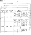
- Fig. 5 is a diagram showing an example of the movement history data 472.
- the movement history data 472 includes items of a user ID, a battery ID, a return STID, an SOC at return, a time, a moving distance, and a self-position.
- the integration processor 430 generates the movement history data 472 for each user and classifies them with a user ID.
- the movement history data 472 is an example of "position history information.”
- the items of the battery ID, the return STID, the SOC at return, and the moving distance are items based on the battery data 252, and the item of the self-position is an item based on the self-position data 372.
- the item of the time is an item based on both the battery data 252 and the self-position data 372.
- the integration processor 430 integrates the battery data 252 and the self-position data 372 by matching the time data.
- the integration processor is an example of an "integrator.”
- the integration processor 430 integrates the time data stored in the battery data 252 and the self-position data 372.
- the integration processor 430 excludes data in which the acquired date and time do not correspond to the date and time indicated in the battery data 252 from the self-position data 372 and generates the movement history data 472 of the battery 120.
- the battery data 252 stores the battery time data of "XX:00,” “XX:30,” and "XX:50.”.
- the self-position data 372 stores the terminal time data of "XX:00,” “XX:10,” and “XX:50.”
- the integration processor 430 generates the movement history data 472 for data common to the battery time of the battery data 252 and the terminal time in the self-position data 372 as shown in Fig. 5 .
- the movement history data 472 includes data of "XX:00,” “XX:30,” and “XX:50” included in both the battery time in the battery data 252 and the terminal time in the self-position data 372.
- the movement history data 472 does not include data of "XX: 10," “XX:30,” and "XX:50” which are included in the terminal time in the self-position data 372 but not included in the battery time in the battery data 252.
- the generator 440 generates a user behavior estimation model 476 for obtaining information relating to a user's behavior as a learning model.
- the generator 440 generates the user behavior estimation model 476, for example, through machine learning using each item in the movement history data 472 as input data and the user's behavior as output data.
- the user behavior estimation model 476 is an example of a "machine learning model.”
- the generator 440 generates the user behavior estimation model 476 constituted by a neural network model in which each data of the time, the self-position, the moving distance, and the SOC at return in the movement history data 472 is used as input data, and a behavioral range, a frequent use ST, and a frequent use time slot are used as output.
- the generator 440 integrates the output of the user behavior estimation model 476 when the user behavior estimation model 476 is generated.
- the generator 440 updates and generates the user behavior estimation model 476 by performing statistical processing such as regression analysis or clustering processing on the integrated value of the output of the user behavior estimation model 476.
- the generator 440 stores the generated user behavior estimation model 476 in the storage 470.
- Fig. 6 is a conceptual diagram of a process of generating the user behavior estimation model 476.
- the generator 440 generates the user behavior estimation model 476 having an input layer, a hidden layer, and an output layer. Each data of the time, the self-position, the moving distance, and the SOC at return is input to the input layer. The behavioral range, the frequent use ST, and the frequent use time slot are output from the output layer.
- the hidden layer has a multilayer neural network connecting the input layer and the output layer. The parameters of the hidden layer are optimized by performing machine learning using input to the input layer as learning data and data to be output from the output layer as training data.
- the generator 440 generates the user behavior estimation model 476 through unsupervised learning, but may generate the user behavior estimation model 476 through supervised learning.
- the estimator 450 estimates the user's behavior when a user behavior estimation timing is reached and generates user behavior data 474.
- the estimator 450 generates the user behavior data 474 on the basis of the user behavior estimation model 476 generated by the generator 440 and the movement history data 472 generated based on the battery data 252 and the self-position data 372.
- the estimator 450 estimates the user's behavior to generate the user behavior data 474 by inputting information such as time, the self-position, the moving distance, and the SOC at return included in the movement history data 472 to the user behavior estimation model 476 obtained through machine learning.
- the user behavior estimation timing may be any timing.
- the user behavior estimation timing may be set to 8 o'clock, 16 o'clock, and 0 o'clock three times a day, may be set to once a day, or the like.
- a timing at which there is a request for another device such as the charging station 200 or the portable terminal 300 to estimate the user behavior may be set as the user behavior estimation timing.
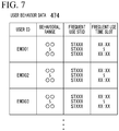
- Fig. 7 is a diagram showing an example of the user behavior data 474.
- the user behavior data 474 includes items of a user's behavioral range, a frequent use STID, and a frequent use time slot.
- the user's behavioral range is information indicating a range in which the user behaves to the electric vehicle 10.
- the user's behavioral range may be estimated in any way, for example, may be estimated as a rectangular range with the maximum value and minimum value of latitude and longitude as vertices or may be estimated as a road through which the electric vehicle 10 can pass within this range.
- the behavioral range may be estimated as a region connecting ranges of several meters in radius centered on a user's traveling region or as a region surrounded by the region.
- the frequent use STID is information indicating the STID of the charging station 200 which is frequently used by a user. Only one frequent use STID may be set or a plurality of frequent use STIDs may be estimated.
- the frequent use time slot is information indicating a main time slot in which a user uses the electric vehicle 10 having the battery unit 100 mounted therein. In the embodiment, although the items of the behavioral range, the frequent use STID, and the frequent use time slot are estimated for each user, the behavioral ranges of a plurality of user, particularly, all users, the frequent use STID, and the frequent use time slot may be estimated collectively.
- the reserver 460 In a case where desired reservation information transmitted by the portable terminal 300 is stored in the storage 470, the reserver 460 generates reservation information on the basis of the desired reservation information.
- the reservation information includes, for example, information such as the user ID of a user who has reserved the battery unit 100, the STID of the reserved charging station 200, and the reservation time.
- the reserver 460 generates the user ID included in the desired reservation information as the user ID of the reservation information.
- the reserver 460 generates information on the STID of the charging station 200 reserved on the basis of the information of the charging station 200 at which the battery unit 100 included in the desired reservation information is desired to be rented.
- the reserver 460 generates the reservation information on the basis of information of the desired rental date included in the desired reservation information.
- the reserver 460 transmits the generated reservation information to a rental and charging station using the communicator 410.
- the information processing device 400 updates the user behavior estimation model 476 when the battery data 252 transmitted by the charging station 200 is received.
- the information processing device 400 estimates the user behavior and updates the user behavior data 474 when the user behavior estimation timing is reached. Consequently, first, processing when the information processing device 400 receives the battery data 252 transmitted by the charging station 200 will be described.
- Fig. 8 is a flow chart showing an example of a flow of processes which are executed in the information processing device 400.
- the flow shown in Fig. 8 shows a flow when the battery data 252 transmitted by the charging station 200 is received.
- the information processing device 400 determines whether the battery data 252 transmitted by the charging station 200 has been received in the communicator 410 (step S110). In a case where it is determined that the battery data 252 has not been received, the information processing device 400 repeats the process of step S110 until the battery data 252 is received.
- the acquirer 420 acquires corresponding self-position data which is the self-position data 372 including self-position information of the user ID and time (terminal time) corresponding to the user ID and time (battery time) included in the battery data 252 (step S120).
- the acquirer 420 acquires the corresponding self-position data from a plurality of self-position data 372 stored in the storage 470.
- the acquirer 420 uses the communicator 410 to request the portable terminal 300 of a user having the user ID included in the battery data 252 to transmit the self-position data 372.
- the acquirer 420 acquires the self-position data 372 transmitted by the portable terminal 300 requesting the transmission of the self-position data 372 as the corresponding self-position data.
- the integration processor 430 adds data obtained by integrating the battery data 252 and the self-position data 372 acquired by the acquirer 420 to the movement history data 472 and updates the movement history data 472 (step S130).
- the generator 440 performs machine learning using each item of the updated movement history data 472 as input data and updates the user behavior estimation model 476 (step S140).
- the generator 440 stores the updated user behavior estimation model 476 in the storage 470. In this way, the information processing device 400 ends the processing of the flow chart shown in Fig. 8 .
- Fig. 9 is a flow chart showing an example of a flow of processes which are executed in the information processing device 400.
- the flow shown in Fig. 9 shows a flow when the user behavior estimation timing is reached.
- the information processing device 400 determines whether the user behavior timing has been reached (step S210). In a case where it is determined that the user behavior estimation timing has not been reached, the information processing device 400 repeats the process of step S210 until the user behavior estimation timing is reached.
- the estimator 450 reads out the movement history data 472 and the user behavior estimation model 476 which are stored in the storage 470 (step S220). Subsequently, the estimator 450 estimates the user behavior using the read-out movement history data 472 and user behavior estimation model 476 (step S230). Subsequently, the estimator 450 updates the user behavior data 474 on the basis of the estimated user behavior (step S240), and stores the updated data in the storage 470. In this way, the information processing device 400 ends the processing of the flow chart shown in Fig. 9 .
- the information processing device 400 of the above embodiment integrates the battery data 252 and the self-position data 372 by matching the battery time of the battery data 252 with the terminal time of the self-position data 372. Therefore, even in a case where the self-position information is not included in the battery data 252, the information processing device 400 can acquire the user's self-position (the self-position of the battery unit 100) by the self-position data 372 being transmitted by the portable terminal 300. Therefore, since the information on the self-position of the battery unit 100 can be acquired without providing the battery unit 100 with an instrument that detects its self-position, it is possible to detect a user's movement history.
- the information processing device 400 generates the movement history data 472 using the user ID, the battery time, and the terminal time which are included in the battery data 252 and the self-position data 372.
- the battery data 252 is generated by the clock function of the battery unit 100. Therefore, the information processing device 400 can accurately detect a user's movement history.
- the battery time is generated on the basis of the synchronous ST time
- information of a relative time which is a count value of the cycle clock of an instrument such as the BMU may be included as information included in the battery data 252 instead of the battery time.
- information equivalent to the battery time may be generated from the synchronous ST time and the information of a relative time.
- the charging station 200 may transmit information on the synchronous ST time and the relative time to the information processing device 400, and the information processing device 400 may generate information equivalent to the battery time.
- the user behavior data 474 includes items of the behavioral range, the frequent use STID, and the frequent use time slot, but may include one or two of these items.
- the user behavior data 474 may include an item of a user's moving distance.
- the user behavior data 474 may be generated by a rule base based on each data which is input to the input layer of the user behavior estimation model 476 without using the user behavior estimation model 476.
- the battery unit 100 may be reserved or the position information is acquired using the portable terminal 300 on which the battery joint use application operates
- the battery unit 100 may be reserved or the position information may be acquired by, for example, a terminal instrument dedicated to a battery joint use service.
- the terminal instrument dedicated to a battery joint use service may be, for example, an instrument lent or transferred to a user by an operator of the battery joint use service.
- the battery unit 100 rented to a user is displayed on the authentication and display 223, but may be displayed on another display or the like.
- each housing part in the slot part 221 may be provided with a light such as a spotlight, and a user may be notified of the battery unit 100 to be rented to the user by turning on or blinking this light.
- the housing state of the battery unit 100 may be notified of by means other than a display device or the like.
- the housing state of the battery unit 100 may be notified of by a voice, or a device in which a change can be felt by touching with a hand or the like may be used.
- a combination of these means may be used to notify of the housing state of the battery unit 100 through, for example, display using a display device and voice output from a speaker.
- each of a plurality of housing parts is movable, the plurality of housing parts may be fixed.
- a turntable is used as a structure for moving the housing part, other means, for example, a slider or the like may be used.
- a movement mechanism may be, for example, a so-called puzzle-type movement structure.
Landscapes
- Engineering & Computer Science (AREA)
- Business, Economics & Management (AREA)
- Theoretical Computer Science (AREA)
- Physics & Mathematics (AREA)
- General Physics & Mathematics (AREA)
- Economics (AREA)
- Strategic Management (AREA)
- Tourism & Hospitality (AREA)
- Human Resources & Organizations (AREA)
- General Business, Economics & Management (AREA)
- Health & Medical Sciences (AREA)
- Marketing (AREA)
- General Engineering & Computer Science (AREA)
- Power Engineering (AREA)
- Primary Health Care (AREA)
- General Health & Medical Sciences (AREA)
- General Chemical & Material Sciences (AREA)
- Electrochemistry (AREA)
- Chemical Kinetics & Catalysis (AREA)
- Chemical & Material Sciences (AREA)
- Manufacturing & Machinery (AREA)
- Development Economics (AREA)
- Mechanical Engineering (AREA)
- Transportation (AREA)
- Entrepreneurship & Innovation (AREA)
- Operations Research (AREA)
- Quality & Reliability (AREA)
- Public Health (AREA)
- Water Supply & Treatment (AREA)
- Management, Administration, Business Operations System, And Electronic Commerce (AREA)
- Charge And Discharge Circuits For Batteries Or The Like (AREA)
- Electric Propulsion And Braking For Vehicles (AREA)
- Time Recorders, Dirve Recorders, Access Control (AREA)
Abstract
Description
- The present invention relates to an information processing device, an information processing method, a service system, a program, and a storage medium.
- Priority is claimed on
Japanese Patent Application No. 2019-28040, filed February 20, 2019 - In a joint use service for renting and recharging detachable batteries, batteries are rented from charging stations set up in a plurality of locations and replaced at said charging stations when power has been consumed. In a conventional technique used for joint use battery services, there is a collection, charging, and distribution device that collects, charges, and distributes a portable electric energy storage device, for example, a detachable battery, when the portable electric energy storage device is mounted in an electric scooter for use, and electric power is consumed (see, for example, Patent Document 1).
- In such a joint use battery service using the above collection, charging, and distribution device, the collection, charging, and distribution device is installed at, for example, a charging station, and a user removes a detachable battery that has been charged at the charging station from its housing and attaches it to an electric scooter for use. Conversely, the user detaches a detachable battery that needs to be charged due to consumption of electric power from the electric scooter, houses it in the housing of the collection, charging, and distribution device, and replaces it with a charged detachable battery. Further, there is an information processing device in which a mobile battery is provided with a memory and a movement history of the mobile battery or information indicating the movement history is stored in this memory (see, for example, Patent Document 2).
-
- [Patent Document 1]
PCT Japanese Translation Patent Publication No. 2014-527689 - [Patent Document 2]
Japanese Patent No. 6360935 - In a joint use battery service using the above-described technique disclosed in
Patent Document 1, achieving the development of various services by detecting a user's movement history can be considered. Since the detachable battery is provided with, for example, a storage device for storing the SOC or the like of the battery, providing the battery or an electric vehicle with, for example, a position detection device and storing a position detected by the position detection device as the position of the battery in the storage device can be considered. However, since the amount of information collected by the position detection device is often large, there is a problem in that the capacity of the storage device provided for battery has to be increased. - The present invention was achieved in view of such circumstances, and one object thereof is to provide an information processing device, an information processing method, a service system, a program, and a storage medium that make it possible to detect a user's movement history.
- The following configurations are adopted in an information processing device, an information processing method, a service system, a program, and a storage medium according to this invention.
- (1) An information processing device is provided including: an acquirer configured to acquire first date and time information including information relating to a date and time at which a battery detachably installed in a moving body capable of moving by use of electric power is used and second date and time information including position information of a user's portable terminal and information relating to a date and time at which the position information is acquired; and an integrator configured to generate position history information of the battery on the basis of the first date and time information and the second date and time information acquired by the acquirer.
- (2) In (1), the integrator generates the position history information of the battery by excluding information whose acquired date and time do not correspond to the date and time indicated in the first date and time information from the second date and time information of the portable terminal.
- (3) In (1) or (2), the first date and time information is stored in a storage of the battery, and the acquirer acquires the first date and time information when the battery is kept in a keeping device for keeping the battery.
- (4) In any of (1) to (3), the first date and time information includes information clocked by a clock function of the moving body.
- (5) In any of (1) to (4), a communicator configured to communicate with the portable terminal is further included, and the acquirer acquires the position information and the second date and time information through the communicator.
- (6) In any of (1) to (5), an estimator configured to estimate the user's behavior on the basis of the position history information of the battery is further included.
- (7) In (6), the estimator estimates the user's behavior using a machine learning model that uses the position history information as input data.
- (8) In (7), the position history information of the battery includes data of at least any one of the date and time based on the first date and time information and the second date and time information, a position of the battery, or a moving distance of the moving body having the battery installed therein.
- (9) In (7) or (8), a generator configured to generate the machine learning model is further included.
- (10) In any of (6) to (9), the user's behavior includes at least any one of a time slot in which the user frequently uses the battery, the user's behavioral range, or a keeping device that keeps the battery which is frequently used by the user.
- (11) In any of (1) to (10), the acquirer further acquires information on a moving distance of the moving body having the battery installed therein.
- (12) In (1) to (11), the battery is a battery which is shared by a plurality of users.
- (13) In any of (1) to (12), the battery is provided in the moving body by means of a keeping device that keeps the battery.
- (14) In (13), the battery is able to be kept by a plurality of the keeping devices.
- (15) In (13) or (14), the keeping device acquires identification information of a user of the moving body in which the battery is provided, and the identification information of the user is stored in a storage of the battery provided in the moving body.
- (16) In any of (1) to (15), the keeping device includes the charging device that charges the battery being kept.
- (17) According to an aspect of this invention, a service system is provided including: the information processing device according to any one of
claims 1 to 16; and a keeping device in which a battery is provided in the moving body, wherein the first date and time information is information obtained by counting a cycle clock in the battery, and the keeping device synchronizes a time ascertained by the information processing device with a time stored in the battery when the battery is provided in the moving body. - (18) According to an aspect of this invention, an information processing method is provided including causing a computer of an information processing device to: acquire first date and time information including information relating to a date and time at which a battery detachably installed in a moving body capable of moving by use of electric power is used and second date and time information including position information of a user's portable terminal and information relating to a date and time at which the position information is acquired; and generate position history information of the battery on the basis of the first date and time information and the second date and time information which are acquired.
- (19) According to an aspect of this invention, a program is provided causing a computer of an information processing device to: acquire first date and time information including information relating to a date and time at which a battery detachably installed in a moving body capable of moving by use of electric power is used and second date and time information including position information of a user's portable terminal and information relating to a date and time at which the position information is acquired; and generate position history information of the battery on the basis of the first date and time information and the second date and time information which are acquired.
- (20) According to an aspect of this invention, a storage medium is provided having the program stored therein.
- According to (1) to (20), it is possible to detect a user's movement history.
-
-
Fig. 1 is an overall configuration diagram of aservice system 1 using aninformation processing device 400 of an embodiment. -
Fig. 2 is a block diagram of theservice system 1 using theinformation processing device 400 of the embodiment. -
Fig. 3 is a diagram showing an example ofbattery data 252. -
Fig. 4 is a diagram showing an example of self-position data 372. -
Fig. 5 is a diagram showing an example ofmovement history data 472. -
Fig. 6 is a diagram showing an example of a process of generating a userbehavior estimation model 476. -
Fig. 7 is a diagram showing an example ofuser behavior data 474. -
Fig. 8 is a flow chart showing an example of a flow of processes which are executed in theinformation processing device 400. -
Fig. 9 is a flow chart showing an example of a flow of processes which are executed in theinformation processing device 400. - Hereinafter, an embodiment of an information processing device, an information processing method, a service system, a program, and a storage medium of the present invention will be described with reference to the accompanying drawings. Every
battery unit 100 includes a detachable battery (hereinafter referred to as a "battery") 120 that can be attached to and detached from anelectric vehicle 10. The battery unit 100 (the battery 120) is rented to a user at acharging station 200. Thecharging station 200 charges thebattery 120 included in thebattery unit 100 before thebattery unit 100 is rented to a user. - The
charging station 200 rents and provides thebattery unit 100 to a user, and the user mounts thebattery unit 100 in theelectric vehicle 10. When renting the battery, thecharging station 200 synchronizes an ST time to be described later which is ascertained by thecharging station 200 with a battery time to be described later which is stored in the battery. The user returns thebattery unit 100 at any of a plurality ofcharging stations 200 after the amount of charging of thebattery 120 of the rentedbattery unit 100 is reduced. Thecharging station 200 rents abattery unit 100 including another chargedbattery 120 to the user who has returned thebattery unit 100. In this way, the user replaces the battery unit 100 (the battery 120) at thecharging station 200. -
Fig. 1 is an overall configuration diagram of aservice system 1 using aninformation processing device 400 of an embodiment, andFig. 2 is a block diagram of theservice system 1 using theinformation processing device 400 of the embodiment. As shown inFigs. 1 and2 , theservice system 1 includes a plurality ofbattery units 100, a plurality ofcharging stations 200, a plurality ofportable terminals 300, and theinformation processing device 400. Theinformation processing device 400 is communicably connected to the plurality ofcharging stations 200 and the plurality ofportable terminals 300 through a network NW The network NW includes, for example, the Internet, a wide area network (WAN), a local area network (LAN), a provider device, a wireless base station, and the like. - The charging
station 200 and theportable terminal 300 can transmit and receive communication data to and from theinformation processing device 400 through the network NW Theservice system 1 is a system capable of providing a share service in which thebattery 120 in thebattery unit 100 which is a driving source of theelectric vehicle 10 is shared by a plurality of users. Theinformation processing device 400 manages the plurality ofbattery units 100, the plurality of chargingstations 200, and the plurality ofportable terminals 300 in theservice system 1. The chargingstation 200 rents some of the plurality ofbattery units 100 which are being kept to a user, and accepts the return of thebattery unit 100 rented to the user. Thebattery 120 can be kept by the chargingstation 200. Theelectric vehicle 10 is an example of an "electric power device," and the chargingstation 200 is an example of a "keeping device." - The "electric power device" is not limited to an electric two-wheeled vehicle, and may be, for example, a vehicle that can travel using electric power and in which the
battery 120 can be detachably installed (such as a single-wheeled, three-wheeled, or four-wheeled vehicle), an assist-type bicycle, or the like. Instead of these vehicle-type moving bodies, the "electric power device" may be a portable charging and power feeding device carried by a person or a vehicle which is disclosed inJapanese Unexamined Patent Application, First Publication No. 2019-068552 - The
electric vehicle 10 is a vehicle in which thebattery unit 100 is detachably mounted. Theelectric vehicle 10 is a saddle-type vehicle ("electric two-wheeled vehicle") that travels using an electric motor driven by electric power supplied by thebattery 120 in thebattery unit 100. Thebattery unit 100 is mounted in theelectric vehicle 10. In the embodiment, twobattery units 100 can be mounted in theelectric vehicle 10. The number ofbattery units 100 that can be mounted in theelectric vehicle 10 may be one or may be three or more. Thebattery 120 of thebattery unit 100 supplies electric power for movement to theelectric vehicle 10. - The
electric vehicle 10 may be a hybrid electric vehicle or a fuel cell vehicle that travels by driving using a combination of thebattery unit 100 and an internal-combustion engine such as a diesel engine or a gasoline engine. Theelectric vehicle 10 that can be applied to theservice system 1 may be a vehicle such as an electric bicycle, an electric three-wheeled vehicle, an electric four-wheeled vehicle, or a hybrid vehicle, an electric kick skater, a robot, or the like in addition to an electric two-wheeled vehicle. In the embodiment, theelectric vehicle 10 is assumed to be an electric two-wheeled vehicle. - As shown in
Fig. 2 , theelectric vehicle 10 includes abattery sensor 12 and awheel speed sensor 14. Theelectric vehicle 10 can transmit and receive information to and from the installedbattery unit 100 through a communication line or the like which is not shown. Thebattery sensor 12 includes, for example, various types of sensors such as a current sensor, a voltage sensor, and a temperature sensor that detect the current value, voltage value, temperature, and the like of thebattery 120 in the installedbattery unit 100. Thebattery sensor 12 transmits the detection results of various types of sensors to thebattery unit 100 using a communication device which is not shown. - The
wheel speed sensor 14 is provided on, for example, the wheel of theelectric vehicle 10 to detect the rotational speed of the wheel. Thewheel speed sensor 14 outputs the detected rotational speed of the wheel to an arithmetic operation device which is not shown, and the arithmetic operation device calculates the vehicle speed of theelectric vehicle 10 from the output rotational speed of the wheel. The arithmetic operation device transmits information on the calculated vehicle speed to thebattery unit 100 using a communication device which is not shown. - As shown in
Fig. 1 , thebattery unit 100 is mounted in theelectric vehicle 10 and is kept in acharging device 220 at the chargingstation 200. Thebattery unit 100 is a cassette which is detachably installed in theelectric vehicle 10. As shown inFig. 2 , thebattery unit 100 includes thebattery 120, abattery communicator 140, and abattery control device 180. - The
battery 120 is a power storage device (secondary battery) such as, for example, a lithium-ion battery. Thebattery 120 is installed in theelectric vehicle 10 to supply electric power for traveling to theelectric vehicle 10. The electric power supplied by thebattery 120 may be used as electric power other than for traveling. - The
battery communicator 140 is an instrument for communicating with theelectric vehicle 10 and the chargingstation 200. By thebattery unit 100 being installed in theelectric vehicle 10, thebattery communicator 140 can transmit and receive information to and from theelectric vehicle 10 through a communication line. By thebattery 120 of thebattery unit 100 being connected to acharger 227 to be described later, thebattery communicator 140 can transmit and receive information to and from the chargingstation 200 through a communication line. - The
battery control device 180 includes, for example, abattery controller 182, abattery clocker 184, and abattery storage 186. Thebattery controller 182 includes, for example, a battery management unit (BMU; controller). The BMU controls charging or discharging of thebattery 120. For example, the BMU controls charging of thebattery 120 when thebattery unit 100 is kept in the chargingstation 200, and controls charging or discharging of thebattery 120 when thebattery unit 100 is installed in theelectric vehicle 10. Thebattery storage 186 stores a battery ID. Thebattery storage 186 is an example of a "storage." The battery ID is, for example, identification information of the battery unit 100 (or the battery 120) consisting of different numbers assigned to each battery unit 100 (or battery 120) in order to individually identify the plurality of battery units 100 (or batteries 120). - The
battery controller 182 acquires the detection result transmitted by thebattery sensor 12 of theelectric vehicle 10 using thebattery communicator 140. Thebattery controller 182 calculates the state of charge (SOC) of thebattery 120 on the basis of the acquired detection result. Thebattery controller 182 stores the calculated SOC of thebattery 120 in thebattery storage 186. Thebattery controller 182 acquires information on the vehicle speed of theelectric vehicle 10 transmitted by theelectric vehicle 10 using thebattery communicator 140. Thebattery controller 182 calculates the moving distance of theelectric vehicle 10 by integrating the acquired information on the vehicle speed of theelectric vehicle 10. Thebattery controller 182 stores the calculated moving distance of theelectric vehicle 10 in thebattery storage 186. The moving distance of theelectric vehicle 10 may be calculated by theelectric vehicle 10 and transmitted to thebattery unit 100. - The
battery controller 182 uses thebattery communicator 140 to acquire information on the user ID of a user who possesses theelectric vehicle 10 which is transmitted by the chargingstation 200 that rents thebattery unit 100. The user ID is, for example, identification information of a user consisting of different numbers assigned to each user in order to individually identify a plurality of users. Thebattery controller 182 stores the acquired information on the user ID in thebattery storage 186. - The
battery controller 182 acquires a time provided by the charging station 200 (hereinafter referred to as an "ST time") as a synchronous ST time when thebattery 120 is connected to thecharger 227. The ST time is a time measured by anST clocker 248 to be described later at the chargingstation 200. Thebattery controller 182 stores information on the acquired synchronous ST time in thebattery storage 186. - The
battery clocker 184 counts, for example, the cycle clock of the BMU and detects a relative time in thebattery unit 100. Thebattery clocker 184 calculates a virtual time in the battery unit 100 (hereinafter referred to as a "battery time") on the basis of the detected relative time and the synchronous ST time provided by the chargingstation 200. Thebattery clocker 184 outputs information on the calculated battery time to thebattery controller 182. - The
battery controller 182 calculates the moving distance of theelectric vehicle 10 at each predetermined battery time acquisition timing, and stores the calculated moving distance in thebattery storage 186 in association with the battery time. The battery time acquisition timing may be set in any way. For example, the battery time acquisition timing may be every minute, every ten minutes, or every hour. The battery time acquisition timing may be set at regular intervals of time, or the intervals of time may be changed in accordance with a time slot. For example, the battery time acquisition timing may be every ten minutes in the daytime, but every hour in the nighttime. - The
battery clocker 184 may count the cycle clock of an electronic instrument other than the BMU. Thebattery clocker 184 may count, for example, the cycle clock of another electronic instrument in thebattery unit 100 or an electronic instrument provided in theelectric vehicle 10. Thebattery clocker 184 may acquire the battery time through means other than counting the cycle clock of the electronic instrument. - The charging
station 200 is a facility for keeping and charging thebattery unit 100, and is installed at a plurality of places. As shown inFigs. 1 and2 , the chargingstation 200 includes thecharging device 220 and a charging station control device (hereinafter referred to as an "ST control device") 240. The chargingdevice 220 includes aslot part 221 and an authentication and display 223 shown inFig. 1 and thecharger 227 shown inFig. 2 . - The
slot part 221 includes anupper slot part 221U and a lower slot part 221L. Since theupper slot part 221U and the lower slot part 221L have a configuration common to each other, the configuration of theupper slot part 221U will be described as a representative. Theupper slot part 221U includes, for example, a turntable that rotates around a vertical axis. Battery housing parts (hereinafter referred to as "housing parts") are provided on the turntable. The housing parts are provided in regions partitioned into four equal parts in a plan view of the turntable. - A takeout port is provided on the surface of the
charging device 220. A user can put thebattery unit 100 in and take it out of a housing part located at the takeout port from the outside. The housing part located at the takeout port can be replaced by rotating the turntable. The four housing parts are partitioned by a partition plate. The partition plate is formed of, for example, a transparent material. - The authentication and
display 223 is an instrument having at least an authentication function and a display function. The authentication and display 223 can read recording information of an NFC card (not shown) carried by a user using, for example, near field communication (NFC). Thereby, the chargingstation 200 authenticates a user who has a right to use a share service using the user ID included in this recording information. The authentication and display 223 can detect radio waves which are transmitted by a radio wave transmitter possessed by a user. The authentication anddisplay 223 detects a user who has reserved use of thebattery unit 100 approaching the chargingstation 200 on the basis of the detection result of the radio waves transmitted by the radio wave transmitter operated by the user. - The authentication and
display 223 includes, for example, a touch panel (a display panel with a touch sensor). Thereby, it is possible to input necessary information in accordance with a user's operation, and to provide various types of visual information to the user. The authentication anddisplay 223 is disposed at the upper left part of thecharging device 220. The authentication anddisplay 223 displays various types of information. For example, the authentication anddisplay 223 displays information for notifying of a housing part in which a battery unit to be rented to a user is housed. - The
charger 227 shown inFig. 2 is provided on the inner side of each housing part at theslot part 221 shown inFig. 1 . Thecharger 227 can be connected to and charged from thebattery 120 of thebattery unit 100. A power supply for supplying electric power to thebattery 120 is connected to thecharger 227. - As shown in
Fig. 2 , theST control device 240 includes anST communicator 242, anST controller 244, a chargingcontroller 246, theST clocker 248, and anST storage 250. TheST controller 244 and the chargingcontroller 246 are realized by a processor such as, for example, a central processing unit (CPU) executing a program (software) stored in theST storage 250. Some or all of these functional units may be realized by hardware (a circuit unit; including circuitry) such as a large scale integration (LSI), an application specific integrated circuit (ASIC), a field-programmable gate array (FPGA), or a graphics processing unit (GPU), or may be realized by software and hardware in cooperation. The program may be stored in a storage device such as a hard disk drive (HDD) or a flash memory (non-transitory storage medium) in advance, may be stored in a detachable storage medium such as a DVD or a CD-ROM (non-transitory storage medium), or may be installed by the storage medium being mounted in a drive device. TheST storage 250 is realized by the above-described storage device. TheST storage 250 stores an STID of the chargingstation 200 provided with theST control device 240. The STID is, for example, identification information of the chargingstation 200 consisting of different numbers assigned to each chargingstation 200 in order to individually identify the plurality of chargingstations 200. - The
ST communicator 242 is an instrument for communicating with theelectric vehicle 10 and theinformation processing device 400. By thebattery 120 of thebattery unit 100 being connected to thecharger 227, theST communicator 242 can transmit and receive information to and from thebattery unit 100 through a communication line. - The
ST communicator 242 transmits and receives information to and from theinformation processing device 400 through the network NW TheST communicator 242 includes, for example, a communication interface such as a wireless module for connecting a cellular network or a Wi-Fi network, or a network card for connection to the network NW - When the
battery 120 of thebattery unit 100 is connected to thecharger 227, theST controller 244 reads out information stored in thebattery storage 186 of thebattery unit 100 through theST communicator 242 and thebattery communicator 140. The information which is read out by theST controller 244 is, for example, information on the battery ID, the user ID, the current SOC (at return) (hereinafter referred to as the "SOC at return"), the synchronous ST time, the battery time, and the moving distance of theelectric vehicle 10 for each battery time. The chargingstation 200 has theST controller 244. - The
ST controller 244 calculates the amount of charging of thebattery 120 on the basis of the information or the like of the SOC read out from thebattery unit 100 and outputs information on the calculated amount of charging to the chargingcontroller 246. TheST controller 244 generates and acquiresbattery data 252 on the basis of various types of information read out from thebattery storage 186 of thebattery unit 100 and the STID stored in theST storage 250. Thebattery data 252 is history information of the battery time which is read out from thebattery storage 186. Thebattery data 252 is information including the date and time when thebattery 120 has been used. Thebattery data 252 is an example of "first date and time information." -
Fig. 3 is a diagram showing an example of thebattery data 252. As shown inFig. 3 , thebattery data 252 includes items of a battery ID, a user ID, a return STID, an SOC at return, a synchronous ST time, a battery time, and a moving distance for each battery time. Among these items, data of items of the battery ID, the user ID, the SOC at return, the synchronous ST time, the battery time, and the moving distance for each battery time is data which is read out from thebattery unit 100. The return STID is an STID stored in theST storage 250. TheST controller 244 stores the generatedbattery data 252 in theST storage 250. TheST storage 250 stores thebattery data 252 for all thebattery units 100 kept in theslot part 221. - The
ST controller 244 acquires reservation information transmitted by theinformation processing device 400 using theST communicator 242. In a case where the reservation information is output by theinformation processing device 400, theST controller 244 prepares for a user who rents thebattery unit 100 to perform authentication. For example, in a case where a user corresponding to the reservation information which is output by theST communicator 242 visits the office, theST controller 244 performs display control and authentication control of the authentication anddisplay 223. After a reservation user arrives at the chargingstation 200 and performs authentication through the authentication anddisplay 223, theST controller 244 causes the authentication anddisplay 223 to display information relating to thebattery unit 100 to be rented to the user. - The charging
controller 246 charges thebattery 120 of thebattery unit 100 housed in the housing part of theslot part 221 on the basis of information or the like of the amount of charging which is output by theST controller 244. The chargingcontroller 246 charges thebattery 120 with electric power until thebattery 120 is fully charged. - The
ST clocker 248 is constituted by, for example, a radio clock, and clocks an absolute time. The time clocked by theST clocker 248 is set to an ST time. The ST time is generated by the clock function of the battery unit 100 (the battery 120). The ST time may be generated by the clock function of theelectric vehicle 10. TheST clocker 248 is only required to be a timepiece or the like that clocks an absolute time, and may be, for example, a timepiece or the like other than a radio clock. When thebattery unit 100 is rented to a user, the chargingstation 200 uses theST communicator 242 to transmit the ST time to thebattery unit 100 as the synchronous ST time and synchronize the synchronous ST time with the battery time. - <
Portable terminal 300> - The
portable terminal 300 is, for example, a terminal device such as a smartphone, a tablet terminal, or a notebook personal computer possessed by a user who is provided with a battery, for example, rents the battery. In theportable terminal 300, a user agent (UA) such as an application program or a browser operates to support a share service of thebattery 120. Theportable terminal 300 can refer to a station map showing the location of the chargingstation 200. The station map may be held by theinformation processing device 400, or may be downloaded to theportable terminal 300. Theportable terminal 300 can acquire peripheral station information relating to the chargingstations 200 around a user by searching the station map using the current position of the user. In the embodiment, it is assumed that theportable terminal 300 is a smartphone and the application program (battery joint use application) is being started up. Theportable terminal 300 accepts a user's reservation of thebattery unit 100. When the user reserves the rental of thebattery unit 100, the rental of the reservedbattery unit 100 to non-reservation users other than the reservation user is disabled. - For example, the user can search for a
nearby charging station 200 using theportable terminal 300, and in a case where the searched chargingstation 200 has a rentable thebattery unit 100, the user can reserve thebattery unit 100. When a plurality of chargingstations 200 are searched for, the user can select a chargingstation 200 to be used. - As shown in
Fig. 2 , theportable terminal 300 includes aterminal communicator 310, aterminal clocker 320, a self-position detector 330, atouch panel 340, aterminal controller 350, and aterminal storage 370. Theterminal communicator 310 transmits and receives information to and from theinformation processing device 400 through the network NW Theterminal communicator 310 includes, for example, a communication interface such as a wireless module for connecting a cellular network or a Wi-Fi network, or a network card for connection to the network NW - The
terminal clocker 320 is constituted by, for example, a radio clock, and clocks an absolute time. Theterminal clocker 320 is only required to be a timepiece or the like that clocks an absolute time, and may be, for example, a timepiece or the like other than a radio clock. Theterminal clocker 320 outputs the clocked absolute time (hereinafter referred to as the "terminal time") to theterminal controller 350. - The self-
position detector 330 includes, for example, a global navigation satellite system (GNSS) receiver and a self-position detection controller. The GNSS receiver measures its position (the self-position of the battery unit 100) on the basis of radio waves arriving from a GNSS satellite (for example, a GPS satellite). The self-position detection controller includes, for example, a CPU and various types of storage devices, and detects the self-position of theportable terminal 300. The self-position detector 330 generates information of the self-position on the basis of the detected self-position of theportable terminal 300 and outputs the generated information of the self-position as a user's position information to theterminal controller 350 using the receiver. For example, in a case where the user is an occupant (user) who boards theelectric vehicle 10, theportable terminal 300 becomes a portable terminal of the occupant of theelectric vehicle 10. In this case, the position information of the self-position which is transmitted by the portable terminal becomes position information of the occupant who boards theelectric vehicle 10. - The
touch panel 340 is a display panel with a touch sensor serving both as a display device that displays various types of information or images and an input device that accepts a user's operation. Thetouch panel 340 displays, for example, a graphical user interface (GUI) switch, and outputs information according to the operation of the GUI switch to theterminal controller 350. A user can reserve the rental of thebattery unit 100 by operating thetouch panel 340 of theportable terminal 300. - The
terminal controller 350 acquires the self-position of theportable terminal 300 at each predetermined terminal time acquisition timing and stores the acquired self-position in thebattery storage 186 in association with the terminal time. The terminal time acquisition timing may be set in any way. For example, the terminal time acquisition timing may be every minute, every ten minutes, or every hour. The terminal time acquisition timing may be set at regular intervals of time, or the intervals of time may be changed in accordance with a time slot. For example, the terminal time acquisition timing is every ten minutes in the daytime, but may be every hour in the nighttime. - The
terminal controller 350 generates self-position data 372 on the basis of the acquired terminal time and information of the self-position.Fig. 4 is a diagram showing an example of the self-position data 372. As shown inFig. 4 , the self-position data 372 includes items of a user ID, a terminal time, and a self-position for each terminal time. The self-position data 372 is data in which self-position and a measurement time are associated with each other. The self-position data 372 is information including the date and time when information of a user's self-position is acquired. The self-position data 372 is an example of "second date and time information." Theterminal controller 350 transmits the generated self-position data 372 to theinformation processing device 400 using theterminal communicator 310 when the self-position data 372 is generated or in response to a request from theinformation processing device 400. - In a case where a user performs a reservation operation of the
touch panel 340 for thebattery unit 100 when the battery joint use application is being started up, theterminal controller 350 generates desired reservation information according to the user's reservation operation. Theterminal controller 350 transmits the generated desired reservation information to theinformation processing device 400 using theterminal communicator 310. The desired reservation information includes, for example, information on the user ID, the chargingstation 200 at which thebattery unit 100 is desired to be rented, and a desired rental date. - The
information processing device 400 functions as a web server or an application server, and acquires information uploaded by theportable terminal 300 while various types of information are provided for theportable terminal 300. Theinformation processing device 400 communicates with the chargingstation 200 to thereby transmit information indicating that thebattery unit 100 has been reserved by a user to the chargingstation 200 and designate thebattery unit 100 to be rented to the user. - The
information processing device 400 includes, for example, acommunicator 410, anacquirer 420, anintegration processor 430, agenerator 440, anestimator 450, areserver 460, and astorage 470. Theacquirer 420, theintegration processor 430, thegenerator 440, theestimator 450, and thereserver 460 are realized by a hardware processor such as, for example, a CPU executing a program (software). Some or all of these components may be realized by hardware such as an LSI, an ASIC, an FPGA, or a GPU, or may be realized by software and hardware in cooperation. The program may be stored in a storage device such as an HDD or a flash memory (non-transitory storage medium) in advance, may be stored in a detachable storage medium such as a DVD or a CD-ROM (non-transitory storage medium) or may be installed by the storage medium being installed in a drive device. Thestorage 470 is realized by the above-described storage device. - The
storage 470 stores information such as battery IDs for the plurality ofbatteries 120 used in theservice system 1, and STIDs and locations of the plurality of chargingstations 200, and the like. In a case where thebattery 120 and the chargingstation 200 are newly added to theservice system 1, thestorage 470 additionally stores the battery ID, STID, and the like thereof. - The
communicator 410 transmits and receives information to and from the chargingstation 200, theportable terminal 300, and the like through the network NW Thecommunicator 410 includes, for example, a communication interface such as a wireless module for connecting a cellular network or a Wi-Fi network, or a network card for connection to the network NW Thecommunicator 410 receives various types of information transmitted by the chargingstation 200, theportable terminal 300, and the like. - The
acquirer 420 acquires various types of information using thecommunicator 410. For example, theacquirer 420 acquires thebattery data 252 transmitted by the chargingstation 200 and the self-position data 372 transmitted by theportable terminal 300. Theacquirer 420 stores the acquiredbattery data 252 and self-position data 372 in thestorage 470. - The
integration processor 430 integrates thebattery data 252 and the self-position data 372 which are stored in thestorage 470 to generatemovement history data 472 and stores the generated data in thestorage 470.Fig. 5 is a diagram showing an example of themovement history data 472. As shown inFig. 5 , themovement history data 472 includes items of a user ID, a battery ID, a return STID, an SOC at return, a time, a moving distance, and a self-position. Theintegration processor 430 generates themovement history data 472 for each user and classifies them with a user ID. Themovement history data 472 is an example of "position history information." - The items of the battery ID, the return STID, the SOC at return, and the moving distance are items based on the
battery data 252, and the item of the self-position is an item based on the self-position data 372. The item of the time is an item based on both thebattery data 252 and the self-position data 372. Theintegration processor 430 integrates thebattery data 252 and the self-position data 372 by matching the time data. The integration processor is an example of an "integrator." - The
integration processor 430 integrates the time data stored in thebattery data 252 and the self-position data 372. Theintegration processor 430 excludes data in which the acquired date and time do not correspond to the date and time indicated in thebattery data 252 from the self-position data 372 and generates themovement history data 472 of thebattery 120. For example, as shown inFig. 3 , thebattery data 252 stores the battery time data of "XX:00," "XX:30," and "XX:50.". On the other hand, as shown inFig. 4 , the self-position data 372 stores the terminal time data of "XX:00," "XX:10," and "XX:50." Theintegration processor 430 generates themovement history data 472 for data common to the battery time of thebattery data 252 and the terminal time in the self-position data 372 as shown inFig. 5 . For example, themovement history data 472 includes data of "XX:00," "XX:30," and "XX:50" included in both the battery time in thebattery data 252 and the terminal time in the self-position data 372. On the other hand, themovement history data 472 does not include data of "XX: 10," "XX:30," and "XX:50" which are included in the terminal time in the self-position data 372 but not included in the battery time in thebattery data 252. - The
generator 440 generates a userbehavior estimation model 476 for obtaining information relating to a user's behavior as a learning model. Thegenerator 440 generates the userbehavior estimation model 476, for example, through machine learning using each item in themovement history data 472 as input data and the user's behavior as output data. The userbehavior estimation model 476 is an example of a "machine learning model." - For example, as shown in
Fig. 7 , thegenerator 440 generates the userbehavior estimation model 476 constituted by a neural network model in which each data of the time, the self-position, the moving distance, and the SOC at return in themovement history data 472 is used as input data, and a behavioral range, a frequent use ST, and a frequent use time slot are used as output. - The
generator 440 integrates the output of the userbehavior estimation model 476 when the userbehavior estimation model 476 is generated. Thegenerator 440 updates and generates the userbehavior estimation model 476 by performing statistical processing such as regression analysis or clustering processing on the integrated value of the output of the userbehavior estimation model 476. Thegenerator 440 stores the generated userbehavior estimation model 476 in thestorage 470. -
Fig. 6 is a conceptual diagram of a process of generating the userbehavior estimation model 476. As shown inFig. 6 , thegenerator 440 generates the userbehavior estimation model 476 having an input layer, a hidden layer, and an output layer. Each data of the time, the self-position, the moving distance, and the SOC at return is input to the input layer. The behavioral range, the frequent use ST, and the frequent use time slot are output from the output layer. The hidden layer has a multilayer neural network connecting the input layer and the output layer. The parameters of the hidden layer are optimized by performing machine learning using input to the input layer as learning data and data to be output from the output layer as training data. Thegenerator 440 generates the userbehavior estimation model 476 through unsupervised learning, but may generate the userbehavior estimation model 476 through supervised learning. - The
estimator 450 estimates the user's behavior when a user behavior estimation timing is reached and generatesuser behavior data 474. Theestimator 450 generates theuser behavior data 474 on the basis of the userbehavior estimation model 476 generated by thegenerator 440 and themovement history data 472 generated based on thebattery data 252 and the self-position data 372. For example, theestimator 450 estimates the user's behavior to generate theuser behavior data 474 by inputting information such as time, the self-position, the moving distance, and the SOC at return included in themovement history data 472 to the userbehavior estimation model 476 obtained through machine learning. - The user behavior estimation timing may be any timing. For example, the user behavior estimation timing may be set to 8 o'clock, 16 o'clock, and 0 o'clock three times a day, may be set to once a day, or the like. Alternatively, a timing at which there is a request for another device such as the charging
station 200 or theportable terminal 300 to estimate the user behavior may be set as the user behavior estimation timing. -
Fig. 7 is a diagram showing an example of theuser behavior data 474. As shown inFig. 7 , theuser behavior data 474 includes items of a user's behavioral range, a frequent use STID, and a frequent use time slot. The user's behavioral range is information indicating a range in which the user behaves to theelectric vehicle 10. The user's behavioral range may be estimated in any way, for example, may be estimated as a rectangular range with the maximum value and minimum value of latitude and longitude as vertices or may be estimated as a road through which theelectric vehicle 10 can pass within this range. Alternatively, the behavioral range may be estimated as a region connecting ranges of several meters in radius centered on a user's traveling region or as a region surrounded by the region. - The frequent use STID is information indicating the STID of the charging
station 200 which is frequently used by a user. Only one frequent use STID may be set or a plurality of frequent use STIDs may be estimated. The frequent use time slot is information indicating a main time slot in which a user uses theelectric vehicle 10 having thebattery unit 100 mounted therein. In the embodiment, although the items of the behavioral range, the frequent use STID, and the frequent use time slot are estimated for each user, the behavioral ranges of a plurality of user, particularly, all users, the frequent use STID, and the frequent use time slot may be estimated collectively. - In a case where desired reservation information transmitted by the
portable terminal 300 is stored in thestorage 470, thereserver 460 generates reservation information on the basis of the desired reservation information. The reservation information includes, for example, information such as the user ID of a user who has reserved thebattery unit 100, the STID of the reserved chargingstation 200, and the reservation time. - The
reserver 460 generates the user ID included in the desired reservation information as the user ID of the reservation information. Thereserver 460 generates information on the STID of the chargingstation 200 reserved on the basis of the information of the chargingstation 200 at which thebattery unit 100 included in the desired reservation information is desired to be rented. Thereserver 460 generates the reservation information on the basis of information of the desired rental date included in the desired reservation information. Thereserver 460 transmits the generated reservation information to a rental and charging station using thecommunicator 410. - Next, an example of processing in the
information processing device 400 will be described. Theinformation processing device 400 updates the userbehavior estimation model 476 when thebattery data 252 transmitted by the chargingstation 200 is received. Theinformation processing device 400 estimates the user behavior and updates theuser behavior data 474 when the user behavior estimation timing is reached. Consequently, first, processing when theinformation processing device 400 receives thebattery data 252 transmitted by the chargingstation 200 will be described. -
Fig. 8 is a flow chart showing an example of a flow of processes which are executed in theinformation processing device 400. The flow shown inFig. 8 shows a flow when thebattery data 252 transmitted by the chargingstation 200 is received. Theinformation processing device 400 determines whether thebattery data 252 transmitted by the chargingstation 200 has been received in the communicator 410 (step S110). In a case where it is determined that thebattery data 252 has not been received, theinformation processing device 400 repeats the process of step S110 until thebattery data 252 is received. - When it is determined that the
battery data 252 has been received, theacquirer 420 acquires corresponding self-position data which is the self-position data 372 including self-position information of the user ID and time (terminal time) corresponding to the user ID and time (battery time) included in the battery data 252 (step S120). When the corresponding self-position data is acquired, theacquirer 420 acquires the corresponding self-position data from a plurality of self-position data 372 stored in thestorage 470. In a case where there is no corresponding self-position data in the self-position data 372 stored in thestorage 470, theacquirer 420 uses thecommunicator 410 to request theportable terminal 300 of a user having the user ID included in thebattery data 252 to transmit the self-position data 372. Theacquirer 420 acquires the self-position data 372 transmitted by theportable terminal 300 requesting the transmission of the self-position data 372 as the corresponding self-position data. - Subsequently, the
integration processor 430 adds data obtained by integrating thebattery data 252 and the self-position data 372 acquired by theacquirer 420 to themovement history data 472 and updates the movement history data 472 (step S130). Subsequently, thegenerator 440 performs machine learning using each item of the updatedmovement history data 472 as input data and updates the user behavior estimation model 476 (step S140). Thegenerator 440 stores the updated userbehavior estimation model 476 in thestorage 470. In this way, theinformation processing device 400 ends the processing of the flow chart shown inFig. 8 . - Next, processing of the
information processing device 400 when the user behavior estimation timing is reached will be described.Fig. 9 is a flow chart showing an example of a flow of processes which are executed in theinformation processing device 400. The flow shown inFig. 9 shows a flow when the user behavior estimation timing is reached. Theinformation processing device 400 determines whether the user behavior timing has been reached (step S210). In a case where it is determined that the user behavior estimation timing has not been reached, theinformation processing device 400 repeats the process of step S210 until the user behavior estimation timing is reached. - In a case where it is determined that the user behavior estimation timing has been reached, the
estimator 450 reads out themovement history data 472 and the userbehavior estimation model 476 which are stored in the storage 470 (step S220). Subsequently, theestimator 450 estimates the user behavior using the read-outmovement history data 472 and user behavior estimation model 476 (step S230). Subsequently, theestimator 450 updates theuser behavior data 474 on the basis of the estimated user behavior (step S240), and stores the updated data in thestorage 470. In this way, theinformation processing device 400 ends the processing of the flow chart shown inFig. 9 . - The
information processing device 400 of the above embodiment integrates thebattery data 252 and the self-position data 372 by matching the battery time of thebattery data 252 with the terminal time of the self-position data 372. Therefore, even in a case where the self-position information is not included in thebattery data 252, theinformation processing device 400 can acquire the user's self-position (the self-position of the battery unit 100) by the self-position data 372 being transmitted by theportable terminal 300. Therefore, since the information on the self-position of thebattery unit 100 can be acquired without providing thebattery unit 100 with an instrument that detects its self-position, it is possible to detect a user's movement history. - In the
service system 1 of the above embodiment, theinformation processing device 400 generates themovement history data 472 using the user ID, the battery time, and the terminal time which are included in thebattery data 252 and the self-position data 372. Thebattery data 252 is generated by the clock function of thebattery unit 100. Therefore, theinformation processing device 400 can accurately detect a user's movement history. - In the above-described embodiment, although the battery time is generated on the basis of the synchronous ST time, information of a relative time which is a count value of the cycle clock of an instrument such as the BMU may be included as information included in the
battery data 252 instead of the battery time. In this case, in the chargingstation 200, information equivalent to the battery time may be generated from the synchronous ST time and the information of a relative time. Alternatively, the chargingstation 200 may transmit information on the synchronous ST time and the relative time to theinformation processing device 400, and theinformation processing device 400 may generate information equivalent to the battery time. - In the above-described embodiment, the
user behavior data 474 includes items of the behavioral range, the frequent use STID, and the frequent use time slot, but may include one or two of these items. Theuser behavior data 474 may include an item of a user's moving distance. Theuser behavior data 474 may be generated by a rule base based on each data which is input to the input layer of the userbehavior estimation model 476 without using the userbehavior estimation model 476. - In the above-described embodiment, although the
battery unit 100 is reserved or the position information is acquired using theportable terminal 300 on which the battery joint use application operates, thebattery unit 100 may be reserved or the position information may be acquired by, for example, a terminal instrument dedicated to a battery joint use service. In this case, the terminal instrument dedicated to a battery joint use service may be, for example, an instrument lent or transferred to a user by an operator of the battery joint use service. - In the above-described embodiment, the
battery unit 100 rented to a user is displayed on the authentication anddisplay 223, but may be displayed on another display or the like. For example, each housing part in theslot part 221 may be provided with a light such as a spotlight, and a user may be notified of thebattery unit 100 to be rented to the user by turning on or blinking this light. - The housing state of the
battery unit 100 may be notified of by means other than a display device or the like. For example, the housing state of thebattery unit 100 may be notified of by a voice, or a device in which a change can be felt by touching with a hand or the like may be used. A combination of these means may be used to notify of the housing state of thebattery unit 100 through, for example, display using a display device and voice output from a speaker. - In the above-described embodiment, although each of a plurality of housing parts is movable, the plurality of housing parts may be fixed. Although a turntable is used as a structure for moving the housing part, other means, for example, a slider or the like may be used. In this case, a movement mechanism may be, for example, a so-called puzzle-type movement structure.
- Although modes for carrying out the present invention have been described above using the embodiments, the present invention is not limited to the embodiments and various modifications and replacements can be applied without departing from the spirit and scope of the present invention.
-
- 1
- Service system
- 10
- Electric vehicle
- 100
- Battery
- 120
- Battery
- 140
- Battery communicator
- 180
- Battery control device
- 182
- Battery controller
- 184
- Battery clocker
- 186
- Battery storage
- 200
- Charging station
- 220
- Charging device
- 240
- ST control device
- 242
- ST communicator
- 244
- ST controller
- 246
- charging controller
- 248
- ST clocker
- 250
- ST storage
- 252
- Battery data
- 300
- Portable terminal
- 310
- Terminal communicator
- 320
- Terminal clocker
- 330
- Self-position detector
- 340
- Touch panel
- 350
- Terminal controller
- 370
- Terminal storage
- 372
- Self-position data
- 400
- Information processing device
- 410
- Communicator
- 420
- Acquirer
- 430
- Integration processor
- 440
- Generator
- 450
- Estimator
- 460
- Reserver
- 470
- Storage
- 472
- Movement history data
- 474
- User behavior data
- 476
- User behavior estimation model
Claims (20)
- An information processing device comprising:an acquirer configured to acquire first date and time information including information relating to a date and time at which a battery detachably installed in a moving body capable of moving by use of electric power is used and second date and time information including position information of a user's portable terminal and information relating to a date and time at which the position information is acquired; andan integrator configured to generate position history information of the battery on the basis of the first date and time information and the second date and time information acquired by the acquirer.
- The information processing device according to claim 1, wherein the integrator generates the position history information of the battery by excluding information whose acquired date and time do not correspond to the date and time indicated in the first date and time information from the second date and time information of the portable terminal.
- The information processing device according to claim 1 or 2, wherein the first date and time information is stored in a storage of the battery, and
the acquirer acquires the first date and time information when the battery is kept in a keeping device for keep the battery. - The information processing device according to any one of claims 1 to 3,
wherein the first date and time information includes information clocked by a clock function of the moving body. - The information processing device according to any one of claims 1 to 4, further comprising a communicator configured to communicate with the portable terminal,
wherein the acquirer acquires the position information and the second date and time information through the communicator. - The information processing device according to any one of claims 1 to 5, further comprising an estimator configured to estimate the user's behavior on the basis of the position history information of the battery.
- The information processing device according to claim 6, wherein the estimator estimates the user's behavior using a machine learning model that uses the position history information of the battery as input data.
- The information processing device according to claim 7, wherein the position history information of the battery includes data of at least any one of the date and time based on the first date and time information and the second date and time information, a position of the battery, or a moving distance of the moving body having the battery installed therein.
- The information processing device according to claim 7 or 8, further comprising a generator configured to generate the machine learning model.
- The information processing device according to any one of claims 6 to 9,
wherein the user's behavior includes at least any one of a time slot in which the user frequently uses the battery, the user's behavioral range, or a keeping device that keeps the battery which is frequently used by the user. - The information processing device according to any one of claims 1 to 10,
wherein the acquirer further acquires information on a moving distance of the moving body having the battery installed therein. - The information processing device according to any one of claims 1 to 11,
wherein the battery is a battery which is shared by a plurality of users. - The information processing device according to any one of claims 1 to 12,
wherein the battery is provided in the moving body by means of a keeping device that keeps the battery. - The information processing device according to claim 13, wherein the battery is able to be kept by a plurality of the keeping devices.
- The information processing device according to claim 13 or 14, wherein the keeping device acquires identification information of a user of the moving body in which the battery is provided, and
the identification information of the user is stored in a storage of the battery provided in the moving body. - The information processing device according to any one of claims 1 to 15,
wherein the keeping device that keeps the battery includes the charging device that charges the battery being kept. - A service system comprising:the information processing device according to any one of claims 1 to 16; anda keeping device in which a battery is provided in the moving body,wherein the first date and time information is information obtained by counting a cycle clock in the battery, andthe keeping device synchronizes a time ascertained by the information processing device with a time stored in the battery when the battery is provided in the moving body.
- An information processing method comprising causing a computer of an information processing device to:acquire first date and time information including information relating to a date and time at which a battery detachably installed in a moving body capable of moving by use of electric power is used and second date and time information including position information of a user's portable terminal and information relating to a date and time at which the position information is acquired; andgenerate position history information of the battery on the basis of the first date and time information and the second date and time information which are acquired.
- A program causing a computer of an information processing device to:acquire first date and time information including information relating to a date and time at which a battery detachably installed in a moving body capable of moving by use of electric power is used and second date and time information including position information of a user's portable terminal and information relating to a date and time at which the position information is acquired; andgenerate position history information of the battery on the basis of the first date and time information and the second date and time information which are acquired.
- A storage medium having the program according to claim 19 stored therein.
Applications Claiming Priority (2)
| Application Number | Priority Date | Filing Date | Title |
|---|---|---|---|
| JP2019028040 | 2019-02-20 | ||
| PCT/JP2020/006808 WO2020171170A1 (en) | 2019-02-20 | 2020-02-20 | Information processing device, information processing method, service system, program, and storage medium |
Publications (3)
| Publication Number | Publication Date |
|---|---|
| EP3930073A1 true EP3930073A1 (en) | 2021-12-29 |
| EP3930073A4 EP3930073A4 (en) | 2022-04-13 |
| EP3930073B1 EP3930073B1 (en) | 2024-07-03 |
Family
ID=72143854
Family Applications (1)
| Application Number | Title | Priority Date | Filing Date |
|---|---|---|---|
| EP20759332.8A Active EP3930073B1 (en) | 2019-02-20 | 2020-02-20 | Information processing device, information processing method, service system, program, and storage medium |
Country Status (7)
| Country | Link |
|---|---|
| US (1) | US11675405B2 (en) |
| EP (1) | EP3930073B1 (en) |
| JP (1) | JP7029020B2 (en) |
| CN (1) | CN113454829B (en) |
| BR (1) | BR112021016306A2 (en) |
| PH (1) | PH12021551995A1 (en) |
| WO (1) | WO2020171170A1 (en) |
Families Citing this family (4)
| Publication number | Priority date | Publication date | Assignee | Title |
|---|---|---|---|---|
| US20230378783A1 (en) * | 2020-10-07 | 2023-11-23 | Honda Motor Co., Ltd. | Holding device |
| JP7792434B2 (en) * | 2021-11-29 | 2025-12-25 | 本田技研工業株式会社 | Data matching device, data matching method, data matching program, and storage medium |
| JP2023163868A (en) * | 2022-04-28 | 2023-11-10 | Lineヤフー株式会社 | Information provision device, information provision method, and information provision program |
| CN119078591A (en) * | 2023-06-06 | 2024-12-06 | 宁德时代新能源科技股份有限公司 | Method and device for battery replacement |
Family Cites Families (15)
| Publication number | Priority date | Publication date | Assignee | Title |
|---|---|---|---|---|
| FR2469054A1 (en) * | 1979-10-31 | 1981-05-08 | Cit Alcatel | DEVICE FOR MEASURING THE ATTENUATION OF A TRANSMISSION PATH |
| JPS6360935U (en) | 1986-10-08 | 1988-04-22 | ||
| JP2000090348A (en) * | 1998-09-09 | 2000-03-31 | Honda Motor Co Ltd | Battery charging device and battery returning device |
| JP2012174107A (en) | 2011-02-23 | 2012-09-10 | Toyota Motor Corp | Charging facility information provision system |
| JP2012228074A (en) | 2011-04-20 | 2012-11-15 | Toyota Industries Corp | Vehicle control system and battery pack |
| TWI618019B (en) | 2011-07-26 | 2018-03-11 | Gogoro Inc. | Method, system and medium for portable electrical energy storage devices |
| EP2578997B1 (en) * | 2011-10-07 | 2020-01-08 | Hitachi, Ltd. | System for supporting a user of an electrically driven vehicle |
| CN105493379A (en) | 2014-02-18 | 2016-04-13 | 松下知识产权经营株式会社 | Electricity storage device control method, electricity storage device, and program |
| JP6050909B1 (en) | 2016-04-21 | 2016-12-21 | ソフトバンク株式会社 | Battery control system, battery control device, and program |
| JP6345292B1 (en) | 2017-03-22 | 2018-06-20 | 本田技研工業株式会社 | Management device, program, management method and production method |
| JP6363754B1 (en) | 2017-03-22 | 2018-07-25 | 本田技研工業株式会社 | Information processing apparatus, program, and information processing method |
| JP6360935B1 (en) | 2017-03-22 | 2018-07-18 | 本田技研工業株式会社 | Information processing apparatus, program, and information processing method |
| JP2019028040A (en) | 2017-08-03 | 2019-02-21 | 株式会社東芝 | Ultrasonic flow meter |
| JP7214339B2 (en) | 2017-09-29 | 2023-01-30 | 本田技研工業株式会社 | Portable charging and feeding device |
| CN108288069B (en) * | 2018-01-11 | 2021-11-02 | 上海展扬通信技术有限公司 | Positioning function management method, mobile terminal and readable storage medium |
-
2020
- 2020-02-20 WO PCT/JP2020/006808 patent/WO2020171170A1/en not_active Ceased
- 2020-02-20 PH PH1/2021/551995A patent/PH12021551995A1/en unknown
- 2020-02-20 JP JP2021502138A patent/JP7029020B2/en active Active
- 2020-02-20 EP EP20759332.8A patent/EP3930073B1/en active Active
- 2020-02-20 CN CN202080015225.8A patent/CN113454829B/en active Active
- 2020-02-20 BR BR112021016306-9A patent/BR112021016306A2/en unknown
- 2020-02-20 US US17/430,342 patent/US11675405B2/en active Active
Also Published As
| Publication number | Publication date |
|---|---|
| JPWO2020171170A1 (en) | 2021-09-13 |
| CN113454829B (en) | 2024-08-09 |
| EP3930073A4 (en) | 2022-04-13 |
| JP7029020B2 (en) | 2022-03-02 |
| BR112021016306A2 (en) | 2021-10-13 |
| US20220137689A1 (en) | 2022-05-05 |
| PH12021551995A1 (en) | 2022-08-15 |
| CN113454829A (en) | 2021-09-28 |
| EP3930073B1 (en) | 2024-07-03 |
| WO2020171170A1 (en) | 2020-08-27 |
| US11675405B2 (en) | 2023-06-13 |
Similar Documents
| Publication | Publication Date | Title |
|---|---|---|
| US11675405B2 (en) | Information processing device, information processing method, service system, program, and storage medium | |
| JP7058718B2 (en) | Power prediction system, power prediction device, power prediction method, program, and storage medium | |
| CN102906540B (en) | Information providing device and information providing method | |
| CN112060965A (en) | Information processing device, information processing method, and storage medium | |
| JPWO2020166602A1 (en) | Charging device, charging method, program, and storage medium | |
| WO2020203544A1 (en) | Information generation device, information generation method, program, and recording medium | |
| JP7112599B2 (en) | INFORMATION PROVIDING DEVICE, INFORMATION PROVIDING METHOD AND PROGRAM | |
| JP7486470B2 (en) | STORAGE DEVICE, ESTIMATION DEVICE, STORAGE METHOD, PROGRAM, AND STORAGE MEDIUM | |
| CN114347837B (en) | Server, charging system, and storage medium | |
| CN114537162A (en) | Server, charging system, and recording medium | |
| JPWO2020027087A1 (en) | Guidance system, server device, guidance method, computer program and storage medium | |
| JP7319795B2 (en) | INFORMATION PROVIDING DEVICE, INFORMATION PROVIDING METHOD, AND PROGRAM | |
| JP7728253B2 (en) | Information processing device, information processing system, information processing method, program, and storage medium | |
| JP7428118B2 (en) | Servers, charging systems and programs | |
| WO2020027113A1 (en) | Charged state map generation system, server device, map generation method, computer program and recording medium | |
| JP7796891B2 (en) | Battery sharing system, management device, control method, and program | |
| CN114537193B (en) | Server, charging system, and recording medium | |
| US20230012850A1 (en) | Control device, disaster support system, and storage medium | |
| CN114368319B (en) | Servers, mobile systems and storage media | |
| CN114389324B (en) | Servers, charging systems and storage media | |
| CN114572052B (en) | Server, charging system, and storage medium | |
| JP7717263B2 (en) | Information providing device, information providing method, and program | |
| EP4502912A1 (en) | Environment load evaluation device, environment load evaluation method, and program | |
| WO2024069798A1 (en) | Battery sharing system, management device, control method, and program | |
| WO2021005707A1 (en) | Information providing device, information providing method, and program |
Legal Events
| Date | Code | Title | Description |
|---|---|---|---|
| STAA | Information on the status of an ep patent application or granted ep patent |
Free format text: STATUS: THE INTERNATIONAL PUBLICATION HAS BEEN MADE |
|
| PUAI | Public reference made under article 153(3) epc to a published international application that has entered the european phase |
Free format text: ORIGINAL CODE: 0009012 |
|
| STAA | Information on the status of an ep patent application or granted ep patent |
Free format text: STATUS: REQUEST FOR EXAMINATION WAS MADE |
|
| 17P | Request for examination filed |
Effective date: 20210916 |
|
| AK | Designated contracting states |
Kind code of ref document: A1 Designated state(s): AL AT BE BG CH CY CZ DE DK EE ES FI FR GB GR HR HU IE IS IT LI LT LU LV MC MK MT NL NO PL PT RO RS SE SI SK SM TR |
|
| A4 | Supplementary search report drawn up and despatched |
Effective date: 20220314 |
|
| RIC1 | Information provided on ipc code assigned before grant |
Ipc: G06Q 10/08 20120101ALI20220307BHEP Ipc: B60L 53/80 20190101ALI20220307BHEP Ipc: G06Q 50/28 20120101ALI20220307BHEP Ipc: H02J 7/00 20060101ALI20220307BHEP Ipc: G06Q 50/30 20120101ALI20220307BHEP Ipc: G06Q 50/06 20120101ALI20220307BHEP Ipc: H01M 10/48 20060101ALI20220307BHEP Ipc: H01M 10/42 20060101AFI20220307BHEP |
|
| DAV | Request for validation of the european patent (deleted) | ||
| DAX | Request for extension of the european patent (deleted) | ||
| STAA | Information on the status of an ep patent application or granted ep patent |
Free format text: STATUS: EXAMINATION IS IN PROGRESS |
|
| 17Q | First examination report despatched |
Effective date: 20230629 |
|
| REG | Reference to a national code |
Ref country code: DE Ref legal event code: R079 Free format text: PREVIOUS MAIN CLASS: H01M0010420000 Ipc: B60L0053800000 Ref country code: DE Ref legal event code: R079 Ref document number: 602020033387 Country of ref document: DE Free format text: PREVIOUS MAIN CLASS: H01M0010420000 Ipc: B60L0053800000 |
|
| RIC1 | Information provided on ipc code assigned before grant |
Ipc: G06Q 10/08 20120101ALI20240109BHEP Ipc: H02J 7/00 20060101ALI20240109BHEP Ipc: G06Q 50/06 20120101ALI20240109BHEP Ipc: H01M 10/48 20060101ALI20240109BHEP Ipc: H01M 10/42 20060101ALI20240109BHEP Ipc: B60L 53/80 20190101AFI20240109BHEP |
|
| GRAP | Despatch of communication of intention to grant a patent |
Free format text: ORIGINAL CODE: EPIDOSNIGR1 |
|
| STAA | Information on the status of an ep patent application or granted ep patent |
Free format text: STATUS: GRANT OF PATENT IS INTENDED |
|
| INTG | Intention to grant announced |
Effective date: 20240219 |
|
| GRAS | Grant fee paid |
Free format text: ORIGINAL CODE: EPIDOSNIGR3 |
|
| GRAA | (expected) grant |
Free format text: ORIGINAL CODE: 0009210 |
|
| STAA | Information on the status of an ep patent application or granted ep patent |
Free format text: STATUS: THE PATENT HAS BEEN GRANTED |
|
| AK | Designated contracting states |
Kind code of ref document: B1 Designated state(s): AL AT BE BG CH CY CZ DE DK EE ES FI FR GB GR HR HU IE IS IT LI LT LU LV MC MK MT NL NO PL PT RO RS SE SI SK SM TR |
|
| REG | Reference to a national code |
Ref country code: CH Ref legal event code: EP |
|
| REG | Reference to a national code |
Ref country code: DE Ref legal event code: R096 Ref document number: 602020033387 Country of ref document: DE |
|
| REG | Reference to a national code |
Ref country code: LT Ref legal event code: MG9D |
|
| REG | Reference to a national code |
Ref country code: NL Ref legal event code: MP Effective date: 20240703 |
|
| PG25 | Lapsed in a contracting state [announced via postgrant information from national office to epo] |
Ref country code: PT Free format text: LAPSE BECAUSE OF FAILURE TO SUBMIT A TRANSLATION OF THE DESCRIPTION OR TO PAY THE FEE WITHIN THE PRESCRIBED TIME-LIMIT Effective date: 20241104 |
|
| REG | Reference to a national code |
Ref country code: AT Ref legal event code: MK05 Ref document number: 1699498 Country of ref document: AT Kind code of ref document: T Effective date: 20240703 |
|
| PG25 | Lapsed in a contracting state [announced via postgrant information from national office to epo] |
Ref country code: NL Free format text: LAPSE BECAUSE OF FAILURE TO SUBMIT A TRANSLATION OF THE DESCRIPTION OR TO PAY THE FEE WITHIN THE PRESCRIBED TIME-LIMIT Effective date: 20240703 |
|
| PG25 | Lapsed in a contracting state [announced via postgrant information from national office to epo] |
Ref country code: PT Free format text: LAPSE BECAUSE OF FAILURE TO SUBMIT A TRANSLATION OF THE DESCRIPTION OR TO PAY THE FEE WITHIN THE PRESCRIBED TIME-LIMIT Effective date: 20241104 Ref country code: NL Free format text: LAPSE BECAUSE OF FAILURE TO SUBMIT A TRANSLATION OF THE DESCRIPTION OR TO PAY THE FEE WITHIN THE PRESCRIBED TIME-LIMIT Effective date: 20240703 |
|
| PG25 | Lapsed in a contracting state [announced via postgrant information from national office to epo] |
Ref country code: NO Free format text: LAPSE BECAUSE OF FAILURE TO SUBMIT A TRANSLATION OF THE DESCRIPTION OR TO PAY THE FEE WITHIN THE PRESCRIBED TIME-LIMIT Effective date: 20241003 |
|
| PG25 | Lapsed in a contracting state [announced via postgrant information from national office to epo] |
Ref country code: PL Free format text: LAPSE BECAUSE OF FAILURE TO SUBMIT A TRANSLATION OF THE DESCRIPTION OR TO PAY THE FEE WITHIN THE PRESCRIBED TIME-LIMIT Effective date: 20240703 Ref country code: GR Free format text: LAPSE BECAUSE OF FAILURE TO SUBMIT A TRANSLATION OF THE DESCRIPTION OR TO PAY THE FEE WITHIN THE PRESCRIBED TIME-LIMIT Effective date: 20241004 Ref country code: FI Free format text: LAPSE BECAUSE OF FAILURE TO SUBMIT A TRANSLATION OF THE DESCRIPTION OR TO PAY THE FEE WITHIN THE PRESCRIBED TIME-LIMIT Effective date: 20240703 |
|
| PG25 | Lapsed in a contracting state [announced via postgrant information from national office to epo] |
Ref country code: BG Free format text: LAPSE BECAUSE OF FAILURE TO SUBMIT A TRANSLATION OF THE DESCRIPTION OR TO PAY THE FEE WITHIN THE PRESCRIBED TIME-LIMIT Effective date: 20240703 |
|
| PG25 | Lapsed in a contracting state [announced via postgrant information from national office to epo] |
Ref country code: LV Free format text: LAPSE BECAUSE OF FAILURE TO SUBMIT A TRANSLATION OF THE DESCRIPTION OR TO PAY THE FEE WITHIN THE PRESCRIBED TIME-LIMIT Effective date: 20240703 |
|
| PG25 | Lapsed in a contracting state [announced via postgrant information from national office to epo] |
Ref country code: IS Free format text: LAPSE BECAUSE OF FAILURE TO SUBMIT A TRANSLATION OF THE DESCRIPTION OR TO PAY THE FEE WITHIN THE PRESCRIBED TIME-LIMIT Effective date: 20241103 Ref country code: AT Free format text: LAPSE BECAUSE OF FAILURE TO SUBMIT A TRANSLATION OF THE DESCRIPTION OR TO PAY THE FEE WITHIN THE PRESCRIBED TIME-LIMIT Effective date: 20240703 |
|
| PG25 | Lapsed in a contracting state [announced via postgrant information from national office to epo] |
Ref country code: HR Free format text: LAPSE BECAUSE OF FAILURE TO SUBMIT A TRANSLATION OF THE DESCRIPTION OR TO PAY THE FEE WITHIN THE PRESCRIBED TIME-LIMIT Effective date: 20240703 Ref country code: CZ Free format text: LAPSE BECAUSE OF FAILURE TO SUBMIT A TRANSLATION OF THE DESCRIPTION OR TO PAY THE FEE WITHIN THE PRESCRIBED TIME-LIMIT Effective date: 20240703 |
|
| PG25 | Lapsed in a contracting state [announced via postgrant information from national office to epo] |
Ref country code: ES Free format text: LAPSE BECAUSE OF FAILURE TO SUBMIT A TRANSLATION OF THE DESCRIPTION OR TO PAY THE FEE WITHIN THE PRESCRIBED TIME-LIMIT Effective date: 20240703 Ref country code: RS Free format text: LAPSE BECAUSE OF FAILURE TO SUBMIT A TRANSLATION OF THE DESCRIPTION OR TO PAY THE FEE WITHIN THE PRESCRIBED TIME-LIMIT Effective date: 20241003 |
|
| PG25 | Lapsed in a contracting state [announced via postgrant information from national office to epo] |
Ref country code: RS Free format text: LAPSE BECAUSE OF FAILURE TO SUBMIT A TRANSLATION OF THE DESCRIPTION OR TO PAY THE FEE WITHIN THE PRESCRIBED TIME-LIMIT Effective date: 20241003 Ref country code: PL Free format text: LAPSE BECAUSE OF FAILURE TO SUBMIT A TRANSLATION OF THE DESCRIPTION OR TO PAY THE FEE WITHIN THE PRESCRIBED TIME-LIMIT Effective date: 20240703 Ref country code: NO Free format text: LAPSE BECAUSE OF FAILURE TO SUBMIT A TRANSLATION OF THE DESCRIPTION OR TO PAY THE FEE WITHIN THE PRESCRIBED TIME-LIMIT Effective date: 20241003 Ref country code: LV Free format text: LAPSE BECAUSE OF FAILURE TO SUBMIT A TRANSLATION OF THE DESCRIPTION OR TO PAY THE FEE WITHIN THE PRESCRIBED TIME-LIMIT Effective date: 20240703 Ref country code: IS Free format text: LAPSE BECAUSE OF FAILURE TO SUBMIT A TRANSLATION OF THE DESCRIPTION OR TO PAY THE FEE WITHIN THE PRESCRIBED TIME-LIMIT Effective date: 20241103 Ref country code: HR Free format text: LAPSE BECAUSE OF FAILURE TO SUBMIT A TRANSLATION OF THE DESCRIPTION OR TO PAY THE FEE WITHIN THE PRESCRIBED TIME-LIMIT Effective date: 20240703 Ref country code: GR Free format text: LAPSE BECAUSE OF FAILURE TO SUBMIT A TRANSLATION OF THE DESCRIPTION OR TO PAY THE FEE WITHIN THE PRESCRIBED TIME-LIMIT Effective date: 20241004 Ref country code: FI Free format text: LAPSE BECAUSE OF FAILURE TO SUBMIT A TRANSLATION OF THE DESCRIPTION OR TO PAY THE FEE WITHIN THE PRESCRIBED TIME-LIMIT Effective date: 20240703 Ref country code: ES Free format text: LAPSE BECAUSE OF FAILURE TO SUBMIT A TRANSLATION OF THE DESCRIPTION OR TO PAY THE FEE WITHIN THE PRESCRIBED TIME-LIMIT Effective date: 20240703 Ref country code: CZ Free format text: LAPSE BECAUSE OF FAILURE TO SUBMIT A TRANSLATION OF THE DESCRIPTION OR TO PAY THE FEE WITHIN THE PRESCRIBED TIME-LIMIT Effective date: 20240703 Ref country code: BG Free format text: LAPSE BECAUSE OF FAILURE TO SUBMIT A TRANSLATION OF THE DESCRIPTION OR TO PAY THE FEE WITHIN THE PRESCRIBED TIME-LIMIT Effective date: 20240703 Ref country code: AT Free format text: LAPSE BECAUSE OF FAILURE TO SUBMIT A TRANSLATION OF THE DESCRIPTION OR TO PAY THE FEE WITHIN THE PRESCRIBED TIME-LIMIT Effective date: 20240703 |
|
| REG | Reference to a national code |
Ref country code: DE Ref legal event code: R097 Ref document number: 602020033387 Country of ref document: DE |
|
| PG25 | Lapsed in a contracting state [announced via postgrant information from national office to epo] |
Ref country code: RO Free format text: LAPSE BECAUSE OF FAILURE TO SUBMIT A TRANSLATION OF THE DESCRIPTION OR TO PAY THE FEE WITHIN THE PRESCRIBED TIME-LIMIT Effective date: 20240703 Ref country code: SM Free format text: LAPSE BECAUSE OF FAILURE TO SUBMIT A TRANSLATION OF THE DESCRIPTION OR TO PAY THE FEE WITHIN THE PRESCRIBED TIME-LIMIT Effective date: 20240703 Ref country code: DK Free format text: LAPSE BECAUSE OF FAILURE TO SUBMIT A TRANSLATION OF THE DESCRIPTION OR TO PAY THE FEE WITHIN THE PRESCRIBED TIME-LIMIT Effective date: 20240703 |
|
| PG25 | Lapsed in a contracting state [announced via postgrant information from national office to epo] |
Ref country code: EE Free format text: LAPSE BECAUSE OF FAILURE TO SUBMIT A TRANSLATION OF THE DESCRIPTION OR TO PAY THE FEE WITHIN THE PRESCRIBED TIME-LIMIT Effective date: 20240703 |
|
| PG25 | Lapsed in a contracting state [announced via postgrant information from national office to epo] |
Ref country code: SK Free format text: LAPSE BECAUSE OF FAILURE TO SUBMIT A TRANSLATION OF THE DESCRIPTION OR TO PAY THE FEE WITHIN THE PRESCRIBED TIME-LIMIT Effective date: 20240703 Ref country code: IT Free format text: LAPSE BECAUSE OF FAILURE TO SUBMIT A TRANSLATION OF THE DESCRIPTION OR TO PAY THE FEE WITHIN THE PRESCRIBED TIME-LIMIT Effective date: 20240703 |
|
| PLBE | No opposition filed within time limit |
Free format text: ORIGINAL CODE: 0009261 |
|
| STAA | Information on the status of an ep patent application or granted ep patent |
Free format text: STATUS: NO OPPOSITION FILED WITHIN TIME LIMIT |
|
| 26N | No opposition filed |
Effective date: 20250404 |
|
| PG25 | Lapsed in a contracting state [announced via postgrant information from national office to epo] |
Ref country code: SE Free format text: LAPSE BECAUSE OF FAILURE TO SUBMIT A TRANSLATION OF THE DESCRIPTION OR TO PAY THE FEE WITHIN THE PRESCRIBED TIME-LIMIT Effective date: 20240703 |
|
| PG25 | Lapsed in a contracting state [announced via postgrant information from national office to epo] |
Ref country code: MC Free format text: LAPSE BECAUSE OF FAILURE TO SUBMIT A TRANSLATION OF THE DESCRIPTION OR TO PAY THE FEE WITHIN THE PRESCRIBED TIME-LIMIT Effective date: 20240703 |
|
| REG | Reference to a national code |
Ref country code: GB Ref legal event code: 746 Effective date: 20250826 |
|
| REG | Reference to a national code |
Ref country code: CH Ref legal event code: PL |
|
| PG25 | Lapsed in a contracting state [announced via postgrant information from national office to epo] |
Ref country code: LU Free format text: LAPSE BECAUSE OF NON-PAYMENT OF DUE FEES Effective date: 20250220 |
|
| PG25 | Lapsed in a contracting state [announced via postgrant information from national office to epo] |
Ref country code: CH Free format text: LAPSE BECAUSE OF NON-PAYMENT OF DUE FEES Effective date: 20250228 |
|
| REG | Reference to a national code |
Ref country code: DE Ref legal event code: R084 Ref document number: 602020033387 Country of ref document: DE |
|
| REG | Reference to a national code |
Ref country code: BE Ref legal event code: MM Effective date: 20250228 |
|
| PG25 | Lapsed in a contracting state [announced via postgrant information from national office to epo] |
Ref country code: BE Free format text: LAPSE BECAUSE OF NON-PAYMENT OF DUE FEES Effective date: 20250228 |
|
| PG25 | Lapsed in a contracting state [announced via postgrant information from national office to epo] |
Ref country code: IE Free format text: LAPSE BECAUSE OF NON-PAYMENT OF DUE FEES Effective date: 20250220 |
|
| PGFP | Annual fee paid to national office [announced via postgrant information from national office to epo] |
Ref country code: GB Payment date: 20260122 Year of fee payment: 7 |
|
| PGFP | Annual fee paid to national office [announced via postgrant information from national office to epo] |
Ref country code: DE Payment date: 20260121 Year of fee payment: 7 |
|
| PGFP | Annual fee paid to national office [announced via postgrant information from national office to epo] |
Ref country code: FR Payment date: 20260121 Year of fee payment: 7 |