EP3930033A1 - Electrode manufacturing system, cleaning unit, and electrode manufacturing method - Google Patents
Electrode manufacturing system, cleaning unit, and electrode manufacturing method Download PDFInfo
- Publication number
- EP3930033A1 EP3930033A1 EP19916167.0A EP19916167A EP3930033A1 EP 3930033 A1 EP3930033 A1 EP 3930033A1 EP 19916167 A EP19916167 A EP 19916167A EP 3930033 A1 EP3930033 A1 EP 3930033A1
- Authority
- EP
- European Patent Office
- Prior art keywords
- active material
- electrode
- material layer
- cleaning
- doping
- Prior art date
- Legal status (The legal status is an assumption and is not a legal conclusion. Google has not performed a legal analysis and makes no representation as to the accuracy of the status listed.)
- Pending
Links
Images





Classifications
-
- H—ELECTRICITY
- H01—ELECTRIC ELEMENTS
- H01M—PROCESSES OR MEANS, e.g. BATTERIES, FOR THE DIRECT CONVERSION OF CHEMICAL ENERGY INTO ELECTRICAL ENERGY
- H01M4/00—Electrodes
- H01M4/02—Electrodes composed of, or comprising, active material
- H01M4/04—Processes of manufacture in general
- H01M4/049—Manufacturing of an active layer by chemical means
-
- H—ELECTRICITY
- H01—ELECTRIC ELEMENTS
- H01M—PROCESSES OR MEANS, e.g. BATTERIES, FOR THE DIRECT CONVERSION OF CHEMICAL ENERGY INTO ELECTRICAL ENERGY
- H01M4/00—Electrodes
- H01M4/02—Electrodes composed of, or comprising, active material
- H01M4/04—Processes of manufacture in general
- H01M4/0438—Processes of manufacture in general by electrochemical processing
- H01M4/0459—Electrochemical doping, intercalation, occlusion or alloying
-
- H—ELECTRICITY
- H01—ELECTRIC ELEMENTS
- H01G—CAPACITORS; CAPACITORS, RECTIFIERS, DETECTORS, SWITCHING DEVICES, LIGHT-SENSITIVE OR TEMPERATURE-SENSITIVE DEVICES OF THE ELECTROLYTIC TYPE
- H01G11/00—Hybrid capacitors, i.e. capacitors having different positive and negative electrodes; Electric double-layer [EDL] capacitors; Processes for the manufacture thereof or of parts thereof
- H01G11/22—Electrodes
- H01G11/30—Electrodes characterised by their material
- H01G11/50—Electrodes characterised by their material specially adapted for lithium-ion capacitors, e.g. for lithium-doping or for intercalation
-
- H—ELECTRICITY
- H01—ELECTRIC ELEMENTS
- H01G—CAPACITORS; CAPACITORS, RECTIFIERS, DETECTORS, SWITCHING DEVICES, LIGHT-SENSITIVE OR TEMPERATURE-SENSITIVE DEVICES OF THE ELECTROLYTIC TYPE
- H01G11/00—Hybrid capacitors, i.e. capacitors having different positive and negative electrodes; Electric double-layer [EDL] capacitors; Processes for the manufacture thereof or of parts thereof
- H01G11/84—Processes for the manufacture of hybrid or EDL capacitors, or components thereof
- H01G11/86—Processes for the manufacture of hybrid or EDL capacitors, or components thereof specially adapted for electrodes
-
- H—ELECTRICITY
- H01—ELECTRIC ELEMENTS
- H01G—CAPACITORS; CAPACITORS, RECTIFIERS, DETECTORS, SWITCHING DEVICES, LIGHT-SENSITIVE OR TEMPERATURE-SENSITIVE DEVICES OF THE ELECTROLYTIC TYPE
- H01G13/00—Apparatus specially adapted for manufacturing capacitors; Processes specially adapted for manufacturing capacitors not provided for in groups H01G4/00 - H01G11/00
- H01G13/02—Machines for winding capacitors
-
- H—ELECTRICITY
- H01—ELECTRIC ELEMENTS
- H01G—CAPACITORS; CAPACITORS, RECTIFIERS, DETECTORS, SWITCHING DEVICES, LIGHT-SENSITIVE OR TEMPERATURE-SENSITIVE DEVICES OF THE ELECTROLYTIC TYPE
- H01G13/00—Apparatus specially adapted for manufacturing capacitors; Processes specially adapted for manufacturing capacitors not provided for in groups H01G4/00 - H01G11/00
- H01G13/04—Drying; Impregnating
-
- H—ELECTRICITY
- H01—ELECTRIC ELEMENTS
- H01M—PROCESSES OR MEANS, e.g. BATTERIES, FOR THE DIRECT CONVERSION OF CHEMICAL ENERGY INTO ELECTRICAL ENERGY
- H01M4/00—Electrodes
- H01M4/02—Electrodes composed of, or comprising, active material
- H01M4/04—Processes of manufacture in general
-
- H—ELECTRICITY
- H01—ELECTRIC ELEMENTS
- H01M—PROCESSES OR MEANS, e.g. BATTERIES, FOR THE DIRECT CONVERSION OF CHEMICAL ENERGY INTO ELECTRICAL ENERGY
- H01M4/00—Electrodes
- H01M4/02—Electrodes composed of, or comprising, active material
- H01M4/13—Electrodes for accumulators with non-aqueous electrolyte, e.g. for lithium-accumulators; Processes of manufacture thereof
- H01M4/139—Processes of manufacture
-
- H—ELECTRICITY
- H01—ELECTRIC ELEMENTS
- H01G—CAPACITORS; CAPACITORS, RECTIFIERS, DETECTORS, SWITCHING DEVICES, LIGHT-SENSITIVE OR TEMPERATURE-SENSITIVE DEVICES OF THE ELECTROLYTIC TYPE
- H01G11/00—Hybrid capacitors, i.e. capacitors having different positive and negative electrodes; Electric double-layer [EDL] capacitors; Processes for the manufacture thereof or of parts thereof
- H01G11/04—Hybrid capacitors
- H01G11/06—Hybrid capacitors with one of the electrodes allowing ions to be reversibly doped thereinto, e.g. lithium ion capacitors [LIC]
-
- H—ELECTRICITY
- H01—ELECTRIC ELEMENTS
- H01G—CAPACITORS; CAPACITORS, RECTIFIERS, DETECTORS, SWITCHING DEVICES, LIGHT-SENSITIVE OR TEMPERATURE-SENSITIVE DEVICES OF THE ELECTROLYTIC TYPE
- H01G13/00—Apparatus specially adapted for manufacturing capacitors; Processes specially adapted for manufacturing capacitors not provided for in groups H01G4/00 - H01G11/00
-
- H—ELECTRICITY
- H01—ELECTRIC ELEMENTS
- H01M—PROCESSES OR MEANS, e.g. BATTERIES, FOR THE DIRECT CONVERSION OF CHEMICAL ENERGY INTO ELECTRICAL ENERGY
- H01M10/00—Secondary cells; Manufacture thereof
- H01M10/05—Accumulators with non-aqueous electrolyte
- H01M10/052—Li-accumulators
-
- H—ELECTRICITY
- H01—ELECTRIC ELEMENTS
- H01M—PROCESSES OR MEANS, e.g. BATTERIES, FOR THE DIRECT CONVERSION OF CHEMICAL ENERGY INTO ELECTRICAL ENERGY
- H01M10/00—Secondary cells; Manufacture thereof
- H01M10/05—Accumulators with non-aqueous electrolyte
- H01M10/052—Li-accumulators
- H01M10/0525—Rocking-chair batteries, i.e. batteries with lithium insertion or intercalation in both electrodes; Lithium-ion batteries
-
- Y—GENERAL TAGGING OF NEW TECHNOLOGICAL DEVELOPMENTS; GENERAL TAGGING OF CROSS-SECTIONAL TECHNOLOGIES SPANNING OVER SEVERAL SECTIONS OF THE IPC; TECHNICAL SUBJECTS COVERED BY FORMER USPC CROSS-REFERENCE ART COLLECTIONS [XRACs] AND DIGESTS
- Y02—TECHNOLOGIES OR APPLICATIONS FOR MITIGATION OR ADAPTATION AGAINST CLIMATE CHANGE
- Y02E—REDUCTION OF GREENHOUSE GAS [GHG] EMISSIONS, RELATED TO ENERGY GENERATION, TRANSMISSION OR DISTRIBUTION
- Y02E60/00—Enabling technologies; Technologies with a potential or indirect contribution to GHG emissions mitigation
- Y02E60/10—Energy storage using batteries
Definitions
- the present disclosure relates to an electrode manufacturing system, a cleaning unit, and an electrode manufacturing method.
- Nonaqueous electrolyte rechargeable batteries as typified by a lithium-ion rechargeable battery, have been developed as power storage devices meeting such a demand for reduction in size and weight.
- lithium-ion capacitors as power storage devices to cope with applications requiring high energy density characteristics and high output characteristics.
- sodium ion batteries and capacitors using sodium which is lower in cost and more abundant as a natural resource than lithium.
- a process of previously doping an electrode with an alkali metal (generally referred to as a pre-doping) is adopted for various purposes.
- Methods for pre-doping an electrode with the alkali metal include, for example, a continuous method. In the continuous method, pre-doping is performed while the strip-shaped electrode is transferred in a dope solution.
- the continuous method is disclosed in Patent Documents 1 to 4.
- the strip-shaped electrode comprises a current collector and an active material layer.
- a part of a surface of the current collector is made as an active material layer unformed portion.
- the active material layer unformed portion is a portion where the active material layer is not formed.
- the dope solution adheres to the active material layer unformed portion, too. It is preferable to remove a residue of the dope solution adhering to the active material layer unformed portion because it adversely affects welding between a current collector tab of a battery and the active material layer unformed portion.
- an electrode manufacturing system it is preferable to provide an electrode manufacturing system, a cleaning unit, and an electrode manufacturing method that can clean the active material layer unformed portion.
- One aspect of the present disclosure provides an electrode manufacturing system that comprises: a doping unit configured to perform a process of doping an active material in a strip-shaped electrode with an alkali metal, the strip-shaped electrode including an active material layer formed portion in which an active material layer including the active material is formed on a surface of a current collector, and an active material layer unformed portion in which the active material layer is not formed on the surface of the current collector; a cleaning unit configured to clean the active material layer unformed portion that is adjacent to the active material layer formed portion having been subjected to the process; and a conveyor unit configured to convey the electrode from the doping unit to the cleaning unit.
- the electrode manufacturing system according to the one aspect of the present disclosure can clean the active material layer unformed portion by using the cleaning unit.
- Another aspect of the present disclosure provides a cleaning unit for cleaning a strip-shaped electrode including an active material layer formed portion in which an active material layer including an active material is formed on a surface of a current collector, and an active material layer unformed portion in which the active material layer is not formed on the surface of the current collector, the cleaning unit configured to clean the active material layer unformed portion that is adjacent to the active material layer formed portion having been subjected to a process of doping the active material with an alkali metal.
- the cleaning unit according to the another aspect of the present disclosure can clean the active material layer unformed portion.
- an electrode manufacturing method comprising: performing a process of doping an active material in a strip-shaped electrode with an alkali metal, the strip-shaped electrode including an active material layer formed portion in which an active material layer including the active material is formed on a surface of a current collector, and an active material layer unformed portion in which the active material layer is not formed on the surface of the current collector; conveying the electrode having been subjected to the process; and cleaning the active material layer unformed portion that is adjacent to the active material layer formed portion having been subjected to the process.
- the active material layer unformed portion can be cleaned.
- tab cleaner 119...recovery unit; 121...end portion sensor; 131...upstream bath; 133...downstream bath; 137, 139, 141, 143...counter electrode unit; 149, 151...space; 153...conductive base material; 155...alkali metal-containing plate; 157...porous insulating member; 161...filter; 163...pump; 165...pipe; 201, 203...cleaning roller unit; 205...cleaning liquid tank; 207...pump; 209...dryer unit; 211...
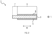
- the electrode 1 has a strip-like shape.
- the electrode 1 comprises a current collector 3 and active material layers 5.
- the current collector 3 has a strip-like shape.
- the active material layers 5 are formed on both sides of the current collector 3 respectively.
- the active material layer formed portion 6 is a portion where an active material layer 5 is formed on a surface of the current collector 3.
- the active material layer unformed portion 7 is a portion where the active material layer 5 is not formed on the surface of the current collector 3.
- the current collector 3 is exposed at the active material layer unformed portion 7.
- the active material layer unformed portion 7 has a strip-like shape extending along a longitudinal direction L of the electrode 1.
- the active material layer unformed portion 7 is situated at an end of the electrode 1 in a width direction W of the electrode 1.
- the current collector 3 is a metal foil of, for example, copper, nickel, stainless steel or the like.
- the current collector 3 may comprise a conductive layer, which mainly comprises a carbon material, formed on the metal foil.
- a thickness of the current collector 3 is, for example, 5 to 50 ⁇ m.
- the active material layer 5 can be prepared by applying a slurry containing, for example, an active material, a binder, and the like onto the current collector 3 and drying the slurry.
- binder examples include a rubber-based binder, such as styrenebutadiene rubber (SBR) or NBR; a fluorine resin, such as polytetrafluoroethylene, or polyvinylidene fluoride; polypropylene, polyethylene, and a fluorine modified (meth) acrylic binder, as disclosed in Japanese Unexamined Patent Application Publication No. 2009-246137 .
- SBR styrenebutadiene rubber
- NBR styrenebutadiene rubber
- fluorine resin such as polytetrafluoroethylene, or polyvinylidene fluoride
- polypropylene polyethylene
- a fluorine modified (meth) acrylic binder as disclosed in Japanese Unexamined Patent Application Publication No. 2009-246137 .
- the slurry may contain other components in addition to the active material and the binder.
- the other components include conductive agents, such as carbon black, graphite, vapor-grown carbon fiber, and metal particles; and thickening agents, such as carboxymethyl cellulose, sodium salt or ammonium salt thereof, methyl cellulose, hydroxymethyl cellulose, ethyl cellulose, hydroxypropyl cellulose, polyvinyl alcohol, oxidized starch, phosphorylated starch, and casein.
- a thickness of the active material layer 5 is not particularly limited.
- the thickness of the active material layer 5 ranges, for example, from 5 to 500 ⁇ m, preferably from 10 to 200 ⁇ m, or more preferably from 10 to 100 ⁇ m.
- the active material contained in the active material layer 5 can be any electrode active materials applicable to a cell or a capacitor that uses insertion/desorption of alkali metal ions.
- the active material may be a negative electrode active material or a positive electrode active material.
- the negative electrode active material is not limited to a particular material.
- the negative electrode active material include carbon materials, such as graphite, easily graphitizable carbon, hardly graphitized carbon, or a composite carbon material composed of graphite particles coated with a carbide of a pitch or resin; and materials containing metals or semimetals that can be alloyed with lithium, such as Si and Sn, or the oxides thereof.
- a specific example of the carbon material is the carbon material described in Japanese Unexamined Patent Application Publication No. 2013-258392 .
- Specific examples of materials containing metals or semimetals that can be alloyed with lithium or oxides thereof are the materials described in Japanese Unexamined Patent Application Publication Nos. 2005-123175 and 2006-107795 .
- the positive electrode active material examples include transition metal oxides, such as cobalt oxide, nickel oxide, manganese oxide, and vanadium oxide; and sulfur active materials, such as elemental sulfur and metal sulfide.
- transition metal oxides such as cobalt oxide, nickel oxide, manganese oxide, and vanadium oxide
- sulfur active materials such as elemental sulfur and metal sulfide.
- the positive electrode active material and the negative electrode active material may each be composed of a single substance or a mixture of two or more substances.
- the active material contained in the active material layer 5 is pre-doped with an alkali metal by using an electrode manufacturing system 11, which will be described later.
- the alkali metal for pre-doping the active material is preferably lithium or sodium, especially lithium.
- a density of the active material layer 5 is preferably 1.30 to 2.00 g/cc, especially 1.40 to 1.90 g/cc.
- the electrode manufacturing system 11 includes an electrolyte solution treatment bath 15, doping baths 17, 19, 21, a cleaning bath 23, conveyor rollers 25, 27, 29, 31, 33, 35, 37, 39, 40, 41, 43, 45, 46, 47, 49, 51, 52, 53, 55, 57, 58, 59, 61, 63, 64, 65, 67, 69, 70, 71, 73, 75, 77, 79, 81, 83, 85, 87, 89, 91, 93 (hereinafter also collectively referred to as a "conveyor roller group”), a supply roll 101, a winding roll 103, supports 105, circulation filtration units 107, six power supplies 109, 110, 111, 112, 113, 114, a tab cleaner 117, a recovery unit 119, and end portion sensors 121.
- a supply roll 101 a winding roll 103
- supports 105 circulation filtration units 107
- the doping baths 17, 19, 21 correspond to a part of the doping unit.
- the conveyor roller group corresponds to a conveyor unit.
- the electrolyte solution treatment bath 15 is a rectangular bath having an opening on an upper side.
- the electrolyte solution treatment bath 15 comprises a bottom surface having a substantially U-shaped section.
- the electrolyte solution treatment bath 15 comprises a partition plate 123.
- the partition plate 123 is supported by a support rod 125 that penetrates an upper end of the partition plate 123.
- the support rod 125 is fixed to a wall or the like (not shown).
- the partition plate 123 extends vertically, and divides an inside of the electrolyte solution treatment bath 15 into two spaces.
- the conveyor roller 33 is attached to a lower end of the partition plate 123.
- the partition plate 123 and the conveyor roller 33 are penetrated and supported by a support rod 127.
- the partition plate 123 comprises a cutout in a vicinity of the lower end to avoid contact with the conveyor roller 33.
- the doping bath 17 comprises an upstream bath 131 and a downstream bath 133.
- the upstream bath 131 is arranged on a supply roll 101 side (hereinafter referred to as an upstream side), and the downstream bath 133 is arranged on a winding roll 103 side (hereinafter referred to as a downstream side).
- the upstream bath 131 is a rectangular bath with an opening on an upper side.
- the upstream bath 131 comprises a bottom surface having a substantially U-shaped section.
- the upstream bath 131 comprises a partition plate 135 and four counter electrode units 137, 139, 141, 143.
- the partition plate 135 is supported by a support rod 145 that penetrates an upper end of the partition plate 135.
- the support rod 145 is fixed to a wall or the like (not shown).
- the partition plate 135 extends vertically, and divides an inside of the upstream bath 131 into two spaces.
- the conveyor roller 40 is attached to a lower end of the partition plate 135.
- the partition plate 135 and the conveyor roller 40 are penetrated and supported by a support rod 147.
- the partition plate 135 comprises a cutout in a vicinity of the lower end to avoid contact with the conveyor roller 40. There is a space between the conveyor roller 40 and the bottom surface of the upstream bath 131.
- the counter electrode unit 137 is arranged in an upstream portion of the upstream bath 131.
- the counter electrode units 139, 141 are arranged so as to hold the partition plate 135 from both sides.
- the counter electrode unit 143 is arranged in a downstream portion of the upstream bath 131.
- the counter electrode units 137, 139, 141, 143 are connected to a terminal 109B of a power supply 109.
- the counter electrode units 137, 139, 141, 143 have similar configurations. Herein, descriptions will be given of configurations of the counter electrode units 137, 139 with reference to FIG. 5 .
- the counter electrode units 137, 139 each have a structure, in which a conductive base material 153, an alkali metal-containing plate 155, and a porous insulating member 157 are stacked.
- a material for the conductive base material 153 include copper, stainless steel, and nickel.
- the alkali metal-containing plate 155 is not limited to a specific form, and may be, for example, an alkali metal plate, or an alkali metal alloy plate.
- the alkali metal-containing plate 155 may have a thickness of, for example, 0.03 to 6 mm.
- the porous insulating member 157 has a plate shape.
- the porous insulating member 157 is stacked on the alkali metal-containing plate 155.
- the plate shape of the porous insulating member 157 is a shape in a state where the porous insulating member 157 is stacked on the alkali metal-containing plate 155.
- the porous insulating member 157 may be a member that maintains a certain shape by itself or may be a member that can easily change its form, such as a net.
- the porous insulating member 157 is porous. Thus, a dope solution described later can pass through the porous insulating member 157. This allows the alkali metal-containing plate 155 to come into contact with the dope solution.
- Examples of the porous insulating member 157 may include a mesh made of resin or the like.
- Examples of the resin include polyethylene, polypropylene, nylon, polyetheretherketone, and polytetrafluoroethylene.
- An opening of the mesh may be appropriately specified, and may be, for example, in a range of 0.1 ⁇ m to 10 mm, and preferably in a range of 0.1 to 5 mm.
- a thickness of the mesh may be appropriately specified, and may be, for example, in a range of 1 ⁇ m to 10 mm, and preferably in a range of 30 ⁇ m to 1 mm.
- a percentage of open area of the mesh may be appropriately specified, and may be, for example, in a range of 5 to 98%, preferably in a range of 5 to 95%, and more preferably in a range of 50 to 95%
- the porous insulating member 157 may be entirely made from an insulating material or may partially comprise an insulating layer.
- the downstream bath 133 has a configuration basically similar to that of the upstream bath 131. There is the conveyor roller 46 instead of the conveyor roller 40 inside the downstream bath 133.
- the counter electrode units 137, 139, 141, 143 provided in the downstream bath 133 are connected to one electrode of the power supply 110.
- the doping bath 19 has a configuration basically similar to that of the doping bath 17. There are the conveyor rollers 52, 58 instead of the conveyor rollers 40, 46 inside the doping bath 19.
- the counter electrode units 137, 139, 141, 143 provided in the upstream bath 131 of the doping bath 19 are connected to one electrode of the power supply 111.
- the counter electrode units 137, 139, 141, 143 provided in the downstream bath 133 of the doping bath 19 are connected to one electrode of the power supply 112.
- the doping bath 21 has a configuration basically similar to that of the doping bath 17. There are the conveyor rollers 64, 70 instead of the conveyor rollers 40, 46 inside the doping bath 21.
- the counter electrode units 137, 139, 141, 143 provided in the upstream bath 131 of the doping bath 21 are connected to one electrode of the power supply 113.
- the counter electrode units 137, 139, 141, 143 provided in the downstream bath 133 of the doping bath 21 are connected to one electrode of the power supply 114.
- the cleaning bath 23 has a configuration basically similar to that of the electrolyte solution treatment bath 15. There is the conveyor roller 75 instead of the conveyor roller 33 inside the cleaning bath 23.
- the conveyor rollers 37, 39, 43, 45, 49, 51, 55, 57, 61, 63, 67, 69 in the conveyor roller group are made from an electrically conductive material.
- Other conveyor rollers in the conveyor roller group are made from an elastomer except for bearing portions thereof.
- the conveyor roller group conveys the electrode 1 along a specified path. The path along which the conveyor roller group conveys the electrode 1 runs from the supply roll 101 to the winding roll 103, sequentially through the inside of the electrolyte solution treatment bath 15, the inside of the doping bath 17, the inside of the doping bath 19, the inside of the doping bath 21, the inside of the cleaning bath 23, and the inside of the tab cleaner 117 in this order.
- a part of the path passing through the inside of the electrolyte solution treatment bath 15 first runs downward through the conveyor rollers 29, 31, and then is turned upward by the conveyor roller 33.
- a part of the above-described path passing through the inside of the doping bath 17 is as follows.
- the part is first turned downward by the conveyor roller 37, and runs downward in the space 149 in the upstream bath 131.
- the part is turned upward by the conveyor roller 40, and runs upward in the space 151 in the upstream bath 131.
- the part of the path is turned downward by the conveyor rollers 41, 43, and runs downward in the space 149 in the downstream bath 133.
- the part is turned upward by the conveyor roller 46, and runs upward in the space 151 in the downstream bath 133.
- the part of the path lastly is turned to run horizontally by the conveyor roller 47, and runs toward the doping bath 19.
- a part of the above-described path passing through the inside of the doping bath 19 is as follows.
- the part is first turned downward by the conveyor roller 49, and runs downward in the space 149 in the upstream bath 131.
- the part is turned upward by the conveyor roller 52, and runs upward in the space 151 in the upstream bath 131.
- the part of the path is turned downward by the conveyor rollers 53, 55, and runs downward in the space 149 in the downstream bath 133.
- the part is turned upward by the conveyor roller 58, and runs upward in the space 151 in the downstream bath 133.
- the part of the path lastly is turned to run horizontally by the conveyor roller 59, and runs toward the doping bath 21.
- a part of the above-described path passing through the inside of the doping bath 21 is as follows.
- the part is first turned downward by the conveyor roller 61, and runs downward in the space 149 in the upstream bath 131. Then the part is turned upward by the conveyor roller 64, and runs upward in the space 151 in the upstream bath 131. Subsequently, the part of the path is turned downward by the conveyor rollers 65, 67, and runs downward in the space 149 in the downstream bath 133. Then the part is turned upward by the conveyor roller 70, and runs upward in the space 151 in the downstream bath 133. The part of the path lastly is turned to run horizontally by the conveyor roller 71, and runs toward the cleaning bath 23.
- the electrode 1 is wound around the supply roll 101. Specifically, the supply roll 101 retains the electrode 1 in a wound-up state.
- the active material of the electrode 1 retained by the supply roll 101 is not yet doped with an alkali metal.
- the conveyor roller group draws the electrode 1 retained around the supply roll 101, and conveys the electrode 1.
- the winding roll 103 winds up the electrode 1 conveyed by the conveyor roller group, and stores the electrode 1.
- the electrode 1 stored around the winding roll 103 has been subjected to a pre-doping process in the doping baths 17, 19, 21.
- the active material of the electrode 1 stored around the winding roll 103 has been doped with an alkali metal.
- the supports 105 support the electrolyte solution treatment bath 15, the doping baths 17, 19, 21, and the cleaning bath 23 from below.
- the supports 105 are changeable in height.
- the circulation filtration unit 107 is provided in each of the doping baths 17, 19, 21.
- the circulation filtration unit 107 comprises a filter 161, a pump 163, and a pipe 165.
- the pipe 165 is a circulation pipe that extends from the doping bath 17, sequentially passes through the pump 163 and the filter 161, and then returns to the doping bath 17.
- the dope solution in the doping bath 17 is circulated through the pipe 165 and the filter 161 by a driving force of the pump 163, and is returned to the doping bath 17.
- foreign matters and the like in the dope solution are filtered by the filter 161.
- the foreign matters include foreign matters precipitated from the dope solution and foreign matters produced from the electrode 1.
- a material for the filter 161 may include resin, such as polypropylene and polytetrafluoroethylene.
- a pore size of the filter 161 may be appropriately specified, and may be in a range of, for example, 0.2 ⁇ m to 50 ⁇ m.
- the circulation filtration units 107 provided in the doping baths 19, 21 each also have a configuration, action and effects similar to those of the above-described circulation filtration unit 107.
- illustration of the dope solution is omitted for the purpose of convenience.
- a terminal 109A of the power supply 109 is connected to the conveyor rollers 37, 39.
- the terminal 109B of the power supply 109 is connected to the counter electrode units 137, 139, 141, 143 provided in the upstream bath 131 of the doping bath 17.
- the electrode 1 comes into contact with the conveyor rollers 37, 39.
- the electrode 1 and the counter electrode units 137, 139, 141, 143 are disposed in the dope solution, which is an electrolyte solution.
- the electrode 1 and the counter electrode units 137, 139, 141, 143 are electrically connected with each other through the electrolyte solution in the upstream bath 131 of the doping bath 17.
- a terminal 110A of the power supply 110 is connected to the conveyor rollers 43, 45.
- a terminal 110B of the power supply 110 is connected to the counter electrode units 137, 139, 141, 143 provided in the downstream bath 133 of the doping bath 17.
- the electrode 1 comes into contact with the conveyor rollers 43, 45.
- the electrode 1 and the counter electrode units 137, 139, 141, 143 are disposed in the dope solution, which is an electrolyte solution.
- the electrode 1 and the counter electrode units 137, 139, 141, 143 are electrically connected with each other through the electrolyte solution in the downstream bath 133 of the doping bath 17.
- One terminal of the power supply 111 is connected to the conveyor rollers 49, 51.
- the other terminal of the power supply 111 is connected to the counter electrode units 137, 139, 141, 143 provided in the upstream bath 131 of the doping bath 19.
- the electrode 1 comes into contact with the conveyor rollers 49, 51.
- the electrode 1 and the counter electrode units 137, 139, 141, 143 are disposed in the dope solution, which is an electrolyte solution.
- the electrode 1 and the counter electrode units 137, 139, 141, 143 are electrically connected with each other through the electrolyte solution in the upstream bath 131 of the doping bath 19.
- One terminal of the power supply 112 is connected to the conveyor rollers 55, 57.
- the other terminal of the power supply 112 is connected to the counter electrode units 137, 139, 141, 143 provided in the downstream bath 133 of the doping bath 19.
- the electrode 1 comes into contact with the conveyor rollers 55, 57.
- the electrode 1 and the counter electrode units 137, 139, 141, 143 are disposed in the dope solution, which is an electrolyte solution.
- the electrode 1 and the counter electrode units 137, 139, 141, 143 are electrically connected with each other through the electrolyte solution in the downstream bath 133 of the doping bath 19.
- One terminal the power supply 113 is connected to the conveyor rollers 61, 63.
- the other terminal of the power supply 113 is connected to the counter electrode units 137, 139, 141, 143 provided in the upstream bath 131 of the doping bath 21.
- the electrode 1 comes into contact with the conveyor rollers 61, 63.
- the electrode 1 and the counter electrode units 137, 139, 141, 143 are disposed in the dope solution, which is an electrolyte solution.
- the electrode 1 and the counter electrode units 137, 139, 141, 143 are electrically connected with each other through the electrolyte solution in the upstream bath 131 of the doping bath 21.
- One terminal of the power supply 114 is connected to the conveyor rollers 67, 69.
- the other terminal of the power supply 114 is connected to the counter electrode units 137, 139, 141, 143 provided in the downstream bath 133 of the doping bath 21.
- the electrode 1 comes into contact with the conveyor rollers 67, 69.
- the electrode 1 and the counter electrode units 137, 139, 141, 143 are disposed in the dope solution, which is an electrolyte solution.
- the electrode 1 and the counter electrode units 137, 139, 141, 143 are electrically connected with each other through the electrolyte solution in the downstream bath 133 of the doping bath 21.
- the tab cleaner 117 cleans the active material layer unformed portion 7 of the electrode 1.
- a configuration of the tab cleaner 117 will be detailed later.
- the recovery unit 119 is arranged in each of the electrolyte solution treatment bath 15, the doping baths 17, 19, 21, and the cleaning bath 23. The recovery unit 119 collects the solution that the electrode 1 carries away from the bath, and returns the solution to the bath.
- the end portion sensor 121 detects a position of an end portion of the electrode 1 in a width direction W of the electrode 1. Based on the detection result of the end portion sensor 121, an end position adjuster unit 241, which will be described later, adjusts positions of the supply roll 101 and the winding roll 103 in the width direction W.
- the tab cleaner 117 corresponds to a cleaning unit. As shown in FIG. 6 , the tab cleaner 117 comprises: cleaning roller units 201, 203; a cleaning liquid tank 205; a pump 207; a dryer unit 209; an overflow pipe 248; and a waste liquid tank 250.
- the cleaning roller unit 201 is disposed between the conveyor roller 79 and the conveyor roller 81.
- the cleaning roller unit 201 comprises a first portion 211, and a second portion 213.
- the first portion 211 and the second portion 213 are arranged so as to hold the electrode 1 from both sides.
- the first portion 211 comprises: a support plate 215; a brush roller 217; a cleaning tank 219; and a motor 221.
- the brush roller 217 corresponds to a cleaning roller.
- the cleaning tank 219 corresponds to a tab cleaning tank.
- the first portion 211 comprises: a pulley 223; a pulley 225; and a shaft 227. Illustrations of the pulley 223 and the pulley 225 are omitted in FIG. 6 for the purpose of convenience.
- the support plate 215 is a plate-shaped member.
- the brush roller 217 is attached to the shaft 227.
- An outer peripheral portion of the brush roller 217 is formed of brush.
- a hardness of the brush roller 217 specified by JIS S 3016-1995 is generally in a range of 1 N/cm 2 to 1000 N/cm 2 , preferably in a range of 5 N/cm 2 to 500 N/cm 2 , more preferably in a range of 10 N/cm 2 to 300 N/cm 2 , and particularly preferably in a range of 20 N/cm 2 to 100 N/cm 2 .
- the hardness of the brush roller 217 means a hardness of the brush situated on the outer peripheral portion.
- Examples of a brush material having such a hardness include plastic, and animal fiber.
- the brush material is a material for the brush roller 217.
- Examples of the plastic include polyethylene, polypropylene, polyvinyl chloride, polyethylene terephthalate, polybutylene terephthalate, acrylic, nylon, polycarbonate, polyphenylene sulfide, polyetheretherketone, and polytetrafluoroethylene.
- Examples of the animal fiber include horsehair, swine hair, and goat hair.
- the shaft 227 is pivotably supported by a bearing 229 that is provided to the support plate 215. Axial directions of the shaft 227 and the brush roller 217 are parallel to the width direction W of the electrode 1.
- the brush roller 217 is employed as the cleaning roller.
- a sponge roller may be employed as the cleaning roller.
- a hardness of the sponge roller as measured with a type E durometer specified by JIS K 6253-3 is preferably in a range of 1 to 40.
- Examples of the sponge material having such a hardness include elastomer.
- the sponge material denotes a material of the sponge roller.
- Examples of the elastomer include polyolefin rubber, styrene rubber, styrene butadiene rubber, polyurethane, chloroprene rubber, ethylene propylene diene rubber, nitrile rubber, silicone rubber, fluororubber, and polyvinyl alcohol.
- the cleaning tank 219 is fixed to the support plate 215 under the brush roller 217.
- the cleaning tank 219 stores the cleaning liquid.
- the cleaning liquid stored in the cleaning tank 219 is, for example, a carbonate-based solvent.
- Examples of the carbonate-based solvent include, dimethyl carbonate, ethyl methyl carbonate, and diethyl carbonate.
- the cleaning tank 219 is open on an upper side. A part of a lower side of the brush roller 217 gets into the cleaning tank 219, and is immersed in the cleaning liquid.
- the motor 221 is attached to the support plate 215.
- the pulley 223 is attached to the motor 221.
- the pulley 225 is attached to the shaft 227.
- the second portion 213 basically has a configuration that is laterally reversed with respect to the first portion 211 in FIG. 6 . However, the second portion 213 does not comprise the motor 221. As shown in FIG. 7 , a pulley 231 is attached to the shaft 227 of the second portion 213.
- the first portion 211 and the second portion 213 each are movable between a position close to the electrode 1 (hereinafter to be referred to as a close position) and a position distanced from the electrode 1 (hereinafter to be referred to as a distanced position).
- a close position a position close to the electrode 1
- a distanced position a position distanced from the electrode 1
- the first portion 211 and the second portion 213 are positioned at the close positions.
- the brush roller 217 of the first portion 211 and the brush roller 217 of the second portion 213 each come into contact with the active material layer unformed portion 7 of the electrode 1.
- Neither the brush roller 217 of the first portion 211 nor the brush roller 217 of the second portion 213 comes into contact with the active material layer formed portion 6.
- the first portion 211 and the second portion 213 are at the distanced positions, neither the brush roller 217 of the first portion 211 nor the brush roller 217 of the second portion 213 comes into contact with any part of the electrode 1.
- the electrode 1 is passed through the electrode manufacturing system 11, the first portion 211 and the second portion 213 are set at the distanced positions.
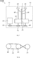
- a belt 233 is looped around the pulley 223, the pulley 225, and the pulley 231.
- the belt 233 is looped in the shape of the number eight across the pulley 225 and the pulley 231.
- the motor 221 rotates clockwise
- the pulley 225 and the brush roller 217 of the first portion 211 also rotate clockwise.
- the pulley 231 and the brush roller 217 of the second portion 213 rotate counterclockwise. That is, the brush roller 217 of the first portion 211 and the brush roller 217 of the second portion 213 rotate in opposite directions.
- the cleaning roller unit 203 is arranged between the conveyor roller 83 and the conveyor roller 85.
- the cleaning roller unit 203 has a configuration similar to that of the cleaning roller unit 201.
- the cleaning liquid tank 205 stores the cleaning liquid.
- the cleaning liquid tank 205 communicates with the cleaning tanks 219 of the cleaning roller units 201, 203 via the pump 207 and a pipe 235.
- An operation of the pump 207 gradually replaces the cleaning liquid in the cleaning tanks 219 of the cleaning roller units 201, 203 with the cleaning liquid in the cleaning liquid tank 205. That is, the pump 207 supplies the cleaning liquid to the cleaning tanks 219 of the cleaning roller units 201, 203.
- the cleaning liquid tank 205, the pump 207, and the pipe 235 correspond to a cleaning liquid supplier unit.
- the dryer unit 209 is arranged between the cleaning roller unit 203 and the conveyor roller 85.
- the dryer unit 209 comprises a plurality of blow nozzles 237.
- the plurality of blow nozzles 237 blow nitrogen, which has a dew point of -40 deg. C or lower, to the electrode 1, to dry the electrode 1.
- the overflow pipe 248 drains the cleaning liquid overflown from the cleaning tanks 219 to the waste liquid tank 250.
- the waste liquid tank 250 stores the cleaning liquid flown down through the overflow pipe 248.
- the electrode manufacturing system 11 comprises a control system 239 shown in FIG. 9 .
- the control system 239 comprises the end position adjuster unit 241, two end portion sensors 121, and a roll driving unit 243. As shown in FIG. 3 , one of the two end portion sensors 121 is disposed near the supply roll 101. The other one of the two end portion sensors 121 is disposed near the winding roll 103.
- the end position adjuster unit 241 is a computer including a CPU, a memory, and the like.
- the roll driving unit 243 is capable of changing positions of the supply roll 101 and the winding roll 103 in the width direction W. If the positions of the supply roll 101 and the winding roll 103 in the width direction W change, the position of the electrode 1 in the width direction W changes.
- the end position adjuster unit 241 uses the end portion sensors 121 to detect end positions of the electrode 1 in the width direction W near the supply roll 101 and near the winding roll 103. Based on the detection result, the end position adjuster unit 241 adjusts positions of the supply roll 101 and the winding roll 103 in the width direction W using the roll driving unit 243.
- the supply roll 101 and the winding roll 103 after the adjustment are situated at positions where the brush roller 217 is in contact with the active material layer unformed portion 7, and is not in contact with the active material layer formed portion 6.
- the dope solution is stored in the electrolyte solution treatment bath 15, and the doping baths 17, 19, 21.
- the dope solution contains alkali metal ions and solvent.
- the dope solution is an electrolyte solution.
- the solvent may include an organic solvent.
- the organic solvent is preferably an aprotic organic solvent.
- the aprotic organic solvent include ethylene carbonate, propylene carbonate, butylene carbonate, dimethyl carbonate, diethyl carbonate, methyl ethyl carbonate, 1-fluoroethylene carbonate, ⁇ -butyrolactone, acetonitrile, dimethoxyethane, tetrahydrofuran, dioxolane, methylene chloride, sulfolane, diethylene glycol dimethyl ether (diglyme), diethylene glycol methyl ethyl ether, triethylene glycol dimethyl ether (triglyme), triethylene glycol butyl methyl ether, and tetraethylene glycol dimethyl ether (tetraglyme).
- organic solvent ionic liquids of a quaternary imidazolium salt, quaternary pyridinium salt, quaternary pyrrolidinium salt, quaternary piperidinium salt, and the like, may be used.
- the organic solvent may be made of a single component, or may be a mixed solvent of two or more types of components.
- the organic solvent may be made of a single component, or may be a mixed solvent of two or more types of components.
- the alkali metal ions included in the dope solution form an alkali metal salt.
- the alkali metal salt is preferably a lithium salt or a sodium salt.
- Examples of an anionic moiety forming the alkali metal salt may include phosphorus anion having a fluoro group, such as PF 6 - , PF 3 (C 2 F 5 ) 3 - , and PF 3 (CF 3 ) 3 - ; boron anion having a fluoro group or a cyano group, such as BF 4 - , BF 2 (CF) 2 - , BF 3 (CF 3 ) - , and B(CN) 4 - ; sulfonyl imide anion having a fluoro group, such as N(FSO 2 ) 2 - , N(CF 3 SO 2 ) 2 - , and N(C 2 F 5 SO 2 ) 2 - ; and organic sulfonic acid anion having a fluoro group,
- a concentration of the alkali metal salt in the dope solution is preferably 0.1 mol/L or more, and more preferably within a range of 0.5 to 1.5 mol/L. With the concentration of the alkali metal salt within this range, pre-doping of alkali metal proceeds efficiently.
- the dope solution may further comprise additives, such as vinylene carbonate, vinylethylene carbonate, 1-fluoroethylene carbonate, 1-(trifluoromethyl) ethylene carbonate, succinic anhydride, maleic anhydride, propane sultone, and diethyl sulfone.
- additives such as vinylene carbonate, vinylethylene carbonate, 1-fluoroethylene carbonate, 1-(trifluoromethyl) ethylene carbonate, succinic anhydride, maleic anhydride, propane sultone, and diethyl sulfone.
- the dope solution may further comprise a flame retardant, such as a phosphazene compound.
- a flame retardant such as a phosphazene compound.
- an added amount of the flame retardant is preferably 1 part by mass or more, more preferably 3 parts by mass or more, and further preferably 5 parts by mass or more, with respect to 100 parts by mass of the dope solution.
- the added amount of the flame retardant is preferably 20 parts by mass or less, more preferably 15 parts by mass or less, and further preferably 10 parts by mass or less, with respect to 100 parts by mass of the dope solution.
- a method for manufacturing the pre-doped electrode 1 is as follows.
- the electrode 1 before pre-doping is wound around the supply roll 101.
- the electrode 1 before pre-doping is drawn out from the supply roll 101, and is passed along the above-described path to the winding roll 103.
- the first portion 211 and the second portion 213 that form each of the cleaning roller units 201, 203 of the tab cleaner 117 are positioned at the distanced positions.
- the electrolyte solution treatment bath 15, the doping baths 17, 19, 21, and the cleaning bath 23 are raised and set at specified positions shown in FIG. 3 .
- the dope solution is stored in the electrolyte solution treatment bath 15, and the doping baths 17, 19, 21.
- the dope solution is as described in "4. Composition of Dope Solution”.
- the cleaning liquid is stored in the cleaning bath 23.
- the cleaning liquid stored in the cleaning bath 23 is an organic solvent. Examples of the organic solvent include dimethyl carbonate, ethyl methyl carbonate, and diethyl carbonate.
- the first portion 211 and the second portion 213, which form each of the cleaning roller units 201, 203 of the tab cleaner 117, are positioned at the close positions.
- the conveyor roller group conveys the electrode 1 from the supply roll 101 to the winding roll 103 along the above-described path.
- the path for conveying the electrode 1 passes through the insides of the doping baths 17, 19, 21. While the electrode 1 passes through the insides of the doping baths 17, 19, 21, the active material contained in the active material layer 5 is pre-doped with an alkali metal.
- the conveyor roller group further conveys the electrode 1 to the cleaning bath 23.
- the electrode 1 is cleaned in the cleaning bath 23 while being conveyed by the conveyor roller group.
- the conveyor roller group continuously conveys the electrode 1 to the tab cleaner 117. A part of the electrode 1 conveyed to the tab cleaner 117 has been already subjected to the pre-doping process.
- the cleaning roller units 201, 203 of the tab cleaner 117 each clean the active material layer unformed portion 7 of the electrode 1.
- An area to be cleaned is the active material layer unformed portion 7 that is adjacent to the active material layer formed portion 6, which has been already subjected to the pre-doping process. Being adjacent means, for example, being adjacent in the width direction W.
- the cleaning performed by the cleaning roller units 201, 203 is as follows. The cleaning means to remove at least a part of the dope solution from at least the active material layer unformed portion 7.
- the brush roller 217 of the first portion 211 and the brush roller 217 of the second portion 213 each come into contact with the active material layer unformed portion 7 while rotating.
- the brush roller 217 of the first portion 211 and the brush roller 217 of the second portion 213 each are immersed in the cleaning liquid in the cleaning tank 219. Thus, they come into contact with the active material layer unformed portion 7 while containing the cleaning liquid. Consequently, the active material layer unformed portion 7 is cleaned.
- a peripheral speed of the brush roller 217 at a part coming into contact with the electrode 1 will be referred to as V1.
- a conveying speed of the electrode 1 will be referred to as V2.
- V2 is a positive value.
- V1 has the same unit as V2.
- V1 takes a positive value.
- V1 takes a negative value.
- a ratio of V1 to V2 is expressed as a ratio V1/V2.
- the ratio V1/V2 is a value obtained by dividing V1 by V2.
- the ratio V1/V2 is preferably in a range of -5.0 to 0.99, or in a range of 1.01 to 5.0 from a viewpoint of effectively cleaning the active material layer unformed portion 7 as well as steadily conveying the electrode 1.
- the ratio V1/V2 is more preferably in a range of 0.01 to 0.95, or in a range of 1.05 to 3.0.
- the ratio V1/V2 is much more preferably in a range of 0.1 to 0.9, or in a range of 1.1 to 2.0.
- the ratio V1/V2 is preferably not 0.
- the dryer unit 209 of the tab cleaner 117 dries the electrode 1 having passed through the cleaning roller units 201, 203. Then the electrode 1 is wound by the winding roll 103.
- the electrode 1 may be a positive electrode or a negative electrode.
- a positive electrode active material is doped with an alkali metal using the electrode manufacturing system 11
- a negative electrode active material is doped with an alkali metal using the electrode manufacturing system 11.
- a doping amount of the alkali metal is preferably 70 to 95% with respect to a theoretical capacity of the negative electrode active material.
- the doping amount is preferably 10 to 30% with respect to a theoretical capacity of the negative electrode active material.
- the ratio V1/V2 is within a range of -5.0 to 0.99, or within a range of 1.01 to 5.0, or more particularly within a range of 0.01 to 0.95, or within a range of 1.05 to 3.0, it is possible to achieve the above-described effect and also to reduce damages to or breakages of the current collector 3 or the like due to biting of the brush rollers 217 with each other. Consequently, the active material layer unformed portion 7 can be cleaned more stably.
- a mechanism shown in FIG. 7 rotates the brush roller 217 of each of the cleaning roller units 201, 203.
- a mechanism shown in FIG. 10 rotates the brush roller 217 of each of the cleaning roller units 201, 203.
- a gear 245 and a compact motor 247 are attached to the shaft 227 of the first portion 211.
- the compact motor 247 is fixed.
- the shaft 227, the brush roller 217, and the gear 245 are rotated by a driving force of the compact motor 247.
- a gear 249 is attached to the shaft 227 of the second portion 213.
- the gear 249 meshes with the gear 245. If the gear 245 rotates, the gear 249, and the shaft 227 and the brush roller 217 of the second portion 213 also rotate.
- the brush roller 217 of the first portion 211 and the brush roller 217 of the second portion 213 are rotated by the driving force of the compact motor 247.
- a rotating direction of the brush roller 217 of the first portion 211 is opposite to a rotating direction of the brush roller 217 of the second portion 213.
- the tab cleaner 117 comprises the cleaning roller units 201, 203 shown in FIG. 6 and FIG. 7 .
- a cleaning roller unit 301 shown in FIG. 11 and FIG. 12 is provided instead of the cleaning roller units 201, 203.
- the cleaning roller unit 301 is arranged at the position of each of the cleaning roller units 201, 203 of the first embodiment.
- the cleaning roller unit 301 comprises a first portion 311 and a second portion 313.
- the first portion 311 and the second portion 313 are arranged so as to hold the electrode 1 from both sides.
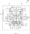
- the first portion 311 comprises a brush arm 315, a supporting shaft 317, a fixed portion 318, a brush roller 217, a brush shaft 319, and a motor 321.
- the brush arm 315 is attached rotatably about the supporting shaft 317.
- the brush arm 315 comprises a greaseless bearing 323 at a portion, to which the supporting shaft 317 is attached.
- the brush arm 315 comprises a main body 325, a first projection 327, a second projection 329, a third projection 331, and a fourth projection 333.
- the main body 325 is a portion through which the supporting shaft 317 runs. As shown in FIG. 12 , the first projection 327, the second projection 329, and the third projection 331 project toward the electrode 1 more than the main body 325 does. The first projection 327, the second projection 329, and the third projection 331 are aligned to be spaced apart from each other along the width direction W. The fourth projection 333 projects from the main body 325 in a direction opposite from the electrode 1.
- the supporting shaft 317 and the fixed portion 318 each are fixed to a frame of the electrode manufacturing system 11.
- the fixed portion 318 may be a part of the frame of the electrode manufacturing system 11.
- the supporting shaft 317 and the fixed portion 318 are situated at positions fixed with respect to the conveyor roller group.
- An axial direction of the supporting shaft 317 is parallel to the width direction W.
- the fourth projection 333 is fixed to the fixed portion 318 with a fixing screw 335. Thus, a position of the brush arm 315 is fixed.
- the brush shaft 319 is rotatably supported by the first projection 327 and the second projection 329.
- Each of the first projection 327 and the second projection 329 comprises a greaseless bearing 323 at a portion to which the brush shaft 319 is attached.
- An axial direction of the brush shaft 319 is parallel to the width direction W.
- the brush roller 217 is pivotally supported by the brush shaft 319.
- the brush roller 217 comes into contact with the active material layer unformed portion 7.
- the brush roller 217 does not come into contact with the active material layer formed portion 6.
- the brush arm 315 is adjustable in position along the width direction W. The position of the brush roller 217 along the width direction W can be adjusted by adjusting the position of the brush arm 315 along the width direction W.
- the motor 321 is arranged between the second projection 329 and the third projection 331.
- the motor 321 drives the brush shaft 319 and the brush roller 217 to rotate.
- the second portion 313 basically has a configuration that is laterally reversed with respect to the first portion 311 in FIG. 11 and FIG. 12 . However, the second portion 313 does not comprise the fixed portion 318.
- the brush arm 315 of the second portion 313 is rotatable about the supporting shaft 317.
- a weight 337 is hanged from the fourth projection 333 of the second portion 313.
- the brush arm 315 of the second portion 313 is biased in a direction for pressing the brush roller 217 against the electrode 1.
- a long strip-shaped current collector 3 was prepared.
- the current collector 3 was a negative electrode current collector. Dimensions of the current collector 3 were: 150 mm in width; 100 m in length; and 8 ⁇ m in thickness. A surface roughness Ra of the current collector 3 was 0.1 ⁇ m.
- the current collector 3 was formed of copper foil. Negative electrode active material layers 5 were formed on both sides of the current collector 3.
- a coating amount of the negative electrode active material layer 5 formed on one side of the current collector 3 was 50 g/m 2 .
- the negative electrode active material layer 5 was formed along a longitudinal direction of the current collector 3.
- the negative electrode active material layer 5 was formed over a width of 130 mm from an end of the current collector 3 in the width direction W.
- a negative electrode active material layer unformed portion at the other end of the current collector 3 in the width direction W had a width of 20 mm.
- the negative electrode active material layer unformed portion is a portion where the negative electrode active material layer 5 is not formed. Then drying and pressing were performed, whereby the electrode 1 was obtained.
- the negative electrode active material layer 5 contained a negative electrode active material, carboxymethyl cellulose, acetylene black, a binder and a dispersant at a mass ratio of 88:3:5:3:1.
- the negative electrode active material was a mixture of a silicon-based active material and a graphite-based active material.
- the negative electrode active material contained the silicon-based active material and the graphite-based active material at a mass ratio of 2:8.
- the acetylene black corresponds to a conductive agent.
- the electrode manufacturing system 11 shown in FIG. 3 was prepared and then the electrode 1 was fed through the electrode manufacturing system 11.
- the doping baths 17, 19, 21 each were provided with the counter electrode units 139, 141, 143.
- Then the dope solution was supplied into the doping baths 17, 19, 21.
- the dope solution contained 1.4 M of LiPF 6 .
- the solvent of the dope solution was a mixed liquid including ethylene carbonate (EC), ethyl methyl carbonate (EMC), and dimethyl carbonate (DMC) at a volume ratio of 1:1:1.
- the electrode 1 fed through the electrode manufacturing system 11 and the counter electrode units 139, 141, 143 were connected to a direct current power source having a current/voltage monitor, and a current of 5A was conducted while the electrode 1 was conveyed at a speed of 0.1 m/min.
- the center of the negative electrode active material layer 95 of the electrode 1 in the width direction W coincided with the center of the lithium metal plate of the counter electrode unit 51 in the width direction W.
- An energization time was set, in consideration of the irreversible capacity, to a time in which a ratio of lithium doping in the negative electrode active material layer 5 became 15% of a discharge capacity C2 of the negative electrode.
- the irreversible capacity was estimated in advance by measuring the discharge capacity of the electrode 1 having been doped with the lithium. Through this process, the negative electrode active material in the negative electrode active material layer 95 was doped with the lithium, whereby the electrode 1 became a pre-doped negative electrode.
- the electrode 1 is a negative electrode for a lithium-ion rechargeable battery.
- the electrode 1 was passed through the cleaning bath 23, and then was wound. Dimethyl carbonate (DMC) at 25 degrees C was stored in the cleaning bath 23. In this way, the pre-doped electrode 1 was manufactured.
- DMC Dimethyl carbonate
- the electrode 1 manufactured as above was again fed through the electrode manufacturing system 11 of the third embodiment.
- a brush roller made from polypropylene with a wire diameter of 0.1 mm was used as the brush roller 217.
- a hardness of the brush roller specified by JIS S 3016-1995 was 40 N/cm 2 .
- the weight 337 weighed 300g.
- the dope solution was supplied into the doping baths 17, 19, 21.
- the electrode 1 was cleaned using the tab cleaner 117 while the electrode 1 was conveyed at a speed of 1.0 m/min.
- the peripheral speed V1 of the brush roller 217 was 0.79 m/min.
- the ratio V1/V2 was 0.79.
- Example 1 the ratio V1/V2 was smaller than 1. Owing to that, the active material layer unformed portion 7 was sufficiently cleaned and the tab portion was excellently welded.
- Example 2 Basically, procedures similar to those in Example 1 were performed. However, the peripheral speed V1 of the brush roller 217 was 1.0 m/min. The ratio V1/V2 was 1. The active material layer unformed portion 7 was cleaned. However, a certain amount of sputtering of copper occurred during laser-welding. There were blowholes observed in a part of the welded area.
- Example 2 the ratio V1/V2 was 1. Owing to that, the active material layer unformed portion 7 in Example 1 was cleaned more sufficiently than Example 2.
- Example 2 Basically, procedures similar to those in Example 1 were performed. However, the peripheral speed V1 of the brush roller 217 was 1.18 m/min. The ratio V1/V2 was 1.18. Sputtering of copper did not occur during laser-welding. There was no blowhole observed in the welded area.
- Example 3 the ratio V1/V2 was greater than 1. Owing to that, the active material layer unformed portion 7 was sufficiently cleaned, and the tab portion was excellently welded.
- Example 2 Basically, procedures similar to those in Example 1 were performed. However, the peripheral speed V1 of the brush roller 217 was 1.57 m/min. The ratio V1/V2 was 1.57. Sputtering of copper did not occur during laser-welding. There was no blowhole observed at the welded area.
- Example 4 the ratio V1/V2 was greater than 1. Owing to that, the active material layer unformed portion 7 was sufficiently cleaned, and the tab portion was excellently welded.
- Example 1 Basically, procedures similar to those in Example 1 were performed. However, the peripheral speed V 1 of the brush roller 217 was 2.36 m/min. The ratio V1/V2 was 2.36. The active material layer unformed portion 7 was cleaned. However, the electrode 1 was wrinkled because the brush rollers 217 easily bit into each other, resulting in deviation of the active material layer unformed portion 7 from the right position. This caused an unsteady conveyance of the electrode 1. Consequently, the active material layer unformed portion 7 in Example 1 was cleaned more sufficiently than that in Example 5.
- Example 2 Basically, procedures similar to those in Example 1 were performed. However, the peripheral speed V1 of the brush roller 217 was 4.71 m/min. The conveying speed V2 of the electrode 1 was 3.0 m/min. The ratio V1/V2 was 1.57. Sputtering of copper did not occur during laser-welding. There was no blowhole observed in the welded area.
- Example 6 although the conveying speed V2 was high, the ratio V1/V2 was set within an appropriate range, whereby the active material layer unformed portion 7 was sufficiently cleaned and the tab portion was excellently welded.
- Example 2 Basically, procedures similar to those in Example 1 were performed. However, the peripheral speed V1 of the brush roller 217 was -0.39 m/min. The conveying speed V2 of the electrode 1 was 1.0 m/min. The ratio V1/V2 was - 0.39.
- Example 1 The active material layer unformed portion 7 was cleaned. However, the electrode 1 was wrinkled because the brush rollers 217 easily bit into each other, resulting in deviation of the active material layer unformed portion 7 from the right position. This caused an unsteady conveyance of the electrode 1. Consequently, the active material layer unformed portion 7 in Example 1 was cleaned more sufficiently than that in Example 7.
- Example 4 Basically, procedures similar to those in Example 4 were performed. However, a brush roller with a wire diameter of 0.3 mm was used as the brush roller 217. The ratio V1/V2 was 1.57. The active material layer unformed portion 7 was cleaned. However, a certain amount of sputtering of copper occurred during laser-welding. There were blowholes observed in a part of the welded area.
- Example 8 the wire diameter of the brush roller 217 was too large, resulting in a reduction of a contact area between the active material layer unformed portion 7 and the brush roller 217. Consequently, the active material layer unformed portion 7 was cleaned sufficiently and the tab portion was welded excellently in Example 1 compared to those in Example 8.
- Example 4 Basically, procedures similar to those in Example 4 were performed. However, a brush roller whose material was goat hair was used as the brush roller 217. A hardness of the brush roller specified by JIS S 3016-1995 was 10 N/cm 2 . The ratio V1/V2 was 1.57. Sputtering of copper did not occur during laser-welding. There was no blowhole observed in the welded area.
- Example 9 the brush roller 217 of an appropriate material was used.
- the active material layer unformed portion 7 was sufficiently cleaned, and the tab portion was excellently welded.
- Example 4 Basically, procedures similar to those in Example 4 were performed. However, a brush roller whose material was goat hair was used as the brush roller 217. The peripheral speed V1 of the brush roller 217 was -0.39 m/min. The ratio V1/V2 was -0.39.
- Example 1 The active material layer unformed portion 7 was cleaned. However, the electrode 1 was wrinkled because the brush rollers 217 easily bit into each other, resulting in deviation of the active material layer unformed portion 7 from the right position. This caused an unsteady conveyance of the electrode 1. Consequently, the active material layer unformed portion 7 in Example 1 was cleaned more sufficiently than that in Example 9.
- Example 10 even though the brush roller 217 was made from a soft natural material, when a direction of V1 is opposite to a direction of V2, the brush rollers 217 easily bit into each other.
- Example 10 Basically, procedures similar to those in Example 10 were performed. However, the tab cleaner 117 comprising the cleaning roller units 201, 203 shown in FIG. 10 was used. The ratio V1/V2 was -0.39.
- the brush rollers 217 did not bite into each other, and the current collector 3 was not broken. Sputtering of copper did not occur during laser-welding. There was no blowhole observed in the welded area.
- Example 11 the position of the brush roller 217 was fixed, and a distance between the brush roller 217 and the electrode 1 was kept constant. By keeping the distance between the brush roller 217 and the electrode 1 constant, the electrode 1 was not broken, the active material layer unformed portion 7 was sufficiently cleaned, and the tab portion was excellently welded, even when the direction of V1 was opposite to the direction of V2.
- Example 11 Basically, procedures similar to those in Example 11 were performed. However, the peripheral speed V1 of the brush roller 217 was 1.57 m/min. The ratio V1/V2 was -1.57. Sputtering of copper did not occur during laser-welding. There was no blowhole observed in the welded area.
- Example 12 the position of the brush roller 217 was fixed, and a distance between the brush roller 217 and the electrode 1 was kept constant. By keeping the distance between the brush roller 217 and the electrode 1 constant, the electrode 1 was not broken, the active material layer unformed portion 7 was sufficiently cleaned, and the tab portion was excellently welded, even when the brush roller 217 was rotating at a high speed and the direction of V1 was opposite to the direction of V2.
- Example 4 Basically, procedures similar to those in Example 4 were performed. However, a sponge roller whose material is olefinic sponge was used instead of the brush roller 217 used in Example 4. A hardness of the sponge roller as measured with a type E durometer specified by JIS K 6253-3 was 20. The ratio V1/V2 was 1.57.
- the current collector 3 was not broken. Sputtering of copper did not occur during laser-welding. There was no blowhole observed in the welded area.
- Example 13 the cleaning roller was a sponge roller. Even with the sponge roller, the active material layer unformed portion 7 was sufficiently cleaned, and the tab portion was excellently welded.
Landscapes
- Engineering & Computer Science (AREA)
- Chemical & Material Sciences (AREA)
- Power Engineering (AREA)
- Manufacturing & Machinery (AREA)
- Materials Engineering (AREA)
- General Chemical & Material Sciences (AREA)
- Chemical Kinetics & Catalysis (AREA)
- Electrochemistry (AREA)
- Microelectronics & Electronic Packaging (AREA)
- Battery Electrode And Active Subsutance (AREA)
- Electric Double-Layer Capacitors Or The Like (AREA)
- Fixed Capacitors And Capacitor Manufacturing Machines (AREA)
Abstract
Description
- This international application claims the benefit of
Japanese Patent Application No. 2019-28605 filed on February 20, 2019 Japanese Patent Application No. 2019-28605 - The present disclosure relates to an electrode manufacturing system, a cleaning unit, and an electrode manufacturing method.
- Reduction in size and weight of electronic devices has been remarkable in recent years, and there has been accordingly an increased demand for reduction in size and weight of power storage devices used as power supplies for driving such electronic devices.
- Nonaqueous electrolyte rechargeable batteries, as typified by a lithium-ion rechargeable battery, have been developed as power storage devices meeting such a demand for reduction in size and weight. There have been known lithium-ion capacitors as power storage devices to cope with applications requiring high energy density characteristics and high output characteristics. Further known are sodium ion batteries and capacitors using sodium which is lower in cost and more abundant as a natural resource than lithium.
- For these batteries and capacitors, a process of previously doping an electrode with an alkali metal (generally referred to as a pre-doping) is adopted for various purposes. Methods for pre-doping an electrode with the alkali metal include, for example, a continuous method. In the continuous method, pre-doping is performed while the strip-shaped electrode is transferred in a dope solution. The continuous method is disclosed in
Patent Documents 1 to 4. -
- Patent Document 1:
Japanese Unexamined Patent Application Publication No. H10-308212 - Patent Document 2:
Japanese Unexamined Patent Application Publication No. 2008-77963 - Patent Document 3:
Japanese Unexamined Patent Application Publication No. 2012-49543 - Patent Document 4:
Japanese Unexamined Patent Application Publication No. 2012-49544 - The strip-shaped electrode comprises a current collector and an active material layer. There is a case where a part of a surface of the current collector is made as an active material layer unformed portion. The active material layer unformed portion is a portion where the active material layer is not formed. When the pre-doping is performed, the dope solution adheres to the active material layer unformed portion, too. It is preferable to remove a residue of the dope solution adhering to the active material layer unformed portion because it adversely affects welding between a current collector tab of a battery and the active material layer unformed portion.
- In one aspect of the present disclosure, it is preferable to provide an electrode manufacturing system, a cleaning unit, and an electrode manufacturing method that can clean the active material layer unformed portion.
- One aspect of the present disclosure provides an electrode manufacturing system that comprises: a doping unit configured to perform a process of doping an active material in a strip-shaped electrode with an alkali metal, the strip-shaped electrode including an active material layer formed portion in which an active material layer including the active material is formed on a surface of a current collector, and an active material layer unformed portion in which the active material layer is not formed on the surface of the current collector; a cleaning unit configured to clean the active material layer unformed portion that is adjacent to the active material layer formed portion having been subjected to the process; and a conveyor unit configured to convey the electrode from the doping unit to the cleaning unit.
- The electrode manufacturing system according to the one aspect of the present disclosure can clean the active material layer unformed portion by using the cleaning unit.
- Another aspect of the present disclosure provides a cleaning unit for cleaning a strip-shaped electrode including an active material layer formed portion in which an active material layer including an active material is formed on a surface of a current collector, and an active material layer unformed portion in which the active material layer is not formed on the surface of the current collector, the cleaning unit configured to clean the active material layer unformed portion that is adjacent to the active material layer formed portion having been subjected to a process of doping the active material with an alkali metal.
- The cleaning unit according to the another aspect of the present disclosure can clean the active material layer unformed portion.
- Another aspect of the present disclosure provides an electrode manufacturing method comprising: performing a process of doping an active material in a strip-shaped electrode with an alkali metal, the strip-shaped electrode including an active material layer formed portion in which an active material layer including the active material is formed on a surface of a current collector, and an active material layer unformed portion in which the active material layer is not formed on the surface of the current collector; conveying the electrode having been subjected to the process; and cleaning the active material layer unformed portion that is adjacent to the active material layer formed portion having been subjected to the process.
- According to the electrode manufacturing method of the another aspect of the present disclosure, the active material layer unformed portion can be cleaned.
-
-
FIG. 1 is a plan view showing a configuration of an electrode. -
FIG. 2 is a sectional view taken along a cross-section II-II inFIG. 1 . -
FIG. 3 is an explanatory diagram showing a configuration of an electrode manufacturing system. -
FIG. 4 is an explanatory diagram showing a configuration of a doping bath. -
FIG. 5 is an explanatory diagram showing a configuration of a counter electrode unit. -
FIG. 6 is an explanatory diagram showing a configuration of a tab cleaner. -
FIG. 7 is an explanatory diagram showing a configuration of a cleaning roller unit seen from above. -
FIG. 8 is an explanatory diagram showing configurations of a pulley and a belt seen from front. -
FIG. 9 is a block diagram showing a configuration of a control system. -
FIG. 10 is an explanatory diagram showing a configuration of the cleaning roller unit. -
FIG. 11 is a plan view showing the configuration of the cleaning roller unit. -
FIG. 12 is a front view showing the configuration of the cleaning roller unit. - 1...electrode; 3...current collector; 5...active material layer; 6...active material layer formed portion; 7... active material layer unformed portion; 11...electrode manufacturing system; 15...electrolyte solution treatment bath; 17, 19, 21...doping bath; 23...cleaning bath; 25, 27, 29, 31, 33, 35, 37, 39, 40, 41, 43, 45, 46, 47, 49, 51, 52, 53, 55, 57, 58, 59, 61, 63, 64, 65, 67, 69, 70, 71, 73, 75, 77, 79, 81, 83, 85, 87, 89, 91, 93...conveyor roller; 101...supply roll; 103...winding roll; 105...support; 107...circulation filtration unit; 109, 110, 111, 112, 113, 114...power supply; 117... tab cleaner; 119...recovery unit; 121...end portion sensor; 131...upstream bath; 133...downstream bath; 137, 139, 141, 143...counter electrode unit; 149, 151...space; 153...conductive base material; 155...alkali metal-containing plate; 157...porous insulating member; 161...filter; 163...pump; 165...pipe; 201, 203...cleaning roller unit; 205...cleaning liquid tank; 207...pump; 209...dryer unit; 211... first portion; 213...second portion; 215...support plate; 217...brush roller; 219...cleaning tank; 221...motor; 223, 225, 231...pulley; 227...shaft; 229...bearing; 233...belt; 235...pipe; 237...blow nozzle; 239...control system; 241...end position adjuster unit; 243...roll driving unit; 245, 249...gear; 247...compact motor; 248...overflow pipe; 250...waste liquid tank; 301...cleaning roller unit; 311...first portion; 313... second portion; 315...brush arm; 317...supporting shaft; 318...fixed portion; 319...brush shaft; 321...motor; 323...greaseless bearing; 325...main body; 327...first projection; 329...second projection; 331...third projection; 333...fourth projection; 335...fixing screw
- Example embodiments of the present disclosure will be described with reference to the drawings.
- Descriptions will be given of a configuration of an
electrode 1 with reference toFIG. 1 andFIG. 2 . Theelectrode 1 has a strip-like shape. Theelectrode 1 comprises acurrent collector 3 andactive material layers 5. Thecurrent collector 3 has a strip-like shape. Theactive material layers 5 are formed on both sides of thecurrent collector 3 respectively. - There are an active material layer formed
portion 6 and an active material layer unformedportion 7 on a surface of theelectrode 1. The active material layer formedportion 6 is a portion where anactive material layer 5 is formed on a surface of thecurrent collector 3. The active material layerunformed portion 7 is a portion where theactive material layer 5 is not formed on the surface of thecurrent collector 3. Thecurrent collector 3 is exposed at the active material layerunformed portion 7. - The active material layer
unformed portion 7 has a strip-like shape extending along a longitudinal direction L of theelectrode 1. The active material layerunformed portion 7 is situated at an end of theelectrode 1 in a width direction W of theelectrode 1. - It is preferable that the
current collector 3 is a metal foil of, for example, copper, nickel, stainless steel or the like. Thecurrent collector 3 may comprise a conductive layer, which mainly comprises a carbon material, formed on the metal foil. A thickness of thecurrent collector 3 is, for example, 5 to 50 µm. - The
active material layer 5 can be prepared by applying a slurry containing, for example, an active material, a binder, and the like onto thecurrent collector 3 and drying the slurry. - Examples of the binder include a rubber-based binder, such as styrenebutadiene rubber (SBR) or NBR; a fluorine resin, such as polytetrafluoroethylene, or polyvinylidene fluoride; polypropylene, polyethylene, and a fluorine modified (meth) acrylic binder, as disclosed in
Japanese Unexamined Patent Application Publication No. 2009-246137 - The slurry may contain other components in addition to the active material and the binder. Examples of the other components include conductive agents, such as carbon black, graphite, vapor-grown carbon fiber, and metal particles; and thickening agents, such as carboxymethyl cellulose, sodium salt or ammonium salt thereof, methyl cellulose, hydroxymethyl cellulose, ethyl cellulose, hydroxypropyl cellulose, polyvinyl alcohol, oxidized starch, phosphorylated starch, and casein.
- A thickness of the
active material layer 5 is not particularly limited. The thickness of theactive material layer 5 ranges, for example, from 5 to 500 µm, preferably from 10 to 200 µm, or more preferably from 10 to 100 µm. The active material contained in theactive material layer 5 can be any electrode active materials applicable to a cell or a capacitor that uses insertion/desorption of alkali metal ions. The active material may be a negative electrode active material or a positive electrode active material. - The negative electrode active material is not limited to a particular material. Examples of the negative electrode active material include carbon materials, such as graphite, easily graphitizable carbon, hardly graphitized carbon, or a composite carbon material composed of graphite particles coated with a carbide of a pitch or resin; and materials containing metals or semimetals that can be alloyed with lithium, such as Si and Sn, or the oxides thereof. A specific example of the carbon material is the carbon material described in
Japanese Unexamined Patent Application Publication No. 2013-258392 Japanese Unexamined Patent Application Publication Nos. 2005-123175 2006-107795 - Examples of the positive electrode active material include transition metal oxides, such as cobalt oxide, nickel oxide, manganese oxide, and vanadium oxide; and sulfur active materials, such as elemental sulfur and metal sulfide. The positive electrode active material and the negative electrode active material may each be composed of a single substance or a mixture of two or more substances.
- The active material contained in the
active material layer 5 is pre-doped with an alkali metal by using anelectrode manufacturing system 11, which will be described later. The alkali metal for pre-doping the active material is preferably lithium or sodium, especially lithium. In a case where theelectrode 1 is used for production of electrodes of lithium-ion rechargeable batteries, a density of theactive material layer 5 is preferably 1.30 to 2.00 g/cc, especially 1.40 to 1.90 g/cc. - Descriptions will be given of a configuration of the
electrode manufacturing system 11 with reference toFIG. 3 to FIG. 5 . As shown inFIG. 3 , theelectrode manufacturing system 11 includes an electrolytesolution treatment bath 15,doping baths bath 23,conveyor rollers supply roll 101, a windingroll 103, supports 105,circulation filtration units 107, sixpower supplies tab cleaner 117, arecovery unit 119, andend portion sensors 121. - The
doping baths - The electrolyte
solution treatment bath 15 is a rectangular bath having an opening on an upper side. The electrolytesolution treatment bath 15 comprises a bottom surface having a substantially U-shaped section. The electrolytesolution treatment bath 15 comprises apartition plate 123. Thepartition plate 123 is supported by asupport rod 125 that penetrates an upper end of thepartition plate 123. Thesupport rod 125 is fixed to a wall or the like (not shown). Thepartition plate 123 extends vertically, and divides an inside of the electrolytesolution treatment bath 15 into two spaces. When theelectrode 1 passes through the inside of the electrolytesolution treatment bath 15, the electrolyte solution is immersed in theelectrode 1. The electrolyte solution is impregnated into theelectrode 1, whereby theelectrode 1 is easily pre-doped in thedoping baths - The
conveyor roller 33 is attached to a lower end of thepartition plate 123. Thepartition plate 123 and theconveyor roller 33 are penetrated and supported by asupport rod 127. Thepartition plate 123 comprises a cutout in a vicinity of the lower end to avoid contact with theconveyor roller 33. There is a space between theconveyor roller 33 and the bottom surface of the electrolytesolution treatment bath 15. - Descriptions will be given of a configuration of the
doping bath 17 with reference toFIG. 4 . Thedoping bath 17 comprises anupstream bath 131 and adownstream bath 133. Theupstream bath 131 is arranged on asupply roll 101 side (hereinafter referred to as an upstream side), and thedownstream bath 133 is arranged on a windingroll 103 side (hereinafter referred to as a downstream side). - First, a configuration of the
upstream bath 131 will be described. Theupstream bath 131 is a rectangular bath with an opening on an upper side. Theupstream bath 131 comprises a bottom surface having a substantially U-shaped section. Theupstream bath 131 comprises apartition plate 135 and fourcounter electrode units - The
partition plate 135 is supported by asupport rod 145 that penetrates an upper end of thepartition plate 135. Thesupport rod 145 is fixed to a wall or the like (not shown). Thepartition plate 135 extends vertically, and divides an inside of theupstream bath 131 into two spaces. Theconveyor roller 40 is attached to a lower end of thepartition plate 135. Thepartition plate 135 and theconveyor roller 40 are penetrated and supported by asupport rod 147. Thepartition plate 135 comprises a cutout in a vicinity of the lower end to avoid contact with theconveyor roller 40. There is a space between theconveyor roller 40 and the bottom surface of theupstream bath 131. - The
counter electrode unit 137 is arranged in an upstream portion of theupstream bath 131. Thecounter electrode units partition plate 135 from both sides. Thecounter electrode unit 143 is arranged in a downstream portion of theupstream bath 131. - There is a
space 149 between thecounter electrode unit 137 and thecounter electrode unit 139. There is aspace 151 between thecounter electrode unit 141 and thecounter electrode unit 143. Thecounter electrode units power supply 109. Thecounter electrode units counter electrode units FIG. 5 . - The
counter electrode units conductive base material 153, an alkali metal-containingplate 155, and a porous insulatingmember 157 are stacked. Examples of a material for theconductive base material 153 include copper, stainless steel, and nickel. The alkali metal-containingplate 155 is not limited to a specific form, and may be, for example, an alkali metal plate, or an alkali metal alloy plate. The alkali metal-containingplate 155 may have a thickness of, for example, 0.03 to 6 mm. - The porous insulating
member 157 has a plate shape. The porous insulatingmember 157 is stacked on the alkali metal-containingplate 155. The plate shape of the porous insulatingmember 157 is a shape in a state where the porous insulatingmember 157 is stacked on the alkali metal-containingplate 155. The porous insulatingmember 157 may be a member that maintains a certain shape by itself or may be a member that can easily change its form, such as a net. - The porous insulating
member 157 is porous. Thus, a dope solution described later can pass through the porous insulatingmember 157. This allows the alkali metal-containingplate 155 to come into contact with the dope solution. - Examples of the porous insulating
member 157 may include a mesh made of resin or the like. Examples of the resin include polyethylene, polypropylene, nylon, polyetheretherketone, and polytetrafluoroethylene. An opening of the mesh may be appropriately specified, and may be, for example, in a range of 0.1 µm to 10 mm, and preferably in a range of 0.1 to 5 mm. A thickness of the mesh may be appropriately specified, and may be, for example, in a range of 1 µm to 10 mm, and preferably in a range of 30 µm to 1 mm. A percentage of open area of the mesh may be appropriately specified, and may be, for example, in a range of 5 to 98%, preferably in a range of 5 to 95%, and more preferably in a range of 50 to 95% - The porous insulating
member 157 may be entirely made from an insulating material or may partially comprise an insulating layer. - The
downstream bath 133 has a configuration basically similar to that of theupstream bath 131. There is theconveyor roller 46 instead of theconveyor roller 40 inside thedownstream bath 133. Thecounter electrode units downstream bath 133 are connected to one electrode of thepower supply 110. - The
doping bath 19 has a configuration basically similar to that of thedoping bath 17. There are theconveyor rollers conveyor rollers doping bath 19. Thecounter electrode units upstream bath 131 of thedoping bath 19 are connected to one electrode of thepower supply 111. Thecounter electrode units downstream bath 133 of thedoping bath 19 are connected to one electrode of thepower supply 112. - The
doping bath 21 has a configuration basically similar to that of thedoping bath 17. There are theconveyor rollers 64, 70 instead of theconveyor rollers doping bath 21. Thecounter electrode units upstream bath 131 of thedoping bath 21 are connected to one electrode of thepower supply 113. Thecounter electrode units downstream bath 133 of thedoping bath 21 are connected to one electrode of thepower supply 114. - The cleaning
bath 23 has a configuration basically similar to that of the electrolytesolution treatment bath 15. There is theconveyor roller 75 instead of theconveyor roller 33 inside the cleaningbath 23. - The
conveyor rollers electrode 1 along a specified path. The path along which the conveyor roller group conveys theelectrode 1 runs from thesupply roll 101 to the windingroll 103, sequentially through the inside of the electrolytesolution treatment bath 15, the inside of thedoping bath 17, the inside of thedoping bath 19, the inside of thedoping bath 21, the inside of the cleaningbath 23, and the inside of the tab cleaner 117 in this order. - A part of the path passing through the inside of the electrolyte
solution treatment bath 15 first runs downward through theconveyor rollers 29, 31, and then is turned upward by theconveyor roller 33. - A part of the above-described path passing through the inside of the
doping bath 17 is as follows. The part is first turned downward by theconveyor roller 37, and runs downward in thespace 149 in theupstream bath 131. Then the part is turned upward by theconveyor roller 40, and runs upward in thespace 151 in theupstream bath 131. Subsequently, the part of the path is turned downward by theconveyor rollers space 149 in thedownstream bath 133. Then the part is turned upward by theconveyor roller 46, and runs upward in thespace 151 in thedownstream bath 133. The part of the path lastly is turned to run horizontally by theconveyor roller 47, and runs toward thedoping bath 19. - A part of the above-described path passing through the inside of the
doping bath 19 is as follows. The part is first turned downward by theconveyor roller 49, and runs downward in thespace 149 in theupstream bath 131. Then the part is turned upward by theconveyor roller 52, and runs upward in thespace 151 in theupstream bath 131. Subsequently, the part of the path is turned downward by theconveyor rollers space 149 in thedownstream bath 133. Then the part is turned upward by theconveyor roller 58, and runs upward in thespace 151 in thedownstream bath 133. The part of the path lastly is turned to run horizontally by theconveyor roller 59, and runs toward thedoping bath 21. - A part of the above-described path passing through the inside of the
doping bath 21 is as follows. The part is first turned downward by theconveyor roller 61, and runs downward in thespace 149 in theupstream bath 131. Then the part is turned upward by the conveyor roller 64, and runs upward in thespace 151 in theupstream bath 131. Subsequently, the part of the path is turned downward by theconveyor rollers 65, 67, and runs downward in thespace 149 in thedownstream bath 133. Then the part is turned upward by theconveyor roller 70, and runs upward in thespace 151 in thedownstream bath 133. The part of the path lastly is turned to run horizontally by theconveyor roller 71, and runs toward the cleaningbath 23. - Further, a part of the above-described path passing through the inside of the cleaning
bath 23 is first turned downward by theconveyor roller 73 and runs downward, and then is turned upward by theconveyor roller 75. - The
electrode 1 is wound around thesupply roll 101. Specifically, thesupply roll 101 retains theelectrode 1 in a wound-up state. The active material of theelectrode 1 retained by thesupply roll 101 is not yet doped with an alkali metal. - The conveyor roller group draws the
electrode 1 retained around thesupply roll 101, and conveys theelectrode 1. The windingroll 103 winds up theelectrode 1 conveyed by the conveyor roller group, and stores theelectrode 1. Theelectrode 1 stored around the windingroll 103 has been subjected to a pre-doping process in thedoping baths electrode 1 stored around the windingroll 103 has been doped with an alkali metal. - The
supports 105 support the electrolytesolution treatment bath 15, thedoping baths bath 23 from below. Thesupports 105 are changeable in height. Thecirculation filtration unit 107 is provided in each of thedoping baths circulation filtration unit 107 comprises afilter 161, apump 163, and apipe 165. - In the
circulation filtration unit 107 provided in thedoping bath 17, thepipe 165 is a circulation pipe that extends from thedoping bath 17, sequentially passes through thepump 163 and thefilter 161, and then returns to thedoping bath 17. The dope solution in thedoping bath 17 is circulated through thepipe 165 and thefilter 161 by a driving force of thepump 163, and is returned to thedoping bath 17. At this time, foreign matters and the like in the dope solution are filtered by thefilter 161. Examples of the foreign matters include foreign matters precipitated from the dope solution and foreign matters produced from theelectrode 1. Examples of a material for thefilter 161 may include resin, such as polypropylene and polytetrafluoroethylene. A pore size of thefilter 161 may be appropriately specified, and may be in a range of, for example, 0.2 µm to 50 µm. - The
circulation filtration units 107 provided in thedoping baths circulation filtration unit 107. InFIG. 3 andFIG. 4 , illustration of the dope solution is omitted for the purpose of convenience. - As shown in
FIG. 4 , a terminal 109A of thepower supply 109 is connected to theconveyor rollers power supply 109 is connected to thecounter electrode units upstream bath 131 of thedoping bath 17. Theelectrode 1 comes into contact with theconveyor rollers electrode 1 and thecounter electrode units electrode 1 and thecounter electrode units upstream bath 131 of thedoping bath 17. - As shown in
FIG. 4 , a terminal 110A of thepower supply 110 is connected to theconveyor rollers power supply 110 is connected to thecounter electrode units downstream bath 133 of thedoping bath 17. Theelectrode 1 comes into contact with theconveyor rollers electrode 1 and thecounter electrode units electrode 1 and thecounter electrode units downstream bath 133 of thedoping bath 17. - One terminal of the
power supply 111 is connected to theconveyor rollers power supply 111 is connected to thecounter electrode units upstream bath 131 of thedoping bath 19. Theelectrode 1 comes into contact with theconveyor rollers electrode 1 and thecounter electrode units electrode 1 and thecounter electrode units upstream bath 131 of thedoping bath 19. - One terminal of the
power supply 112 is connected to theconveyor rollers power supply 112 is connected to thecounter electrode units downstream bath 133 of thedoping bath 19. Theelectrode 1 comes into contact with theconveyor rollers electrode 1 and thecounter electrode units electrode 1 and thecounter electrode units downstream bath 133 of thedoping bath 19. - One terminal the
power supply 113 is connected to theconveyor rollers power supply 113 is connected to thecounter electrode units upstream bath 131 of thedoping bath 21. Theelectrode 1 comes into contact with theconveyor rollers electrode 1 and thecounter electrode units electrode 1 and thecounter electrode units upstream bath 131 of thedoping bath 21. - One terminal of the
power supply 114 is connected to theconveyor rollers power supply 114 is connected to thecounter electrode units downstream bath 133 of thedoping bath 21. Theelectrode 1 comes into contact with theconveyor rollers electrode 1 and thecounter electrode units electrode 1 and thecounter electrode units downstream bath 133 of thedoping bath 21. - The
tab cleaner 117 cleans the active material layerunformed portion 7 of theelectrode 1. A configuration of thetab cleaner 117 will be detailed later. Therecovery unit 119 is arranged in each of the electrolytesolution treatment bath 15, thedoping baths bath 23. Therecovery unit 119 collects the solution that theelectrode 1 carries away from the bath, and returns the solution to the bath. - The
end portion sensor 121 detects a position of an end portion of theelectrode 1 in a width direction W of theelectrode 1. Based on the detection result of theend portion sensor 121, an endposition adjuster unit 241, which will be described later, adjusts positions of thesupply roll 101 and the windingroll 103 in the width direction W. - Descriptions will be given of the configuration of the tab cleaner 117 with reference to
FIG. 6 to FIG. 9 . Thetab cleaner 117 corresponds to a cleaning unit. As shown inFIG. 6 , thetab cleaner 117 comprises: cleaningroller units liquid tank 205; apump 207; adryer unit 209; anoverflow pipe 248; and awaste liquid tank 250. - The cleaning
roller unit 201 is disposed between theconveyor roller 79 and theconveyor roller 81. - The cleaning
roller unit 201 comprises afirst portion 211, and asecond portion 213. Thefirst portion 211 and thesecond portion 213 are arranged so as to hold theelectrode 1 from both sides. - As shown in
FIG. 6 , thefirst portion 211 comprises: asupport plate 215; abrush roller 217; acleaning tank 219; and amotor 221. Thebrush roller 217 corresponds to a cleaning roller. Thecleaning tank 219 corresponds to a tab cleaning tank. As shown inFIG. 7 , thefirst portion 211 comprises: apulley 223; apulley 225; and ashaft 227. Illustrations of thepulley 223 and thepulley 225 are omitted inFIG. 6 for the purpose of convenience. - The
support plate 215 is a plate-shaped member. Thebrush roller 217 is attached to theshaft 227. An outer peripheral portion of thebrush roller 217 is formed of brush. A hardness of thebrush roller 217 specified by JIS S 3016-1995 is generally in a range of 1 N/cm2 to 1000 N/cm2, preferably in a range of 5 N/cm2 to 500 N/cm2, more preferably in a range of 10 N/cm2 to 300 N/cm2, and particularly preferably in a range of 20 N/cm2 to 100 N/cm2. The hardness of thebrush roller 217 means a hardness of the brush situated on the outer peripheral portion. - Examples of a brush material having such a hardness include plastic, and animal fiber. The brush material is a material for the
brush roller 217. Examples of the plastic include polyethylene, polypropylene, polyvinyl chloride, polyethylene terephthalate, polybutylene terephthalate, acrylic, nylon, polycarbonate, polyphenylene sulfide, polyetheretherketone, and polytetrafluoroethylene. Examples of the animal fiber include horsehair, swine hair, and goat hair. - The
shaft 227 is pivotably supported by abearing 229 that is provided to thesupport plate 215. Axial directions of theshaft 227 and thebrush roller 217 are parallel to the width direction W of theelectrode 1. - In the present embodiment, the
brush roller 217 is employed as the cleaning roller. Alternatively, a sponge roller may be employed as the cleaning roller. In a case where a sponge roller is employed as the cleaning roller, a hardness of the sponge roller as measured with a type E durometer specified by JIS K 6253-3 is preferably in a range of 1 to 40. - Examples of the sponge material having such a hardness include elastomer. The sponge material denotes a material of the sponge roller. Examples of the elastomer include polyolefin rubber, styrene rubber, styrene butadiene rubber, polyurethane, chloroprene rubber, ethylene propylene diene rubber, nitrile rubber, silicone rubber, fluororubber, and polyvinyl alcohol.
- The
cleaning tank 219 is fixed to thesupport plate 215 under thebrush roller 217. Thecleaning tank 219 stores the cleaning liquid. The cleaning liquid stored in thecleaning tank 219 is, for example, a carbonate-based solvent. Examples of the carbonate-based solvent include, dimethyl carbonate, ethyl methyl carbonate, and diethyl carbonate. Thecleaning tank 219 is open on an upper side. A part of a lower side of thebrush roller 217 gets into thecleaning tank 219, and is immersed in the cleaning liquid. - The
motor 221 is attached to thesupport plate 215. Thepulley 223 is attached to themotor 221. Thepulley 225 is attached to theshaft 227. - The
second portion 213 basically has a configuration that is laterally reversed with respect to thefirst portion 211 inFIG. 6 . However, thesecond portion 213 does not comprise themotor 221. As shown inFIG. 7 , apulley 231 is attached to theshaft 227 of thesecond portion 213. - The
first portion 211 and thesecond portion 213 each are movable between a position close to the electrode 1 (hereinafter to be referred to as a close position) and a position distanced from the electrode 1 (hereinafter to be referred to as a distanced position). When theelectrode 1 is pre-doped, thefirst portion 211 and thesecond portion 213 are positioned at the close positions. When thefirst portion 211 and thesecond portion 213 are at the close positions, as shown inFIG. 7 , thebrush roller 217 of thefirst portion 211 and thebrush roller 217 of thesecond portion 213 each come into contact with the active material layerunformed portion 7 of theelectrode 1. Neither thebrush roller 217 of thefirst portion 211 nor thebrush roller 217 of thesecond portion 213 comes into contact with the active material layer formedportion 6. - When the
first portion 211 and thesecond portion 213 are at the distanced positions, neither thebrush roller 217 of thefirst portion 211 nor thebrush roller 217 of thesecond portion 213 comes into contact with any part of theelectrode 1. When theelectrode 1 is passed through theelectrode manufacturing system 11, thefirst portion 211 and thesecond portion 213 are set at the distanced positions. - As shown in
FIG. 8 , abelt 233 is looped around thepulley 223, thepulley 225, and thepulley 231. Thebelt 233 is looped in the shape of the number eight across thepulley 225 and thepulley 231. InFIG. 8 , if themotor 221 rotates clockwise, thepulley 225 and thebrush roller 217 of thefirst portion 211 also rotate clockwise. On the other hand, thepulley 231 and thebrush roller 217 of thesecond portion 213 rotate counterclockwise. That is, thebrush roller 217 of thefirst portion 211 and thebrush roller 217 of thesecond portion 213 rotate in opposite directions. - As shown in
FIG. 6 , the cleaningroller unit 203 is arranged between theconveyor roller 83 and theconveyor roller 85. The cleaningroller unit 203 has a configuration similar to that of the cleaningroller unit 201. - The cleaning
liquid tank 205 stores the cleaning liquid. The cleaningliquid tank 205 communicates with the cleaningtanks 219 of the cleaningroller units pump 207 and apipe 235. An operation of thepump 207 gradually replaces the cleaning liquid in the cleaningtanks 219 of the cleaningroller units liquid tank 205. That is, thepump 207 supplies the cleaning liquid to the cleaningtanks 219 of the cleaningroller units liquid tank 205, thepump 207, and thepipe 235 correspond to a cleaning liquid supplier unit. - The
dryer unit 209 is arranged between the cleaningroller unit 203 and theconveyor roller 85. Thedryer unit 209 comprises a plurality ofblow nozzles 237. The plurality ofblow nozzles 237 blow nitrogen, which has a dew point of -40 deg. C or lower, to theelectrode 1, to dry theelectrode 1. - The
overflow pipe 248 drains the cleaning liquid overflown from the cleaningtanks 219 to thewaste liquid tank 250. Thewaste liquid tank 250 stores the cleaning liquid flown down through theoverflow pipe 248. - The
electrode manufacturing system 11 comprises acontrol system 239 shown inFIG. 9 . Thecontrol system 239 comprises the endposition adjuster unit 241, twoend portion sensors 121, and aroll driving unit 243. As shown inFIG. 3 , one of the twoend portion sensors 121 is disposed near thesupply roll 101. The other one of the twoend portion sensors 121 is disposed near the windingroll 103. - The end
position adjuster unit 241 is a computer including a CPU, a memory, and the like. Theroll driving unit 243 is capable of changing positions of thesupply roll 101 and the windingroll 103 in the width direction W. If the positions of thesupply roll 101 and the windingroll 103 in the width direction W change, the position of theelectrode 1 in the width direction W changes. - Processes executed by the
control system 239 are described below. The endposition adjuster unit 241 uses theend portion sensors 121 to detect end positions of theelectrode 1 in the width direction W near thesupply roll 101 and near the windingroll 103. Based on the detection result, the endposition adjuster unit 241 adjusts positions of thesupply roll 101 and the windingroll 103 in the width direction W using theroll driving unit 243. Thesupply roll 101 and the windingroll 103 after the adjustment are situated at positions where thebrush roller 217 is in contact with the active material layerunformed portion 7, and is not in contact with the active material layer formedportion 6. - When the
electrode manufacturing system 11 is used, the dope solution is stored in the electrolytesolution treatment bath 15, and thedoping baths - Examples of the solvent may include an organic solvent. The organic solvent is preferably an aprotic organic solvent. Examples of the aprotic organic solvent include ethylene carbonate, propylene carbonate, butylene carbonate, dimethyl carbonate, diethyl carbonate, methyl ethyl carbonate, 1-fluoroethylene carbonate, γ-butyrolactone, acetonitrile, dimethoxyethane, tetrahydrofuran, dioxolane, methylene chloride, sulfolane, diethylene glycol dimethyl ether (diglyme), diethylene glycol methyl ethyl ether, triethylene glycol dimethyl ether (triglyme), triethylene glycol butyl methyl ether, and tetraethylene glycol dimethyl ether (tetraglyme).
- As the organic solvent, ionic liquids of a quaternary imidazolium salt, quaternary pyridinium salt, quaternary pyrrolidinium salt, quaternary piperidinium salt, and the like, may be used. The organic solvent may be made of a single component, or may be a mixed solvent of two or more types of components. The organic solvent may be made of a single component, or may be a mixed solvent of two or more types of components.
- The alkali metal ions included in the dope solution form an alkali metal salt. The alkali metal salt is preferably a lithium salt or a sodium salt. Examples of an anionic moiety forming the alkali metal salt may include phosphorus anion having a fluoro group, such as PF6 -, PF3(C2F5)3 -, and PF3(CF3)3 -; boron anion having a fluoro group or a cyano group, such as BF4 -, BF2(CF)2 -, BF3(CF3)-, and B(CN)4 -; sulfonyl imide anion having a fluoro group, such as N(FSO2)2 -, N(CF3SO2)2 -, and N(C2F5SO2)2 -; and organic sulfonic acid anion having a fluoro group, such as CF3SO3 -.
- A concentration of the alkali metal salt in the dope solution is preferably 0.1 mol/L or more, and more preferably within a range of 0.5 to 1.5 mol/L. With the concentration of the alkali metal salt within this range, pre-doping of alkali metal proceeds efficiently.
- The dope solution may further comprise additives, such as vinylene carbonate, vinylethylene carbonate, 1-fluoroethylene carbonate, 1-(trifluoromethyl) ethylene carbonate, succinic anhydride, maleic anhydride, propane sultone, and diethyl sulfone.
- The dope solution may further comprise a flame retardant, such as a phosphazene compound. From a viewpoint of effective control of a thermal runaway reaction while doping the alkali metal, an added amount of the flame retardant is preferably 1 part by mass or more, more preferably 3 parts by mass or more, and further preferably 5 parts by mass or more, with respect to 100 parts by mass of the dope solution. From a viewpoint of obtaining a high-quality doped electrode, the added amount of the flame retardant is preferably 20 parts by mass or less, more preferably 15 parts by mass or less, and further preferably 10 parts by mass or less, with respect to 100 parts by mass of the dope solution.
- A method for manufacturing the
pre-doped electrode 1 is as follows. Theelectrode 1 before pre-doping is wound around thesupply roll 101. Subsequently, theelectrode 1 before pre-doping is drawn out from thesupply roll 101, and is passed along the above-described path to the windingroll 103. At this time, thefirst portion 211 and thesecond portion 213 that form each of the cleaningroller units tab cleaner 117 are positioned at the distanced positions. The electrolytesolution treatment bath 15, thedoping baths bath 23 are raised and set at specified positions shown inFIG. 3 . - Subsequently, the dope solution is stored in the electrolyte
solution treatment bath 15, and thedoping baths bath 23. The cleaning liquid stored in the cleaningbath 23 is an organic solvent. Examples of the organic solvent include dimethyl carbonate, ethyl methyl carbonate, and diethyl carbonate. Thefirst portion 211 and thesecond portion 213, which form each of the cleaningroller units tab cleaner 117, are positioned at the close positions. - Then, the conveyor roller group conveys the
electrode 1 from thesupply roll 101 to the windingroll 103 along the above-described path. The path for conveying theelectrode 1 passes through the insides of thedoping baths electrode 1 passes through the insides of thedoping baths active material layer 5 is pre-doped with an alkali metal. - The conveyor roller group further conveys the
electrode 1 to the cleaningbath 23. Theelectrode 1 is cleaned in the cleaningbath 23 while being conveyed by the conveyor roller group. - The conveyor roller group continuously conveys the
electrode 1 to thetab cleaner 117. A part of theelectrode 1 conveyed to thetab cleaner 117 has been already subjected to the pre-doping process. - The cleaning
roller units unformed portion 7 of theelectrode 1. An area to be cleaned is the active material layerunformed portion 7 that is adjacent to the active material layer formedportion 6, which has been already subjected to the pre-doping process. Being adjacent means, for example, being adjacent in the width direction W. The cleaning performed by the cleaningroller units unformed portion 7. - The
brush roller 217 of thefirst portion 211 and thebrush roller 217 of thesecond portion 213 each come into contact with the active material layerunformed portion 7 while rotating. Thebrush roller 217 of thefirst portion 211 and thebrush roller 217 of thesecond portion 213 each are immersed in the cleaning liquid in thecleaning tank 219. Thus, they come into contact with the active material layerunformed portion 7 while containing the cleaning liquid. Consequently, the active material layerunformed portion 7 is cleaned. - A peripheral speed of the
brush roller 217 at a part coming into contact with theelectrode 1 will be referred to as V1. A conveying speed of theelectrode 1 will be referred to as V2. V2 is a positive value. V1 has the same unit as V2. When a part of thebrush roller 217 in contact with theelectrode 1 is moved in a conveyance direction of theelectrode 1, V1 takes a positive value. When the part of thebrush roller 217 in contact with theelectrode 1 is moved in a direction opposite to the conveyance direction of theelectrode 1, V1 takes a negative value. A ratio of V1 to V2 is expressed as a ratio V1/V2. The ratio V1/V2 is a value obtained by dividing V1 by V2. The ratio V1/V2 is preferably in a range of -5.0 to 0.99, or in a range of 1.01 to 5.0 from a viewpoint of effectively cleaning the active material layerunformed portion 7 as well as steadily conveying theelectrode 1. The ratio V1/V2 is more preferably in a range of 0.01 to 0.95, or in a range of 1.05 to 3.0. The ratio V1/V2 is much more preferably in a range of 0.1 to 0.9, or in a range of 1.1 to 2.0. The ratio V1/V2 is preferably not 0. - The
dryer unit 209 of thetab cleaner 117 dries theelectrode 1 having passed through the cleaningroller units electrode 1 is wound by the windingroll 103. - The
electrode 1 may be a positive electrode or a negative electrode. In a case of manufacturing a positive electrode, a positive electrode active material is doped with an alkali metal using theelectrode manufacturing system 11, and in a case of manufacturing a negative electrode, a negative electrode active material is doped with an alkali metal using theelectrode manufacturing system 11. - When lithium is occluded in a negative electrode active material of a lithium ion capacitor, a doping amount of the alkali metal is preferably 70 to 95% with respect to a theoretical capacity of the negative electrode active material. When lithium is occluded in a negative electrode active material of a lithium-ion rechargeable battery, the doping amount is preferably 10 to 30% with respect to a theoretical capacity of the negative electrode active material.
-
- (1A) The
tab cleaner 117 cleans the active material layerunformed portion 7. Thus, theelectrode manufacturing system 11 can inhibit the dope solution or the like from remaining on the active material layerunformed portion 7 of the manufacturedelectrode 1. - (1B) The tab cleaner 117 uses the
brush roller 217 that comes into contact with the active material layerunformed portion 7 to clean the active material layerunformed portion 7. Thus, thetab cleaner 117 can clean the active material layerunformed portion 7 more effectively. - (1C) A hardness of the
brush roller 217 specified by JIS S 3016-1995 is in a range of 1 N/cm2 to 1000 N/cm2. Thus, the active material layerunformed portion 7 can be cleaned while inhibiting damages to the active material layerunformed portion 7. - (1D) When the ratio V1/V2 is in a range of -5.0 to 0.99, or in a range of 1.01 to 5.0, because of a difference between the conveying speed of the
electrode 1 and the peripheral speed of thebrush roller 217, thebrush roller 217 can come into contact with the active material layerunformed portion 7 and also wipe out a residue of the dope solution from the active material layerunformed portion 7. Thus, the active material layerunformed portion 7 can be cleaned more efficiently. - When the ratio V1/V2 is within a range of -5.0 to 0.99, or within a range of 1.01 to 5.0, or more particularly within a range of 0.01 to 0.95, or within a range of 1.05 to 3.0, it is possible to achieve the above-described effect and also to reduce damages to or breakages of the
current collector 3 or the like due to biting of thebrush rollers 217 with each other. Consequently, the active material layerunformed portion 7 can be cleaned more stably. - (1E) The
tab cleaner 117 comprises thecleaning tank 219. Thecleaning tank 219 stores part of thebrush roller 217, and the cleaning liquid. Thus, thebrush roller 217 containing the cleaning liquid comes into contact with the active material layerunformed portion 7. Consequently, thetab cleaner 117 can clean the active material layerunformed portion 7 more effectively. - (1F) The
tab cleaner 117 can supply the cleaning liquid to thecleaning tank 219 by using thepump 207. Thetab cleaner 117 can consecutively drain the cleaning liquid that has been used during the cleaning process from thecleaning tank 219 to thewaste liquid tank 250 by using theoverflow pipe 248. Thus, reduction and contamination of the cleaning liquid stored in thecleaning tank 219 can be suppressed. - (1G) The active material layer
unformed portion 7 has a strip-like shape extending along a longitudinal direction of theelectrode 1. Thus, thetab cleaner 117 can clean the active material layerunformed portion 7 with ease. - (1H) The conveyor roller group conveys the
electrode 1 along a path passing through the insides of thedoping baths tab cleaner 117. Thus, the pre-doping process and the cleaning of the active material layerunformed portion 7 can be performed successively. - Since a second embodiment has a configuration basically similar to that of the first embodiment, differences therebetween will be described below. It is to be noted that the same reference numerals as those in the first embodiment indicate the same configurations, and reference should be made to the preceding description.
- In the above-described first embodiment, a mechanism shown in
FIG. 7 rotates thebrush roller 217 of each of the cleaningroller units FIG. 10 rotates thebrush roller 217 of each of the cleaningroller units - As shown in
FIG. 10 , agear 245 and acompact motor 247 are attached to theshaft 227 of thefirst portion 211. Thecompact motor 247 is fixed. Theshaft 227, thebrush roller 217, and thegear 245 are rotated by a driving force of thecompact motor 247. - A
gear 249 is attached to theshaft 227 of thesecond portion 213. Thegear 249 meshes with thegear 245. If thegear 245 rotates, thegear 249, and theshaft 227 and thebrush roller 217 of thesecond portion 213 also rotate. Thus, thebrush roller 217 of thefirst portion 211 and thebrush roller 217 of thesecond portion 213 are rotated by the driving force of thecompact motor 247. A rotating direction of thebrush roller 217 of thefirst portion 211 is opposite to a rotating direction of thebrush roller 217 of thesecond portion 213. - According to the second embodiment detailed above, the aforementioned effects of the first embodiment can be achieved.
- Since a third embodiment has a configuration basically similar to that of the first embodiment, differences therebetween will be described below. It is to be noted that the same reference numerals as those in the first embodiment indicate the same configurations, and reference should be made to the preceding description.
- In the first embodiment, the
tab cleaner 117 comprises the cleaningroller units FIG. 6 andFIG. 7 . In the third embodiment, a cleaningroller unit 301 shown inFIG. 11 andFIG. 12 is provided instead of the cleaningroller units - The cleaning
roller unit 301 is arranged at the position of each of the cleaningroller units roller unit 301 comprises afirst portion 311 and asecond portion 313. Thefirst portion 311 and thesecond portion 313 are arranged so as to hold theelectrode 1 from both sides. - The
first portion 311 comprises abrush arm 315, a supportingshaft 317, a fixedportion 318, abrush roller 217, abrush shaft 319, and amotor 321. - The
brush arm 315 is attached rotatably about the supportingshaft 317. Thebrush arm 315 comprises agreaseless bearing 323 at a portion, to which the supportingshaft 317 is attached. - As shown in
FIG. 12 , thebrush arm 315 comprises amain body 325, afirst projection 327, asecond projection 329, athird projection 331, and afourth projection 333. - The
main body 325 is a portion through which the supportingshaft 317 runs. As shown inFIG. 12 , thefirst projection 327, thesecond projection 329, and thethird projection 331 project toward theelectrode 1 more than themain body 325 does. Thefirst projection 327, thesecond projection 329, and thethird projection 331 are aligned to be spaced apart from each other along the width direction W. Thefourth projection 333 projects from themain body 325 in a direction opposite from theelectrode 1. - The supporting
shaft 317 and the fixedportion 318 each are fixed to a frame of theelectrode manufacturing system 11. The fixedportion 318 may be a part of the frame of theelectrode manufacturing system 11. Thus, the supportingshaft 317 and the fixedportion 318 are situated at positions fixed with respect to the conveyor roller group. An axial direction of the supportingshaft 317 is parallel to the width direction W. - The
fourth projection 333 is fixed to the fixedportion 318 with a fixingscrew 335. Thus, a position of thebrush arm 315 is fixed. - The
brush shaft 319 is rotatably supported by thefirst projection 327 and thesecond projection 329. Each of thefirst projection 327 and thesecond projection 329 comprises agreaseless bearing 323 at a portion to which thebrush shaft 319 is attached. An axial direction of thebrush shaft 319 is parallel to the width direction W. - The
brush roller 217 is pivotally supported by thebrush shaft 319. Thebrush roller 217 comes into contact with the active material layerunformed portion 7. Thebrush roller 217 does not come into contact with the active material layer formedportion 6. Thebrush arm 315 is adjustable in position along the width direction W. The position of thebrush roller 217 along the width direction W can be adjusted by adjusting the position of thebrush arm 315 along the width direction W. - The
motor 321 is arranged between thesecond projection 329 and thethird projection 331. Themotor 321 drives thebrush shaft 319 and thebrush roller 217 to rotate. - The
second portion 313 basically has a configuration that is laterally reversed with respect to thefirst portion 311 inFIG. 11 andFIG. 12 . However, thesecond portion 313 does not comprise the fixedportion 318. Thebrush arm 315 of thesecond portion 313 is rotatable about the supportingshaft 317. Aweight 337 is hanged from thefourth projection 333 of thesecond portion 313. Thus, thebrush arm 315 of thesecond portion 313 is biased in a direction for pressing thebrush roller 217 against theelectrode 1. - Although some embodiments of the present disclosure have been described as above, the present disclosure is not limited to the above-described embodiments, but may be practiced in various modified forms.
- (1) A different cleaning roller than the
brush roller 217 may be used. - (2) The
tab cleaner 117 may clean the active material layerunformed portion 7 with a method other than a method using a cleaning roller. - (3) The number of the cleaning roller units provided to the
tab cleaner 117 may be other than two, and may be, for example, one, three, four, five, or more. - (4) Following processes may be performed. The
electrode 1 having been subjected to a process of doping with an alkali metal is provided to thesupply roll 101. Theelectrode 1 is conveyed from thesupply roll 101 to thetab cleaner 117, and cleaned. The cleanedelectrode 1 is wound around the windingroll 103, and stored. - (5) A function served by a single element in any of the above-described embodiments may be achieved by a plurality of elements, or a function served by a plurality of elements may be achieved by a single element. A part of a configuration in any of the above-described embodiments may be omitted. At least a part of a configuration in any of the above-described embodiments may be added to, or replace, a configuration in another of the embodiments.
- (6) In addition to the electrode manufacturing system described above, the present disclosure may be realized in various forms, including a higher-order system having the electrode manufacturing system as an element, a program for making a computer function as the end
position adjuster unit 241, a non-transitory tangible storage medium such as a semiconductor memory in which the program is stored, a doping method, or the like. - A long strip-shaped
current collector 3 was prepared. Thecurrent collector 3 was a negative electrode current collector. Dimensions of thecurrent collector 3 were: 150 mm in width; 100 m in length; and 8 µm in thickness. A surface roughness Ra of thecurrent collector 3 was 0.1 µm. Thecurrent collector 3 was formed of copper foil. Negative electrodeactive material layers 5 were formed on both sides of thecurrent collector 3. - A coating amount of the negative electrode
active material layer 5 formed on one side of thecurrent collector 3 was 50 g/m2. The negative electrodeactive material layer 5 was formed along a longitudinal direction of thecurrent collector 3. The negative electrodeactive material layer 5 was formed over a width of 130 mm from an end of thecurrent collector 3 in the width direction W. A negative electrode active material layer unformed portion at the other end of thecurrent collector 3 in the width direction W had a width of 20 mm. The negative electrode active material layer unformed portion is a portion where the negative electrodeactive material layer 5 is not formed. Then drying and pressing were performed, whereby theelectrode 1 was obtained. - The negative electrode
active material layer 5 contained a negative electrode active material, carboxymethyl cellulose, acetylene black, a binder and a dispersant at a mass ratio of 88:3:5:3:1. The negative electrode active material was a mixture of a silicon-based active material and a graphite-based active material. The negative electrode active material contained the silicon-based active material and the graphite-based active material at a mass ratio of 2:8. The acetylene black corresponds to a conductive agent. - The
electrode manufacturing system 11 shown inFIG. 3 was prepared and then theelectrode 1 was fed through theelectrode manufacturing system 11. Thedoping baths counter electrode units doping baths - Subsequently, the
electrode 1 fed through theelectrode manufacturing system 11 and thecounter electrode units electrode 1 was conveyed at a speed of 0.1 m/min. At that time, the center of the negative electrode active material layer 95 of theelectrode 1 in the width direction W coincided with the center of the lithium metal plate of thecounter electrode unit 51 in the width direction W. An energization time was set, in consideration of the irreversible capacity, to a time in which a ratio of lithium doping in the negative electrodeactive material layer 5 became 15% of a discharge capacity C2 of the negative electrode. - It is to be noted that the irreversible capacity was estimated in advance by measuring the discharge capacity of the
electrode 1 having been doped with the lithium. Through this process, the negative electrode active material in the negative electrode active material layer 95 was doped with the lithium, whereby theelectrode 1 became a pre-doped negative electrode. Theelectrode 1 is a negative electrode for a lithium-ion rechargeable battery. - The
electrode 1 was passed through the cleaningbath 23, and then was wound. Dimethyl carbonate (DMC) at 25 degrees C was stored in the cleaningbath 23. In this way, thepre-doped electrode 1 was manufactured. - The
electrode 1 manufactured as above was again fed through theelectrode manufacturing system 11 of the third embodiment. A brush roller made from polypropylene with a wire diameter of 0.1 mm was used as thebrush roller 217. A hardness of the brush roller specified by JIS S 3016-1995 was 40 N/cm2. Theweight 337 weighed 300g. The dope solution was supplied into thedoping baths - The
electrode 1 was cleaned using thetab cleaner 117 while theelectrode 1 was conveyed at a speed of 1.0 m/min. The peripheral speed V1 of thebrush roller 217 was 0.79 m/min. The ratio V1/V2 was 0.79. - Out of the
electrode 1 wound by the windingroll 103, a part having a length of 4 m was made into alaminated electrode 1 by using a winding machine. Thelaminated electrode 1 and a current collector for battery were laser-welded. Sputtering of copper did not occur during laser-welding. There was no blowhole observed in the welded area. - In Example 1, the ratio V1/V2 was smaller than 1. Owing to that, the active material layer
unformed portion 7 was sufficiently cleaned and the tab portion was excellently welded. - In the present example, the respective examples and Comparative Example 1 to be described later, determinations were made as follows on whether the cleaning was sufficiently performed or not. Tabs before welding were visually checked. When any solid components derived from the dope solution were not observed, it was determined that the cleaning was sufficiently performed. When a solid component derived from the dope solution was observed, it was determined that the cleaning was not sufficiently performed.
- Basically, procedures similar to those in Example 1 were performed. However, the peripheral speed V1 of the
brush roller 217 was 1.0 m/min. The ratio V1/V2 was 1. The active material layerunformed portion 7 was cleaned. However, a certain amount of sputtering of copper occurred during laser-welding. There were blowholes observed in a part of the welded area. - In Example 2, the ratio V1/V2 was 1. Owing to that, the active material layer
unformed portion 7 in Example 1 was cleaned more sufficiently than Example 2. - Basically, procedures similar to those in Example 1 were performed. However, the peripheral speed V1 of the
brush roller 217 was 1.18 m/min. The ratio V1/V2 was 1.18. Sputtering of copper did not occur during laser-welding. There was no blowhole observed in the welded area. - In Example 3, the ratio V1/V2 was greater than 1. Owing to that, the active material layer
unformed portion 7 was sufficiently cleaned, and the tab portion was excellently welded. - Basically, procedures similar to those in Example 1 were performed. However, the peripheral speed V1 of the
brush roller 217 was 1.57 m/min. The ratio V1/V2 was 1.57. Sputtering of copper did not occur during laser-welding. There was no blowhole observed at the welded area. - In Example 4, the ratio V1/V2 was greater than 1. Owing to that, the active material layer
unformed portion 7 was sufficiently cleaned, and the tab portion was excellently welded. - Basically, procedures similar to those in Example 1 were performed. However, the
peripheral speed V 1 of thebrush roller 217 was 2.36 m/min. The ratio V1/V2 was 2.36. The active material layerunformed portion 7 was cleaned. However, theelectrode 1 was wrinkled because thebrush rollers 217 easily bit into each other, resulting in deviation of the active material layerunformed portion 7 from the right position. This caused an unsteady conveyance of theelectrode 1. Consequently, the active material layerunformed portion 7 in Example 1 was cleaned more sufficiently than that in Example 5. - Basically, procedures similar to those in Example 1 were performed. However, the peripheral speed V1 of the
brush roller 217 was 4.71 m/min. The conveying speed V2 of theelectrode 1 was 3.0 m/min. The ratio V1/V2 was 1.57. Sputtering of copper did not occur during laser-welding. There was no blowhole observed in the welded area. - In Example 6, although the conveying speed V2 was high, the ratio V1/V2 was set within an appropriate range, whereby the active material layer
unformed portion 7 was sufficiently cleaned and the tab portion was excellently welded. - Basically, procedures similar to those in Example 1 were performed. However, the peripheral speed V1 of the
brush roller 217 was -0.39 m/min. The conveying speed V2 of theelectrode 1 was 1.0 m/min. The ratio V1/V2 was - 0.39. - The active material layer
unformed portion 7 was cleaned. However, theelectrode 1 was wrinkled because thebrush rollers 217 easily bit into each other, resulting in deviation of the active material layerunformed portion 7 from the right position. This caused an unsteady conveyance of theelectrode 1. Consequently, the active material layerunformed portion 7 in Example 1 was cleaned more sufficiently than that in Example 7. - Basically, procedures similar to those in Example 4 were performed. However, a brush roller with a wire diameter of 0.3 mm was used as the
brush roller 217. The ratio V1/V2 was 1.57. The active material layerunformed portion 7 was cleaned. However, a certain amount of sputtering of copper occurred during laser-welding. There were blowholes observed in a part of the welded area. - In Example 8, the wire diameter of the
brush roller 217 was too large, resulting in a reduction of a contact area between the active material layerunformed portion 7 and thebrush roller 217. Consequently, the active material layerunformed portion 7 was cleaned sufficiently and the tab portion was welded excellently in Example 1 compared to those in Example 8. - Basically, procedures similar to those in Example 4 were performed. However, a brush roller whose material was goat hair was used as the
brush roller 217. A hardness of the brush roller specified by JIS S 3016-1995 was 10 N/cm2. The ratio V1/V2 was 1.57. Sputtering of copper did not occur during laser-welding. There was no blowhole observed in the welded area. - In Example 9, the
brush roller 217 of an appropriate material was used. Thus, the active material layerunformed portion 7 was sufficiently cleaned, and the tab portion was excellently welded. - Basically, procedures similar to those in Example 4 were performed. However, a brush roller whose material was goat hair was used as the
brush roller 217. The peripheral speed V1 of thebrush roller 217 was -0.39 m/min. The ratio V1/V2 was -0.39. - The active material layer
unformed portion 7 was cleaned. However, theelectrode 1 was wrinkled because thebrush rollers 217 easily bit into each other, resulting in deviation of the active material layerunformed portion 7 from the right position. This caused an unsteady conveyance of theelectrode 1. Consequently, the active material layerunformed portion 7 in Example 1 was cleaned more sufficiently than that in Example 9. - In Example 10, even though the
brush roller 217 was made from a soft natural material, when a direction of V1 is opposite to a direction of V2, thebrush rollers 217 easily bit into each other. - Basically, procedures similar to those in Example 10 were performed. However, the
tab cleaner 117 comprising the cleaningroller units FIG. 10 was used. The ratio V1/V2 was -0.39. - The
brush rollers 217 did not bite into each other, and thecurrent collector 3 was not broken. Sputtering of copper did not occur during laser-welding. There was no blowhole observed in the welded area. - In Example 11, the position of the
brush roller 217 was fixed, and a distance between thebrush roller 217 and theelectrode 1 was kept constant. By keeping the distance between thebrush roller 217 and theelectrode 1 constant, theelectrode 1 was not broken, the active material layerunformed portion 7 was sufficiently cleaned, and the tab portion was excellently welded, even when the direction of V1 was opposite to the direction of V2. - Basically, procedures similar to those in Example 11 were performed. However, the peripheral speed V1 of the
brush roller 217 was 1.57 m/min. The ratio V1/V2 was -1.57. Sputtering of copper did not occur during laser-welding. There was no blowhole observed in the welded area. - In Example 12, the position of the
brush roller 217 was fixed, and a distance between thebrush roller 217 and theelectrode 1 was kept constant. By keeping the distance between thebrush roller 217 and theelectrode 1 constant, theelectrode 1 was not broken, the active material layerunformed portion 7 was sufficiently cleaned, and the tab portion was excellently welded, even when thebrush roller 217 was rotating at a high speed and the direction of V1 was opposite to the direction of V2. - Basically, procedures similar to those in Example 4 were performed. However, a sponge roller whose material is olefinic sponge was used instead of the
brush roller 217 used in Example 4. A hardness of the sponge roller as measured with a type E durometer specified by JIS K 6253-3 was 20. The ratio V1/V2 was 1.57. - The
current collector 3 was not broken. Sputtering of copper did not occur during laser-welding. There was no blowhole observed in the welded area. - In Example 13, the cleaning roller was a sponge roller. Even with the sponge roller, the active material layer
unformed portion 7 was sufficiently cleaned, and the tab portion was excellently welded. - Basically, procedures similar to those in Examples 1 to 5, and 7 to 13 were performed. However, the
tab cleaner 117 was not used. A large amount of sputtering of copper occurred during laser-welding. Some blowholes were observed in the welded area. When thetab cleaner 117 was not used, a defect occurred in the laser-welding.
Claims (16)
- An electrode manufacturing system comprising:a doping unit configured to perform a process of doping an active material in a strip-shaped electrode with an alkali metal, the strip-shaped electrode including an active material layer formed portion in which an active material layer including the active material is formed on a surface of a current collector, and an active material layer unformed portion in which the active material layer is not formed on the surface of the current collector;a cleaning unit configured to clean the active material layer unformed portion that is adjacent to the active material layer formed portion having been subjected to the process; anda conveyor unit configured to convey the electrode from the doping unit to the cleaning unit.
- The electrode manufacturing system according to claim 1,
wherein the conveyor unit is configured to continuously convey the electrode from the doping unit to the cleaning unit. - The electrode manufacturing system according to claim 1 or 2,
wherein the cleaning unit comprises a cleaning roller that comes into contact with the active material layer unformed portion. - The electrode manufacturing system according to claim 3,
wherein the cleaning roller is a brush roller. - The electrode manufacturing system according to claim 3 or 4,
wherein a hardness of the cleaning roller specified by JIS S 3016-1995 is in a range of 1 N/cm2 to 1000 N/cm2. - The electrode manufacturing system according to any one of claims 3 to 5,
further comprising a tab cleaning tank configured to store at least a part of the cleaning roller and a cleaning liquid. - The electrode manufacturing system according to claim 6,
further comprising a cleaning liquid supplier unit configured to supply the cleaning liquid to the tab cleaning tank. - The electrode manufacturing system according to any one of claims 1 to 7,
wherein the active material layer unformed portion has a strip-like shape extending along a longitudinal direction of the electrode. - The electrode manufacturing system according to any one of claims 1 to 8,wherein the doping unit comprises:a doping bath configured to store a solution containing alkali metal ions; anda counter electrode unit stored in the doping bath,wherein the conveyor unit is configured to convey the electrode along a path passing through an inside of the doping bath.
- A cleaning unit for cleaning a strip-shaped electrode including an active material layer formed portion in which an active material layer including an active material is formed on a surface of a current collector, and an active material layer unformed portion in which the active material layer is not formed on the surface of the current collector,
wherein the cleaning unit is configured to clean the active material layer unformed portion that is adjacent to the active material layer formed portion having been subjected to a process of doping the active material with an alkali metal. - An electrode manufacturing system comprising:a cleaning unit according to claim 10; anda doping unit configured to perform a process of doping the active material in the electrode with an alkali metal.
- An electrode manufacturing method comprising:performing a process of doping an active material in a strip-shaped electrode with an alkali metal, the strip-shaped electrode including an active material layer formed portion in which an active material layer including the active material is formed on a surface of a current collector, and an active material layer unformed portion in which the active material layer is not formed on the surface of the current collector;conveying the electrode having been subjected to the process; andcleaning the active material layer unformed portion that is adjacent to the active material layer formed portion having been subjected to the process.
- The electrode manufacturing method according to claim 12,
wherein the electrode that has been subjected to the process is continuously conveyed. - The electrode manufacturing method according to claim 12 or 13,
wherein the active material layer unformed portion is cleaned by bringing a cleaning roller into contact with the active material layer unformed portion. - The electrode manufacturing method according to claim 14,
wherein a ratio V1/V2 that is a ratio of a peripheral speed V1 (m/min) of the cleaning roller to a conveying speed V2 (m/min) of the electrode is in a range of -5.0 to 0.99, or in a range of 1.01 to 5.0. - The electrode manufacturing method according to claim 15,
wherein the ratio V1/V2 is in a range of 0.1 to 0.9, or in a range of 1.1 to 2.0.
Applications Claiming Priority (2)
| Application Number | Priority Date | Filing Date | Title |
|---|---|---|---|
| JP2019028605 | 2019-02-20 | ||
| PCT/JP2019/051291 WO2020170607A1 (en) | 2019-02-20 | 2019-12-26 | Electrode manufacturing system, cleaning unit, and electrode manufacturing method |
Publications (2)
| Publication Number | Publication Date |
|---|---|
| EP3930033A1 true EP3930033A1 (en) | 2021-12-29 |
| EP3930033A4 EP3930033A4 (en) | 2023-01-18 |
Family
ID=72144364
Family Applications (1)
| Application Number | Title | Priority Date | Filing Date |
|---|---|---|---|
| EP19916167.0A Pending EP3930033A4 (en) | 2019-02-20 | 2019-12-26 | ELECTRODE MANUFACTURING SYSTEM, CLEANING UNIT, AND ELECTRODE MANUFACTURING METHOD |
Country Status (6)
| Country | Link |
|---|---|
| US (1) | US12068473B2 (en) |
| EP (1) | EP3930033A4 (en) |
| JP (1) | JP7328319B2 (en) |
| KR (1) | KR102872886B1 (en) |
| CN (1) | CN113454804B (en) |
| WO (1) | WO2020170607A1 (en) |
Families Citing this family (5)
| Publication number | Priority date | Publication date | Assignee | Title |
|---|---|---|---|---|
| WO2020152986A1 (en) * | 2019-01-23 | 2020-07-30 | Jmエナジー株式会社 | Doping system and doping method |
| US12218339B2 (en) * | 2019-08-30 | 2025-02-04 | Musashi Energy Solutions Co., Ltd. | Method for manufacturing doped electrode and method for manufacturing power storage device |
| KR102840394B1 (en) * | 2020-04-14 | 2025-07-29 | 주식회사 엘지에너지솔루션 | System and method for transferring electrode substrate from winding roll |
| JP7701200B2 (en) * | 2021-06-24 | 2025-07-01 | 武蔵エナジーソリューションズ株式会社 | Method for producing doped electrodes |
| US11892421B2 (en) * | 2021-12-06 | 2024-02-06 | Schlumberger Technology Corporation | System and method for cleaning electrical stability probe |
Family Cites Families (24)
| Publication number | Priority date | Publication date | Assignee | Title |
|---|---|---|---|---|
| AT411693B (en) * | 2002-07-01 | 2004-04-26 | Fronius Int Gmbh | ELECTROCHEMICAL METHOD FOR CLEANING SURFACES OF METAL WORKPIECES |
| US5010819A (en) * | 1989-09-22 | 1991-04-30 | Oxy-Dry Corporation | Blanket cleaning apparatus with selectively engageable flicker bar |
| JPH10308212A (en) | 1997-05-06 | 1998-11-17 | Ricoh Co Ltd | Electrode plate processing equipment for secondary batteries |
| JP2001118571A (en) * | 1999-10-18 | 2001-04-27 | Toshiba Battery Co Ltd | Apparatus for removing dust of container for electrode powder material |
| JP2001212533A (en) * | 2000-02-03 | 2001-08-07 | Dainippon Printing Co Ltd | Substrate edge cleaning equipment |
| JP2003071398A (en) * | 2001-08-30 | 2003-03-11 | Tdk Corp | Apparatus for cleaning electronic part |
| KR20030041558A (en) | 2001-11-20 | 2003-05-27 | 주식회사 포스코 | Apparatus and method for controlling the apparatus for preparing welding in high speed metal strip annealing process |
| KR20040054369A (en) * | 2002-12-18 | 2004-06-25 | 주식회사 포스코 | Device for cleaning welding area of strip |
| JP3995050B2 (en) | 2003-09-26 | 2007-10-24 | Jfeケミカル株式会社 | Composite particles for negative electrode material of lithium ion secondary battery and method for producing the same, negative electrode material and negative electrode for lithium ion secondary battery, and lithium ion secondary battery |
| JP4051686B2 (en) | 2004-09-30 | 2008-02-27 | ソニー株式会社 | Negative electrode active material and battery using the same |
| JP5045044B2 (en) | 2006-09-21 | 2012-10-10 | パナソニック株式会社 | Method and apparatus for occluding lithium ion in negative electrode precursor for non-aqueous electrolyte secondary battery |
| JP2009187690A (en) * | 2008-02-04 | 2009-08-20 | Panasonic Corp | Method for producing electrode plate for lithium secondary battery |
| JP5133111B2 (en) | 2008-03-31 | 2013-01-30 | Jsr株式会社 | Lithium ion capacitor |
| JP2010287545A (en) * | 2009-06-15 | 2010-12-24 | Toyota Motor Corp | Battery electrode manufacturing method, manufacturing apparatus, and battery |
| KR101204598B1 (en) | 2010-08-27 | 2012-11-23 | 삼성전기주식회사 | Doping apparatus for manufacturing electrode of enegy storage device, and method for manufacturing the electrode with the same |
| KR101204539B1 (en) | 2010-08-27 | 2012-11-23 | 삼성전기주식회사 | Doping apparatus for manufacturing electrode of enegy storage device, and method for manufacturing the electrode with the same |
| JP2013188709A (en) * | 2012-03-14 | 2013-09-26 | Nissan Motor Co Ltd | Apparatus and method for manufacturing electrode |
| JP6161328B2 (en) | 2012-05-18 | 2017-07-12 | Jsr株式会社 | Electrode active material, electrode and power storage device |
| KR101982206B1 (en) * | 2012-09-20 | 2019-05-27 | 삼성디스플레이 주식회사 | Substrate cleaning apparatus |
| JP2017033843A (en) * | 2015-08-04 | 2017-02-09 | 株式会社豊田自動織機 | Washing device |
| US9889473B2 (en) * | 2015-11-30 | 2018-02-13 | Nagaoka Seisakucho Corp. | Apparatus for cleaning end surfaces of substrate |
| CN113921287B (en) * | 2016-02-26 | 2023-06-13 | 武藏能源解决方案有限公司 | Doping system, and method for manufacturing electrode, battery and capacitor |
| JP6853132B2 (en) * | 2017-07-13 | 2021-03-31 | 武蔵エナジーソリューションズ株式会社 | Electrode manufacturing method, capacitor manufacturing method, battery manufacturing method, and electrode protection method |
| CN108889643B (en) | 2018-05-31 | 2020-11-06 | 江西省中子能源有限公司 | Electrode pole piece rolling and cleaning device for lithium ion battery production |
-
2019
- 2019-12-26 WO PCT/JP2019/051291 patent/WO2020170607A1/en not_active Ceased
- 2019-12-26 KR KR1020217029818A patent/KR102872886B1/en active Active
- 2019-12-26 US US17/432,142 patent/US12068473B2/en active Active
- 2019-12-26 CN CN201980092557.3A patent/CN113454804B/en active Active
- 2019-12-26 JP JP2021501649A patent/JP7328319B2/en active Active
- 2019-12-26 EP EP19916167.0A patent/EP3930033A4/en active Pending
Also Published As
| Publication number | Publication date |
|---|---|
| CN113454804A (en) | 2021-09-28 |
| KR20210126728A (en) | 2021-10-20 |
| EP3930033A4 (en) | 2023-01-18 |
| CN113454804B (en) | 2024-08-06 |
| US12068473B2 (en) | 2024-08-20 |
| KR102872886B1 (en) | 2025-10-20 |
| JP7328319B2 (en) | 2023-08-16 |
| JPWO2020170607A1 (en) | 2021-12-16 |
| WO2020170607A1 (en) | 2020-08-27 |
| US20220158156A1 (en) | 2022-05-19 |
Similar Documents
| Publication | Publication Date | Title |
|---|---|---|
| US12068473B2 (en) | System for manufacturing an electrode, cleaning unit, and electrode manufacturing method | |
| KR102288243B1 (en) | Doping Systems and Methods of Making Electrodes, Cells and Capacitors | |
| WO2020059225A1 (en) | Electrode-manufacturing device | |
| US12300803B2 (en) | Doping system and doping method | |
| JP2019021699A (en) | Electrode manufacturing method, capacitor manufacturing method, battery manufacturing method, electrode protection method, and treatment liquid | |
| WO2022270063A1 (en) | Method for manufacturing doped electrode | |
| WO2020084949A1 (en) | Electrode manufacturing device and electrode manufacturing method | |
| US12095071B2 (en) | Electrode manufacturing system and electrode manufacturing method | |
| US11811046B2 (en) | Method for manufacturing electrode | |
| JP7372315B2 (en) | Electrode manufacturing method and electricity storage device manufacturing method | |
| JP7644030B2 (en) | Doping system and method for manufacturing electrodes | |
| EP4246615A1 (en) | Manufacturing method for secondary battery and manufacturing method for doped electrode | |
| EP4084110A1 (en) | Method for manufacturing electrode, method for manufacturing power storage device, and electrode manufacturing device | |
| EP4024510A1 (en) | Method for manufacturing doped electrode, and method for manufacturing power storage device | |
| JP2024067440A (en) | Method of manufacturing doped electrode and method of manufacturing power storage device |
Legal Events
| Date | Code | Title | Description |
|---|---|---|---|
| STAA | Information on the status of an ep patent application or granted ep patent |
Free format text: STATUS: THE INTERNATIONAL PUBLICATION HAS BEEN MADE |
|
| PUAI | Public reference made under article 153(3) epc to a published international application that has entered the european phase |
Free format text: ORIGINAL CODE: 0009012 |
|
| STAA | Information on the status of an ep patent application or granted ep patent |
Free format text: STATUS: REQUEST FOR EXAMINATION WAS MADE |
|
| 17P | Request for examination filed |
Effective date: 20210913 |
|
| AK | Designated contracting states |
Kind code of ref document: A1 Designated state(s): AL AT BE BG CH CY CZ DE DK EE ES FI FR GB GR HR HU IE IS IT LI LT LU LV MC MK MT NL NO PL PT RO RS SE SI SK SM TR |
|
| DAV | Request for validation of the european patent (deleted) | ||
| DAX | Request for extension of the european patent (deleted) | ||
| A4 | Supplementary search report drawn up and despatched |
Effective date: 20221220 |
|
| RIC1 | Information provided on ipc code assigned before grant |
Ipc: H01G 13/00 20130101ALN20221214BHEP Ipc: H01G 11/06 20130101ALN20221214BHEP Ipc: H01M 10/052 20100101ALN20221214BHEP Ipc: H01G 13/04 20060101ALI20221214BHEP Ipc: H01G 11/86 20130101ALI20221214BHEP Ipc: H01G 11/50 20130101ALI20221214BHEP Ipc: H01M 4/139 20100101ALI20221214BHEP Ipc: H01M 4/13 20100101ALI20221214BHEP Ipc: H01M 4/04 20060101ALI20221214BHEP Ipc: H01M 4/02 20060101AFI20221214BHEP |