EP3929952B1 - Unterbrechereinheit mit hilfsnebenschlusskomponente und doppelstromübertragungsschalter - Google Patents
Unterbrechereinheit mit hilfsnebenschlusskomponente und doppelstromübertragungsschalter Download PDFInfo
- Publication number
- EP3929952B1 EP3929952B1 EP21305848.0A EP21305848A EP3929952B1 EP 3929952 B1 EP3929952 B1 EP 3929952B1 EP 21305848 A EP21305848 A EP 21305848A EP 3929952 B1 EP3929952 B1 EP 3929952B1
- Authority
- EP
- European Patent Office
- Prior art keywords
- shunt
- contact
- moving contact
- current
- electromotive force
- Prior art date
- Legal status (The legal status is an assumption and is not a legal conclusion. Google has not performed a legal analysis and makes no representation as to the accuracy of the status listed.)
- Active
Links
Images





Classifications
-
- H—ELECTRICITY
- H01—ELECTRIC ELEMENTS
- H01H—ELECTRIC SWITCHES; RELAYS; SELECTORS; EMERGENCY PROTECTIVE DEVICES
- H01H1/00—Contacts
- H01H1/50—Means for increasing contact pressure, preventing vibration of contacts, holding contacts together after engagement, or biasing contacts to the open position
-
- H—ELECTRICITY
- H01—ELECTRIC ELEMENTS
- H01H—ELECTRIC SWITCHES; RELAYS; SELECTORS; EMERGENCY PROTECTIVE DEVICES
- H01H1/00—Contacts
- H01H1/12—Contacts characterised by the manner in which co-operating contacts engage
- H01H1/14—Contacts characterised by the manner in which co-operating contacts engage by abutting
- H01H1/22—Contacts characterised by the manner in which co-operating contacts engage by abutting with rigid pivoted member carrying the moving contact
-
- H—ELECTRICITY
- H01—ELECTRIC ELEMENTS
- H01H—ELECTRIC SWITCHES; RELAYS; SELECTORS; EMERGENCY PROTECTIVE DEVICES
- H01H1/00—Contacts
- H01H1/58—Electric connections to or between contacts; Terminals
- H01H1/5822—Flexible connections between movable contact and terminal
-
- H—ELECTRICITY
- H01—ELECTRIC ELEMENTS
- H01H—ELECTRIC SWITCHES; RELAYS; SELECTORS; EMERGENCY PROTECTIVE DEVICES
- H01H19/00—Switches operated by an operating part which is rotatable about a longitudinal axis thereof and which is acted upon directly by a solid body external to the switch, e.g. by a hand
- H01H19/46—Switches operated by an operating part which is rotatable about a longitudinal axis thereof and which is acted upon directly by a solid body external to the switch, e.g. by a hand the operating part having three operative positions, e.g. off/star/delta
-
- H—ELECTRICITY
- H01—ELECTRIC ELEMENTS
- H01H—ELECTRIC SWITCHES; RELAYS; SELECTORS; EMERGENCY PROTECTIVE DEVICES
- H01H33/00—High-tension or heavy-current switches with arc-extinguishing or arc-preventing means
-
- H—ELECTRICITY
- H01—ELECTRIC ELEMENTS
- H01H—ELECTRIC SWITCHES; RELAYS; SELECTORS; EMERGENCY PROTECTIVE DEVICES
- H01H33/00—High-tension or heavy-current switches with arc-extinguishing or arc-preventing means
- H01H33/02—Details
-
- H—ELECTRICITY
- H01—ELECTRIC ELEMENTS
- H01H—ELECTRIC SWITCHES; RELAYS; SELECTORS; EMERGENCY PROTECTIVE DEVICES
- H01H33/00—High-tension or heavy-current switches with arc-extinguishing or arc-preventing means
- H01H33/02—Details
- H01H33/04—Means for extinguishing or preventing arc between current-carrying parts
- H01H33/12—Auxiliary contacts on to which the arc is transferred from the main contacts
-
- H—ELECTRICITY
- H01—ELECTRIC ELEMENTS
- H01H—ELECTRIC SWITCHES; RELAYS; SELECTORS; EMERGENCY PROTECTIVE DEVICES
- H01H33/00—High-tension or heavy-current switches with arc-extinguishing or arc-preventing means
- H01H33/60—Switches wherein the means for extinguishing or preventing the arc do not include separate means for obtaining or increasing flow of arc-extinguishing fluid
- H01H33/66—Vacuum switches
-
- H—ELECTRICITY
- H01—ELECTRIC ELEMENTS
- H01H—ELECTRIC SWITCHES; RELAYS; SELECTORS; EMERGENCY PROTECTIVE DEVICES
- H01H50/00—Details of electromagnetic relays
- H01H50/54—Contact arrangements
- H01H50/541—Auxiliary contact devices
-
- H—ELECTRICITY
- H01—ELECTRIC ELEMENTS
- H01H—ELECTRIC SWITCHES; RELAYS; SELECTORS; EMERGENCY PROTECTIVE DEVICES
- H01H2300/00—Orthogonal indexing scheme relating to electric switches, relays, selectors or emergency protective devices covered by H01H
- H01H2300/018—Application transfer; between utility and emergency power supply
Definitions
- the present disclosure relates to a breaking unit with an auxiliary shunt component.
- the present disclosure further relates to a dual-power transfer switch including the breaking unit with the auxiliary shunt component.
- Short-time withstand current value Icw is an important performance parameter in the application of the dual-power transfer switch.
- a contact pressure compensation circuit Through a contact pressure compensation circuit, a clapping contact structure with excellent electrical operation performance can also have a better Icw.
- a soft pigtail wire at a tail of a moving contact still hinders the opening movement of the moving contact, thus reducing its electrical operation performance.
- the softness of the soft pigtail wire is related to the opening speed of the moving contact.
- a soft pigtail wire that is soft enough is needed, and the section area of the soft pigtail wire is the key factor to determine its softness.
- How to use soft pigtail wire with sufficiently small section area is the direction of technicians' efforts.
- a breaking unit according to the preamble of claim 1 is disclosed in US 4 849 590 A .
- an auxiliary shunt component is used, so that the section area of the soft pigtail wire can be reduced to the greatest extent, such that the soft pigtail wire has better softness, and the dual-power transfer switch can obtain a higher opening speed, thereby having better electrical operation performance.
- a breaking unit with an auxiliary shunt component includes a first power supply static contact, a second power supply static contact, a first electromotive force compensator, a second electromotive force compensator, a moving contact component which are accommodated in a shell of the breaking unit, and soft pigtail wires connected between the moving contact component and the first electromotive force compensator and between the moving contact component and the second electromotive force compensator.
- the auxiliary shunt component includes a first shunt member and a second shunt member.
- the first shunt member is connected with the first electromotive force compensator.
- the second shunt member is connected with the second electromotive force compensator.
- the moving contact component When the moving contact component is in contact with the first power supply static contact, the moving contact component is in contact with the first shunt member, and the current flowing through the first shunt member is greater than the current flowing through the soft pigtail wire.
- the moving contact component When the moving contact component is in contact with the second power supply static contact, the moving contact component is in contact with the second shunt member, and the current flowing through the second shunt member is greater than the current flowing through the soft pigtail wire.
- the first shunt member includes a first elastic current-carrying member and a first contact point arranged on one end of the first elastic current-carrying member, and the first elastic current-carrying member and the first contact point are made of conductive materials.
- Another end of the first elastic current-carrying member is connected to the first electromotive force compensator.
- the second shunt member includes a second elastic current-carrying member and a second contact point arranged on one end of the second elastic current-carrying member, and the second elastic current-carrying member and the second contact point are made of conductive materials.
- Another end of the second elastic current-carrying member is connected to the second electromotive force compensator.
- the first shunt member includes a first shunt contact piece, a first shunt spring and a first shunt pigtail wire.
- a lower end of the first shunt contact piece is pivotally connected with the shell of the breaking unit, an upper end of the first shunt contact piece is provided with a first shunt contact surface contacting with the moving contact component and a first shunt motion range limiting surface matched with the shell of the breaking unit; the first shunt spring is able to exert a force on the first shunt contact piece to make the first shunt contact piece abut against the moving contact component and provide a contact pressure between them; and the lower end of the first shunt contact piece is further connected with the first electromotive force compensator through the first shunt pigtail wire.
- the second shunt member includes a second shunt contact piece, a second shunt spring and a second shunt pigtail wire.
- a lower end of the second shunt contact piece is pivotally connected with the shell of the breaking unit, an upper end of the second shunt contact piece is provided with a second shunt contact surface contacting with the moving contact component and a second shunt motion range limiting surface matched with the shell of the breaking unit; the second shunt spring is able to exert a force on the second shunt contact piece to make the second shunt contact piece abut against the moving contact component and provide a contact pressure between them; and the lower end of the second shunt contact piece is further connected with the second electromotive force compensator through the second shunt pigtail wire.
- the force exerted by the first shunt contact piece passes through a pivot center of the moving contact component, so that the contact pressure between the first shunt contact piece and the moving contact component does not reduce the contact pressure between the moving contact component and the first power supply static contact, and does not hinder the opening of the moving contact component relative to the first power supply static contact.
- the force exerted by the second shunt contact piece passes through the pivot center of the moving contact component, so that the contact pressure between the second shunt contact piece and the moving contact component does not reduce the contact pressure between the moving contact component and the second power supply static contact, and does not hinder the opening of the moving contact component relative to the second power supply static contact.
- a current direction in the first electromotive force compensator is consistent with a current direction in the moving contact component, so as to generate mutually attractive electromotive forces, and then form a torque driving the moving contact component to rotate, so as to increase a contact pressure between the moving contact component and the first power supply static contact.
- a current direction in the second electromotive force compensator is consistent with a current direction in the moving contact component, so as to generate mutually attractive electromotive forces, and then form a torque driving the moving contact component to rotate, so as to increase a contact pressure between the moving contact component and the second power supply static contact.
- the moving contact component rotates between a first position and a second position.
- the moving contact component In the first position, the moving contact component is in contact with the first power supply static contact.
- the moving contact component In the second position, the moving contact component is in contact with the second power supply static contact.
- the first power supply static contact, the second power supply static contact, the first electromotive force compensator and the second electromotive force compensator are arranged roughly around the moving contact component.
- the first electromotive force compensator includes a first current inlet end, a first current flow section, a first electromotive force compensation section and a first load terminal section.
- the second electromotive force compensator includes a second current inlet end, a second current flow section, a second electromotive force compensation section and a second load terminal section.
- the moving contact component includes a moving contact bracket and a moving contact finger mounted on the moving contact bracket.
- the moving contact finger and the moving contact bracket have the same pivot center position or different pivot center positions.
- one end of the moving contact finger is connected to the first current inlet end and the second current inlet end through the soft pigtail wire.
- the first elastic current-carrying member is connected to the first current inlet end.
- the second elastic current-carrying member is connected to the second current inlet end.
- one end of the moving contact finger is connected to the first current inlet end and the second current inlet end through the soft pigtail wire.
- the first shunt contact piece is connected to the first current inlet end through the first shunt pigtail wire.
- the second shunt contact piece is connected to the second current inlet end through the second shunt pigtail wire.
- the first electromotive force compensation section and the second electromotive force compensation section are respectively provided with at least one magnetizer.
- a dual-power transfer switch is provided, wherein the dual-power transfer switch includes at least one breaking unit as described above.
- the current required to be carried by the soft pigtail wire is very small, so that it can have a smaller section area to obtain better softness, thus when the moving contact is opened, the resistance affecting the movement of the moving contact is greatly reduced, the opening speed is ensured, and the electrical operation performance of the switch is further improved.
- the architecture of a breaking unit is directly related to the key performance of ATSE, such as: use category, short-term withstand current and so on; and customer maintenance functions, such as contact wear inspection and so on.
- the architecture of the breaking unit in this technology consists of unipolar architecture and multipolar architecture.
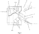
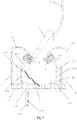
- FIGS. 1 to 5 illustrate typical unipolar architectures.
- Two static contacts are arranged in the shell of a breaking unit, which are respectively connected to the incoming connection terminals of two power supplies.
- a common arc extinguishing chamber 10 as illustrated in FIG. 4 (or two separate arc extinguishing chambers 10 as illustrated in FIG. 5 ) is arranged between the two static contacts.
- a moving contact finger is arranged below the arc extinguishing chamber and between the two static contacts, and an electromotive force compensation circuit is arranged on the two sides of the moving contact finger to provide the contact pressure for the moving contact to abut against the static contact in case of short circuit, so that it has a higher short-time withstand current performance.
- An electrical connection is arranged between the moving contact finger and the compensation circuit, and the rear end of the compensation circuit is provided with a connection terminal for connecting loads. Therefore, the working current and short-circuit current flow from the incoming side of the first power supply or the second power supply to the load through the load connection terminal after flowing through the static contact, the moving contact finger and the compensation circuit.
- a breaking unit A with electromotive force compensation is provided, wherein the breaking unit includes a first power supply static contact 1, a second power supply static contact 2, a first electromotive force compensator 5, a second electromotive force compensator 6, a moving contact component which are accommodated in the shell 9 of the breaking unit, and soft pigtail wires 7 connected between the moving contact component and the first electromotive force compensator 5 and between the moving contact component and the second electromotive force compensator 6.
- the moving contact component is pivotally arranged on the shell 9 of the breaking unit.
- the first power supply static contact 1, the second power supply static contact 2, the first electromotive force compensator 5 and the second electromotive force compensator 6 are fixedly arranged on the shell 9 of the breaking unit.
- the first power supply static contact 1 is connected to a corresponding first power supply (not illustrated).
- the second power supply static contact 2 is connected to a corresponding second power supply (not illustrated).
- the current direction in the first electromotive force compensator 5 is consistent with the current direction in the moving contact component, so as to generate mutually attractive electromotive forces, and then form a torque to drive the moving contact component to rotate, so as to increase the contact pressure between the moving contact component and the first power supply static contact 1.
- the current direction in the second electromotive force compensator 6 is consistent with the current direction in the moving contact component, so as to generate mutually attractive electromotive forces, and then form a torque driving the moving contact component to rotate, so as to increase the contact pressure between the moving contact component and the second power supply static contact 2.
- the breaking unit further includes an auxiliary shunt component (as illustrated in FIG. 7 and FIG. 8 ) accommodated in the shell of the breaking unit.
- the auxiliary shunt component includes a first shunt member 12 and a second shunt member 13.
- the first shunt member 12 is connected with the first electromotive force compensator 5.
- the second shunt member 13 is connected with the second electromotive force compensator 6.
- the moving contact component When the moving contact component is in contact with the first power supply static contact 1, the moving contact component is in contact with the first shunt member 12, and the current flowing through the first shunt member 12 is greater than the current flowing through the soft pigtail wire 7.
- the moving contact component When the moving contact component is in contact with the second power supply static contact 2, the moving contact component is in contact with the second shunt member 13, and the current flowing through the second shunt member 13 is greater than the current flowing through the soft pigtail wire 7.
- the first shunt member 12 includes a first elastic current-carrying member 12-2 and a first contact point 12-1 arranged on one end of the first elastic current-carrying member 12-2, the first elastic current-carrying member 12-2 and the first contact point 12-1 are made of conductive materials.
- the other end of the first elastic current-carrying member 12 is connected to the first electromotive force compensator.
- the second shunt member 13 includes a second elastic current-carrying member 13-2 and a second contact point 13-1 arranged on one end of the second elastic current-carrying member 13-2, the second elastic current-carrying member 13-2 and the second contact point 13-1 are made of conductive materials.
- the other end of the second elastic current-carrying member 13-2 is connected to the second electromotive force compensator.
- the first shunt member includes a first shunt contact piece 14, a first shunt spring 15 and a first shunt pigtail wire 16.
- the lower end of the first shunt contact piece 14 is pivotally connected with the shell 9 of the breaking unit, and the upper end of the first shunt contact piece 14 is provided with a first shunt contact surface 14-1 contacting with the moving contact component and a first shunting motion range limiting surface 14-2 matched with the shell 9 of the breaking unit.
- the first shunting spring 15 exerts a force on the first shunt contact piece 14 to make the first shunt contact piece 14 abut against the moving contact component and provide contact pressure between them.
- the lower end of the first shunt contact piece 14 is further connected with the first electromotive force compensator 5 through the first shunt pigtail wire 16.
- the second shunt member includes a second shunt contact piece 17, a second shunt spring 18 and a second shunt pigtail wire 19.
- the lower end of the second shunt contact piece 17 is pivotally connected with the shell 9 of the breaking unit, and the upper end of the second shunt contact piece 17 is provided with a second shunt contact surface 17-1 contacting with the moving contact component and a second shunt motion range limiting surface 17-2 matched with the shell 9 of the breaking unit.
- the second shunt spring 18 exerts a force on the second shunt contact piece 17 to make the second shunt contact piece 17 abut against the moving contact component and provide contact pressure between them.
- the lower end of the second shunt contact piece 17 is further connected with the second electromotive force compensator 6 through the second shunt pigtail wire 19.
- the force exerted by the first shunt contact piece 14 passes through the pivot center of the moving contact component, so that the contact pressure between the first shunt contact piece 14 and the moving contact component does not reduce the contact pressure between the moving contact component and the first power supply static contact 1, and does not hinder the opening of the moving contact component relative to the first power supply static contact 1.
- the force exerted by the second shunt contact piece 17 passes through the pivot center of the moving contact component, so that the contact pressure between the second shunt contact piece 17 and the moving contact component does not reduce the contact pressure between the moving contact component and the second power supply static contact 2, and does not hinder the opening of the moving contact component relative to the second power supply static contact 2.
- the moving contact component rotates between a first position and a second position.
- the moving contact component In the first position, the moving contact component is in contact with the first power supply static contact 1.
- the moving contact component In the second position, the moving contact component is in contact with the second power supply static contact 2.
- the first power supply static contact 1, the second power supply static contact 2, the first electromotive force compensator 5 and the second electromotive force compensator 6 are arranged roughly around the moving contact component.
- the first electromotive force compensator 5 includes a first current inlet end 5-1, a first current flow section 5-2, a first electromotive force compensation section 5-3 and a first load terminal section 5-4.
- the second electromotive force compensator 6 includes a second current inlet end 6-1, a second current flow section 6-2, a second electromotive force compensation section 6-3 and a second load terminal section 6-4.
- the moving contact component includes a moving contact bracket 3 and a moving contact finger 4 mounted on the moving contact bracket 3.
- the moving contact finger 4 and the moving contact bracket 3 have the same pivot center position (as illustrated in FIGS. 1 and 3 ) or different pivot center positions (as illustrated in FIG. 2 ).
- one end of the moving contact finger 4 is connected to the first current inlet end and the second current inlet end through the soft pigtail wire 7.
- the first elastic current-carrying member 12-2 is connected to the first current inlet end 5-1; the second elastic current-carrying member 13-2 is connected to the second current inlet end 6-1.
- the current direction flowing through the first electromotive force compensation section 5-3 is consistent with the current direction flowing through the moving contact finger 4, so as to generate mutually attractive electromotive forces, and then form a torque to drive the moving contact component (the moving contact finger 4) to rotate, so as to prevent the moving contact finger from repelling and further increasing the contact pressure between the moving contact component (the moving contact finger 4) and the first power supply static contact 1.
- the first elastic current-carrying member 12-2 and the second elastic current-carrying member 13-2 are made thick, while the soft pigtail wire 7 is thin, so that the current distributed to the second elastic current-carrying member 13-2 of the two member constituting the parallel circuit accounts for the vast majority.
- each contact point on the moving contact finger 4 has a normal contact pressure (for example, 30 N), so as to obtain a lower temperature rise and ensure the normal operation of the switch.
- Opening operation Driven by an operating mechanism (not illustrated), the moving contact component rotates counterclockwise from the state illustrated in FIG. 7 , and the moving contact finger 4 is disconnected from the second power supply static contact 2 and the second elastic current-carrying member 13-2 respectively. Then an arc occurs between the moving contact finger 4 and the second power supply static contact 2, and there is no arc between the moving contact finger 4 and the second elastic current-carrying member 13-2 (current flows out from the soft pigtail wire 7). Because the cross section of the soft pigtail wire 7 is small, it is soft and will not hinder the movement of the moving contact finger 4, so that it can open quickly and lengthen the arc, thus extinguishing the arc quickly and obtaining higher electrical operation performance. The closing operation process is opposite to the opening operation, so it will not be repeated here.
- Short-time withstand current Icw: Most of the current flows into from the second power supply static contact 2 ⁇ the moving contact finger 4 ⁇ the second elastic current-carrying member 13-2 ⁇ and finally flows out from the second electromotive force compensator 6.
- An electromotive force to make the moving contact finger 4 rotate clockwise is generated between the second electromotive force compensation section 6-3 and the moving contact finger 4, so as to increase the contact pressure between the moving contact finger 4 and the second power supply static contact 2, and keep them closed (not repelled).
- the second elastic current-carrying member 13-2 is repelled by the action of the electromotive force, so that all current flows into through the second power supply static contact 2 ⁇ the moving contact finger 4 ⁇ the soft pigtail wire 7 ⁇ and finally flows out from the second electromotive force compensator 6.
- the second elastic current-carrying member 13 is closed with the moving contact finger 4 again, and the current flows as before. In this way, the second elastic current-carrying member 13-2 and the soft pigtail wire 7 alternately carry large current, which meets the performance requirements of the product.
- Short-circuit making current (Icm): The moving contact finger 4 is driven by the operating mechanism from the vertical middle position to the closing position illustrated in Figure 7 . Then, most of the current flows in from the second power supply static contact 2 ⁇ the moving contact finger 4 ⁇ the second elastic current-carrying member 13-2 ⁇ and finally flows out from the second electromotive force compensator 6. An electromotive force to make the moving contact finger 4 rotate clockwise is generated between the second electromotive force compensation section 6-3 and the moving contact finger 4, so as to increase the contact pressure between the moving contact finger 4 and the second power supply static contact 2, and keep them closed (not repelled).
- the second elastic current-carrying member 13-2 is repelled by the action of the electromotive force, so that all the current flows in through the second power supply static contact 2 ⁇ the moving contact finger 4 ⁇ the soft pigtail wire 7 ⁇ and finally flows out from the second electromotive force compensator 6. Then, because the current flowing through the second elastic current-carrying member 13-2 disappears, the second elastic current-carrying member 13-2 is closed with the moving contact finger 4 again, and the current flows as before. In this way, the second elastic current-carrying member 13-2 and the soft pigtail wire 7 alternately carry large current, which meets the performance requirements of the product.
- the second elastic current-carrying member 13-2 will receive the Laplace force from the second electromotive force compensator 6 and the holm force from the moving contact finger 4.
- the repulsion of the second elastic current-carrying member 13-2 is allowed, but it is desired to close immediately after being repelled, and repelled and closed again, so as to carry the heat of short-circuit current as much as possible. Therefore, the analysis of Laplace force is necessary, because it always exists in the time period when current flows. Experimental analysis proves that it is small enough to not affect repulsion, thus ensuring the performance.
- the experimental analysis also proves that when the second electromotive force compensation section 6-3 and the moving contact finger 4 are close to each other and the second electromotive force compensation section 6-3 (hypotenuse section) is short, the Laplace electromotive force repelling the second elastic current-carrying member 13-2 can be reduced.
- the proportion of electromotive force provided by the first electromotive force compensation section and the second electromotive force compensation section to the moving contact finger is the largest, so it can be arranged on a plane different from the moving contact component, so that it coincides with the moving contact finger in Figure 2 to obtain larger electromotive force (in this case, no magnetizer is needed).
- the first electromotive force compensation section 5-3 and the second electromotive force compensation section 6-3 are respectively provided with at least one magnetizer 8.
- a dual-power transfer switch is provided, wherein the dual-power transfer switch includes at least one breaking unit as described above.
- a first unipolar breaking unit in a first state is formed by installing two power supply incoming static contacts, a connecting terminal and a compensation circuit. After the first pole of the moving contact component is put into the first unipolar breaking unit in the first state, connecting it to the compensation circuit with the pigtail wire at the tail of the moving contact finger. After the second pole of the moving contact component is put into a second unipolar breaking unit in the first state, connecting it to the compensation circuit with the pigtail wire at the tail of the moving contact finger. After the third pole of the moving contact component is put into a third unipolar breaking unit in the first state, connecting it to the compensation circuit with the pigtail wire at the tail of the moving contact finger.
- the four-pole breaking unit is connected with the ATS mechanism (not illustrated) through a coupling 11 to form a complete dual-power transfer switch (TSE, i.e., transfer switching equipment).
- TSE dual-power transfer switch
- TSE When TSE receives a short-circuit current from double-off position, because of the existence of compensation circuit, the greater the short-circuit current, the greater the electric compensation force, thus always pressing the finger of the moving contact against the static contact, so as to obtain higher short-circuit making current, i.e., Icm.
Landscapes
- Physics & Mathematics (AREA)
- Electromagnetism (AREA)
- Breakers (AREA)
- Current-Collector Devices For Electrically Propelled Vehicles (AREA)
- Contacts (AREA)
Claims (14)
- Unterbrechungseinheit mit einer Hilfsnebenschlusskomponente,wobei die Unterbrechungseinheit einen ersten statischen Stromversorgungskontakt (1), einen zweiten statischen Stromversorgungskontakt (2), eine erste Kompensationsvorrichtung für eine elektromotorische Kraft (5), eine zweite Kompensationsvorrichtung für eine elektromotorische Kraft (6), eine bewegliche Kontaktkomponente, die in einem Gehäuse (9) der Unterbrechungseinheit untergebracht sind, und weiche bewegliche Anschlussdrähte (7) umfasst;dadurch gekennzeichnet, dass die beweglichen Anschlussdrähte zwischen der beweglichen Kontaktkomponente und der ersten Kompensationsvorrichtung für eine elektromotorische Kraft und zwischen der beweglichen Kontaktkomponente und der zweiten Kompensationsvorrichtung für eine elektromotorische Kraft angeschlossen sind;wobei die Hilfsnebenschlusskomponente ein erstes Nebenschlusselement (12) und ein zweites Nebenschlusselement (13) umfasst;wobei das erste Nebenschlusselement mit der ersten Kompensationsvorrichtung für eine elektromotorische Kraft verbunden ist;wobei das zweite Nebenschlusselement mit der zweiten Kompensationsvorrichtung für eine elektromotorische Kraft verbunden ist;wenn die bewegliche Kontaktkomponente in Kontakt mit dem ersten statischen Stromversorgungskontakt steht, die bewegliche Kontaktkomponente in Kontakt mit dem ersten Nebenschlusselement steht und ein Strom, der durch das erste Nebenschlusselement fließt, größer ist als ein Strom, der durch den weichen beweglichen Anschlussdraht fließt;wenn die bewegliche Kontaktkomponente in Kontakt mit dem zweiten statischen Stromversorgungskontakt steht, die bewegliche Kontaktkomponente in Kontakt mit dem zweiten Nebenschlusselement steht und ein Strom, der durch das zweite Nebenschlusselement fließt, größer ist als ein Strom, der durch den weichen beweglichen Anschlussdraht fließt.
- Unterbrechungseinheit nach Anspruch 1,wobei das erste Nebenschlusselement (12) ein erstes elastisches stromführendes Element (12-2) und einen ersten Kontaktpunkt (12-1) umfasst, der an einem Ende des ersten elastischen stromführenden Elements angeordnet ist, wobei das erste elastische stromführende Element und der erste Kontaktpunkt aus leitenden Materialien hergestellt sind;wobei ein anderes Ende des ersten elastischen stromführenden Elements mit der ersten Kompensationsvorrichtung für eine elektromotorische Kraft (5) verbunden ist;wobei das zweite Nebenschlusselement (13) ein zweites elastisches stromführendes Element (13-2) und einen zweiten Kontaktpunkt (13-1) umfasst, der an einem Ende des zweiten elastischen stromführenden Elements angeordnet ist, wobei das zweite elastische stromführende Element und der zweite Kontaktpunkt aus leitenden Materialien hergestellt sind;wobei ein anderes Ende des zweiten elastischen stromführenden Elements mit der zweiten Kompensationsvorrichtung für eine elektromotorische Kraft (6) verbunden ist.
- Unterbrechungseinheit nach Anspruch 1,wobei das erste Nebenschlusselement ein erstes Nebenschlusskontaktstück (14), eine erste Nebenschlussfeder (15) und einen ersten beweglichen Nebenschluss-Anschlussdraht (16) umfasst;wobei ein unteres Ende des ersten Nebenschlusskontaktstücks schwenkbar mit dem Gehäuse (9) der Unterbrechungseinheit verbunden ist, ein oberes Ende des ersten Nebenschlusskontaktstücks mit einer ersten Nebenschlusskontaktfläche (14-1), die mit der beweglichen Kontaktkomponente in Kontakt steht, und einer ersten Nebenschlussbewegungsbereich-Begrenzungsfläche (14-2) versehen ist, die an das Gehäuse der Unterbrechungseinheit angepasst ist; die erste Nebenschlussfeder so konfiguriert ist, dass sie eine Kraft auf das erste Nebenschlusskontaktstück ausübt, um das erste Nebenschlusskontaktstück gegen die bewegliche Kontaktkomponente stoßen zu lassen und einen Kontaktdruck zwischen ihnen bereitzustellen; und das untere Ende des ersten Nebenschlusskontaktstücks ferner mit der ersten Kompensationsvorrichtung für eine elektromotorische Kraft durch den ersten beweglichen Nebenschluss-Anschlussdraht verbunden ist;wobei das zweite Nebenschlusselement ein zweites Nebenschlusskontaktstück (17), eine zweite Nebenschlussfeder (18) und einen zweiten beweglichen Nebenschluss-Anschlussdraht (19) umfasst;wobei ein unteres Ende des zweiten Nebenschlusskontaktstücks schwenkbar mit dem Gehäuse der Unterbrechungseinheit verbunden ist, ein oberes Ende des zweiten Nebenschlusskontaktstücks mit einer zweiten Nebenschlusskontaktfläche (17-1), die mit der beweglichen Kontaktkomponente in Kontakt steht, und einer zweiten Nebenschlussbewegungsbereich-Begrenzungsfläche (17-2) versehen ist, die an das Gehäuse der Unterbrechungseinheit angepasst ist; die zweite Nebenschlussfeder so konfiguriert ist, dass sie eine Kraft auf das zweite Nebenschlusskontaktstück ausübt, um das zweite Nebenschlusskontaktstück gegen die bewegliche Kontaktkomponente stoßen zu lassen und einen Kontaktdruck zwischen ihnen bereitzustellen; und das untere Ende des zweiten Nebenschlusskontaktstücks ferner mit der zweiten Kompensationsvorrichtung für eine elektromotorische Kraft durch den zweiten beweglichen Nebenschluss-Anschlussdraht verbunden ist.
- Unterbrechungseinheit nach Anspruch 3,wobei die von dem ersten Nebenschlusskontaktstück (14) ausgeübte Kraft durch einen Drehpunkt der beweglichen Kontaktkomponente verläuft, so dass der Kontaktdruck zwischen dem ersten Nebenschlusskontaktstück und der beweglichen Kontaktkomponente den Kontaktdruck zwischen der beweglichen Kontaktkomponente und dem ersten statischen Stromversorgungskontakt nicht verringert und das Öffnen der beweglichen Kontaktkomponente relativ zu dem ersten statischen Stromversorgungskontakt nicht behindert;wobei die von dem zweiten Nebenschlusskontaktstück (17) ausgeübte Kraft durch den Drehpunkt der beweglichen Kontaktkomponente verläuft, so dass der Kontaktdruck zwischen dem zweiten Nebenschlusskontaktstück und der beweglichen Kontaktkomponente den Kontaktdruck zwischen der beweglichen Kontaktkomponente und dem zweiten statischen Stromversorgungskontakt nicht verringert und das Öffnen der beweglichen Kontaktkomponente relativ zu dem zweiten statischen Stromversorgungskontakt nicht behindert.
- Unterbrechungseinheit nach Anspruch 2,wobei, wenn die bewegliche Kontaktkomponente in Kontakt mit dem ersten statischen Stromversorgungskontakt (1) steht, eine Stromrichtung in der ersten Kompensationsvorrichtung für eine elektromotorische Kraft mit einer Stromrichtung in der beweglichen Kontaktkomponente übereinstimmt, um gegenseitig anziehende elektromotorische Kräfte zu erzeugen und dann ein Drehmoment zu bilden, das die bewegliche Kontaktkomponente zum Drehen antreibt, um einen Kontaktdruck zwischen der beweglichen Kontaktkomponente und dem ersten statischen Stromversorgungskontakt zu erhöhen;wobei, wenn die bewegliche Kontaktkomponente in Kontakt mit dem zweiten statischen Stromversorgungskontakt (2) steht, eine Stromrichtung in der zweiten Kompensationsvorrichtung für eine elektromotorische Kraft mit einer Stromrichtung in der beweglichen Kontaktkomponente übereinstimmt, um gegenseitig anziehende elektromotorische Kräfte zu erzeugen und dann ein Drehmoment zu bilden, das die bewegliche Kontaktkomponente zum Drehen antreibt, um einen Kontaktdruck zwischen der beweglichen Kontaktkomponente und dem zweiten statischen Stromversorgungskontakt zu erhöhen;wobei bei einem Anstieg des Stroms die elektromotorische Kraft zunimmt.
- Unterbrechungseinheit nach Anspruch 5,wobei die bewegliche Kontaktkomponente konfiguriert ist, um sich zwischen einer ersten Position und einer zweiten Position zu drehen;wobei in der ersten Position die bewegliche Kontaktkomponente in Kontakt mit dem ersten statischen Stromversorgungskontakt steht;wobei in der zweiten Position die bewegliche Kontaktkomponente in Kontakt mit dem zweiten statischen Stromversorgungskontakt steht.
- Unterbrechungseinheit nach Anspruch 6,
wobei der erste statische Stromversorgungskontakt, der zweite statische Stromversorgungskontakt, die erste Kompensationsvorrichtung für eine elektromotorische Kraft und die zweite Kompensationsvorrichtung für eine elektromotorische Kraft um die bewegliche Kontaktkomponente herum angeordnet sind. - Unterbrechungseinheit nach Anspruch 6,
wobei die erste Kompensationsvorrichtung für eine elektromotorische Kraft ein erstes Stromeinlassende (5-1), einen ersten Stromflussabschnitt (5-2), einen ersten Abschnitt (5-3) zur Kompensation einer elektromotorischen Kraft und einen ersten Lastanschlussabschnitt (5-4) umfasst. - Unterbrechungseinheit nach Anspruch 8,
wobei die zweite Kompensationsvorrichtung für eine elektromotorische Kraft ein zweites Stromeinlassende (6-1), einen zweiten Stromflussabschnitt (6-2), einen zweiten Abschnitt (6-3) zur Kompensation einer elektromotorischen Kraft und einen zweiten Lastanschlussabschnitt (6-4) umfasst. - Unterbrechungseinheit nach Anspruch 9,wobei die bewegliche Kontaktkomponente eine bewegliche Kontakthalterung (3) und einen beweglichen Kontaktfinger (4) umfasst, der an der beweglichen Kontakthalterung angebracht ist;wobei der bewegliche Kontaktfinger und die bewegliche Kontakthalterung die gleiche Drehpunktposition oder unterschiedliche Drehpunktpositionen aufweisen.
- Unterbrechungseinheit nach Anspruch 10,wobei ein Ende des beweglichen Kontaktfingers mit dem ersten Stromeinlassende und dem zweiten Stromeinlassende über die weichen beweglichen Anschlussdrähte (7) verbunden ist;wobei das erste elastische stromführende Element mit dem ersten Stromeinlassende verbunden ist;wobei das zweite elastische stromführende Element mit dem zweiten Stromeinlassende verbunden ist.
- Unterbrechungseinheit nach Anspruch 11,wobei, wenn sich die bewegliche Kontaktkomponente in der ersten Position befindet, Strom durch den beweglichen Kontaktfinger, den weichen beweglichen Anschlussdraht und das erste elastische stromführende Element, die parallel miteinander verbunden sind, das erste Stromeinlassende, den ersten Stromflussabschnitt, den ersten Abschnitt zur Kompensation einer elektromotorischen Kraft und den ersten Lastanschlussabschnitt fließt, und eine Richtung des Stroms, der durch den ersten Abschnitt zur Kompensation einer elektromotorischen Kraft fließt, mit einer Richtung des Stroms, der durch den beweglichen Kontaktfinger fließt, übereinstimmt;wobei, wenn sich die bewegliche Kontaktkomponente in der zweiten Position befindet, Strom durch den beweglichen Kontaktfinger, den weichen beweglichen Anschlussdraht und das zweite elastische stromführende Element, die parallel miteinander verbunden sind, das zweite Stromeinlassende, den zweiten Stromflussabschnitt, den zweiten Abschnitt zur Kompensation einer elektromotorischen Kraft und den zweiten Lastanschlussabschnitt fließt, und eine Richtung des Stroms, der durch den zweiten Abschnitt zur Kompensation einer elektromotorischen Kraft fließt, mit der Richtung des Stroms, der durch den beweglichen Kontaktfinger fließt, übereinstimmt.
- Unterbrechungseinheit nach Anspruch 10,
wobei der erste Abschnitt zur Kompensation einer elektromotorischen Kraft und der zweite Abschnitt zur Kompensation einer elektromotorischen Kraft jeweils mit mindestens einer Magnetisierungsvorrichtung (8) versehen sind. - Doppelleistungsumschalter, wobei der Doppelleistungsumschalter mindestens eine Unterbrechungseinheit nach einem der Ansprüche 1 bis 13 umfasst.
Applications Claiming Priority (1)
| Application Number | Priority Date | Filing Date | Title |
|---|---|---|---|
| CN202010589038.2A CN113838687B (zh) | 2020-06-24 | 2020-06-24 | 具有辅助分流组件的分断单元和双电源转换开关 |
Publications (2)
| Publication Number | Publication Date |
|---|---|
| EP3929952A1 EP3929952A1 (de) | 2021-12-29 |
| EP3929952B1 true EP3929952B1 (de) | 2022-12-21 |
Family
ID=76807584
Family Applications (1)
| Application Number | Title | Priority Date | Filing Date |
|---|---|---|---|
| EP21305848.0A Active EP3929952B1 (de) | 2020-06-24 | 2021-06-21 | Unterbrechereinheit mit hilfsnebenschlusskomponente und doppelstromübertragungsschalter |
Country Status (4)
| Country | Link |
|---|---|
| EP (1) | EP3929952B1 (de) |
| CN (1) | CN113838687B (de) |
| AU (1) | AU2021204113B2 (de) |
| RU (1) | RU2765687C1 (de) |
Family Cites Families (15)
| Publication number | Priority date | Publication date | Assignee | Title |
|---|---|---|---|---|
| US4849590A (en) * | 1988-04-01 | 1989-07-18 | Kohler Company | Electric switch with counteracting electro-electro-dynamic forces |
| FR2703821B1 (fr) * | 1993-04-07 | 1995-05-12 | Merlin Gerin | Disjoncteur électrique à répulsion électrodynamique des contacts et à chambres de coupure double. |
| US5682772A (en) * | 1995-04-20 | 1997-11-04 | U.S. Controls Corporation | Lid switch with contact failure detection |
| US5874699A (en) * | 1997-09-18 | 1999-02-23 | Eaton Corporation | Molded case circuit breaker and moving conductor assembly therefor |
| US6815624B2 (en) * | 2002-03-28 | 2004-11-09 | General Electric Company | Methods and apparatus for transferring electrical power |
| KR101150334B1 (ko) * | 2011-02-08 | 2012-06-08 | 엘에스산전 주식회사 | 진공차단기의 플렉서블 션트 |
| CN203367173U (zh) * | 2013-07-25 | 2013-12-25 | 浙江格蕾特电器有限公司 | 三合一硬连接磁保持继电器 |
| DE102015108129B4 (de) * | 2014-05-30 | 2020-06-18 | Eaton Intelligent Power Limited | Schutzschalter mit einfach herzustellender Schaltwelle, Negativform zur Herstellung einer Schaltwelle eines derartigen Schutzschalters und Verfahren zur Herstellung einer Schaltwelle eines derartigen Schutzschalters |
| ES2687030T3 (es) * | 2015-01-15 | 2018-10-23 | Schneider Electric Industries Sas | Sistema de ruptura de derivación |
| US10083809B2 (en) * | 2016-04-21 | 2018-09-25 | Hartland Controls, Llc | Electrical power transfer switch |
| US9865416B2 (en) * | 2016-04-21 | 2018-01-09 | Hartland Controls, Llc | Electrical power transfer switch |
| CN107026059A (zh) * | 2017-06-10 | 2017-08-08 | 南京日新科技有限公司 | 一种多断点断路器 |
| CN207338255U (zh) * | 2017-09-19 | 2018-05-08 | 上海电器科学研究所(集团)有限公司 | 具有电动力补偿功能的导电回路 |
| CN111029183B (zh) * | 2019-12-31 | 2024-11-01 | 常熟开关制造有限公司(原常熟开关厂) | 双电源转换开关 |
| CN212783116U (zh) * | 2020-06-24 | 2021-03-23 | 施耐德电器工业公司 | 具有辅助分流组件的分断单元和双电源转换开关 |
-
2020
- 2020-06-24 CN CN202010589038.2A patent/CN113838687B/zh active Active
-
2021
- 2021-06-18 AU AU2021204113A patent/AU2021204113B2/en active Active
- 2021-06-21 EP EP21305848.0A patent/EP3929952B1/de active Active
- 2021-06-23 RU RU2021118283A patent/RU2765687C1/ru active
Also Published As
| Publication number | Publication date |
|---|---|
| AU2021204113A1 (en) | 2022-01-20 |
| CN113838687A (zh) | 2021-12-24 |
| CN113838687B (zh) | 2025-08-26 |
| AU2021204113B2 (en) | 2022-03-17 |
| RU2765687C1 (ru) | 2022-02-02 |
| EP3929952A1 (de) | 2021-12-29 |
Similar Documents
| Publication | Publication Date | Title |
|---|---|---|
| CN103177884B (zh) | 低压电器的触头结构 | |
| CN101656179B (zh) | 同向式串联双断点小型断路器 | |
| CN107359068A (zh) | 一种具有复合灭弧性能的塑壳断路器 | |
| SE424242B (sv) | Elektromagnetisk manovrerad elkopplare | |
| CN101170034A (zh) | 小型断路器 | |
| CA2364989A1 (en) | Circuit breaker with bypass conductor commutating current out of the bimetal during short circuit interruption and method of commutating current out of bimetal | |
| CN212783116U (zh) | 具有辅助分流组件的分断单元和双电源转换开关 | |
| EP3929952B1 (de) | Unterbrechereinheit mit hilfsnebenschlusskomponente und doppelstromübertragungsschalter | |
| US1720566A (en) | Circuit-controlling device | |
| CN101170031B (zh) | 快速分断低压电路断路器 | |
| CN222233548U (zh) | 一种断路器 | |
| CN207367828U (zh) | 一种高分断小型断路器 | |
| CN212392149U (zh) | 具有电动力补偿的分断单元和自动双电源转换开关 | |
| CN212161728U (zh) | 一种智能断路器 | |
| KR101579698B1 (ko) | 회로차단기 | |
| CN111627777B (zh) | 一种断路器 | |
| CN120183974A (zh) | 一种断路器 | |
| US4507527A (en) | Current limiting circuit-breaker having an improved contact arrangement | |
| CN212934535U (zh) | 一种低压断路器的接触系统 | |
| CN214624939U (zh) | 一种换流断路器 | |
| CN201054339Y (zh) | 快速分断低压电路断路器 | |
| CN204464214U (zh) | 一种直流断路器变转轴触头结构 | |
| US3158720A (en) | Contact assembly having hinge means utilizing electrodynamic forces of current flow therethrough | |
| CN2228686Y (zh) | 小型断路器 | |
| CN209544267U (zh) | 一种断路器 |
Legal Events
| Date | Code | Title | Description |
|---|---|---|---|
| PUAI | Public reference made under article 153(3) epc to a published international application that has entered the european phase |
Free format text: ORIGINAL CODE: 0009012 |
|
| STAA | Information on the status of an ep patent application or granted ep patent |
Free format text: STATUS: THE APPLICATION HAS BEEN PUBLISHED |
|
| AK | Designated contracting states |
Kind code of ref document: A1 Designated state(s): AL AT BE BG CH CY CZ DE DK EE ES FI FR GB GR HR HU IE IS IT LI LT LU LV MC MK MT NL NO PL PT RO RS SE SI SK SM TR |
|
| B565 | Issuance of search results under rule 164(2) epc |
Effective date: 20211124 |
|
| STAA | Information on the status of an ep patent application or granted ep patent |
Free format text: STATUS: REQUEST FOR EXAMINATION WAS MADE |
|
| 17P | Request for examination filed |
Effective date: 20220221 |
|
| RBV | Designated contracting states (corrected) |
Designated state(s): AL AT BE BG CH CY CZ DE DK EE ES FI FR GB GR HR HU IE IS IT LI LT LU LV MC MK MT NL NO PL PT RO RS SE SI SK SM TR |
|
| GRAP | Despatch of communication of intention to grant a patent |
Free format text: ORIGINAL CODE: EPIDOSNIGR1 |
|
| STAA | Information on the status of an ep patent application or granted ep patent |
Free format text: STATUS: GRANT OF PATENT IS INTENDED |
|
| RIC1 | Information provided on ipc code assigned before grant |
Ipc: H01H 50/54 20060101ALI20220622BHEP Ipc: H01H 19/46 20060101ALI20220622BHEP Ipc: H01H 1/22 20060101AFI20220622BHEP |
|
| INTG | Intention to grant announced |
Effective date: 20220711 |
|
| GRAS | Grant fee paid |
Free format text: ORIGINAL CODE: EPIDOSNIGR3 |
|
| GRAA | (expected) grant |
Free format text: ORIGINAL CODE: 0009210 |
|
| STAA | Information on the status of an ep patent application or granted ep patent |
Free format text: STATUS: THE PATENT HAS BEEN GRANTED |
|
| AK | Designated contracting states |
Kind code of ref document: B1 Designated state(s): AL AT BE BG CH CY CZ DE DK EE ES FI FR GB GR HR HU IE IS IT LI LT LU LV MC MK MT NL NO PL PT RO RS SE SI SK SM TR |
|
| REG | Reference to a national code |
Ref country code: GB Ref legal event code: FG4D |
|
| REG | Reference to a national code |
Ref country code: CH Ref legal event code: EP |
|
| REG | Reference to a national code |
Ref country code: DE Ref legal event code: R096 Ref document number: 602021001041 Country of ref document: DE |
|
| REG | Reference to a national code |
Ref country code: AT Ref legal event code: REF Ref document number: 1539547 Country of ref document: AT Kind code of ref document: T Effective date: 20230115 |
|
| REG | Reference to a national code |
Ref country code: IE Ref legal event code: FG4D |
|
| REG | Reference to a national code |
Ref country code: LT Ref legal event code: MG9D |
|
| REG | Reference to a national code |
Ref country code: NL Ref legal event code: MP Effective date: 20221221 |
|
| PG25 | Lapsed in a contracting state [announced via postgrant information from national office to epo] |
Ref country code: SE Free format text: LAPSE BECAUSE OF FAILURE TO SUBMIT A TRANSLATION OF THE DESCRIPTION OR TO PAY THE FEE WITHIN THE PRESCRIBED TIME-LIMIT Effective date: 20221221 Ref country code: NO Free format text: LAPSE BECAUSE OF FAILURE TO SUBMIT A TRANSLATION OF THE DESCRIPTION OR TO PAY THE FEE WITHIN THE PRESCRIBED TIME-LIMIT Effective date: 20230321 Ref country code: LT Free format text: LAPSE BECAUSE OF FAILURE TO SUBMIT A TRANSLATION OF THE DESCRIPTION OR TO PAY THE FEE WITHIN THE PRESCRIBED TIME-LIMIT Effective date: 20221221 Ref country code: FI Free format text: LAPSE BECAUSE OF FAILURE TO SUBMIT A TRANSLATION OF THE DESCRIPTION OR TO PAY THE FEE WITHIN THE PRESCRIBED TIME-LIMIT Effective date: 20221221 |
|
| REG | Reference to a national code |
Ref country code: AT Ref legal event code: MK05 Ref document number: 1539547 Country of ref document: AT Kind code of ref document: T Effective date: 20221221 |
|
| PG25 | Lapsed in a contracting state [announced via postgrant information from national office to epo] |
Ref country code: RS Free format text: LAPSE BECAUSE OF FAILURE TO SUBMIT A TRANSLATION OF THE DESCRIPTION OR TO PAY THE FEE WITHIN THE PRESCRIBED TIME-LIMIT Effective date: 20221221 Ref country code: LV Free format text: LAPSE BECAUSE OF FAILURE TO SUBMIT A TRANSLATION OF THE DESCRIPTION OR TO PAY THE FEE WITHIN THE PRESCRIBED TIME-LIMIT Effective date: 20221221 Ref country code: HR Free format text: LAPSE BECAUSE OF FAILURE TO SUBMIT A TRANSLATION OF THE DESCRIPTION OR TO PAY THE FEE WITHIN THE PRESCRIBED TIME-LIMIT Effective date: 20221221 Ref country code: GR Free format text: LAPSE BECAUSE OF FAILURE TO SUBMIT A TRANSLATION OF THE DESCRIPTION OR TO PAY THE FEE WITHIN THE PRESCRIBED TIME-LIMIT Effective date: 20230322 |
|
| PG25 | Lapsed in a contracting state [announced via postgrant information from national office to epo] |
Ref country code: NL Free format text: LAPSE BECAUSE OF FAILURE TO SUBMIT A TRANSLATION OF THE DESCRIPTION OR TO PAY THE FEE WITHIN THE PRESCRIBED TIME-LIMIT Effective date: 20221221 |
|
| PG25 | Lapsed in a contracting state [announced via postgrant information from national office to epo] |
Ref country code: SM Free format text: LAPSE BECAUSE OF FAILURE TO SUBMIT A TRANSLATION OF THE DESCRIPTION OR TO PAY THE FEE WITHIN THE PRESCRIBED TIME-LIMIT Effective date: 20221221 Ref country code: RO Free format text: LAPSE BECAUSE OF FAILURE TO SUBMIT A TRANSLATION OF THE DESCRIPTION OR TO PAY THE FEE WITHIN THE PRESCRIBED TIME-LIMIT Effective date: 20221221 Ref country code: PT Free format text: LAPSE BECAUSE OF FAILURE TO SUBMIT A TRANSLATION OF THE DESCRIPTION OR TO PAY THE FEE WITHIN THE PRESCRIBED TIME-LIMIT Effective date: 20230421 Ref country code: ES Free format text: LAPSE BECAUSE OF FAILURE TO SUBMIT A TRANSLATION OF THE DESCRIPTION OR TO PAY THE FEE WITHIN THE PRESCRIBED TIME-LIMIT Effective date: 20221221 Ref country code: EE Free format text: LAPSE BECAUSE OF FAILURE TO SUBMIT A TRANSLATION OF THE DESCRIPTION OR TO PAY THE FEE WITHIN THE PRESCRIBED TIME-LIMIT Effective date: 20221221 Ref country code: CZ Free format text: LAPSE BECAUSE OF FAILURE TO SUBMIT A TRANSLATION OF THE DESCRIPTION OR TO PAY THE FEE WITHIN THE PRESCRIBED TIME-LIMIT Effective date: 20221221 Ref country code: AT Free format text: LAPSE BECAUSE OF FAILURE TO SUBMIT A TRANSLATION OF THE DESCRIPTION OR TO PAY THE FEE WITHIN THE PRESCRIBED TIME-LIMIT Effective date: 20221221 |
|
| PG25 | Lapsed in a contracting state [announced via postgrant information from national office to epo] |
Ref country code: SK Free format text: LAPSE BECAUSE OF FAILURE TO SUBMIT A TRANSLATION OF THE DESCRIPTION OR TO PAY THE FEE WITHIN THE PRESCRIBED TIME-LIMIT Effective date: 20221221 Ref country code: PL Free format text: LAPSE BECAUSE OF FAILURE TO SUBMIT A TRANSLATION OF THE DESCRIPTION OR TO PAY THE FEE WITHIN THE PRESCRIBED TIME-LIMIT Effective date: 20221221 Ref country code: IS Free format text: LAPSE BECAUSE OF FAILURE TO SUBMIT A TRANSLATION OF THE DESCRIPTION OR TO PAY THE FEE WITHIN THE PRESCRIBED TIME-LIMIT Effective date: 20230421 Ref country code: AL Free format text: LAPSE BECAUSE OF FAILURE TO SUBMIT A TRANSLATION OF THE DESCRIPTION OR TO PAY THE FEE WITHIN THE PRESCRIBED TIME-LIMIT Effective date: 20221221 |
|
| REG | Reference to a national code |
Ref country code: DE Ref legal event code: R097 Ref document number: 602021001041 Country of ref document: DE |
|
| PLBE | No opposition filed within time limit |
Free format text: ORIGINAL CODE: 0009261 |
|
| STAA | Information on the status of an ep patent application or granted ep patent |
Free format text: STATUS: NO OPPOSITION FILED WITHIN TIME LIMIT |
|
| PG25 | Lapsed in a contracting state [announced via postgrant information from national office to epo] |
Ref country code: DK Free format text: LAPSE BECAUSE OF FAILURE TO SUBMIT A TRANSLATION OF THE DESCRIPTION OR TO PAY THE FEE WITHIN THE PRESCRIBED TIME-LIMIT Effective date: 20221221 |
|
| 26N | No opposition filed |
Effective date: 20230922 |
|
| PG25 | Lapsed in a contracting state [announced via postgrant information from national office to epo] |
Ref country code: MC Free format text: LAPSE BECAUSE OF FAILURE TO SUBMIT A TRANSLATION OF THE DESCRIPTION OR TO PAY THE FEE WITHIN THE PRESCRIBED TIME-LIMIT Effective date: 20221221 |
|
| PG25 | Lapsed in a contracting state [announced via postgrant information from national office to epo] |
Ref country code: SI Free format text: LAPSE BECAUSE OF FAILURE TO SUBMIT A TRANSLATION OF THE DESCRIPTION OR TO PAY THE FEE WITHIN THE PRESCRIBED TIME-LIMIT Effective date: 20221221 Ref country code: MC Free format text: LAPSE BECAUSE OF FAILURE TO SUBMIT A TRANSLATION OF THE DESCRIPTION OR TO PAY THE FEE WITHIN THE PRESCRIBED TIME-LIMIT Effective date: 20221221 |
|
| REG | Reference to a national code |
Ref country code: BE Ref legal event code: MM Effective date: 20230630 |
|
| PG25 | Lapsed in a contracting state [announced via postgrant information from national office to epo] |
Ref country code: LU Free format text: LAPSE BECAUSE OF NON-PAYMENT OF DUE FEES Effective date: 20230621 |
|
| REG | Reference to a national code |
Ref country code: IE Ref legal event code: MM4A |
|
| PG25 | Lapsed in a contracting state [announced via postgrant information from national office to epo] |
Ref country code: LU Free format text: LAPSE BECAUSE OF NON-PAYMENT OF DUE FEES Effective date: 20230621 |
|
| PG25 | Lapsed in a contracting state [announced via postgrant information from national office to epo] |
Ref country code: IE Free format text: LAPSE BECAUSE OF NON-PAYMENT OF DUE FEES Effective date: 20230621 |
|
| PG25 | Lapsed in a contracting state [announced via postgrant information from national office to epo] |
Ref country code: IE Free format text: LAPSE BECAUSE OF NON-PAYMENT OF DUE FEES Effective date: 20230621 |
|
| PG25 | Lapsed in a contracting state [announced via postgrant information from national office to epo] |
Ref country code: IT Free format text: LAPSE BECAUSE OF FAILURE TO SUBMIT A TRANSLATION OF THE DESCRIPTION OR TO PAY THE FEE WITHIN THE PRESCRIBED TIME-LIMIT Effective date: 20221221 Ref country code: BE Free format text: LAPSE BECAUSE OF NON-PAYMENT OF DUE FEES Effective date: 20230630 |
|
| PG25 | Lapsed in a contracting state [announced via postgrant information from national office to epo] |
Ref country code: BG Free format text: LAPSE BECAUSE OF FAILURE TO SUBMIT A TRANSLATION OF THE DESCRIPTION OR TO PAY THE FEE WITHIN THE PRESCRIBED TIME-LIMIT Effective date: 20221221 |
|
| PG25 | Lapsed in a contracting state [announced via postgrant information from national office to epo] |
Ref country code: BG Free format text: LAPSE BECAUSE OF FAILURE TO SUBMIT A TRANSLATION OF THE DESCRIPTION OR TO PAY THE FEE WITHIN THE PRESCRIBED TIME-LIMIT Effective date: 20221221 |
|
| REG | Reference to a national code |
Ref country code: CH Ref legal event code: PL |
|
| PG25 | Lapsed in a contracting state [announced via postgrant information from national office to epo] |
Ref country code: CH Free format text: LAPSE BECAUSE OF NON-PAYMENT OF DUE FEES Effective date: 20240630 |
|
| PGFP | Annual fee paid to national office [announced via postgrant information from national office to epo] |
Ref country code: DE Payment date: 20250626 Year of fee payment: 5 |
|
| PGFP | Annual fee paid to national office [announced via postgrant information from national office to epo] |
Ref country code: FR Payment date: 20250624 Year of fee payment: 5 |
|
| PG25 | Lapsed in a contracting state [announced via postgrant information from national office to epo] |
Ref country code: CY Free format text: LAPSE BECAUSE OF FAILURE TO SUBMIT A TRANSLATION OF THE DESCRIPTION OR TO PAY THE FEE WITHIN THE PRESCRIBED TIME-LIMIT; INVALID AB INITIO Effective date: 20210621 |
|
| PG25 | Lapsed in a contracting state [announced via postgrant information from national office to epo] |
Ref country code: HU Free format text: LAPSE BECAUSE OF FAILURE TO SUBMIT A TRANSLATION OF THE DESCRIPTION OR TO PAY THE FEE WITHIN THE PRESCRIBED TIME-LIMIT; INVALID AB INITIO Effective date: 20210621 |
|
| PG25 | Lapsed in a contracting state [announced via postgrant information from national office to epo] |
Ref country code: TR Free format text: LAPSE BECAUSE OF FAILURE TO SUBMIT A TRANSLATION OF THE DESCRIPTION OR TO PAY THE FEE WITHIN THE PRESCRIBED TIME-LIMIT Effective date: 20221221 |
|
| GBPC | Gb: european patent ceased through non-payment of renewal fee |
Effective date: 20250621 |
|
| PG25 | Lapsed in a contracting state [announced via postgrant information from national office to epo] |
Ref country code: GB Free format text: LAPSE BECAUSE OF NON-PAYMENT OF DUE FEES Effective date: 20250621 |