EP3929694A1 - A voltage regulator - Google Patents
A voltage regulator Download PDFInfo
- Publication number
- EP3929694A1 EP3929694A1 EP20305681.7A EP20305681A EP3929694A1 EP 3929694 A1 EP3929694 A1 EP 3929694A1 EP 20305681 A EP20305681 A EP 20305681A EP 3929694 A1 EP3929694 A1 EP 3929694A1
- Authority
- EP
- European Patent Office
- Prior art keywords
- output
- bipolar transistor
- terminal
- voltage
- resistor
- Prior art date
- Legal status (The legal status is an assumption and is not a legal conclusion. Google has not performed a legal analysis and makes no representation as to the accuracy of the status listed.)
- Granted
Links
Images



Classifications
-
- G—PHYSICS
- G05—CONTROLLING; REGULATING
- G05F—SYSTEMS FOR REGULATING ELECTRIC OR MAGNETIC VARIABLES
- G05F1/00—Automatic systems in which deviations of an electric quantity from one or more predetermined values are detected at the output of the system and fed back to a device within the system to restore the detected quantity to its predetermined value or values, i.e. retroactive systems
- G05F1/10—Regulating voltage or current
- G05F1/46—Regulating voltage or current wherein the variable actually regulated by the final control device is DC
- G05F1/468—Regulating voltage or current wherein the variable actually regulated by the final control device is DC characterised by reference voltage circuitry, e.g. soft start, remote shutdown
-
- G—PHYSICS
- G05—CONTROLLING; REGULATING
- G05F—SYSTEMS FOR REGULATING ELECTRIC OR MAGNETIC VARIABLES
- G05F3/00—Non-retroactive systems for regulating electric variables by using an uncontrolled element, or an uncontrolled combination of elements, such element or such combination having self-regulating properties
- G05F3/02—Regulating voltage or current
- G05F3/08—Regulating voltage or current wherein the variable is DC
- G05F3/10—Regulating voltage or current wherein the variable is DC using uncontrolled devices with non-linear characteristics
- G05F3/16—Regulating voltage or current wherein the variable is DC using uncontrolled devices with non-linear characteristics being semiconductor devices
- G05F3/20—Regulating voltage or current wherein the variable is DC using uncontrolled devices with non-linear characteristics being semiconductor devices using diode- transistor combinations
- G05F3/26—Current mirrors
- G05F3/267—Current mirrors using both bipolar and field-effect technology
-
- G—PHYSICS
- G05—CONTROLLING; REGULATING
- G05F—SYSTEMS FOR REGULATING ELECTRIC OR MAGNETIC VARIABLES
- G05F1/00—Automatic systems in which deviations of an electric quantity from one or more predetermined values are detected at the output of the system and fed back to a device within the system to restore the detected quantity to its predetermined value or values, i.e. retroactive systems
- G05F1/10—Regulating voltage or current
- G05F1/46—Regulating voltage or current wherein the variable actually regulated by the final control device is DC
- G05F1/56—Regulating voltage or current wherein the variable actually regulated by the final control device is DC using semiconductor devices in series with the load as final control devices
- G05F1/565—Regulating voltage or current wherein the variable actually regulated by the final control device is DC using semiconductor devices in series with the load as final control devices sensing a condition of the system or its load in addition to means responsive to deviations in the output of the system, e.g. current, voltage, power factor
- G05F1/567—Regulating voltage or current wherein the variable actually regulated by the final control device is DC using semiconductor devices in series with the load as final control devices sensing a condition of the system or its load in addition to means responsive to deviations in the output of the system, e.g. current, voltage, power factor for temperature compensation
-
- G—PHYSICS
- G05—CONTROLLING; REGULATING
- G05F—SYSTEMS FOR REGULATING ELECTRIC OR MAGNETIC VARIABLES
- G05F1/00—Automatic systems in which deviations of an electric quantity from one or more predetermined values are detected at the output of the system and fed back to a device within the system to restore the detected quantity to its predetermined value or values, i.e. retroactive systems
- G05F1/10—Regulating voltage or current
- G05F1/46—Regulating voltage or current wherein the variable actually regulated by the final control device is DC
- G05F1/56—Regulating voltage or current wherein the variable actually regulated by the final control device is DC using semiconductor devices in series with the load as final control devices
- G05F1/575—Regulating voltage or current wherein the variable actually regulated by the final control device is DC using semiconductor devices in series with the load as final control devices characterised by the feedback circuit
-
- G—PHYSICS
- G05—CONTROLLING; REGULATING
- G05F—SYSTEMS FOR REGULATING ELECTRIC OR MAGNETIC VARIABLES
- G05F3/00—Non-retroactive systems for regulating electric variables by using an uncontrolled element, or an uncontrolled combination of elements, such element or such combination having self-regulating properties
- G05F3/02—Regulating voltage or current
- G05F3/08—Regulating voltage or current wherein the variable is DC
- G05F3/10—Regulating voltage or current wherein the variable is DC using uncontrolled devices with non-linear characteristics
- G05F3/16—Regulating voltage or current wherein the variable is DC using uncontrolled devices with non-linear characteristics being semiconductor devices
- G05F3/20—Regulating voltage or current wherein the variable is DC using uncontrolled devices with non-linear characteristics being semiconductor devices using diode- transistor combinations
- G05F3/22—Regulating voltage or current wherein the variable is DC using uncontrolled devices with non-linear characteristics being semiconductor devices using diode- transistor combinations wherein the transistors are of the bipolar type only
- G05F3/222—Regulating voltage or current wherein the variable is DC using uncontrolled devices with non-linear characteristics being semiconductor devices using diode- transistor combinations wherein the transistors are of the bipolar type only with compensation for device parameters, e.g. Early effect, gain, manufacturing process, or external variations, e.g. temperature, loading, supply voltage
- G05F3/225—Regulating voltage or current wherein the variable is DC using uncontrolled devices with non-linear characteristics being semiconductor devices using diode- transistor combinations wherein the transistors are of the bipolar type only with compensation for device parameters, e.g. Early effect, gain, manufacturing process, or external variations, e.g. temperature, loading, supply voltage producing a current or voltage as a predetermined function of the temperature
-
- G—PHYSICS
- G05—CONTROLLING; REGULATING
- G05F—SYSTEMS FOR REGULATING ELECTRIC OR MAGNETIC VARIABLES
- G05F3/00—Non-retroactive systems for regulating electric variables by using an uncontrolled element, or an uncontrolled combination of elements, such element or such combination having self-regulating properties
- G05F3/02—Regulating voltage or current
- G05F3/08—Regulating voltage or current wherein the variable is DC
- G05F3/10—Regulating voltage or current wherein the variable is DC using uncontrolled devices with non-linear characteristics
- G05F3/16—Regulating voltage or current wherein the variable is DC using uncontrolled devices with non-linear characteristics being semiconductor devices
- G05F3/20—Regulating voltage or current wherein the variable is DC using uncontrolled devices with non-linear characteristics being semiconductor devices using diode- transistor combinations
- G05F3/30—Regulators using the difference between the base-emitter voltages of two bipolar transistors operating at different current densities
Definitions
- the present disclosure relates to a voltage regulator and in particular to a voltage regulator for a battery management system.
- a voltage regulator comprising:
- the disclosed voltage regulators provide a low impedance output which can enable a fast-transient response to strong line regulation or load regulation variations. If a load current decreases in a step-wise manner then the negative feedback loop of the regulator stage can rapidly respond to maintain the regulated output voltage.
- the low impedance output can also have reduced sensitivity to variations in load mismatch.
- the NMOS transistor, the bipolar current mirror and the first output resistor may be arranged in a negative feedback loop and configured to pull a mirrored reference current from the NMOS transistor through the first output resistor and the output bipolar transistor.
- the negative feedback loop can pull a large current from the supply terminal, through the NMOS transistor, maintaining a fixed regulator output voltage over a wide range of load currents (up to tens of mA) with a high degree of accuracy.
- the input bipolar transistor and the output bipolar transistor may be matched to bipolar transistors of the reference current generator.
- the first output resistor may be matched to an output current resistor of the reference current generator.
- Matching the bipolar transistors and resistors of the reference current generator and the regulator stage can provide an output voltage with high accuracy that is insensitive to any variation in process, temperature or environment.
- the input bipolar transistor and the output bipolar transistor may be matched to the bipolar transistors of the reference current generator by each transistor sharing one or more of: a same type, a same temperature coefficient, a same fabrication process, a same wafer, a same time of manufacture and / or a same location on the layout.
- the first output resistor may be matched to the output current resistor of the reference current generator by each resistor sharing one or more of: a same type, a same temperature coefficient, a same fabrication process, a same wafer, a same time of manufacture and / or a same location on the layout.
- a resistance of the first output resistor may be selected such that a voltage across the first output resistor upon receipt of a mirrored reference current compensates a complementary to absolute temperature, CTAT, voltage component of the output bipolar transistor.
- a ratio of an effective size of the output bipolar transistor to an effective size of the input bipolar transistor may be selected such that a voltage across the first output resistor upon receipt of the mirrored reference current compensates a complementary to absolute temperature, CTAT, voltage component of the output bipolar transistor.
- the voltage reference circuit may comprise one or more further voltage reference blocks coupled in series with the first output resistor and the output bipolar transistor between the output terminal and the reference terminal.
- Each further voltage reference block may comprise:
- the further bipolar transistor may be arranged in a diode connected configuration.
- a resistance of each further output resistor may be selected such that a voltage across the further output resistor upon receipt of a mirrored reference current compensates a complementary to absolute temperature, CTAT, voltage component of the corresponding further bipolar transistor.
- each further bipolar transistor may be matched to the output bipolar transistor and bipolar transistors of the reference current generator.
- Each further output resistor may be matched to the first output resistor and an output current resistor of the reference current generator.
- each further bipolar transistor may be matched to the output bipolar transistor and bipolar transistors of the reference current generator by each transistor sharing one or more of: a same type, a same temperature coefficient, a same fabrication process, a same wafer, a same time of manufacture and / or a same location on the layout.
- Each further output resistor may be matched to the first output resistor and an output current resistor of the reference current generator by each resistor sharing one or more of: a same type, a same temperature coefficient, a same fabrication process, a same wafer, a same time of manufacture and / or a same location on the layout.
- the input bipolar transistor and the output bipolar transistors may be NPN bipolar transistors.
- a resistance value of the first output resistor may be based on a resistance value of the output current resistor and a temperature co-efficient of a collector-emitter voltage of the output bipolar transistor.
- a resistance value of the first output resistor may be based on a resistance value of the output current resistor, a ratio of an effective size of the input bipolar transistor to an effective size of the output bipolar transistor, a ratio of an effective size of the first bipolar transistor to an effective size of the second bipolar transistor, a temperature coefficient of a thermal voltage of the first bipolar transistor and a temperature co-efficient of a collector-emitter voltage of the output bipolar transistor.
- a resistance value of each further output resistor may be based on a resistance value of the output current resistor and a temperature co-efficient of a collector-emitter voltage of the corresponding further bipolar transistor.
- a resistance value of each further output resistor is based on a resistance value of the output current resistor, a ratio of an effective size of the input bipolar transistor to an effective size of the output bipolar transistor, a ratio of an effective size of the first bipolar transistor to an effective size of the second bipolar transistor, a temperature coefficient of a thermal voltage of the first bipolar transistor and a temperature co-efficient of a collector-emitter voltage of the corresponding further bipolar transistor.
- the reference current generator may further comprise a PMOS mirror configured to mirror the reference current from the reference current output terminal to the regulator stage.
- a resistance value of the first output resistor and any further output resistors are further based on an effective size ratio of the PMOS current mirror.
- the first to fourth bipolar transistors may be NPN bipolar transistors.
- the reference current generator may be one of:
- effective sizes of the second, third and fourth bipolar transistors may be substantially the same.
- an effective size of the first bipolar transistor may be greater than the effective size of the second bipolar transistor.
- the regulator stage may further comprise a feedback capacitor coupled between the gate of the NMOS transistor and the reference terminal.
- the voltage regulator may further comprise an output capacitor coupled between the output terminal and the reference terminal.
- a battery management system comprising any of the voltage regulators disclosed herein.
- a voltage regulator comprising:
- Integrated circuits (IC) operating in a high-voltage environment with a large input power supply operating range can require a first voltage regulator, or pre-regulator, to enable optimisation of subsequent regulator stages such as the optimisation of die-size area through the use of low voltage devices.
- a first voltage regulator or pre-regulator
- BMS battery management system
- Requirements of the pre-regulator may include a very low current consumption to support IC sleep mode current consumption, while being able to provide a large load current range when the IC is in full power mode.
- the regulated output voltage of the pre-regulator may also have stringent accuracy requirements over variations in temperature, process, input/supply voltage and load to support minimum load voltage requirements and maximum voltage rating (to allow design of load functions with low voltage devices).
- safety can also be a mandatory requirement, and pre-regulator output voltage monitoring can be required.
- This can include detection of over-voltage and under-voltage.
- a distribution range of over-voltage and under-voltage over process, temperature, voltage and mismatch should not overlap with the distribution of the pre-regulator output voltage in order to prevent false error detection.
- the over-voltage and under-voltage distributions should be independent of the pre-regulator's regulated output voltage distribution and all three distributions should fit between a maximum voltage rating limit and a minimum load voltage.
- Figure 1 illustrates distributions of a regulated output voltage 101, 103 of a pre-regulator with and without over-voltage and under-voltage detection requirements.
- the left-hand plot illustrates the distribution requirements of a pre-regulator with no safety requirement for over- or under-voltage detection.
- the distribution of the regulated output voltage 103 of the pre-regulator is only required to lie between a maximum voltage rating 105 and a minimum voltage rating 107 for functionality, centred on a nominal output voltage 109.
- the right-hand plot illustrates the distribution requirements of a pre-regulator with safety requirements for over and under- voltage regulation.
- An example of such requirements is Automotive Safety Integrity Level D (ASIL-D) required for BMS.
- ASIL-D Automotive Safety Integrity Level D
- the required distribution of the regulated output voltage 101, centred on the nominal output voltage 109 is much narrower to enable room for an over-voltage distribution 111 and an under-voltage distribution 113 between the upper and lower ratings 105, 107 without any overlap in the three distributions 101, 111, 113.
- Obtaining such an accurate distribution of regulated output voltage 101 can be challenging when no reference voltage or biasing current are available. This can be particularly challenging in high-voltage environments requiring a low power output for downstream regulators, such as in BMS.
- Voltage regulators of the present disclosure can address the stringent requirements outlined above and provide a regulated output voltage with a narrow distribution over temperature, supply voltage and load.
- the regulators can provide up to tens of mA of load current and have a low quiescent current less than 15 ⁇ A.
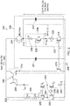
- Figure 2 illustrates a voltage regulator 200 according to an embodiment of the present disclosure.
- the voltage regulator 200 is configured to receive a supply voltage, Vpwr, with a large operating range at a supply terminal 204 and provide a regulated output voltage, V out , at an output terminal 212.
- the regulated output voltage, V out can have a reduced temperature sensitivity with a resulting narrow voltage distribution (in this example, 7.5 V ⁇ 4% at 6 ⁇ ) over a wide range of load current (0 to tens of mA) and for a large supply voltage operating range (10 to 70 V).
- the voltage regulator can also have a low quiescent current.
- the voltage regulator 200 comprises a reference current generator 202 coupled between the supply terminal 204 and the reference terminal 206.
- the reference current generator is configured to provide a reference current, I REF , that is independent of an operating range of the supply voltage.
- I REF a reference current
- the operating range of the supply voltage relates to the range of the supply voltage when the voltage regulator 200 is operating. In this example, the operating range of the supply voltage is 10 V to 70 V.
- the reference current generator 202 comprises a bias resistance 250, a first bipolar transistor, Q 0 , 252, a second bipolar transistor, Q 1 , 254, a third bipolar transistor, Q 2 , 256, a fourth bipolar transistor, Q 3 , 258 and an output current resistor 260.
- the reference current generator 202 comprises NPN bipolar transistors.
- the bias resistance 250, the first to fourth bipolar transistors 252, 254, 256, 258, and the output resistance 260 produce a first reference current, I REF-1 , at a reference current output terminal 266.
- the bias resistance 250 is coupled to the supply terminal 204 and to the reference terminal 206 via the third and fourth bipolar transistors 256, 258.
- the bias resistance 250 is configured to provide a bias current to a collector terminal of the fourth bipolar transistor 258.
- the bias resistance comprises a first bias resistor, R1, and a second bias resistor, R2. If both the first and second bias resistors comprise a resistance value of 20 M ⁇ and the supply voltage, Vpwr, has an operating range that can vary from 10 V to 70 V, then the biasing current provided to the fourth bipolar transistor 258 will vary from 200 nA to 1.75 ⁇ A.
- the first to fourth bipolar transistors are arranged as follows: a collector terminal of the fourth bipolar transistor 258 is connected to the bias resistance 250; the fourth bipolar transistor is arranged in a diode-connected configuration with a base terminal and a collector terminal of the fourth bipolar transistor 258 connected together; an emitter terminal of the fourth bipolar transistor 258 is connected to a collector terminal of the third bipolar transistor 256 at a first node 262; an emitter terminal of the third bipolar transistor 256 is connected to the reference terminal 206; the output current resistor, R i , 260 is coupled between the reference terminal 206 and an emitter terminal of the first bipolar transistor 252; a collector terminal of the first bipolar transistor 252 is connected to an emitter terminal of the second bipolar transistor 254; a collector terminal of the second bipolar transistor 254 is coupled to the reference current output terminal 266; the base terminal of the fourth bipolar transistor 258 is connected to a base terminal of the second bipolar transistor 254; a base terminal of the third bipolar transistor 256
- a ratio of the effective size of the first bipolar transistor 252 to the second, third and fourth bipolar transistors 254, 256, 258 is 8:1:1:1.
- effective size may relate to the size of a component on a semiconductor die.
- an effective size of a bipolar transistor may be increased by stacking multiple bipolar transistors in parallel with common base, collector and emitter terminals.
- I REF ⁇ 1 . R i + VBE Q 0 VBE Q 1 I REF ⁇ 1 . R i + V T . ln I REF ⁇ 1 ⁇ gen .
- V T and I S are the thermal voltage and saturation current respectively of the bipolar transistors.
- the first reference current, I REF-1 depends only on a resistance value, Ri, of the output current resistor 260 and the ratio, ⁇ gen , of the first and second bipolar transistors 252, 254.
- the first reference current, I REF-1 is independent of any variation in the supply voltage, Vpwr, which can be particularly advantageous in battery management systems.
- a temperature dependence of the first reference current, I REF-1 can also be controlled.
- a temperature dependence (or co-efficient) of the first reference current (d/ REF - 1 /dT) will depend on a temperature dependence of the thermal voltage (d V T /dT) and a temperature dependence of the output current resistor 260 (d Ri /dT).
- the reference current generator 202 may provide the first reference current, I REF-1 , to the regulator stage 208 as the reference current.
- an additional high-voltage mirror 268 mirrors the first reference current, I REF-1 , to produce the reference current, I REF .
- the high-voltage mirror is a PMOS mirror, but in other examples it may comprise other components such as PNP transistors.
- the PMOS mirror comprises: a first PMOS transistor with a conduction channel coupled between the supply terminal 204 and the reference current output terminal 266; and a second PMOS transistor with a conduction channel coupled between the supply terminal and a current terminal 210 of the regulator stage 208.
- a gate of the first PMOS transistor is connected to a gate of the second PMOS transistor and the reference current output terminal 266.
- a ratio, ⁇ PMOS of the effective size of the second PMOS transistor to an effective size of the first PMOS transistor is 2:1 such that the reference current, I REF , is double the first reference current, I REF-1 .
- the voltage regulator 200 further comprises a regulator stage 208.
- the regulator stage 208 comprises a current terminal 210 which receives the reference current, I REF , from the reference current generator 202, a NMOS transistor 214, an input bipolar transistor 216, an output bipolar transistor 218 and a first output resistor 220.
- the first output resistor 220 and the conduction channel of the output bipolar transistor 218 are coupled in series between the output terminal 212 and the reference terminal 206 forming at least part of a voltage reference circuit 222 for providing the regulated output voltage, V out .
- the input bipolar transistor 216 and output bipolar transistor 218 form a bipolar current mirror.
- the NMOS transistor 214, the bipolar current mirror 216, 218 and the first output resistor 220 are arranged in a negative feedback loop to pull a mirrored reference current from the NMOS transistor 214 through the first output resistor 220 and the output bipolar transistor 218.
- the NMOS transistor 214 has a gate terminal coupled to the current terminal 210, a drain terminal coupled to the supply terminal 204, and a source terminal coupled to the output terminal 212.
- the NMOS transistor 214 can have a voltage rating higher than a maximum value of the operating range of the supply voltage, Vpwr.
- the voltage reference circuit 222 coupled between the output terminal 212 and the reference terminal 206, comprises the first output resistor 220 coupled in series with a conduction channel of the output bipolar transistor 218.
- the output bipolar transistor 218 is arranged in a diode connected configuration with a base terminal connected to a first conduction channel terminal (collector terminal for a NPN transistor).
- a first conduction channel terminal of the output bipolar transistor 218 is coupled to the reference terminal 206 and a second conduction channel terminal of the output bipolar transistor 218 is coupled to a first end of the first output resistor 220.
- a second end of the first output resistor 220 is coupled to the output terminal 212 either directly or via one or more further voltage reference blocks 224.
- a conduction channel of the input bipolar transistor 216 is coupled between the current terminal 210 and the reference terminal 206.
- a base terminal of the input bipolar transistor 216 is coupled to a base terminal of the output bipolar transistor 218 forming a bipolar current mirror.
- the bipolar current mirror can mirror the reference current, I REF , to produce a mirrored reference current in the voltage reference circuit 222.
- the bipolar current mirror may pull a mirrored reference current from the NMOS transistor 214 through the voltage reference circuit 222 to the reference terminal 206.
- An effective size of the output bipolar transistor 218 may be different to an effective size of the input bipolar transistor 216.
- effective size may relate to the size of a component on a semiconductor die.
- an effective size of a bipolar transistor may be increased by stacking multiple bipolar transistors in parallel with common base, collector and emitter terminals.
- a ratio, ⁇ reg of the effective size of the output bipolar transistor 218 to the effective size of the input bipolar transistor is 4:1.
- the mirrored reference current can be 4 times larger than the reference current, I REF .
- the bipolar current mirror 216, 218 and the NMOS transistor 214 create a negative feedback loop forcing four times the reference current, I REF , through the voltage reference circuit as the mirrored reference current.
- the input bipolar transistor 216 and output bipolar transistor 218 are NPN transistors.
- the nature (or type) of the bipolar transistors 216, 218 and the first output resistor 220 of the regulator stage 208 can be respectively the same as the bipolar transistors 252, 254, 256, 258 and the output current resistor 260 of the reference current generator 202.
- the bipolar transistors and resistors of the regulator stage 208 can be matched to the bipolar transistors and resistors used in the reference current generator 202.
- This matching can comprise the bipolar transistors and resistors sharing the same nature or type (NPN/PNP transistors, polyfused, metal layer etc resistors), same temperature coefficient / same temperature dependence, same fabrication process, same wafer, same time of manufacture, and / or same location on the layout, as is known in the art.
- This matching of the components of the regulator 208 and reference current generator 202 can compensate process variations and provide the same component temperature dependence. For example, any process variation in the components of the reference current generator 202 that leads to a variation in the nominal reference current, or a temperature dependence thereof, will be compensated by corresponding process variation in the components of the regulator stage 208.
- the input and output bipolar transistors 216, 218 and the first to fourth bipolar transistors 252, 254, 256, 258 all share the same type.
- all of the bipolar transistors share the same temperature coefficient of their collector-emitter voltage, dV CE / dT, (or base-emitter voltage, d V BE /dT).
- the first output resistor 228 and output current resistor 260 are of the same type and their resistances, R, Ri, share the same temperature coefficient (d R /dT).
- the collector-emitter voltage, V CE , across the output bipolar transistor 218 in the diode-connected configuration is equal to the base-emitter voltage, V BE .
- the collector-emitter voltage, V CE (or the base-emitter voltage, V BE , in a diode configuration) can comprise a fixed bandgap voltage and a complementary to absolute temperature, CTAT, voltage component, which has an inverse relationship with temperature.
- CTAT absolute temperature
- the NPN output bipolar transistor 218 arranged in a diode connected configuration has a fixed bandgap voltage of -1.25 V.
- V out R ⁇ ⁇ reg ⁇ I REF ⁇ PTAT + V CE ⁇ CTAT
- R is a resistance value of the first output resistor 220.
- the reference current, I REF is proportional to the thermal voltage, V T , of the bipolar transistors of the reference current generator 202, divided by the resistance, R i , of the output current resistor 260.
- the temperature dependence of the first term of the above equation depends on the temperature dependence of the thermal voltage, V T , which is a positive constant. Therefore, the first term of the equation defines a PTAT voltage source.
- the regulated output voltage, V out comprises a sum of a PTAT voltage source and a CTAT voltage source. Therefore, the resistance value, R , of the first output resistor 220 can be selected to compensate the temperature coefficient of the voltage, V CE ( V BE in this example), across the output bipolar transistor 218. As a result, the contribution of the diode-connected output bipolar transistor 218 and the first output resistor 220 to the regulated output voltage, V out , can be insensitive to temperature variations and equal to the fixed bandgap voltage of 1.25 V. Therefore, the voltage reference circuit 222 of the voltage regulator 200 can provide a temperature independent regulated output voltage, V out .
- the resistance value, R , of the first output resistor 220 may be based on the resistance, Ri , of the output current resistor 260, the effective size ratio, ⁇ gen , of the first bipolar transistor 252 and the second bipolar transistor 254, the effective size ratio, ⁇ PMOS , of the PMOS current mirror 268 (where applicable), the effective size ratio, ⁇ reg , of the bipolar current mirror 216, 218, the temperature coefficient of the thermal voltage, V T , of the bipolar transistors of the reference current generator 202 and a temperature co-efficient (d V CE /dT) of the collector-emitter voltage across the output bipolar transistor 216.
- the resistance value, R , of the first output resistor 220 can be selected to balance the CTAT voltage component of the output bipolar resistor based on the resistance, Ri , of the output current resistor 260, the temperature co-efficient (d V T /dT) of the thermal voltage, the temperature coefficient (d V CE /dT) of the collector-emitter voltage of the output bipolar transistor and, where applicable, scaling ratios ( ⁇ reg , ⁇ PMOS , In( ⁇ gen )) of the voltage regulator 200. Equivalently, a ratio of the resistances R/Ri can also be selected.
- each of: the resistance value, R, of the first output resistor 220; the resistance, Ri, of the output current resistor 260; and the scaling ratios ( ⁇ reg , ⁇ PMOS , In( ⁇ gen )) of the voltage regulator 200, can be selected to balance the CTAT voltage component of the output bipolar transistor.
- the resistance value, R of the first output resistor 220
- the resistance, Ri of the output current resistor 260
- the scaling ratios ( ⁇ reg , ⁇ PMOS , In( ⁇ gen )) of the voltage regulator 200 can be selected to balance the CTAT voltage component of the output bipolar transistor.
- the output voltage, Vout, of the voltage regulator 200 can be insensitive to temperature variations.
- the voltage regulator 200 can provide an output voltage, V out , with high accuracy that is insensitive to any variation in process or environment.
- the regulator stage 208 further comprises a feedback capacitor 221 coupled between the gate of the NMOS transistor 214 and the reference terminal 206.
- the feedback capacitor 221 can provide stability to the voltage regulator 200.
- the regulator stage 208 also comprises an output capacitor 223 coupled between the output terminal 212 and the reference terminal 206. Both the feedback capacitor 221 and the output capacitor 223 are on the order of a few picofarads and can be integrated on-chip.
- the low impedance provided by the presence of the NMOS transistor 214 at the output terminal 212 enables such low capacitances to be used while maintaining a stable circuit, particularly in response to changes in load.
- the voltage reference circuit 222 may only comprise the output bipolar transistor 218 and the first output transistor 220. In this way, the voltage reference circuit 222 can provide a temperature regulated output voltage, V out , equal to the fixed bandgap voltage of the output bipolar transistor 218. In other examples, where a higher output voltage is required, the voltage reference circuit 222 may comprise one or more further voltage reference blocks 224.
- Each further voltage reference block 224 may comprise a further bipolar transistor 226 and a further output resistor 228.
- the further bipolar transistor 226 may be substantially the same as the output bipolar transistor and be of the same type.
- the further bipolar transistor 226 of each further voltage reference block 224 comprises a NPN bipolar transistor that is nominally the same as the output bipolar transistor 218.
- the further bipolar transistor 226 is arranged in a diode-connected configuration, however in other examples, one or more further bipolar transistors 226 may be connected in other configurations, as illustrated in Figures 4 and 5 .
- the further output resistor 228 may be substantially the same as the first output resistor 220, being of the same type (polyfused, metal film etc) and may have the same resistance value, R.
- each further resistor 228 can balance the CTAT component of the collector-emitter voltage, V CE , across the respective further bipolar transistor 226 providing a temperature independent contribution to the regulated output voltage, V out .
- each of the one or more further voltage reference blocks 224 can provide an additional temperature independent contribution to the output voltage, V out .
- each further voltage reference block can provide an additional 1.25 V contribution to the output voltage, Vout.
- the five further voltage reference blocks are shown expanded out.
- Each further voltage reference block comprises a further output resistor 328-1, 328-2,..328-5 and a further diode-connected bipolar transistor 326-1, 326-2,..326-5 nominally identical to the first output resistor 320 and the output bipolar transistor 318 respectively.
- one or more further bipolar transistors may be arranged in configurations other than a diode-connected configuration.
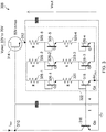
- Figure 4 illustrates a further voltage reference block 424 with a further bipolar transistor 426 connected in a resistor divider configuration according to further embodiments of the present disclosure.
- the further voltage reference block 424 comprises a further output resistor 428 coupled in series with a conduction channel of the further bipolar transistor 426 as described above in relation to Figures 2 and 3 .
- the further voltage reference block 424 comprises: a first division resistor, Ra, 430, coupled between a base terminal of the further bipolar transistor 426 and a first conduction channel terminal of the further bipolar transistor 426; and a second division resistor, Rb, 432, coupled between the base terminal of the further bipolar transistor 426 and a second conduction channel terminal of the further bipolar transistor 426.
- the illustrated resistor divider configuration may be described as a k*VBE structure as it can supply any voltage higher than the fixed bandgap reference voltage of 1.25 V.
- the further voltage reference block 424 can provide a collector-emitter voltage, V CE , proportional to the base-emitter voltage, V BE , and greater than or equal to the classic diode-connected configuration illustrated in Figures 2 and 3 which provides 1.25 V.
- the resistance value, R f , of the further output resistor 428 can be selected to compensate the CTAT coefficient of the collector emitter voltage, V CE , of the further bipolar transistor 426.
- the equations and dependencies outlined above for determining the value of the first output resistor generally apply to determining the resistance value of the further output resistor 428.
- each further bipolar transistor 426 and each further output resistor 428 is otherwise respectively matched to the output bipolar transistor and the first output resistor and also respectively matched to the bipolar transistors and the output current resistor of the reference current generator.
- the further voltage reference block 424 can provide a temperature and process independent regulated output voltage of any value greater than 1.25 V.
- Figure 5 illustrates another voltage regulator 500 according to an embodiment of the present disclosure.
- Features of Figure 5 that are also shown in Figure 2 have been given corresponding reference numbers in the 500 series and will not necessarily be described again here.
- the voltage reference circuit 522 comprises a bipolar output transistor 518 arranged in a diode-connected configuration and a first output resistor 520.
- Each further bipolar transistor 526 is arranged in the resistor divider configuration of Figure 4 .
- the voltage regulator 500 of Figure 5 may therefore provide a versatile range of temperature independent output voltages by suitable selection of Ra, Rb and N.
- the disclosed voltage regulators of Figures 2 and 5 can have a very low total quiescent current, even at high operating voltages of the supply voltage.
- the quiescent current is also independent of the load current.
- the quiescent current comprises contributions from the four branches of the circuits of Figures 2 and 5 :
- the voltage regulators of Figures 2 and 5 can have a maximum quiescent current of approximately 15 ⁇ A for a load current of 0 to 20 mA.
- the quiescent current is also independent of any load current.
- the high-voltage NMOS transistor, the input bipolar transistor and the voltage reference circuit form a closed-loop regulator stage of the voltage regulator.
- the input bipolar transistor and the voltage reference circuit can be considered as a feedback network.
- the feedback network may also comprise the feedback capacitor.
- the feedback network can be matched with the reference current generator.
- the bipolar transistors and resistors of the regulator stage can be matched to the bipolar transistors and resistors used in the reference current generator.
- This matching can comprise the bipolar transistors and resistors sharing the same type (NPN/PNP transistors, polyfused, metal layer etc resistors), same temperature dependence, same fabrication process, same wafer, same time of manufacture, and / or same location on the layout, as is known in the art.
- This matching of the feedback network to the reference current generator can compensate process variations and provide the same component temperature dependence. For example, any process variation in the components of the reference current generator that leads to a variation in the nominal reference current will be compensated by corresponding process variation in the components of the regulator stage.
- the negative feedback loop provided by the NMOS transistor and the feedback network can pull a large current from the supply terminal, through the NMOS transistor, maintaining a fixed regulator output voltage, V out , over a wide range of load currents (up to tens of mA) with a high degree of accuracy.
- the voltage regulator of Figure 2 can maintain a regulated output voltage and distribution/accuracy of 7.5 V ⁇ 4% at 6 ⁇ .
- the accurate output voltage can be provided without requiring output trimming.
- the disclosed voltage regulators provide a low impedance output which can enable a fast-transient response to strong line regulation or load regulation variations. If a load current decreases in a step-wise manner then the negative feedback loop of the regulator stage can rapidly respond to maintain the regulated output voltage, V out .
- the low impedance output can also have reduced sensitivity to variations in load mismatch.
- the disclosed voltage regulators also provide a high-value power supply rejection ratio (PSSR) maintaining the accurate regulated output voltage distribution over a wide operating range of the supply voltage, Vpwr.
- PSSR power supply rejection ratio
- the high PSSR can be maintained as long as the high-voltage NMOS transistor and the high-voltage PMOS current mirror (discussed below) have sufficient saturation margin.
- the disclosed voltage regulators comprise an arrangement of:
- the disclosed voltage regulators can be considered as self-referenced and self-biased voltage regulators with a minimal quiescent current that is independent from any load current.
- the voltage regulators can provide an accurate regulated output voltage over a wide load current and / or power supply voltage range.
- the disclosed voltage regulators can be used in any power management IC operating in an environment with a wide operating range of input/supply voltage.
- the disclosed voltage regulators can be particularly advantageous in applications where current consumption is critical (particularly at low loads).
- the disclosed voltage regulators may find particularly advantageous application in battery management systems, such as battery management systems for electric or hybrid vehicles.
- the voltage regulators can support a wide range of high-power supply voltages while delivering minimal low power mode current consumption. Moreover, the robustness and accuracy of the voltage regulator can simplify downstream voltage regulator stages and save die-size.
- the set of instructions/method steps described above are implemented as functional and software instructions embodied as a set of executable instructions which are effected on a computer or machine which is programmed with and controlled by said executable instructions. Such instructions are loaded for execution on a processor (such as one or more CPUs).
- processor includes microprocessors, microcontrollers, processor modules or subsystems (including one or more microprocessors or microcontrollers), or other control or computing devices.
- a processor can refer to a single component or to plural components.
- the set of instructions/methods illustrated herein and data and instructions associated therewith are stored in respective storage devices, which are implemented as one or more non-transient machine or computer-readable or computer-usable storage media or mediums.
- Such computer-readable or computer usable storage medium or media is (are) considered to be part of an article (or article of manufacture).
- An article or article of manufacture can refer to any manufactured single component or multiple components.
- the non-transient machine or computer usable media or mediums as defined herein excludes signals, but such media or mediums may be capable of receiving and processing information from signals and/or other transient mediums.
- Example embodiments of the material discussed in this specification can be implemented in whole or in part through network, computer, or data based devices and/or services. These may include cloud, internet, intranet, mobile, desktop, processor, look-up table, microcontroller, consumer equipment, infrastructure, or other enabling devices and services. As may be used herein and in the claims, the following non-exclusive definitions are provided.
- one or more instructions or steps discussed herein are automated.
- the terms automated or automatically mean controlled operation of an apparatus, system, and/or process using computers and/or mechanical/electrical devices without the necessity of human intervention, observation, effort and/or decision.
- any components said to be coupled may be coupled or connected either directly or indirectly.
- additional components may be located between the two components that are said to be coupled.
Landscapes
- Engineering & Computer Science (AREA)
- Physics & Mathematics (AREA)
- Microelectronics & Electronic Packaging (AREA)
- Electromagnetism (AREA)
- General Physics & Mathematics (AREA)
- Radar, Positioning & Navigation (AREA)
- Automation & Control Theory (AREA)
- Nonlinear Science (AREA)
- Power Engineering (AREA)
- Control Of Electrical Variables (AREA)
Abstract
Description
- The present disclosure relates to a voltage regulator and in particular to a voltage regulator for a battery management system.
- According to a first aspect of the present disclosure there is provided a voltage regulator comprising:
- a supply terminal configured to receive a supply voltage;
- a reference terminal;
- an output terminal configured to provide a regulated output voltage;
- a reference current generator coupled between the supply terminal and the reference terminal and configured to provide a reference current that is independent of an operating range of the supply voltage; and
- a regulator stage comprising:
- a current terminal configured to receive the reference current from the reference current generator;
- a NMOS transistor having:
- a gate terminal coupled to the current terminal;
- a drain terminal coupled to the supply terminal; and
- a source terminal coupled to the output terminal;
- a voltage reference circuit coupled between the output terminal and the reference terminal and configured to provide the regulated output voltage, the voltage reference circuit comprising a first output resistor coupled in series with a conduction channel of an output bipolar transistor, wherein the output bipolar transistor is arranged in a diode-connected configuration;
- an input bipolar transistor having: a conduction channel coupled between the current terminal and the reference terminal; and a base terminal coupled to a base terminal of the output bipolar transistor such that the input bipolar transistor and the output bipolar transistor form a bipolar current mirror for mirroring the reference current through the voltage reference circuit.
- The disclosed voltage regulators provide a low impedance output which can enable a fast-transient response to strong line regulation or load regulation variations. If a load current decreases in a step-wise manner then the negative feedback loop of the regulator stage can rapidly respond to maintain the regulated output voltage. The low impedance output can also have reduced sensitivity to variations in load mismatch.
- The NMOS transistor, the bipolar current mirror and the first output resistor may be arranged in a negative feedback loop and configured to pull a mirrored reference current from the NMOS transistor through the first output resistor and the output bipolar transistor.
- The negative feedback loop can pull a large current from the supply terminal, through the NMOS transistor, maintaining a fixed regulator output voltage over a wide range of load currents (up to tens of mA) with a high degree of accuracy.
- In one or more embodiments the input bipolar transistor and the output bipolar transistor may be matched to bipolar transistors of the reference current generator. The first output resistor may be matched to an output current resistor of the reference current generator.
- Matching the bipolar transistors and resistors of the reference current generator and the regulator stage can provide an output voltage with high accuracy that is insensitive to any variation in process, temperature or environment.
- In one or more embodiments the input bipolar transistor and the output bipolar transistor may be matched to the bipolar transistors of the reference current generator by each transistor sharing one or more of: a same type, a same temperature coefficient, a same fabrication process, a same wafer, a same time of manufacture and / or a same location on the layout. The first output resistor may be matched to the output current resistor of the reference current generator by each resistor sharing one or more of: a same type, a same temperature coefficient, a same fabrication process, a same wafer, a same time of manufacture and / or a same location on the layout.
- In one or more embodiments a resistance of the first output resistor may be selected such that a voltage across the first output resistor upon receipt of a mirrored reference current compensates a complementary to absolute temperature, CTAT, voltage component of the output bipolar transistor.
- In one or more embodiments a ratio of an effective size of the output bipolar transistor to an effective size of the input bipolar transistor may be selected such that a voltage across the first output resistor upon receipt of the mirrored reference current compensates a complementary to absolute temperature, CTAT, voltage component of the output bipolar transistor.
- In one or more embodiments the voltage reference circuit may comprise one or more further voltage reference blocks coupled in series with the first output resistor and the output bipolar transistor between the output terminal and the reference terminal. Each further voltage reference block may comprise:
- a further output resistor; and
- a further bipolar transistor arranged having a conduction channel connected in series with the further output resistor.
- In one or more embodiments the further bipolar transistor may be arranged in a diode connected configuration.
- In one or more embodiments the further voltage reference block may comprise:
- a first further division resistor coupled between a base terminal of the further bipolar transistor and a first conduction channel terminal of the further bipolar transistor; and
- a second further division resistor coupled between the base terminal of the further bipolar transistor and a second conduction channel terminal of the further bipolar transistor.
- In one or more embodiments a resistance of each further output resistor may be selected such that a voltage across the further output resistor upon receipt of a mirrored reference current compensates a complementary to absolute temperature, CTAT, voltage component of the corresponding further bipolar transistor.
- In one or more embodiments each further bipolar transistor may be matched to the output bipolar transistor and bipolar transistors of the reference current generator. Each further output resistor may be matched to the first output resistor and an output current resistor of the reference current generator.
- In one or more embodiments each further bipolar transistor may be matched to the output bipolar transistor and bipolar transistors of the reference current generator by each transistor sharing one or more of: a same type, a same temperature coefficient, a same fabrication process, a same wafer, a same time of manufacture and / or a same location on the layout. Each further output resistor may be matched to the first output resistor and an output current resistor of the reference current generator by each resistor sharing one or more of: a same type, a same temperature coefficient, a same fabrication process, a same wafer, a same time of manufacture and / or a same location on the layout.
- In one or more embodiments the further bipolar transistor may be a NPN bipolar transistor
- In one or more embodiments the input bipolar transistor and the output bipolar transistors may be NPN bipolar transistors.
- In one or more embodiments the reference current generator may comprise:
- a bias resistance;
- a first bipolar transistor;
- a second bipolar transistor;
- a third bipolar transistor;
- a fourth bipolar transistor; and
- an output current resistor,
- the bias resistance is coupled to the supply terminal and configured to provide a bias current to a conduction channel of the fourth bipolar transistor;
- the conduction channel of the fourth bipolar transistor is connected between the bias resistance and a first node;
- a conduction channel of the third bipolar transistor is connected between the first node and the reference terminal;
- the output current resistor is coupled between the reference terminal and a conduction channel of the first bipolar transistor;
- the conduction channel of the first bipolar transistor is connected between the output current resistor and a second node;
- a conduction of the second bipolar transistor is coupled between the second node and a reference current output terminal;
- a base terminal of the fourth bipolar transistor is connected to a base terminal of the second bipolar transistor;
- a base terminal of the third bipolar transistor is connected to the second node;
- a base terminal of the first bipolar transistor is connected to the first node; and
- the fourth bipolar transistor is arranged in a diode connected configuration.
- In one or more embodiments a resistance value of the first output resistor may be based on a resistance value of the output current resistor and a temperature co-efficient of a collector-emitter voltage of the output bipolar transistor.
- In one or more embodiments a resistance value of the first output resistor may be based on a resistance value of the output current resistor, a ratio of an effective size of the input bipolar transistor to an effective size of the output bipolar transistor, a ratio of an effective size of the first bipolar transistor to an effective size of the second bipolar transistor, a temperature coefficient of a thermal voltage of the first bipolar transistor and a temperature co-efficient of a collector-emitter voltage of the output bipolar transistor.
- In one or more embodiments a resistance value of each further output resistor may be based on a resistance value of the output current resistor and a temperature co-efficient of a collector-emitter voltage of the corresponding further bipolar transistor.
- In one or more embodiments a resistance value of each further output resistor is based on a resistance value of the output current resistor, a ratio of an effective size of the input bipolar transistor to an effective size of the output bipolar transistor, a ratio of an effective size of the first bipolar transistor to an effective size of the second bipolar transistor, a temperature coefficient of a thermal voltage of the first bipolar transistor and a temperature co-efficient of a collector-emitter voltage of the corresponding further bipolar transistor.
- In one or more embodiments the reference current generator may further comprise a PMOS mirror configured to mirror the reference current from the reference current output terminal to the regulator stage.
- In one or more embodiments a resistance value of the first output resistor and any further output resistors are further based on an effective size ratio of the PMOS current mirror.
- In one or more embodiments the first to fourth bipolar transistors may be NPN bipolar transistors.
- In one or more embodiments, based on a temperature coefficient of the output current resistor, the reference current generator may be one of:
- a proportional to absolute temperature, PTAT, current generator;
- a complementary to absolute temperature, CTAT, current generator; and
- a temperature independent current generator.
- In one or more embodiments effective sizes of the second, third and fourth bipolar transistors may be substantially the same.
- In one or more embodiments an effective size of the first bipolar transistor may be greater than the effective size of the second bipolar transistor.
- In one or more embodiments the regulator stage may further comprise a feedback capacitor coupled between the gate of the NMOS transistor and the reference terminal.
- In one or more embodiments the voltage regulator may further comprise an output capacitor coupled between the output terminal and the reference terminal.
- According to a second aspect of the present disclosure there is provided a battery management system comprising any of the voltage regulators disclosed herein.
- According to a further aspect of the present disclosure there is provided a voltage regulator comprising:
- a supply terminal configured to receive a supply voltage;
- a reference terminal;
- an output terminal configured to provide a regulated output voltage;
- a reference current generator coupled between the supply terminal and the reference terminal and configured to provide a reference current that is independent of an operating range of the supply voltage; and
- a regulator stage configured to receive the reference current from the reference current generator, the regulator stage comprising:
- a NMOS transistor with a conduction channel coupled between the supply terminal and the output terminal;
- a bipolar current mirror; and
- a first output resistor,
- While the disclosure is amenable to various modifications and alternative forms, specifics thereof have been shown by way of example in the drawings and will be described in detail. It should be understood, however, that other embodiments, beyond the particular embodiments described, are possible as well. All modifications, equivalents, and alternative embodiments falling within the spirit and scope of the appended claims are covered as well.
- The above discussion is not intended to represent every example embodiment or every implementation within the scope of the current or future Claim sets. The figures and Detailed Description that follow also exemplify various example embodiments. Various example embodiments may be more completely understood in consideration of the following Detailed Description in connection with the accompanying Drawings.
- One or more embodiments will now be described by way of example only with reference to the accompanying drawings in which:
-
Figure 1 shows distributions of a regulated output voltage of a pre-regulator with and without over-voltage and under-voltage detection requirements; -
Figure 2 shows a voltage regulator according to an example embodiment of the present disclosure; -
Figure 3 shows another voltage regulator according to an example embodiment of the present disclosure; -
Figure 4 shows a further voltage reference block according to an example embodiment of the present disclosure; and -
Figure 5 shows a further voltage regulator according to an example embodiment of the present disclosure. - Integrated circuits (IC) operating in a high-voltage environment with a large input power supply operating range can require a first voltage regulator, or pre-regulator, to enable optimisation of subsequent regulator stages such as the optimisation of die-size area through the use of low voltage devices. One such environment is a battery management system (BMS) for electric and hybrid vehicles.
- Requirements of the pre-regulator may include a very low current consumption to support IC sleep mode current consumption, while being able to provide a large load current range when the IC is in full power mode.
- The regulated output voltage of the pre-regulator may also have stringent accuracy requirements over variations in temperature, process, input/supply voltage and load to support minimum load voltage requirements and maximum voltage rating (to allow design of load functions with low voltage devices).
- In some applications, such as a BMS, safety can also be a mandatory requirement, and pre-regulator output voltage monitoring can be required. This can include detection of over-voltage and under-voltage. As a result, a distribution range of over-voltage and under-voltage over process, temperature, voltage and mismatch should not overlap with the distribution of the pre-regulator output voltage in order to prevent false error detection. In other words, the over-voltage and under-voltage distributions should be independent of the pre-regulator's regulated output voltage distribution and all three distributions should fit between a maximum voltage rating limit and a minimum load voltage.
-
Figure 1 illustrates distributions of aregulated output voltage regulated output voltage 103 of the pre-regulator is only required to lie between amaximum voltage rating 105 and aminimum voltage rating 107 for functionality, centred on anominal output voltage 109. The right-hand plot illustrates the distribution requirements of a pre-regulator with safety requirements for over and under- voltage regulation. An example of such requirements is Automotive Safety Integrity Level D (ASIL-D) required for BMS. The required distribution of theregulated output voltage 101, centred on thenominal output voltage 109 is much narrower to enable room for an over-voltage distribution 111 and an under-voltage distribution 113 between the upper andlower ratings distributions 101, 111, 113. Obtaining such an accurate distribution ofregulated output voltage 101 can be challenging when no reference voltage or biasing current are available. This can be particularly challenging in high-voltage environments requiring a low power output for downstream regulators, such as in BMS. - Voltage regulators of the present disclosure can address the stringent requirements outlined above and provide a regulated output voltage with a narrow distribution over temperature, supply voltage and load. The regulators can provide up to tens of mA of load current and have a low quiescent current less than 15 µA.
-
Figure 2 illustrates avoltage regulator 200 according to an embodiment of the present disclosure. - The
voltage regulator 200 is configured to receive a supply voltage, Vpwr, with a large operating range at asupply terminal 204 and provide a regulated output voltage, Vout, at anoutput terminal 212. The regulated output voltage, Vout, can have a reduced temperature sensitivity with a resulting narrow voltage distribution (in this example, 7.5 V ± 4% at 6σ) over a wide range of load current (0 to tens of mA) and for a large supply voltage operating range (10 to 70 V). The voltage regulator can also have a low quiescent current. - The
voltage regulator 200 comprises a referencecurrent generator 202 coupled between thesupply terminal 204 and thereference terminal 206. The reference current generator is configured to provide a reference current, IREF, that is independent of an operating range of the supply voltage. The operating range of the supply voltage relates to the range of the supply voltage when thevoltage regulator 200 is operating. In this example, the operating range of the supply voltage is 10 V to 70 V. - In this example, the reference
current generator 202 comprises abias resistance 250, a first bipolar transistor, Q0 , 252, a second bipolar transistor, Q1 , 254, a third bipolar transistor, Q2 , 256, a fourth bipolar transistor, Q3 , 258 and an outputcurrent resistor 260. In this example, the referencecurrent generator 202 comprises NPN bipolar transistors. Thebias resistance 250, the first to fourthbipolar transistors output resistance 260 produce a first reference current, IREF-1, at a referencecurrent output terminal 266. - The
bias resistance 250 is coupled to thesupply terminal 204 and to thereference terminal 206 via the third and fourthbipolar transistors bias resistance 250 is configured to provide a bias current to a collector terminal of the fourthbipolar transistor 258. In this example, the bias resistance comprises a first bias resistor, R1, and a second bias resistor, R2. If both the first and second bias resistors comprise a resistance value of 20 MΩ and the supply voltage, Vpwr, has an operating range that can vary from 10 V to 70 V, then the biasing current provided to the fourthbipolar transistor 258 will vary from 200 nA to 1.75 µA. - The first to fourth bipolar transistors are arranged as follows: a collector terminal of the fourth bipolar transistor 258 is connected to the bias resistance 250; the fourth bipolar transistor is arranged in a diode-connected configuration with a base terminal and a collector terminal of the fourth bipolar transistor 258 connected together; an emitter terminal of the fourth bipolar transistor 258 is connected to a collector terminal of the third bipolar transistor 256 at a first node 262; an emitter terminal of the third bipolar transistor 256 is connected to the reference terminal 206; the output current resistor, Ri , 260 is coupled between the reference terminal 206 and an emitter terminal of the first bipolar transistor 252; a collector terminal of the first bipolar transistor 252 is connected to an emitter terminal of the second bipolar transistor 254; a collector terminal of the second bipolar transistor 254 is coupled to the reference current output terminal 266; the base terminal of the fourth bipolar transistor 258 is connected to a base terminal of the second bipolar transistor 254; a base terminal of the third bipolar transistor 256 is connected to the emitter terminal of the second bipolar transistor 254 and the collector terminal of the first bipolar transistor 252 at the second node 262; and a base terminal of the first bipolar transistor 252 is connected to the emitter terminal of the fourth bipolar transistor 258 and the collector terminal of the third bipolar transistor 256 at the first node 260.
- In this example, a ratio of the effective size of the first
bipolar transistor 252 to the second, third and fourthbipolar transistors - Kirchoff's voltage law allows us to define the first reference output current, IREF-1, in terms of the base-emitter voltages, VBEQ, of the first to fourth
bipolar transistors 
- Assuming the base current of the bipolar transistors is negligible compared to the biasing current and the first reference current, we get:


bipolar transistor 252 to the effective size of the second bipolar transistor 254 (ϕgen = 8 in this example). Therefore, the first reference current, IREF-1, depends only on a resistance value, Ri, of the outputcurrent resistor 260 and the ratio, ϕgen, of the first and secondbipolar transistors - In addition to being independent of the supply voltage, Vpwr, a temperature dependence of the first reference current, IREF-1, can also be controlled. A temperature dependence (or co-efficient) of the first reference current (d/ REF-1 /dT) will depend on a temperature dependence of the thermal voltage (dVT /dT) and a temperature dependence of the output current resistor 260 (dRi/dT). The temperature dependence of the thermal voltage is typically a positive constant (VT=kbT/q (26mV @25°C)). Therefore, the reference
current generator 202 providing the first reference current, IREF-1, and reference current, IREF, can be one of: (i) a proportional to absolute temperature, PTAT, current generator; (ii) a complementary to absolute temperature, CTAT, current generator; or a temperature independent current generator, depending on the relative values of dRi /dT and dVT /dT. For example, if the outputcurrent resistor 260 is temperature independent (dRi/dT = 0), the referencecurrent generator 202 will be a PTAT current generator. - The reference
current generator 202 may provide the first reference current, IREF-1, to theregulator stage 208 as the reference current. In this example, an additional high-voltage mirror 268 mirrors the first reference current, IREF-1, to produce the reference current, IREF. In this example, the high-voltage mirror is a PMOS mirror, but in other examples it may comprise other components such as PNP transistors. The PMOS mirror comprises: a first PMOS transistor with a conduction channel coupled between thesupply terminal 204 and the referencecurrent output terminal 266; and a second PMOS transistor with a conduction channel coupled between the supply terminal and acurrent terminal 210 of theregulator stage 208. A gate of the first PMOS transistor is connected to a gate of the second PMOS transistor and the referencecurrent output terminal 266. In this example, a ratio, ϕPMOS, of the effective size of the second PMOS transistor to an effective size of the first PMOS transistor is 2:1 such that the reference current, IREF, is double the first reference current, IREF-1. - The
voltage regulator 200 further comprises aregulator stage 208. Theregulator stage 208 comprises acurrent terminal 210 which receives the reference current, IREF, from the referencecurrent generator 202, aNMOS transistor 214, an inputbipolar transistor 216, an outputbipolar transistor 218 and afirst output resistor 220. Thefirst output resistor 220 and the conduction channel of the outputbipolar transistor 218 are coupled in series between theoutput terminal 212 and thereference terminal 206 forming at least part of avoltage reference circuit 222 for providing the regulated output voltage, Vout. The inputbipolar transistor 216 and outputbipolar transistor 218 form a bipolar current mirror. TheNMOS transistor 214, the bipolarcurrent mirror first output resistor 220 are arranged in a negative feedback loop to pull a mirrored reference current from theNMOS transistor 214 through thefirst output resistor 220 and the outputbipolar transistor 218. - The
NMOS transistor 214 has a gate terminal coupled to thecurrent terminal 210, a drain terminal coupled to thesupply terminal 204, and a source terminal coupled to theoutput terminal 212. TheNMOS transistor 214 can have a voltage rating higher than a maximum value of the operating range of the supply voltage, Vpwr. - The
voltage reference circuit 222, coupled between theoutput terminal 212 and thereference terminal 206, comprises thefirst output resistor 220 coupled in series with a conduction channel of the outputbipolar transistor 218. In this example, the outputbipolar transistor 218 is arranged in a diode connected configuration with a base terminal connected to a first conduction channel terminal (collector terminal for a NPN transistor). - In this example, a first conduction channel terminal of the output
bipolar transistor 218 is coupled to thereference terminal 206 and a second conduction channel terminal of the outputbipolar transistor 218 is coupled to a first end of thefirst output resistor 220. A second end of thefirst output resistor 220 is coupled to theoutput terminal 212 either directly or via one or more further voltage reference blocks 224. - A conduction channel of the input
bipolar transistor 216 is coupled between thecurrent terminal 210 and thereference terminal 206. A base terminal of the inputbipolar transistor 216 is coupled to a base terminal of the outputbipolar transistor 218 forming a bipolar current mirror. In this way, the bipolar current mirror can mirror the reference current, IREF, to produce a mirrored reference current in thevoltage reference circuit 222. In other words, the bipolar current mirror may pull a mirrored reference current from theNMOS transistor 214 through thevoltage reference circuit 222 to thereference terminal 206. - An effective size of the output
bipolar transistor 218 may be different to an effective size of the inputbipolar transistor 216. Here, effective size may relate to the size of a component on a semiconductor die. For example, an effective size of a bipolar transistor may be increased by stacking multiple bipolar transistors in parallel with common base, collector and emitter terminals. In this example, a ratio, ϕreg, of the effective size of the outputbipolar transistor 218 to the effective size of the input bipolar transistor is 4:1. As a result, the mirrored reference current can be 4 times larger than the reference current, IREF. In this way, the bipolarcurrent mirror NMOS transistor 214 create a negative feedback loop forcing four times the reference current, IREF, through the voltage reference circuit as the mirrored reference current. - In the illustrated example, the input
bipolar transistor 216 and outputbipolar transistor 218 are NPN transistors. In one or more examples, the nature (or type) of thebipolar transistors first output resistor 220 of theregulator stage 208 can be respectively the same as thebipolar transistors current resistor 260 of the referencecurrent generator 202. In other words, the bipolar transistors and resistors of theregulator stage 208 can be matched to the bipolar transistors and resistors used in the referencecurrent generator 202. This matching can comprise the bipolar transistors and resistors sharing the same nature or type (NPN/PNP transistors, polyfused, metal layer etc resistors), same temperature coefficient / same temperature dependence, same fabrication process, same wafer, same time of manufacture, and / or same location on the layout, as is known in the art. This matching of the components of theregulator 208 and referencecurrent generator 202 can compensate process variations and provide the same component temperature dependence. For example, any process variation in the components of the referencecurrent generator 202 that leads to a variation in the nominal reference current, or a temperature dependence thereof, will be compensated by corresponding process variation in the components of theregulator stage 208. - In this example, the input and output
bipolar transistors bipolar transistors first output resistor 228 and outputcurrent resistor 260 are of the same type and their resistances, R, Ri, share the same temperature coefficient (dR/dT). - The collector-emitter voltage, VCE, across the output
bipolar transistor 218 in the diode-connected configuration is equal to the base-emitter voltage, VBE. The collector-emitter voltage, VCE , (or the base-emitter voltage, VBE, in a diode configuration) can comprise a fixed bandgap voltage and a complementary to absolute temperature, CTAT, voltage component, which has an inverse relationship with temperature. In this example, the NPN outputbipolar transistor 218 arranged in a diode connected configuration has a fixed bandgap voltage of -1.25 V. - A contribution of the output
bipolar transistor 218 and thefirst output resistor 220 to the regulated output voltage, Vout, when the mirrored reference current flows through thevoltage reference circuit 222, can be written as:
- In the equation, R is a resistance value of the
first output resistor 220. As described above, the reference current, IREF, is proportional to the thermal voltage, VT, of the bipolar transistors of the referencecurrent generator 202, divided by the resistance, Ri , of the outputcurrent resistor 260. As the outputcurrent resistor 260 andfirst output resistor 220 are of the same type and have the same temperature dependence (dR/dT = dRi/dT), the temperature dependence of the first term of the above equation depends on the temperature dependence of the thermal voltage, VT, which is a positive constant. Therefore, the first term of the equation defines a PTAT voltage source. The regulated output voltage, Vout, comprises a sum of a PTAT voltage source and a CTAT voltage source. Therefore, the resistance value, R, of thefirst output resistor 220 can be selected to compensate the temperature coefficient of the voltage, VCE (VBE in this example), across the outputbipolar transistor 218. As a result, the contribution of the diode-connected outputbipolar transistor 218 and thefirst output resistor 220 to the regulated output voltage, Vout, can be insensitive to temperature variations and equal to the fixed bandgap voltage of 1.25 V. Therefore, thevoltage reference circuit 222 of thevoltage regulator 200 can provide a temperature independent regulated output voltage, Vout. - To balance the CTAT voltage component of the output
bipolar transistor 218, the resistance value, R, of thefirst output resistor 220 may be based on the resistance, Ri, of the outputcurrent resistor 260, the effective size ratio, ϕgen, of the firstbipolar transistor 252 and the secondbipolar transistor 254, the effective size ratio, ϕPMOS, of the PMOS current mirror 268 (where applicable), the effective size ratio, ϕreg, of the bipolarcurrent mirror current generator 202 and a temperature co-efficient (dVCE /dT) of the collector-emitter voltage across the outputbipolar transistor 216. The relationship for the specific example ofFigure 2 can be derived as follows:
- Therefore, the resistance value, R, of the
first output resistor 220 can be selected to balance the CTAT voltage component of the output bipolar resistor based on the resistance, Ri, of the outputcurrent resistor 260, the temperature co-efficient (dVT /dT) of the thermal voltage, the temperature coefficient (dVCE /dT) of the collector-emitter voltage of the output bipolar transistor and, where applicable, scaling ratios (ϕreg, ϕPMOS, In(ϕgen)) of thevoltage regulator 200. Equivalently, a ratio of the resistances R/Ri can also be selected. Also equivalently, each of: the resistance value, R, of thefirst output resistor 220; the resistance, Ri, of the outputcurrent resistor 260; and the scaling ratios (ϕreg, ϕPMOS, In(ϕgen)) of thevoltage regulator 200, can be selected to balance the CTAT voltage component of the output bipolar transistor. As there are a number of parameters that can be selected, there can be a number of different sets of values that satisfy the above equality. Therefore, other factors may be taken into consideration when selecting the values of the parameters. For example, for the voltage regulator ofFigure 2 , an effective size ratio, ϕreg = 4:1, for the output bipolar transistor to the input bipolar transistor provided an optimum trade-off between power consumption, resistor size and regulator speed (a higher current can provide a lower output impedance and provide better load regulation). - In this way, the output voltage, Vout, of the
voltage regulator 200 can be insensitive to temperature variations. As the bipolar transistors and resistors of the referencecurrent generator 202 andregulator stage 208 share are matched, thevoltage regulator 200 can provide an output voltage, Vout, with high accuracy that is insensitive to any variation in process or environment. - In this example, the
regulator stage 208 further comprises afeedback capacitor 221 coupled between the gate of theNMOS transistor 214 and thereference terminal 206. Thefeedback capacitor 221 can provide stability to thevoltage regulator 200. Theregulator stage 208 also comprises anoutput capacitor 223 coupled between theoutput terminal 212 and thereference terminal 206. Both thefeedback capacitor 221 and theoutput capacitor 223 are on the order of a few picofarads and can be integrated on-chip. The low impedance provided by the presence of theNMOS transistor 214 at theoutput terminal 212 enables such low capacitances to be used while maintaining a stable circuit, particularly in response to changes in load. - In some examples, the
voltage reference circuit 222 may only comprise the outputbipolar transistor 218 and thefirst output transistor 220. In this way, thevoltage reference circuit 222 can provide a temperature regulated output voltage, Vout, equal to the fixed bandgap voltage of the outputbipolar transistor 218. In other examples, where a higher output voltage is required, thevoltage reference circuit 222 may comprise one or more further voltage reference blocks 224. - Each further
voltage reference block 224 may comprise a furtherbipolar transistor 226 and afurther output resistor 228. The furtherbipolar transistor 226 may be substantially the same as the output bipolar transistor and be of the same type. In this example the furtherbipolar transistor 226 of each furthervoltage reference block 224 comprises a NPN bipolar transistor that is nominally the same as the outputbipolar transistor 218. In this example, the furtherbipolar transistor 226 is arranged in a diode-connected configuration, however in other examples, one or more furtherbipolar transistors 226 may be connected in other configurations, as illustrated inFigures 4 and5 . Thefurther output resistor 228 may be substantially the same as thefirst output resistor 220, being of the same type (polyfused, metal film etc) and may have the same resistance value, R. - In the same way as described above for the output bipolar transistor / first output resistor pair, a voltage across each
further resistor 228 can balance the CTAT component of the collector-emitter voltage, VCE, across the respective furtherbipolar transistor 226 providing a temperature independent contribution to the regulated output voltage, Vout. In this way, each of the one or more further voltage reference blocks 224 can provide an additional temperature independent contribution to the output voltage, Vout. In this example, with the furtherbipolar transistors 226 arranged in the diode-connected configuration, each further voltage reference block can provide an additional 1.25 V contribution to the output voltage, Vout. -
Figure 3 illustrates anexample regulator stage 308 with avoltage reference circuit 322 comprising five further voltage reference blocks (N=5) in addition to the outputbipolar transistor 318 and thefirst output resistor 320. The five further voltage reference blocks are shown expanded out. Each further voltage reference block comprises a further output resistor 328-1, 328-2,..328-5 and a further diode-connected bipolar transistor 326-1, 326-2,..326-5 nominally identical to thefirst output resistor 320 and the outputbipolar transistor 318 respectively. The outputbipolar transistor 318 and the each further bipolar transistor 326-1, 326-2,..326-5 are arranged in a diode-connected configuration and the output voltage of theregulator stage 308 can be written as:
- Therefore, if the resistance value, R, of the first and
further output resistors 320, 328-1, 328-2,..328-5 is selected to balance the CTAT voltage component of the voltage, VBE, across the respective output and furtherbipolar transistors 318, 326-1, 326-2,..326-5, the regulated output voltage, Vout, will be equal to six times the fixed bandgap voltage (6 x 1.25 = 7.5 V) and be temperature independent. - As discussed above, one or more further bipolar transistors may be arranged in configurations other than a diode-connected configuration.
Figure 4 illustrates a furthervoltage reference block 424 with a furtherbipolar transistor 426 connected in a resistor divider configuration according to further embodiments of the present disclosure. - The further
voltage reference block 424 comprises a further output resistor 428 coupled in series with a conduction channel of the furtherbipolar transistor 426 as described above in relation toFigures 2 and3 . In addition, the furthervoltage reference block 424 comprises: a first division resistor, Ra, 430, coupled between a base terminal of the furtherbipolar transistor 426 and a first conduction channel terminal of the furtherbipolar transistor 426; and a second division resistor, Rb, 432, coupled between the base terminal of the furtherbipolar transistor 426 and a second conduction channel terminal of the furtherbipolar transistor 426. - The illustrated resistor divider configuration may be described as a k*VBE structure as it can supply any voltage higher than the fixed bandgap reference voltage of 1.25 V. Assuming the resistance values of the first and
second division resistors first division resistor 430 and thesecond division resistor 432 is negligible compared to the current at the collector of the further bipolar transistor 428 (the mirrored reference current), the collector-emitter voltage, VCE, can be written in terms of the base-emitter voltage, VBE, as:
- Therefore, upon receipt of the mirrored reference current, the further
voltage reference block 424 can provide a collector-emitter voltage, VCE, proportional to the base-emitter voltage, VBE, and greater than or equal to the classic diode-connected configuration illustrated inFigures 2 and3 which provides 1.25 V. As described above in relation toFigure 2 , the resistance value, Rf , of the further output resistor 428 can be selected to compensate the CTAT coefficient of the collector emitter voltage, VCE, of the furtherbipolar transistor 426. The equations and dependencies outlined above for determining the value of the first output resistor generally apply to determining the resistance value of the further output resistor 428. However, in the example ofFigure 4 , the CTAT coefficient of the collector-emitter voltage, VCE, of the further bipolar transistor in this example may differ from the CTAT coefficient of the base-emitter voltage, VBE, described above in relation to the diode-connected configurations ofFigures 2 and3 . Therefore, in this example, the resistance value, Rf, of the further output resistor 428 may differ from the resistance value, R, of the first output resistor. However, the temperature dependence of both resistors can remain the same (dR/dT = dRi/dT). Furthermore, aside from the differing resistance values, Rf, R, and the different connections of the transistors, each furtherbipolar transistor 426 and each further output resistor 428 is otherwise respectively matched to the output bipolar transistor and the first output resistor and also respectively matched to the bipolar transistors and the output current resistor of the reference current generator. In this way, the furthervoltage reference block 424 can provide a temperature and process independent regulated output voltage of any value greater than 1.25 V. -
Figure 5 illustrates anothervoltage regulator 500 according to an embodiment of the present disclosure. Features ofFigure 5 that are also shown inFigure 2 have been given corresponding reference numbers in the 500 series and will not necessarily be described again here. - In this example, the
voltage reference circuit 522 comprises abipolar output transistor 518 arranged in a diode-connected configuration and afirst output resistor 520. Thevoltage reference circuit 522 also comprises N (N = 0,1,2...) further voltage reference blocks 524 each comprising a furtherbipolar transistor 526 and afurther output resistor 528. Each furtherbipolar transistor 526 is arranged in the resistor divider configuration ofFigure 4 . Thevoltage regulator 500 ofFigure 5 may therefore provide a versatile range of temperature independent output voltages by suitable selection of Ra, Rb and N. - The disclosed voltage regulators of
Figures 2 and5 can have a very low total quiescent current, even at high operating voltages of the supply voltage. The quiescent current is also independent of the load current. The quiescent current comprises contributions from the four branches of the circuits ofFigures 2 and5 : - The contribution from the first branch depends on the supply voltage, Vpwr and has a maximum value of ~ 2µA.
- The contribution from the second branch, carrying the first reference current, IREF- 1 , depends only on the temperature and the resistance value, Ri , of the output
current resistor 260 and is typically on the order of 1 µA ± 20%. - The contribution of the third branch, carrying the reference current, IREF, is twice the second branch (due to the size ratio (ϕPMOS = 2) of the PMOS mirror 268) and approximately 2 µA ± 20%.
- The contribution of the fourth branch, carrying the mirrored reference current, is four times the third branch (due to the size ratio (ϕreg = 2) of the output
bipolar transistor 218 to the input bipolar transistor 216) and approximately 8 µA ± 20%. - Therefore, the voltage regulators of
Figures 2 and5 can have a maximum quiescent current of approximately 15 µA for a load current of 0 to 20 mA. The quiescent current is also independent of any load current. - For the disclosed voltage regulators, the high-voltage NMOS transistor, the input bipolar transistor and the voltage reference circuit form a closed-loop regulator stage of the voltage regulator. The input bipolar transistor and the voltage reference circuit can be considered as a feedback network. The feedback network may also comprise the feedback capacitor. The feedback network can be matched with the reference current generator. In other words, the bipolar transistors and resistors of the regulator stage can be matched to the bipolar transistors and resistors used in the reference current generator. This matching can comprise the bipolar transistors and resistors sharing the same type (NPN/PNP transistors, polyfused, metal layer etc resistors), same temperature dependence, same fabrication process, same wafer, same time of manufacture, and / or same location on the layout, as is known in the art. This matching of the feedback network to the reference current generator can compensate process variations and provide the same component temperature dependence. For example, any process variation in the components of the reference current generator that leads to a variation in the nominal reference current will be compensated by corresponding process variation in the components of the regulator stage.
- The negative feedback loop provided by the NMOS transistor and the feedback network can pull a large current from the supply terminal, through the NMOS transistor, maintaining a fixed regulator output voltage, Vout, over a wide range of load currents (up to tens of mA) with a high degree of accuracy. For example, the voltage regulator of
Figure 2 can maintain a regulated output voltage and distribution/accuracy of 7.5 V ± 4% at 6σ. Furthermore, the accurate output voltage can be provided without requiring output trimming. - The disclosed voltage regulators provide a low impedance output which can enable a fast-transient response to strong line regulation or load regulation variations. If a load current decreases in a step-wise manner then the negative feedback loop of the regulator stage can rapidly respond to maintain the regulated output voltage, Vout. The low impedance output can also have reduced sensitivity to variations in load mismatch.
- The disclosed voltage regulators also provide a high-value power supply rejection ratio (PSSR) maintaining the accurate regulated output voltage distribution over a wide operating range of the supply voltage, Vpwr. The high PSSR can be maintained as long as the high-voltage NMOS transistor and the high-voltage PMOS current mirror (discussed below) have sufficient saturation margin.
- In summary, the disclosed voltage regulators comprise an arrangement of:
- 1. A reference current source with a low sensitivity to variations in input bias current and supply voltage; and
- 2. A closed-loop regulator stage using a high voltage NMOS pass device and a feedback network matched with the reference current source. The regulator stage can generate an output voltage proportional to a bandgap voltage, with a scaling factor set by the circuit topology.
- The disclosed voltage regulators can be considered as self-referenced and self-biased voltage regulators with a minimal quiescent current that is independent from any load current. The voltage regulators can provide an accurate regulated output voltage over a wide load current and / or power supply voltage range.
- The disclosed voltage regulators can be used in any power management IC operating in an environment with a wide operating range of input/supply voltage. The disclosed voltage regulators can be particularly advantageous in applications where current consumption is critical (particularly at low loads). The disclosed voltage regulators may find particularly advantageous application in battery management systems, such as battery management systems for electric or hybrid vehicles.
- The voltage regulators can support a wide range of high-power supply voltages while delivering minimal low power mode current consumption. Moreover, the robustness and accuracy of the voltage regulator can simplify downstream voltage regulator stages and save die-size.
- The instructions and/or flowchart steps in the above figures can be executed in any order, unless a specific order is explicitly stated. Also, those skilled in the art will recognize that while one example set of instructions/method has been discussed, the material in this specification can be combined in a variety of ways to yield other examples as well, and are to be understood within a context provided by this detailed description.
- In some example embodiments the set of instructions/method steps described above are implemented as functional and software instructions embodied as a set of executable instructions which are effected on a computer or machine which is programmed with and controlled by said executable instructions. Such instructions are loaded for execution on a processor (such as one or more CPUs). The term processor includes microprocessors, microcontrollers, processor modules or subsystems (including one or more microprocessors or microcontrollers), or other control or computing devices. A processor can refer to a single component or to plural components.
- In other examples, the set of instructions/methods illustrated herein and data and instructions associated therewith are stored in respective storage devices, which are implemented as one or more non-transient machine or computer-readable or computer-usable storage media or mediums. Such computer-readable or computer usable storage medium or media is (are) considered to be part of an article (or article of manufacture). An article or article of manufacture can refer to any manufactured single component or multiple components. The non-transient machine or computer usable media or mediums as defined herein excludes signals, but such media or mediums may be capable of receiving and processing information from signals and/or other transient mediums.
- Example embodiments of the material discussed in this specification can be implemented in whole or in part through network, computer, or data based devices and/or services. These may include cloud, internet, intranet, mobile, desktop, processor, look-up table, microcontroller, consumer equipment, infrastructure, or other enabling devices and services. As may be used herein and in the claims, the following non-exclusive definitions are provided.
- In one example, one or more instructions or steps discussed herein are automated. The terms automated or automatically (and like variations thereof) mean controlled operation of an apparatus, system, and/or process using computers and/or mechanical/electrical devices without the necessity of human intervention, observation, effort and/or decision.
- It will be appreciated that any components said to be coupled may be coupled or connected either directly or indirectly. In the case of indirect coupling, additional components may be located between the two components that are said to be coupled.
- In this specification, example embodiments have been presented in terms of a selected set of details. However, a person of ordinary skill in the art would understand that many other example embodiments may be practiced which include a different selected set of these details. It is intended that the following claims cover all possible example embodiments.
Claims (15)
- A voltage regulator comprising:a supply terminal configured to receive a supply voltage;a reference terminal;an output terminal configured to provide a regulated output voltage;a reference current generator coupled between the supply terminal and the reference terminal and configured to provide a reference current that is independent of an operating range of the supply voltage; anda regulator stage comprising:a current terminal configured to receive the reference current from the reference current generator;a NMOS transistor having:a gate terminal coupled to the current terminal;a drain terminal coupled to the supply terminal; anda source terminal coupled to the output terminal;a voltage reference circuit coupled between the output terminal and the reference terminal and configured to provide the regulated output voltage, the voltage reference circuit comprising a first output resistor coupled in series with a conduction channel of an output bipolar transistor, wherein the output bipolar transistor is arranged in a diode-connected configuration;an input bipolar transistor having: a conduction channel coupled between the current terminal and the reference terminal; and a base terminal coupled to a base terminal of the output bipolar transistor such that the input bipolar transistor and the output bipolar transistor form a bipolar current mirror for mirroring the reference current through the voltage reference circuit.
- The voltage regulator of claim 1, wherein:the input bipolar transistor and the output bipolar transistor are matched to bipolar transistors of the reference current generator; andthe first output resistor is matched to an output current resistor of the reference current generator.
- The voltage regulator of claim 2, wherein:the input bipolar transistor and the output bipolar transistor are matched to the bipolar transistors of the reference current generator by each transistor sharing one or more of: a same type, a same temperature coefficient, a same fabrication process, a same wafer, a same time of manufacture and / or a same location on the layout; andthe first output resistor is matched to the output current resistor of the reference current generator by each resistor sharing one or more of: a same type, a same temperature coefficient, a same fabrication process, a same wafer, a same time of manufacture and / or a same location on the layout.
- The voltage regulator of any preceding claim, wherein the voltage reference circuit comprises one or more further voltage reference blocks coupled in series with the first output resistor and the output bipolar transistor between the output terminal and the reference terminal, each further voltage reference block comprising:a further output resistor; anda further bipolar transistor arranged having a conduction channel connected in series with the further output resistor.
- The voltage regulator of claim 4, wherein the further bipolar transistor is arranged in a diode connected configuration.
- The voltage regulator of claim 4, wherein the further voltage reference block comprises:a first further division resistor coupled between a base terminal of the further bipolar transistor and a first conduction channel terminal of the further bipolar transistor; anda second further division resistor coupled between the base terminal of the further bipolar transistor and a second conduction channel terminal of the further bipolar transistor.
- The voltage regulator of any of claims 4 to 6, wherein:each further bipolar transistor is matched to the output bipolar transistor and bipolar transistors of the reference current generator; andeach further output resistor is matched to the first output resistor and an output current resistor of the reference current generator.
- The voltage regulator of any preceding claim, wherein the reference current generator comprises:a bias resistance;a first bipolar transistor;a second bipolar transistor;a third bipolar transistor;a fourth bipolar transistor; andan output current resistor,wherein:the bias resistance is coupled to the supply terminal and configured to provide a bias current to a conduction channel of the fourth bipolar transistor;the conduction channel of the fourth bipolar transistor is connected between the bias resistance and a first node;a conduction channel of the third bipolar transistor is connected between the first node and the reference terminal;the output current resistor is coupled between the reference terminal and a conduction channel of the first bipolar transistor;the conduction channel of the first bipolar transistor is connected between the output current resistor and a second node;a conduction of the second bipolar transistor is coupled between the second node and a reference current output terminal;a base terminal of the fourth bipolar transistor is connected to a base terminal of the second bipolar transistor;a base terminal of the third bipolar transistor is connected to the second node;a base terminal of the first bipolar transistor is connected to the first node; andthe fourth bipolar transistor is arranged in a diode connected configuration.
- The voltage regulator of claim 8, wherein a resistance value of the first output resistor is based on a resistance value of the output current resistor and a temperature coefficient of a collector-emitter voltage of the output bipolar transistor.
- The voltage regulator of claim 8 or claim 9, wherein the reference current generator further comprises a PMOS mirror configured to mirror the reference current from the reference current output terminal to the regulator stage.
- The voltage regulator of any of claims 8 to 10, wherein based on a temperature coefficient of the output current resistor, the reference current generator is one of:a proportional to absolute temperature, PTAT, current generator;a complementary to absolute temperature, CTAT, current generator; anda temperature independent current generator.
- The voltage regulator of any of claims 8 to 11, wherein effective sizes of the second, third and fourth bipolar transistors are substantially the same.
- The voltage regulator of any of claims 8 to 12, wherein an effective size of the first bipolar transistor is greater than the effective size of the second bipolar transistor.
- The voltage regulator of any preceding claim, wherein the regulator stage further comprises a feedback capacitor coupled between the gate of the NMOS transistor and the reference terminal.
- A battery management system comprising the voltage regulator of any preceding claim.
Priority Applications (3)
| Application Number | Priority Date | Filing Date | Title |
|---|---|---|---|
| EP20305681.7A EP3929694B1 (en) | 2020-06-22 | 2020-06-22 | A voltage regulator |
| US17/322,475 US11604486B2 (en) | 2020-06-22 | 2021-05-17 | Voltage regulator |
| CN202110645365.XA CN113900472B (en) | 2020-06-22 | 2021-06-09 | Voltage regulator |
Applications Claiming Priority (1)
| Application Number | Priority Date | Filing Date | Title |
|---|---|---|---|
| EP20305681.7A EP3929694B1 (en) | 2020-06-22 | 2020-06-22 | A voltage regulator |
Publications (2)
| Publication Number | Publication Date |
|---|---|
| EP3929694A1 true EP3929694A1 (en) | 2021-12-29 |
| EP3929694B1 EP3929694B1 (en) | 2023-08-30 |
Family
ID=71614799
Family Applications (1)
| Application Number | Title | Priority Date | Filing Date |
|---|---|---|---|
| EP20305681.7A Active EP3929694B1 (en) | 2020-06-22 | 2020-06-22 | A voltage regulator |
Country Status (3)
| Country | Link |
|---|---|
| US (1) | US11604486B2 (en) |
| EP (1) | EP3929694B1 (en) |
| CN (1) | CN113900472B (en) |
Families Citing this family (5)
| Publication number | Priority date | Publication date | Assignee | Title |
|---|---|---|---|---|
| EP3812873B1 (en) * | 2019-10-24 | 2025-02-26 | NXP USA, Inc. | Voltage reference generation with compensation for temperature variation |
| CN115268546B (en) * | 2022-08-04 | 2023-09-26 | 骏盈半导体(上海)有限公司 | Bandgap reference circuit with transient enhancement |
| DE102022119802B3 (en) | 2022-08-05 | 2023-11-02 | Elmos Semiconductor Se | Circuit and method for monitoring a voltage reference |
| US20240288890A1 (en) * | 2023-02-23 | 2024-08-29 | Texas Instruments Incorporated | Bandgap reference circuit |
| CN117930934A (en) * | 2024-01-22 | 2024-04-26 | 中国电子科技集团公司第二十四研究所 | Double-threshold PJFET reference circuit with second-order compensation |
Citations (1)
| Publication number | Priority date | Publication date | Assignee | Title |
|---|---|---|---|---|
| EP1783578A1 (en) * | 2005-11-04 | 2007-05-09 | Honeywell International Inc. | Temperature compensated low voltage reference circuit |
Family Cites Families (11)
| Publication number | Priority date | Publication date | Assignee | Title |
|---|---|---|---|---|
| US3930172A (en) | 1974-11-06 | 1975-12-30 | Nat Semiconductor Corp | Input supply independent circuit |
| FR2757964B1 (en) * | 1996-12-31 | 1999-03-05 | Sgs Thomson Microelectronics | SERIAL VOLTAGE REGULATOR |
| US6580261B1 (en) | 2002-05-08 | 2003-06-17 | National Semiconductor Corporation | Low current open loop voltage regulator monitor |
| US7030598B1 (en) | 2003-08-06 | 2006-04-18 | National Semiconductor Corporation | Low dropout voltage regulator |
| US9104222B2 (en) | 2012-08-24 | 2015-08-11 | Freescale Semiconductor, Inc. | Low dropout voltage regulator with a floating voltage reference |
| EP2905672A1 (en) * | 2014-02-11 | 2015-08-12 | Dialog Semiconductor GmbH | An apparatus and method for a modified brokaw bandgap reference circuit for improved low voltage power supply |
| EP2977849B8 (en) * | 2014-07-24 | 2025-08-06 | Renesas Design (UK) Limited | High-voltage to low-voltage low dropout regulator with self contained voltage reference |
| EP3021189B1 (en) * | 2014-11-14 | 2020-12-30 | ams AG | Voltage reference source and method for generating a reference voltage |
| US9501081B2 (en) | 2014-12-16 | 2016-11-22 | Freescale Semiconductor, Inc. | Method and circuit for generating a proportional-to-absolute-temperature current source |
| US9385689B1 (en) * | 2015-10-13 | 2016-07-05 | Freescale Semiconductor, Inc. | Open loop band gap reference voltage generator |
| US9846445B2 (en) * | 2016-04-21 | 2017-12-19 | Nxp Usa, Inc. | Voltage supply regulator with overshoot protection |
-
2020
- 2020-06-22 EP EP20305681.7A patent/EP3929694B1/en active Active
-
2021
- 2021-05-17 US US17/322,475 patent/US11604486B2/en active Active
- 2021-06-09 CN CN202110645365.XA patent/CN113900472B/en active Active
Patent Citations (1)
| Publication number | Priority date | Publication date | Assignee | Title |
|---|---|---|---|---|
| EP1783578A1 (en) * | 2005-11-04 | 2007-05-09 | Honeywell International Inc. | Temperature compensated low voltage reference circuit |
Also Published As
| Publication number | Publication date |
|---|---|
| CN113900472A (en) | 2022-01-07 |
| US11604486B2 (en) | 2023-03-14 |
| EP3929694B1 (en) | 2023-08-30 |
| US20210397210A1 (en) | 2021-12-23 |
| CN113900472B (en) | 2025-09-16 |
Similar Documents
| Publication | Publication Date | Title |
|---|---|---|
| US11604486B2 (en) | Voltage regulator | |
| US9594391B2 (en) | High-voltage to low-voltage low dropout regulator with self contained voltage reference | |
| US10831228B2 (en) | Apparatus and method for high voltage bandgap type reference circuit with flexible output setting | |
| EP1557679B1 (en) | High side current monitor | |
| EP3683649A1 (en) | Bandgap current architecture optimized for size and accuracy | |
| US20110169561A1 (en) | Fast start-up low-voltage bandgap reference voltage generator | |
| US9459647B2 (en) | Bandgap reference circuit and bandgap reference current source with two operational amplifiers for generating zero temperature correlated current | |
| US9471084B2 (en) | Apparatus and method for a modified brokaw bandgap reference circuit for improved low voltage power supply | |
| EP3671400B1 (en) | Sub-bandgap reference voltage source | |
| EP3926437B1 (en) | A high accuracy zener based voltage reference circuit | |
| US9018934B2 (en) | Low voltage bandgap reference circuit | |
| US20170147028A1 (en) | Low voltage current mode bandgap circuit and method | |
| US20060006858A1 (en) | Method and apparatus for generating n-order compensated temperature independent reference voltage | |
| EP3712739A1 (en) | A voltage reference circuit | |
| US7843231B2 (en) | Temperature-compensated voltage comparator | |
| US8884601B2 (en) | System and method for a low voltage bandgap reference | |
| US9448575B2 (en) | Bipolar transistor adjustable shunt regulator circuit | |
| US11669116B2 (en) | Low dropout regulator | |
| US11300989B1 (en) | Methods and apparatus for temperature insensitive voltage supervisors | |
| US9304528B2 (en) | Reference voltage generator with op-amp buffer | |
| US20070257729A1 (en) | Reference circuit and method for generating a reference signal from a reference circuit | |
| TW202046041A (en) | Voltage generator | |
| EP4741984A1 (en) | A bandgap reference circuit | |
| US20100171547A1 (en) | Pseudo bandgap voltage reference circuit | |
| US10146244B2 (en) | Voltage reference circuit |
Legal Events
| Date | Code | Title | Description |
|---|---|---|---|
| PUAI | Public reference made under article 153(3) epc to a published international application that has entered the european phase |
Free format text: ORIGINAL CODE: 0009012 |
|
| STAA | Information on the status of an ep patent application or granted ep patent |
Free format text: STATUS: THE APPLICATION HAS BEEN PUBLISHED |
|
| AK | Designated contracting states |
Kind code of ref document: A1 Designated state(s): AL AT BE BG CH CY CZ DE DK EE ES FI FR GB GR HR HU IE IS IT LI LT LU LV MC MK MT NL NO PL PT RO RS SE SI SK SM TR |
|
| B565 | Issuance of search results under rule 164(2) epc |
Effective date: 20201214 |
|
| STAA | Information on the status of an ep patent application or granted ep patent |
Free format text: STATUS: REQUEST FOR EXAMINATION WAS MADE |
|
| 17P | Request for examination filed |
Effective date: 20220629 |
|
| RBV | Designated contracting states (corrected) |
Designated state(s): AL AT BE BG CH CY CZ DE DK EE ES FI FR GB GR HR HU IE IS IT LI LT LU LV MC MK MT NL NO PL PT RO RS SE SI SK SM TR |
|
| RIC1 | Information provided on ipc code assigned before grant |
Ipc: G05F 3/26 20060101ALI20230331BHEP Ipc: G05F 3/30 20060101ALI20230331BHEP Ipc: G05F 3/22 20060101ALI20230331BHEP Ipc: G05F 1/46 20060101ALI20230331BHEP Ipc: G05F 1/575 20060101AFI20230331BHEP |
|
| GRAP | Despatch of communication of intention to grant a patent |
Free format text: ORIGINAL CODE: EPIDOSNIGR1 |
|
| STAA | Information on the status of an ep patent application or granted ep patent |
Free format text: STATUS: GRANT OF PATENT IS INTENDED |
|
| INTG | Intention to grant announced |
Effective date: 20230524 |
|
| GRAS | Grant fee paid |
Free format text: ORIGINAL CODE: EPIDOSNIGR3 |
|
| GRAA | (expected) grant |
Free format text: ORIGINAL CODE: 0009210 |
|
| STAA | Information on the status of an ep patent application or granted ep patent |
Free format text: STATUS: THE PATENT HAS BEEN GRANTED |
|
| AK | Designated contracting states |
Kind code of ref document: B1 Designated state(s): AL AT BE BG CH CY CZ DE DK EE ES FI FR GB GR HR HU IE IS IT LI LT LU LV MC MK MT NL NO PL PT RO RS SE SI SK SM TR |
|
| REG | Reference to a national code |
Ref country code: GB Ref legal event code: FG4D |
|
| REG | Reference to a national code |
Ref country code: CH Ref legal event code: EP |
|
| REG | Reference to a national code |
Ref country code: DE Ref legal event code: R096 Ref document number: 602020016655 Country of ref document: DE |
|
| REG | Reference to a national code |
Ref country code: IE Ref legal event code: FG4D |
|
| P01 | Opt-out of the competence of the unified patent court (upc) registered |
Effective date: 20230907 |
|
| REG | Reference to a national code |
Ref country code: LT Ref legal event code: MG9D |
|
| REG | Reference to a national code |
Ref country code: NL Ref legal event code: MP Effective date: 20230830 |
|
| REG | Reference to a national code |
Ref country code: AT Ref legal event code: MK05 Ref document number: 1606248 Country of ref document: AT Kind code of ref document: T Effective date: 20230830 |
|
| PG25 | Lapsed in a contracting state [announced via postgrant information from national office to epo] |
Ref country code: GR Free format text: LAPSE BECAUSE OF FAILURE TO SUBMIT A TRANSLATION OF THE DESCRIPTION OR TO PAY THE FEE WITHIN THE PRESCRIBED TIME-LIMIT Effective date: 20231201 |
|
| PG25 | Lapsed in a contracting state [announced via postgrant information from national office to epo] |
Ref country code: IS Free format text: LAPSE BECAUSE OF FAILURE TO SUBMIT A TRANSLATION OF THE DESCRIPTION OR TO PAY THE FEE WITHIN THE PRESCRIBED TIME-LIMIT Effective date: 20231230 |
|
| PG25 | Lapsed in a contracting state [announced via postgrant information from national office to epo] |
Ref country code: SE Free format text: LAPSE BECAUSE OF FAILURE TO SUBMIT A TRANSLATION OF THE DESCRIPTION OR TO PAY THE FEE WITHIN THE PRESCRIBED TIME-LIMIT Effective date: 20230830 Ref country code: RS Free format text: LAPSE BECAUSE OF FAILURE TO SUBMIT A TRANSLATION OF THE DESCRIPTION OR TO PAY THE FEE WITHIN THE PRESCRIBED TIME-LIMIT Effective date: 20230830 Ref country code: NO Free format text: LAPSE BECAUSE OF FAILURE TO SUBMIT A TRANSLATION OF THE DESCRIPTION OR TO PAY THE FEE WITHIN THE PRESCRIBED TIME-LIMIT Effective date: 20231130 Ref country code: LV Free format text: LAPSE BECAUSE OF FAILURE TO SUBMIT A TRANSLATION OF THE DESCRIPTION OR TO PAY THE FEE WITHIN THE PRESCRIBED TIME-LIMIT Effective date: 20230830 Ref country code: LT Free format text: LAPSE BECAUSE OF FAILURE TO SUBMIT A TRANSLATION OF THE DESCRIPTION OR TO PAY THE FEE WITHIN THE PRESCRIBED TIME-LIMIT Effective date: 20230830 Ref country code: IS Free format text: LAPSE BECAUSE OF FAILURE TO SUBMIT A TRANSLATION OF THE DESCRIPTION OR TO PAY THE FEE WITHIN THE PRESCRIBED TIME-LIMIT Effective date: 20231230 Ref country code: HR Free format text: LAPSE BECAUSE OF FAILURE TO SUBMIT A TRANSLATION OF THE DESCRIPTION OR TO PAY THE FEE WITHIN THE PRESCRIBED TIME-LIMIT Effective date: 20230830 Ref country code: GR Free format text: LAPSE BECAUSE OF FAILURE TO SUBMIT A TRANSLATION OF THE DESCRIPTION OR TO PAY THE FEE WITHIN THE PRESCRIBED TIME-LIMIT Effective date: 20231201 Ref country code: FI Free format text: LAPSE BECAUSE OF FAILURE TO SUBMIT A TRANSLATION OF THE DESCRIPTION OR TO PAY THE FEE WITHIN THE PRESCRIBED TIME-LIMIT Effective date: 20230830 Ref country code: AT Free format text: LAPSE BECAUSE OF FAILURE TO SUBMIT A TRANSLATION OF THE DESCRIPTION OR TO PAY THE FEE WITHIN THE PRESCRIBED TIME-LIMIT Effective date: 20230830 |
|
| PG25 | Lapsed in a contracting state [announced via postgrant information from national office to epo] |
Ref country code: PL Free format text: LAPSE BECAUSE OF FAILURE TO SUBMIT A TRANSLATION OF THE DESCRIPTION OR TO PAY THE FEE WITHIN THE PRESCRIBED TIME-LIMIT Effective date: 20230830 Ref country code: NL Free format text: LAPSE BECAUSE OF FAILURE TO SUBMIT A TRANSLATION OF THE DESCRIPTION OR TO PAY THE FEE WITHIN THE PRESCRIBED TIME-LIMIT Effective date: 20230830 |
|
| PG25 | Lapsed in a contracting state [announced via postgrant information from national office to epo] |
Ref country code: ES Free format text: LAPSE BECAUSE OF FAILURE TO SUBMIT A TRANSLATION OF THE DESCRIPTION OR TO PAY THE FEE WITHIN THE PRESCRIBED TIME-LIMIT Effective date: 20230830 |
|
| PG25 | Lapsed in a contracting state [announced via postgrant information from national office to epo] |
Ref country code: SM Free format text: LAPSE BECAUSE OF FAILURE TO SUBMIT A TRANSLATION OF THE DESCRIPTION OR TO PAY THE FEE WITHIN THE PRESCRIBED TIME-LIMIT Effective date: 20230830 Ref country code: RO Free format text: LAPSE BECAUSE OF FAILURE TO SUBMIT A TRANSLATION OF THE DESCRIPTION OR TO PAY THE FEE WITHIN THE PRESCRIBED TIME-LIMIT Effective date: 20230830 Ref country code: ES Free format text: LAPSE BECAUSE OF FAILURE TO SUBMIT A TRANSLATION OF THE DESCRIPTION OR TO PAY THE FEE WITHIN THE PRESCRIBED TIME-LIMIT Effective date: 20230830 Ref country code: EE Free format text: LAPSE BECAUSE OF FAILURE TO SUBMIT A TRANSLATION OF THE DESCRIPTION OR TO PAY THE FEE WITHIN THE PRESCRIBED TIME-LIMIT Effective date: 20230830 Ref country code: DK Free format text: LAPSE BECAUSE OF FAILURE TO SUBMIT A TRANSLATION OF THE DESCRIPTION OR TO PAY THE FEE WITHIN THE PRESCRIBED TIME-LIMIT Effective date: 20230830 Ref country code: CZ Free format text: LAPSE BECAUSE OF FAILURE TO SUBMIT A TRANSLATION OF THE DESCRIPTION OR TO PAY THE FEE WITHIN THE PRESCRIBED TIME-LIMIT Effective date: 20230830 Ref country code: SK Free format text: LAPSE BECAUSE OF FAILURE TO SUBMIT A TRANSLATION OF THE DESCRIPTION OR TO PAY THE FEE WITHIN THE PRESCRIBED TIME-LIMIT Effective date: 20230830 Ref country code: PT Free format text: LAPSE BECAUSE OF FAILURE TO SUBMIT A TRANSLATION OF THE DESCRIPTION OR TO PAY THE FEE WITHIN THE PRESCRIBED TIME-LIMIT Effective date: 20240102 |
|
| PG25 | Lapsed in a contracting state [announced via postgrant information from national office to epo] |
Ref country code: IT Free format text: LAPSE BECAUSE OF FAILURE TO SUBMIT A TRANSLATION OF THE DESCRIPTION OR TO PAY THE FEE WITHIN THE PRESCRIBED TIME-LIMIT Effective date: 20230830 |
|
| REG | Reference to a national code |
Ref country code: DE Ref legal event code: R097 Ref document number: 602020016655 Country of ref document: DE |
|
| PLBE | No opposition filed within time limit |
Free format text: ORIGINAL CODE: 0009261 |
|
| STAA | Information on the status of an ep patent application or granted ep patent |
Free format text: STATUS: NO OPPOSITION FILED WITHIN TIME LIMIT |
|
| PG25 | Lapsed in a contracting state [announced via postgrant information from national office to epo] |
Ref country code: SI Free format text: LAPSE BECAUSE OF FAILURE TO SUBMIT A TRANSLATION OF THE DESCRIPTION OR TO PAY THE FEE WITHIN THE PRESCRIBED TIME-LIMIT Effective date: 20230830 |
|
| 26N | No opposition filed |
Effective date: 20240603 |
|
| PG25 | Lapsed in a contracting state [announced via postgrant information from national office to epo] |
Ref country code: BG Free format text: LAPSE BECAUSE OF FAILURE TO SUBMIT A TRANSLATION OF THE DESCRIPTION OR TO PAY THE FEE WITHIN THE PRESCRIBED TIME-LIMIT Effective date: 20230830 |
|
| PG25 | Lapsed in a contracting state [announced via postgrant information from national office to epo] |
Ref country code: BG Free format text: LAPSE BECAUSE OF FAILURE TO SUBMIT A TRANSLATION OF THE DESCRIPTION OR TO PAY THE FEE WITHIN THE PRESCRIBED TIME-LIMIT Effective date: 20230830 |
|
| PG25 | Lapsed in a contracting state [announced via postgrant information from national office to epo] |
Ref country code: MC Free format text: LAPSE BECAUSE OF FAILURE TO SUBMIT A TRANSLATION OF THE DESCRIPTION OR TO PAY THE FEE WITHIN THE PRESCRIBED TIME-LIMIT Effective date: 20230830 |
|
| REG | Reference to a national code |
Ref country code: CH Ref legal event code: PL |
|
| PG25 | Lapsed in a contracting state [announced via postgrant information from national office to epo] |
Ref country code: LU Free format text: LAPSE BECAUSE OF NON-PAYMENT OF DUE FEES Effective date: 20240622 |
|
| PG25 | Lapsed in a contracting state [announced via postgrant information from national office to epo] |
Ref country code: IE Free format text: LAPSE BECAUSE OF NON-PAYMENT OF DUE FEES Effective date: 20240622 |
|
| PG25 | Lapsed in a contracting state [announced via postgrant information from national office to epo] |
Ref country code: BE Free format text: LAPSE BECAUSE OF NON-PAYMENT OF DUE FEES Effective date: 20240630 Ref country code: CH Free format text: LAPSE BECAUSE OF NON-PAYMENT OF DUE FEES Effective date: 20240630 |
|
| PG25 | Lapsed in a contracting state [announced via postgrant information from national office to epo] |
Ref country code: FR Free format text: LAPSE BECAUSE OF NON-PAYMENT OF DUE FEES Effective date: 20240630 |
|
| REG | Reference to a national code |
Ref country code: BE Ref legal event code: MM Effective date: 20240630 |
|
| PGFP | Annual fee paid to national office [announced via postgrant information from national office to epo] |
Ref country code: DE Payment date: 20250520 Year of fee payment: 6 |
|
| PGFP | Annual fee paid to national office [announced via postgrant information from national office to epo] |
Ref country code: GB Payment date: 20250520 Year of fee payment: 6 |
|
| PG25 | Lapsed in a contracting state [announced via postgrant information from national office to epo] |
Ref country code: CY Free format text: LAPSE BECAUSE OF FAILURE TO SUBMIT A TRANSLATION OF THE DESCRIPTION OR TO PAY THE FEE WITHIN THE PRESCRIBED TIME-LIMIT; INVALID AB INITIO Effective date: 20200622 |
|
| PG25 | Lapsed in a contracting state [announced via postgrant information from national office to epo] |
Ref country code: HU Free format text: LAPSE BECAUSE OF FAILURE TO SUBMIT A TRANSLATION OF THE DESCRIPTION OR TO PAY THE FEE WITHIN THE PRESCRIBED TIME-LIMIT; INVALID AB INITIO Effective date: 20200622 |