EP3929661A1 - Image formation apparatus and control method therefor - Google Patents
Image formation apparatus and control method therefor Download PDFInfo
- Publication number
- EP3929661A1 EP3929661A1 EP21180062.8A EP21180062A EP3929661A1 EP 3929661 A1 EP3929661 A1 EP 3929661A1 EP 21180062 A EP21180062 A EP 21180062A EP 3929661 A1 EP3929661 A1 EP 3929661A1
- Authority
- EP
- European Patent Office
- Prior art keywords
- envelope
- basis weight
- recording medium
- image formation
- image
- Prior art date
- Legal status (The legal status is an assumption and is not a legal conclusion. Google has not performed a legal analysis and makes no representation as to the accuracy of the status listed.)
- Pending
Links
Images







Classifications
-
- H—ELECTRICITY
- H04—ELECTRIC COMMUNICATION TECHNIQUE
- H04N—PICTORIAL COMMUNICATION, e.g. TELEVISION
- H04N1/00—Scanning, transmission or reproduction of documents or the like, e.g. facsimile transmission; Details thereof
- H04N1/00681—Detecting the presence, position or size of a sheet or correcting its position before scanning
- H04N1/00684—Object of the detection
- H04N1/00708—Size or dimensions
- H04N1/00716—Thickness
-
- G—PHYSICS
- G03—PHOTOGRAPHY; CINEMATOGRAPHY; ANALOGOUS TECHNIQUES USING WAVES OTHER THAN OPTICAL WAVES; ELECTROGRAPHY; HOLOGRAPHY
- G03G—ELECTROGRAPHY; ELECTROPHOTOGRAPHY; MAGNETOGRAPHY
- G03G15/00—Apparatus for electrographic processes using a charge pattern
- G03G15/50—Machine control of apparatus for electrographic processes using a charge pattern, e.g. regulating differents parts of the machine, multimode copiers, microprocessor control
- G03G15/5029—Machine control of apparatus for electrographic processes using a charge pattern, e.g. regulating differents parts of the machine, multimode copiers, microprocessor control by measuring the copy material characteristics, e.g. weight, thickness
-
- G—PHYSICS
- G03—PHOTOGRAPHY; CINEMATOGRAPHY; ANALOGOUS TECHNIQUES USING WAVES OTHER THAN OPTICAL WAVES; ELECTROGRAPHY; HOLOGRAPHY
- G03G—ELECTROGRAPHY; ELECTROPHOTOGRAPHY; MAGNETOGRAPHY
- G03G15/00—Apparatus for electrographic processes using a charge pattern
- G03G15/65—Apparatus which relate to the handling of copy material
- G03G15/6588—Apparatus which relate to the handling of copy material characterised by the copy material, e.g. postcards, large copies, multi-layered materials, coloured sheet material
-
- G—PHYSICS
- G03—PHOTOGRAPHY; CINEMATOGRAPHY; ANALOGOUS TECHNIQUES USING WAVES OTHER THAN OPTICAL WAVES; ELECTROGRAPHY; HOLOGRAPHY
- G03G—ELECTROGRAPHY; ELECTROPHOTOGRAPHY; MAGNETOGRAPHY
- G03G15/00—Apparatus for electrographic processes using a charge pattern
- G03G15/65—Apparatus which relate to the handling of copy material
- G03G15/6555—Handling of sheet copy material taking place in a specific part of the copy material feeding path
-
- G—PHYSICS
- G03—PHOTOGRAPHY; CINEMATOGRAPHY; ANALOGOUS TECHNIQUES USING WAVES OTHER THAN OPTICAL WAVES; ELECTROGRAPHY; HOLOGRAPHY
- G03G—ELECTROGRAPHY; ELECTROPHOTOGRAPHY; MAGNETOGRAPHY
- G03G15/00—Apparatus for electrographic processes using a charge pattern
- G03G15/65—Apparatus which relate to the handling of copy material
- G03G15/6588—Apparatus which relate to the handling of copy material characterised by the copy material, e.g. postcards, large copies, multi-layered materials, coloured sheet material
- G03G15/6594—Apparatus which relate to the handling of copy material characterised by the copy material, e.g. postcards, large copies, multi-layered materials, coloured sheet material characterised by the format or the thickness, e.g. endless forms
-
- H—ELECTRICITY
- H04—ELECTRIC COMMUNICATION TECHNIQUE
- H04N—PICTORIAL COMMUNICATION, e.g. TELEVISION
- H04N1/00—Scanning, transmission or reproduction of documents or the like, e.g. facsimile transmission; Details thereof
- H04N1/00681—Detecting the presence, position or size of a sheet or correcting its position before scanning
- H04N1/00684—Object of the detection
- H04N1/00724—Type of sheet, e.g. colour of paper or transparency
-
- H—ELECTRICITY
- H04—ELECTRIC COMMUNICATION TECHNIQUE
- H04N—PICTORIAL COMMUNICATION, e.g. TELEVISION
- H04N1/00—Scanning, transmission or reproduction of documents or the like, e.g. facsimile transmission; Details thereof
- H04N1/00681—Detecting the presence, position or size of a sheet or correcting its position before scanning
- H04N1/00763—Action taken as a result of detection
- H04N1/00774—Adjusting or controlling
- H04N1/00779—Adjusting settings, e.g. mode, feeding rate or type of paper
-
- H—ELECTRICITY
- H04—ELECTRIC COMMUNICATION TECHNIQUE
- H04N—PICTORIAL COMMUNICATION, e.g. TELEVISION
- H04N2201/00—Indexing scheme relating to scanning, transmission or reproduction of documents or the like, and to details thereof
- H04N2201/0077—Types of the still picture apparatus
- H04N2201/0094—Multifunctional device, i.e. a device capable of all of reading, reproducing, copying, facsimile transception, file transception
Definitions
- the present invention relates to an image formation apparatus and a control method therefor, and, in particular, to a technique for forming an image suitable for an envelope when the envelope is a recording medium subjected to image formation.
- an image formation apparatus such as a printer or a multifunction peripheral (MFP) that measures thickness of a sheet of printing paper, or the like, and performs setting for the sheet on the basis of the measured thickness to form an image
- an image formation apparatus capable of forming an image on an envelope also conventionally known (for example, Japanese Patent Application Laid-Open No. 2017-211634 ).
- an envelope used for being subjected to image formation in an image formation apparatus, and there are envelopes of various thicknesses depending on the types of the envelopes.
- an envelope In a case of being used as a recording medium subjected to image formation by an image formation apparatus, an envelope has a problem of being susceptible to wrinkling when passing a fuser, as compared with a sheet such as ordinary printing paper. Therefore, an image formation apparatus is formed to reduce wrinkling on an envelope as a recording medium subjected to image formation by performing control different from control performed when a sheet is subjected to the image formation.
- a conventional image formation apparatus uniformly applies a predetermined setting value for envelope to form an image. That is, the conventional image formation apparatus applies the same setting value to form an image both when a thin envelope is used and when a thick envelope is used.
- a thin envelope is characterized by being more susceptible than a thick envelope to wrinkling when passing a fuser. Therefore, the conventional image formation apparatus has a problem that a thin envelope as a recording medium subjected to image formation may still be wrinkled, resulting in deterioration in quality of a printed material.
- the present invention has been made to solve the above-described problem, and an object of the present invention is to provide an image formation apparatus and a control method therefor that are capable of appropriately forming an image according to a type of an envelope.
- Fig. 1 is a diagram showing an image formation apparatus 1 according to an embodiment of the present invention.
- the image formation apparatus 1 shown in Fig. 1 is formed as a multifunction peripheral (MFP) including a plurality of functions such as a copy function, a scanning function, and a print function, for example. Focusing on the print function, the image formation apparatus 1 is a type of apparatus that forms an image with an electrophotographic system, and is an apparatus capable of forming a color image by a tandem system.
- the image formation apparatus 1 includes an image formation unit 2 in a central portion of a main body of the apparatus.
- a paper feed tray 3 provided below the image formation unit 2 can accommodate recording medium such as a sheet or an envelope in advance.
- the image formation unit 2 includes an openable and closable manual feed tray 4 on a side surface of the main body of the apparatus.
- the image formation apparatus 1 feeds a recording medium set in the paper feed tray 3 or on the manual feed tray 4 one by one, forms an image on the recording medium, and ejects the recording medium to a paper ejection tray 5 provided above.
- the image formation apparatus 1 includes an image reading unit 6 in an upper part of the main body of the apparatus.
- the image reading unit 6 is for reading an image of a document in a case where, for example, the copy function or the scanning function is selected. That is, the image reading unit 6 optically reads a document set by a user to generate image data.
- the image formation apparatus 1 includes an operation panel 7 serving as a user interface on a front side of the main body of the apparatus.
- the image formation apparatus 1 displays various operation screens that can be operated by the user on the operation panel 7, and receives operation by the user.
- Fig. 2 is a diagram showing an example of an internal structure of an image formation unit 2 in the image formation apparatus 1.
- Fig. 2 shows a state where the manual feed tray 4 is opened.
- the paper feed tray 3 can accommodate a plurality of recording media 9.
- a plurality of recording media 9 can also be set on the manual feed tray 4.
- the image formation unit 2 is formed to deliver a recording medium 9 accommodated in the paper feed tray 3 or a recording medium 9 set on the manual feed tray 4, form an image on the recording medium 9 when the recording medium 9 passes a predetermined position, fix the image, and then eject the recording medium 9 to the paper ejection tray 5.
- a sheet such as printing paper can be used.
- An envelope 15 can also be used as the recording medium 9.
- the image formation apparatus 1 includes a controller 8 comprehensively controls image forming operation inside of the main body of the apparatus.
- the controller 8 control image forming operation on a recording medium 9 by controlling operation of each unit provided in the image formation unit 2.
- the image formation unit 2 has an image forming unit 10 that forms an image and transfer the image onto a recording medium 9, a delivery mechanism 11 that delivers the recording medium 9, and a fixing unit 12 that fixes the image, which is transferred onto the recording medium 9, onto the recording medium 9.
- the image forming unit 10 includes a plurality of toner image generation units 20 provided to generate a toner image of each of color components of yellow (Y), magenta (M), cyan (C), and black (K), a plurality of exposure units 21 to expose each of image carriers (photoreceptor drums) provided on the respective toner image generation units 20, an intermediate transfer belt 22 onto which toner images generated in the toner image generation units 20 are primarily transferred, and a secondary transfer roller 23 that secondarily transfers the toner images primarily transferred by the intermediate transfer belt 22 onto a recording medium 9.
- the image forming unit 10 forms electrostatic latent images corresponding to the respective color components on the image carriers of the respective toner image generation units 20 by driving the plurality of toner image generation units 20 and the plurality of the exposure units 21 on the basis of image data to be printed. Then, the image forming unit 10 generates a toner image on a surface of each of the image carriers by developing the electrostatic latent images with toner of the respective color components.
- the image forming unit 10 primarily transfers the toner images of the respective color components sequentially onto the intermediate transfer belt 22 that circularly moves in a direction of an arrow F1, the color components being generated in the plurality of respective toner image generation units 20.
- the image forming unit 10 On a surface of the intermediate transfer belt 22, the image forming unit 10 generates a color image obtained by superimposing toner of each of the color components. Then, when the color image on the intermediate transfer belt 22 passes a position of the secondary transfer roller 23, the image forming unit 10 secondarily transfers the color image onto a surface of a recording medium 9 delivered by the delivery mechanism 11.
- the image forming unit 10 causes a toner image generation unit 20 corresponding to color K to operate alone.
- the image forming unit 10 primarily transfers the monochrome image onto the intermediate transfer belt 22, and then secondarily transfers the monochrome image onto a recording medium 9 when the recording medium 9 passes the position of the secondary transfer roller 23.
- the delivery mechanism 11 feeds a recording medium 9 from either the paper feed tray 3 or the manual feed tray 4, and delivers the recording medium 9 in a direction of an arrow F2 along a predetermined delivery path 33.
- the delivery mechanism 11 includes a pickup roller 31a that sends a recording medium 9 from the paper feed tray 3 toward the delivery path 33, and a paper feed roller 32a that feeds the recording medium 9 sent out by the pickup roller 31a to the delivery path 33.
- the paper feed roller 32a has a function of feeding one piece of recording medium 9 at a top to the delivery path 33 on a downstream side when a plurality of recording media 9 is sent out by the pickup roller 31a.
- the delivery mechanism 11 includes a pickup roller 31b that sends a recording medium 9 from the manual feed tray 4 toward the delivery path 33, and a paper feed roller 32b that feeds the recording medium 9 sent out by the pickup roller 31b to the delivery path 33.
- the paper feed roller 32b has a function of feeding one piece of recording medium 9 at a top to the delivery path 33 on a downstream side when a plurality of recording media 9 is sent out by the pickup roller 31b.
- the delivery mechanism 11 includes a resist roller 34 upstream of the secondary transfer roller 23.
- the resist roller 34 temporarily stops delivery of recording media 9 with tips of the recording media aligned, the recording media 9 being fed by the paper feed rollers 32a and 32b. Then, the resist roller 34 supplies a recording medium 9 toward the position of the secondary transfer roller 23 at a timing when an image (color image or monochrome image) formed on the intermediate transfer belt 22 by the image forming unit 10 moves to the position of the secondary transfer roller 23.
- the delivery mechanism 11 includes an ejection roller 37 that ejects a recording medium 9 onto the paper ejection tray 5, the recording medium 9 being subjected to fixing processing of an image in the fixing unit 12. From an ejection opening 38 onto the paper ejection tray 5, the ejection roller 37 ejects a recording medium 9 on which an image is formed.
- the fixing unit 12 is provided downstream of a position of the secondary transfer roller 23 on which an image is secondarily transferred onto a recording medium 9.
- the fixing unit 12 performs fixing processing for fixing an image, which is transferred onto the recording medium 9, onto the recording medium 9.
- the fixing unit 12 includes a pair of fixing rollers 35 and 36. Of the pair of fixing rollers 35 and 36, one fixing roller 35 is a roller heated by a heater, which will be described later, and heats a recording medium 9.
- the another fixing roller 36 is disposed facing the fixing roller 35, and is pressure-contacted against a surface of the fixing roller 35 to pressurize a recording medium 9. Pressure contact force of the fixing roller 36 against the fixing roller 35 is adjustable. In this way, the fixing unit 12 fixes an image onto a recording medium 9 by heating and pressurizing the recording medium 9 when the recording medium 9 passes a nip of the pair of fixing rollers 35 and 36.
- the image formation apparatus 1 includes an envelope detection sensor 40, a basis weight detection sensor 50, and a loop detection sensor 60 on the delivery path 33 through which a recording medium 9 is delivered.
- the envelope detection sensor 40 is provided between the paper feed rollers 32a and 32b and resist roller 34 on the delivery path 33, and detects whether or not a recording medium 9 fed by the paper feed rollers 32a and 32b is an envelope 15.
- Figs. 3A and 3B are diagrams showing a configuration example of the envelope detection sensor 40.
- the envelope detection sensor 40 includes an ultrasonic sensor.
- the envelope detection sensor 40 includes an ultrasonic wave transmission unit 41 and an ultrasonic wave reception unit 42 provided at positions facing each other with the delivery path 33 for a recording medium 9 interposed therebetween.
- the ultrasonic wave transmission unit 41 transmits an ultrasonic wave having a predetermined frequency toward the ultrasonic wave reception unit 42.
- the envelope 15 has a hollow 16 inside a portion where two sheets overlap.
- the ultrasonic wave transmitted from the ultrasonic wave transmission unit 41 attenuates in the hollow 16 of the envelope 15 and is received by the ultrasonic wave reception unit 42.
- the recording medium 9 is not an envelope 15 but one piece of sheet
- an amount of attenuation of the ultrasonic wave transmitted from the ultrasonic wave transmission unit 41 is smaller than an amount of attenuation in a case where the recording medium 9 is an envelope 15. Therefore, the envelope detection sensor 40 can detect whether or not the recording medium 9 is an envelope 15 by detecting whether or not the amount of attenuation of the ultrasonic wave transmitted from the ultrasonic wave transmission unit 41 is equal to or greater than a predetermined value.
- Fig. 3B shows a detailed configuration example of the envelope detection sensor 40.
- the ultrasonic wave transmission unit 41 has a drive circuit 43 and a transmission device 44.
- the drive circuit 43 drives the transmission device 44 to cause the transmission device 44 to transmit an ultrasonic wave having a predetermined frequency (for example, 300 kHz).
- the ultrasonic wave is received by the ultrasonic wave reception unit 42 via a recording medium 9 delivered through the delivery path 33.
- the ultrasonic wave reception unit 42 has a reception device 45, a resonance circuit 46, an amplification circuit 47, and a rectification circuit 48.
- the reception device 45 is a device that receives an ultrasonic wave and outputs an electric signal corresponding to the received ultrasonic wave.
- the resonance circuit 46 filters the electric signal output from the reception device 45 with a predetermined frequency (for example, 300 kHz) to extract a signal component of an ultrasonic wave transmitted from the ultrasonic wave transmission unit 41.
- the amplification circuit 47 amplifies the signal component of the ultrasonic wave and outputs the amplified signal component to the rectification circuit 48.
- the rectification circuit 48 rectifies the amplified signal to generate and output an analog voltage signal corresponding to intensity of the ultrasonic wave received by the reception device 45.
- the analog voltage signal has a value smaller than a predetermined value if a recording medium 9 is an envelope 15, and has a value equal to or greater than the predetermined value if the recording medium 9 is not an envelope 15. Therefore, the analog voltage signal output from the rectification circuit 48 is a signal indicating whether or not the recording medium 9 is an envelope 15.
- the envelope detection sensor 40 also functions as a flap detecting means for detecting a flap of the envelope 15 in a case where a recording medium 9 is an envelope 15.
- the envelope 15 has a portion where two sheets overlap and a flap where the two sheets do not overlap.
- the envelope detection sensor 40 can detect a flap before or after the portion where the two sheets overlap.
- the basis weight detection sensor 50 is provided between the paper feed rollers 32a and 32b and resist roller 34 on the delivery path 33, and detects a basis weight of a recording medium 9 fed by the paper feed rollers 32a and 32b.
- the basis weight detection sensor 50 according to the present embodiment is provided downstream of the envelope detection sensor 40 in the delivery path 33.
- Fig. 4 is a diagram showing a configuration example of the basis weight detection sensor 50.
- the basis weight detection sensor 50 includes a light transmissive sensor and a light reflective sensor. That is, the basis weight detection sensor 50 includes a first light source 51 that emits first light toward the delivery path 33, a second light source 52 that emits second light toward the delivery path 33, and a light receiving element 53.
- the first light source 51 is a light source of the light reflective sensor.
- the second light source 52 is a light source of the light transmissive sensor.
- the light receiving element 53 serves as a light receiving element of both the light transmissive sensor and the light reflective sensor.
- the first light source 51 is disposed on the same side as the light receiving element 53 with respect to the delivery path 33, and emits the first light toward the delivery path 33.
- a recording medium 9 passes an area where the first light is emitted, the first light is reflected on a surface of the recording medium 9, and the reflected light is incident on and detected by the light receiving element 53.
- the second light source 52 is disposed on an opposite side of the first light source 51 and the light receiving element 53 with the delivery path 33 interposed therebetween, and emits the second light toward the delivery path 33.
- a recording medium 9 passes an area where the second light is emitted, the second light is transmitted through the recording medium 9, and the transmitted light is detected by the light receiving element 53.
- the basis weight (weight per unit area) of a recording medium 9 varies depending on thickness of the recording medium 9. Therefore, the larger the basis weight of the recording medium 9, the smaller transmission amount of light emitted from the second light source 52. Further, the transmission amount of light emitted from the second light source 52 also varies depending on a tint of the recording medium 9. Therefore, the basis weight detection sensor 50 detects a basis weight of the recording medium 9 by measuring an amount of transmitted light emitted from the second light source 52, and detects the tint of the recording medium 9 by measuring reflected light of light emitted from the first light source 51. Then, by correcting a basis weight based on an amount of transmitted light according to the tint of the recording medium 9, the basis weight detection sensor 50 detects a basis weight of the recording medium 9 from which influence of the tint is excluded.
- the loop detection sensor 60 is disposed between a position where an image is secondarily transferred onto a recording medium 9 and the fixing rollers 35 and 36.
- the loop detection sensor 60 is a sensor that detects a loop of a recording medium 9, which is formed by the recording medium 9 bending at a part between the position of the secondary transfer roller 23 and the fixing rollers 35 and 36.
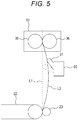
- Fig. 5 is a diagram showing a configuration example of the loop detection sensor 60.
- the recording medium 9 passes a path L1 shown by a broken line in Fig. 5 .
- the recording medium 9 passes a path L2 shown by a solid line in Fig. 5 .
- the loop detection sensor 60 can detect a size of the loop.
- the loop of the recording medium 9 is formed in one direction in which the loop detection sensor 60 is disposed.
- the loop detection sensor 60 includes an actuator 61 that displaces by coming into contact with a loop of a recording medium 9 as the loop is formed.
- the loop detection sensor 60 is formed so as to detect a size of a loop of a recording medium 9 according to a position of the actuator 61.
- FIG. 6 is a block diagram showing a configuration example of the control mechanism of the image formation apparatus 1.
- the image formation apparatus 1 is formed such that the controller 8 controls operation of the image formation unit 2 described above.
- the controller 8 includes a central processing unit (CPU) 70 and a memory 71, and causes the image formation unit 2 to operate by the CPU 70 reading and executing a program 78 stored in the memory 71.
- the operation panel 7 and a communication unit 72 are connected to the controller 8.
- the operation panel 7 includes a display unit 7a and an operation unit 7b.
- the display unit 7a includes, for example, a color liquid crystal display, and displays various operation screens that can be operated by the user.
- the operation unit 7b includes a touch panel key, or the like, and receives operation by the user.
- the controller 8 can acquire information input by the user via the operation panel 7, and can also control the image formation unit 2 on the basis of the information input by the user.
- the communication unit 72 communicates with an external apparatus via a network such as a local area network (LAN).
- a network such as a local area network (LAN).
- the controller 8 can acquire image data to be printed from an external apparatus via the communication unit 72.
- the controller 8 can also acquire information for controlling the image formation unit 2.
- the image formation unit 2 includes a delivery roller drive unit 73, a fixing roller drive unit 74, a fixing roller pressure contact force adjustment unit 75, and a heater 76.
- the delivery roller drive unit 73 includes, for example, a motor, or the like that rotationally drives each of the rollers for delivering a recording medium 9 along the delivery path 33.
- the delivery roller drive unit 73 drives a plurality of rollers including the pickup rollers 31a and 31b, the paper feed rollers 32a and 32b, the resist roller 34, the secondary transfer roller 23, and the ejection roller 37.
- drive force of the delivery roller drive unit 73 is formed so as to be transmitted to each of the rollers via an electromagnetic clutch.
- the delivery roller drive unit 73 sets system velocity designated by the controller 8 to drive each of the rollers.
- the system velocity is delivery velocity when a recording medium 9 is delivered along the delivery path 33.
- the delivery roller drive unit 73 can change velocity of delivering a recording medium 9 according to system velocity if the controller 8 gives an instruction to change the system velocity after the delivery roller drive unit 73 starts delivery of the recording medium 9.
- the delivery roller drive unit 73 can change the system velocity according to thickness of the recording medium 9 detected by the controller 8.
- the fixing roller drive unit 74 is a drive unit such as a motor that rotationally drives the fixing rollers 35 and 36. That is, the fixing rollers 35 and 36 are rotationally driven by a drive source different from each of the rollers for delivering a recording medium 9 along the delivery path 33. Therefore, velocity of delivering a recording medium 9 by the fixing rollers 35 and 36 can be set to the same velocity as velocity of delivering the recording medium 9 by each of the rollers, or to velocity different from the velocity of delivering the recording medium 9 by each of the rollers.
- the fixing roller pressure contact force adjustment unit 75 adjusts pressure contact force of the fixing roller 36 on the fixing roller 35 in the fixing unit 12. For example, the fixing roller pressure contact force adjustment unit 75 presses and energizes the fixing roller 36 toward the fixing roller 35, and adjusts the pressure contact force by adjusting the press force.
- the heater 76 is a heat source for heating the fixing roller 35 of the fixing unit 12.
- the heater 76 is driven by the controller 8 and is formed to heat the fixing roller 35 to maintain a predetermined fixing temperature.
- the fixing temperature differs depending on a type of a recording medium 9.
- the controller 8 is formed to control each of the delivery roller drive unit 73, the fixing roller drive unit 74, the fixing roller pressure contact force adjustment unit 75, and the heater 76 on the basis of a detection result from each of the envelope detection sensor 40, the basis weight detection sensor 50, and the loop detection sensor 60, which are included in the image formation unit 2. Although not shown in Fig. 6 , the controller 8 controls operation of the above-described image forming unit 10, needless to say. A detailed configuration and operation of the controller 8 will be described below.
- the CPU 70 of the controller 8 functions as an envelope judgment unit 81, a basis weight acquisition unit 82, a determination unit 83, and a print control unit 84 by executing the program 78.
- the print control unit 84 drives the image formation unit 2 to control image forming operation on a recording medium 9.
- the print control unit 84 drives the image formation unit 2 to start printing operation for forming an image on a recording medium 9 in a case where an instruction on execution of a print job is given via the communication unit 72, or in a case where an instruction on execution of a print job is given via the operation panel 7.
- the print control unit 84 drives the delivery roller drive unit 73, feeds a recording medium 9 from a tray among the paper feed tray 3 and the manual feed tray 4, whichever is designated by the user, and delivers the recording medium 9 along the delivery path 33.
- the print control unit 84 starts the delivery of the recording medium 9 by setting system velocity corresponding to plain paper on assumption that the recording medium 9 is plain paper, for example. Further, the print control unit 84 starts operation of generating a toner image in the image forming unit 10 with the start of delivering the recording medium 9. Thereafter, on the basis of a determination result from the determination unit 83, the print control unit 84 can appropriately change control for when forming an image on the recording medium 9.
- the envelope judgment unit 81 is a processing unit that judges whether or not a recording medium 9 delivered along the delivery path 33 is an envelope.
- the envelope judgment unit 81 drives the envelope detection sensor 40, and causes the envelope detection sensor 40 to detect whether or not the recording medium 9 is an envelope 15 when the recording medium 9 passes a position of the envelope detection sensor 40. Then, the envelope judgment unit 81 acquires a detection result output from the envelope detection sensor 40 and judges whether or not the recording medium 9 is an envelope on the basis of the detection result.
- the basis weight acquisition unit 82 is a processing unit that acquires a basis weight of a recording medium 9 delivered along the delivery path 33.
- the basis weight acquisition unit 82 drives the basis weight detection sensor 50, and causes the basis weight detection sensor 50 to detect a basis weight of the recording medium 9 when the recording medium 9 passes a position of the basis weight detection sensor 50. Then, the basis weight acquisition unit 82 acquires a basis weight detection result output from the basis weight detection sensor 50. For example, in a case where the envelope judgment unit 81 judges that the recording medium 9 is an envelope 15, the basis weight acquisition unit 82 acquires a basis weight of the envelope 15 detected by the basis weight detection sensor 50. Further, in a case where the envelope judgment unit 81 judges that the recording medium 9 is not an envelope 15 but one piece of sheet, the basis weight acquisition unit 82 acquires a basis weight of the one piece of sheet detected by the basis weight detection sensor 50.
- a basis weight that the basis weight detection sensor 50 detects at a portion where two sheets overlap and a basis weight that the basis weight detection sensor 50 detects at a flap where two sheets do not overlap are different. This is because an amount of transmitted light of light emitted from the second light source 52 may be lowered at the portion where the two sheets overlap than at a flap, tint of the portion where the two sheets overlap may be slightly different from tint of the flap, and an amount of reflected light of light emitted from the first light source 51 may vary. Therefore, the basis weight acquisition unit 82 drives the basis weight detection sensor 50 so as to detect basis weight at either the portion where the two sheets overlap or the flap.
- Figs. 7A to 7D are diagrams describing operation of the envelope detection sensor 40 and the basis weight detection sensor 50.
- the envelope detection sensor 40 On the delivery path 33 through which a recording medium 9 is delivered, the envelope detection sensor 40 is disposed upstream of the basis weight detection sensor 50. Therefore, as shown in Fig. 7A , a recording medium 9 delivered in a direction of an arrow F2 along the delivery path 33 first passes the position of the envelope detection sensor 40, and then passes the position of the basis weight detection sensor 50.
- Velocity of delivering of the recording medium 9 is known, and a distance between the envelope detection sensor 40 and the basis weight detection sensor 50 is also known. Therefore, it is possible to predict a timing when the same portion as the portion detected by the envelope detection sensor 40 passes the position of the basis weight detection sensor 50.
- the basis weight acquisition unit 82 can cause the basis weight detection sensor 50 to detect a basis weight of the portion 17 where two sheets of the envelope 15 overlap as shown in Fig. 7C by causing the basis weight detection sensor 50 to detect the basis weight after a predetermined time from a time when the envelope detection sensor 40 detects the portion 17 where two sheets of the envelope 15 overlap.
- a flap 18 of the envelope 15 passes the position of the basis weight detection sensor 50 after a predetermined time from a time when the envelope detection sensor 40 detects the flap 18. Therefore, the basis weight acquisition unit 82 can cause the basis weight detection sensor 50 to detect a basis weight of the flap 18 of the envelope 15 as shown in Fig. 7D by causing the basis weight detection sensor 50 to detect the basis weight after a predetermined time from a time when the envelope detection sensor 40 detects the flap 18 of the envelope 15.
- the basis weight detection sensor 50 can detect a basis weight of a flap 18 of an envelope 15 in a similar manner to a case where a recording medium 9 is one piece of sheet. However, in a case where the basis weight detection sensor 50 detects a basis weight of a portion 17 where two sheets of the envelope 15 overlap, an amount of transmitted light of light emitted from the second light source 52 may be lowered, and an amount of reflected light of light emitted from the first light source 51 may vary. Therefore, in this case, the basis weight may not be able to be detected properly.
- the basis weight acquisition unit 82 cause the basis weight detection sensor 50 to detect a basis weight of a portion 17 where two sheets of the envelope 15 overlap by using a method different from a basis weight detection method used in a case where a recording medium 9 is one piece of sheet. That is, the basis weight acquisition unit 82 sets a basis weight detection method by the basis weight detection sensor 50 to a first method in a case where the envelope judgment unit 81 judges the recording medium 9 not to be an envelope 15, and to a second method in a case where the envelope judgment unit 81 judges the recording medium 9 to be an envelope 15, the second method being different from the first method.
- the basis weight acquisition unit 82 uses the second method to detect the basis weight.
- an amount of light or sensitivity of the light transmissive sensor or light reflective sensor in the basis weight detection sensor 50 is increased as compared to the first method used in a case where the recording medium 9 is not an envelope 15.
- Figs. 8A and 8B are diagrams exemplifying a plurality of types of envelopes 15 delivered in a delivery direction F2. For example, as shown in Fig. 8A , in a case where a flap 18 of an envelope 15 is on a rear end side of the delivery direction F2, the flap 18 passes a position detected by the basis weight detection sensor 50.
- the basis weight detection sensor 50 can detect a basis weight of a flap 18 of the envelope 15. Similarly, in a case where a flap 18 of an envelope 15 is on a head end side of the delivery direction F2, the flap 18 passes a position detected by the basis weight detection sensor 50. Therefore, the basis weight detection sensor 50 can detect a basis weight of the flap 18 of the envelope 15.
- the flap 18 does not necessarily pass a position detected by the basis weight detection sensor 50. Therefore, in a case where an envelope 15 is delivered in an orientation shown in Fig. 8B , there may be a case where the basis weight detection sensor 50 cannot detect a basis weight of a flap 18 of the envelope 15. In such a case, it is preferable that the basis weight acquisition unit 82 cause the basis weight detection sensor 50 to detect a basis weight of a portion 17 where two sheets of the envelope 15 overlap, because the envelope detection sensor 40 also cannot detect the flap 18 of the envelope 15.
- the determination unit 83 is a processing unit that determines control for when an image is formed on a recording medium 9 on the basis of a judgment result from the envelope judgment unit 81 and a basis weight acquired by the basis weight acquisition unit 82.
- the determination unit 83 reads reference information 79 stored in advance in the memory 71, and determines the control on the basis of reference information 79.
- Fig. 9 is a diagram showing an example of the reference information 79.
- the reference information 79 is information in which system velocity Vs, fixing roller velocity Vt, whether or not loop control is performed, fixing temperature T, and fixing roller pressure contact force FP are defined in advance for each type of the recording media 9.
- the reference information 79 defines first velocity VI as system velocity Vs.
- the first velocity VI is, for example, 200 mm/s.
- the fixing roller velocity Vt should be set to equal to the system velocity Vs
- the loop control should be set to "performed”
- the fixing temperature T should be set to first temperature T1
- the fixing roller pressure contact force FP should be set to first pressure contact force FP1.
- the loop control is a control by which a recording medium 9 is supplied to the fixing unit 12 with a loop of the recording medium 9 formed upstream of the fixing unit 12.
- the first temperature T1 is, for example, 170°C.
- the first pressure contact force FP1 is a standard pressure contact force (normal pressure contact force) for when an image is formed on a recording medium 9 in the image formation apparatus 1.
- the reference information 79 defines first velocity VI as system velocity Vs, as in a case of plain paper.
- the fixing roller velocity Vt should be set to equal to the system velocity Vs
- the loop control should be set to "performed”
- the fixing temperature T should be set to second temperature T2
- the fixing roller pressure contact force FP should be set to second pressure contact force FP2.
- the second temperature T2 is, for example, 150°C.
- the second pressure contact force FP2 is pressure contact force smaller than pressure contact force of the first pressure contact force FP1. That is, because thin paper is thinner than plain paper, the fixing temperature T can be lowered and pressure contact force FP of the fixing roller 36 can be reduced.
- the reference information 79 defines second velocity V2 as system velocity Vs, the second velocity V2 being lower than the first velocity VI.
- the fixing roller velocity Vt should be set to equal to the system velocity Vs
- the loop control should be set to "performed”
- the fixing temperature T should be set to second temperature T2
- the fixing roller pressure contact force FP should be set to third pressure contact force FP3.
- the second velocity V2 is, for example, 100 mm/s.
- the third pressure contact force FP3 is pressure contact force greater than pressure contact force of the first pressure contact force FP1. That is, for thick paper, system velocity Vs is lowered so that an image is properly transferred onto a sheet. Therefore, fixing temperature T can be lowered as in a case of thin paper. However, in order to properly fix an image onto thick paper, it is preferable that pressure contact force FP of the fixing roller 36 be greater than the normal pressure contact force.
- the reference information 79 defines first velocity VI as system velocity Vs.
- the fixing roller velocity Vt should be set to about a few percent faster than the system velocity Vs
- the loop control should be set to "not performed”
- the fixing temperature T should be set to lower than the first temperature T1
- the fixing roller pressure contact force FP should be set to smaller than the first pressure contact force FP1.
- a thin envelope is susceptible to wrinkling when passing the fixing unit 12 if a loop is formed upstream of the fixing unit 12. Especially when the thin envelope is skewed, wrinkling is noticeable. This phenomenon occurs when a bent generated in a portion 17 where two sheets of the envelope 15 overlap is fixed as is in the fixing unit 12. Therefore, it is defined that, for a thin envelope, velocity (fixing roller velocity Vt) of delivery by the fixing rollers 35 and 36 should be set to velocity slightly faster than system velocity Vs so that a loop is not formed upstream of the fixing unit 12. However, if the fixing rollers 35 and 36 pull the thin envelope too much, an image secondarily transferred onto the thin envelope by the secondary transfer roller 23 may be disturbed. Therefore, difference in velocity between the fixing roller velocity Vt and the system velocity Vs is preferably kept within a few percent. If the loop is not formed upstream of the fixing unit 12, the fixing roller velocity Vt may be set to velocity equal to the system velocity Vs.
- the fixing temperature T is higher than fixing temperature of the thin paper.
- the fixing roller pressure contact force FP may be pressure contact force similar to a case of thin paper.
- the reference information 79 defines second velocity V2 as system velocity Vs.
- the fixing roller velocity Vt should be set to equal to the system velocity Vs
- the loop control should be set to "performed”
- the fixing temperature T should be set to lower than the first temperature T1
- the fixing roller pressure contact force FP should be set to normal pressure contact force that is the same as the first pressure contact force FP1.
- fixing temperature T can be lowered as in a case of a thin envelope.
- fixing temperature T for a thick envelope may be lower than fixing temperature T for a thin envelope.
- pressure contact force FP of the fixing roller 36 be greater than pressure contact force FP for a thin envelope. Therefore, for a thick envelope, it is defined that pressure contact force FP of the fixing roller 36 should be set to the same as normal pressure contact force.
- reference information 79 may be used, the reference information 79 defining specific control for three or more types of envelopes according to thickness of the envelope 15.
- the determination unit 83 determines control for when an image is formed on a recording medium 9 on the basis of the reference information 79 as described above. For example, when the envelope judgment unit 81 judges that the recording medium 9 is an envelope 15, the determination unit 83 identifies thickness of the envelope 15 on the basis of a basis weight of the envelope 15 acquired by the basis weight acquisition unit 82, and judges whether the envelope 15 is a thin envelope or a thick envelope. In a case where the envelope 15 is a thin envelope as a result, the determination unit 83 refers to a field of thin envelope in the reference information 79, and determines system velocity Vs, fixing roller velocity Vt, loop control "not performed", fixing temperature T, and fixing roller pressure contact force FP, which are suitable for the thin envelope.
- the determination unit 83 refers to a field of thick envelope in the reference information 79, and determines system velocity Vs, fixing roller velocity Vt, loop control "performed", fixing temperature T, and fixing roller pressure contact force FP, which are suitable for the thick envelope. Then, the determination unit 83 outputs the determination result to the print control unit 84.
- the determination unit 83 determines control corresponding to a type of sheet on the basis of the reference information 79, and notifies the print control unit 84 of the determined control.
- Determination by the determination unit 83 is made, at latest, before a tip of the recording medium 9 is sent downstream of the resist roller 34. That is, the determination unit 83 determines the control while delivery of the recording medium 9 by the resist roller 34 is temporarily stopped before or after the tip of the recording medium 9 reaches the resist roller 34.
- the print control unit 84 After starting delivery of the recording medium 9, the print control unit 84 temporarily stops the delivery of the recording medium 9 at a timing when the tip of the recording medium 9 reaches the resist roller 34. Thereafter, the print control unit 84 drives the resist roller 34 again and sends the tip of the recording medium 9 toward the secondary transfer roller 23 at a timing when an image primarily transferred onto the intermediate transfer belt 22 by the image forming unit 10 reaches the position of the secondary transfer roller 23. At this time, the print control unit 84 performs control that reflects the determination result from the determination unit 83. For example, in a case where the determination unit 83 has determined that system velocity Vs is to be reduced, the print control unit 84 reduces the system velocity Vs when the resist roller 34 is driven again, and reduces velocity of delivering the recording medium 9.
- the print control unit 84 sets the velocity of delivering the recording medium 9 by the fixing rollers 35 and 36 to a fixing roller velocity Vt determined by the determination unit 83, and rotationally drives the fixing rollers 35 and 36.
- the print control unit 84 performs control to form or not to form a loop of the recording medium 9 upstream of the fixing unit 12 on the basis of whether or not loop control is performed determined by the determination unit 83. For example, for a thin envelope, the loop control is determined to be "not performed”. Therefore, the print control unit 84 adjusts system velocity Vs and fixing roller velocity Vt so that the loop detection sensor 60 does not detect a loop of the recording medium 9.
- the print control unit 84 By driving the heater 76, the print control unit 84 sets fixing temperature T in the fixing unit 12 to a temperature determined by the determination unit 83. By driving the fixing roller pressure contact force adjustment unit 75, the print control unit 84 adjusts pressure contact force of the fixing roller 36 to a value determined by the determination unit 83.
- the print control unit 84 can switch control for when an image is formed on the envelope 15 according to thickness of the envelope 15. In other words, the print control unit 84 selects an optimum control parameter corresponding to the thickness of the envelope 15 and performs control so that the image is formed on the envelope 15.
- image formation suitable for a thick envelope is performed by a first control parameter suitable for a thick envelope being applied.
- image formation suitable for a thin envelope is performed by a second control parameter suitable for a thin envelope being applied, the second control parameter being a control parameter different from a control parameter for a thick envelope.
- the conventional image formation apparatus 1 can reduce wrinkling of an envelope 15, and therefore deterioration of quality of a printed material can be reduced.
- Fig. 10 is a flowchart showing an example of a processing procedure performed by the controller 8.
- the processing is performed by the CPU 70 executing the program 78.
- the processing is processing started in a case where the user gives an instruction on execution of a print job.
- the controller 8 starts a print job (step S1). Accordingly, the controller 8 sets the system velocity Vs to the first velocity VI (step S2). That is, the controller 8 sets the system velocity Vs to the first velocity VI on assumption that the recording medium 9 is plain paper, because whether or not the recording medium 9 is the envelope 15 is unknown at this point. Then, the controller 8 starts operation of supplying and delivering the recording medium 9 to the delivery path 33 from either the paper feed tray 3 or the manual feed tray 4 by driving the delivery roller drive unit 73 (step S3).
- the controller 8 judges whether or not the envelope detection sensor 40 has detected the recording medium 9 (step S4). If the envelope detection sensor 40 detects the recording medium 9 (YES in step S4), the controller 8 judges whether or not the recording medium 9 is the envelope 15 on the basis of detection result of the envelope detection sensor 40 (step S5).
- the controller 8 sets the second method as a method for detection by the basis weight detection sensor 50 (step S6).
- the controller 8 specifies a setting so that basis weight can be detected at a portion 17 where two sheets of the envelope 15 overlap by increasing an amount of light of the first light source 51 and second light source 52 to higher than a normal amount of light (amount of light when detecting basis weight of one piece of sheet), or by increasing sensitivity of the light receiving element 53 to higher than a normal sensitivity (sensitivity when detecting basis weight of one piece of sheet).
- the controller 8 drives the basis weight detection sensor 50 to acquire basis weight of the envelope 15 from the basis weight detection sensor 50 (step S7).
- the controller 8 executes envelope control determination processing (step S8).
- Fig. 11 is a flowchart showing an example of a detailed processing procedure of the envelope control determination processing (step S8).
- the controller 8 judges whether or not the basis weight of the envelope 15 detected by the basis weight detection sensor 50 is equal to or more than a predetermined value (step S20). As a result, if the basis weight of the envelope 15 is equal to or greater than the predetermined value (YES in step S20), the controller 8 decides that the envelope is a thick envelope (step S21). If deciding that the envelope is a thick envelope, the controller 8 changes a setting of the system velocity Vs on the basis of the reference information 79 (step S22). In addition, the controller 8 changes a setting of fixing roller velocity Vt (step S23) and changes a setting of fixing temperature T on the basis of the reference information 79 (step S24).
- the controller 8 decides that the envelope is a thin envelope (step S25). If deciding that the envelope is a thin envelope, the controller 8 changes a setting of the fixing roller velocity Vt on the basis of the reference information 79 (step S26). That is, in a case where the basis weight of the envelope 15 is less than a predetermined value, the controller 8 sets velocity of delivering the envelope 15 by the fixing rollers 35 and 36 to higher than normal delivery velocity (first velocity v1). In addition, the controller 8 changes a setting so as not to perform loop control (step S27). Further, the controller 8 changes a setting of the fixing temperature T on the basis of the reference information 79 (step S28).
- the controller 8 changes a setting of the fixing temperature T of the fixing roller 35 to a temperature lower than a normal fixing temperature (first temperature T1).
- the controller 8 changes a setting of pressure contact force of the fixing roller 36 (step S29). That is, in a case where the basis weight of the envelope 15 is less than a predetermined value, the controller 8 changes a setting of pressure contact force FP of the fixing roller 36 to a force weaker than a normal pressure contact force (first pressure contact force FP1). This completes the envelope control determination processing.
- the controller 8 switches a control of subsequent image forming operation to a control determined in the envelope control determination processing (step S8) (step S9). Then, the controller 8 applies the switched control to control the subsequent image forming operation. As a result, if the recording medium 9 is the envelope 15, control corresponding to the thickness of the envelope 15 is performed, by which deterioration of quality of a printed material can be reduced.
- the controller 8 sets the first method as a method for detection by the basis weight detection sensor 50 (step S10). For example, by setting an amount of light of the first light source 51 and second light source 52 to a normal amount of light, and setting sensitivity of the light receiving element 53 to normal sensitivity, the controller 8 specifies a setting so that a basis weight of one piece of sheet can be properly detected. Thereafter, the controller 8 drives the basis weight detection sensor 50 to acquire basis weight of the sheet from the basis weight detection sensor 50 (step S11). After being able to acquire basis weight of the envelope 15, the controller 8 executes sheet control determination processing (step S12).
- the sheet control determination processing is processing for determining control when image is formed on the sheet on the basis of the reference information 79.
- the controller 8 judges whether or not it is necessary to switch control of the image forming operation (step S13).
- plain paper is set as a default. Therefore, when the sheet is thin paper or thick paper other than plain paper, it is necessary to switch the control.
- the controller 8 switches a control of subsequent image forming operation to a control determined in the sheet control determination processing (step S12) (step S14). Then, the controller 8 applies the switched control to control the subsequent image forming operation.
- the image formation apparatus 1 performs image forming suitable for thin paper or thick paper.
- the controller 8 controls the subsequent image forming operation without switching the control of the image forming operation.
- the image formation apparatus 1 performs image forming suitable for plain paper.
- controller 8 waits until the print job ends (step S15). Then, when the print job ends (YES in step S15), all the processing by the controller 8 ends.
- the image formation apparatus 1 includes the image formation unit 2 that forms an image on a recording medium 9 delivered along a predetermined delivery path 33 and outputs the recording medium 9, the envelope judgment unit 81 that judges whether or not the recording medium 9 is an envelope 15, the basis weight acquisition unit 82 that acquires a basis weight of the recording medium 9, the determination unit 83 that determines control for when an image is formed on the recording medium 9 on the basis of a judgment result from the envelope judgment unit 81 and a basis weight acquired by the basis weight acquisition unit 82, and the print control unit 84 that controls operation of the image formation unit 2 on the basis of a determination result from the determination unit 83.
- the image formation apparatus 1 can form an image with optimum operation according to a basis weight of the envelope 15. Specifically, when forming an image on a thick envelope, image formation with optimum operation according to the thick envelope can be performed, meanwhile when forming an image on a thin envelope, image formation with optimum operation corresponding to the thin envelope can be performed. Thus, it is possible to output a high-quality printed material while reducing wrinkling of a thin envelope.
- the present embodiment exemplifies the case where the basis weight acquisition unit 82 causes the basis weight detection sensor 50 to detect a basis weight in both cases where a recording medium 9 is judged to be an envelope 15 and where the recording medium 9 is judged not to be an envelope 15.
- a configuration may be employed in which the basis weight acquisition unit 82 causes the basis weight detection sensor 50 to detect a basis weight of an envelope 15 exclusively in a case where a recording medium 9 is judged to be an envelope 15.
- the flowchart shown in Fig. 10 exemplifies a case where a basis weight detection method by the basis weight detection sensor 50 is set to the first method in a case where the recording medium 9 is judged not to be an envelope 15, and to the second method in a case where the recording medium 9 is judged to be an envelope 15, the second method being different from the first method.
- this is processing on a premise that a basis weight is detected at a portion 17 where two sheets of the envelope 15 overlap.
- the basis weight detection sensor 50 is caused to detect a basis weight at a flap 18 of an envelope 15 in a case where the recording medium 9 is judged to be the envelope 15, a method for detecting a basis weight by the basis weight detection sensor 50 is not necessary to be set to the second method, and it is only required to detect the basis weight by adopting the first method as in a case where the recording medium 9 is a sheet. Therefore, time required to switch a method for detection by the basis weight detection sensor 50 can be saved, and therefore efficient processing can be achieved.
- the present embodiment exemplifies a case where the determination unit 83 determines a plurality of control parameters including velocity of delivery by the fixing rollers 35 and 36 that fix an image onto a recording medium 9, whether or not a loop of the recording medium 9 is formed between a position where an image is transferred onto the recording medium 9 and the fixing rollers 35 and 36, fixing temperature by the fixing roller 35, and pressure contact force by the fixing roller 36, on the basis of a judgment result from the envelope judgment unit 81 and a basis weight acquired by the basis weight acquisition unit 82.
- the determination unit 83 is only required to determine at least one of the above-described plurality of control parameters.
- the present embodiment exemplifies a case where the basis weight detection sensor 50 includes a light transmissive sensor and a light reflective sensor.
- the basis weight detection sensor 50 is not necessarily limited to a basis weight detection sensor including both the light transmitting type sensor and the light reflective sensor, and may include either the light transmissive sensor alone or the light reflective sensor alone.
- the above-described first embodiment exemplifies a case where the envelope judgment unit 81 judges whether or not a recording medium 9 is an envelope 15 on the basis of a detection result from the envelope detection sensor 40, and the basis weight acquisition unit 82 acquires a basis weight detected by the basis weight detection sensor 50.
- the present embodiment there will be described an aspect in which a user inputs information about a type of a recording medium 9 or a basis weight of the recording medium 9 to an operation panel 7.
- a configuration of an image formation apparatus 1 according to the present embodiment is similar to the configuration of the image formation apparatus 1 described in the first embodiment.
- an envelope judgment unit 81 and a basis weight acquisition unit 82 function in a controller 8 before the image formation apparatus 1 starts a print job. That is, each of the envelope judgment unit 81 and basis weight acquisition unit 82 functions while the user operates the operation panel 7 to perform a setting operation related to the print job. Then, on the operation panel 7, the controller 8 displays an operation screen on which the user can input a type of a recording medium 9 or a basis weight of the recording medium 9.
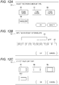
- Figs. 12A to 12C are diagrams showing operation screens displayed in a display unit 7a of the operation panel 7.
- Fig. 12A shows a screen G1 for selecting a type of a recording medium 9.
- the envelope judgment unit 81 displays the screen G1 shown in Fig. 12A in the display unit 7a of the operation panel 7, and receives operation by the user.
- a plurality of buttons B1, B2, B3, and B4 corresponding to a type of a recording medium 9 is displayed.
- the user selects one button from among the plurality of buttons B1 to B4 for operation when the screen G1 is displayed.
- the user can designate a type of the recording medium 9 with respect to the image formation apparatus 1.
- Figure 12A exemplifies a case where the button B4 for envelope is selected by the user.
- the envelope judgment unit 81 receives selection operation by the user with respect to the screen G1 as described above. Then, in a case where the user selects the button B4 for envelope on the screen G1, the envelope judgment unit 81 judges that the recording medium 9 is an envelope. Therefore, in the present embodiment, it is possible to identify whether or not a recording medium 9 is an envelope before a print job is started in the image formation apparatus 1.
- Figure 12B shows a screen G2 that is displayed when the user selects an envelope.
- the screen G2 is a screen for inputting a basis weight of an envelope.
- the screen G2 is provided with a basis weight display field R1 for displaying a basis weight of the envelope, and a button group B5 for a user to input a numerical value is displayed at a position below the basis weight display field R1.
- the user can manually input a basis weight of the envelope used for image formation by operating the screen G2.
- the basis weight acquisition unit 82 receives operation by the user with respect to the screen G2 as described above. Then, the basis weight acquisition unit 82 acquires the basis weight input to the screen G2 by the user as the basis weight of the envelope used for image formation. Therefore, in the present embodiment, it is also possible to acquire a basis weight of an envelope before a print job is started in the image formation apparatus 1.
- the controller 8 may display a screen G3 as shown in Fig. 12C on the display unit 7a instead of the screen G2 in Fig. 12B .
- the screen G3 shown in Fig. 12C is a screen for displaying in a list format of a plurality of types of envelope images (thumbnail images) B7, B8, B9, and B10 registered in advance in the image formation apparatus 1
- Each of the envelope images B7 to B10 includes a function as a button with which the user can perform selection operation.
- a memory 71 of the controller 8 stores envelope information including envelope images and corresponding envelope basis weights, the envelope information being registered in the image formation apparatus 1 in advance. Then, when the user selects one envelope image, the basis weight corresponding to the envelope image can be acquired. That is, the basis weight acquisition unit 82 acquires a basis weight of an envelope used for image formation by receiving operation on the screen G3 by the user and referring to envelope information on the basis of the envelope image selected by the user. In this case as well, it is possible to acquire a basis weight of an envelope before a print job is started in the image formation apparatus 1.
- the image formation apparatus 1 can judge whether or not a recording medium 9 is an envelope on the basis of information input by a user before starting a print job, and, if the recording medium 9 is an envelope, can acquire a basis weight of the envelope. Therefore, with the image formation apparatus 1, various control parameters corresponding to basis weights of envelopes can be set by default for a print job executed on the basis of an instruction from the user. Therefore, it is not necessary to change system velocity Vs, or the like, after starting delivery operation of an envelope as a recording medium 9.
- the image formation apparatus 1 can perform image formation corresponding to a basis weight of the envelope as in the first embodiment. Therefore, even if the recording medium 9 is a thin envelope, it is possible to perform image formation while reducing wrinkling of the envelope.
- the image formation apparatus 1 may have a configuration in which an envelope detection sensor 40 and a basis weight detection sensor 50 are disposed along a delivery path 33 for a recording medium 9. Therefore, in a case where the user does not designate a type of a recording medium 9 or does not designate a basis weight of an envelope before executing a print job, the image formation apparatus 1 performs operation described in the first embodiment. Thus, even if the recording medium 9 is an envelope, the image formation apparatus 1 can perform appropriate image forming operation corresponding to a basis weight of the envelope.
- the image formation apparatus 1 may not include an envelope detection sensor 40 and a basis weight detection sensor 50.
- an image formation apparatus 1 acquires information about a recording medium 9 and a basis weight thereof from an external apparatus.
- a configuration of an image formation apparatus 1 according to the present embodiment is similar to the configuration of the image formation apparatus 1 described in the first embodiment.
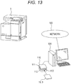
- Fig. 13 is a diagram showing a configuration example of the image formation apparatus 1 according to the third embodiment.
- the image formation apparatus 1 is connected to an external information processing apparatus 101 via a network 100 such as a LAN.
- the information processing apparatus 101 includes, for example, a personal computer (PC) or the like, and can communicate with the image formation apparatus 1 via the network 100.
- an image formation system is constructed by the image formation apparatus 1 and the information processing apparatus 101.
- the image formation system may include an apparatus other than the image formation apparatus 1 and the information processing apparatus 101.
- the information processing apparatus 101 includes a recording medium measurement apparatus 110.
- the recording medium measurement apparatus 110 has a substantially U-shaped outer shape in which an upper housing 111 and a lower housing 112 are disposed so as to face each other at a predetermined distance in a vertical direction.
- a gap between the upper housing 111 and the lower housing 112 is an insertion space 113 into which a recording medium 9 can be inserted.
- the upper housing 111 and the lower housing 112 have configurations similar to the configurations of the envelope detection sensor 40 and the basis weight detection sensor 50 described in the first embodiment. That is, there is described in the first embodiment an example in which the envelope detection sensor 40 and the basis weight detection sensor 50 are disposed so as to sandwich a delivery path 33 for a recording medium 9.
- each of an envelope detection sensor 40 and a basis weight detection sensor 50 is disposed so as to sandwich the insertion space 113. Therefore, by causing the envelope detection sensor 40 and the basis weight detection sensor 50 to operate with a recording medium 9 inserted in the insertion space 113, the recording medium measurement apparatus 110 can detect whether or not the recording medium 9 is an envelope, and also can detect a basis weight of the recording medium 9.
- the recording medium measurement apparatus 110 starts operation to detect whether or not the recording medium 9 inserted in the insertion space 113 is an envelope and detect a basis weight of the recording medium 9.
- the recording medium measurement apparatus 110 outputs, to the information processing apparatus 101, a detection result of whether or not the recording medium 9 is an envelope and the basis weight of the recording medium 9.
- the information processing apparatus 101 When the information processing apparatus 101 receives the detection result of whether or not the recording medium 9 is an envelope and the basis weight of the recording medium 9 from the recording medium measurement apparatus 110, the information processing apparatus 101 generates information about the recording medium 9 on the basis of the information. At this time, if it is detected that the recording medium 9 is an envelope, the information processing apparatus 101 converts the basis weight of the recording medium 9 into a basis weight of an envelope. Then, the information processing apparatus 101 transmits information about the recording medium 9 to the image formation apparatus 1.
- the image formation apparatus 1 When receiving the information about the recording medium 9 via a communication unit 72, the image formation apparatus 1 saves the information in the memory 71 as information about the recording medium 9 newly set in a paper feed tray 3 or a manual feed tray 4. Therefore, the image formation apparatus 1 can register the information about the recording medium 9 before starting a print job.
- the recording medium measurement apparatus 110 may not have an envelope detection sensor 40 built in.
- the information processing apparatus 101 can grasp that a recording medium 9 is an envelope by receiving envelope designation operation by the user, and can convert a basis weight of the recording medium 9 into a basis weight of the envelope.
- an envelope judgment unit 81 can judge whether or not the recording medium 9 is an envelope on the basis of information about the recording medium 9, the information being received from outside via the communication unit 72.
- the basis weight acquisition unit 82 can acquire a basis weight of the recording medium 9 on the basis of the information about the recording medium 9, the information being received from outside via the communication unit 72. Therefore, in a case where a recording medium 9 is an envelope, the image formation apparatus 1 can perform image formation corresponding to a basis weight of the envelope as in the second embodiment. Therefore, even if the recording medium 9 is a thin envelope, it is possible to perform image formation while reducing wrinkling of the envelope.
- the above description exemplifies the aspect in which the recording medium measurement apparatus 110 transmits information about a recording medium 9 to the image formation apparatus 1 via the information processing apparatus 101.
- a configuration may be employed in which the recording medium measurement apparatus 110 directly transmits information about a recording medium 9 to the image formation apparatus 1 without using an information processing apparatus 101.
- the image formation apparatus 1 may have a configuration in which an envelope detection sensor 40 and a basis weight detection sensor 50 are disposed along a delivery path 33 for a recording medium 9. Therefore, in a case where information about a recording medium 9 is not saved in the memory 71 before a print job, the image formation apparatus 1 performs operation described in the first embodiment. Thus, even if the recording medium 9 is an envelope, the image formation apparatus 1 can perform appropriate image forming operation corresponding to a basis weight of the envelope.
- the image formation apparatus 1 may not include an envelope detection sensor 40 and a basis weight detection sensor 50.
- the above embodiments exemplify a case where an image formation apparatus 1 is formed as an MFP.
- the image formation apparatus 1 is not limited to an image formation apparatus formed as an MFP. That is, the image formation apparatus 1 may be a printer including a printing function exclusively.
- the above embodiments exemplify a case where a program 78 executed by a controller 8 of an image formation apparatus 1 is stored in a memory 71 in advance.
- the program 78 may be installed or updated in the image formation apparatus 1 by being downloading from outside via a communication unit 72.
- the program 78 is provided so as to be downloadable on the image formation apparatus 1 via a network.
- the program 78 may be provided recorded on a computer-readable recording medium such as a CD-ROM or a USB memory.
Landscapes
- Physics & Mathematics (AREA)
- General Physics & Mathematics (AREA)
- Engineering & Computer Science (AREA)
- Multimedia (AREA)
- Signal Processing (AREA)
- Microelectronics & Electronic Packaging (AREA)
- Fixing For Electrophotography (AREA)
- Control Or Security For Electrophotography (AREA)
Abstract
Description
- The present invention relates to an image formation apparatus and a control method therefor, and, in particular, to a technique for forming an image suitable for an envelope when the envelope is a recording medium subjected to image formation.
- Conventionally, there is known an image formation apparatus such as a printer or a multifunction peripheral (MFP) that measures thickness of a sheet of printing paper, or the like, and performs setting for the sheet on the basis of the measured thickness to form an image (For example,
Japanese Patent Application Laid-Open No. 2018-10056 Japanese Patent Application Laid-Open No. 2017-211634 - In recent years, there are increasing types of envelopes used for being subjected to image formation in an image formation apparatus, and there are envelopes of various thicknesses depending on the types of the envelopes. In a case of being used as a recording medium subjected to image formation by an image formation apparatus, an envelope has a problem of being susceptible to wrinkling when passing a fuser, as compared with a sheet such as ordinary printing paper. Therefore, an image formation apparatus is formed to reduce wrinkling on an envelope as a recording medium subjected to image formation by performing control different from control performed when a sheet is subjected to the image formation.
- However, in a case where a recording medium is an envelope, a conventional image formation apparatus uniformly applies a predetermined setting value for envelope to form an image. That is, the conventional image formation apparatus applies the same setting value to form an image both when a thin envelope is used and when a thick envelope is used.
- However, in general, a thin envelope is characterized by being more susceptible than a thick envelope to wrinkling when passing a fuser. Therefore, the conventional image formation apparatus has a problem that a thin envelope as a recording medium subjected to image formation may still be wrinkled, resulting in deterioration in quality of a printed material.
- The present invention has been made to solve the above-described problem, and an object of the present invention is to provide an image formation apparatus and a control method therefor that are capable of appropriately forming an image according to a type of an envelope.
- To achieve the abovementioned object, according to an aspect of the present invention, an image formation apparatus reflecting one aspect of the present invention comprises: an image formation means that forms an image on a recording medium delivered along a predetermined delivery path and outputs the recording medium; an envelope judgment means that judges whether or not the recording medium is an envelope; a basis weight acquisition means that acquires a basis weight of the recording medium; a determination means that determines control for when an image is formed on the recording medium on the basis of a judgment result from the envelope judgment means and a basis weight acquired by the basis weight acquisition means; and a control means that controls operation of the image formation means on the basis of a determination result from the determination means.
- The advantages and features provided by one or more embodiments of the invention will become more fully understood from the detailed description given hereinbelow and the appended drawings which are given by way of illustration only, and thus are not intended as a definition of the limits of the present invention:
-
Fig. 1 is a diagram showing an example of an external configuration of an image formation apparatus; -
Fig. 2 is a diagram showing an example of an internal structure of an image formation unit; -
Figs. 3A and 3B are diagrams showing a configuration example of an envelope detection sensor; -
Fig. 4 is a diagram showing a configuration example of a basis weight detection sensor; -
Fig. 5 is a diagram showing a configuration example of a loop detection sensor; -
Fig. 6 is a block diagram showing a configuration example of a control mechanism of the image formation apparatus; -
Figs. 7A to 7D are diagrams describing operation of the envelope detection sensor and the basis weight detection sensor; -
Figs. 8A and 8B are diagrams exemplifying an aspect of delivering an envelope; -
Fig. 9 is a diagram showing an example of reference information; -
Fig. 10 is a flowchart showing an example of a processing procedure performed by a controller; -
Fig. 11 is a flowchart showing an example of a detailed processing procedure of envelope control determination processing; -
Figs. 12A to 12C are diagrams showing operation screens displayed in an operation panel; and -
Fig. 13 is a diagram showing a configuration example of an image formation apparatus according to a third embodiment. - Hereinafter, one or more embodiments of the present invention will be described with reference to the drawings. However, the scope of the invention is not limited to the disclosed embodiments. In the embodiments described below, components common to each other are provided with the same reference signs, so that repeated description of these components is omitted.
-
Fig. 1 is a diagram showing animage formation apparatus 1 according to an embodiment of the present invention. Theimage formation apparatus 1 shown inFig. 1 is formed as a multifunction peripheral (MFP) including a plurality of functions such as a copy function, a scanning function, and a print function, for example. Focusing on the print function, theimage formation apparatus 1 is a type of apparatus that forms an image with an electrophotographic system, and is an apparatus capable of forming a color image by a tandem system. Theimage formation apparatus 1 includes animage formation unit 2 in a central portion of a main body of the apparatus. Apaper feed tray 3 provided below theimage formation unit 2 can accommodate recording medium such as a sheet or an envelope in advance. Theimage formation unit 2 includes an openable and closablemanual feed tray 4 on a side surface of the main body of the apparatus. Theimage formation apparatus 1 feeds a recording medium set in thepaper feed tray 3 or on themanual feed tray 4 one by one, forms an image on the recording medium, and ejects the recording medium to apaper ejection tray 5 provided above. - The
image formation apparatus 1 includes animage reading unit 6 in an upper part of the main body of the apparatus. Theimage reading unit 6 is for reading an image of a document in a case where, for example, the copy function or the scanning function is selected. That is, theimage reading unit 6 optically reads a document set by a user to generate image data. - Further, the
image formation apparatus 1 includes anoperation panel 7 serving as a user interface on a front side of the main body of the apparatus. Theimage formation apparatus 1 displays various operation screens that can be operated by the user on theoperation panel 7, and receives operation by the user. -
Fig. 2 is a diagram showing an example of an internal structure of animage formation unit 2 in theimage formation apparatus 1.Fig. 2 shows a state where themanual feed tray 4 is opened. As shown inFig. 2 , thepaper feed tray 3 can accommodate a plurality ofrecording media 9. A plurality of recordingmedia 9 can also be set on themanual feed tray 4. Theimage formation unit 2 is formed to deliver arecording medium 9 accommodated in thepaper feed tray 3 or arecording medium 9 set on themanual feed tray 4, form an image on therecording medium 9 when therecording medium 9 passes a predetermined position, fix the image, and then eject therecording medium 9 to thepaper ejection tray 5. As therecording medium 9, a sheet such as printing paper can be used. Anenvelope 15 can also be used as therecording medium 9. - The
image formation apparatus 1 includes acontroller 8 comprehensively controls image forming operation inside of the main body of the apparatus. Thecontroller 8 control image forming operation on arecording medium 9 by controlling operation of each unit provided in theimage formation unit 2. - The
image formation unit 2 has animage forming unit 10 that forms an image and transfer the image onto arecording medium 9, adelivery mechanism 11 that delivers therecording medium 9, and afixing unit 12 that fixes the image, which is transferred onto therecording medium 9, onto therecording medium 9. - The
image forming unit 10 includes a plurality of tonerimage generation units 20 provided to generate a toner image of each of color components of yellow (Y), magenta (M), cyan (C), and black (K), a plurality ofexposure units 21 to expose each of image carriers (photoreceptor drums) provided on the respective tonerimage generation units 20, anintermediate transfer belt 22 onto which toner images generated in the tonerimage generation units 20 are primarily transferred, and asecondary transfer roller 23 that secondarily transfers the toner images primarily transferred by theintermediate transfer belt 22 onto arecording medium 9. - The
image forming unit 10 forms electrostatic latent images corresponding to the respective color components on the image carriers of the respective tonerimage generation units 20 by driving the plurality of tonerimage generation units 20 and the plurality of theexposure units 21 on the basis of image data to be printed. Then, theimage forming unit 10 generates a toner image on a surface of each of the image carriers by developing the electrostatic latent images with toner of the respective color components. Theimage forming unit 10 primarily transfers the toner images of the respective color components sequentially onto theintermediate transfer belt 22 that circularly moves in a direction of an arrow F1, the color components being generated in the plurality of respective tonerimage generation units 20. Thus, on a surface of theintermediate transfer belt 22, theimage forming unit 10 generates a color image obtained by superimposing toner of each of the color components. Then, when the color image on theintermediate transfer belt 22 passes a position of thesecondary transfer roller 23, theimage forming unit 10 secondarily transfers the color image onto a surface of arecording medium 9 delivered by thedelivery mechanism 11. - In a case where the image data to be printed is a monochrome image, the
image forming unit 10 causes a tonerimage generation unit 20 corresponding to color K to operate alone. In this case, theimage forming unit 10 primarily transfers the monochrome image onto theintermediate transfer belt 22, and then secondarily transfers the monochrome image onto arecording medium 9 when therecording medium 9 passes the position of thesecondary transfer roller 23. - The
delivery mechanism 11 feeds arecording medium 9 from either thepaper feed tray 3 or themanual feed tray 4, and delivers therecording medium 9 in a direction of an arrow F2 along apredetermined delivery path 33. Thedelivery mechanism 11 includes apickup roller 31a that sends arecording medium 9 from thepaper feed tray 3 toward thedelivery path 33, and apaper feed roller 32a that feeds therecording medium 9 sent out by thepickup roller 31a to thedelivery path 33. Thepaper feed roller 32a has a function of feeding one piece ofrecording medium 9 at a top to thedelivery path 33 on a downstream side when a plurality ofrecording media 9 is sent out by thepickup roller 31a. Thedelivery mechanism 11 includes apickup roller 31b that sends arecording medium 9 from themanual feed tray 4 toward thedelivery path 33, and apaper feed roller 32b that feeds therecording medium 9 sent out by thepickup roller 31b to thedelivery path 33. Thepaper feed roller 32b has a function of feeding one piece ofrecording medium 9 at a top to thedelivery path 33 on a downstream side when a plurality ofrecording media 9 is sent out by thepickup roller 31b. - The
delivery mechanism 11 includes a resistroller 34 upstream of thesecondary transfer roller 23. The resistroller 34 temporarily stops delivery ofrecording media 9 with tips of the recording media aligned, therecording media 9 being fed by thepaper feed rollers roller 34 supplies arecording medium 9 toward the position of thesecondary transfer roller 23 at a timing when an image (color image or monochrome image) formed on theintermediate transfer belt 22 by theimage forming unit 10 moves to the position of thesecondary transfer roller 23. - The
delivery mechanism 11 includes anejection roller 37 that ejects arecording medium 9 onto thepaper ejection tray 5, therecording medium 9 being subjected to fixing processing of an image in the fixingunit 12. From anejection opening 38 onto thepaper ejection tray 5, theejection roller 37 ejects arecording medium 9 on which an image is formed. - The fixing
unit 12 is provided downstream of a position of thesecondary transfer roller 23 on which an image is secondarily transferred onto arecording medium 9. The fixingunit 12 performs fixing processing for fixing an image, which is transferred onto therecording medium 9, onto therecording medium 9. The fixingunit 12 includes a pair of fixingrollers rollers roller 35 is a roller heated by a heater, which will be described later, and heats arecording medium 9. The another fixingroller 36 is disposed facing the fixingroller 35, and is pressure-contacted against a surface of the fixingroller 35 to pressurize arecording medium 9. Pressure contact force of the fixingroller 36 against the fixingroller 35 is adjustable. In this way, the fixingunit 12 fixes an image onto arecording medium 9 by heating and pressurizing therecording medium 9 when therecording medium 9 passes a nip of the pair of fixingrollers - Further, the
image formation apparatus 1 includes anenvelope detection sensor 40, a basisweight detection sensor 50, and aloop detection sensor 60 on thedelivery path 33 through which arecording medium 9 is delivered. - The
envelope detection sensor 40 is provided between thepaper feed rollers roller 34 on thedelivery path 33, and detects whether or not arecording medium 9 fed by thepaper feed rollers envelope 15. -
Figs. 3A and 3B are diagrams showing a configuration example of theenvelope detection sensor 40. For example, theenvelope detection sensor 40 includes an ultrasonic sensor. As shown inFig. 3A , theenvelope detection sensor 40 includes an ultrasonicwave transmission unit 41 and an ultrasonicwave reception unit 42 provided at positions facing each other with thedelivery path 33 for arecording medium 9 interposed therebetween. The ultrasonicwave transmission unit 41 transmits an ultrasonic wave having a predetermined frequency toward the ultrasonicwave reception unit 42. In a case where arecording medium 9 delivered along thedelivery path 33 is anenvelope 15, theenvelope 15 has a hollow 16 inside a portion where two sheets overlap. Therefore, the ultrasonic wave transmitted from the ultrasonicwave transmission unit 41 attenuates in the hollow 16 of theenvelope 15 and is received by the ultrasonicwave reception unit 42. Meanwhile, in a case where therecording medium 9 is not anenvelope 15 but one piece of sheet, an amount of attenuation of the ultrasonic wave transmitted from the ultrasonicwave transmission unit 41 is smaller than an amount of attenuation in a case where therecording medium 9 is anenvelope 15. Therefore, theenvelope detection sensor 40 can detect whether or not therecording medium 9 is anenvelope 15 by detecting whether or not the amount of attenuation of the ultrasonic wave transmitted from the ultrasonicwave transmission unit 41 is equal to or greater than a predetermined value. -
Fig. 3B shows a detailed configuration example of theenvelope detection sensor 40. The ultrasonicwave transmission unit 41 has adrive circuit 43 and atransmission device 44. Thedrive circuit 43 drives thetransmission device 44 to cause thetransmission device 44 to transmit an ultrasonic wave having a predetermined frequency (for example, 300 kHz). The ultrasonic wave is received by the ultrasonicwave reception unit 42 via arecording medium 9 delivered through thedelivery path 33. - The ultrasonic
wave reception unit 42 has areception device 45, aresonance circuit 46, anamplification circuit 47, and arectification circuit 48. Thereception device 45 is a device that receives an ultrasonic wave and outputs an electric signal corresponding to the received ultrasonic wave. Theresonance circuit 46 filters the electric signal output from thereception device 45 with a predetermined frequency (for example, 300 kHz) to extract a signal component of an ultrasonic wave transmitted from the ultrasonicwave transmission unit 41. Theamplification circuit 47 amplifies the signal component of the ultrasonic wave and outputs the amplified signal component to therectification circuit 48. Therectification circuit 48 rectifies the amplified signal to generate and output an analog voltage signal corresponding to intensity of the ultrasonic wave received by thereception device 45. The analog voltage signal has a value smaller than a predetermined value if arecording medium 9 is anenvelope 15, and has a value equal to or greater than the predetermined value if therecording medium 9 is not anenvelope 15. Therefore, the analog voltage signal output from therectification circuit 48 is a signal indicating whether or not therecording medium 9 is anenvelope 15. - The
envelope detection sensor 40 also functions as a flap detecting means for detecting a flap of theenvelope 15 in a case where arecording medium 9 is anenvelope 15. Theenvelope 15 has a portion where two sheets overlap and a flap where the two sheets do not overlap. In a case where the flap is positioned on a head end side or rear end side of a direction of delivering arecording medium 9, theenvelope detection sensor 40 can detect a flap before or after the portion where the two sheets overlap. - The basis
weight detection sensor 50 is provided between thepaper feed rollers roller 34 on thedelivery path 33, and detects a basis weight of arecording medium 9 fed by thepaper feed rollers weight detection sensor 50 according to the present embodiment is provided downstream of theenvelope detection sensor 40 in thedelivery path 33. -
Fig. 4 is a diagram showing a configuration example of the basisweight detection sensor 50. The basisweight detection sensor 50 includes a light transmissive sensor and a light reflective sensor. That is, the basisweight detection sensor 50 includes afirst light source 51 that emits first light toward thedelivery path 33, a secondlight source 52 that emits second light toward thedelivery path 33, and alight receiving element 53. Thefirst light source 51 is a light source of the light reflective sensor. The secondlight source 52 is a light source of the light transmissive sensor. Thelight receiving element 53 serves as a light receiving element of both the light transmissive sensor and the light reflective sensor. - The
first light source 51 is disposed on the same side as thelight receiving element 53 with respect to thedelivery path 33, and emits the first light toward thedelivery path 33. When arecording medium 9 passes an area where the first light is emitted, the first light is reflected on a surface of therecording medium 9, and the reflected light is incident on and detected by thelight receiving element 53. - The second
light source 52 is disposed on an opposite side of thefirst light source 51 and thelight receiving element 53 with thedelivery path 33 interposed therebetween, and emits the second light toward thedelivery path 33. When arecording medium 9 passes an area where the second light is emitted, the second light is transmitted through therecording medium 9, and the transmitted light is detected by thelight receiving element 53. - The basis weight (weight per unit area) of a
recording medium 9 varies depending on thickness of therecording medium 9. Therefore, the larger the basis weight of therecording medium 9, the smaller transmission amount of light emitted from the secondlight source 52. Further, the transmission amount of light emitted from the secondlight source 52 also varies depending on a tint of therecording medium 9. Therefore, the basisweight detection sensor 50 detects a basis weight of therecording medium 9 by measuring an amount of transmitted light emitted from the secondlight source 52, and detects the tint of therecording medium 9 by measuring reflected light of light emitted from thefirst light source 51. Then, by correcting a basis weight based on an amount of transmitted light according to the tint of therecording medium 9, the basisweight detection sensor 50 detects a basis weight of therecording medium 9 from which influence of the tint is excluded. - The
loop detection sensor 60 is disposed between a position where an image is secondarily transferred onto arecording medium 9 and the fixingrollers loop detection sensor 60 is a sensor that detects a loop of arecording medium 9, which is formed by therecording medium 9 bending at a part between the position of thesecondary transfer roller 23 and the fixingrollers -
Fig. 5 is a diagram showing a configuration example of theloop detection sensor 60. In a case where no loop is formed on arecording medium 9 at the part between the position of thesecondary transfer roller 23 and the fixingrollers recording medium 9 passes a path L1 shown by a broken line inFig. 5 . Meanwhile, if a loop is formed on therecording medium 9 at the part between the position of thesecondary transfer roller 23 and the fixingrollers recording medium 9 passes a path L2 shown by a solid line inFig. 5 . Theloop detection sensor 60 can detect a size of the loop. The loop of therecording medium 9 is formed in one direction in which theloop detection sensor 60 is disposed. For example, theloop detection sensor 60 includes anactuator 61 that displaces by coming into contact with a loop of arecording medium 9 as the loop is formed. Theloop detection sensor 60 is formed so as to detect a size of a loop of arecording medium 9 according to a position of theactuator 61. - Next, a control mechanism of the
image formation apparatus 1 will be described.Fig. 6 is a block diagram showing a configuration example of the control mechanism of theimage formation apparatus 1. As shown inFig. 6 , theimage formation apparatus 1 is formed such that thecontroller 8 controls operation of theimage formation unit 2 described above. Thecontroller 8 includes a central processing unit (CPU) 70 and amemory 71, and causes theimage formation unit 2 to operate by theCPU 70 reading and executing aprogram 78 stored in thememory 71. Theoperation panel 7 and acommunication unit 72 are connected to thecontroller 8. - The
operation panel 7 includes adisplay unit 7a and anoperation unit 7b. Thedisplay unit 7a includes, for example, a color liquid crystal display, and displays various operation screens that can be operated by the user. Theoperation unit 7b includes a touch panel key, or the like, and receives operation by the user. Thecontroller 8 can acquire information input by the user via theoperation panel 7, and can also control theimage formation unit 2 on the basis of the information input by the user. - The
communication unit 72 communicates with an external apparatus via a network such as a local area network (LAN). For example, thecontroller 8 can acquire image data to be printed from an external apparatus via thecommunication unit 72. Via thecommunication unit 72, thecontroller 8 can also acquire information for controlling theimage formation unit 2. - The
image formation unit 2 includes a deliveryroller drive unit 73, a fixingroller drive unit 74, a fixing roller pressure contactforce adjustment unit 75, and aheater 76. - The delivery
roller drive unit 73 includes, for example, a motor, or the like that rotationally drives each of the rollers for delivering arecording medium 9 along thedelivery path 33. The deliveryroller drive unit 73 drives a plurality of rollers including thepickup rollers paper feed rollers roller 34, thesecondary transfer roller 23, and theejection roller 37. However, drive force of the deliveryroller drive unit 73 is formed so as to be transmitted to each of the rollers via an electromagnetic clutch. Therefore, for example, it is possible to supply arecording medium 9 to thesecondary transfer roller 23 at an appropriate timing by stopping drive of the resistroller 34 at a timing when a tip of therecording medium 9 reaches the resistroller 34 and driving the resistroller 34 again at a timing when an image primarily transferred onto theintermediate transfer belt 22 reaches a predetermined position. - When starting paper feeding operation of a
recording medium 9, the deliveryroller drive unit 73 sets system velocity designated by thecontroller 8 to drive each of the rollers. The system velocity is delivery velocity when arecording medium 9 is delivered along thedelivery path 33. The deliveryroller drive unit 73 can change velocity of delivering arecording medium 9 according to system velocity if thecontroller 8 gives an instruction to change the system velocity after the deliveryroller drive unit 73 starts delivery of therecording medium 9. For example, the deliveryroller drive unit 73 can change the system velocity according to thickness of therecording medium 9 detected by thecontroller 8. - The fixing
roller drive unit 74 is a drive unit such as a motor that rotationally drives the fixingrollers rollers recording medium 9 along thedelivery path 33. Therefore, velocity of delivering arecording medium 9 by the fixingrollers recording medium 9 by each of the rollers, or to velocity different from the velocity of delivering therecording medium 9 by each of the rollers. - The fixing roller pressure contact
force adjustment unit 75 adjusts pressure contact force of the fixingroller 36 on the fixingroller 35 in the fixingunit 12. For example, the fixing roller pressure contactforce adjustment unit 75 presses and energizes the fixingroller 36 toward the fixingroller 35, and adjusts the pressure contact force by adjusting the press force. - The
heater 76 is a heat source for heating the fixingroller 35 of the fixingunit 12. Theheater 76 is driven by thecontroller 8 and is formed to heat the fixingroller 35 to maintain a predetermined fixing temperature. The fixing temperature differs depending on a type of arecording medium 9. - The
controller 8 is formed to control each of the deliveryroller drive unit 73, the fixingroller drive unit 74, the fixing roller pressure contactforce adjustment unit 75, and theheater 76 on the basis of a detection result from each of theenvelope detection sensor 40, the basisweight detection sensor 50, and theloop detection sensor 60, which are included in theimage formation unit 2. Although not shown inFig. 6 , thecontroller 8 controls operation of the above-describedimage forming unit 10, needless to say. A detailed configuration and operation of thecontroller 8 will be described below. - As shown in
Fig. 6 , theCPU 70 of thecontroller 8 functions as anenvelope judgment unit 81, a basisweight acquisition unit 82, adetermination unit 83, and aprint control unit 84 by executing theprogram 78. - The
print control unit 84 drives theimage formation unit 2 to control image forming operation on arecording medium 9. Theprint control unit 84 drives theimage formation unit 2 to start printing operation for forming an image on arecording medium 9 in a case where an instruction on execution of a print job is given via thecommunication unit 72, or in a case where an instruction on execution of a print job is given via theoperation panel 7. With the start of the printing operation, theprint control unit 84 drives the deliveryroller drive unit 73, feeds arecording medium 9 from a tray among thepaper feed tray 3 and themanual feed tray 4, whichever is designated by the user, and delivers therecording medium 9 along thedelivery path 33. At this time, theprint control unit 84 starts the delivery of therecording medium 9 by setting system velocity corresponding to plain paper on assumption that therecording medium 9 is plain paper, for example. Further, theprint control unit 84 starts operation of generating a toner image in theimage forming unit 10 with the start of delivering therecording medium 9. Thereafter, on the basis of a determination result from thedetermination unit 83, theprint control unit 84 can appropriately change control for when forming an image on therecording medium 9. - The
envelope judgment unit 81 is a processing unit that judges whether or not arecording medium 9 delivered along thedelivery path 33 is an envelope. When theprint control unit 84 starts delivering arecording medium 9, theenvelope judgment unit 81 drives theenvelope detection sensor 40, and causes theenvelope detection sensor 40 to detect whether or not therecording medium 9 is anenvelope 15 when therecording medium 9 passes a position of theenvelope detection sensor 40. Then, theenvelope judgment unit 81 acquires a detection result output from theenvelope detection sensor 40 and judges whether or not therecording medium 9 is an envelope on the basis of the detection result. - The basis
weight acquisition unit 82 is a processing unit that acquires a basis weight of arecording medium 9 delivered along thedelivery path 33. When theprint control unit 84 starts delivering arecording medium 9, the basisweight acquisition unit 82 drives the basisweight detection sensor 50, and causes the basisweight detection sensor 50 to detect a basis weight of therecording medium 9 when therecording medium 9 passes a position of the basisweight detection sensor 50. Then, the basisweight acquisition unit 82 acquires a basis weight detection result output from the basisweight detection sensor 50. For example, in a case where theenvelope judgment unit 81 judges that therecording medium 9 is anenvelope 15, the basisweight acquisition unit 82 acquires a basis weight of theenvelope 15 detected by the basisweight detection sensor 50. Further, in a case where theenvelope judgment unit 81 judges that therecording medium 9 is not anenvelope 15 but one piece of sheet, the basisweight acquisition unit 82 acquires a basis weight of the one piece of sheet detected by the basisweight detection sensor 50. - In a case where the
recording medium 9 is anenvelope 15, a basis weight that the basisweight detection sensor 50 detects at a portion where two sheets overlap and a basis weight that the basisweight detection sensor 50 detects at a flap where two sheets do not overlap are different. This is because an amount of transmitted light of light emitted from the secondlight source 52 may be lowered at the portion where the two sheets overlap than at a flap, tint of the portion where the two sheets overlap may be slightly different from tint of the flap, and an amount of reflected light of light emitted from thefirst light source 51 may vary. Therefore, the basisweight acquisition unit 82 drives the basisweight detection sensor 50 so as to detect basis weight at either the portion where the two sheets overlap or the flap. -
Figs. 7A to 7D are diagrams describing operation of theenvelope detection sensor 40 and the basisweight detection sensor 50. On thedelivery path 33 through which arecording medium 9 is delivered, theenvelope detection sensor 40 is disposed upstream of the basisweight detection sensor 50. Therefore, as shown inFig. 7A , arecording medium 9 delivered in a direction of an arrow F2 along thedelivery path 33 first passes the position of theenvelope detection sensor 40, and then passes the position of the basisweight detection sensor 50. Velocity of delivering of therecording medium 9 is known, and a distance between theenvelope detection sensor 40 and the basisweight detection sensor 50 is also known. Therefore, it is possible to predict a timing when the same portion as the portion detected by theenvelope detection sensor 40 passes the position of the basisweight detection sensor 50. For example, as shown inFig. 7B , aportion 17 where two sheets of theenvelope 15 overlap passes the position of the basisweight detection sensor 50 after a predetermined time from a time when theenvelope detection sensor 40 detects the same overlappingportion 17. Therefore, the basisweight acquisition unit 82 can cause the basisweight detection sensor 50 to detect a basis weight of theportion 17 where two sheets of theenvelope 15 overlap as shown inFig. 7C by causing the basisweight detection sensor 50 to detect the basis weight after a predetermined time from a time when theenvelope detection sensor 40 detects theportion 17 where two sheets of theenvelope 15 overlap. - Further, as shown in
Fig. 7C , aflap 18 of theenvelope 15 passes the position of the basisweight detection sensor 50 after a predetermined time from a time when theenvelope detection sensor 40 detects theflap 18. Therefore, the basisweight acquisition unit 82 can cause the basisweight detection sensor 50 to detect a basis weight of theflap 18 of theenvelope 15 as shown inFig. 7D by causing the basisweight detection sensor 50 to detect the basis weight after a predetermined time from a time when theenvelope detection sensor 40 detects theflap 18 of theenvelope 15. - The basis
weight detection sensor 50 can detect a basis weight of aflap 18 of anenvelope 15 in a similar manner to a case where arecording medium 9 is one piece of sheet. However, in a case where the basisweight detection sensor 50 detects a basis weight of aportion 17 where two sheets of theenvelope 15 overlap, an amount of transmitted light of light emitted from the secondlight source 52 may be lowered, and an amount of reflected light of light emitted from thefirst light source 51 may vary. Therefore, in this case, the basis weight may not be able to be detected properly. Therefore, it is preferable that the basisweight acquisition unit 82 cause the basisweight detection sensor 50 to detect a basis weight of aportion 17 where two sheets of theenvelope 15 overlap by using a method different from a basis weight detection method used in a case where arecording medium 9 is one piece of sheet. That is, the basisweight acquisition unit 82 sets a basis weight detection method by the basisweight detection sensor 50 to a first method in a case where theenvelope judgment unit 81 judges therecording medium 9 not to be anenvelope 15, and to a second method in a case where theenvelope judgment unit 81 judges therecording medium 9 to be anenvelope 15, the second method being different from the first method. Specifically, in a case where theenvelope judgment unit 81 judges therecording medium 9 is anenvelope 15, the basisweight acquisition unit 82 uses the second method to detect the basis weight. For the second method, an amount of light or sensitivity of the light transmissive sensor or light reflective sensor in the basisweight detection sensor 50 is increased as compared to the first method used in a case where therecording medium 9 is not anenvelope 15. Thus, it is possible to reduce influence of a decrease in an amount of transmitted light of light emitted from the secondlight source 52 or of a change in an amount of reflected light of light emitted from thefirst light source 51, achieving proper detection of a basis weight of theenvelope 15. - In a case where the basis
weight detection sensor 50 detects a basis weight of aflap 18 of anenvelope 15, it is not necessary to switch the basis weight detection method as described above. Therefore, processing load on thecontroller 8 is reduced. However, in a case where therecording medium 9 is anenvelope 15, depending on a type or orientation of theenvelope 15 delivered through thedelivery path 33, it may be difficult to detect a basis weight by theflap 18.Figs. 8A and 8B are diagrams exemplifying a plurality of types ofenvelopes 15 delivered in a delivery direction F2. For example, as shown inFig. 8A , in a case where aflap 18 of anenvelope 15 is on a rear end side of the delivery direction F2, theflap 18 passes a position detected by the basisweight detection sensor 50. Therefore, in a case where anenvelope 15 is delivered in an orientation shown inFig. 8A , the basisweight detection sensor 50 can detect a basis weight of aflap 18 of theenvelope 15. Similarly, in a case where aflap 18 of anenvelope 15 is on a head end side of the delivery direction F2, theflap 18 passes a position detected by the basisweight detection sensor 50. Therefore, the basisweight detection sensor 50 can detect a basis weight of theflap 18 of theenvelope 15. - Meanwhile, as shown in
Fig. 8B , in a case where aflap 18 of anenvelope 15 is at an end of a direction orthogonal to the delivery direction F2, theflap 18 does not necessarily pass a position detected by the basisweight detection sensor 50. Therefore, in a case where anenvelope 15 is delivered in an orientation shown inFig. 8B , there may be a case where the basisweight detection sensor 50 cannot detect a basis weight of aflap 18 of theenvelope 15. In such a case, it is preferable that the basisweight acquisition unit 82 cause the basisweight detection sensor 50 to detect a basis weight of aportion 17 where two sheets of theenvelope 15 overlap, because theenvelope detection sensor 40 also cannot detect theflap 18 of theenvelope 15. - The
determination unit 83 is a processing unit that determines control for when an image is formed on arecording medium 9 on the basis of a judgment result from theenvelope judgment unit 81 and a basis weight acquired by the basisweight acquisition unit 82. Thedetermination unit 83 readsreference information 79 stored in advance in thememory 71, and determines the control on the basis ofreference information 79. -
Fig. 9 is a diagram showing an example of thereference information 79. Thereference information 79 is information in which system velocity Vs, fixing roller velocity Vt, whether or not loop control is performed, fixing temperature T, and fixing roller pressure contact force FP are defined in advance for each type of therecording media 9. - For example, in a case where the
recording medium 9 is a sheet and the sheet is plain paper, thereference information 79 defines first velocity VI as system velocity Vs. The first velocity VI is, for example, 200 mm/s. In addition, it is defined that the fixing roller velocity Vt should be set to equal to the system velocity Vs, the loop control should be set to "performed", the fixing temperature T should be set to first temperature T1, and the fixing roller pressure contact force FP should be set to first pressure contact force FP1. The loop control is a control by which arecording medium 9 is supplied to the fixingunit 12 with a loop of therecording medium 9 formed upstream of the fixingunit 12. The first temperature T1 is, for example, 170°C. The first pressure contact force FP1 is a standard pressure contact force (normal pressure contact force) for when an image is formed on arecording medium 9 in theimage formation apparatus 1. - In a case where the
recording medium 9 is a sheet and the sheet is thin paper, thereference information 79 defines first velocity VI as system velocity Vs, as in a case of plain paper. In addition, it is defined that the fixing roller velocity Vt should be set to equal to the system velocity Vs, the loop control should be set to "performed", the fixing temperature T should be set to second temperature T2, and the fixing roller pressure contact force FP should be set to second pressure contact force FP2. The second temperature T2 is, for example, 150°C. The second pressure contact force FP2 is pressure contact force smaller than pressure contact force of the first pressure contact force FP1. That is, because thin paper is thinner than plain paper, the fixing temperature T can be lowered and pressure contact force FP of the fixingroller 36 can be reduced. - In a case where the
recording medium 9 is a sheet and the sheet is thick paper, thereference information 79 defines second velocity V2 as system velocity Vs, the second velocity V2 being lower than the first velocity VI. In addition, it is defined that the fixing roller velocity Vt should be set to equal to the system velocity Vs, the loop control should be set to "performed", the fixing temperature T should be set to second temperature T2, and the fixing roller pressure contact force FP should be set to third pressure contact force FP3. The second velocity V2 is, for example, 100 mm/s. The third pressure contact force FP3 is pressure contact force greater than pressure contact force of the first pressure contact force FP1. That is, for thick paper, system velocity Vs is lowered so that an image is properly transferred onto a sheet. Therefore, fixing temperature T can be lowered as in a case of thin paper. However, in order to properly fix an image onto thick paper, it is preferable that pressure contact force FP of the fixingroller 36 be greater than the normal pressure contact force. - Meanwhile, in a case where a
recording medium 9 is anenvelope 15 and the envelope is a thin envelope, thereference information 79 defines first velocity VI as system velocity Vs. In addition, it is defined that the fixing roller velocity Vt should be set to about a few percent faster than the system velocity Vs, the loop control should be set to "not performed", the fixing temperature T should be set to lower than the first temperature T1, and the fixing roller pressure contact force FP should be set to smaller than the first pressure contact force FP1. - A thin envelope is susceptible to wrinkling when passing the fixing
unit 12 if a loop is formed upstream of the fixingunit 12. Especially when the thin envelope is skewed, wrinkling is noticeable. This phenomenon occurs when a bent generated in aportion 17 where two sheets of theenvelope 15 overlap is fixed as is in the fixingunit 12. Therefore, it is defined that, for a thin envelope, velocity (fixing roller velocity Vt) of delivery by the fixingrollers unit 12. However, if the fixingrollers secondary transfer roller 23 may be disturbed. Therefore, difference in velocity between the fixing roller velocity Vt and the system velocity Vs is preferably kept within a few percent. If the loop is not formed upstream of the fixingunit 12, the fixing roller velocity Vt may be set to velocity equal to the system velocity Vs. - Further, because a thin envelope is thicker than thin paper, the fixing temperature T is higher than fixing temperature of the thin paper. However, the fixing roller pressure contact force FP may be pressure contact force similar to a case of thin paper.
- In a case where the
recording medium 9 is anenvelope 15 and the envelope is a thick envelope, thereference information 79 defines second velocity V2 as system velocity Vs. In addition, it is defined that the fixing roller velocity Vt should be set to equal to the system velocity Vs, the loop control should be set to "performed", the fixing temperature T should be set to lower than the first temperature T1, and the fixing roller pressure contact force FP should be set to normal pressure contact force that is the same as the first pressure contact force FP1. - For a thick envelope, system velocity Vs is lowered so that an image is properly transferred onto a sheet. Therefore, fixing temperature T can be lowered as in a case of a thin envelope. However, fixing temperature T for a thick envelope may be lower than fixing temperature T for a thin envelope. In order to properly fix an image on a thick envelope, it is preferable that pressure contact force FP of the fixing
roller 36 be greater than pressure contact force FP for a thin envelope. Therefore, for a thick envelope, it is defined that pressure contact force FP of the fixingroller 36 should be set to the same as normal pressure contact force. - In the examples in
Fig. 9 , only two types of envelopes, a thin envelope and a thick envelope, are shown as examples of anenvelope 15. However,reference information 79 may be used, thereference information 79 defining specific control for three or more types of envelopes according to thickness of theenvelope 15. - The
determination unit 83 determines control for when an image is formed on arecording medium 9 on the basis of thereference information 79 as described above. For example, when theenvelope judgment unit 81 judges that therecording medium 9 is anenvelope 15, thedetermination unit 83 identifies thickness of theenvelope 15 on the basis of a basis weight of theenvelope 15 acquired by the basisweight acquisition unit 82, and judges whether theenvelope 15 is a thin envelope or a thick envelope. In a case where theenvelope 15 is a thin envelope as a result, thedetermination unit 83 refers to a field of thin envelope in thereference information 79, and determines system velocity Vs, fixing roller velocity Vt, loop control "not performed", fixing temperature T, and fixing roller pressure contact force FP, which are suitable for the thin envelope. In a case where theenvelope judgment unit 81 judges that theenvelope 15 is a thick envelope, thedetermination unit 83 refers to a field of thick envelope in thereference information 79, and determines system velocity Vs, fixing roller velocity Vt, loop control "performed", fixing temperature T, and fixing roller pressure contact force FP, which are suitable for the thick envelope. Then, thedetermination unit 83 outputs the determination result to theprint control unit 84. - In a case where the
envelope judgment unit 81 has judged that therecording medium 9 is one piece of sheet, thedetermination unit 83 determines control corresponding to a type of sheet on the basis of thereference information 79, and notifies theprint control unit 84 of the determined control. - Determination by the
determination unit 83 is made, at latest, before a tip of therecording medium 9 is sent downstream of the resistroller 34. That is, thedetermination unit 83 determines the control while delivery of therecording medium 9 by the resistroller 34 is temporarily stopped before or after the tip of therecording medium 9 reaches the resistroller 34. - After starting delivery of the
recording medium 9, theprint control unit 84 temporarily stops the delivery of therecording medium 9 at a timing when the tip of therecording medium 9 reaches the resistroller 34. Thereafter, theprint control unit 84 drives the resistroller 34 again and sends the tip of therecording medium 9 toward thesecondary transfer roller 23 at a timing when an image primarily transferred onto theintermediate transfer belt 22 by theimage forming unit 10 reaches the position of thesecondary transfer roller 23. At this time, theprint control unit 84 performs control that reflects the determination result from thedetermination unit 83. For example, in a case where thedetermination unit 83 has determined that system velocity Vs is to be reduced, theprint control unit 84 reduces the system velocity Vs when the resistroller 34 is driven again, and reduces velocity of delivering therecording medium 9. Theprint control unit 84 sets the velocity of delivering therecording medium 9 by the fixingrollers determination unit 83, and rotationally drives the fixingrollers print control unit 84 performs control to form or not to form a loop of therecording medium 9 upstream of the fixingunit 12 on the basis of whether or not loop control is performed determined by thedetermination unit 83. For example, for a thin envelope, the loop control is determined to be "not performed". Therefore, theprint control unit 84 adjusts system velocity Vs and fixing roller velocity Vt so that theloop detection sensor 60 does not detect a loop of therecording medium 9. By driving theheater 76, theprint control unit 84 sets fixing temperature T in the fixingunit 12 to a temperature determined by thedetermination unit 83. By driving the fixing roller pressure contactforce adjustment unit 75, theprint control unit 84 adjusts pressure contact force of the fixingroller 36 to a value determined by thedetermination unit 83. - For example, in a case where the
recording medium 9 is anenvelope 15, theprint control unit 84 can switch control for when an image is formed on theenvelope 15 according to thickness of theenvelope 15. In other words, theprint control unit 84 selects an optimum control parameter corresponding to the thickness of theenvelope 15 and performs control so that the image is formed on theenvelope 15. Thus, when a thick envelope passes the fixingunit 12, image formation suitable for a thick envelope is performed by a first control parameter suitable for a thick envelope being applied. Meanwhile, when a thin envelope passes the fixingunit 12, image formation suitable for a thin envelope is performed by a second control parameter suitable for a thin envelope being applied, the second control parameter being a control parameter different from a control parameter for a thick envelope. Therefore, even in a case where an image is formed on athin envelope 15 as arecording medium 9 for example, the conventionalimage formation apparatus 1 according to the present embodiment can reduce wrinkling of anenvelope 15, and therefore deterioration of quality of a printed material can be reduced. - Next,
Fig. 10 is a flowchart showing an example of a processing procedure performed by thecontroller 8. The processing is performed by theCPU 70 executing theprogram 78. In addition, the processing is processing started in a case where the user gives an instruction on execution of a print job. - When the processing is started, the
controller 8 starts a print job (step S1). Accordingly, thecontroller 8 sets the system velocity Vs to the first velocity VI (step S2). That is, thecontroller 8 sets the system velocity Vs to the first velocity VI on assumption that therecording medium 9 is plain paper, because whether or not therecording medium 9 is theenvelope 15 is unknown at this point. Then, thecontroller 8 starts operation of supplying and delivering therecording medium 9 to thedelivery path 33 from either thepaper feed tray 3 or themanual feed tray 4 by driving the delivery roller drive unit 73 (step S3). - When delivery of the
recording medium 9 is started, thecontroller 8 judges whether or not theenvelope detection sensor 40 has detected the recording medium 9 (step S4). If theenvelope detection sensor 40 detects the recording medium 9 (YES in step S4), thecontroller 8 judges whether or not therecording medium 9 is theenvelope 15 on the basis of detection result of the envelope detection sensor 40 (step S5). - In a case where the
recording medium 9 is the envelope 15 (YES in step S5), thecontroller 8 sets the second method as a method for detection by the basis weight detection sensor 50 (step S6). For example, as described above, thecontroller 8 specifies a setting so that basis weight can be detected at aportion 17 where two sheets of theenvelope 15 overlap by increasing an amount of light of thefirst light source 51 and secondlight source 52 to higher than a normal amount of light (amount of light when detecting basis weight of one piece of sheet), or by increasing sensitivity of thelight receiving element 53 to higher than a normal sensitivity (sensitivity when detecting basis weight of one piece of sheet). Thereafter, thecontroller 8 drives the basisweight detection sensor 50 to acquire basis weight of theenvelope 15 from the basis weight detection sensor 50 (step S7). After being able to acquire basis weight of theenvelope 15, thecontroller 8 executes envelope control determination processing (step S8). -
Fig. 11 is a flowchart showing an example of a detailed processing procedure of the envelope control determination processing (step S8). When starting the processing, thecontroller 8 judges whether or not the basis weight of theenvelope 15 detected by the basisweight detection sensor 50 is equal to or more than a predetermined value (step S20). As a result, if the basis weight of theenvelope 15 is equal to or greater than the predetermined value (YES in step S20), thecontroller 8 decides that the envelope is a thick envelope (step S21). If deciding that the envelope is a thick envelope, thecontroller 8 changes a setting of the system velocity Vs on the basis of the reference information 79 (step S22). In addition, thecontroller 8 changes a setting of fixing roller velocity Vt (step S23) and changes a setting of fixing temperature T on the basis of the reference information 79 (step S24). - Meanwhile, if the basis weight of the
envelope 15 is less than the predetermined value (NO in step S20), thecontroller 8 decides that the envelope is a thin envelope (step S25). If deciding that the envelope is a thin envelope, thecontroller 8 changes a setting of the fixing roller velocity Vt on the basis of the reference information 79 (step S26). That is, in a case where the basis weight of theenvelope 15 is less than a predetermined value, thecontroller 8 sets velocity of delivering theenvelope 15 by the fixingrollers controller 8 changes a setting so as not to perform loop control (step S27). Further, thecontroller 8 changes a setting of the fixing temperature T on the basis of the reference information 79 (step S28). That is, in a case where the basis weight of theenvelope 15 is less than a predetermined value, thecontroller 8 changes a setting of the fixing temperature T of the fixingroller 35 to a temperature lower than a normal fixing temperature (first temperature T1). In addition, thecontroller 8 changes a setting of pressure contact force of the fixing roller 36 (step S29). That is, in a case where the basis weight of theenvelope 15 is less than a predetermined value, thecontroller 8 changes a setting of pressure contact force FP of the fixingroller 36 to a force weaker than a normal pressure contact force (first pressure contact force FP1). This completes the envelope control determination processing. - Returning to the flowchart in
Fig. 10 , thecontroller 8 switches a control of subsequent image forming operation to a control determined in the envelope control determination processing (step S8) (step S9). Then, thecontroller 8 applies the switched control to control the subsequent image forming operation. As a result, if therecording medium 9 is theenvelope 15, control corresponding to the thickness of theenvelope 15 is performed, by which deterioration of quality of a printed material can be reduced. - In a case where the
recording medium 9 is not theenvelope 15, but one piece of sheet (NO in step S5), thecontroller 8 sets the first method as a method for detection by the basis weight detection sensor 50 (step S10). For example, by setting an amount of light of thefirst light source 51 and secondlight source 52 to a normal amount of light, and setting sensitivity of thelight receiving element 53 to normal sensitivity, thecontroller 8 specifies a setting so that a basis weight of one piece of sheet can be properly detected. Thereafter, thecontroller 8 drives the basisweight detection sensor 50 to acquire basis weight of the sheet from the basis weight detection sensor 50 (step S11). After being able to acquire basis weight of theenvelope 15, thecontroller 8 executes sheet control determination processing (step S12). Similarly to the envelope control determination processing, the sheet control determination processing is processing for determining control when image is formed on the sheet on the basis of thereference information 79. When the sheet control determination processing is performed, thecontroller 8 judges whether or not it is necessary to switch control of the image forming operation (step S13). At a start of a print job, plain paper is set as a default. Therefore, when the sheet is thin paper or thick paper other than plain paper, it is necessary to switch the control. If judging that it is necessary to switch the control of the image formation operation (YES in step S13), thecontroller 8 switches a control of subsequent image forming operation to a control determined in the sheet control determination processing (step S12) (step S14). Then, thecontroller 8 applies the switched control to control the subsequent image forming operation. As a result, theimage formation apparatus 1 performs image forming suitable for thin paper or thick paper. - Meanwhile, if judging that it is not necessary to switch the control of the image formation operation (NO in step S13), the
controller 8 controls the subsequent image forming operation without switching the control of the image forming operation. As a result, theimage formation apparatus 1 performs image forming suitable for plain paper. - Thereafter, the
controller 8 waits until the print job ends (step S15). Then, when the print job ends (YES in step S15), all the processing by thecontroller 8 ends. - As described above, the
image formation apparatus 1 according to the present embodiment includes theimage formation unit 2 that forms an image on arecording medium 9 delivered along apredetermined delivery path 33 and outputs therecording medium 9, theenvelope judgment unit 81 that judges whether or not therecording medium 9 is anenvelope 15, the basisweight acquisition unit 82 that acquires a basis weight of therecording medium 9, thedetermination unit 83 that determines control for when an image is formed on therecording medium 9 on the basis of a judgment result from theenvelope judgment unit 81 and a basis weight acquired by the basisweight acquisition unit 82, and theprint control unit 84 that controls operation of theimage formation unit 2 on the basis of a determination result from thedetermination unit 83. Therefore, even in a case where theimage formation apparatus 1 uses anenvelope 15 as arecording medium 9 to form an image, theimage formation apparatus 1 can form an image with optimum operation according to a basis weight of theenvelope 15. Specifically, when forming an image on a thick envelope, image formation with optimum operation according to the thick envelope can be performed, meanwhile when forming an image on a thin envelope, image formation with optimum operation corresponding to the thin envelope can be performed. Thus, it is possible to output a high-quality printed material while reducing wrinkling of a thin envelope. - The present embodiment exemplifies the case where the basis
weight acquisition unit 82 causes the basisweight detection sensor 50 to detect a basis weight in both cases where arecording medium 9 is judged to be anenvelope 15 and where therecording medium 9 is judged not to be anenvelope 15. However, not limited to this, a configuration may be employed in which the basisweight acquisition unit 82 causes the basisweight detection sensor 50 to detect a basis weight of anenvelope 15 exclusively in a case where arecording medium 9 is judged to be anenvelope 15. By detecting a basis weight of anenvelope 15 when arecording medium 9 is theenvelope 15, theimage formation apparatus 1 can perform image formation with optimum operation according to the basis weight of theenvelope 15. - The flowchart shown in
Fig. 10 exemplifies a case where a basis weight detection method by the basisweight detection sensor 50 is set to the first method in a case where therecording medium 9 is judged not to be anenvelope 15, and to the second method in a case where therecording medium 9 is judged to be anenvelope 15, the second method being different from the first method. However, this is processing on a premise that a basis weight is detected at aportion 17 where two sheets of theenvelope 15 overlap. Meanwhile, if the basisweight detection sensor 50 is caused to detect a basis weight at aflap 18 of anenvelope 15 in a case where therecording medium 9 is judged to be theenvelope 15, a method for detecting a basis weight by the basisweight detection sensor 50 is not necessary to be set to the second method, and it is only required to detect the basis weight by adopting the first method as in a case where therecording medium 9 is a sheet. Therefore, time required to switch a method for detection by the basisweight detection sensor 50 can be saved, and therefore efficient processing can be achieved. - The present embodiment exemplifies a case where the
determination unit 83 determines a plurality of control parameters including velocity of delivery by the fixingrollers recording medium 9, whether or not a loop of therecording medium 9 is formed between a position where an image is transferred onto therecording medium 9 and the fixingrollers roller 35, and pressure contact force by the fixingroller 36, on the basis of a judgment result from theenvelope judgment unit 81 and a basis weight acquired by the basisweight acquisition unit 82. However, not limited to this, thedetermination unit 83 is only required to determine at least one of the above-described plurality of control parameters. - The present embodiment exemplifies a case where the basis
weight detection sensor 50 includes a light transmissive sensor and a light reflective sensor. However, it is possible to detect a basis weight of arecording medium 9 by using either the light transmissive sensor alone or the light reflective sensor alone. Therefore, the basisweight detection sensor 50 is not necessarily limited to a basis weight detection sensor including both the light transmitting type sensor and the light reflective sensor, and may include either the light transmissive sensor alone or the light reflective sensor alone. - Next, a second embodiment of the present invention will be described. The above-described first embodiment exemplifies a case where the
envelope judgment unit 81 judges whether or not arecording medium 9 is anenvelope 15 on the basis of a detection result from theenvelope detection sensor 40, and the basisweight acquisition unit 82 acquires a basis weight detected by the basisweight detection sensor 50. Meanwhile, in the present embodiment, there will be described an aspect in which a user inputs information about a type of arecording medium 9 or a basis weight of therecording medium 9 to anoperation panel 7. Note that a configuration of animage formation apparatus 1 according to the present embodiment is similar to the configuration of theimage formation apparatus 1 described in the first embodiment. - In the present embodiment, an
envelope judgment unit 81 and a basisweight acquisition unit 82 function in acontroller 8 before theimage formation apparatus 1 starts a print job. That is, each of theenvelope judgment unit 81 and basisweight acquisition unit 82 functions while the user operates theoperation panel 7 to perform a setting operation related to the print job. Then, on theoperation panel 7, thecontroller 8 displays an operation screen on which the user can input a type of arecording medium 9 or a basis weight of therecording medium 9. -
Figs. 12A to 12C are diagrams showing operation screens displayed in adisplay unit 7a of theoperation panel 7.Fig. 12A shows a screen G1 for selecting a type of arecording medium 9. For example, theenvelope judgment unit 81 displays the screen G1 shown inFig. 12A in thedisplay unit 7a of theoperation panel 7, and receives operation by the user. In the screen G1, a plurality of buttons B1, B2, B3, and B4 corresponding to a type of arecording medium 9 is displayed. While performing setting operation of a print job with respect to theoperation panel 7, the user selects one button from among the plurality of buttons B1 to B4 for operation when the screen G1 is displayed. Thus, the user can designate a type of therecording medium 9 with respect to theimage formation apparatus 1.Figure 12A exemplifies a case where the button B4 for envelope is selected by the user. - The
envelope judgment unit 81 according to the present embodiment receives selection operation by the user with respect to the screen G1 as described above. Then, in a case where the user selects the button B4 for envelope on the screen G1, theenvelope judgment unit 81 judges that therecording medium 9 is an envelope. Therefore, in the present embodiment, it is possible to identify whether or not arecording medium 9 is an envelope before a print job is started in theimage formation apparatus 1. -
Figure 12B shows a screen G2 that is displayed when the user selects an envelope. The screen G2 is a screen for inputting a basis weight of an envelope. The screen G2 is provided with a basis weight display field R1 for displaying a basis weight of the envelope, and a button group B5 for a user to input a numerical value is displayed at a position below the basis weight display field R1. When selecting an envelope as therecording medium 9, the user can manually input a basis weight of the envelope used for image formation by operating the screen G2. - The basis
weight acquisition unit 82 according to the present embodiment receives operation by the user with respect to the screen G2 as described above. Then, the basisweight acquisition unit 82 acquires the basis weight input to the screen G2 by the user as the basis weight of the envelope used for image formation. Therefore, in the present embodiment, it is also possible to acquire a basis weight of an envelope before a print job is started in theimage formation apparatus 1. - However, it may be difficult for the user to grasp a basis weight of the envelope used as the
recording medium 9. Therefore, thecontroller 8 may display a screen G3 as shown inFig. 12C on thedisplay unit 7a instead of the screen G2 inFig. 12B . The screen G3 shown inFig. 12C is a screen for displaying in a list format of a plurality of types of envelope images (thumbnail images) B7, B8, B9, and B10 registered in advance in theimage formation apparatus 1 Each of the envelope images B7 to B10 includes a function as a button with which the user can perform selection operation. Therefore, even in a case where the user does not know the basis weight of the envelope used for image formation, the user can identify and select the envelope used for the image formation from the plurality of envelope images B7 to B10 displayed in the screen G3. For example, amemory 71 of thecontroller 8 stores envelope information including envelope images and corresponding envelope basis weights, the envelope information being registered in theimage formation apparatus 1 in advance. Then, when the user selects one envelope image, the basis weight corresponding to the envelope image can be acquired. That is, the basisweight acquisition unit 82 acquires a basis weight of an envelope used for image formation by receiving operation on the screen G3 by the user and referring to envelope information on the basis of the envelope image selected by the user. In this case as well, it is possible to acquire a basis weight of an envelope before a print job is started in theimage formation apparatus 1. - As described above, the
image formation apparatus 1 according to the present embodiment can judge whether or not arecording medium 9 is an envelope on the basis of information input by a user before starting a print job, and, if therecording medium 9 is an envelope, can acquire a basis weight of the envelope. Therefore, with theimage formation apparatus 1, various control parameters corresponding to basis weights of envelopes can be set by default for a print job executed on the basis of an instruction from the user. Therefore, it is not necessary to change system velocity Vs, or the like, after starting delivery operation of an envelope as arecording medium 9. - Further, in a case where a
recording medium 9 is an envelope, theimage formation apparatus 1 according to the present embodiment can perform image formation corresponding to a basis weight of the envelope as in the first embodiment. Therefore, even if therecording medium 9 is a thin envelope, it is possible to perform image formation while reducing wrinkling of the envelope. - The points other than those described above in the present embodiment are similar to the points described in the first embodiment. For example, as described in the first embodiment, the
image formation apparatus 1 may have a configuration in which anenvelope detection sensor 40 and a basisweight detection sensor 50 are disposed along adelivery path 33 for arecording medium 9. Therefore, in a case where the user does not designate a type of arecording medium 9 or does not designate a basis weight of an envelope before executing a print job, theimage formation apparatus 1 performs operation described in the first embodiment. Thus, even if therecording medium 9 is an envelope, theimage formation apparatus 1 can perform appropriate image forming operation corresponding to a basis weight of the envelope. - Further, the
image formation apparatus 1 according to the present embodiment may not include anenvelope detection sensor 40 and a basisweight detection sensor 50. - Next, a third embodiment of the present invention will be described. In the present embodiment, there will be described an aspect in which an
image formation apparatus 1 acquires information about arecording medium 9 and a basis weight thereof from an external apparatus. Note that a configuration of animage formation apparatus 1 according to the present embodiment is similar to the configuration of theimage formation apparatus 1 described in the first embodiment. -
Fig. 13 is a diagram showing a configuration example of theimage formation apparatus 1 according to the third embodiment. Theimage formation apparatus 1 is connected to an externalinformation processing apparatus 101 via anetwork 100 such as a LAN. Theinformation processing apparatus 101 includes, for example, a personal computer (PC) or the like, and can communicate with theimage formation apparatus 1 via thenetwork 100. In the present embodiment, an image formation system is constructed by theimage formation apparatus 1 and theinformation processing apparatus 101. The image formation system may include an apparatus other than theimage formation apparatus 1 and theinformation processing apparatus 101. - The
information processing apparatus 101 includes a recordingmedium measurement apparatus 110. The recordingmedium measurement apparatus 110 has a substantially U-shaped outer shape in which anupper housing 111 and alower housing 112 are disposed so as to face each other at a predetermined distance in a vertical direction. A gap between theupper housing 111 and thelower housing 112 is aninsertion space 113 into which arecording medium 9 can be inserted. Theupper housing 111 and thelower housing 112 have configurations similar to the configurations of theenvelope detection sensor 40 and the basisweight detection sensor 50 described in the first embodiment. That is, there is described in the first embodiment an example in which theenvelope detection sensor 40 and the basisweight detection sensor 50 are disposed so as to sandwich adelivery path 33 for arecording medium 9. Meanwhile, in the present embodiment, each of anenvelope detection sensor 40 and a basisweight detection sensor 50 is disposed so as to sandwich theinsertion space 113. Therefore, by causing theenvelope detection sensor 40 and the basisweight detection sensor 50 to operate with arecording medium 9 inserted in theinsertion space 113, the recordingmedium measurement apparatus 110 can detect whether or not therecording medium 9 is an envelope, and also can detect a basis weight of therecording medium 9. - When a user gives an instruction on start of detection by operating the
information processing apparatus 101 with arecording medium 9 to be used in theimage formation apparatus 1 inserted in theinsertion space 113 of the recordingmedium measurement apparatus 110, measurement operation of arecording medium 9 starts in the recordingmedium measurement apparatus 110. That is, the recordingmedium measurement apparatus 110 starts operation to detect whether or not therecording medium 9 inserted in theinsertion space 113 is an envelope and detect a basis weight of therecording medium 9. When the measurement operation is completed, the recordingmedium measurement apparatus 110 outputs, to theinformation processing apparatus 101, a detection result of whether or not therecording medium 9 is an envelope and the basis weight of therecording medium 9. - When the
information processing apparatus 101 receives the detection result of whether or not therecording medium 9 is an envelope and the basis weight of therecording medium 9 from the recordingmedium measurement apparatus 110, theinformation processing apparatus 101 generates information about therecording medium 9 on the basis of the information. At this time, if it is detected that therecording medium 9 is an envelope, theinformation processing apparatus 101 converts the basis weight of therecording medium 9 into a basis weight of an envelope. Then, theinformation processing apparatus 101 transmits information about therecording medium 9 to theimage formation apparatus 1. - When receiving the information about the
recording medium 9 via acommunication unit 72, theimage formation apparatus 1 saves the information in thememory 71 as information about therecording medium 9 newly set in apaper feed tray 3 or amanual feed tray 4. Therefore, theimage formation apparatus 1 can register the information about therecording medium 9 before starting a print job. - Further, the recording
medium measurement apparatus 110 may not have anenvelope detection sensor 40 built in. In this case, theinformation processing apparatus 101 can grasp that arecording medium 9 is an envelope by receiving envelope designation operation by the user, and can convert a basis weight of therecording medium 9 into a basis weight of the envelope. - Therefore, an
envelope judgment unit 81 according to the present embodiment can judge whether or not therecording medium 9 is an envelope on the basis of information about therecording medium 9, the information being received from outside via thecommunication unit 72. The basisweight acquisition unit 82 according to the present embodiment can acquire a basis weight of therecording medium 9 on the basis of the information about therecording medium 9, the information being received from outside via thecommunication unit 72. Therefore, in a case where arecording medium 9 is an envelope, theimage formation apparatus 1 can perform image formation corresponding to a basis weight of the envelope as in the second embodiment. Therefore, even if therecording medium 9 is a thin envelope, it is possible to perform image formation while reducing wrinkling of the envelope. - The above description exemplifies the aspect in which the recording
medium measurement apparatus 110 transmits information about arecording medium 9 to theimage formation apparatus 1 via theinformation processing apparatus 101. However, not limited to this, in a case where the recordingmedium measurement apparatus 110 can directly communicate with theimage formation apparatus 1, a configuration may be employed in which the recordingmedium measurement apparatus 110 directly transmits information about arecording medium 9 to theimage formation apparatus 1 without using aninformation processing apparatus 101. - The points other than those described above in the present embodiment are similar to the points described in the first embodiment. For example, as described in the first embodiment, the
image formation apparatus 1 may have a configuration in which anenvelope detection sensor 40 and a basisweight detection sensor 50 are disposed along adelivery path 33 for arecording medium 9. Therefore, in a case where information about arecording medium 9 is not saved in thememory 71 before a print job, theimage formation apparatus 1 performs operation described in the first embodiment. Thus, even if therecording medium 9 is an envelope, theimage formation apparatus 1 can perform appropriate image forming operation corresponding to a basis weight of the envelope. - Further, the
image formation apparatus 1 according to the present embodiment may not include anenvelope detection sensor 40 and a basisweight detection sensor 50. - Although embodiments of the present invention have been described and illustrated in detail, the disclosed embodiments are made for purposes of illustration and example only and not limitation. The scope of the present invention should be interpreted by terms of the appended claims, and various modifications can be applied.
- For example, the above embodiments exemplify a case where an
image formation apparatus 1 is formed as an MFP. However, theimage formation apparatus 1 is not limited to an image formation apparatus formed as an MFP. That is, theimage formation apparatus 1 may be a printer including a printing function exclusively. - Further, the above embodiments exemplify a case where a
program 78 executed by acontroller 8 of animage formation apparatus 1 is stored in amemory 71 in advance. However, theprogram 78 may be installed or updated in theimage formation apparatus 1 by being downloading from outside via acommunication unit 72. In this case, theprogram 78 is provided so as to be downloadable on theimage formation apparatus 1 via a network. Further, theprogram 78 may be provided recorded on a computer-readable recording medium such as a CD-ROM or a USB memory. - Note that the present technology can also be configured as described below.
- (1) An image formation apparatus (1) comprising:
- an image formation means (2) that forms an image on a recording medium (9) delivered along a predetermined delivery path (33) and outputs the recording medium (9);
- an envelope judgment means (81) that judges whether or not the recording medium (9) is an envelope (15);
- a basis weight acquisition means (82) that acquires a basis weight of the recording medium (9);
- a determination means (83) that determines control for when an image is formed on the recording medium (9) on the basis of a judgment result from the envelope judgment means (81) and a basis weight acquired by the basis weight acquisition means (82); and
- a control means (84) that controls operation of the image formation means (2) on the basis of a determination result from the determination means (83).
- (2) The image formation apparatus (1) according to (1),
wherein, in a case where the envelope judgment means (81) has judged the recording medium (9) to be an envelope (15), the determination means (83) selects a first control parameter when a basis weight of an envelope (15) is equal to or more than a predetermined value, and selects a second control parameter different from the first control parameter when the basis weight of the envelope (15) is less than the predetermined value, the basis weight of the envelope (15) being acquired by the basis weight acquisition means (82). - (3) The image formation apparatus (1) according to (1) or (2), further comprising a basis weight detection means (50) that is provided, on the delivery path (33), upstream of a position where an image is formed by the image formation means (2), and that detects a basis weight of the recording medium (9) delivered along the delivery path (33),
wherein the basis weight acquisition means (82) acquires a basis weight detected by the basis weight detection means (50). - (4) The image formation apparatus (1) according to (3),
wherein the basis weight acquisition means (82) sets a basis weight detection method by the basis weight detection means (50) to a first method in a case where the envelope judgment means (81) judges the recording medium (9) not to be an envelope (15), and sets a basis weight detection method by the basis weight detection means (50) to a second method in a case where the envelope judgment means (81) judges the recording medium (9) to be an envelope (15), the second method being different from the first method. - (5) The image formation apparatus (1) according to (3) or (4),
wherein the basis weight detection means (50) includes at least one of a light transmissive sensor or a light reflective sensor. - (6) The image formation apparatus (1) according to (5),
wherein, in a case where the recording medium (9) is judged to be an envelope (15) by the envelope judgment means (81), the basis weight detection means (50) increases an amount of light or sensitivity of the light transmissive sensor or light reflective sensor as compared to a case where the recording medium (9) is judged not to be an envelope (15). - (7) The image formation apparatus (1) according to (3),
wherein, in a case where the recording medium (9) is judged to be an envelope (15) by the envelope judgment means (81), the basis weight acquisition means (82) causes the basis weight detection means (50) to detect a basis weight of the recording medium (9). - (8) The image formation apparatus (1) according to any one of (3) to (7),
wherein, in a case where the recording medium (9) is judged to be an envelope (15) by the envelope judgment means (81), the basis weight acquisition means (82) causes the basis weight detection means (50) to detect a basis weight at a flap (18) of the envelope (15). - (9) The image formation apparatus (1) according to (8), further comprising a flap detection means (40) provided, on the delivery path (33), more upstream than the basis weight detection means (50),
wherein the basis weight acquisition means (82) causes the basis weight detection means (50) to detect a basis weight along with the flap detection means (40) detecting a flap (18) of an envelope (15). - (10) The image formation apparatus (1) according to any one of (3) to (7),
wherein, in a case where the recording medium (9) is judged to be an envelope (15) by the envelope judgment means (81), the basis weight acquisition means (82) causes the basis weight detection means (50) to detect a basis weight at a part where sheets overlap, the part being other than a flap (18) of the envelope (15). - (11) The image formation apparatus (1) according to (1) or (2),
wherein the basis weight acquisition means (82) receives basis weight input operation by a user and acquires the basis weight input, by the user, as a basis weight of the recording medium (9). - (12) The image formation apparatus (1) according to (1) or (2),
wherein the envelope judgment means (81) receives selection operation, by a user, of whether or not the recording medium (9) is an envelope (15), and judges the recording medium (9) to be an envelope (15) in a case where the user selects that the recording medium (9) is an envelope (15). - (13) The image formation apparatus (1) according to any one of (1) to (11), further comprising an envelope detection means (40) that is provided, on the delivery path (33), upstream of a position where an image is formed by the image formation means (2), and that detects the recording medium (9) delivered along the delivery path (33) to be an envelope (15),
wherein the envelope judgment means (81) judges the recording medium (9) to be an envelope (15) by the envelope detection means (40) detecting that the recording medium (9) is an envelope (15). - (14) The image formation apparatus (1) according to (13),
wherein the envelope detection means (40) includes an ultrasonic sensor. - (15) The image formation apparatus (1) according to any one of (1) to (14),
wherein the determination means (83) determines a control parameter for at least one of velocity of delivery by a fixing roller (35, 36) that fixes an image onto the recording medium (9), whether or not a loop of the recording medium (9) is formed between a position where an image is transferred onto the recording medium (9) and the fixing roller (35, 36), fixing temperature by the fixing roller (35, 36), or pressure contact force by the fixing roller (35, 36). - (16) The image formation apparatus (1) according to any one of (1) to (15),
wherein, in a case where the recording medium (9) is judged to be an envelope (15) by the envelope judgment means (81), the determination means (83) changes velocity of delivery by a fixing roller (35, 36) that fixes an image onto the recording medium (9) according to a basis weight of an envelope (15) acquired by the basis weight acquisition means (82). - (17) The image formation apparatus (1) according to (16),
wherein, in a case where a basis weight of an envelope (15) acquired by the basis weight acquisition means (82) is less than a predetermined value, the determination means (83) sets velocity of delivery by the fixing roller (35, 36) to higher than normal delivery velocity. - (18) The image formation apparatus (1) according to any one of (15) to (17),
wherein, in a case where the recording medium (9) is judged to be an envelope (15) by the envelope judgment means (81), the determination means (83) determines to perform control not to form a loop of the recording medium (9) between the position where an image is transferred onto the recording medium (9) and the fixing roller (35, 36) when a basis weight of an envelope (15) acquired by the basis weight acquisition means (82) is less than a predetermined value. - (19) The image formation apparatus (1) according to any one of (15) to (18),
wherein, in a case where the recording medium (9) is judged to be an envelope (15) by the envelope judgment means (81), the determination means (83) changes fixing temperature of the fixing roller (35, 36) according to a basis weight of an envelope (15) acquired by the basis weight acquisition means (82). - (20) The image formation apparatus (1) according to (19),
wherein, in a case where a basis weight of an envelope (15) acquired by the basis weight acquisition means (82) is less than a predetermined value, the determination means (83) sets fixing temperature of the fixing roller (35, 36) to higher than normal fixing temperature. - (21) The image formation apparatus (1) according to any one of (15) to (20),
wherein, in a case where the recording medium (9) is judged to be an envelope (15) by the envelope judgment means (81), the determination means (83) changes pressure contact force of the fixing roller (35, 36) according to a basis weight of an envelope (15) acquired by the basis weight acquisition means (82). - (22) The image formation apparatus (1) according to (21),
wherein, in a case where a basis weight of an envelope (15) acquired by the basis weight acquisition means (82) is less than a predetermined value, the determination means (83) sets pressure contact force of the fixing roller (35, 36) to weaker than normal pressure contact force. - (23) The image formation apparatus (1) according to any one of (1) to (22), further comprising a communication means that communicates with an external apparatus,
wherein the basis weight acquisition means (82) is able to acquire a basis weight of the recording medium (9) from the external apparatus via the communication means. - (24) The image formation apparatus (1) according to (23),
wherein the envelope judgment means (81) is able to judge the recording medium (9) to be an envelope (15) in a case where the external apparatus designates that the recording medium (9) is an envelope (15) via the communication means. - (25) A method for controlling an image formation apparatus (1) including an image formation means (2) that forms an image on a recording medium (9) delivered along a predetermined delivery path (33) and outputs the recording medium (9), the control method comprising:
- judging whether or not the recording medium (9) is an envelope (15);
- acquiring a basis weight of the recording medium (9);
- determining control for when an image is formed on the recording medium (9) on the basis of a judgment result from the judging and a basis weight acquired by the acquiring; and
- controlling operation of the image formation means (2) on the basis of a determination result from the determining.
Claims (15)
- An image formation apparatus (1) comprising:an image formation means (2) that forms an image on a recording medium (9) delivered along a predetermined delivery path (33) and outputs the recording medium (9);an envelope judgment means (81) that judges whether or not the recording medium (9) is an envelope (15);a basis weight acquisition means (82) that acquires a basis weight of the recording medium (9);a determination means (83) that determines control for when an image is formed on the recording medium (9) on the basis of a judgment result from the envelope judgment means (81) and a basis weight acquired by the basis weight acquisition means (82); anda control means (84) that controls operation of the image formation means (2) on the basis of a determination result from the determination means (83).
- The image formation apparatus (1) according to claim 1,
wherein, in a case where the envelope judgment means (81) has judged the recording medium (9) to be an envelope (15), the determination means (83) selects a first control parameter when a basis weight of an envelope (15) is equal to or more than a predetermined value, and selects a second control parameter different from the first control parameter when the basis weight of the envelope (15) is less than the predetermined value, the basis weight of the envelope (15) being acquired by the basis weight acquisition means (82). - The image formation apparatus (1) according to claim 1 or 2, further comprising a basis weight detection means (50) that is provided, on the delivery path (33), upstream of a position where an image is formed by the image formation means (2), and that detects a basis weight of the recording medium (9) delivered along the delivery path (33),
wherein the basis weight acquisition means (82) acquires a basis weight detected by the basis weight detection means (50). - The image formation apparatus (1) according to claim 3,wherein the basis weight acquisition means (82) sets a basis weight detection method by the basis weight detection means (50) to a first method in a case where the envelope judgment means (81) judges the recording medium (9) not to be an envelope (15), and sets a basis weight detection method by the basis weight detection means (50) to a second method in a case where the envelope judgment means (81) judges the recording medium (9) to be an envelope (15), the second method being different from the first method, and/orwherein the basis weight detection means (50) includes at least one of a light transmissive sensor or a light reflective sensor, in particular,wherein, in a case where the recording medium (9) is judged to be an envelope (15) by the envelope judgment means (81), the basis weight detection means (50) increases an amount of light or sensitivity of the light transmissive sensor or light reflective sensor as compared to a case where the recording medium (9) is judged not to be an envelope (15).
- The image formation apparatus (1) according to claim 3,
wherein, in a case where the recording medium (9) is judged to be an envelope (15) by the envelope judgment means (81), the basis weight acquisition means (82) causes the basis weight detection means (50) to detect a basis weight of the recording medium (9). - The image formation apparatus (1) according to any one of claims 3 to 5,wherein, in a case where the recording medium (9) is judged to be an envelope (15) by the envelope judgment means (81), the basis weight acquisition means (82) causes the basis weight detection means (50) to detect a basis weight at a flap (18) of the envelope (15), in particular, further comprising a flap detection means (40) provided, on the delivery path (33), more upstream than the basis weight detection means (50),wherein the basis weight acquisition means (82) causes the basis weight detection means (50) to detect a basis weight along with the flap detection means (40) detecting a flap (18) of an envelope (15).
- The image formation apparatus (1) according to any one of claims 3 to 5,
wherein, in a case where the recording medium (9) is judged to be an envelope (15) by the envelope judgment means (81), the basis weight acquisition means (82) causes the basis weight detection means (50) to detect a basis weight at a part where sheets overlap, the part being other than a flap (18) of the envelope (15). - The image formation apparatus (1) according to claim 1 or 2,wherein the basis weight acquisition means (82) receives basis weight input operation by a user and acquires the basis weight input, by the user, as a basis weight of the recording medium (9), orwherein the envelope judgment means (81) receives selection operation, by a user, of whether or not the recording medium (9) is an envelope (15), and judges the recording medium (9) to be an envelope (15) in a case where the user selects that the recording medium (9) is an envelope (15).
- The image formation apparatus (1) according to any one of claims 1 to 8, further comprising an envelope detection means (40) that is provided, on the delivery path (33), upstream of a position where an image is formed by the image formation means (2), and that detects the recording medium (9) delivered along the delivery path (33) to be an envelope (15),wherein the envelope judgment means (81) judges the recording medium (9) to be an envelope (15) by the envelope detection means (40) detecting that the recording medium (9) is an envelope (15), in particular,wherein the envelope detection means (40) includes an ultrasonic sensor.
- The image formation apparatus (1) according to any one of the previous claims,wherein the determination means (83) determines a control parameter for at least one of velocity of delivery by a fixing roller (35, 36) that fixes an image onto the recording medium (9), whether or not a loop of the recording medium (9) is formed between a position where an image is transferred onto the recording medium (9) and the fixing roller (35, 36), fixing temperature by the fixing roller (35, 36), or pressure contact force by the fixing roller (35, 36), and/orwherein, in a case where the recording medium (9) is judged to be an envelope (15) by the envelope judgment means (81), the determination means (83) changes velocity of delivery by a fixing roller (35, 36) that fixes an image onto the recording medium (9) according to a basis weight of an envelope (15) acquired by the basis weight acquisition means (82), in particular,wherein, in a case where a basis weight of an envelope (15) acquired by the basis weight acquisition means (82) is less than a predetermined value, the determination means (83) sets velocity of delivery by the fixing roller (35, 36) to higher than normal delivery velocity.
- The image formation apparatus (1) according to claim10,wherein, in a case where the recording medium (9) is judged to be an envelope (15) by the envelope judgment means (81), the determination means (83) determines to perform control not to form a loop of the recording medium (9) between the position where an image is transferred onto the recording medium (9) and the fixing roller (35, 36) when a basis weight of an envelope (15) acquired by the basis weight acquisition means (82) is less than a predetermined value, and/orwherein, in a case where the recording medium (9) is judged to be an envelope (15) by the envelope judgment means (81), the determination means (83) changes fixing temperature of the fixing roller (35, 36) according to a basis weight of an envelope (15) acquired by the basis weight acquisition means (82), in particular,wherein, in a case where a basis weight of an envelope (15) acquired by the basis weight acquisition means (82) is less than a predetermined value, the determination means (83) sets fixing temperature of the fixing roller (35, 36) to higher than normal fixing temperature.
- The image formation apparatus (1) according to any one of claims 10 or 11,
wherein, in a case where the recording medium (9) is judged to be an envelope (15) by the envelope judgment means (81), the determination means (83) changes pressure contact force of the fixing roller (35, 36) according to a basis weight of an envelope (15) acquired by the basis weight acquisition means (82). - The image formation apparatus (1) according to claim 12,
wherein, in a case where a basis weight of an envelope (15) acquired by the basis weight acquisition means (82) is less than a predetermined value, the determination means (83) sets pressure contact force of the fixing roller (35, 36) to weaker than normal pressure contact force. - The image formation apparatus (1) according to any one of the previous claims, further comprising a communication means that communicates with an external apparatus,wherein the basis weight acquisition means (82) is able to acquire a basis weight of the recording medium (9) from the external apparatus via the communication means, in particular,wherein the envelope judgment means (81) is able to judge the recording medium (9) to be an envelope (15) in a case where the external apparatus designates that the recording medium (9) is an envelope (15) via the communication means.
- A method for controlling an image formation apparatus (1) including an image formation means (2) that forms an image on a recording medium (9) delivered along a predetermined delivery path (33) and outputs the recording medium (9), the control method comprising:judging whether or not the recording medium (9) is an envelope (15);acquiring a basis weight of the recording medium (9);determining control for when an image is formed on the recording medium (9) on the basis of a judgment result from the judging and a basis weight acquired by the acquiring; andcontrolling operation of the image formation means (2) on the basis of a determination result from the determining.
Applications Claiming Priority (1)
| Application Number | Priority Date | Filing Date | Title |
|---|---|---|---|
| JP2020110301A JP7388300B2 (en) | 2020-06-26 | 2020-06-26 | Image forming device, control method and program |
Publications (1)
| Publication Number | Publication Date |
|---|---|
| EP3929661A1 true EP3929661A1 (en) | 2021-12-29 |
Family
ID=76522783
Family Applications (1)
| Application Number | Title | Priority Date | Filing Date |
|---|---|---|---|
| EP21180062.8A Pending EP3929661A1 (en) | 2020-06-26 | 2021-06-17 | Image formation apparatus and control method therefor |
Country Status (4)
| Country | Link |
|---|---|
| US (3) | US11334012B2 (en) |
| EP (1) | EP3929661A1 (en) |
| JP (1) | JP7388300B2 (en) |
| CN (1) | CN113848690B (en) |
Families Citing this family (5)
| Publication number | Priority date | Publication date | Assignee | Title |
|---|---|---|---|---|
| JP7388300B2 (en) * | 2020-06-26 | 2023-11-29 | コニカミノルタ株式会社 | Image forming device, control method and program |
| WO2022004587A1 (en) * | 2020-06-29 | 2022-01-06 | 京セラドキュメントソリューションズ株式会社 | Image reading device, image formation device, and image reading method |
| JP7721994B2 (en) * | 2021-07-12 | 2025-08-13 | コニカミノルタ株式会社 | Image forming apparatus and control program |
| JP2023167369A (en) * | 2022-05-12 | 2023-11-24 | コニカミノルタ株式会社 | Recording material determination device, recording material determination method, program, and image forming device |
| US20250348031A1 (en) * | 2022-06-10 | 2025-11-13 | Kyocera Document Solutions Inc. | Image forming apparatus |
Citations (5)
| Publication number | Priority date | Publication date | Assignee | Title |
|---|---|---|---|---|
| JP2017211634A (en) | 2016-05-20 | 2017-11-30 | 株式会社リコー | Image forming apparatus, program, and setting method |
| JP2018001572A (en) * | 2016-06-30 | 2018-01-11 | コニカミノルタ株式会社 | Image formation device and control method |
| JP2018010056A (en) | 2016-07-11 | 2018-01-18 | キヤノンイメージングシステムズ株式会社 | Image forming apparatus, method for controlling image forming apparatus, information processing apparatus, method for controlling information processing apparatus, and image forming system |
| US20190171149A1 (en) * | 2017-12-01 | 2019-06-06 | Konica Minolta, Inc. | Recording material discriminating apparatus, image forming apparatus, and method of controlling recording material discriminating apparatus |
| US20200159153A1 (en) * | 2018-11-20 | 2020-05-21 | Canon Kabushiki Kaisha | Image forming apparatus |
Family Cites Families (10)
| Publication number | Priority date | Publication date | Assignee | Title |
|---|---|---|---|---|
| EP1338927B1 (en) * | 2002-02-21 | 2008-12-10 | Canon Kabushiki Kaisha | Image forming apparatus and method for forming a loop in the copy medium in the transport path between transfer and fixing portion |
| JP4173160B2 (en) * | 2005-12-19 | 2008-10-29 | シャープ株式会社 | Image forming apparatus and sheet control method |
| JP2012194428A (en) * | 2011-03-17 | 2012-10-11 | Ricoh Co Ltd | Image forming apparatus |
| JP2013044812A (en) * | 2011-08-22 | 2013-03-04 | Konica Minolta Business Technologies Inc | Image forming apparatus, and image forming method |
| US8804215B2 (en) * | 2012-02-02 | 2014-08-12 | Xerox Corporation | Image input terminal having weighing platen |
| JP6821413B2 (en) * | 2015-12-25 | 2021-01-27 | キヤノン株式会社 | Image forming device |
| US10642210B2 (en) * | 2016-10-17 | 2020-05-05 | Canon Kabushiki Kaisha | Image forming apparatus |
| JP2019108218A (en) * | 2017-12-20 | 2019-07-04 | キヤノン株式会社 | Image formation device, method, and program of discriminating recording material using image formation device |
| JP2019112180A (en) * | 2017-12-22 | 2019-07-11 | コニカミノルタ株式会社 | Image forming apparatus and control method of the same |
| JP7388300B2 (en) * | 2020-06-26 | 2023-11-29 | コニカミノルタ株式会社 | Image forming device, control method and program |
-
2020
- 2020-06-26 JP JP2020110301A patent/JP7388300B2/en active Active
-
2021
- 2021-06-02 US US17/337,054 patent/US11334012B2/en active Active
- 2021-06-17 EP EP21180062.8A patent/EP3929661A1/en active Pending
- 2021-06-25 CN CN202110712359.1A patent/CN113848690B/en active Active
-
2022
- 2022-04-08 US US17/716,677 patent/US11703789B2/en active Active
-
2023
- 2023-05-16 US US18/197,890 patent/US12276931B2/en active Active
Patent Citations (5)
| Publication number | Priority date | Publication date | Assignee | Title |
|---|---|---|---|---|
| JP2017211634A (en) | 2016-05-20 | 2017-11-30 | 株式会社リコー | Image forming apparatus, program, and setting method |
| JP2018001572A (en) * | 2016-06-30 | 2018-01-11 | コニカミノルタ株式会社 | Image formation device and control method |
| JP2018010056A (en) | 2016-07-11 | 2018-01-18 | キヤノンイメージングシステムズ株式会社 | Image forming apparatus, method for controlling image forming apparatus, information processing apparatus, method for controlling information processing apparatus, and image forming system |
| US20190171149A1 (en) * | 2017-12-01 | 2019-06-06 | Konica Minolta, Inc. | Recording material discriminating apparatus, image forming apparatus, and method of controlling recording material discriminating apparatus |
| US20200159153A1 (en) * | 2018-11-20 | 2020-05-21 | Canon Kabushiki Kaisha | Image forming apparatus |
Also Published As
| Publication number | Publication date |
|---|---|
| US11334012B2 (en) | 2022-05-17 |
| JP7388300B2 (en) | 2023-11-29 |
| US12276931B2 (en) | 2025-04-15 |
| JP2022007373A (en) | 2022-01-13 |
| US20220229389A1 (en) | 2022-07-21 |
| US20210405565A1 (en) | 2021-12-30 |
| US20230288856A1 (en) | 2023-09-14 |
| CN113848690A (en) | 2021-12-28 |
| US11703789B2 (en) | 2023-07-18 |
| CN113848690B (en) | 2024-03-15 |
Similar Documents
| Publication | Publication Date | Title |
|---|---|---|
| US12276931B2 (en) | Image formation apparatus and control method therefor | |
| US12063334B2 (en) | Image reading apparatus and image forming system | |
| US8781345B2 (en) | Image forming apparatus and method of forming image | |
| US9815646B2 (en) | Image forming apparatus | |
| JP7444301B2 (en) | Image forming device, medium discrimination method, and program | |
| US20100254722A1 (en) | Image forming apparatus | |
| US20250033913A1 (en) | Image forming apparatus | |
| US9304470B2 (en) | Image forming apparatus and image forming method | |
| JP2026022073A (en) | Image forming apparatus, control method thereof, and program | |
| US11899999B2 (en) | Image forming apparatus, information processing terminal, method, and program | |
| EP4105721B1 (en) | Image forming system | |
| US8988727B2 (en) | Image forming apparatus | |
| JP2019056862A (en) | Image forming apparatus | |
| US20070053733A1 (en) | Image forming system and control method for the same | |
| US12535758B2 (en) | Sheet detection device and image forming apparatus | |
| JP2011059325A (en) | Image forming apparatus and method for controlling the same | |
| US12276930B2 (en) | Image forming apparatus the controls operation depending on whether show-through of sheet is detected | |
| US11039024B2 (en) | Imaging forming apparatus having operation detector and human body detector and method for controlling the same | |
| US20260118810A1 (en) | Image forming apparatus printing images on long recording sheet | |
| JP2025187233A (en) | Image forming apparatus and control method for image forming apparatus | |
| JP2024128976A (en) | Image reader | |
| JP2024129987A (en) | Image forming apparatus, method and program for controlling image forming apparatus | |
| JP2020142874A (en) | Image forming device, sheet conveyance control method and program | |
| JP2007286079A (en) | Image forming apparatus and control method thereof |
Legal Events
| Date | Code | Title | Description |
|---|---|---|---|
| PUAI | Public reference made under article 153(3) epc to a published international application that has entered the european phase |
Free format text: ORIGINAL CODE: 0009012 |
|
| STAA | Information on the status of an ep patent application or granted ep patent |
Free format text: STATUS: THE APPLICATION HAS BEEN PUBLISHED |
|
| AK | Designated contracting states |
Kind code of ref document: A1 Designated state(s): AL AT BE BG CH CY CZ DE DK EE ES FI FR GB GR HR HU IE IS IT LI LT LU LV MC MK MT NL NO PL PT RO RS SE SI SK SM TR |
|
| B565 | Issuance of search results under rule 164(2) epc |
Effective date: 20210929 |
|
| STAA | Information on the status of an ep patent application or granted ep patent |
Free format text: STATUS: REQUEST FOR EXAMINATION WAS MADE |
|
| 17P | Request for examination filed |
Effective date: 20220627 |
|
| RBV | Designated contracting states (corrected) |
Designated state(s): AL AT BE BG CH CY CZ DE DK EE ES FI FR GB GR HR HU IE IS IT LI LT LU LV MC MK MT NL NO PL PT RO RS SE SI SK SM TR |
|
| P01 | Opt-out of the competence of the unified patent court (upc) registered |
Effective date: 20230510 |
|
| STAA | Information on the status of an ep patent application or granted ep patent |
Free format text: STATUS: EXAMINATION IS IN PROGRESS |
|
| 17Q | First examination report despatched |
Effective date: 20230623 |