EP3929509A1 - Refrigerator with partition - Google Patents
Refrigerator with partition Download PDFInfo
- Publication number
- EP3929509A1 EP3929509A1 EP20763875.0A EP20763875A EP3929509A1 EP 3929509 A1 EP3929509 A1 EP 3929509A1 EP 20763875 A EP20763875 A EP 20763875A EP 3929509 A1 EP3929509 A1 EP 3929509A1
- Authority
- EP
- European Patent Office
- Prior art keywords
- divider
- chamber
- compressor
- refrigerator
- condenser
- Prior art date
- Legal status (The legal status is an assumption and is not a legal conclusion. Google has not performed a legal analysis and makes no representation as to the accuracy of the status listed.)
- Granted
Links
Images




Classifications
-
- F—MECHANICAL ENGINEERING; LIGHTING; HEATING; WEAPONS; BLASTING
- F25—REFRIGERATION OR COOLING; COMBINED HEATING AND REFRIGERATION SYSTEMS; HEAT PUMP SYSTEMS; MANUFACTURE OR STORAGE OF ICE; LIQUEFACTION SOLIDIFICATION OF GASES
- F25D—REFRIGERATORS; COLD ROOMS; ICE-BOXES; COOLING OR FREEZING APPARATUS NOT OTHERWISE PROVIDED FOR
- F25D11/00—Self-contained movable devices, e.g. domestic refrigerators
- F25D11/02—Self-contained movable devices, e.g. domestic refrigerators with cooling compartments at different temperatures
- F25D11/022—Self-contained movable devices, e.g. domestic refrigerators with cooling compartments at different temperatures with two or more evaporators
-
- F—MECHANICAL ENGINEERING; LIGHTING; HEATING; WEAPONS; BLASTING
- F25—REFRIGERATION OR COOLING; COMBINED HEATING AND REFRIGERATION SYSTEMS; HEAT PUMP SYSTEMS; MANUFACTURE OR STORAGE OF ICE; LIQUEFACTION SOLIDIFICATION OF GASES
- F25D—REFRIGERATORS; COLD ROOMS; ICE-BOXES; COOLING OR FREEZING APPARATUS NOT OTHERWISE PROVIDED FOR
- F25D23/00—General constructional features
- F25D23/006—General constructional features for mounting refrigerating machinery components
-
- F—MECHANICAL ENGINEERING; LIGHTING; HEATING; WEAPONS; BLASTING
- F25—REFRIGERATION OR COOLING; COMBINED HEATING AND REFRIGERATION SYSTEMS; HEAT PUMP SYSTEMS; MANUFACTURE OR STORAGE OF ICE; LIQUEFACTION SOLIDIFICATION OF GASES
- F25D—REFRIGERATORS; COLD ROOMS; ICE-BOXES; COOLING OR FREEZING APPARATUS NOT OTHERWISE PROVIDED FOR
- F25D11/00—Self-contained movable devices, e.g. domestic refrigerators
- F25D11/02—Self-contained movable devices, e.g. domestic refrigerators with cooling compartments at different temperatures
-
- F—MECHANICAL ENGINEERING; LIGHTING; HEATING; WEAPONS; BLASTING
- F25—REFRIGERATION OR COOLING; COMBINED HEATING AND REFRIGERATION SYSTEMS; HEAT PUMP SYSTEMS; MANUFACTURE OR STORAGE OF ICE; LIQUEFACTION SOLIDIFICATION OF GASES
- F25D—REFRIGERATORS; COLD ROOMS; ICE-BOXES; COOLING OR FREEZING APPARATUS NOT OTHERWISE PROVIDED FOR
- F25D19/00—Arrangement or mounting of refrigeration units with respect to devices or objects to be refrigerated, e.g. infrared detectors
-
- F—MECHANICAL ENGINEERING; LIGHTING; HEATING; WEAPONS; BLASTING
- F25—REFRIGERATION OR COOLING; COMBINED HEATING AND REFRIGERATION SYSTEMS; HEAT PUMP SYSTEMS; MANUFACTURE OR STORAGE OF ICE; LIQUEFACTION SOLIDIFICATION OF GASES
- F25D—REFRIGERATORS; COLD ROOMS; ICE-BOXES; COOLING OR FREEZING APPARATUS NOT OTHERWISE PROVIDED FOR
- F25D23/00—General constructional features
- F25D23/003—General constructional features for cooling refrigerating machinery
-
- F—MECHANICAL ENGINEERING; LIGHTING; HEATING; WEAPONS; BLASTING
- F25—REFRIGERATION OR COOLING; COMBINED HEATING AND REFRIGERATION SYSTEMS; HEAT PUMP SYSTEMS; MANUFACTURE OR STORAGE OF ICE; LIQUEFACTION SOLIDIFICATION OF GASES
- F25B—REFRIGERATION MACHINES, PLANTS OR SYSTEMS; COMBINED HEATING AND REFRIGERATION SYSTEMS; HEAT PUMP SYSTEMS
- F25B2500/00—Problems to be solved
- F25B2500/13—Vibrations
-
- F—MECHANICAL ENGINEERING; LIGHTING; HEATING; WEAPONS; BLASTING
- F25—REFRIGERATION OR COOLING; COMBINED HEATING AND REFRIGERATION SYSTEMS; HEAT PUMP SYSTEMS; MANUFACTURE OR STORAGE OF ICE; LIQUEFACTION SOLIDIFICATION OF GASES
- F25D—REFRIGERATORS; COLD ROOMS; ICE-BOXES; COOLING OR FREEZING APPARATUS NOT OTHERWISE PROVIDED FOR
- F25D21/00—Defrosting; Preventing frosting; Removing condensed or defrost water
- F25D21/14—Collecting or removing condensed and defrost water; Drip trays
-
- F—MECHANICAL ENGINEERING; LIGHTING; HEATING; WEAPONS; BLASTING
- F25—REFRIGERATION OR COOLING; COMBINED HEATING AND REFRIGERATION SYSTEMS; HEAT PUMP SYSTEMS; MANUFACTURE OR STORAGE OF ICE; LIQUEFACTION SOLIDIFICATION OF GASES
- F25D—REFRIGERATORS; COLD ROOMS; ICE-BOXES; COOLING OR FREEZING APPARATUS NOT OTHERWISE PROVIDED FOR
- F25D2201/00—Insulation
- F25D2201/30—Insulation with respect to sound
-
- F—MECHANICAL ENGINEERING; LIGHTING; HEATING; WEAPONS; BLASTING
- F25—REFRIGERATION OR COOLING; COMBINED HEATING AND REFRIGERATION SYSTEMS; HEAT PUMP SYSTEMS; MANUFACTURE OR STORAGE OF ICE; LIQUEFACTION SOLIDIFICATION OF GASES
- F25D—REFRIGERATORS; COLD ROOMS; ICE-BOXES; COOLING OR FREEZING APPARATUS NOT OTHERWISE PROVIDED FOR
- F25D2321/00—Details or arrangements for defrosting; Preventing frosting; Removing condensed or defrost water, not provided for in other groups of this subclass
- F25D2321/14—Collecting condense or defrost water; Removing condense or defrost water
- F25D2321/141—Removal by evaporation
- F25D2321/1411—Removal by evaporation using compressor heat
-
- F—MECHANICAL ENGINEERING; LIGHTING; HEATING; WEAPONS; BLASTING
- F25—REFRIGERATION OR COOLING; COMBINED HEATING AND REFRIGERATION SYSTEMS; HEAT PUMP SYSTEMS; MANUFACTURE OR STORAGE OF ICE; LIQUEFACTION SOLIDIFICATION OF GASES
- F25D—REFRIGERATORS; COLD ROOMS; ICE-BOXES; COOLING OR FREEZING APPARATUS NOT OTHERWISE PROVIDED FOR
- F25D2321/00—Details or arrangements for defrosting; Preventing frosting; Removing condensed or defrost water, not provided for in other groups of this subclass
- F25D2321/14—Collecting condense or defrost water; Removing condense or defrost water
- F25D2321/141—Removal by evaporation
- F25D2321/1412—Removal by evaporation using condenser heat or heat of desuperheaters
-
- F—MECHANICAL ENGINEERING; LIGHTING; HEATING; WEAPONS; BLASTING
- F25—REFRIGERATION OR COOLING; COMBINED HEATING AND REFRIGERATION SYSTEMS; HEAT PUMP SYSTEMS; MANUFACTURE OR STORAGE OF ICE; LIQUEFACTION SOLIDIFICATION OF GASES
- F25D—REFRIGERATORS; COLD ROOMS; ICE-BOXES; COOLING OR FREEZING APPARATUS NOT OTHERWISE PROVIDED FOR
- F25D2321/00—Details or arrangements for defrosting; Preventing frosting; Removing condensed or defrost water, not provided for in other groups of this subclass
- F25D2321/14—Collecting condense or defrost water; Removing condense or defrost water
- F25D2321/143—Collecting condense or defrost water; Removing condense or defrost water characterised by means to fix, clamp, or connect water pipes or evaporation trays
-
- F—MECHANICAL ENGINEERING; LIGHTING; HEATING; WEAPONS; BLASTING
- F25—REFRIGERATION OR COOLING; COMBINED HEATING AND REFRIGERATION SYSTEMS; HEAT PUMP SYSTEMS; MANUFACTURE OR STORAGE OF ICE; LIQUEFACTION SOLIDIFICATION OF GASES
- F25D—REFRIGERATORS; COLD ROOMS; ICE-BOXES; COOLING OR FREEZING APPARATUS NOT OTHERWISE PROVIDED FOR
- F25D2321/00—Details or arrangements for defrosting; Preventing frosting; Removing condensed or defrost water, not provided for in other groups of this subclass
- F25D2321/14—Collecting condense or defrost water; Removing condense or defrost water
- F25D2321/144—Collecting condense or defrost water; Removing condense or defrost water characterised by the construction of drip water collection pans
- F25D2321/1442—Collecting condense or defrost water; Removing condense or defrost water characterised by the construction of drip water collection pans outside a refrigerator
-
- F—MECHANICAL ENGINEERING; LIGHTING; HEATING; WEAPONS; BLASTING
- F25—REFRIGERATION OR COOLING; COMBINED HEATING AND REFRIGERATION SYSTEMS; HEAT PUMP SYSTEMS; MANUFACTURE OR STORAGE OF ICE; LIQUEFACTION SOLIDIFICATION OF GASES
- F25D—REFRIGERATORS; COLD ROOMS; ICE-BOXES; COOLING OR FREEZING APPARATUS NOT OTHERWISE PROVIDED FOR
- F25D2323/00—General constructional features not provided for in other groups of this subclass
- F25D2323/002—Details for cooling refrigerating machinery
- F25D2323/0021—Details for cooling refrigerating machinery using air guides
-
- F—MECHANICAL ENGINEERING; LIGHTING; HEATING; WEAPONS; BLASTING
- F25—REFRIGERATION OR COOLING; COMBINED HEATING AND REFRIGERATION SYSTEMS; HEAT PUMP SYSTEMS; MANUFACTURE OR STORAGE OF ICE; LIQUEFACTION SOLIDIFICATION OF GASES
- F25D—REFRIGERATORS; COLD ROOMS; ICE-BOXES; COOLING OR FREEZING APPARATUS NOT OTHERWISE PROVIDED FOR
- F25D2323/00—General constructional features not provided for in other groups of this subclass
- F25D2323/002—Details for cooling refrigerating machinery
- F25D2323/0026—Details for cooling refrigerating machinery characterised by the incoming air flow
- F25D2323/00266—Details for cooling refrigerating machinery characterised by the incoming air flow through the bottom
-
- F—MECHANICAL ENGINEERING; LIGHTING; HEATING; WEAPONS; BLASTING
- F25—REFRIGERATION OR COOLING; COMBINED HEATING AND REFRIGERATION SYSTEMS; HEAT PUMP SYSTEMS; MANUFACTURE OR STORAGE OF ICE; LIQUEFACTION SOLIDIFICATION OF GASES
- F25D—REFRIGERATORS; COLD ROOMS; ICE-BOXES; COOLING OR FREEZING APPARATUS NOT OTHERWISE PROVIDED FOR
- F25D2323/00—General constructional features not provided for in other groups of this subclass
- F25D2323/002—Details for cooling refrigerating machinery
- F25D2323/0027—Details for cooling refrigerating machinery characterised by the out-flowing air
- F25D2323/00276—Details for cooling refrigerating machinery characterised by the out-flowing air from the bottom
-
- F—MECHANICAL ENGINEERING; LIGHTING; HEATING; WEAPONS; BLASTING
- F25—REFRIGERATION OR COOLING; COMBINED HEATING AND REFRIGERATION SYSTEMS; HEAT PUMP SYSTEMS; MANUFACTURE OR STORAGE OF ICE; LIQUEFACTION SOLIDIFICATION OF GASES
- F25D—REFRIGERATORS; COLD ROOMS; ICE-BOXES; COOLING OR FREEZING APPARATUS NOT OTHERWISE PROVIDED FOR
- F25D2323/00—General constructional features not provided for in other groups of this subclass
- F25D2323/002—Details for cooling refrigerating machinery
- F25D2323/0028—Details for cooling refrigerating machinery characterised by the fans
- F25D2323/00284—Details thereof
Definitions
- the present invention relates to the technical field of household appliances, and particularly relates to a refrigerator with a divider between a bottom air inlet and a bottom air outlet.
- a freezing chamber is generally located at a lower part of the refrigerator; a cooling chamber is located at a rear part of an outer side of the freezing chamber; and a compressor chamber is located behind the freezing chamber.
- the freezing chamber needs to leave a space for the compressor chamber, so that the freezing chamber is specially shaped, which limits a depth of the freezing chamber.
- An objective of the present invention is to provide a refrigerator in which a bottom air inlet and a bottom air outlet are completely separated.
- a further objective of the present invention is to reduce noise generated by vibration of a heat dissipation fan.
- a still further objective of the present invention is to stably fix a divider.
- the present invention provides a refrigerator, including:
- the refrigerator further includes a fan fixing frame fixed in the compressor chamber in a front-rear direction and used to fix the heat dissipation fan.
- the divider is fixed to the fan fixing frame.
- the divider is snap-fixed to the fan fixing frame.
- the divider has a first separation part, and an accommodating slot is formed in a rear end of the first separation part; a front end of the fan fixing frame extends forwards to form a protrusion; and the protrusion of the fan fixing frame is fitted in the accommodating slot to realize snap fixing between the divider and the fan fixing frame.
- a rear part of the first separation part includes a main body part, a first flange and a second flange, the accommodating slot is formed in the main body part, and the first flange and the second flange are formed by extending backwards from left and right sides of a rear end of the main body part respectively; and a front part of the fan fixing frame is clamped between the first flange and the second flange.
- the refrigerator further includes an evaporating dish fixed in the compressor chamber; the condenser is arranged in the evaporating dish; and the divider is fixed to the evaporating dish.
- the divider is fixed to the evaporating dish by abutting against each other.
- the divider has a second separation part, and a lower part of a rear end of the second separation part is sunken forwards to form a horizontal abutting surface; a front wall of the evaporating dish extends forwards to form a protrusion; and the protrusion of the evaporating dish is fitted below the horizontal abutting surface to realize fixing of the divider and the evaporating dish by abutting against each other.
- the refrigerator further includes a supporting plate configured to be bottoms of the cabinet and the compressor chamber; the divider is provided with a plurality of claws at its bottom; the supporting plate is correspondingly provided with a plurality of clamping holes; and the plurality of claws are fixed to the plurality of clamping holes so that the divider is fixed to the supporting plate.
- the divider is an integrally molded piece.
- the refrigerator further includes: an evaporator arranged in the cooling chamber and configured to cool an air flow entering the cooling chamber.
- the cooling chamber occupies a lower space in a freezing liner by defining the cooling chamber at the bottom, so that the freezing chamber is raised, a user has no need to bend down much to access to the freezing chamber, and the use experience is improved.
- the bottom air inlet and the bottom air outlet are completely separated, so that external air entering the condenser and heat dissipation air discharged from the compressor are not crossed.
- the divider is fixed to the fan fixing frame; thus on one hand, the installation stability of the divider can be guaranteed, and on the other hand, noise generated by vibration of the heat dissipation fan can be reduced.
- the divider is also fixed to the evaporating dish and the supporting plate, and is convenient to install and stable.
- the present embodiment provides a refrigerator 10.
- the orientation or positional relationship indicated by “front”, “rear”, “upper”, “lower”, “left”, “right”, etc. are based on the orientation of the refrigerator 10 itself as a reference.
- “Front” and “rear” refers to the direction indicated in FIG. 6 .
- “transverse” refers to a direction parallel to a width direction of the refrigerator 10.
- “Left” refers to the transverse left side of the refrigerator with reference to the refrigerator 10.
- Light refers to the transverse right side of the refrigerator with reference to the refrigerator 10.
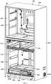
- FIG. 1 is a schematic front view of a refrigerator 10 according to an embodiment of the present invention.
- FIG. 2 is a schematic three-dimensional view of the refrigerator 10 shown in FIG. 1 .
- the refrigerator 10 may generally include a cabinet 100.
- the cabinet 100 includes a housing 110 and a storage liner arranged on an inner side of the housing 110.
- a space between the housing 110 and the storage liner is filled with a heat insulation material (to form a foamed layer).
- a storage compartment is defined in the storage liner.
- the storage liner may generally include a freezing liner 130, a variable-temperature liner 131, a refrigeration liner 120, etc.
- the storage compartment includes a freezing chamber 132 defined in the freezing liner 130 and a refrigeration chamber 121 defined in the refrigeration liner 120.
- a variable-temperature chamber 1311 is defined in the variable-temperature liner 131.
- a front side of the storage liner is also provided with a door to open or close the storage compartment. The door is o
- the refrigerator 10 of the present embodiment may further include an evaporator 101, an air supply fan (not shown), a compressor 104, a condenser 105, a throttling element (not shown) and the like.
- the evaporator 101 is connected to the compressor 104, the condenser 105 and the throttling element through a refrigerant pipeline to form a refrigeration cycle loop.
- the evaporator cools down when the compressor 104 is initiated to cool air flowing therethrough.
- the freezing liner 130 is located at a lower part of the cabinet 100, and a cooling chamber 200 located at the bottom is defined in the freezing liner.
- the evaporator 101 is arranged in the cooling chamber 200 to cool air flow entering the cooling chamber 200.
- the freezing chamber 132 defined by the freezing liner 130 is located above the cooling chamber 200 so that the cooling chamber 200 is located at the bottommost part of the cabinet 100.
- the evaporator 101 is of a flat cube shape as a whole arranged transversely in the cooling chamber 200. That is, a length-width surface of the evaporator 101 is parallel to a horizontal plane, a thickness surface of the evaporator is perpendicular to the horizontal plane, and the thickness size of the evaporator 101 is obviously less than the length size thereof.
- the evaporator 101 is transversely arranged in the cooling chamber 200 to avoid the evaporator 101 from occupying more space, thus ensuring a storage volume of the freezing chamber 132 above the cooling chamber 200.
- At least one front return air inlet communicated with the freezing chamber 132 is formed in a front side of the cooling chamber 200, so that return air flow of the freezing chamber 132 enters the cooling chamber 200 through the at least one front return air inlet to be cooled by the evaporator 101, and thus air flow circulation is formed between the cooling chamber 200 and the freezing chamber 132.
- the freezing chamber 132 is located at the bottommost part of the refrigerator 10, and a compressor chamber 300 is located at a rear part of the freezing chamber 132; thus the freezing chamber 132 is inevitably formed into a specially-shaped space for leaving a space for the compressor chamber 300, which reduces the storage volume of the freezing chamber 132 and brings the following problems.
- the freezing chamber 132 is located at a relatively low position, so that a user needs to bend down or squat much to access to the freezing chamber 132, which is inconvenient for a user, especially old people, to use.
- a depth of the freezing chamber 132 is reduced, so that in order to ensure the storage volume of the freezing chamber 132, the space in a height direction of the freezing chamber 132 needs to be enlarged. Therefore, the user needs to stack items in the height direction when placing the items to the freezing chamber 132, and it is inconvenient for the user to find them. Furthermore, the items located at a bottom of the freezing chamber 132 are tend to be blocked, so that it is not easy for the user to find them and the items are forgotten, resulting in deterioration and waste. Furthermore, the freezing chamber 132 is specially-shaped and is not a rectangular space, so it is inconvenient for those items which are relatively large in volume and not easy to segment to be placed in the freezing chamber 132.
- the cooling chamber 200 is defined in a bottom space of the freezing liner 130, and the freezing chamber 132 is defined above the cooling chamber 200, so that the cooling chamber 200 occupies a lower space in a freezing liner 130, the freezing chamber 132 is raised, the user has no need to bend down much to access to the freezing chamber 132, and the use experience is improved.
- the compressor chamber 300 may be located behind the cooling chamber 200, so that the freezing chamber 132 does not need to leave a space for the compressor chamber 300.
- the freezing chamber 132 is a rectangular space, so that the items can be stored in spread layout instead of stacked storage, which is convenient for the user to find an item and saves the time and energy of the user. Meanwhile, the items which are relatively large in volume and not easy to segment are convenient to place, and the problem that relatively large items cannot be placed in the freezing chamber 132 is solved.
- the air supply fan in the refrigerator 10 is arranged in the cooling chamber 200 and configured to suck the return air flow into the cooling chamber 200 to be cooled by the evaporator 101 and promote the cooled air flow to flow to the freezing chamber 132 and the variable-temperature chamber 1311.
- the refrigerator 10 of the present embodiment further includes a freezing chamber air supply duct 141 and a variable-temperature chamber air supply duct 1312.
- the freezing chamber air supply duct 141 communicates with an air outlet end of the air supply fan and is configured to convey part of the air flow cooled by the evaporator 101 into the freezing chamber 132.
- the freezing chamber air supply duct 141 is arranged on an inner side of a rear wall of the freezing liner 130 and has a plurality of air supply outlets 141a communicating with the freezing chamber 132.
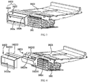
- FIG. 3 is a schematic three-dimensional view of partial components of the refrigerator 10 shown in FIG. 1 .
- the refrigerator 10 further includes a shield plate 102.
- the shield plate 102 includes a top cover 1021 located above the evaporator and at least one front cover group 1020. At least one of the front return air inlets aforementioned is formed in a front side of each front cover group 1020.
- the top cover 1021, the at least one front cover group 1020 and the rear wall, a bottom wall and two transverse side walls of the freezing liner 130 jointly define the cooling chamber 200.
- the transverse side walls of the freezing liner 130 form transverse side walls of the cooling chamber 200.
- the refrigerator 10 further includes a vertical division plate (not shown).
- the vertical division plate extends downwards from a top wall of the freezing liner 130 to an upper surface of the top cover 1021 to divide the freezing chamber 132 into two freezing spaces transversely distributed.
- a mounting slot 141c cooperating with the vertical division plate is formed in an air duct front cover plate of the freezing chamber air supply duct 141.
- the two front cover groups 1020 are distributed at an interval in the transverse direction.
- the vertical division plate includes a front blockage part extending to a position between the two front cover groups 1020 and located on a front side of the evaporator 101 to block a gap between the two front cover groups 1020, thereby completely isolating the air flows in the two freezing spaces of the freezing chamber 132, so that return air of the freezing space located on a transverse right side enters the cooling chamber 200 through the front return air inlet of the front cover group 1020 located on the transverse right side, and return air of the freezing space located on a transverse left side enters the cooling chamber 200 through the front return air inlet of the front cover group 1020 located on the transverse left side.
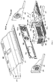
- FIG. 4 is a schematic exploded view of partial components of the refrigerator 10 shown in FIG. 3 .
- Two front return air inlets are formed in the front side of each front cover group 1020.
- the two front return air inlets are labeled as a first front return air inlet 102a and a second front return air inlet 102b respectively.
- Each front cover group 1020 includes a front decorative cover 1022 and a front air duct cover 1023.
- a front end part 10221 of the front decorative cover 1022 is located in front of a front end of the evaporator 101, and the front end part 10221 is spaced from the front end of the evaporator 101.
- a first opening 1022a is formed in a front wall of the front end part 10221 of the front decorative cover 1022.
- a rear side of the front end part 10221 of the front decorative cover 1022 is opened.
- a front end part 10231 of the front air duct cover 1023 is located at the front end of the evaporator 101.
- the front end part 10231 of the front air duct cover 1023 is inserted forwards into the front decorative cover 1022 from the opened part of the rear side of the front end part 10221 of the front decorative cover 1022 to divide the first opening 1022a into the first front return air inlet 102a located a lower side and the second front return air inlet 102b located at an upper side.
- a bottom wall of the front end part 10231 of the front air duct cover 1023 and a bottom wall of the front end part 10221 of the front decorative cover 1022 define a first return air passage connected to the first front return air inlet 102a, and the first return air passage is located in front of the evaporator 101.
- the front end part 10231 of the front air duct cover 1023 is inserted into the front decorative cover 1022 from the opened part of the rear side of the front end part 10221 of the front decorative cover 1022 to such an extent that the bottom wall of the front end part 10231 of the front air duct cover 1023 is spaced from the bottom wall of the front end part 10221 of the front decorative cover 1022 to form the first return air passage connected to the first front return air inlet 102a, such that at least part of the return air flow entering the first return air passage via the first front return air inlet 102a enters the evaporator 101 from the front of the evaporator 101 to be cooled by the evaporator 101.
- a second opening 1023 connected to the second front return air inlet 102b is formed in an upper section of the front end part 10231 of the front air duct cover 1023, and the second opening 1023a is located at an upper front side of the evaporator 101.
- a lower surface of the top cover 1021 is spaced apart from an upper surface of the evaporator 101, and a front end of the top cover 1021 is located at an upper rear side of the front end of the evaporator 101. That is, the top cover 1021 does not completely cover a position above the upper surface of the evaporator 101.
- an air shield material (not shown) is filled between the lower surface of the top cover 1021 and the upper surface of the evaporator 101, and the top cover 1021 and the upper surface of the evaporator 101 are spaced apart to form an interval space 102c.
- the interval space 102c is filled with the air shield material which may be air shield foam.
- the front air duct cover 1023 includes a first shielding part 10232 located at an upper rear side of the second opening 1023a.
- a rear end of the first shielding part 10232 abuts against the front end of the top cover 1021 to close the part above the upper surface of the evaporator 101 that is not shielded by the top cover 1021, so that a second return air passage connected to the second opening 1023a and the second front return air inlet 102b is formed between the first shielding part 10232 and the upper surface of the evaporator 101, and at least part of return air flow entering the second return air passage via the second front return air inlet 102b enters the evaporator 101 from the position above the evaporator 101 to be cooled by the evaporator.
- the front decorative cover 1022 includes a second shielding part 10222 bent and extending towards a rear upper side from the rear edge of the upper end of the front end part 10221.
- the second shielding part 10222 is located above the first shielding part 10232 and extends to be lap-jointed with the upper surface of the top cover 1021 to completely shield an upper side of the first shielding part 10232.
- the second shielding part 10222 has a shape that adapts to a shape of the first shielding part 10232 so that the second shielding part 10222 and the first shielding part 10232 are in close fit to avoid air leakage.
- a temperature around a front end surface of the evaporator 101 is greatly different from that of the return air flow, which easily causes frost on the front end surface of the evaporator 101. If the front end surface of the evaporator 101 is not frosted or is frosted a little, and the front end surface of the evaporator 101 can still allow air flow to pass, a part of the return air flow of the freezing chamber 132 enters the first return air passage via the first front return air inlet 102a, and another part of the return air flow of the freezing chamber enters the second return air passage via the second front return air inlet 102b.
- a part of air flow entering the first return air passage enters the evaporator 101 from the front of the evaporator 101 (i.e., the front end surface of the evaporator 101) to be cooed by the evaporator 101, and another part of the air flow entering the first return air passage flows up to the second return air passage and flows down through the second return air passage to enter the evaporator 101, so that part of the return air flow enters the evaporator 101 from the front of the evaporator 101, and part of the return air flow enters the evaporator 101 from an upper side of the evaporator 101, so as to ensure full heat exchange between the return air flow and the evaporator 101 to enhance the refrigeration effect of the refrigerator 10.
- the return air flow of the freezing chamber 132 may enter the second return air passage via the second front return air inlet 102b located above and flow down through the second return air passage to enter the evaporator 101 to be cooled from the upper surface of the evaporator 101, which can still ensure the refrigeration effect of the refrigerator 10.
- the heat exchange efficiency of the return air flow of the freezing chamber 132 and the evaporator 101 is guaranteed, and the refrigeration effect of the refrigerator 10 is enhanced.
- the front end surface of the evaporator 101 when the front end surface of the evaporator 101 is frosted, it can still ensure that the return air flow can enter the evaporator 101 to be cooled by the evaporator 101, so that the problem of reduction in the refrigeration effect of the existing refrigerant 10 caused by the frosting of the evaporator 101 is solved, and the overall performance of the refrigerator 10 is improved.
- the refrigeration liner 120 is located above the variable-temperature liner 131, and a refrigeration chamber 121 is defined in the refrigeration liner 120.
- the refrigerator 10 of the present embodiment further includes a refrigeration evaporator (not shown), a refrigeration fan (not shown) and a refrigeration air supply duct (not shown).
- a refrigeration evaporator chamber is defined at a lower part on the inner side of the rear wall of the refrigeration liner 120. The refrigeration evaporator and the refrigeration fan are arranged in the refrigeration evaporator chamber.
- the refrigeration air supply duct is arranged on the inner side of the rear wall of the refrigeration liner 120, and has a refrigeration air supply inlet communicated with an air outlet end of the refrigeration fan and a refrigeration air supply outlet communicated with the refrigeration chamber 121.
- the refrigeration fan is configured to promote the air flow cooled by the refrigeration evaporator to flow through the refrigeration air supply duct into the refrigeration chamber 121 to adjust a temperature of the refrigeration chamber 121.
- At least one refrigeration return air inlet is formed in a front side of the refrigeration evaporator chamber to guide, through the refrigeration return air inlet, return air flow of the refrigeration chamber 121 into the refrigeration evaporator chamber to be cooled by the refrigeration evaporator, thereby forming air flow circulation between the refrigeration chamber 121 and the refrigeration evaporator chamber.
- the temperature in the refrigeration chamber 121 is generally between 2°C and 10°C, preferably 4°C to 7°C.
- a temperature in the freezing chamber 132 is generally from -22°C to -14°C.
- the variable-temperature chamber 1311 may be adjusted to -18°C to 8°C at will.
- Different types of items have different optimal storage temperatures, and are suitable for being stored at different positions. For example, fruits and vegetables are suitable for being stored in the refrigeration chamber 121, and meats are suitable for being stored in the freezing chamber 132.
- FIG. 5 is a schematic partial cross-sectional view of the refrigerator 10 shown in FIG. 1 .
- FIG. 6 is a schematic exploded view of a compressor chamber 300 of the refrigerator 10 shown in FIG. 1 .
- Fig. 7 is a schematic partial enlarged view of FIG. 6 .
- FIG. 8 is a schematic bottom view of the compressor chamber 300 of the refrigerator 10 shown in FIG. 6 .
- the compressor chamber 300 is defined at a bottom of the cabinet 100, and the compressor chamber 300 is located behind the cooling chamber 200, so that the whole compressor chamber 300 is located below the freezing chamber 132.
- the refrigerator 10 further includes a heat dissipation fan 106.
- the heat dissipation fan 106 may be an axial flow fan.
- the compressor 104, the heat dissipation fan 106, and the condenser 105 are sequentially arranged in the compressor chamber 300 at intervals in a transverse direction.
- At least one rear air outlet hole 1162a is formed in a section 1162 of a rear wall of the compressor chamber 300 corresponding to the compressor 104.
- a rear air inlet hole facing the condenser 105 and a rear air outlet hole 1162a facing the compressor 104 are formed in the rear wall of the compressor chamber 300, and the circulation of heat dissipation air flow is completed at a rear part of the compressor chamber 300.
- ventilation holes are respectively formed in a front wall and the rear wall of the compressor chamber 300 to form a heat dissipation air circulation path in the front-rear direction.
- those skilled in the art generally increase the number of rear air inlet holes and rear air outlet holes 1162a in the rear wall of the compressor chamber 300 to enlarge a ventilation area, or enlarge a heat exchange area of the condenser 105.
- a U-shaped condenser with a larger heat exchange area is used.
- a conventional design solution of enlarging the heat exchange area of the condenser 105 and the ventilation area of the compressor chamber 300 non-uniform heat dissipation of the condenser 105 is caused, and a refrigerating system of the refrigerator 10 is adversely affected.
- a bottom air inlet 110a close to the condenser 105 and a bottom air outlet 110b close to the compressor 104 are defined at a bottom wall of the cabinet to complete a circulation of the heat dissipation air flow at a bottom of the refrigerator 10.
- the space between the refrigerator 10 and a supporting surface is fully used, a distance between the rear wall of the refrigerator 10 and a cupboard does not need to be increased, a space occupied by the refrigerator 10 is reduced and good heat dissipation of the compressor chamber 300 is ensured. Therefore, the problem that heat dissipation of the compressor chamber 300 and space occupation of an embedded refrigerator 10 cannot be balanced is fundamentally solved, and it is of particularly important significance.
- Supporting rollers 900 may also be arranged at four corners of the bottom wall of the cabinet 100, and the cabinet 100 is placed on the supporting surface through the four supporting rollers 900, with a certain space being formed between the bottom wall of the cabinet 100 and the supporting surface.
- the heat dissipation fan 106 is configured to promote environmental air around the bottom air inlet 110a to enter the compressor chamber 300 from the bottom air inlet 110a, sequentially pass through the condenser 105 and the compressor 104, and then flow from the bottom air outlet 110b into an external environment to dissipate heat from the compressor 104 and the condenser 105.
- a surface temperature of the condenser 105 is generally less than that of the compressor 104, and thus the external air cools the condenser 105 first and then cools the compressor 104 in the process above.
- a plate section 1161 of a back plate 116 (the rear wall of the compressor chamber 300) facing the condenser 105 is a continuous plate surface. That is, the plate section 1161 of the back plate 116 facing the condenser 105 is provided with no heat dissipation hole.
- the applicant broken through the conventional design idea to design the plate section 1161 of the rear wall (the back plate 116) of the compressor chamber 300 corresponding to the condenser 105 as the continuous plate surface, so that the heat dissipation air flow entering the compressor chamber 300 is sealed at the condenser 105 to enable more environmental air entering from the bottom air inlet 110a to be concentrated at the condenser 105, which ensures the heat exchange uniformity of each condensation section of the condenser 105 and is favorable for forming the better heat dissipation air flow path and also achieving a relatively good heat dissipation effect.
- the plate section 1161 of the back plate 116 facing the condenser 105 is the continuous plate surface and is provided with no air inlet hole, so that the problems that in conventional design, air exhaust and air feeding are both concentrated at the rear part of the compressor chamber 300, which causes that the hot air blown from the compressor chamber 300 enters the compressor chamber 300 again without being cooled by the environmental air in time, causing adverse effects on heat exchange of the condenser 105 are avoided, and thus the heat exchange efficiency of the condenser 105 is guaranteed.
- two transverse side walls of the compressor chamber 300 are each provided with a side ventilation hole, and the side ventilation hole may be covered with a ventilation cover plate 108.
- Small grille type ventilation holes are formed in the ventilation cover plate 108.
- the housing of the refrigerator 10 includes two cabinet side plates 111 in a transverse direction.
- the two cabinet side plates 111 vertically extend to form two side walls of the refrigerator 10.
- the two cabinet side plates 111 are each provided with a side opening 111a communicated with the corresponding side ventilation hole, so that the heat dissipation air flow flows out of the refrigerator 10. Therefore, a heat dissipation path is further extended, and the heat dissipation effect of the compressor chamber 300 is guaranteed.
- the condenser 105 includes a first straight section 1051 transversely extending, a second straight section 1052 extending in a front-rear direction, and a transition curved section (not shown) for connecting the first straight section 1051 to the second straight section 1052, thereby forming an L-shaped condenser 105 with a proper heat exchange area.
- the plate section 1161 of the rear wall (the back plate 116) of the above-mentioned compressor chamber 300 corresponding to the condenser 105 is the plate section 1161 of the back plate 116 facing the first straight section 1051.
- the environmental air flow entering from the side ventilation holes exchanges heat directly with the second straight section 1052, and the environmental air entering from the bottom air inlet 110a exchanges heat directly with the first straight section 1051. Therefore, more environmental air entering the compressor chamber 300 is further concentrated at the condenser 105 to ensure the overall heat dissipation uniformity of the condenser 105.
- the cabinet 100 further includes a specially-shaped plate 400, a supporting plate 112 and two side plates 119.
- the specially-shaped plate 400 includes a bottom horizontal section 113 located at a front side of the bottom and a bent section 401 bending and extending towards a rear upper side from a rear end of the bottom horizontal section 113.
- the bent section 401 extends to a position above the supporting plate 112.
- the supporting plate 112 and the bottom horizontal section 113 jointly form the bottom wall of the cabinet 100.
- the two side plates 119 extend upwards from two transverse sides of the supporting plate 112 to two transverse sides of the bent section 401 respectively to close two transverse sides of the compressor chamber 300 to form two transverse side walls of the compressor chamber 300.
- the back plate 116 extends upwards from a rear end of the supporting plate 112 to a rear end of the bent section 401 to form the rear wall of the compressor chamber 300.
- FIG. 10 is a schematic three-dimensional view of the supporting plate 112 of the refrigerator 10 shown in FIG. 6 .
- the supporting plate 112 includes a first section 1121 and a second section 1122 extending forwards from a front end of the first section 1121.
- the compressor 104, the heat dissipation fan 106 and the condenser 105 are sequentially arranged on the first section 1121 of the supporting plate 112 at intervals in a transverse direction and are located in a space defined by the supporting plate 112, the two side plates 119, the back plate 116 and the bent section 401.
- a front end of the second section 1122 is connected to the bottom horizontal section 113, and in the transverse direction, at an interval, the bottom air inlet 110a is formed in the side of the second section close to the condenser 105 and the bottom air outlet 110b is formed in the side of the second section close to the compressor 104.
- the supporting plate 112 and the specially-shaped plate 400 are arranged such that the supporting plate 112 and the bottom horizontal section 113 jointly form the bottom wall of the cabinet 100, and a front end part of the supporting plate 112 is provided with the bottom air inlet 110a and the bottom air outlet 110b.
- the bottom air inlet 110a and the bottom air outlet 110b are composed of a plurality of ventilation holes respectively, so that the refrigerator 10 is anti-mouse. Meanwhile, this structure can greatly simplify an installation process of the refrigerator 10, i.e., only the compressor 104, the heat dissipation fan 106, the condenser 105, and the like need to be integrated on the supporting plate 112, and then the supporting plate 112 and the specially-shaped plate 400 are integrated to complete the installation of the bottom wall of the cabinet 100.
- FIG. 11 is a schematic side view of the supporting plate 112 of the refrigerator 10 shown in FIG. 10 .
- the first section 1121 is substantially horizontal
- the second section 1122 is substantially horizontal.
- FIG. 12 is a schematic side view of a supporting plate 112 of a refrigerator 10 according to another embodiment of the present invention.
- the first section 1121 is substantially horizontal
- the second section 1122 has a first part 11221 and a second part 11222.
- the first part 11221 is formed by extending from the front end of the first section 1121 to a front upper side
- the second part 11222 is formed by extending from a front end of the first part 11221 to a front lower side.
- an included angle between the first part 11221 and a horizontal plane is less than 45°.
- the included angle between the first part 11221 and the horizontal plane is 20° to 30°.
- the bent section 401 includes a first inclined section 1131, a second inclined section 114, a third inclined section 402, and a top horizontal section 115.
- the first inclined section 1131 extends upwards from a rear end of the bottom horizontal section 113
- the second inclined section 114 extends from an upper end of the first inclined section 1131 to a rear upper side
- the third inclined section 402 extends from an upper end of the second inclined section 114 to a rear upper side
- the top horizontal section 115 extends backwards from an upper end of the third inclined section 402 to the back plate 116 to shield upper sides of the compressor 104, the heat dissipation fan 106 and the condenser 105.
- a slope structure of the bent section 401 is capable of guiding and rectifying feed air flow, so that the air flow entering from the bottom air inlet 110a flows more concentratedly to the condenser 105, avoiding that the air flow is too dispersed to pass more through the condenser 105, thereby further ensuring the heat dissipation effect of the condenser 105.
- the slope structure of the bent section 401 guides exhaust air flow from the bottom air outlet 110b to a front side of the bottom air outlet, so that the exhaust air flow flows out of the compressor chamber 300 more smoothly, and thus the smoothness of air flow circulation is further improved.
- the included angle between the first inclined section 1131 and the horizontal plane is slightly less than 90°, and an included angle between the second inclined section 114 and the horizontal plane and an included angle between the third inclined section 402 and the horizontal plane are both less than 45°.
- the slope structure of the bent section 401 has better guiding and rectifying effect on the air flow. Furthermore, it is unexpected that the applicant creatively recognized that the slope structure of the bent section 401 achieves relatively good suppression effect on air flow noise. In prototype testing, the noise of the compressor chamber 300 with the foregoing particularly designed slope structure can be reduced by 0.65 decibel or above.
- the bottom of the cabinet 100 of the traditional refrigerator 10 is usually an integrated carrying plate with a substantially flat plate type structure.
- the compressor 104 is arranged on an inner side of the carrying plate. Vibration generated in the operation of the compressor 104 has great impact on the bottom of the cabinet 100.
- the bottom of the cabinet 100 is a three-dimensional structure formed by the specially-shaped plate 400 of a special structure and the supporting plate 112 to provide an independent three-dimensional space for arranging the compressor 104.
- the supporting plate 112 is used to carry the compressor 104 to reduce the influence of the vibration of the compressor 104 on other components at the bottom of the cabinet 100.
- the cabinet 100 is designed into the above ingenious special structure, so that the bottom of the refrigerator 10 is compact in structure and reasonable in layout, and the overall volume of the refrigerator 10 is reduced. Meanwhile, the space at the bottom of the refrigerator 10 is fully used, and the heat dissipation efficiency of the compressor 104 and the condenser 105 is guaranteed.
- FIG. 9 is a schematic top view of the compressor chamber 300 of the refrigerator 10 shown in FIG. 6 .
- a gap is reserved between the front end surface of the condenser 105 and the bottom air inlet 110a, which means that the condenser 105 is shifted back under the condition that the position of the heat dissipation air inlet does not change.
- Those skilled in the art usually set the condenser 105 to be close to the heat dissipation air inlet as much as possible in a front-rear direction to save the space.
- shifting the condenser 105 backwards can allow appropriate size reduction of the condenser 105, thereby saving more space.
- a distance L between the front end surface of the condenser 105 and the bottom air inlet 110a is not less than 10 cm, preferably 10 to 50 cm.
- a particular distance is reserved between the front end surface of the condenser 105 and the bottom air inlet 110a, which can reduce feed turbulence and reduce air feed resistance. The air feed volume is increased, and the feed air flow noise is reduced.
- an evaporating dish 600 of the refrigerator 10 is of a substantially cubic structure having an opening in the top, and has a bottom wall and four side walls extending upwards from the bottom wall.
- Supporting blocks 620 are respectively provided on the bottom wall of the evaporating dish 600 corresponding to the first straight section 1051 and the second straight section 1052 of the condenser 105.
- the bottom wall of the evaporating dish 600 is provided with two supporting blocks 620 spaced in the transverse direction, and the bottom wall of the evaporating dish 600 is provided with one supporting block 620 in a vertical direction.
- the condenser 105 is provided with a supporting piece 1053 at its bottom.
- the supporting piece 1053 is fixed to the supporting block 620 to fix the condenser 105 in the evaporating dish 600, so that a lower end of a bottom of the condenser 105 is higher than a top end of a front wall of the evaporating dish 600.
- the bottom of the condenser 105 is also exposed to external air flow, further guaranteeing the heat dissipation effect of the condenser 105.
- FIG. 13 is a schematic top view of partial components of the compressor chamber 300 of the refrigerator 10 shown in FIG. 6 .
- the refrigerator 10 further includes a divider 117 configured to completely isolate the bottom air inlet 110a from the bottom air outlet 110b to allow external air to enter the compressor chamber 300 via the bottom air inlet 110a located on one transverse side of the divider 117 under the action of the heat dissipation fan 106, sequentially flow through the condenser 105 and the compressor 104, and finally flow out from the bottom air outlet 110b located on the other transverse side of the divider 117, such that the external air entering the condenser 105 and heat dissipation air discharged from the compressor 104 are not crossed.
- the refrigerator 10 further includes a fan fixing frame 500.
- the fan fixing frame 500 is fixed in the compressor chamber 300 in a front-rear direction and used to fix the heat dissipation fan 106.
- the divider 117 is fixed to the fan fixing frame 500, so that on one hand, the installation stability of the divider 117 can be guaranteed; and on the other hand, noise generated by vibration of the heat dissipation fan 106 can be reduced.
- the divider 117 is also fixed to the evaporating dish 600. In this way, the installation stability of the divider 117 can be further improved.
- the divider 117 is arranged behind the bent section 401, and a front part thereof is connected to the rear end of the bottom horizontal section 113, and a rear part thereof is fixed to the fan fixing frame 500 and the evaporating dish 600 respectively.
- FIG. 14 is a schematic cross-sectional view along Line A-A of FIG. 13 .
- FIG. 15 is a schematic cross-sectional view along Line B-B of FIG. 13 .
- FIG. 16 is a schematic three-dimensional view of the divider 117 of the refrigerator 10 shown in FIG. 6 .
- the divider 117 has a first separation part 901, a second separation part 902 and a bottom connection part 903 therebetween.
- a rear part 911 of the first separation part 901 includes a main body part 9113, a first flange 9111 and a second flange 9112.
- An accommodating slot 9114 is formed in the main body part 9113.
- the first flange 9111 and the second flange 9112 are formed by extending backwards from left and right sides of a rear end of the main body part 9113 respectively.
- a front part of the fan fixing frame 500 is clamped between the first flange 9111 and the second flange 9112.
- a front end of the fan fixing frame 500 extends forwards to form a protrusion 510.
- the protrusion 510 of the fan fixing frame 500 is fitted in the accommodating slot 9114 to realize snap fixing between the divider 117 and the fan fixing frame 500.
- a rear part 921 of the second separation part 902 includes a main body part 9212 and a flange 9211 formed by extending backwards on the side of the main body part 9212 close to the evaporating dish 600.
- a lower part of the main body part 9212 is recessed forwards to form a horizontal abutting surface 9213.
- a protrusion 610 extending forwards is formed on a front wall of the evaporating dish 600, and the protrusion 610 of the evaporating dish 600 is fitted below the horizontal abutting surface 9213 to realize fixing of the divider 117 and the evaporating dish 600 by abutting against each other.
- a plurality of claws 930 extending downwards are formed on the bottom connection part 903, and the supporting plate 112 is provided with clamping holes at corresponding positions.
- the divider 117 is fixed to the supporting plate 112 by fixing the claws 930 in the clamping holes.
- the baffle plate 800 is provided between the rear part 921 of the second separation part 902 and the first straight section 1051 of the condenser 105.
- the baffle plate 800 may be an integral part or a split assembly, as long as it can shield the gap between the front end surface of the condenser 105 and the divider 117.
- a notch 904 is formed among the first separation part 901, the second separation part 902, and the bottom connection part 903 to provide a space for connecting a water guide pipe 700 of the refrigerator 10 to the evaporating dish 600.
- the divider 117 is preferably an integrally molded plastic part, which can simplify the production process and installation process of the divider 117.
- the upper end of the condenser 105, the upper end of the fan fixing frame 500, and an upper end of the divider 117 are further provided with an air shield member 1056, respectively.
- the air shield member 1056 may be air shield sponge, which charges a space between the upper end of the condenser 105 and the bent section 401, a space between the upper end of the fan fixing frame 500 and the bent section and a space between the upper end of the divider 117 and the bent section respectively.
- the air shield member 1056 covers the upper ends of the first straight section 1051, the second straight section 1052, and the transition curved section, and the upper end of the air shield member 1056 abuts against an inner surface of the bent section 401 to seal the upper end of the condenser 105, so as to prevent part of the air entering the compressor chamber 300 from passing through the space between the upper end of the condenser 105 and the bent section 401, instead of passing through the condenser 105, so that the air entering the compressor chamber 300 exchanges heat through the condenser 105 as much as possible to further enhance the heat dissipation effect of the condenser 105.
- the air shield member 1056 covers the upper end of the fan fixing frame 500, and the upper end of the air shield member 1056 abuts against the inner surface of the bent section 401.
- the air shield member 1056 covers the upper ends of the first separation part 901 and the second separation part 902, and the upper end of the air shield member 1056 abuts against the inner surface of the bent section 401.
- the refrigerator 10 further includes an air shield bar 107 extending in the front-rear direction.
- the air shield bar 107 is located between the bottom air inlet 110a and the bottom air outlet 110b, and extends from a lower surface of the bottom horizontal section 113 to a lower surface of the supporting plate 112, so that when the refrigerator 10 is placed on a supporting surface, it transversely divides a space between the bottom wall of the cabinet 100 and the supporting surface, so as to allow the external air to enter the compressor chamber 300 via the bottom air inlet 110a located on one transverse side of the air shield bar 107 under the action of the heat dissipation fan 106, sequentially flow through the condenser 105 and the compressor 104, and finally flow out from the bottom air outlet 110b located on the other transverse side of the air shield bar 107, thereby completely isolating the bottom air inlet 110a from the bottom air outlet 110b, ensuring that the external air entering the condenser 105 and the heat dissipation air discharged from the compressor
- the cooling chamber 200 is defined in the bottom, and the freezing chamber 132 is defined above the cooling chamber 200, so that the cooling chamber 200 occupies a lower space in the freezing liner 130, the freezing chamber 132 is raised, the user has no need to bend down much to access to the freezing chamber 132, and the use experience is improved.
- the divider 117 the bottom air inlet 110a and the bottom air outlet 110b are completely separated, so that the external air entering the condenser 105 and the heat dissipation air discharged from the compressor 104 are not crossed.
- the divider 117 of the refrigerator 10 of the embodiments of the present invention is fixed to the fan fixing frame 500, so that on one hand, the installation stability of the divider 117 can be guaranteed; and on the other hand, noise generated by vibration of the heat dissipation fan 106 can be reduced.
- the divider 117 of the refrigerator 10 of the embodiments of the present invention is also fixed to the evaporating dish 600 and the supporting plate 112, and is convenient to install and stable.
Landscapes
- Engineering & Computer Science (AREA)
- Chemical & Material Sciences (AREA)
- Combustion & Propulsion (AREA)
- Physics & Mathematics (AREA)
- Mechanical Engineering (AREA)
- Thermal Sciences (AREA)
- General Engineering & Computer Science (AREA)
- Cold Air Circulating Systems And Constructional Details In Refrigerators (AREA)
- Devices That Are Associated With Refrigeration Equipment (AREA)
Abstract
Description
- The present invention relates to the technical field of household appliances, and particularly relates to a refrigerator with a divider between a bottom air inlet and a bottom air outlet.
- In an existing refrigerator, a freezing chamber is generally located at a lower part of the refrigerator; a cooling chamber is located at a rear part of an outer side of the freezing chamber; and a compressor chamber is located behind the freezing chamber. The freezing chamber needs to leave a space for the compressor chamber, so that the freezing chamber is specially shaped, which limits a depth of the freezing chamber.
- An objective of the present invention is to provide a refrigerator in which a bottom air inlet and a bottom air outlet are completely separated.
- A further objective of the present invention is to reduce noise generated by vibration of a heat dissipation fan.
- A still further objective of the present invention is to stably fix a divider.
- Particularly, the present invention provides a refrigerator, including:
- a cabinet in which a cooling chamber located at a lower side and at least one storage compartment located above the cooling chamber are defined, a bottom air inlet and a bottom air outlet being formed in a bottom of the cabinet in a transverse direction at an interval;
- a compressor chamber arranged behind the cooling chamber, in which a compressor, a heat dissipation fan and a condenser are sequentially arranged; and
- a divider configured to completely separate the bottom air inlet from the bottom air outlet to allow external air to enter the compressor chamber via the bottom air inlet located at one transverse side of the divider under the action of the heat dissipation fan, sequentially flow through the condenser and the compressor, and finally flow out from the bottom air outlet located on the other transverse side of the divider, such that the external air entering the condenser and heat dissipation air discharged from the compressor are not crossed.
- Optionally, the refrigerator further includes a fan fixing frame fixed in the compressor chamber in a front-rear direction and used to fix the heat dissipation fan. The divider is fixed to the fan fixing frame.
- Optionally, the divider is snap-fixed to the fan fixing frame.
- Optionally, the divider has a first separation part, and an accommodating slot is formed in a rear end of the first separation part; a front end of the fan fixing frame extends forwards to form a protrusion; and the protrusion of the fan fixing frame is fitted in the accommodating slot to realize snap fixing between the divider and the fan fixing frame.
- Optionally, a rear part of the first separation part includes a main body part, a first flange and a second flange, the accommodating slot is formed in the main body part, and the first flange and the second flange are formed by extending backwards from left and right sides of a rear end of the main body part respectively; and a front part of the fan fixing frame is clamped between the first flange and the second flange.
- Optionally, the refrigerator further includes an evaporating dish fixed in the compressor chamber; the condenser is arranged in the evaporating dish; and the divider is fixed to the evaporating dish.
- Optionally, the divider is fixed to the evaporating dish by abutting against each other.
- Optionally, the divider has a second separation part, and a lower part of a rear end of the second separation part is sunken forwards to form a horizontal abutting surface; a front wall of the evaporating dish extends forwards to form a protrusion; and the protrusion of the evaporating dish is fitted below the horizontal abutting surface to realize fixing of the divider and the evaporating dish by abutting against each other.
- Optionally, the refrigerator further includes a supporting plate configured to be bottoms of the cabinet and the compressor chamber; the divider is provided with a plurality of claws at its bottom; the supporting plate is correspondingly provided with a plurality of clamping holes; and the plurality of claws are fixed to the plurality of clamping holes so that the divider is fixed to the supporting plate.
- Optionally, the divider is an integrally molded piece.
- Optionally, the refrigerator further includes:
an evaporator arranged in the cooling chamber and configured to cool an air flow entering the cooling chamber. - In the refrigerator of the present invention, the cooling chamber occupies a lower space in a freezing liner by defining the cooling chamber at the bottom, so that the freezing chamber is raised, a user has no need to bend down much to access to the freezing chamber, and the use experience is improved. In addition, by the divider, the bottom air inlet and the bottom air outlet are completely separated, so that external air entering the condenser and heat dissipation air discharged from the compressor are not crossed.
- Further, in the refrigerator of the present invention, the divider is fixed to the fan fixing frame; thus on one hand, the installation stability of the divider can be guaranteed, and on the other hand, noise generated by vibration of the heat dissipation fan can be reduced.
- Further, in the refrigerator of the present invention, the divider is also fixed to the evaporating dish and the supporting plate, and is convenient to install and stable.
- The above, as well as other objectives, advantages, and features of the present invention, will be better understood by those skilled in the art according to the following detailed description of specific embodiments of the present invention taken in conjunction with the accompanying drawings.
- In the following part, some specific embodiments of the present invention will be described in detail in an exemplary rather than limited manner with reference to the accompanying drawings. The same reference numerals in the accompanying drawings indicate the same or similar components or parts. Those skilled in the art should understand that these accompanying drawings are not necessarily drawn to scale. In the drawings:
-
FIG. 1 is a schematic front view of a refrigerator according to an embodiment of the present invention. -
FIG. 2 is a schematic three-dimensional view of the refrigerator shown inFIG. 1 -
FIG. 3 is a schematic three-dimensional view of partial components of the refrigerator shown inFIG. 1 . -
FIG. 4 is a schematic exploded view of partial components of the refrigerator shown inFIG. 3 . -
FIG. 5 is a schematic partial cross-sectional view of the refrigerator shown inFIG. 1 . -
FIG. 6 is a schematic exploded view of a compressor chamber of the refrigerator shown inFIG. 1 . -
Fig. 7 is a schematic partial enlarged view ofFIG. 6 . -
FIG. 8 is a schematic bottom view of a compressor chamber of the refrigerator shown inFIG. 6 . -
FIG. 9 is a schematic top view of a compressor chamber of the refrigerator shown inFIG. 6 . -
FIG. 10 is a schematic three-dimensional view of a supporting plate of the refrigerator shown inFIG. 6 . -
FIG. 11 is a schematic side view of the supporting plate of the refrigerator shown inFIG. 10 . -
FIG. 12 is a schematic side view of a supporting plate of a refrigerator according to another embodiment of the present invention. -
FIG. 13 is a schematic top view of partial components of the compressor chamber of the refrigerator shown inFIG. 6 . -
FIG. 14 is a schematic cross-sectional view along Line A-A ofFIG. 13 . -
FIG. 15 is a schematic cross-sectional view along Line B-B ofFIG. 13 . -
FIG. 16 is a schematic three-dimensional view of a divider of the refrigerator shown inFIG. 6 . - The present embodiment provides a
refrigerator 10. In the following description, the orientation or positional relationship indicated by "front", "rear", "upper", "lower", "left", "right", etc. are based on the orientation of therefrigerator 10 itself as a reference. "Front" and "rear" refers to the direction indicated inFIG. 6 . As shown inFIG. 1 , "transverse" refers to a direction parallel to a width direction of therefrigerator 10. "Left" refers to the transverse left side of the refrigerator with reference to therefrigerator 10. "Right" refers to the transverse right side of the refrigerator with reference to therefrigerator 10. -
FIG. 1 is a schematic front view of arefrigerator 10 according to an embodiment of the present invention.FIG. 2 is a schematic three-dimensional view of therefrigerator 10 shown inFIG. 1 . Therefrigerator 10 may generally include acabinet 100. Thecabinet 100 includes ahousing 110 and a storage liner arranged on an inner side of thehousing 110. A space between thehousing 110 and the storage liner is filled with a heat insulation material (to form a foamed layer). A storage compartment is defined in the storage liner. The storage liner may generally include afreezing liner 130, a variable-temperature liner 131, arefrigeration liner 120, etc. The storage compartment includes a freezingchamber 132 defined in the freezingliner 130 and arefrigeration chamber 121 defined in therefrigeration liner 120. A variable-temperature chamber 1311 is defined in the variable-temperature liner 131. A front side of the storage liner is also provided with a door to open or close the storage compartment. The door is omitted inFIG. 1 andFIG. 2 . - Those skilled in the art can realize that the
refrigerator 10 of the present embodiment may further include anevaporator 101, an air supply fan (not shown), acompressor 104, acondenser 105, a throttling element (not shown) and the like. Theevaporator 101 is connected to thecompressor 104, thecondenser 105 and the throttling element through a refrigerant pipeline to form a refrigeration cycle loop. The evaporator cools down when thecompressor 104 is initiated to cool air flowing therethrough. In the present embodiment, the freezingliner 130 is located at a lower part of thecabinet 100, and acooling chamber 200 located at the bottom is defined in the freezing liner. Theevaporator 101 is arranged in thecooling chamber 200 to cool air flow entering thecooling chamber 200. The freezingchamber 132 defined by the freezingliner 130 is located above the coolingchamber 200 so that thecooling chamber 200 is located at the bottommost part of thecabinet 100. Specifically, theevaporator 101 is of a flat cube shape as a whole arranged transversely in thecooling chamber 200. That is, a length-width surface of theevaporator 101 is parallel to a horizontal plane, a thickness surface of the evaporator is perpendicular to the horizontal plane, and the thickness size of theevaporator 101 is obviously less than the length size thereof. Theevaporator 101 is transversely arranged in thecooling chamber 200 to avoid the evaporator 101 from occupying more space, thus ensuring a storage volume of the freezingchamber 132 above the coolingchamber 200. At least one front return air inlet communicated with the freezingchamber 132 is formed in a front side of thecooling chamber 200, so that return air flow of the freezingchamber 132 enters thecooling chamber 200 through the at least one front return air inlet to be cooled by theevaporator 101, and thus air flow circulation is formed between the coolingchamber 200 and the freezingchamber 132. - In a
traditional refrigerator 10, the freezingchamber 132 is located at the bottommost part of therefrigerator 10, and acompressor chamber 300 is located at a rear part of the freezingchamber 132; thus the freezingchamber 132 is inevitably formed into a specially-shaped space for leaving a space for thecompressor chamber 300, which reduces the storage volume of the freezingchamber 132 and brings the following problems. In one aspect, the freezingchamber 132 is located at a relatively low position, so that a user needs to bend down or squat much to access to the freezingchamber 132, which is inconvenient for a user, especially old people, to use. In another aspect, a depth of the freezingchamber 132 is reduced, so that in order to ensure the storage volume of the freezingchamber 132, the space in a height direction of the freezingchamber 132 needs to be enlarged. Therefore, the user needs to stack items in the height direction when placing the items to the freezingchamber 132, and it is inconvenient for the user to find them. Furthermore, the items located at a bottom of the freezingchamber 132 are tend to be blocked, so that it is not easy for the user to find them and the items are forgotten, resulting in deterioration and waste. Furthermore, the freezingchamber 132 is specially-shaped and is not a rectangular space, so it is inconvenient for those items which are relatively large in volume and not easy to segment to be placed in the freezingchamber 132. In therefrigerator 10 of the present embodiment, the coolingchamber 200 is defined in a bottom space of the freezingliner 130, and the freezingchamber 132 is defined above the coolingchamber 200, so that thecooling chamber 200 occupies a lower space in a freezingliner 130, the freezingchamber 132 is raised, the user has no need to bend down much to access to the freezingchamber 132, and the use experience is improved. Meanwhile, thecompressor chamber 300 may be located behind thecooling chamber 200, so that the freezingchamber 132 does not need to leave a space for thecompressor chamber 300. The freezingchamber 132 is a rectangular space, so that the items can be stored in spread layout instead of stacked storage, which is convenient for the user to find an item and saves the time and energy of the user. Meanwhile, the items which are relatively large in volume and not easy to segment are convenient to place, and the problem that relatively large items cannot be placed in the freezingchamber 132 is solved. - In some embodiments, the air supply fan in the
refrigerator 10 is arranged in thecooling chamber 200 and configured to suck the return air flow into thecooling chamber 200 to be cooled by theevaporator 101 and promote the cooled air flow to flow to the freezingchamber 132 and the variable-temperature chamber 1311. Therefrigerator 10 of the present embodiment further includes a freezing chamberair supply duct 141 and a variable-temperature chamberair supply duct 1312. The freezing chamberair supply duct 141 communicates with an air outlet end of the air supply fan and is configured to convey part of the air flow cooled by theevaporator 101 into the freezingchamber 132. The freezing chamberair supply duct 141 is arranged on an inner side of a rear wall of the freezingliner 130 and has a plurality ofair supply outlets 141a communicating with the freezingchamber 132. -
FIG. 3 is a schematic three-dimensional view of partial components of therefrigerator 10 shown inFIG. 1 . In some embodiments, therefrigerator 10 further includes ashield plate 102. Theshield plate 102 includes atop cover 1021 located above the evaporator and at least onefront cover group 1020. At least one of the front return air inlets aforementioned is formed in a front side of eachfront cover group 1020. Thetop cover 1021, the at least onefront cover group 1020 and the rear wall, a bottom wall and two transverse side walls of the freezingliner 130 jointly define thecooling chamber 200. Correspondingly, the transverse side walls of the freezingliner 130 form transverse side walls of thecooling chamber 200. In the present embodiment, there are twofront cover groups 1020, and the twofront cover groups 1020 are distributed in a transverse direction. In the present embodiment, therefrigerator 10 further includes a vertical division plate (not shown). The vertical division plate extends downwards from a top wall of the freezingliner 130 to an upper surface of thetop cover 1021 to divide the freezingchamber 132 into two freezing spaces transversely distributed. A mountingslot 141c cooperating with the vertical division plate is formed in an air duct front cover plate of the freezing chamberair supply duct 141. In the present embodiment, the twofront cover groups 1020 are distributed at an interval in the transverse direction. The vertical division plate includes a front blockage part extending to a position between the twofront cover groups 1020 and located on a front side of theevaporator 101 to block a gap between the twofront cover groups 1020, thereby completely isolating the air flows in the two freezing spaces of the freezingchamber 132, so that return air of the freezing space located on a transverse right side enters thecooling chamber 200 through the front return air inlet of thefront cover group 1020 located on the transverse right side, and return air of the freezing space located on a transverse left side enters thecooling chamber 200 through the front return air inlet of thefront cover group 1020 located on the transverse left side. -
FIG. 4 is a schematic exploded view of partial components of therefrigerator 10 shown inFIG. 3 . Two front return air inlets are formed in the front side of eachfront cover group 1020. The two front return air inlets are labeled as a first frontreturn air inlet 102a and a second frontreturn air inlet 102b respectively. Eachfront cover group 1020 includes a frontdecorative cover 1022 and a frontair duct cover 1023. Afront end part 10221 of the frontdecorative cover 1022 is located in front of a front end of theevaporator 101, and thefront end part 10221 is spaced from the front end of theevaporator 101. Afirst opening 1022a is formed in a front wall of thefront end part 10221 of the frontdecorative cover 1022. A rear side of thefront end part 10221 of the frontdecorative cover 1022 is opened. Afront end part 10231 of the frontair duct cover 1023 is located at the front end of theevaporator 101. Thefront end part 10231 of the frontair duct cover 1023 is inserted forwards into the frontdecorative cover 1022 from the opened part of the rear side of thefront end part 10221 of the frontdecorative cover 1022 to divide thefirst opening 1022a into the first frontreturn air inlet 102a located a lower side and the second frontreturn air inlet 102b located at an upper side. - Specifically, a bottom wall of the
front end part 10231 of the frontair duct cover 1023 and a bottom wall of thefront end part 10221 of the frontdecorative cover 1022 define a first return air passage connected to the first frontreturn air inlet 102a, and the first return air passage is located in front of theevaporator 101. That is, thefront end part 10231 of the frontair duct cover 1023 is inserted into the frontdecorative cover 1022 from the opened part of the rear side of thefront end part 10221 of the frontdecorative cover 1022 to such an extent that the bottom wall of thefront end part 10231 of the frontair duct cover 1023 is spaced from the bottom wall of thefront end part 10221 of the frontdecorative cover 1022 to form the first return air passage connected to the first frontreturn air inlet 102a, such that at least part of the return air flow entering the first return air passage via the first frontreturn air inlet 102a enters the evaporator 101 from the front of theevaporator 101 to be cooled by theevaporator 101. Asecond opening 1023 connected to the second frontreturn air inlet 102b is formed in an upper section of thefront end part 10231 of the frontair duct cover 1023, and thesecond opening 1023a is located at an upper front side of theevaporator 101. A lower surface of thetop cover 1021 is spaced apart from an upper surface of theevaporator 101, and a front end of thetop cover 1021 is located at an upper rear side of the front end of theevaporator 101. That is, thetop cover 1021 does not completely cover a position above the upper surface of theevaporator 101. In addition, an air shield material (not shown) is filled between the lower surface of thetop cover 1021 and the upper surface of theevaporator 101, and thetop cover 1021 and the upper surface of theevaporator 101 are spaced apart to form aninterval space 102c. Theinterval space 102c is filled with the air shield material which may be air shield foam. In addition, the frontair duct cover 1023 includes afirst shielding part 10232 located at an upper rear side of thesecond opening 1023a. A rear end of thefirst shielding part 10232 abuts against the front end of thetop cover 1021 to close the part above the upper surface of theevaporator 101 that is not shielded by thetop cover 1021, so that a second return air passage connected to thesecond opening 1023a and the second frontreturn air inlet 102b is formed between thefirst shielding part 10232 and the upper surface of theevaporator 101, and at least part of return air flow entering the second return air passage via the second frontreturn air inlet 102b enters the evaporator 101 from the position above theevaporator 101 to be cooled by the evaporator. Since theinterval space 102c between thetop cover 1021 and the upper surface of theevaporator 101 is filled with the air shield material, the return air flow entering the second return air passage is prevented from flowing directly backwards without passing through theevaporator 101, and the return air flow entering the second return air passage flows down and enters the evaporator 101 from the upper surface of theevaporator 101. The frontdecorative cover 1022 includes asecond shielding part 10222 bent and extending towards a rear upper side from the rear edge of the upper end of thefront end part 10221. Thesecond shielding part 10222 is located above thefirst shielding part 10232 and extends to be lap-jointed with the upper surface of thetop cover 1021 to completely shield an upper side of thefirst shielding part 10232. Furthermore, thesecond shielding part 10222 has a shape that adapts to a shape of thefirst shielding part 10232 so that thesecond shielding part 10222 and thefirst shielding part 10232 are in close fit to avoid air leakage. - A temperature around a front end surface of the
evaporator 101 is greatly different from that of the return air flow, which easily causes frost on the front end surface of theevaporator 101. If the front end surface of theevaporator 101 is not frosted or is frosted a little, and the front end surface of theevaporator 101 can still allow air flow to pass, a part of the return air flow of the freezingchamber 132 enters the first return air passage via the first frontreturn air inlet 102a, and another part of the return air flow of the freezing chamber enters the second return air passage via the second frontreturn air inlet 102b. A part of air flow entering the first return air passage enters the evaporator 101 from the front of the evaporator 101 (i.e., the front end surface of the evaporator 101) to be cooed by theevaporator 101, and another part of the air flow entering the first return air passage flows up to the second return air passage and flows down through the second return air passage to enter theevaporator 101, so that part of the return air flow enters the evaporator 101 from the front of theevaporator 101, and part of the return air flow enters the evaporator 101 from an upper side of theevaporator 101, so as to ensure full heat exchange between the return air flow and theevaporator 101 to enhance the refrigeration effect of therefrigerator 10. If the front end surface of theevaporator 101 is frosted a lot and thus the air flow cannot enter theevaporator 101, the return air flow of the freezingchamber 132 may enter the second return air passage via the second frontreturn air inlet 102b located above and flow down through the second return air passage to enter theevaporator 101 to be cooled from the upper surface of theevaporator 101, which can still ensure the refrigeration effect of therefrigerator 10. In therefrigerator 10 of the present embodiment, by means of special design of structures of thetop cover 1021, the frontdecorative cover 1022 and the frontair duct cover 1023, the heat exchange efficiency of the return air flow of the freezingchamber 132 and theevaporator 101 is guaranteed, and the refrigeration effect of therefrigerator 10 is enhanced. In addition, when the front end surface of theevaporator 101 is frosted, it can still ensure that the return air flow can enter theevaporator 101 to be cooled by theevaporator 101, so that the problem of reduction in the refrigeration effect of the existingrefrigerant 10 caused by the frosting of theevaporator 101 is solved, and the overall performance of therefrigerator 10 is improved. - In the
refrigerator 10 of the present embodiment, therefrigeration liner 120 is located above the variable-temperature liner 131, and arefrigeration chamber 121 is defined in therefrigeration liner 120. Therefrigerator 10 of the present embodiment further includes a refrigeration evaporator (not shown), a refrigeration fan (not shown) and a refrigeration air supply duct (not shown). A refrigeration evaporator chamber is defined at a lower part on the inner side of the rear wall of therefrigeration liner 120. The refrigeration evaporator and the refrigeration fan are arranged in the refrigeration evaporator chamber. The refrigeration air supply duct is arranged on the inner side of the rear wall of therefrigeration liner 120, and has a refrigeration air supply inlet communicated with an air outlet end of the refrigeration fan and a refrigeration air supply outlet communicated with therefrigeration chamber 121. The refrigeration fan is configured to promote the air flow cooled by the refrigeration evaporator to flow through the refrigeration air supply duct into therefrigeration chamber 121 to adjust a temperature of therefrigeration chamber 121. At least one refrigeration return air inlet is formed in a front side of the refrigeration evaporator chamber to guide, through the refrigeration return air inlet, return air flow of therefrigeration chamber 121 into the refrigeration evaporator chamber to be cooled by the refrigeration evaporator, thereby forming air flow circulation between therefrigeration chamber 121 and the refrigeration evaporator chamber. - As well known to those skilled in the art, the temperature in the
refrigeration chamber 121 is generally between 2°C and 10°C, preferably 4°C to 7°C. A temperature in the freezingchamber 132 is generally from -22°C to -14°C. The variable-temperature chamber 1311 may be adjusted to -18°C to 8°C at will. Different types of items have different optimal storage temperatures, and are suitable for being stored at different positions. For example, fruits and vegetables are suitable for being stored in therefrigeration chamber 121, and meats are suitable for being stored in the freezingchamber 132. -
FIG. 5 is a schematic partial cross-sectional view of therefrigerator 10 shown inFIG. 1 .FIG. 6 is a schematic exploded view of acompressor chamber 300 of therefrigerator 10 shown inFIG. 1 .Fig. 7 is a schematic partial enlarged view ofFIG. 6 .FIG. 8 is a schematic bottom view of thecompressor chamber 300 of therefrigerator 10 shown inFIG. 6 . Thecompressor chamber 300 is defined at a bottom of thecabinet 100, and thecompressor chamber 300 is located behind thecooling chamber 200, so that thewhole compressor chamber 300 is located below the freezingchamber 132. As mentioned above, the freezingchamber 132 has no need to leave a space for thecompressor chamber 300 any more, which ensures the depth of the freezingchamber 132 and facilitates the placement of items which are relatively large in volume and not easy to segment. Therefrigerator 10 further includes aheat dissipation fan 106. Theheat dissipation fan 106 may be an axial flow fan. Thecompressor 104, theheat dissipation fan 106, and thecondenser 105 are sequentially arranged in thecompressor chamber 300 at intervals in a transverse direction. - In some embodiments, at least one rear
air outlet hole 1162a is formed in asection 1162 of a rear wall of thecompressor chamber 300 corresponding to thecompressor 104. - In practice, prior to the present invention, a general design idea of those skilled in the art is that a rear air inlet hole facing the
condenser 105 and a rearair outlet hole 1162a facing thecompressor 104 are formed in the rear wall of thecompressor chamber 300, and the circulation of heat dissipation air flow is completed at a rear part of thecompressor chamber 300. Or, ventilation holes are respectively formed in a front wall and the rear wall of thecompressor chamber 300 to form a heat dissipation air circulation path in the front-rear direction. For improving the heat dissipation effect of thecompressor chamber 300, those skilled in the art generally increase the number of rear air inlet holes and rearair outlet holes 1162a in the rear wall of thecompressor chamber 300 to enlarge a ventilation area, or enlarge a heat exchange area of thecondenser 105. For example, a U-shaped condenser with a larger heat exchange area is used. - The applicant creatively recognized that the heat exchange area of the
condenser 105 and the ventilation area of thecompressor chamber 300 are not as larger as better. In a conventional design solution of enlarging the heat exchange area of thecondenser 105 and the ventilation area of thecompressor chamber 300, non-uniform heat dissipation of thecondenser 105 is caused, and a refrigerating system of therefrigerator 10 is adversely affected. Hence, the applicant jumped out of the conventional design idea and creatively proposed a new solution different from the conventional design. Abottom air inlet 110a close to thecondenser 105 and abottom air outlet 110b close to thecompressor 104 are defined at a bottom wall of the cabinet to complete a circulation of the heat dissipation air flow at a bottom of therefrigerator 10. The space between therefrigerator 10 and a supporting surface is fully used, a distance between the rear wall of therefrigerator 10 and a cupboard does not need to be increased, a space occupied by therefrigerator 10 is reduced and good heat dissipation of thecompressor chamber 300 is ensured. Therefore, the problem that heat dissipation of thecompressor chamber 300 and space occupation of an embeddedrefrigerator 10 cannot be balanced is fundamentally solved, and it is of particularly important significance. Supportingrollers 900 may also be arranged at four corners of the bottom wall of thecabinet 100, and thecabinet 100 is placed on the supporting surface through the four supportingrollers 900, with a certain space being formed between the bottom wall of thecabinet 100 and the supporting surface. - The
heat dissipation fan 106 is configured to promote environmental air around thebottom air inlet 110a to enter thecompressor chamber 300 from thebottom air inlet 110a, sequentially pass through thecondenser 105 and thecompressor 104, and then flow from thebottom air outlet 110b into an external environment to dissipate heat from thecompressor 104 and thecondenser 105. In a vapor compression refrigeration cycle, a surface temperature of thecondenser 105 is generally less than that of thecompressor 104, and thus the external air cools thecondenser 105 first and then cools thecompressor 104 in the process above. - In a preferred embodiment, a
plate section 1161 of a back plate 116 (the rear wall of the compressor chamber 300) facing thecondenser 105 is a continuous plate surface. That is, theplate section 1161 of theback plate 116 facing thecondenser 105 is provided with no heat dissipation hole. The applicant creatively recognized that abnormal reduction in the ventilation area of thecompressor chamber 300 without enlarging the heat dissipation area of thecondenser 105 can form a better heat dissipation air flow path and can still achieve a relatively good heat dissipation effect. In the preferred solution of the present invention, the applicant broken through the conventional design idea to design theplate section 1161 of the rear wall (the back plate 116) of thecompressor chamber 300 corresponding to thecondenser 105 as the continuous plate surface, so that the heat dissipation air flow entering thecompressor chamber 300 is sealed at thecondenser 105 to enable more environmental air entering from thebottom air inlet 110a to be concentrated at thecondenser 105, which ensures the heat exchange uniformity of each condensation section of thecondenser 105 and is favorable for forming the better heat dissipation air flow path and also achieving a relatively good heat dissipation effect. Moreover, theplate section 1161 of theback plate 116 facing thecondenser 105 is the continuous plate surface and is provided with no air inlet hole, so that the problems that in conventional design, air exhaust and air feeding are both concentrated at the rear part of thecompressor chamber 300, which causes that the hot air blown from thecompressor chamber 300 enters thecompressor chamber 300 again without being cooled by the environmental air in time, causing adverse effects on heat exchange of thecondenser 105 are avoided, and thus the heat exchange efficiency of thecondenser 105 is guaranteed. - In some embodiments, two transverse side walls of the
compressor chamber 300 are each provided with a side ventilation hole, and the side ventilation hole may be covered with aventilation cover plate 108. Small grille type ventilation holes are formed in theventilation cover plate 108. The housing of therefrigerator 10 includes twocabinet side plates 111 in a transverse direction. The twocabinet side plates 111 vertically extend to form two side walls of therefrigerator 10. The twocabinet side plates 111 are each provided with aside opening 111a communicated with the corresponding side ventilation hole, so that the heat dissipation air flow flows out of therefrigerator 10. Therefore, a heat dissipation path is further extended, and the heat dissipation effect of thecompressor chamber 300 is guaranteed. - In some embodiments, the
condenser 105 includes a firststraight section 1051 transversely extending, a secondstraight section 1052 extending in a front-rear direction, and a transition curved section (not shown) for connecting the firststraight section 1051 to the secondstraight section 1052, thereby forming an L-shapedcondenser 105 with a proper heat exchange area. Theplate section 1161 of the rear wall (the back plate 116) of the above-mentionedcompressor chamber 300 corresponding to thecondenser 105 is theplate section 1161 of theback plate 116 facing the firststraight section 1051. The environmental air flow entering from the side ventilation holes exchanges heat directly with the secondstraight section 1052, and the environmental air entering from thebottom air inlet 110a exchanges heat directly with the firststraight section 1051. Therefore, more environmental air entering thecompressor chamber 300 is further concentrated at thecondenser 105 to ensure the overall heat dissipation uniformity of thecondenser 105. - The
cabinet 100 further includes a specially-shapedplate 400, a supportingplate 112 and twoside plates 119. The specially-shapedplate 400 includes a bottomhorizontal section 113 located at a front side of the bottom and abent section 401 bending and extending towards a rear upper side from a rear end of the bottomhorizontal section 113. Thebent section 401 extends to a position above the supportingplate 112. The supportingplate 112 and the bottomhorizontal section 113 jointly form the bottom wall of thecabinet 100. The twoside plates 119 extend upwards from two transverse sides of the supportingplate 112 to two transverse sides of thebent section 401 respectively to close two transverse sides of thecompressor chamber 300 to form two transverse side walls of thecompressor chamber 300. Theback plate 116 extends upwards from a rear end of the supportingplate 112 to a rear end of thebent section 401 to form the rear wall of thecompressor chamber 300. -
FIG. 10 is a schematic three-dimensional view of the supportingplate 112 of therefrigerator 10 shown inFIG. 6 . Specifically, the supportingplate 112 includes afirst section 1121 and asecond section 1122 extending forwards from a front end of thefirst section 1121. Thecompressor 104, theheat dissipation fan 106 and thecondenser 105 are sequentially arranged on thefirst section 1121 of the supportingplate 112 at intervals in a transverse direction and are located in a space defined by the supportingplate 112, the twoside plates 119, theback plate 116 and thebent section 401. A front end of thesecond section 1122 is connected to the bottomhorizontal section 113, and in the transverse direction, at an interval, thebottom air inlet 110a is formed in the side of the second section close to thecondenser 105 and thebottom air outlet 110b is formed in the side of the second section close to thecompressor 104. In the present embodiments of the present invention, the supportingplate 112 and the specially-shapedplate 400 are arranged such that the supportingplate 112 and the bottomhorizontal section 113 jointly form the bottom wall of thecabinet 100, and a front end part of the supportingplate 112 is provided with thebottom air inlet 110a and thebottom air outlet 110b. Thebottom air inlet 110a and thebottom air outlet 110b are composed of a plurality of ventilation holes respectively, so that therefrigerator 10 is anti-mouse. Meanwhile, this structure can greatly simplify an installation process of therefrigerator 10, i.e., only thecompressor 104, theheat dissipation fan 106, thecondenser 105, and the like need to be integrated on the supportingplate 112, and then the supportingplate 112 and the specially-shapedplate 400 are integrated to complete the installation of the bottom wall of thecabinet 100. -
FIG. 11 is a schematic side view of the supportingplate 112 of therefrigerator 10 shown inFIG. 10 . In some embodiments, thefirst section 1121 is substantially horizontal, and thesecond section 1122 is substantially horizontal. -
FIG. 12 is a schematic side view of a supportingplate 112 of arefrigerator 10 according to another embodiment of the present invention. In some other embodiments, thefirst section 1121 is substantially horizontal, and thesecond section 1122 has afirst part 11221 and asecond part 11222. Thefirst part 11221 is formed by extending from the front end of thefirst section 1121 to a front upper side, and thesecond part 11222 is formed by extending from a front end of thefirst part 11221 to a front lower side. In a preferred embodiment, an included angle between thefirst part 11221 and a horizontal plane is less than 45°. In a more preferred embodiment, the included angle between thefirst part 11221 and the horizontal plane is 20° to 30°. - In some embodiments, the
bent section 401 includes a firstinclined section 1131, a secondinclined section 114, a thirdinclined section 402, and a tophorizontal section 115. The firstinclined section 1131 extends upwards from a rear end of the bottomhorizontal section 113, the secondinclined section 114 extends from an upper end of the firstinclined section 1131 to a rear upper side, the thirdinclined section 402 extends from an upper end of the secondinclined section 114 to a rear upper side, and the tophorizontal section 115 extends backwards from an upper end of the thirdinclined section 402 to theback plate 116 to shield upper sides of thecompressor 104, theheat dissipation fan 106 and thecondenser 105. In particular, the applicant creatively recognized that a slope structure of thebent section 401 is capable of guiding and rectifying feed air flow, so that the air flow entering from thebottom air inlet 110a flows more concentratedly to thecondenser 105, avoiding that the air flow is too dispersed to pass more through thecondenser 105, thereby further ensuring the heat dissipation effect of thecondenser 105. Meanwhile, the slope structure of thebent section 401 guides exhaust air flow from thebottom air outlet 110b to a front side of the bottom air outlet, so that the exhaust air flow flows out of thecompressor chamber 300 more smoothly, and thus the smoothness of air flow circulation is further improved. - In a preferred embodiment, the included angle between the first
inclined section 1131 and the horizontal plane is slightly less than 90°, and an included angle between the secondinclined section 114 and the horizontal plane and an included angle between the thirdinclined section 402 and the horizontal plane are both less than 45°. In this embodiment, the slope structure of thebent section 401 has better guiding and rectifying effect on the air flow. Furthermore, it is unexpected that the applicant creatively recognized that the slope structure of thebent section 401 achieves relatively good suppression effect on air flow noise. In prototype testing, the noise of thecompressor chamber 300 with the foregoing particularly designed slope structure can be reduced by 0.65 decibel or above. - In addition, the bottom of the
cabinet 100 of thetraditional refrigerator 10 is usually an integrated carrying plate with a substantially flat plate type structure. Thecompressor 104 is arranged on an inner side of the carrying plate. Vibration generated in the operation of thecompressor 104 has great impact on the bottom of thecabinet 100. In the present embodiment, as mentioned above, the bottom of thecabinet 100 is a three-dimensional structure formed by the specially-shapedplate 400 of a special structure and the supportingplate 112 to provide an independent three-dimensional space for arranging thecompressor 104. The supportingplate 112 is used to carry thecompressor 104 to reduce the influence of the vibration of thecompressor 104 on other components at the bottom of thecabinet 100. In addition, thecabinet 100 is designed into the above ingenious special structure, so that the bottom of therefrigerator 10 is compact in structure and reasonable in layout, and the overall volume of therefrigerator 10 is reduced. Meanwhile, the space at the bottom of therefrigerator 10 is fully used, and the heat dissipation efficiency of thecompressor 104 and thecondenser 105 is guaranteed. -
FIG. 9 is a schematic top view of thecompressor chamber 300 of therefrigerator 10 shown inFIG. 6 . In some embodiments, a gap is reserved between the front end surface of thecondenser 105 and thebottom air inlet 110a, which means that thecondenser 105 is shifted back under the condition that the position of the heat dissipation air inlet does not change. Those skilled in the art usually set thecondenser 105 to be close to the heat dissipation air inlet as much as possible in a front-rear direction to save the space. However, the applicant creatively recognized that shifting thecondenser 105 backwards can allow appropriate size reduction of thecondenser 105, thereby saving more space. - In some embodiments, a distance L between the front end surface of the
condenser 105 and thebottom air inlet 110a is not less than 10 cm, preferably 10 to 50 cm. In therefrigerator 10 of the embodiments of the present invention, a particular distance is reserved between the front end surface of thecondenser 105 and thebottom air inlet 110a, which can reduce feed turbulence and reduce air feed resistance. The air feed volume is increased, and the feed air flow noise is reduced. - In some embodiments, an evaporating
dish 600 of therefrigerator 10 is of a substantially cubic structure having an opening in the top, and has a bottom wall and four side walls extending upwards from the bottom wall. Supportingblocks 620 are respectively provided on the bottom wall of the evaporatingdish 600 corresponding to the firststraight section 1051 and the secondstraight section 1052 of thecondenser 105. As shown inFIG. 9 , the bottom wall of the evaporatingdish 600 is provided with two supportingblocks 620 spaced in the transverse direction, and the bottom wall of the evaporatingdish 600 is provided with one supportingblock 620 in a vertical direction. Thecondenser 105 is provided with a supportingpiece 1053 at its bottom. The supportingpiece 1053 is fixed to the supportingblock 620 to fix thecondenser 105 in the evaporatingdish 600, so that a lower end of a bottom of thecondenser 105 is higher than a top end of a front wall of the evaporatingdish 600. By increasing the height of thecondenser 105 at the evaporatingdish 600, the bottom of thecondenser 105 is also exposed to external air flow, further guaranteeing the heat dissipation effect of thecondenser 105. -
FIG. 13 is a schematic top view of partial components of thecompressor chamber 300 of therefrigerator 10 shown inFIG. 6 . In some embodiments, therefrigerator 10 further includes adivider 117 configured to completely isolate thebottom air inlet 110a from thebottom air outlet 110b to allow external air to enter thecompressor chamber 300 via thebottom air inlet 110a located on one transverse side of thedivider 117 under the action of theheat dissipation fan 106, sequentially flow through thecondenser 105 and thecompressor 104, and finally flow out from thebottom air outlet 110b located on the other transverse side of thedivider 117, such that the external air entering thecondenser 105 and heat dissipation air discharged from thecompressor 104 are not crossed. - In some embodiments, the
refrigerator 10 further includes afan fixing frame 500. Thefan fixing frame 500 is fixed in thecompressor chamber 300 in a front-rear direction and used to fix theheat dissipation fan 106. Thedivider 117 is fixed to thefan fixing frame 500, so that on one hand, the installation stability of thedivider 117 can be guaranteed; and on the other hand, noise generated by vibration of theheat dissipation fan 106 can be reduced. - In some embodiments, the
divider 117 is also fixed to the evaporatingdish 600. In this way, the installation stability of thedivider 117 can be further improved. - In preferred embodiments, the
divider 117 is arranged behind thebent section 401, and a front part thereof is connected to the rear end of the bottomhorizontal section 113, and a rear part thereof is fixed to thefan fixing frame 500 and the evaporatingdish 600 respectively.FIG. 14 is a schematic cross-sectional view along Line A-A ofFIG. 13 .FIG. 15 is a schematic cross-sectional view along Line B-B ofFIG. 13 .FIG. 16 is a schematic three-dimensional view of thedivider 117 of therefrigerator 10 shown inFIG. 6 . Thedivider 117 has afirst separation part 901, asecond separation part 902 and abottom connection part 903 therebetween. Arear part 911 of thefirst separation part 901 includes amain body part 9113, afirst flange 9111 and asecond flange 9112. Anaccommodating slot 9114 is formed in themain body part 9113. Thefirst flange 9111 and thesecond flange 9112 are formed by extending backwards from left and right sides of a rear end of themain body part 9113 respectively. A front part of thefan fixing frame 500 is clamped between thefirst flange 9111 and thesecond flange 9112. A front end of thefan fixing frame 500 extends forwards to form aprotrusion 510. Theprotrusion 510 of thefan fixing frame 500 is fitted in theaccommodating slot 9114 to realize snap fixing between thedivider 117 and thefan fixing frame 500. Arear part 921 of thesecond separation part 902 includes amain body part 9212 and aflange 9211 formed by extending backwards on the side of themain body part 9212 close to the evaporatingdish 600. A lower part of themain body part 9212 is recessed forwards to form ahorizontal abutting surface 9213. Aprotrusion 610 extending forwards is formed on a front wall of the evaporatingdish 600, and theprotrusion 610 of the evaporatingdish 600 is fitted below thehorizontal abutting surface 9213 to realize fixing of thedivider 117 and the evaporatingdish 600 by abutting against each other. - A plurality of
claws 930 extending downwards are formed on thebottom connection part 903, and the supportingplate 112 is provided with clamping holes at corresponding positions. Thedivider 117 is fixed to the supportingplate 112 by fixing theclaws 930 in the clamping holes. - When there is a gap between the front end surface of the
condenser 105 and thebottom air inlet 110a, there is also a gap between thedivider 117 and the evaporatingdish 600, so that thedivider 117 can completely isolate thebottom air inlet 110a from thebottom air outlet 110b by arranging abaffle plate 800 at the gap. In an embodiment, thebaffle plate 800 is provided between therear part 921 of thesecond separation part 902 and the firststraight section 1051 of thecondenser 105. Thebaffle plate 800 may be an integral part or a split assembly, as long as it can shield the gap between the front end surface of thecondenser 105 and thedivider 117. - In addition, a
notch 904 is formed among thefirst separation part 901, thesecond separation part 902, and thebottom connection part 903 to provide a space for connecting awater guide pipe 700 of therefrigerator 10 to the evaporatingdish 600. In the present application, thedivider 117 is preferably an integrally molded plastic part, which can simplify the production process and installation process of thedivider 117. - In some embodiments, the upper end of the
condenser 105, the upper end of thefan fixing frame 500, and an upper end of thedivider 117 are further provided with anair shield member 1056, respectively. Theair shield member 1056 may be air shield sponge, which charges a space between the upper end of thecondenser 105 and thebent section 401, a space between the upper end of thefan fixing frame 500 and the bent section and a space between the upper end of thedivider 117 and the bent section respectively. Specifically, for thecondenser 105, theair shield member 1056 covers the upper ends of the firststraight section 1051, the secondstraight section 1052, and the transition curved section, and the upper end of theair shield member 1056 abuts against an inner surface of thebent section 401 to seal the upper end of thecondenser 105, so as to prevent part of the air entering thecompressor chamber 300 from passing through the space between the upper end of thecondenser 105 and thebent section 401, instead of passing through thecondenser 105, so that the air entering thecompressor chamber 300 exchanges heat through thecondenser 105 as much as possible to further enhance the heat dissipation effect of thecondenser 105. For thefan fixing frame 500, theair shield member 1056 covers the upper end of thefan fixing frame 500, and the upper end of theair shield member 1056 abuts against the inner surface of thebent section 401. For thedivider 117, theair shield member 1056 covers the upper ends of thefirst separation part 901 and thesecond separation part 902, and the upper end of theair shield member 1056 abuts against the inner surface of thebent section 401. - In some embodiments, the
refrigerator 10 further includes anair shield bar 107 extending in the front-rear direction. Theair shield bar 107 is located between thebottom air inlet 110a and thebottom air outlet 110b, and extends from a lower surface of the bottomhorizontal section 113 to a lower surface of the supportingplate 112, so that when therefrigerator 10 is placed on a supporting surface, it transversely divides a space between the bottom wall of thecabinet 100 and the supporting surface, so as to allow the external air to enter thecompressor chamber 300 via thebottom air inlet 110a located on one transverse side of theair shield bar 107 under the action of theheat dissipation fan 106, sequentially flow through thecondenser 105 and thecompressor 104, and finally flow out from thebottom air outlet 110b located on the other transverse side of theair shield bar 107, thereby completely isolating thebottom air inlet 110a from thebottom air outlet 110b, ensuring that the external air entering thecondenser 105 and the heat dissipation air discharged from thecompressor 104 are not crossed, and further ensuring the heat dissipation efficiency. - In the
refrigerator 10 of the embodiments of the present invention, the coolingchamber 200 is defined in the bottom, and the freezingchamber 132 is defined above the coolingchamber 200, so that thecooling chamber 200 occupies a lower space in the freezingliner 130, the freezingchamber 132 is raised, the user has no need to bend down much to access to the freezingchamber 132, and the use experience is improved. In addition, by thedivider 117, thebottom air inlet 110a and thebottom air outlet 110b are completely separated, so that the external air entering thecondenser 105 and the heat dissipation air discharged from thecompressor 104 are not crossed. - Further, the
divider 117 of therefrigerator 10 of the embodiments of the present invention is fixed to thefan fixing frame 500, so that on one hand, the installation stability of thedivider 117 can be guaranteed; and on the other hand, noise generated by vibration of theheat dissipation fan 106 can be reduced. - Further, the
divider 117 of therefrigerator 10 of the embodiments of the present invention is also fixed to the evaporatingdish 600 and the supportingplate 112, and is convenient to install and stable. - Hereto, those skilled in the art should realize that although multiple exemplary embodiments of the present invention have been shown and described in detail herein, many other variations or modifications that conform to the principles of the present invention can still be directly determined or deduced from contents disclosed in the present invention without departing from the spirit and scope of the present invention. Therefore, the scope of the present invention should be understood and recognized as covering all these other variations or modifications.
Claims (11)
- A refrigerator, comprising:a cabinet in which a cooling chamber located at a lower side and at least one storage compartment located above the cooling chamber are defined, a bottom air inlet and a bottom air outlet being formed in a bottom of the cabinet in a transverse direction at an interval;a compressor chamber arranged behind the cooling chamber, in which a compressor, a heat dissipation fan and a condenser are sequentially arranged; anda divider configured to completely isolate the bottom air inlet from the bottom air outlet to allow external air to enter the compressor chamber via the bottom air inlet located on one transverse side of the divider under the action of the heat dissipation fan, sequentially flow through the condenser and the compressor, and finally flow out from the bottom air outlet located on the other transverse side of the divider, such that the external air entering the condenser and heat dissipation air discharged from the compressor are not crossed.
- The refrigerator according to claim 1, further comprising:a fan fixing frame fixed in the compressor chamber in a front-rear direction and used to fix the heat dissipation fan,wherein the divider is fixed to the fan fixing frame.
- The refrigerator according to claim 2, wherein
the divider is snap-fixed to the fan fixing frame. - The refrigerator according to claim 3, whereinthe divider has a first separation part, and an accommodating slot is formed in a rear end of the first separation part;a front end of the fan fixing frame extends forwards to form a protrusion; andthe protrusion of the fan fixing frame is fitted in the accommodating slot to realize snap fixing between the divider and the fan fixing frame.
- The refrigerator according to claim 4, whereina rear part of the first separation part comprises a main body part, a first flange and a second flange, the accommodating slot is formed in the main body part, and the first flange and the second flange are formed by extending backwards from left and right sides of a rear end of the main body part respectively; anda front part of the fan fixing frame is clamped between the first flange and the second flange.
- The refrigerator according to claim 1, further comprising:an evaporating dish fixed in the compressor chamber, wherein the condenser is arranged in the evaporating dish; andthe divider is fixed to the evaporating dish.
- The refrigerator according to claim 6, wherein
the divider is fixed to the evaporating dish by abutting against each other. - The refrigerator according to claim 7, whereinthe divider has a second separation part, and a lower part of a rear end of the second separation part is sunken forwards to form a horizontal abutting surface;a front wall of the evaporating dish extends forwards to form a protrusion; andthe protrusion of the evaporating dish is fitted below the horizontal abutting surface to realize fixing of the divider and the evaporating dish by abutting against each other.
- The refrigerator according to claim 1, further comprising:a supporting plate configured to be bottoms of the cabinet and the compressor chamber;the divider is provided with a plurality of claws at its bottom;the supporting plate is correspondingly provided with a plurality of clamping holes; andthe plurality of claws are fixed to the plurality of clamping holes so that the divider is fixed to the supporting plate.
- The refrigerator according to claim 1, wherein
the divider is an integrally molded piece. - The refrigerator according to claim 1, further comprising:
an evaporator arranged in the cooling chamber and configured to cool an air flow entering the cooling chamber.
Applications Claiming Priority (2)
| Application Number | Priority Date | Filing Date | Title |
|---|---|---|---|
| CN201910143331.3A CN111609629B (en) | 2019-02-26 | 2019-02-26 | Refrigerator with partitions |
| PCT/CN2020/075886 WO2020173359A1 (en) | 2019-02-26 | 2020-02-19 | Refrigerator with partition |
Publications (3)
| Publication Number | Publication Date |
|---|---|
| EP3929509A1 true EP3929509A1 (en) | 2021-12-29 |
| EP3929509A4 EP3929509A4 (en) | 2022-04-20 |
| EP3929509B1 EP3929509B1 (en) | 2023-03-29 |
Family
ID=72195819
Family Applications (1)
| Application Number | Title | Priority Date | Filing Date |
|---|---|---|---|
| EP20763875.0A Active EP3929509B1 (en) | 2019-02-26 | 2020-02-19 | Refrigerator with a divider within the machinery room |
Country Status (6)
| Country | Link |
|---|---|
| US (1) | US11835289B2 (en) |
| EP (1) | EP3929509B1 (en) |
| CN (1) | CN111609629B (en) |
| AU (1) | AU2020229400B2 (en) |
| ES (1) | ES2943538T3 (en) |
| WO (1) | WO2020173359A1 (en) |
Families Citing this family (6)
| Publication number | Priority date | Publication date | Assignee | Title |
|---|---|---|---|---|
| JP2022102459A (en) * | 2020-12-25 | 2022-07-07 | アクア株式会社 | refrigerator |
| US11719486B2 (en) | 2020-12-31 | 2023-08-08 | Whirlpool Corporation | Fascia and divider wall for a machine compartment |
| US11445633B2 (en) * | 2021-01-14 | 2022-09-13 | Super Micro Computer, Inc. | Telecommunication cabinet with hidden anti-theft heat dissipation module |
| EP4293302A4 (en) * | 2021-02-10 | 2025-05-07 | LG Electronics Inc. | Refrigerator and noise-reducing device mounted thereto |
| CN115247639B (en) * | 2021-04-28 | 2026-01-09 | 青岛海尔电冰箱有限公司 | Refrigeration equipment and its manufacturing method |
| CN115993028A (en) * | 2021-10-18 | 2023-04-21 | 青岛海尔电冰箱有限公司 | A refrigerator with a sloping drainpipe at the bottom of the refrigerator |
Family Cites Families (25)
| Publication number | Priority date | Publication date | Assignee | Title |
|---|---|---|---|---|
| DE2458981C2 (en) | 1974-12-13 | 1985-04-18 | Bosch-Siemens Hausgeräte GmbH, 7000 Stuttgart | Refrigerated cabinets, especially no-frost refrigerators |
| JPH09113114A (en) * | 1995-10-16 | 1997-05-02 | Matsushita Refrig Co Ltd | Electric motor fixing device |
| DE19933603A1 (en) * | 1999-07-17 | 2001-01-18 | Aeg Hausgeraete Gmbh | Cooling or freezing apparatus for installation in furniture surround has in lower region of back side of apparatus, niche in which compressor, liquefier and fan are located with opening downwards |
| JP2001241829A (en) | 2000-02-25 | 2001-09-07 | Matsushita Refrig Co Ltd | Cooling unit |
| JP2002295954A (en) * | 2001-03-30 | 2002-10-09 | Matsushita Refrig Co Ltd | Refrigerator |
| JP4087086B2 (en) * | 2001-07-27 | 2008-05-14 | 日立アプライアンス株式会社 | refrigerator |
| JP3919597B2 (en) | 2002-05-13 | 2007-05-30 | シャープ株式会社 | refrigerator |
| JP2005195269A (en) * | 2004-01-08 | 2005-07-21 | Matsushita Electric Ind Co Ltd | refrigerator |
| KR20060078134A (en) | 2004-12-30 | 2006-07-05 | 삼성전자주식회사 | Refrigerator |
| KR20070015336A (en) * | 2005-07-30 | 2007-02-02 | 엘지전자 주식회사 | Ventilation at the bottom of the refrigerator |
| JP4663463B2 (en) * | 2005-09-21 | 2011-04-06 | サンデン株式会社 | Cooling air flow structure of cooling equipment |
| KR100688975B1 (en) * | 2006-03-31 | 2007-03-08 | 삼성전자주식회사 | Refrigerator |
| KR101291205B1 (en) * | 2007-03-23 | 2013-07-31 | 삼성전자주식회사 | Refrigerator |
| JP2009030864A (en) | 2007-07-26 | 2009-02-12 | Hitachi Appliances Inc | refrigerator |
| CN201706812U (en) | 2010-06-25 | 2011-01-12 | 合肥美的荣事达电冰箱有限公司 | Combined condenser device and fridge employing same |
| JP2014066494A (en) * | 2012-09-27 | 2014-04-17 | Sharp Corp | Refrigerator |
| TR201811145T4 (en) * | 2014-06-30 | 2018-08-27 | Arcelik As | Improved plug stopper for fixing the fan assembly in a refrigerator. |
| US20160116204A1 (en) * | 2014-10-22 | 2016-04-28 | General Electric Company | Fan with integrated plenum |
| CN106642916A (en) | 2016-12-09 | 2017-05-10 | 青岛海尔股份有限公司 | Refrigerating device |
| CN108195115B (en) | 2017-12-28 | 2020-08-18 | 青岛海尔特种电冰柜有限公司 | Bottom-ventilated holding cabinets and refrigeration equipment |
| CN108444168A (en) | 2018-01-22 | 2018-08-24 | 青岛海尔股份有限公司 | Built-in refrigerator |
| CN208475771U (en) * | 2018-06-04 | 2019-02-05 | 青岛海尔股份有限公司 | refrigerator |
| CN209893736U (en) | 2019-02-26 | 2020-01-03 | 青岛海尔电冰箱有限公司 | Refrigerator with bottom air inlet and bottom air outlet on the pallet |
| CN209893739U (en) | 2019-02-26 | 2020-01-03 | 青岛海尔电冰箱有限公司 | Refrigerator with gap between condenser and bottom air inlet |
| CN209893746U (en) * | 2019-02-26 | 2020-01-03 | 青岛海尔电冰箱有限公司 | refrigerator with dividers |
-
2019
- 2019-02-26 CN CN201910143331.3A patent/CN111609629B/en active Active
-
2020
- 2020-02-19 ES ES20763875T patent/ES2943538T3/en active Active
- 2020-02-19 WO PCT/CN2020/075886 patent/WO2020173359A1/en not_active Ceased
- 2020-02-19 AU AU2020229400A patent/AU2020229400B2/en active Active
- 2020-02-19 US US17/434,365 patent/US11835289B2/en active Active
- 2020-02-19 EP EP20763875.0A patent/EP3929509B1/en active Active
Also Published As
| Publication number | Publication date |
|---|---|
| EP3929509B1 (en) | 2023-03-29 |
| CN111609629A (en) | 2020-09-01 |
| US20220128289A1 (en) | 2022-04-28 |
| AU2020229400B2 (en) | 2022-11-17 |
| US11835289B2 (en) | 2023-12-05 |
| AU2020229400A1 (en) | 2021-09-23 |
| EP3929509A4 (en) | 2022-04-20 |
| WO2020173359A1 (en) | 2020-09-03 |
| CN111609629B (en) | 2025-02-18 |
| ES2943538T3 (en) | 2023-06-14 |
Similar Documents
| Publication | Publication Date | Title |
|---|---|---|
| AU2020229400B2 (en) | Refrigerator with divider | |
| US12104842B2 (en) | Refrigerator having centrifugal fan with volute | |
| KR20190014687A (en) | Refrigerator | |
| CN209893736U (en) | Refrigerator with bottom air inlet and bottom air outlet on the pallet | |
| EP3926263B1 (en) | Refrigerator having return air inlets formed in two side walls of refrigerator body | |
| CN209893737U (en) | Refrigerator with return air on the side wall of the cooling chamber | |
| CN209893746U (en) | refrigerator with dividers | |
| CN209893739U (en) | Refrigerator with gap between condenser and bottom air inlet | |
| EP3929513B1 (en) | Refrigerator with air blower located upstream of lateral side of evaporator | |
| CN111609632A (en) | Refrigerator with bottom air inlet and bottom air outlet on the pallet | |
| CN209893744U (en) | Large-capacity refrigerator | |
| CN112460885A (en) | Commercial air-cooled refrigerator | |
| CN111609622B (en) | Refrigerator for preventing air duct of freezer compartment from moving downward | |
| CN209893740U (en) | Refrigerator with a door | |
| EP3926266B1 (en) | Refrigerator having blower transversely disposed besides and downstream of evaporator | |
| CN119617754A (en) | Refrigerator with a refrigerator body | |
| CN112460887A (en) | Commercial vertical refrigerator | |
| CN112460884A (en) | Air-cooled inner container assembly and air-cooled commercial clothes closet | |
| CN112460886A (en) | Air-cooled commercial vertical cabinet | |
| AU2020227759A1 (en) | Refrigerator preventing air supply duct from falling down | |
| CN111609625A (en) | refrigerator |
Legal Events
| Date | Code | Title | Description |
|---|---|---|---|
| STAA | Information on the status of an ep patent application or granted ep patent |
Free format text: STATUS: THE INTERNATIONAL PUBLICATION HAS BEEN MADE |
|
| PUAI | Public reference made under article 153(3) epc to a published international application that has entered the european phase |
Free format text: ORIGINAL CODE: 0009012 |
|
| STAA | Information on the status of an ep patent application or granted ep patent |
Free format text: STATUS: REQUEST FOR EXAMINATION WAS MADE |
|
| 17P | Request for examination filed |
Effective date: 20210924 |
|
| AK | Designated contracting states |
Kind code of ref document: A1 Designated state(s): AL AT BE BG CH CY CZ DE DK EE ES FI FR GB GR HR HU IE IS IT LI LT LU LV MC MK MT NL NO PL PT RO RS SE SI SK SM TR |
|
| STAA | Information on the status of an ep patent application or granted ep patent |
Free format text: STATUS: EXAMINATION IS IN PROGRESS |
|
| A4 | Supplementary search report drawn up and despatched |
Effective date: 20220321 |
|
| RIC1 | Information provided on ipc code assigned before grant |
Ipc: F25D 21/14 20060101ALN20220315BHEP Ipc: F25D 23/00 20060101AFI20220315BHEP |
|
| 17Q | First examination report despatched |
Effective date: 20220404 |
|
| DAV | Request for validation of the european patent (deleted) | ||
| DAX | Request for extension of the european patent (deleted) | ||
| REG | Reference to a national code |
Ref country code: DE Ref legal event code: R079 Ref document number: 602020009290 Country of ref document: DE Free format text: PREVIOUS MAIN CLASS: F25D0011020000 Ipc: F25D0023000000 |
|
| GRAP | Despatch of communication of intention to grant a patent |
Free format text: ORIGINAL CODE: EPIDOSNIGR1 |
|
| STAA | Information on the status of an ep patent application or granted ep patent |
Free format text: STATUS: GRANT OF PATENT IS INTENDED |
|
| RIC1 | Information provided on ipc code assigned before grant |
Ipc: F25D 21/14 20060101ALN20220830BHEP Ipc: F25D 23/00 20060101AFI20220830BHEP |
|
| INTG | Intention to grant announced |
Effective date: 20221004 |
|
| GRAS | Grant fee paid |
Free format text: ORIGINAL CODE: EPIDOSNIGR3 |
|
| GRAA | (expected) grant |
Free format text: ORIGINAL CODE: 0009210 |
|
| STAA | Information on the status of an ep patent application or granted ep patent |
Free format text: STATUS: THE PATENT HAS BEEN GRANTED |
|
| AK | Designated contracting states |
Kind code of ref document: B1 Designated state(s): AL AT BE BG CH CY CZ DE DK EE ES FI FR GB GR HR HU IE IS IT LI LT LU LV MC MK MT NL NO PL PT RO RS SE SI SK SM TR |
|
| REG | Reference to a national code |
Ref country code: CH Ref legal event code: EP |
|
| REG | Reference to a national code |
Ref country code: AT Ref legal event code: REF Ref document number: 1556947 Country of ref document: AT Kind code of ref document: T Effective date: 20230415 |
|
| REG | Reference to a national code |
Ref country code: DE Ref legal event code: R096 Ref document number: 602020009290 Country of ref document: DE |
|
| REG | Reference to a national code |
Ref country code: IE Ref legal event code: FG4D |
|
| REG | Reference to a national code |
Ref country code: ES Ref legal event code: FG2A Ref document number: 2943538 Country of ref document: ES Kind code of ref document: T3 Effective date: 20230614 |
|
| REG | Reference to a national code |
Ref country code: LT Ref legal event code: MG9D |
|
| PG25 | Lapsed in a contracting state [announced via postgrant information from national office to epo] |
Ref country code: RS Free format text: LAPSE BECAUSE OF FAILURE TO SUBMIT A TRANSLATION OF THE DESCRIPTION OR TO PAY THE FEE WITHIN THE PRESCRIBED TIME-LIMIT Effective date: 20230329 Ref country code: NO Free format text: LAPSE BECAUSE OF FAILURE TO SUBMIT A TRANSLATION OF THE DESCRIPTION OR TO PAY THE FEE WITHIN THE PRESCRIBED TIME-LIMIT Effective date: 20230629 Ref country code: LV Free format text: LAPSE BECAUSE OF FAILURE TO SUBMIT A TRANSLATION OF THE DESCRIPTION OR TO PAY THE FEE WITHIN THE PRESCRIBED TIME-LIMIT Effective date: 20230329 Ref country code: LT Free format text: LAPSE BECAUSE OF FAILURE TO SUBMIT A TRANSLATION OF THE DESCRIPTION OR TO PAY THE FEE WITHIN THE PRESCRIBED TIME-LIMIT Effective date: 20230329 Ref country code: HR Free format text: LAPSE BECAUSE OF FAILURE TO SUBMIT A TRANSLATION OF THE DESCRIPTION OR TO PAY THE FEE WITHIN THE PRESCRIBED TIME-LIMIT Effective date: 20230329 |
|
| REG | Reference to a national code |
Ref country code: NL Ref legal event code: MP Effective date: 20230329 |
|
| REG | Reference to a national code |
Ref country code: AT Ref legal event code: MK05 Ref document number: 1556947 Country of ref document: AT Kind code of ref document: T Effective date: 20230329 |
|
| PG25 | Lapsed in a contracting state [announced via postgrant information from national office to epo] |
Ref country code: SE Free format text: LAPSE BECAUSE OF FAILURE TO SUBMIT A TRANSLATION OF THE DESCRIPTION OR TO PAY THE FEE WITHIN THE PRESCRIBED TIME-LIMIT Effective date: 20230329 Ref country code: NL Free format text: LAPSE BECAUSE OF FAILURE TO SUBMIT A TRANSLATION OF THE DESCRIPTION OR TO PAY THE FEE WITHIN THE PRESCRIBED TIME-LIMIT Effective date: 20230329 Ref country code: GR Free format text: LAPSE BECAUSE OF FAILURE TO SUBMIT A TRANSLATION OF THE DESCRIPTION OR TO PAY THE FEE WITHIN THE PRESCRIBED TIME-LIMIT Effective date: 20230630 Ref country code: FI Free format text: LAPSE BECAUSE OF FAILURE TO SUBMIT A TRANSLATION OF THE DESCRIPTION OR TO PAY THE FEE WITHIN THE PRESCRIBED TIME-LIMIT Effective date: 20230329 |
|
| PG25 | Lapsed in a contracting state [announced via postgrant information from national office to epo] |
Ref country code: SM Free format text: LAPSE BECAUSE OF FAILURE TO SUBMIT A TRANSLATION OF THE DESCRIPTION OR TO PAY THE FEE WITHIN THE PRESCRIBED TIME-LIMIT Effective date: 20230329 Ref country code: RO Free format text: LAPSE BECAUSE OF FAILURE TO SUBMIT A TRANSLATION OF THE DESCRIPTION OR TO PAY THE FEE WITHIN THE PRESCRIBED TIME-LIMIT Effective date: 20230329 Ref country code: PT Free format text: LAPSE BECAUSE OF FAILURE TO SUBMIT A TRANSLATION OF THE DESCRIPTION OR TO PAY THE FEE WITHIN THE PRESCRIBED TIME-LIMIT Effective date: 20230731 Ref country code: EE Free format text: LAPSE BECAUSE OF FAILURE TO SUBMIT A TRANSLATION OF THE DESCRIPTION OR TO PAY THE FEE WITHIN THE PRESCRIBED TIME-LIMIT Effective date: 20230329 Ref country code: AT Free format text: LAPSE BECAUSE OF FAILURE TO SUBMIT A TRANSLATION OF THE DESCRIPTION OR TO PAY THE FEE WITHIN THE PRESCRIBED TIME-LIMIT Effective date: 20230329 |
|
| PG25 | Lapsed in a contracting state [announced via postgrant information from national office to epo] |
Ref country code: SK Free format text: LAPSE BECAUSE OF FAILURE TO SUBMIT A TRANSLATION OF THE DESCRIPTION OR TO PAY THE FEE WITHIN THE PRESCRIBED TIME-LIMIT Effective date: 20230329 Ref country code: PL Free format text: LAPSE BECAUSE OF FAILURE TO SUBMIT A TRANSLATION OF THE DESCRIPTION OR TO PAY THE FEE WITHIN THE PRESCRIBED TIME-LIMIT Effective date: 20230329 Ref country code: IS Free format text: LAPSE BECAUSE OF FAILURE TO SUBMIT A TRANSLATION OF THE DESCRIPTION OR TO PAY THE FEE WITHIN THE PRESCRIBED TIME-LIMIT Effective date: 20230729 |
|
| REG | Reference to a national code |
Ref country code: DE Ref legal event code: R097 Ref document number: 602020009290 Country of ref document: DE |
|
| PG25 | Lapsed in a contracting state [announced via postgrant information from national office to epo] |
Ref country code: DK Free format text: LAPSE BECAUSE OF FAILURE TO SUBMIT A TRANSLATION OF THE DESCRIPTION OR TO PAY THE FEE WITHIN THE PRESCRIBED TIME-LIMIT Effective date: 20230329 Ref country code: CZ Free format text: LAPSE BECAUSE OF FAILURE TO SUBMIT A TRANSLATION OF THE DESCRIPTION OR TO PAY THE FEE WITHIN THE PRESCRIBED TIME-LIMIT Effective date: 20230329 |
|
| PLBE | No opposition filed within time limit |
Free format text: ORIGINAL CODE: 0009261 |
|
| STAA | Information on the status of an ep patent application or granted ep patent |
Free format text: STATUS: NO OPPOSITION FILED WITHIN TIME LIMIT |
|
| 26N | No opposition filed |
Effective date: 20240103 |
|
| PG25 | Lapsed in a contracting state [announced via postgrant information from national office to epo] |
Ref country code: SI Free format text: LAPSE BECAUSE OF FAILURE TO SUBMIT A TRANSLATION OF THE DESCRIPTION OR TO PAY THE FEE WITHIN THE PRESCRIBED TIME-LIMIT Effective date: 20230329 |
|
| PG25 | Lapsed in a contracting state [announced via postgrant information from national office to epo] |
Ref country code: SI Free format text: LAPSE BECAUSE OF FAILURE TO SUBMIT A TRANSLATION OF THE DESCRIPTION OR TO PAY THE FEE WITHIN THE PRESCRIBED TIME-LIMIT Effective date: 20230329 |
|
| PG25 | Lapsed in a contracting state [announced via postgrant information from national office to epo] |
Ref country code: MC Free format text: LAPSE BECAUSE OF FAILURE TO SUBMIT A TRANSLATION OF THE DESCRIPTION OR TO PAY THE FEE WITHIN THE PRESCRIBED TIME-LIMIT Effective date: 20230329 |
|
| REG | Reference to a national code |
Ref country code: CH Ref legal event code: PL |
|
| PG25 | Lapsed in a contracting state [announced via postgrant information from national office to epo] |
Ref country code: LU Free format text: LAPSE BECAUSE OF NON-PAYMENT OF DUE FEES Effective date: 20240219 |
|
| PG25 | Lapsed in a contracting state [announced via postgrant information from national office to epo] |
Ref country code: CH Free format text: LAPSE BECAUSE OF NON-PAYMENT OF DUE FEES Effective date: 20240229 |
|
| GBPC | Gb: european patent ceased through non-payment of renewal fee |
Effective date: 20240219 |
|
| PG25 | Lapsed in a contracting state [announced via postgrant information from national office to epo] |
Ref country code: LU Free format text: LAPSE BECAUSE OF NON-PAYMENT OF DUE FEES Effective date: 20240219 Ref country code: CH Free format text: LAPSE BECAUSE OF NON-PAYMENT OF DUE FEES Effective date: 20240229 |
|
| PG25 | Lapsed in a contracting state [announced via postgrant information from national office to epo] |
Ref country code: BG Free format text: LAPSE BECAUSE OF FAILURE TO SUBMIT A TRANSLATION OF THE DESCRIPTION OR TO PAY THE FEE WITHIN THE PRESCRIBED TIME-LIMIT Effective date: 20230329 |
|
| PG25 | Lapsed in a contracting state [announced via postgrant information from national office to epo] |
Ref country code: BG Free format text: LAPSE BECAUSE OF FAILURE TO SUBMIT A TRANSLATION OF THE DESCRIPTION OR TO PAY THE FEE WITHIN THE PRESCRIBED TIME-LIMIT Effective date: 20230329 |
|
| REG | Reference to a national code |
Ref country code: BE Ref legal event code: MM Effective date: 20240229 |
|
| PG25 | Lapsed in a contracting state [announced via postgrant information from national office to epo] |
Ref country code: BE Free format text: LAPSE BECAUSE OF NON-PAYMENT OF DUE FEES Effective date: 20240229 |
|
| PG25 | Lapsed in a contracting state [announced via postgrant information from national office to epo] |
Ref country code: GB Free format text: LAPSE BECAUSE OF NON-PAYMENT OF DUE FEES Effective date: 20240219 |
|
| PG25 | Lapsed in a contracting state [announced via postgrant information from national office to epo] |
Ref country code: IE Free format text: LAPSE BECAUSE OF NON-PAYMENT OF DUE FEES Effective date: 20240219 |
|
| PG25 | Lapsed in a contracting state [announced via postgrant information from national office to epo] |
Ref country code: IE Free format text: LAPSE BECAUSE OF NON-PAYMENT OF DUE FEES Effective date: 20240219 Ref country code: GB Free format text: LAPSE BECAUSE OF NON-PAYMENT OF DUE FEES Effective date: 20240219 Ref country code: BE Free format text: LAPSE BECAUSE OF NON-PAYMENT OF DUE FEES Effective date: 20240229 |
|
| PG25 | Lapsed in a contracting state [announced via postgrant information from national office to epo] |
Ref country code: CY Free format text: LAPSE BECAUSE OF FAILURE TO SUBMIT A TRANSLATION OF THE DESCRIPTION OR TO PAY THE FEE WITHIN THE PRESCRIBED TIME-LIMIT; INVALID AB INITIO Effective date: 20200219 |
|
| PG25 | Lapsed in a contracting state [announced via postgrant information from national office to epo] |
Ref country code: HU Free format text: LAPSE BECAUSE OF FAILURE TO SUBMIT A TRANSLATION OF THE DESCRIPTION OR TO PAY THE FEE WITHIN THE PRESCRIBED TIME-LIMIT; INVALID AB INITIO Effective date: 20200219 |
|
| PG25 | Lapsed in a contracting state [announced via postgrant information from national office to epo] |
Ref country code: TR Free format text: LAPSE BECAUSE OF FAILURE TO SUBMIT A TRANSLATION OF THE DESCRIPTION OR TO PAY THE FEE WITHIN THE PRESCRIBED TIME-LIMIT Effective date: 20230329 |
|
| PGFP | Annual fee paid to national office [announced via postgrant information from national office to epo] |
Ref country code: ES Payment date: 20260309 Year of fee payment: 7 |
|
| PGFP | Annual fee paid to national office [announced via postgrant information from national office to epo] |
Ref country code: DE Payment date: 20260206 Year of fee payment: 7 |
|
| PGFP | Annual fee paid to national office [announced via postgrant information from national office to epo] |
Ref country code: IT Payment date: 20260209 Year of fee payment: 7 |
|
| PGFP | Annual fee paid to national office [announced via postgrant information from national office to epo] |
Ref country code: FR Payment date: 20260227 Year of fee payment: 7 |